sonicont usn4sp - acs-control-system · • 4x pnp switch output • 1x current output 0/4 ... •...
TRANSCRIPT

01.18Technical manual
ApplicationsNon-contact level and volume measurement orflow measurement at open channels and measuring weirs for• Water and waste water sector• Process industry• Environmental technology• Storage tanks, storage bunkers, silos
Sonicont USN4SP
Ultrasonic level transmitter / level switchNon-contact measurement of filling levelsin liquids, pastes and coarse bulk materials
Main featuresWide range of applications• Measuring ranges up to 8m in liquids and bulk materials• Wide process temperature range –40°C to +85°C• High protection class IP65 / IP67• Wide environmental temperature range –20°C to +70°C
High accuracy – characteristic deviation ≤ 0,2% of measuring range
Integrated evaluation electronic• Graphic display, keyboard• 4x PNP switch output• 1x current output 0/4…20mA – voltage output 0…10V• Measure data memory for more than 500.000 measuring
values• Battery powered data logger function• Bluetooth-Interface• Connector plug M12
High operating comfort• Enclosure and display rotatable for optimal operability in
each installation position• High contrast high brightness TFT-LCD display for best
readability• 3-key operation without additional assistance with tactile
feedback• Easy handling by clear menu navigation• Extensive diagnostic functions for system analysis

ACS-CONTROL-SYSTEM GmbH l Lauterbachstr. 57 l D-84307 Eggenfelden l www.acs-controlsystem.de l [email protected]
You have purchased a high-grade and modern measuring device of ACS-CONTROL-SYSTEM GmbH.
We want to give thanks for your purchase and for your confidence to us.
The actual technical manual includes instructions for installation, electrical connection and inauguration, as well as the technical data of the device.
Modifications, that answer the purpose of the technical progress, are reserved byACS-CONTROL-SYSTEM GmbH without prior notice.
If a question occurs, that can‘t be answered by the listed informations, please call on our technicians team in Eggenfelden Tel: +49 8721/ 9668-0 or [email protected]
All rights reserved
ACS-CONTROL-SYSTEM GmbH l Lauterbachstr. 57 l D-84307 Eggenfelden l www.acs-controlsystem.de l [email protected] 3
Index1 System description . . . . . . . . . . . . . . . . . . . . . . . . . . . . . . . . . . . . . . . . . . . . . . . . 4
1.1 Intended use ................................................... 41.2 Field of application ........................................... 41.3 System components ......................................... 41.4 Function ......................................................... 5
2 Safety notes . . . . . . . . . . . . . . . . . . . . . . . . . . . . . . . . . . . . . . . . . . . . . . . . . . . . . 62.1 Operational safety ............................................ 62.2 Installation, connection, commissioning, operation 6
3 Installation . . . . . . . . . . . . . . . . . . . . . . . . . . . . . . . . . . . . . . . . . . . . . . . . . . . . . . 73.1 Installation place ............................................. 73.2 Installation notes ............................................. 9
4 Electrical connection . . . . . . . . . . . . . . . . . . . . . . . . . . . . . . . . . . . . . . . . . . . . . 114.1 Potential equalization - earthing ......................... 114.2 Connection cable ............................................. 114.3 Supply voltage ................................................ 114.4 Switch output .................................................. 114.5 Analogue output .............................................. 124.6 Connection scheme .......................................... 12
5 Operation . . . . . . . . . . . . . . . . . . . . . . . . . . . . . . . . . . . . . . . . . . . . . . . . . . . . . . 145.1 Operation and display parts ............................... 145.2 Function scheme .............................................. 145.3 Menu structure ................................................ 165.4 Navigation ...................................................... 175.5 Output ........................................................... 185.6 Basic setting ................................................... 255.7 Display ........................................................... 315.8 Simulation – E ................................................. 375.9 Diagnosis ........................................................ 385.10 Data .............................................................. 415.11 Start-up procedure ........................................... 455.12 Software history .............................................. 48
6 Service . . . . . . . . . . . . . . . . . . . . . . . . . . . . . . . . . . . . . . . . . . . . . . . . . . . . . . . . 496.1 Maintenance .................................................... 496.2 Dismounting.................................................... 496.3 Repair ............................................................ 496.4 Return ............................................................ 496.5 Disposal ......................................................... 49
7 Technical Data . . . . . . . . . . . . . . . . . . . . . . . . . . . . . . . . . . . . . . . . . . . . . . . . . . 507.1 Auxiliary power supply ...................................... 507.2 Input.............................................................. 507.3 Output ........................................................... 517.4 Measuring accuracy .......................................... 517.5 Interface Bluetooth .......................................... 527.6 Data memory .................................................. 527.7 Clock .............................................................. 527.8 Process conditions ............................................ 527.9 Environmental conditions .................................. 527.10 Materials - process wetted ................................ 527.11 Materials - not process wetted ........................... 52
8 Dimension drawings . . . . . . . . . . . . . . . . . . . . . . . . . . . . . . . . . . . . . . . . . . . . . . 538.1 Terminal enclosure ........................................... 538.2 Process connection ........................................... 53
9 Ordering information . . . . . . . . . . . . . . . . . . . . . . . . . . . . . . . . . . . . . . . . . . . . . 569.1 Order code ...................................................... 569.2 Additional options ............................................ 579.3 Accessories ..................................................... 57

ACS-CONTROL-SYSTEM GmbH l Lauterbachstr. 57 l D-84307 Eggenfelden l www.acs-controlsystem.de l [email protected]
1 System description
1 .1 Intended useThe device is an electronic level transmitter / level switch for monitoring, control as well as continuous measurement of filling levels in liquids, pastes and coarse bulk materials.Additional application fields are volume or flow measurement.
The operational reliability of the device is ensured only at the intended use.
1 .2 Field of applicationDue to the device construction with
• Measuring ranges of 2m / 5m / 8m• Process temperatures from –40°C to +85°C• Process materials PVDF / CrNi-steel / EPDM
as well as the availability of extensive equipment and functionality• Predefined vessel types for fast commissioning• Predefined linearization curves for volume and flow measurement• Integrated error signal suppression for adaption the installation situation• Integrated compensation of the process temperature• Limit value function for two-point control• Pump control function• Impulse output function for quantity counter• Error indication function for error monitoring
the device is especially suitable for the use for• Level and volume measurement• Flow measurement at open channels and measuring weirs
for• Water and waste water sector• Process industry• Environmental technology• Storage tanks, storage bunkers, silos
The device is suitable for demanding measuring requirements.
Due to its high accuracy and the high flexibility of configuration, the device can be suited a wide variety of applications.
The robust design and the high-quality workmanship turns the device into a very high quality product, which even the most adverse environmental conditions cannot affect, whether low temperatures when used outdoors, high shock and vibration or aggressive media.
A captive laser marking of the type label ensures the identifiability throughout the entire lifetime of the device.Obviously is the optional marking of a measurement point designation resp. TAG, a customer label or of a neutral type label, of course also per laser marking.
A LABS-free resp. silicone-free version, a factory calibration with calibration certificate and a customer specific configuration resp. preset is also optionally available like a material test certificate EN10204 3.1.
Customer specific special versions can be realized on request, e.g.• software adaption (menu navigation, special functions, etc.),• changed terminal assignment resp. connector orientation,• design adaption of the user surface,• special designs for the process connection
1 .3 System componentsThe device consists on the components:
• Sensor tip with ultrasonic sensor and temperature sensor.• Process connection, for installation into the container cover or a bracket.• Terminal enclosure, rotatable by 300°, for protection of the integrated signal processing
electronic and for the electrical connection.
The components cannot be separated by the user.

ACS-CONTROL-SYSTEM GmbH l Lauterbachstr. 57 l D-84307 Eggenfelden l www.acs-controlsystem.de l [email protected] 5
1 .4 Function1 .4 .1 Measuring principle
The transducer of the ultrasonic sensor transmits ultrasonic pulses to the product surface.These pulses are reflected by product surface and received back by the transducer as echoes.
The running time of the ultrasonic pulses from emission to reception is proportional to the distance and hence the level.
Because the running time of the ultrasonic pulses is highly dependent on the environmental temperature, the temperature dependent change of sound velocity must be compensated.A temperature sensor, which is integrated in the ultrasonic sensor, is used for the temperature measurement.
1 .4 .2 Signal processingThe running time determined level is processed by the integrated evaluation electronic according to the respective preferences:
• The measuring value is monitored by four PNP switch outputs for exceedance of limit values.• The measuring value is converted into a continuous current signal 0/4...20mA or voltage signal
0…10V.• The measuring value is diagrammed at the high brightness and high contrast TFT-LCD display,
whereby it can be selected between different display styles (digital value / manometer / chart / bar graph).
• All settings can be changed comfortable and easy by a 3-key operation without additional assistance with tactile feedback.
The device includes numerous functions to the adaption to nearly each measuring task:• The interference echo suppression function ensures that interference echoes (e.g. from edges,
welded joints and installations) are not interpreted as a level signal.• Integrated unit conversion• Peak value memory minimum – maximum• Error memory for fast failure analysis• Various flexible switch functions• Error indication function to switch output, current/voltage output and display• Simulation of the switch outputs and the current/voltage output
In the internal ring memory more than 500.000 measuring values can be recorded durable.At the data logger function these measuring values are marked with a battery powered time stamp.By the Bluetooth interface recorded measuring values can be downloaded.

ACS-CONTROL-SYSTEM GmbH l Lauterbachstr. 57 l D-84307 Eggenfelden l www.acs-controlsystem.de l [email protected]
2 Safety notes2 .1 Operational safety
The device is safely built and tested according to state-of-the-art technology and has left the factory in perfect condition as regards technical safety.
The device meets the legal requirements of all relevant EU directives. This is confirmed by attaching the CE mark.
This measuring device meets article 4 (3) of the EU directive 2014/68/EU (pressure equipment device directive) and is designed and produced in good engineer practice.
2 .2 Installation, connection, commissioning, operationInstallation, electrical connection, commissioning and operation of the device must be made by a qualified and authorized expert according to the information’s in this technical manual and the relevant standards and rules. This expert must have read and understood this technical manual and especially the safety notes.
The device may only be used within the permitted operation limits that are listed in this technical manual. Every use besides these limits as agreed can lead to serious dangers.
The materials of the device must be checked for compatibility with the respective application requirements (contacting materials, process temperature) before use. An unsuitable material can lead to damage, abnormal behavior or destruction of the device and to the resulting dangers.
The sensors may not be used as sole device for prevention of dangerous conditions in machines and plants.
Using the device in a manner that does not fall within the scope of its intended use, disregarding this instruction, using under-qualified personnel, or making unauthorized alterations releases the manufacturer from liability for any resulting damage. This renders the manufacturer‘s warranty null and void.
ACS-CONTROL-SYSTEM GmbH l Lauterbachstr. 57 l D-84307 Eggenfelden l www.acs-controlsystem.de l [email protected] 7
3 InstallationThe correct function of the device within the specific technical data can only be guaranteed, if the permitted process and environmental temperatures (see chapter „Technical data“) will not be exceeded.
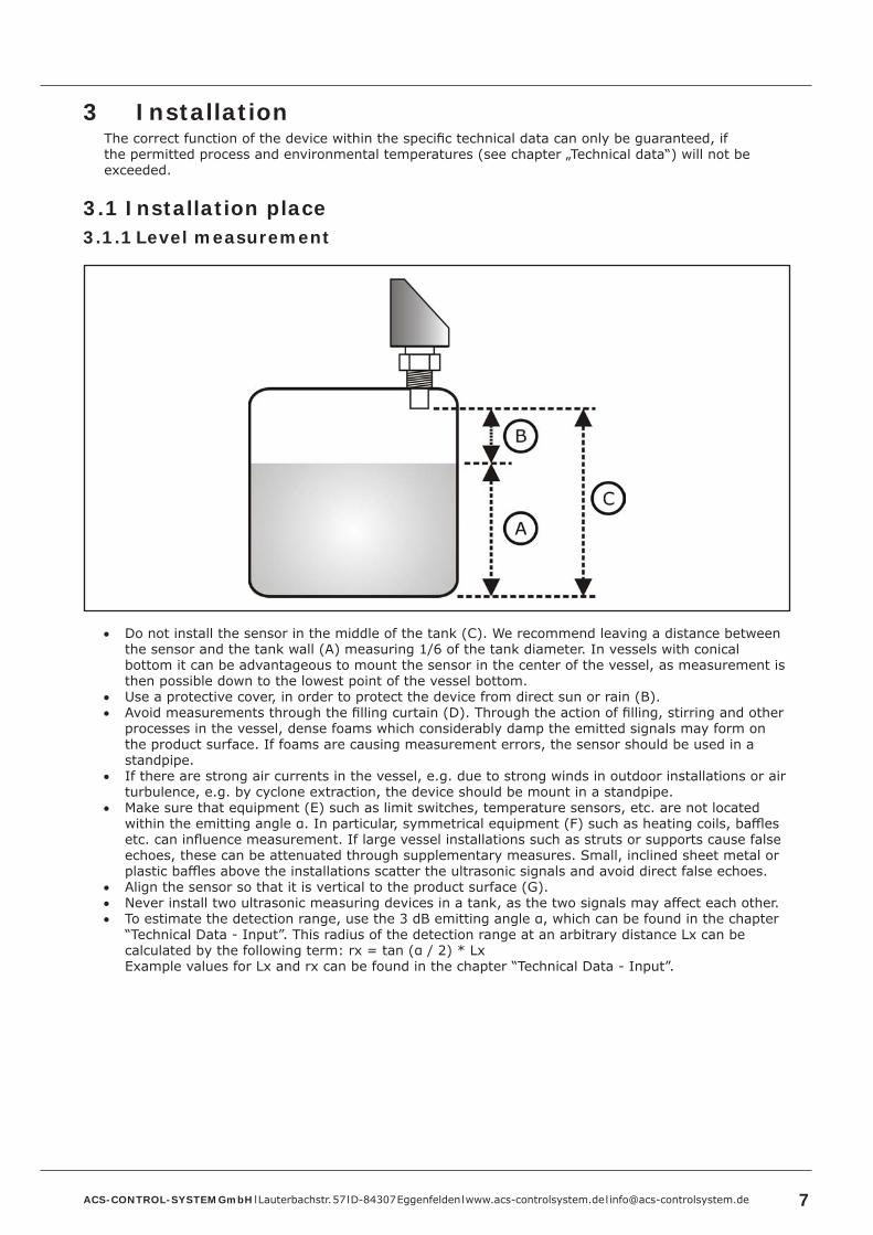
3 .1 Installation place3 .1 .1 Level measurement
• Do not install the sensor in the middle of the tank (C). We recommend leaving a distance between the sensor and the tank wall (A) measuring 1/6 of the tank diameter. In vessels with conical bottom it can be advantageous to mount the sensor in the center of the vessel, as measurement is then possible down to the lowest point of the vessel bottom.
• Use a protective cover, in order to protect the device from direct sun or rain (B).• Avoid measurements through the filling curtain (D). Through the action of filling, stirring and other
processes in the vessel, dense foams which considerably damp the emitted signals may form on the product surface. If foams are causing measurement errors, the sensor should be used in a standpipe.
• If there are strong air currents in the vessel, e.g. due to strong winds in outdoor installations or air turbulence, e.g. by cyclone extraction, the device should be mount in a standpipe.
• Make sure that equipment (E) such as limit switches, temperature sensors, etc. are not located within the emitting angle α. In particular, symmetrical equipment (F) such as heating coils, baffles etc. can influence measurement. If large vessel installations such as struts or supports cause false echoes, these can be attenuated through supplementary measures. Small, inclined sheet metal or plastic baffles above the installations scatter the ultrasonic signals and avoid direct false echoes.
• Align the sensor so that it is vertical to the product surface (G).• Never install two ultrasonic measuring devices in a tank, as the two signals may affect each other.• To estimate the detection range, use the 3 dB emitting angle α, which can be found in the chapter
“Technical Data - Input”. This radius of the detection range at an arbitrary distance Lx can be calculated by the following term: rx = tan (α / 2) * LxExample values for Lx and rx can be found in the chapter “Technical Data - Input”.

ACS-CONTROL-SYSTEM GmbH l Lauterbachstr. 57 l D-84307 Eggenfelden l www.acs-controlsystem.de l [email protected]
3 .1 .2 Installation in narrow shafts
• In narrow shafts with strong interference echoes, we recommend using a stand pipe resp. an ultrasound guide pipe (e.g. PE or PVC wastewater pipe) with a minimum diameter of 100mm.
• Make sure that the pipe is not soiled by accumulated dirt. If necessary, clean the pipe at regular intervals.
• The pipe must be provided with a sufficient venting hole (A) (Ø 5…10mm) at the upper edge.
3 .1 .3 Flow measurementExample: Triangular weir
• Install the device at the inflow side, as close above the maximum water level Hmax as possible (take into account the blocking distance BD).
• Position the device in the middle of the channel or weir.• Align the sensor membrane parallel to the water surface.• Keep to the installation distance of the channel or weir.

ACS-CONTROL-SYSTEM GmbH l Lauterbachstr. 57 l D-84307 Eggenfelden l www.acs-controlsystem.de l [email protected] 9
3 .2 Installation notes• Drive the system pressure free prior installation resp. deinstallation of the sensor.• The screw-in of the thread process connection by using the terminal enclosure, the connection plug
resp. the connection cable is not permitted.• The tightening of the thread process connection may only be done at the hexagon by a suitable
spanner and with the maximum permitted torque strength (see chapter „Technical data“).• The housing can be rotated every time, also at operation, mechanically by 300°.• The display can be rotated every time electrically by 180°.
3 .2 .1 Pressure / vacuumGauge pressure in the vessel does not influence the measuring result. Low pressure or vacuum does, however, damp the ultrasonic pulses. This influences the measuring result, particularly if the level is very low (≤ -0,2bar resp. -20kPa).
3 .2 .2 Vapor pressureThe vapor pressure at 20°C (68°F) gives a hint on the accuracy of the ultrasonic level measurement. If the vapor pressure at 20°C (68°F) is below 50mbar, ultrasonic level measurement is possible with a very high accuracy.
This is valid for water, aqueous solutions, water-solid-solutions, dilute acids (e.g. hydrochloric acid, sulfuric acid), dilute bases (e.g. caustic soda), oils, greases, slurries, pastes, etc.
High vapor pressures or outgassing media (e.g. ethanol, acetone, ammoniac) can influence the accuracy.
3 .2 .3 RangeThe sensor range is dependent on the measuring conditions.
The maximum range can be found in the chapter “Technical Data - Input”.
3 .2 .4 Blocking distanceIf the blocking distance is undershot, it may cause device malfunction.
• Install the device at a height so that the blocking distance BD (see chapter “Technical Data - Input”) is not undershot, even at maximum fill level Hmax.
• If the medium reaches the transducer, buildup can form on it and cause faulty measurements later on.

ACS-CONTROL-SYSTEM GmbH l Lauterbachstr. 57 l D-84307 Eggenfelden l www.acs-controlsystem.de l [email protected]
3 .2 .5 Nozzle installationUse a pipe nozzle if you cannot maintain the blocking distance in any other way.
• The interior of the nozzle must be smooth and may not contain any edges or welded joints. In particular, there should be no burr on the inside of the tank side nozzle end.
• To minimize disturbing factors, we recommend an angled socket edge (ideally 45°).• Note the specified limits for nozzle diameter and length.
Nozzle diameter D Maximum nozzle length LDN50 / 2“ 80mmDN80 / 3“ 240mmDN100 / 4“ 300mm≥ DN150 / 6“ 400mm
3 .2 .6 Standpipe measurementBy using a standpipe (surge or bypass tube), the influence of vessel installations, foam generation and turbulence is excluded.
• Standpipes must extend all the way down to the requested min. level, as measurement is only possible within the tube.
• The pipe must be provided with a sufficient venting hole (A) (Ø 5…10mm) at the upper edge.• Avoid large gaps and thick welding joints when connecting the tubes.• Measurement in a standpipe is not recommended for very adhesive products.

ACS-CONTROL-SYSTEM GmbH l Lauterbachstr. 57 l D-84307 Eggenfelden l www.acs-controlsystem.de l [email protected] 11
4 Electrical connectionThe electrical connection of the device must be carried out according to the respective country specific standards.Incorrect installation or adjustment could cause applicationally conditioned risks.
Warning!The instrument may only be installed if the supply voltage is switched off.
4 .1 Potential equalization - earthingThe device must be grounded.The earthing can be carried out by the metallic process connection.The metallic parts of the device are electrically connected with the socket of the plug M12.
4 .2 Connection cableUse only shielded signal and measurement wires and install these wires separated from power leading wires. Connect the cable shield of a connected cable only at one side to earth, ideally at the installation place of the device.
4 .3 Supply voltageThe voltage applied to the terminal contacts may not exceed the maximum permitted supply voltage to avoid damage of the electronic.The maximum permitted supply voltage range is:
Signal 0/4…20mA 9…30VDC
Signal 0…10V 14…30VDC
All connections are reverse polarity protected.
4 .4 Switch outputWarning!Inductive loads at the PNP switch outputs, e.g. relays, contactors or magnetic vents may only be used with a free-wheeling diode or a RC protection circuit to avoid high voltage peaks.
Note!For inauguration it is suggested, to deactivate all connected control devices, to avoid unwanted control reactions.
The load at the PNP switch output will be connected to the terminal +L of the supply voltage by a semiconductor switch contactless and by this bounce-free.At an activated switch state a positive signal near supply voltage is feed to the output.At deactivated switch state and at failure of supply voltage the semiconductor switch is shut off.The PNP switch output is current limited, overload and short circuit protected.

ACS-CONTROL-SYSTEM GmbH l Lauterbachstr. 57 l D-84307 Eggenfelden l www.acs-controlsystem.de l [email protected]
4 .5 Analogue output4 .5 .1 Current output – Load resistor
A load resistor, e.g. the measuring shunt of an evaluation device, requires a minimum supply voltage. Dependent on the connected supply voltage and the maximum output current, it results in a maximum value for this resistor, where a correct function is still possible.
4 .6 Connection schemeConductor color standard connection cable M12 – A-coded:
• BN = brown• WH = white• BU = blue• BK = black• GY = grey• YE = yellow• GN = green• PK = pink
4 .6 .1 Electronic output type M1x signal 0/4…20mA-0…10V, supply 24VDC
4 .6 .2 Electronic output type K1x signal 0/4…20mA-0…10V, 2x switch PNP, supply 24VDC

ACS-CONTROL-SYSTEM GmbH l Lauterbachstr. 57 l D-84307 Eggenfelden l www.acs-controlsystem.de l [email protected] 13
4 .6 .3 Electronic output type R1x signal 0/4…20mA-0…10V, 4x switch PNP, supply 24VDC

ACS-CONTROL-SYSTEM GmbH l Lauterbachstr. 57 l D-84307 Eggenfelden l www.acs-controlsystem.de l [email protected]
5 Operation5 .1 Operation and display parts
A – LCD display• Display of measuring value, device state and operation menu
B - Key Down• In the selection menu navigation downwards• In the set menu decreasing of value• Used, in combination with the key up, for leaving selection and set menu without applying
changings• Used, in combination with the key up, for a step backwards one menu item
C - Key Enter/Shift right• Access to operation menu• In the selection menu entering the selected sub menu• In the set menu applying the new value and digit shift right
D - Key Up• In the selection menu navigation upwards• In the set menu increasing of value• Used, in combination with the key down, for leaving selection and set menu without applying
changings• Used, in combination with the key down, for a step backwards one menu item
5 .2 Function scheme
A – CommissioningB – Operating mode (4..20mA/0..20mA/0..10V)C – Pulse rateD – Echo lossE – DampingF – Min/Max adjustment > e.g. 1,8..0,4m = 0..100%U – Limit min/max

ACS-CONTROL-SYSTEM GmbH l Lauterbachstr. 57 l D-84307 Eggenfelden l www.acs-controlsystem.de l [email protected] 15
I1 - Linearization > Level - display scaling e.g. 0,4..1,8 m = 0..2000 m3
I2 - Linearization > Percent 0..100 % - Lin. Percent 0..100 %I3 - No linearization
J - Signal output > e.g. 0..100 % = 4..20 mA resp. 0..20 mA resp. 0..10VR – Signal output > Percent 0..100 % - Lin. Percent 0..100 %K - Error signal evaluation
L1 - Switch / reset switch point S1L2 - Switch / reset switch point S2L3 - Switch / reset switch point S3L4 - Switch / reset switch point S4M1 - Error indication function S1M2 - Error indication function S2M3 - Error indication function S3M4 - Error indication function S4T – Impulse output S1 for quantity counter
N1 - Display scaling > Distance e.g. 0..100 % = 1,8..0,4 mN2 - Display scaling > Fill level e.g. 0..100 % = 0,4..1,8 mN3 - Display scaling > Percent 0..100 % = 0..100 %N4 - Display scaling > scaled e.g. 0..100 % = 0..2000N5 - Display scaling > Signal Output 0..100 % = 4..20 mA resp. 0..20 mA resp. 0..10 VO - Display unit > at display scaling scaled e.g. m3
P - Error indication displayS – Quantity counter > e.g. m3/h, l/minQ1 - Display - Distance e.g. 1,8..0,4 mQ2 - Display - Fill level e.g. 0,4..1,8 mQ3 - Display - Percent 0..100 %Q4 - Display - scaled e.g. 0..2000 m3
Q5 - Display - Signal Output 4..20 mA resp. 0..20 mA resp. 0..10 V
ACS-CONTROL-SYSTEM GmbH l Lauterbachstr. 57 l D-84307 Eggenfelden l www.acs-controlsystem.de l [email protected]
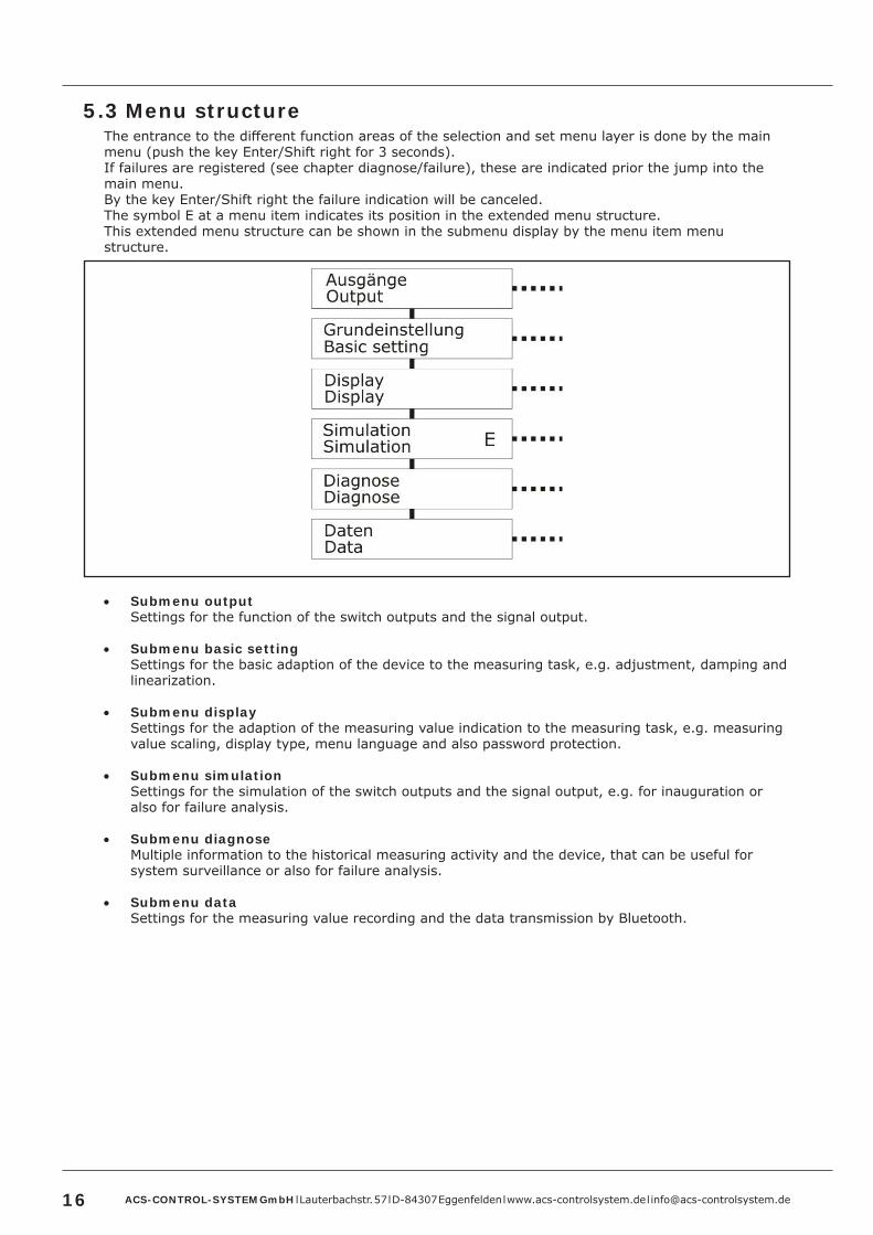
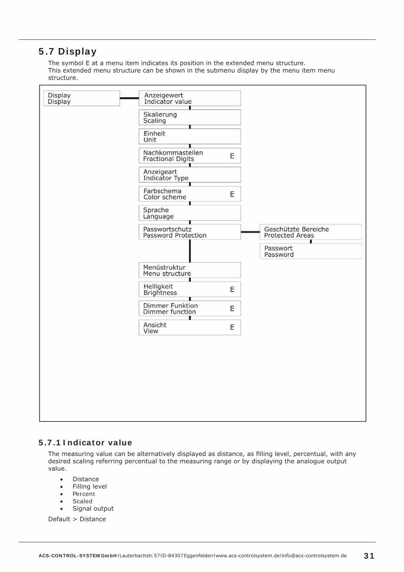
5 .3 Menu structureThe entrance to the different function areas of the selection and set menu layer is done by the main menu (push the key Enter/Shift right for 3 seconds).If failures are registered (see chapter diagnose/failure), these are indicated prior the jump into the main menu.By the key Enter/Shift right the failure indication will be canceled.The symbol E at a menu item indicates its position in the extended menu structure.This extended menu structure can be shown in the submenu display by the menu item menu structure.
• Submenu outputSettings for the function of the switch outputs and the signal output.
• Submenu basic setting Settings for the basic adaption of the device to the measuring task, e.g. adjustment, damping and linearization.
• Submenu displaySettings for the adaption of the measuring value indication to the measuring task, e.g. measuring value scaling, display type, menu language and also password protection.
• Submenu simulationSettings for the simulation of the switch outputs and the signal output, e.g. for inauguration or also for failure analysis.
• Submenu diagnoseMultiple information to the historical measuring activity and the device, that can be useful for system surveillance or also for failure analysis.
• Submenu dataSettings for the measuring value recording and the data transmission by Bluetooth.
ACS-CONTROL-SYSTEM GmbH l Lauterbachstr. 57 l D-84307 Eggenfelden l www.acs-controlsystem.de l [email protected] 17
5 .4 NavigationThe navigation in a submenu and in a selection window is done by the keys Up and Down.The selection of a submenu and the selection of a setting in a selection menu is done by the key Enter/Shift right.The jump backward from a submenu to the higher-level menu is done by the menu item back or by the simultaneous pushing the keys Up and Down.The leaving of a selection menu without applying the changings is done by the simultaneous pushing the keys Up and Down.
The input of a value or text in a set menu is done digit by digit.For the changing of the selected digit the keys Up and Down are used.For the changing of the digit the key Enter/Shift right is used.The applying of a set value resp. text is done by pushing the key Enter/Shift right for 3 seconds.The leaving of an set menu without applying a value resp. text is done by the simultaneous pushing the keys Up and Down.
After 5 minutes of inactivity the active submenu resp. selection menu will automatically be left and a change to the measuring value indication is executed.A jump backward is not executed from an active set menu.

ACS-CONTROL-SYSTEM GmbH l Lauterbachstr. 57 l D-84307 Eggenfelden l www.acs-controlsystem.de l [email protected]
5 .5 OutputThe symbol E at a menu item indicates its position in the extended menu structure.This extended menu structure can be shown in the submenu display by the menu item menu structure.
A – Hysteresis functionB – Window functionC – Error indication functionD – Impulse functionF – Pump function
5 .5 .1 Switch output S1 / S2 / S3 / S45 .5 .1 .1 Enabled
Each switch output can be activated resp. deactivated separately.
YesNo
Default > Yes

ACS-CONTROL-SYSTEM GmbH l Lauterbachstr. 57 l D-84307 Eggenfelden l www.acs-controlsystem.de l [email protected] 19
5 .5 .1 .2 Switch Point / Reset Switch PointThe input values refers to the set display value or acc. to display scaling.The reset switch point must be lower or equal to the switch point.At inverse measuring principle, e.g. distance measurement, the reset switch point must be greater or equal to the switch point.
The input range is limited to the measuring range.Default > S1 = 20% / S2 = 40% / S3 = 60% / S4 = 80%
5 .5 .1 .3 Switch Delay Time / Reset Switch Delay Time – EThe activation resp. deactivation of the switch output can be biased with a delay time (resolution 0,01s), to realize simple sequence control system.
The input range is indefinite.Default > 0s
5 .5 .1 .4 Function - E5 .5 .1 .4 .1 Hysteresis function S1/S2/S3/S4
The hysteresis function realizes a stable switch state, independent from system conditioned signal fluctuations around the adjusted set point.It can be used for realizing a signal controlled two-position control.The switch range is determined by definition of switch point and reset switch point.
In the menu Operating Mode, the working principle of the switch output can be inverted.
• Operating Mode Maximum
The switch output is activated, if the current measuring value overshoots the switch point and if the set switch point delay time has been expired.The switch output is deactivated, if the current measuring value undershoots the reset switch point and if the set reset switch point delay time has been expired.
• Operating Mode Minimum
The switch output is activated, if the current measuring value undershoots the reset switch point and if the set reset switch point delay time has been expired.The switch output is deactivated, if the current measuring value overshoots the switch point and if the set switch point delay time has been expired.
5 .5 .1 .4 .2 Window function S1/S2/S3/S4
The window function realizes a signal range – acceptance region –, where the switch output is set to a definitive switch state.The switch range is determined by definition of switch point, reset switch point and hysteresis.
In the menu Operating Mode, the working principle of the switch output can be inverted.
ACS-CONTROL-SYSTEM GmbH l Lauterbachstr. 57 l D-84307 Eggenfelden l www.acs-controlsystem.de l [email protected]
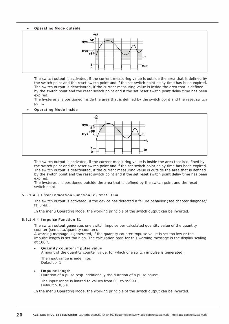
• Operating Mode outside
The switch output is activated, if the current measuring value is outside the area that is defined by the switch point and the reset switch point and if the set switch point delay time has been expired.The switch output is deactivated, if the current measuring value is inside the area that is defined by the switch point and the reset switch point and if the set reset switch point delay time has been expired.The hysteresis is positioned inside the area that is defined by the switch point and the reset switch point.
• Operating Mode inside
The switch output is activated, if the current measuring value is inside the area that is defined by the switch point and the reset switch point and if the set switch point delay time has been expired.The switch output is deactivated, if the current measuring value is outside the area that is defined by the switch point and the reset switch point and if the set reset switch point delay time has been expired.The hysteresis is positioned outside the area that is defined by the switch point and the reset switch point.
5 .5 .1 .4 .3 Error Indication Function S1/S2/S3/S4
The switch output is activated, if the device has detected a failure behavior (see chapter diagnose/failures).
In the menu Operating Mode, the working principle of the switch output can be inverted.
5 .5 .1 .4 .4 Impulse Function S1
The switch output generates one switch impulse per calculated quantity value of the quantity counter (see data/quantity counter).A warning message is generated, if the quantity counter impulse value is set too low or the impulse length is set too high. The calculation base for this warning message is the display scaling at 100%.
• Quantity counter impulse valueAmount of the quantity counter value, for which one switch impulse is generated.
The input range is indefinite.Default > 1
• Impulse lengthDuration of a pulse resp. additionally the duration of a pulse pause.
The input range is limited to values from 0,1 to 99999.Default > 0,5 s
In the menu Operating Mode, the working principle of the switch output can be inverted.
ACS-CONTROL-SYSTEM GmbH l Lauterbachstr. 57 l D-84307 Eggenfelden l www.acs-controlsystem.de l [email protected] 21
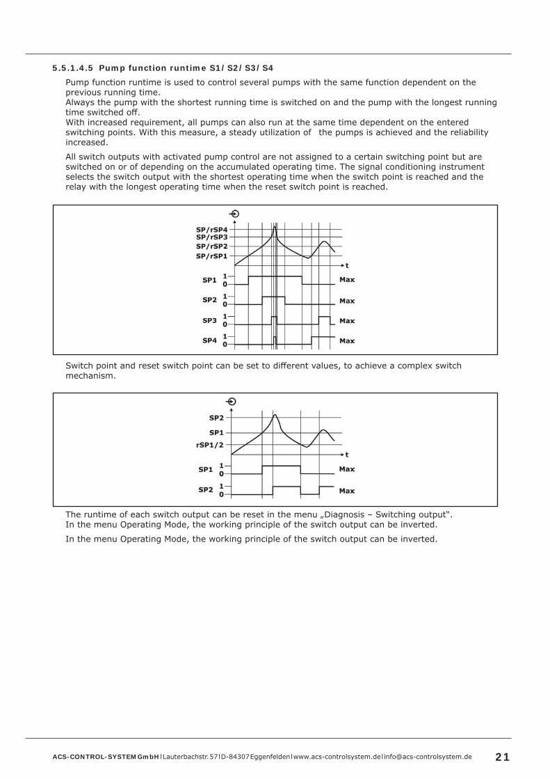
5 .5 .1 .4 .5 Pump function runtime S1/S2/S3/S4
Pump function runtime is used to control several pumps with the same function dependent on the previous running time. Always the pump with the shortest running time is switched on and the pump with the longest running time switched off.With increased requirement, all pumps can also run at the same time dependent on the entered switching points. With this measure, a steady utilization of the pumps is achieved and the reliability increased.
All switch outputs with activated pump control are not assigned to a certain switching point but are switched on or of depending on the accumulated operating time. The signal conditioning instrument selects the switch output with the shortest operating time when the switch point is reached and the relay with the longest operating time when the reset switch point is reached.
Switch point and reset switch point can be set to different values, to achieve a complex switch mechanism.
The runtime of each switch output can be reset in the menu „Diagnosis – Switching output“.In the menu Operating Mode, the working principle of the switch output can be inverted.
In the menu Operating Mode, the working principle of the switch output can be inverted.
ACS-CONTROL-SYSTEM GmbH l Lauterbachstr. 57 l D-84307 Eggenfelden l www.acs-controlsystem.de l [email protected]
5 .5 .1 .4 .6 Pump function sequential S1/S2/S3/S4
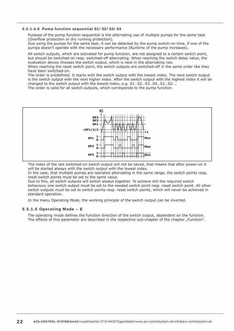
Purpose of the pump function sequential is the alternating use of multiple pumps for the same task (Overflow protection or dry running protection).Due using the pumps for the same task, it can be detected by the pump switch-on time, if one of the pumps doesn’t operate with the necessary performance (Runtime of the pump increases).
All switch outputs, which are activated for pump function, are not assigned to a certain switch point, but should be switched-on resp. switched-off alternating. When reaching the switch delay value, the evaluation device chooses the switch output, which is next in the alternating row.When reaching the reset switch point, the switch outputs are switched-off in the same order like they have been switched-on.The order is predefined. It starts with the switch output with the lowest index. The next switch output is the switch output with the next higher index. After the switch output with the highest index it will be changed to the switch output with the lowest index, e.g. S1…S2…S3…S4…S1…S2….The order is valid for all switch outputs, which corresponds to the pump function.
The index of the last switched-on switch output will not be saved, that means that after power-on it will be started always with the switch output with the lowest index.In the case, that multiple pumps are operated alternating in the same range, the switch points resp. reset switch points must be set to the same value.Due to this, all switch outputs will switch always together. To achieve still the required switch behaviour, one switch output must be set to the needed switch point resp. reset switch point. All other switch outputs must be set to switch points resp. reset switch points, which will never be achieved in standard operation.
In the menu Operating Mode, the working principle of the switch output can be inverted.
5 .5 .1 .5 Operating Mode – EThe operating mode defines the function direction of the switch output, dependent on the function.The effects of this parameter are described in the respective sub-chapter of the chapter „Function“.

ACS-CONTROL-SYSTEM GmbH l Lauterbachstr. 57 l D-84307 Eggenfelden l www.acs-controlsystem.de l [email protected] 23
5 .5 .1 .6 Forced switchover – EThis menu item is only available at function principle pump function runtime resp. pump function sequential.The purpose of the forced switchover is the change of a pump after a predefined dime.This gets relevant, if the measuring value does not change for a longer time and thus always the same pump is switched-on.The parameter forced switchover time defines the time, after that a forced switchover of the pump is processed.The menu „Forced switchover time“ is only available at activated forced switchover.The pump, which is switched-on, depends on the chosen pump function. If already all pumps of the pump function are switched-on, the pump stays switched-on.If the pump is already switched-on, when the forced switchover is activated, the timer will not be started. The timer starts after the next switch-off and a new switch-on.At the forced pump switchover, a set reset switch delay time will not be considered, that means the forced switchover is processed exactly after the set forced switchover time.At the forced pump switchover, a set switch delay time will be considered, that means the forced switchover to another pump is processed exactly after the time. The set switch delay time for this pump must be expired, before the new selected pump will be switched-on.
• Yes• No
Default > No
5 .5 .1 .7 Forced switchover timeThis menu is only available at activated forced switchover.The effects of this parameter are described in the chapter “Forced switchover”.The input range is indefinite.
Default > 1h
5 .5 .1 .8 Switch output TAGDue to the Switch output TAG each switch output can be separately marked with a label. At the indicator type digital the Sensor TAG is indicated in the display.
Up to 10 characters can be input.The input range is indefinite.Default > no Switch output TAG allocated
5 .5 .2 Signal outputThe nominal values of the analogue signal (4/20 mA resp. 0/10mA resp. 0/10 V) refers to the set display nominal values 0% and 100%
5 .5 .2 .1 Operating ModeDefines the type of the analogue output signal
• 4-20 mA• 0-20 mA• 0-10V
Default > 4-20 mA
5 .5 .2 .2 Error SignalDefines, dependent on the operating mode, the analogue output signal regarding operating range and if errors (see chapter diagnose/failures) are registered.
Operating mode 4-20mAThe linear output range is 3,8…20,5mA.
• Off >> At exceedance the limit values will be kept.• 3.6mA >> At exceedance the error signal 3,6mA is generated.• 22mA >> At exceedance the error signal 22mA is generated.

ACS-CONTROL-SYSTEM GmbH l Lauterbachstr. 57 l D-84307 Eggenfelden l www.acs-controlsystem.de l [email protected]
Operating mode 0-20mAThe linear output range is 0…20,5mA.
• Off >> At exceedance the limit values will be kept.• 0mA >> At exceedance the error signal 0mA is generated.• 22mA >> At exceedance the error signal 22mA is generated.
Operating mode 0-10VThe linear output range is 0…10,5V.
• Off >> At exceedance the limit values will be kept.• 0V >> At exceedance the error signal 0V is generated.• 11V >> At exceedance the error signal 11V is generated.
Default > Off
5 .5 .2 .3 Invert SignalInverts, dependent on the operating mode, the analogue output signal.
• 4-20 mA >> 20-4 mA• 0-20 mA >> 20-0 mA• 0-10 V >> 10-0 V
Default > No
5 .5 .2 .4 SourceDefines the source for the generation of the signal output. For the source, it can be chosen between the measuring value before (%) or after (Lin %) an optionally set linearization.This allows e.g. the output of a linear filling level at the signal output, whereas a linearized volume is shown at the display.
• Lin %• %
Default > Lin %

ACS-CONTROL-SYSTEM GmbH l Lauterbachstr. 57 l D-84307 Eggenfelden l www.acs-controlsystem.de l [email protected] 25
5 .6 Basic settingThe symbol E at a menu item indicates its position in the extended menu structure.This extended menu structure can be shown in the submenu display by the menu item menu structure.
5 .6 .1 Measure conditions
Preselection for optimized adaption at increased requirements.
• Usage
o Object detectionEach measuring value at the set pulse rate will be displayed resp. output.
o FluidThe measured signal will be checked for plausibility and fast signal changes > 1m/min, e.g. due to an agitator, will be suppressed.If faster signal changes occurs, e.g. at filling or emptying, this can be allowed separately (menu “Fast change rate”)
o Bulk SolidThe measured signal will be checked for plausibility and fast signal changes > 1m/min, e.g. due to an agitator, will be suppressed.If faster signal changes occurs, e.g. at filling or emptying, this can be allowed separately (menu “Fast change rate”)
Default > Fluid
ACS-CONTROL-SYSTEM GmbH l Lauterbachstr. 57 l D-84307 Eggenfelden l www.acs-controlsystem.de l [email protected]
• Extreme foam / Extreme dustAt extreme foam resp. extreme dust the measuring signal will be damped very much.The activation of this function allows at such applications a significant improvement of the signal evaluation.
Default > no
• Fast change rateThe measured signal can be checked for plausibility and only very fast jumpy signal signal changes will be suppressed.
Default > no
5 .6 .2 CommissioningThe commissioning function can be used to adapt the device to the constructive conditions.Therefore the device must be operated in it’s finally installed position at the maximum possible distance resp. at the lowest possible known filling level.After setting the vessel type the detected measuring value must be confirmed or possibly corrected.Afterwards the detection of the envelope curve for the error echo suppression is processed.Error echoes causing installations, positioned below the filling level when processing the commissioning function, cannot be detected.
5 .6 .3 Min/Max-AdjustmentThe min/max-adjustment set the measuring range limits.2 points are defined, that set the ratio of the measured distance signal and the operating range of the device.The current measuring value is indicated in the display.The input of the measuring range limits 0% and 100% are not mandatory. Values within the measuring range e.g. 11% and 87% can be also input. In this case there is an automatic calculation to 0% resp. 100%. The higher the difference between these points, the more precise is the following calculation.The min/max-adjustment is relevant for linearization, signal output and display scaling.
• Lower adjustment value• Upper adjustment value
The input range is indefinite.Default > Lower calibrated measuring value = 0% / Upper calibrated measuring value = 100%
5 .6 .4 Pulse rate – EThe pulse rate defines the measurement velocity resp. the repetition rate of the ultrasonic measurement pulses.The use of a slower pulse rate (tp) can be used for energy saving and also for conservation of the sensor (reduction of component stress due to high energetic ultrasonic signals).The use of a slower pulse rate extends the actualization time of display and outputs by the respective factor.
• very fast – maximum pulse rate (see chapter „Technical Data“) x factor 1• fast – maximum pulse rate (see chapter „Technical Data“) x factor 0,5• slow – maximum pulse rate (see chapter „Technical Data“) x factor 0,25
Default > very fast

ACS-CONTROL-SYSTEM GmbH l Lauterbachstr. 57 l D-84307 Eggenfelden l www.acs-controlsystem.de l [email protected] 27
5 .6 .5 Limit min/max – EIf the measuring value exceeds the limits of the Min/Max-Adjustment, these limits are kept at activated function. An exceedance is not possible.At deactive function measurement values besides the limit values are output.This function is especially useful at a flow measurement to avoid negative flow measuring values.
• deactive• active
Default > deactive
5 .6 .6 On echo lossIf no measuring signal can be detected, e.g. due to a too high distance or a strong deviation of the ultrasonic signal, up to the next valid measuring signal alternatively the last detected measuring value can be hold or the minimum resp. maximum adjusted limit value can be output.
• hold• maximum measuring range• minimum measuring range
Default > hold
5 .6 .7 Damping
The damping influences the reaction speed of display, output signal and switch output at a change of the measuring signal.The behavior of display and output signal follows an exponential characteristic with the damping time constant t.Within the time period t the output signal increases respectively by 63% of the existing deviation.With 99,3%, the end value is nearly achieved after 5 t.The set time equals 5 t.
The input range is indefinite.Default > 1 sec

ACS-CONTROL-SYSTEM GmbH l Lauterbachstr. 57 l D-84307 Eggenfelden l www.acs-controlsystem.de l [email protected]
5 .6 .8 LinearizationDue to the integrated linearization function it is possible, to linearize a measuring signal e.g. for volume calculation of conical or horizontal cylindrical vessels or also for flow calculation.
A - Tank with linearization points 1 / 2 / 3 / 4B - Characteristic distance - level not linearizedC - Characteristic distance - level linearized
5 .6 .8 .1 Predefined linearization curves• Linear - no linearization
Volume linearization• Horizontal cylindrical vessel• Spherical vessel
Flow linearization• Venturi, trapezodial weir, rectangle weir• Palmer-Bowlus-Flume• V-Notch, triangle weir
Free linearization characteristic with up to 40 points• Custom
Default > Linear

ACS-CONTROL-SYSTEM GmbH l Lauterbachstr. 57 l D-84307 Eggenfelden l www.acs-controlsystem.de l [email protected] 29
5 .6 .8 .2 Input mode custom defined linearization• Percent / Linearized Percent• Filling level / Display Scaling• CSV-file via Bluetooth-interface
The percentual input (referring to the measuring range) is only possible without applying measuring value, whereby the input in filling level and display scaling e.g. liter can be done without applying measuring signal as well as with applying measuring signal.
At the linearization without applying measuring signal, for each linearization point a needed signal value (in percent or filling level) is input and referred to the needed output value (in percent or primary unit) that must be also input.At the linearization with applying measuring signal, for each linearization point the current measuring value is captured and referred to the output value (acc. to display scaling) that must be input.
• Linearization PointsThe number of linearization points for the complete measuring characteristic must be defined.
The input range is limited to values from 2 to 40.Default > 2
• LinearizationAt the input mode percent / linearized percent the input signal refers percentual to the measuring range, that is defined at the min./max. adjustment for 0% and 100%. The output signal must also be considered percentual.At the input mode filling level / display scaling the input signal refers to the filling level (inverted distance). The output signal refers to the display range, that is defined in the display scaling.The complete characteristic, eventually also the measuring range end values 0% and 100% must be defined, cause the measuring range end values from the min./max. adjustment are not copied into the linearization table.
The input range is indefinite.Default > Linearization point 1 > 0.000% = 0.000% resp. 0.000bar / Linearization point 2 > 100.000% = 100.000% resp. 1.000bar
• StoreInput linearization points are not automatically stored loss-protected.To store one or also more linearization points loss-protected, the function store must be executed.
5 .6 .9 Sensor TAGDue to the Sensor TAG different devices can be differentiated. At the indicator type digital the Sensor TAG is indicated in the display.The Sensor TAG is added automatically to the Bluetooth-name, to allow the device identification when using multiple devices in reception range.
Up to 19 characters can be input.The input range is indefinite.Default > no Sensor TAG allocated

ACS-CONTROL-SYSTEM GmbH l Lauterbachstr. 57 l D-84307 Eggenfelden l www.acs-controlsystem.de l [email protected]
5 .6 .10 Date/TimeInput of date and time. For the measurement value recording, the measurement values are supplied with a time stamp of the integrated real time clock, which includes date and time. The set values are buffered at a short time (see chapter „Technical data“) supply voltage fail, whereas a longer failure resets the values. The values must then be set again.At the battery powered system the values are buffered also at a long term failure of the supply voltage.
The input range is limited to conclusive values for date and time. Default > 01.01.2001 / 00:00:00 resp. current date / current time
5 .6 .11 Factory ResetThe factory reset changes all settings to default values.The factory reset does not concern:
• Diagnose data• Historical measuring data• Storage interval• Custom defined linearization
ACS-CONTROL-SYSTEM GmbH l Lauterbachstr. 57 l D-84307 Eggenfelden l www.acs-controlsystem.de l [email protected] 31
5 .7 DisplayThe symbol E at a menu item indicates its position in the extended menu structure.This extended menu structure can be shown in the submenu display by the menu item menu structure.
5 .7 .1 Indicator valueThe measuring value can be alternatively displayed as distance, as filling level, percentual, with any desired scaling referring percentual to the measuring range or by displaying the analogue output value.
• Distance• Filling level• Percent• Scaled• Signal output
Default > Distance

ACS-CONTROL-SYSTEM GmbH l Lauterbachstr. 57 l D-84307 Eggenfelden l www.acs-controlsystem.de l [email protected]
5 .7 .2 ScalingThis menu item is only available at indicator value scaled.By defining a scaling the measuring range can be rescaled into any desired numerical range. This allows e.g. the indication of the volume in liter.The current measuring value is indicated in the display.The input of the measuring range limits 0% and 100% are not mandatory. Values within the measuring range e.g. 11% and 87% can be also input. In this case there is an automatic calculation to 0% resp. 100%.
• Lower display value• Upper display value
The input range is indefinite.Default > Measuring value 0.000% = Display 0.000 / Measuring value 100.000% = Display 1.000
5 .7 .3 UnitThis menu item is only available at indicator value scaledIf a scaled indicator value is used, additionally an unit can be selected, that is indicated in the display (not at indicator type vertical bargraph).The unit is only indicated as text and is not included into calculations.There are multiple predefined units in different categories available.
Mass• kg / t / lb
Volume• l / hl / m3 / in3 / gal / ft3
Height• mm / cm / m / in / ft
Pressure• mbar / bar / Pa / kPa / MPa / Psi / Torr / mmH2O
Flow• l/s / l/min / l/h / m3/s / m3/min / m3/h / lb/s / gal/s
Custom definedUp to 10 characters can be input.The input range is indefinite.Default > no text allocated
5 .7 .4 Fractional Digits – EThe measuring value can be formatted by the use of fractional digits.Is the indication of the measuring value with the current fractional digits number not possible, a change to the correct fractional digits number is executed automatically.
The input range is limited to values from 0 to 3.Default > 3
ACS-CONTROL-SYSTEM GmbH l Lauterbachstr. 57 l D-84307 Eggenfelden l www.acs-controlsystem.de l [email protected] 33
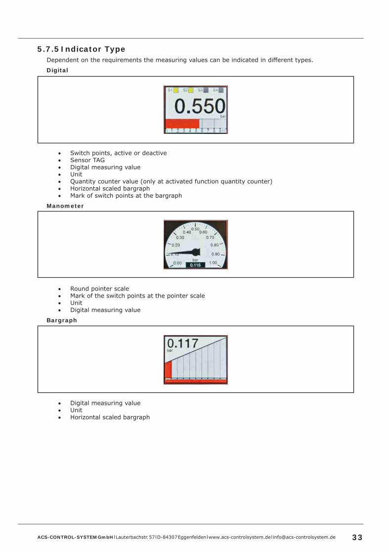
5 .7 .5 Indicator TypeDependent on the requirements the measuring values can be indicated in different types.
Digital
• Switch points, active or deactive• Sensor TAG• Digital measuring value• Unit• Quantity counter value (only at activated function quantity counter)• Horizontal scaled bargraph• Mark of switch points at the bargraph
Manometer
• Round pointer scale• Mark of the switch points at the pointer scale• Unit• Digital measuring value
Bargraph
• Digital measuring value• Unit• Horizontal scaled bargraph
ACS-CONTROL-SYSTEM GmbH l Lauterbachstr. 57 l D-84307 Eggenfelden l www.acs-controlsystem.de l [email protected]
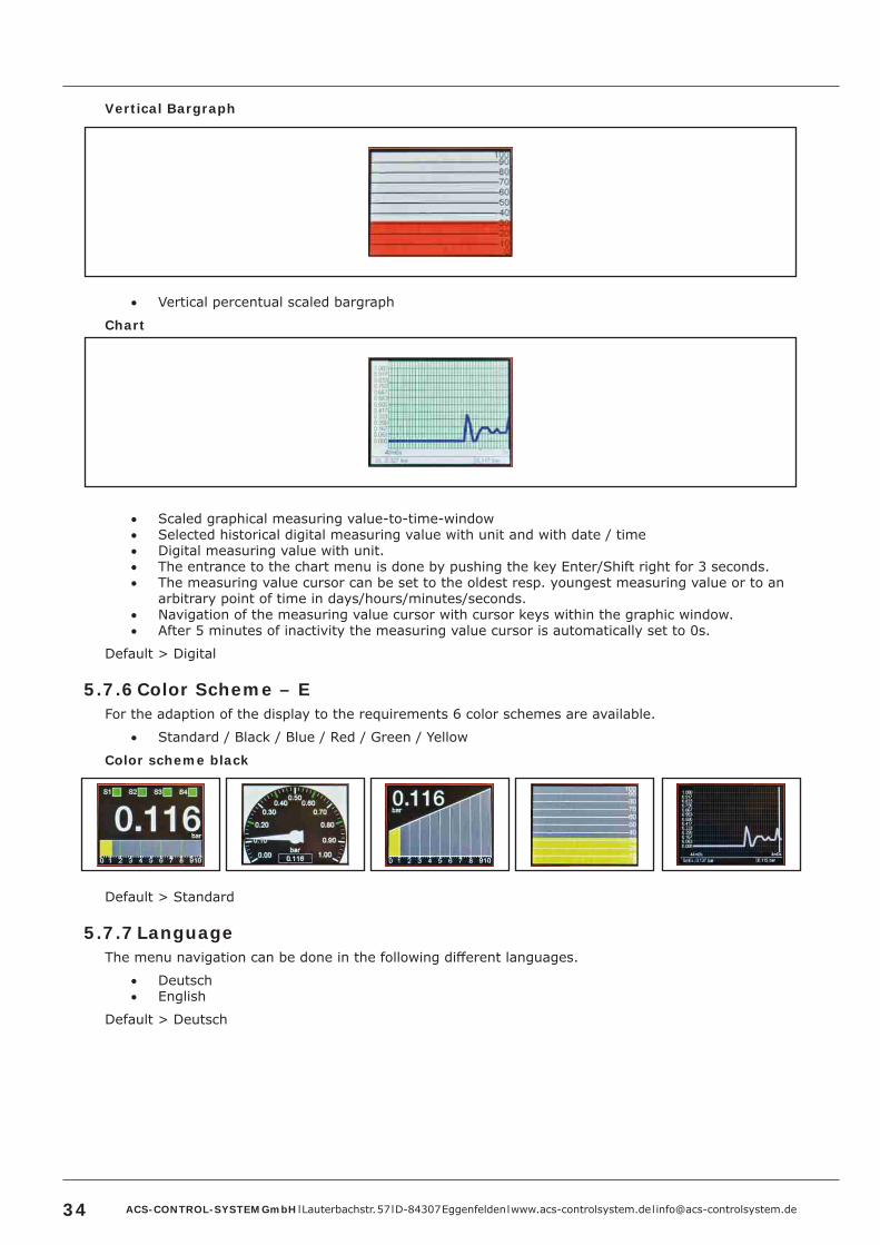
Vertical Bargraph
• Vertical percentual scaled bargraph
Chart
• Scaled graphical measuring value-to-time-window• Selected historical digital measuring value with unit and with date / time• Digital measuring value with unit.• The entrance to the chart menu is done by pushing the key Enter/Shift right for 3 seconds.• The measuring value cursor can be set to the oldest resp. youngest measuring value or to an
arbitrary point of time in days/hours/minutes/seconds.• Navigation of the measuring value cursor with cursor keys within the graphic window.• After 5 minutes of inactivity the measuring value cursor is automatically set to 0s.
Default > Digital
5 .7 .6 Color Scheme – EFor the adaption of the display to the requirements 6 color schemes are available.
• Standard / Black / Blue / Red / Green / Yellow
Color scheme black
Default > Standard
5 .7 .7 LanguageThe menu navigation can be done in the following different languages.
• Deutsch• English
Default > Deutsch

ACS-CONTROL-SYSTEM GmbH l Lauterbachstr. 57 l D-84307 Eggenfelden l www.acs-controlsystem.de l [email protected] 35
5 .7 .8 Password ProtectionFor the protection of the settings against unauthorized persons individual or all main menu items can be protected by a password.At each activation of the main menu the password protection is active.An unknown or forgotten password can be erased by use of a service code and an activation code. These codes can be requested at the manufacturer.
• Protected Areaso Outputo Basic Settingo Displayo Simulationo Diagnoseo Data
Default > all No
• PasswordUp to 10 characters can be input.The input range is indefinite.Default > no Password allocated
5 .7 .9 Menu StructureFor a breakdown illustration of the menu navigation different menu items (mark E in the menu structures overview) are arranged in a removable extended structure.To achieve access to all functions of the device, the extended menu structure must be activated.
• Normal• Extended
Default > Normal
5 .7 .10 Brightness – EFor the adaption of the display to the requirements the brightness of the backlight can be varied in a wide range.For the protection of the backlight at higher environmental temperatures, a reduction of the brightness can be necessary.At an input value of 0 a minimum residual brightness is already present.The input range is limited to values from 0 to 100.Default > 75

ACS-CONTROL-SYSTEM GmbH l Lauterbachstr. 57 l D-84307 Eggenfelden l www.acs-controlsystem.de l [email protected]
5 .7 .11 Dimmer function – ETo reduce the supply current and also to minimize the system typical aging influences on the brightness of the backlight an automatic dim after 5 minutes of inactivity (no key touch) can be activated.
• 0% / 10% / 20% / 30% / 40% / 50% / Off
Default > Off
5 .7 .12 View – EFor the adaption of the display to the requirements of the installation situation the view of the display can be rotated by 180°. In combination with the mechanical rotatability of app. 330° a readability from all directions in all installation positions is possible.
• Normal• 180°
Default > Normal

ACS-CONTROL-SYSTEM GmbH l Lauterbachstr. 57 l D-84307 Eggenfelden l www.acs-controlsystem.de l [email protected] 37
5 .8 Simulation – EThe symbol E at a menu item indicates its position in the extended menu structure.This extended menu structure can be shown in the submenu display by the menu item menu structure.
5 .8 .1 Output5 .8 .1 .1 Switch Output S1/S2/S3/S4
The switch output is activated resp. deactivated regardless of an already existing activation and also regardless of delay times.
5 .8 .1 .2 Signal OutputAt the signal output an analogue signal is output regardless of the current measuring value.The input range is limited, dependent on the set Operating Mode.
• 3.600 – 22.00 mA (4-20 mA)• – 22.00 mA (0-20 mA)• – 11.00 V (0-10 V)
5 .8 .2 Display ValueThe display value can be simulated, whereby all following functional steps (signal output, switch output) are also simulated acc. to the settings.
The input range is limited to the set measuring range.

ACS-CONTROL-SYSTEM GmbH l Lauterbachstr. 57 l D-84307 Eggenfelden l www.acs-controlsystem.de l [email protected]
5 .9 Diagnosis
5 .9 .1 Envelope curveThe current measuring signal is displayed as curve.The envelope curve is displayed, below those the measuring signal is ignored.The valid measuring signal is marked by a vertical mark.Downright the characteristic curve the current distance value is displayed with unit m and the corresponding measured signal level in dB.
Cursor resp . Zoom modeBelow and left of the characteristic curve the position of a shiftable cursor is indicated.A simple left-right-arrow-symbol allows a shift of the cursor by the keys Up resp. Down.By simultaneous pushing of the keys Up and Down it is switched to the zoom mode for the x-axis. This is indicated by a doubled left-right-arrow-symbol.The zoom is referring to the current cursor position.
The display of the envelope curve is canceled by pushing the key Enter/Shift right for 3 seconds.

ACS-CONTROL-SYSTEM GmbH l Lauterbachstr. 57 l D-84307 Eggenfelden l www.acs-controlsystem.de l [email protected] 39
5 .9 .2 Switching Outputs5 .9 .2 .1 Operation Cycles S1/S2/S3/S4
The number of operation cycles per switch output is indicated.An operation cycle is a complete change of the switch state till back to the start state, thus deactive - active - deactive.
5 .9 .2 .2 Runtime S1/S2/S3/S4The runtime per switch output is indicated.The runtime of each switch output can be reset here separately.At the pump function runtime, this is especially necessary after a pump exchange, to include the new pump into the runtime dependent activation.
5 .9 .3 FailureThe device registers multiple of short time or also continuous existing functional failures in type and frequency of occurrence.
• Echo lostNo measurable echo signal available
• Over Rangeexceeding the signal output range (dependent on Operating Mode)
o 20.5 mA (4-20 mA)o 20.5 mA (0-20 mA)o 10.5 V (0-10 V)
• Under Rangeexceeding the signal output range (dependent on Operating Mode)
o 3.8 mA (4-20 mA)o -0.4 mA (0-20 mA) – theoretical valueo -0.5 V (0-10 V) – theoretical value
• Sig . out breakwire break at signal output on signal output not connected at Operating Mode 4-20 mA resp. 0-20 mA
5 .9 .4 Error MessagesThe type of failure, that leads to the device reactions
• Indication on display• Error signal at analogue output, depending on selected operating mode• Error function at switching output, depending on settings
can be selected.
The following failures can be selected:
• Output overflowOvershoot of the analogue output range OutA1 depending on selected operating mode
o Operating mode 4-20mA >> 21mAo Operating mode 0-20mA >> 21mAo Operating mode 0-10V >> 10,5V
Default > activated
ACS-CONTROL-SYSTEM GmbH l Lauterbachstr. 57 l D-84307 Eggenfelden l www.acs-controlsystem.de l [email protected]
• Output underflowUndershoot of the analogue output range OutA1 depending on selected operating mode
o Operating mode 4-20mA >> 3,8mAo Operating mode 0-20mA >> -0,4mA – theoretical valueo Operating mode 0-10V >> -0,5V – theoretical value
Default > activated
• Temperature sensorError of the temperature sensor, which is integrated within the ultrasonic sensor, e.g. short circuit resp. wire break
Default > activated
• Echo lossNo measuring signal can be detected, e.g. due to a too high distance or a strong deviation of the ultrasonic signal
Default > activated
• Power loss
Default > deactivated
5 .9 .5 Min ./Max . Drag IndicatorThe drag indicator is used for detection and indication of the minimum and maximum registeredmeasuring values.The drag indicator can be separately reset by pushing the key Shift right/Enter.
5 .9 .6 Operating HoursThe operating hours of the device since the last device start-up are detected.The indication is done in hours.
5 .9 .7 Operating Hours totalThe operating hours of the device since the first device start-up are detected.The indication is done in hours.
5 .9 .8 System StartsThe number of the occurred system starts resp. device restarts is registered.
5 .9 .9 Min ./Max . Device TemperatureThe minimum and maximum temperature of the electronic in the area of the terminal enclosure (not the process temperature) is registered.
5 .9 .10 Process TemperatureThe current process temperature in the area of the transducer is registered.
5 .9 .11 Min ./Max . Process TemperatureThe minimum and maximum process temperature in the area of the transducer is registered.
5 .9 .12 Calibration DateIndication of the date (format DDMMJJ), the calibration by factory is done.
5 .9 .13 Serial NumberIndication of the serial number of the device.
5 .9 .14 InfoIndication of manufacturer data and firmware version

ACS-CONTROL-SYSTEM GmbH l Lauterbachstr. 57 l D-84307 Eggenfelden l www.acs-controlsystem.de l [email protected] 41
5 .10 Data
The device is able to record app. a half million measuring values loss-protected.The recording is made in ring memory method, whereas after an overflow the oldest measuring values are overwritten next.The stored measuring values can be displayed graphically in the indicator type chart or exported as CSV-file per Bluetooth-interface.By the Bluetooth-interface the download of linearization or firmware files is possible.
5 .10 .1 BluetoothFor the Bluetooth-communication two authentication methods are available.
• Unprotected transmissionNo PIN is usedCause the device does only receive/send files only after selection in the menu, this is the most simple and recommended way of transmission.If no PIN is used, each communication is uncoded, but the devices must not connect together.
ACS-CONTROL-SYSTEM GmbH l Lauterbachstr. 57 l D-84307 Eggenfelden l www.acs-controlsystem.de l [email protected]
• Protected resp . encoded transmissionA PIN is used.If a PIN is used, the devices must be connected together for a transmission. The procedure differs depending on the end device.A PIN must be input and the visibility must be switched to on.Afterwards the connection can be made at the end device.In the end device the same PIN must be used, that is input in the device.After the file transmission the visibility should be switched to off.Note: For a definite identification of the devices it is recommended to use a Sensor TAG.
5 .10 .1 .1 Send measure dataThe recorded measuring values can be transmitted as a CSV-file to a Bluetooth end device.Alternatively all measuring values or only the measuring values from the measuring value cursor (setting in the chart menu) till to the current measuring value can be transmitted.After the selection end devices with Bluetooth-ability are searched and after selection and approval the measuring values are transmitted.
5 .10 .1 .2 Receive CSV Lin . TableTo simplify enormous linearization procedures directly at the device, it is possible to generate alinearization table as CSV-file and transmit it into the device.There are different tank calculation programs available to calculate the linearization of a tank form comfortably.The CSV-file must match a defined formatting.
• Comments can be marked with a leading *.• Separator Tab• Decimal separator dot or comma.• First value percentual filling level, second value linearized percent.• Table length maximum 40
Example file*************************************** Container type: spherical tank* d=1000,000* 0% = 0,000* 100% = 100,000**************************************0,00 0,003,13 0,296,25 1,129,38 2,4712,50 4,3015,63 6,5618,75 9,2321,88 12,2625,00 15,6328,13 19,2831,25 23,1934,38 27,3337,50 31,6440,63 36,1043,75 40,6746,88 45,3250,00 50,0053,13 54,6856,25 59,3359,38 63,9062,50 68,3665,63 72,6768,75 76,8171,88 80,7275,00 84,3878,13 87,7481,25 90,7784,38 93,4487,50 95,7090,63 97,5393,75 98,8896,88 99,71100,00 100,00

ACS-CONTROL-SYSTEM GmbH l Lauterbachstr. 57 l D-84307 Eggenfelden l www.acs-controlsystem.de l [email protected] 43
5 .10 .1 .3 Receive firmware updateThe internal software of the device (firmware) can be updated by a new firmware, which could include functional improvements, functional extensions, new functions or also customer specific modifications.At the file transmission the safety of the power supply must be ensured. A power fail can lead to a completely irreversible device failure.
5 .10 .1 .4 PINFor a protected resp. encoded data transmission a PIN must be input.
The input range is limited to values from 000000 to 999999.Default > no PIN allocated
5 .10 .1 .5 VisibilityTo transmit a file to the device, it must be visible in the Bluetooth network. Other end devices can identify only visible devices.
Default > Off
5 .10 .2 Record valueThe measuring value can be alternatively recorded as distance, as filling level, percentual, with any desired scaling referring percentual to the measuring range or by displaying the analogue output value.
• Distance• Filling level• Percent• Scaled• Signal output
Default > Distance
5 .10 .3 Storage intervalThe storage interval defines the time interval between two measuring values, which should be stored in the measuring value memory.
The input range is limited to values from 1 to 99999.Default > 60 s
5 .10 .4 Activation RecordingTo start the recording of measuring values, this must be activated.
• AlwaysEach measuring value will be stored at the set storage interval.
• DeactiveThe measuring value recording is switched off.
• Threshold valueThe measuring value recording at the set storage interval will be switched on at overrun of the set threshold value (menu „Active over“) resp. switched off at underrun of the set threshold value (menu „Deactive under“)
The input range is limited to values from 1 to 99999.Default > 0.000
Default > Deactive
5 .10 .5 Delete measure dataAll existing stored measuring values in the measuring value memory are erased.
5 .10 .6 Quantity counterThe quantity counter integrates the calculated measuring values from the display scaling by the time. These values are stored every second.If the eventually activated impulse output cant output all impulses time conformal due to a too high frequency, all impulses are output afterwards until all accumulated impulses could be output, also if the flow is already lower or has stopped. Thus the amount of output pulses fits always to the quantity counter. Nevertheless this should be avoided from the first by a correct setting.
ACS-CONTROL-SYSTEM GmbH l Lauterbachstr. 57 l D-84307 Eggenfelden l www.acs-controlsystem.de l [email protected]
Quantity counter active
• Yes• No
Default > No
Quantity counter
The current quantity counter value, which is calculated at the moment of entering the menu, is displayed. This value can be actualized by the keys Up or Down.
Unit
• Volumel / hl / m3 / in3 / gal / ft3
• User definedUp to 10 characters can be input.The input range is indefinite.Default > no text allocated
Time base
• Hours• Minutes• Seconds
Default > Hours
Set
The value of the quantity counter can be preset to an arbitrary value.
The input range corresponds with the settings of the display scaling.Default > 0
Reset
The quantity counter value is reset to 0.
ACS-CONTROL-SYSTEM GmbH l Lauterbachstr. 57 l D-84307 Eggenfelden l www.acs-controlsystem.de l [email protected] 45
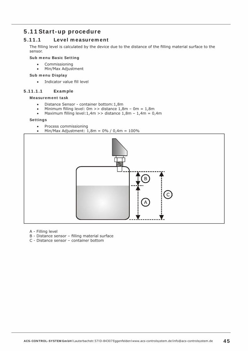
5 .11 Start-up procedure5 .11 .1 Level measurement
The filling level is calculated by the device due to the distance of the filling material surface to the sensor.
Sub menu Basic Setting
• Commissioning• Min/Max Adjustment
Sub menu Display
• Indicator value fill level
5 .11 .1 .1 ExampleMeasurement task
• Distance Sensor - container bottom:1,8m• Minimum filling level: 0m >> distance 1,8m – 0m = 1,8m• Maximum filling level:1,4m >> distance 1,8m – 1,4m = 0,4m
Settings
• Process commissioning• Min/Max Adjustment: 1,8m = 0% / 0,4m = 100%
A - Filling levelB - Distance sensor – filling material surfaceC - Distance sensor – container bottom
ACS-CONTROL-SYSTEM GmbH l Lauterbachstr. 57 l D-84307 Eggenfelden l www.acs-controlsystem.de l [email protected]
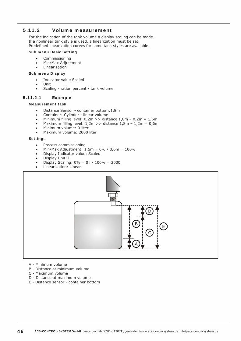
5 .11 .2 Volume measurementFor the indication of the tank volume a display scaling can be made.If a nonlinear tank style is used, a linearization must be set.Predefined linearization curves for some tank styles are available.
Sub menu Basic Setting
• Commissioning• Min/Max Adjustment• Linearization
Sub menu Display
• Indicator value Scaled• Unit• Scaling - ration percent / tank volume
5 .11 .2 .1 ExampleMeasurement task
• Distance Sensor - container bottom:1,8m• Container: Cylinder - linear volume• Minimum filling level: 0,2m >> distance 1,8m – 0,2m = 1,6m• Maximum filling level: 1,2m >> distance 1,8m – 1,2m = 0,6m• Minimum volume: 0 liter• Maximum volume: 2000 liter
Settings
• Process commissioning• Min/Max Adjustment: 1,6m = 0% / 0,6m = 100%• Display Indicator value: Scaled• Display Unit: l• Display Scaling: 0% = 0 l / 100% = 2000l• Linearization: Linear
A - Minimum volumeB - Distance at minimum volumeC - Maximum volumeD - Distance at maximum volumeE - Distance sensor - container bottom
ACS-CONTROL-SYSTEM GmbH l Lauterbachstr. 57 l D-84307 Eggenfelden l www.acs-controlsystem.de l [email protected] 47
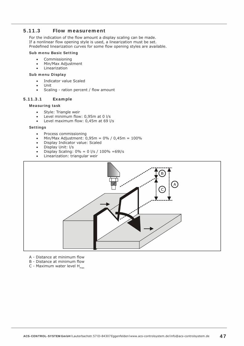
5 .11 .3 Flow measurementFor the indication of the flow amount a display scaling can be made.If a nonlinear flow opening style is used, a linearization must be set.Predefined linearization curves for some flow opening styles are available.
Sub menu Basic Setting
• Commissioning• Min/Max Adjustment• Linearization
Sub menu Display
• Indicator value Scaled• Unit• Scaling - ration percent / flow amount
5 .11 .3 .1 ExampleMeasuring task
• Style: Triangle weir• Level minimum flow: 0,95m at 0 l/s• Level maximum flow: 0,45m at 69 l/s
Settings
• Process commissioning• Min/Max Adjustment: 0,95m = 0% / 0,45m = 100%• Display Indicator value: Scaled• Display Unit: l/s• Display Scaling: 0% = 0 l/s / 100% =69l/s• Linearization: triangular weir
A - Distance at minimum flowB - Distance at minimum flowC - Maximum water level Hmax

ACS-CONTROL-SYSTEM GmbH l Lauterbachstr. 57 l D-84307 Eggenfelden l www.acs-controlsystem.de l [email protected]
5 .12 Software historyVersion Date Modifications4.1.0 07/2017 Original version

ACS-CONTROL-SYSTEM GmbH l Lauterbachstr. 57 l D-84307 Eggenfelden l www.acs-controlsystem.de l [email protected] 49
6 Service6 .1 Maintenance
The device is free of maintenance.
Special substances can lead to solid coatings on the sensor. Seized depositions can lead to faulty measurement results.
In the case of coat forming liquids the sensor must be regularly cleaned e.g. with clear water. Don’t use sharp resp. hard tools or aggressive chemicals for cleaning.
6 .2 DismountingAttention – Risk of burns!Let the device cool down sufficiently fore dismounting itDuring dismounting there is a risk of dangerously hot media escaping.
Attention – Risk of injury!Dismount the device only when the system is pressureless.During dismounting there is a risk of fast escaping media resp. pressure blow.
6 .3 RepairA repair may only be carried out by the manufacturer.
If the device is sent back for repair, the following information’s must be enclosed:• An exact description of the application.• The chemical and physical characteristics of the product.• A short description of the occurred error.
6 .4 ReturnBefore returning the device, the following measures must be performed:
• All adhesive product residues must be removed. This is especially important, if the product is unhealthily, e.g. caustic, toxic, carcinogenic, radioactive etc.
• A returning must be refrained, if it is not possible by 100% to remove the unhealthily product completely, because e.g. it is penetrate into cracks or is diffused through plastic.
6 .5 DisposalDispose of instrument components and packaging materials in an environmentally compatible way and in accordance with the country-specific waste disposal regulations.
This instrument is not subject to the WEEE directive and the respective national laws. Hence, pass the instrument directly on to a specialized recycling company and do not use the municipal collecting points. These may be used only for privately used products according to the WEEE directive.

ACS-CONTROL-SYSTEM GmbH l Lauterbachstr. 57 l D-84307 Eggenfelden l www.acs-controlsystem.de l [email protected]
7 Technical Data7 .1 Auxiliary power supplySupply voltage US Setting output 0/4...20 mA
9..30 VDC, reverse polarity protectedSetting output 0…10 V14..30 VDC, reverse polarity protected
Residual ripple UPP ≤ 2VPP / USmin ≤ US ≤ USmax
Supply current IIn Setting output 0/4...20 mA≤ 110 mA (US = 9 V / IO/S1/S2/S3/S4 0mA / Bluetooth Off)≤ 130 mA (US = 9 V / IO/S1/S2/S3/S4 0mA / Bluetooth On)≤ 70 mA (US = 30 V / IO/S1/S2/S3/S4 0mA / Bluetooth Off)≤ 80 mA (US = 30 V / IO/S1/S2/S3/S4 0mA / Bluetooth On)Setting output 0…10 V≤ 65 mA (US = 14 V / UO/S1/S2/S3/S4 0mA / Bluetooth Off)≤ 80 mA (US = 14 V / UO/S1/S2/S3/S4 0mA / Bluetooth On)≤ 50 mA (US = 30 V / UO/S1/S2/S3/S4 0mA / Bluetooth Off)≤ 60 mA (US = 30 V / UO/S1/S2/S3/S4 0mA / Bluetooth On)
7 .2 Input7 .2 .1 Measuring range type 02 – 2mMeasuring range ≤ 2m Blocking distance BD ≤ 0,15m (typ. 0,06m)Operating frequency 125kHzEmitting angle α 10° ±2° (-3dB)Detection radius rx rx = 0,087m (Lx = 1,0m / α = 10°)
rx = 0,175m (Lx = 2,0m / α = 10°)Pulse rate tp (meas. cycle time) 5Hz (200ms)
2,5Hz (400ms)1,25Hz (800ms)
7 .2 .2 Measuring range type 05 – 5mMeasuring range ≤ 5m Blocking distance BD ≤ 0,20m (typ. 0,15m)Operating frequency 75kHzEmitting angle α 14° ±2° (-3dB)Detection radius rx rx = 0,307m (Lx = 2,5m / α = 14°)
rx = 0,614m (Lx = 5,0m / α = 14°)Pulse rate tp (meas. cycle time) 2,5Hz (400ms)
1,25Hz (800ms)0,625Hz (1600ms)
7 .2 .3 Measuring range type 08 – 8mMeasuring range ≤ 8m Blocking distance BD ≤ 0,30m (typ. 0,19m)Operating frequency 50kHzEmitting angle α 10° ±2° (-3dB)Detection radius rx rx = 0,491m (Lx = 4,0m / α = 10°)
rx = 0,700m (Lx = 8,0m / α = 10°)Pulse rate tp (meas. cycle time) 1,667Hz (500ms)
0,833Hz (1000ms)0,417Hz (2000ms)
ACS-CONTROL-SYSTEM GmbH l Lauterbachstr. 57 l D-84307 Eggenfelden l www.acs-controlsystem.de l [email protected] 51
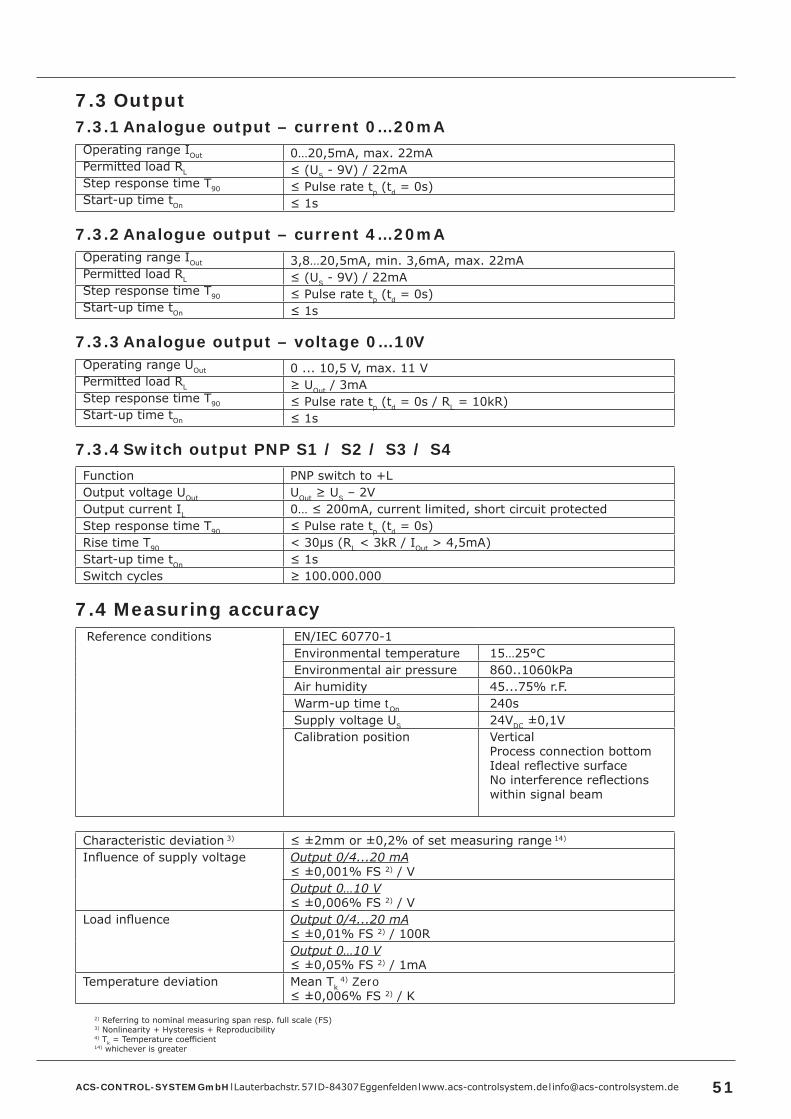
7 .3 Output7 .3 .1 Analogue output – current 0…20mAOperating range IOut 0…20,5mA, max. 22mAPermitted load RL ≤ (US - 9V) / 22mAStep response time T90 ≤ Pulse rate tp (td = 0s)Start-up time tOn ≤ 1s
7 .3 .2 Analogue output – current 4…20mAOperating range IOut 3,8…20,5mA, min. 3,6mA, max. 22mAPermitted load RL ≤ (US - 9V) / 22mAStep response time T90 ≤ Pulse rate tp (td = 0s)Start-up time tOn ≤ 1s
7 .3 .3 Analogue output – voltage 0…10VOperating range UOut 0 ... 10,5 V, max. 11 VPermitted load RL ≥ UOut / 3mAStep response time T90 ≤ Pulse rate tp (td = 0s / RL = 10kR)Start-up time tOn ≤ 1s
7 .3 .4 Switch output PNP S1 / S2 / S3 / S4Function PNP switch to +LOutput voltage UOut UOut ≥ US – 2VOutput current IL 0… ≤ 200mA, current limited, short circuit protectedStep response time T90 ≤ Pulse rate tp (td = 0s)Rise time T90 < 30µs (RL < 3kR / IOut > 4,5mA)Start-up time tOn ≤ 1sSwitch cycles ≥ 100.000.000
7 .4 Measuring accuracyReference conditions EN/IEC 60770-1
Environmental temperature 15…25°CEnvironmental air pressure 860..1060kPaAir humidity 45...75% r.F.Warm-up time tOn 240sSupply voltage US 24VDC ±0,1VCalibration position Vertical
Process connection bottomIdeal reflective surfaceNo interference reflections within signal beam
Characteristic deviation 3) ≤ ±2mm or ±0,2% of set measuring range 14)
Influence of supply voltage Output 0/4...20 mA≤ ±0,001% FS 2) / VOutput 0…10 V≤ ±0,006% FS 2) / V
Load influence Output 0/4...20 mA≤ ±0,01% FS 2) / 100ROutput 0…10 V≤ ±0,05% FS 2) / 1mA
Temperature deviation Mean Tk 4) Zero
≤ ±0,006% FS 2) / K2) Referring to nominal measuring span resp. full scale (FS)3) Nonlinearity + Hysteresis + Reproducibility4) Tk = Temperature coefficient14) whichever is greater

ACS-CONTROL-SYSTEM GmbH l Lauterbachstr. 57 l D-84307 Eggenfelden l www.acs-controlsystem.de l [email protected]
7 .5 Interface BluetoothVersion Bluetooth 2.1 + EDRSpecification Class 2Transmit power ≤ 2,5mW/4dBmRange ≤ 10m
7 .6 Data memoryMemory size ≥ 500.000 measuring valuesMemory system Ring memoryMemory rate 1…99999s
7 .7 ClockCycle accuracy ≤ ±1 minute / monthBattery run time ≥ 10 yearsHold-up timebattery-free system
≥ 1 minute
7 .8 Process conditionsProcess temperature -40°C…+85°CProcess pressure -0,3…2 bar
7 .9 Environmental conditionsEnvironmental temperature -20°C...+70°C
LimitationBacklight LCD ≥ 60% >> -20°C...+60°CBacklight LCD ≥ 80% >> -20°C...+50°C
Protection IP65/IP67 (EN/IEC 60529)Climatic classification 4K4H (EN/IEC 60721-3-4)Shock classification 15g [11ms] (EN/IEC 60068-2-27)Vibration classification 4g [10…2000 Hz] (EN/IEC 60068-2-6)EM compatibility Operation device class B / Industrial range (EN/IEC 61326)Tightening torque ≤ 50NmWeight Measuring range 02 – 2m
0,6kgMeasuring range 05 – 5m1,0kgMeasuring range 08 – 8m1,2kg
7 .10 Materials - process wettedSensor PVDFProcess connection Steel 1.4404/316L
Steel 1.4571/316TiGaskets EPDM – ethylene-propylene-dienmonomere
7 .11 Materials - not process wettedTerminal enclosure CrNi-steelControl panel surface PESElectrical connection part Device plug PURPressure compensation element Acrylic copolymerGaskets FPM – fluorelastomere (e.g. Viton®)
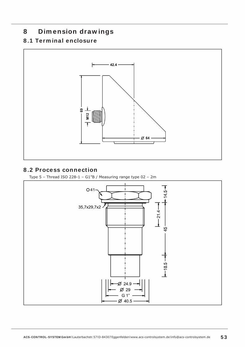
ACS-CONTROL-SYSTEM GmbH l Lauterbachstr. 57 l D-84307 Eggenfelden l www.acs-controlsystem.de l [email protected] 53
8 Dimension drawings8 .1 Terminal enclosure
8 .2 Process connectionType 5 – Thread ISO 228-1 – G1”B / Measuring range type 02 – 2m

ACS-CONTROL-SYSTEM GmbH l Lauterbachstr. 57 l D-84307 Eggenfelden l www.acs-controlsystem.de l [email protected]
Type 7 – Thread ISO 228-1 – G1½”B / Measuring range type 05 – 5m
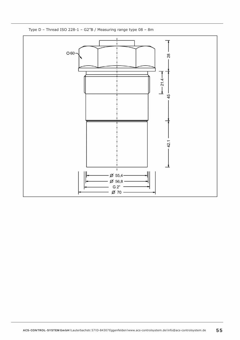
ACS-CONTROL-SYSTEM GmbH l Lauterbachstr. 57 l D-84307 Eggenfelden l www.acs-controlsystem.de l [email protected] 55
Type D – Thread ISO 228-1 – G2”B / Measuring range type 08 – 8m

Sonicont® C SUSN4S V3P 000S
ACS-CONTROL-SYSTEM GmbH l Lauterbachstr. 57 l D-84307 Eggenfelden l www.acs-controlsystem.de l [email protected]
Installation material and connection cable are not enclosed in contents of delivery .
TypeUSN4S Standard
Measuring system – material diaphragm (process wetted) / sensor type P PVDF / Piezo
Approval S Standard
Process connection 5 Thread ISO 228-1 – G1”B 7 Thread ISO 228-1 – G1½“B D Thread ISO 228-1 – G2“B Y others
Material process gaskets (process wetted) 3 EPDM – ethylene-propylene-dienmonomere
Material process connection (process wetted) V CrNi-steel
Material terminal enclosure C CrNi-steel
Measuring range 02 2 m 05 5 m 08 8 m YY Special measuring range
Electronic – output M 1x signal 0/4…20mA-0…10V, supply 24VDC K 1x signal 0/4…20mA-0…10V, 2x switch PNP, supply 24VDC R 1x signal 0/4…20mA-0…10V, 4x switch PNP, supply 24VDC
Electronic – function 0 without 1 Bluetooth-Interface 2 Data logger with time stamp, battery powered 3 Bluetooth-Interface / Data logger with time stamp, battery powered Y others
Process temperature 0 Standard –40°C…+85°C
0
0
Electrical connection S Plug M12x1
9 Ordering information9 .1 Order code

ACS-CONTROL-SYSTEM GmbH l Lauterbachstr. 57 l D-84307 Eggenfelden l www.acs-controlsystem.de l [email protected] 57
9 .2 Additional optionsFor the device additional options are available.The respective abbreviation subsequently follows the order code.
• SF LABS-free, silicone-free / paint compatible version• ML Measurement point designation / TAG – Laser marking• KL Customer label on device – Laser marking• TN Type label neutral• MZ Material test certificate – EN10204 3.1• KF Configuration / Preset• WK Factory calibration – calibration certificate
9 .3 AccessoriesAccessories are not content of delivery of the device and must be ordered separately.
9 .3 .1 Installation materialA wide range of accessories for device installation is constantly available, e.g.• Welding sockets• Welding flanges• Blind flanges• Flanges with thread• Reductions• Tube nuts• Siphons• Marking plate measuring point, laser marked• etc.
9 .3 .2 Connection cable / Cable boxConnection cable M12x1, material PUR, shielded• LKZ04##PUR-AS 4-pole, straight, ## = length 2…30m• LKW04##PUR-AS 4-pole, angled, ## = length 2…30m• LKZ05##PUR-AS 5-pole, straight, ## = length 2…30m• LKW05##PUR-AS 5-pole, angled, ## = length 2…30m• LKZ08##PUR-AS 8-pole, straight, ## = length 2…30m• LKW08##PUR-AS 8-pole, angled, ## = length 2…30m
Other connection cables, e.g. other material, unshielded or integrated LED are available.
Cable box M12x1• BKZ0412-VA 4-pole• BKZ0512-VA 5-pole• BKZ0812-VA 8-pole