(some) mdi engineering aspects at ilc & clic...the first important measure will be to choose a...
TRANSCRIPT

(Some) MDI Engineering Aspects
at ILC & CLIC
A. Hervé / ETH-ZürichTogether with ILC and CLIC MDI Groups
CLIC Meeting-14 January 2011

Alain Hervé, CLIC-Meeting, 14 January 2011 2
This is a slightly updated version
of the talk presented at
IWLC10
on Friday 22 Oct. 2010

3
Content of the talk
I will not try to cover all aspects of MDI, please refer
to talks of the working group chairmen:
• Andrei Seryi (John Adams Institute) for ILC.
• Lau Gatignon (CERN) for CLIC
I will introduce:
• the main features of MDI for ILC,
• then look at CLIC, pointing out what is different
and why,
• not forgetting at the end the challenges of the
Push-Pull.
Alain Hervé, CLIC-Meeting, 14 January 2011

4
MDI at a LC is governed by
• A small L* (3.5 m) to maximize luminosity, and thus
the last machine elements penetrate inside the
detector.
• A small size of the beams (nm level), requiring
extreme stability of the BDS.
• An active pre-alignment system is needed to
correct for slow drifts
• A beam fast Feed Back system is also mandatory
to correct movements at higher frequencies.
Alain Hervé, CLIC-Meeting, 14 January 2011

5
MDI @ ILC
Alain Hervé, CLIC-Meeting, 14 January 2011

6
SiD: QD0 penetrates inside the experiments
QD0QF
2 concepts
SiD and ILC
Retained after LoIs

7
• Position of the BDS elements and QD0 aligned at ± 10 μm rms
w.r.t ideal straight line.
For the last 500 meters on each side of IP
Pre-alignment system,
example of CLIC (H. Maynaud et al. /CERN)
Alain Hervé, CLIC-Meeting, 14 January 2011
(active) prealignment
system is mandatory

Philip Burrows
CLIC MDI Meeting 6/11/09
8
Intra-train feedback system
• Last line of defence against relative beam misalignment
• BPM measures vertical deviation of outgoing beam
• Fast kicker correct vertical position of beam incoming to IR
(JAI/Oxford, Valencia, CERN, DESY, KEK, SLAC)

QD0 in ILC (Bret Parker / BNL)Very involved coil package at 1.8 K
⇐ Field on axis
is reduced and
luminosity is
recovered

DiD and anti DiD at ILC(Dipole Integrated Detector)
➽ not adopted at CLIC
Alain Hervé, CLIC08 Workshop, 16 October 2008 10
DiD on-axis field

ILC typical beam line components
IP
1st conical tube
DN150CF flange
Ion pump integrated
in beam pipe
Pre-pumping port
+ gauges
Special gate valve
BPM
QD0 Cryostat, Coils at 1.8K
Kicker
Valves for
Push-Pull
Common break point at
9m from IP
Bellows(ILD)
Alain Hervé, CLIC-Meeting, 14 January 2011

QF
QD0 @ 1.8 K
Cam/support
SiD supports the QD0 from the endcap door
using a cam/support system
BPM
Kicker
IP
This is based on SLD Experience
Alain Hervé, CLIC-Meeting, 14 January 2011

QD0 support
ILD: QDO supported from the tunnel wall(Matthieu Joré / LLR)
• Using 2 square tubes :
– Internal QD0 support tube
• Attached to machine tunnel
• Good coherency with machine vibrations and high natural frequency
– External FCals support tube
• Could be supported from pillar and tension rods
5 mm gap between
both supports
Machine concrete
Pillar
Tension rods
(from an idea of Hiroshi Yamaoka at KEK,
idea also used by CLIC detectors)
Alain Hervé, CLIC-Meeting, 14 January 2011

14
Vibration consideration for ILC
and influence of beam Feed-Back system(P. Burrows et al. / JAI)
• For ILC, the fast beam Feed Back system
developed at JAI is very efficient and can have a
reach of 300 nm.
• Thus the needed stability of the QD0 support is
around 50 nm or better.
• First vibration measurements in the CMS area have
shown that this is possible.
Alain Hervé, CLIC-Meeting, 14 January 2011

15
Vibration consideration from CMS
Geophones
Top 100 nm
Ground 5 nm
Measurements at KEK
on BELLE (Hiroshi
Yamaoka) have also
shown a degradation
of performances when
moving up along the
yoke.
➽ 50 nm at beam
level look reasonable.
Vibrations on ground and top of CMS
central barrel YB0 in ‘Quiet
experimental area’ end of 2009
(Artoos, Guinchard et al.)
Alain Hervé, CLIC-Meeting, 14 January 2011

16
MDI @ CLIC
Alain Hervé, CLIC-Meeting, 14 January 2011

17
Introduction - II
• CLIC MDI studies have benefitted of a jump-start
due to the studies done for ILC.
• However two parameters are really different and
make the problem more difficult:
• The vertical size of the beam is smaller, typically
1 nm compared to 5 nm in ILC
• The beam time structure is unfavorable and the
reach of the beam Feed-Back system is reduced.
Alain Hervé, CLIC-Meeting, 14 January 2011

IP-Feed-Back Systems (Phil Burrows and J. Resta-Lopez / JAI)
ILC (500 GeV)
• Beam time structure: – Train repetition rate: 5 Hz
– Bunch separation: 369.2 ns
– Train length: 969.15 µs
• Intra-train (allows bunch-to-bunch correction)
• Digital FB processor (allows FPGA programming)
CLIC (3 TeV)
• Beam time structure:– Train repetition rate: 50 Hz
– Bunch separation: 0.5 ns
– Train length: 0.156 µs
• Intra-train (but not bunch-to-bunch)
• All-analogue FB processor
For CLIC, intra-train FB corrections at the IP are especially
challenging
• bunch separation about 740 times smaller than for the ILC
• bunch train length about 6200 times shorter than for the ILC
Alain Hervé, CLIC-Meeting, 14 January 2011

19
Stability of the QD0 mechanical support
• If we move backward in the CLIC stabilization budget:
• Ultimate stabilization to obtained the luminosity is
0.15 nm @ 4Hz at IP.
• Thus, before the intra-train Fast Feed-Back
system, a stability of 0.5 nm is needed.
• Thus, before the active stabilization system,
5 nm or less are needed for the stability of the QD0
mechanical support.
This is a factor 10 w.r.t. ILC!
Alain Hervé, CLIC-Meeting, 14 January 2011

20
To obtain the utmost beam stability
for CLIC additional efforts are needed.
(In addition to the active pre-alignment and
intra-train Fast Feed-Back systems)
Alain Hervé, CLIC-Meeting, 14 January 2011

1-Use a permanent magnet QD0(Michele Modena et al. / CERN)
21
This is to suppress vibrations due to cooling and thin
suspensions of the cold mass. The use of Permendur
imposes to have H ≈ 0.
Thus a non negligible anti-
solenoid coil, fixed on the
endcap, has to be foreseen
outside the support tube.
This will also reduce the field
seen by the beam and recover
luminosity loss
⇐ (Barbara Dalena).
Alain Hervé, CLIC-Meeting, 14 January 2011

22
2-Decouple the QD0 support
from the experiment
This has been shown previously: the most stable
element is the tunnel floor and not the yoke of the
experiment.
Top 100 nm
Ground 5 nm
⇐Measurements in
CMS area
end of 2009.
Alain Hervé, CLIC-Meeting, 14 January 2011

23
3-Minimize the length of the support tube
• It is clear that the length of the support tube must
be minimized as flexion is involved.
• This can be obtained by abandoning the opening
on IP.
• Anyway not much maintenance can be done on IP,
and if the Push-Pull operation is working well, it is
more efficient to repair in the garage area.
Alain Hervé, CLIC-Meeting, 14 January 2011

24
Minimize the length of the support tube
Platform
Pacman -> Pacrings
End of
TunnelEnd of
Tunnel
Alain Hervé, CLIC-Meeting, 14 January 2011

View of the shielding Packring arrangement
Alain Hervé, CLIC08 Workshop, 16 October 2008 25

Clearly CLIC experiments
must have the same length!
Alain Hervé, CLIC08 Workshop, 16 October 2008 26
This has been achieved for CLIC_SiD
and CLIC_ILD at the cost of some active
coils in CLIC_ILD pacrings

7 May 2010 H. Gerwig - 13th MDI 27
HallExperiment 1
HallExperiment 2
Transfer tunnel with IP
AlignmentTunnel
Discussed withJ. Osborne & M. Gastal
Excavated volume is less than for a standard hall
Flat walls on tunnel sides
19/10/2010 27
This governs the proposal
for CLIC Experimental Area(H. Gerwig / CERN)

28
• The idea is to decouple and stabilize the support of
QD0 and QF1.
• It must be connected to the active pre-alignment
system to correct or low freq. (< 1 Hz) movements.
4-Support the QD0 and QF1
from a Pre-Isolator(Andrea Gaddi et al. / CERN)
Alain Hervé, CLIC-Meeting, 14 January 2011

Pre-isolator @ CLIC
QD0 QF1
Pre-isolator slab
(can be extracted as one
complete unit) through the
experimental area
Accelerator
tunnel
IP
Alain Hervé, CLIC-Meeting, 14 January 2011

Pre-isolator @ CLIC
Alain Hervé, CLIC08 Workshop, 16 October 2008 30
Low freq. air
springs

5-Adopt the solution of a double tube
Thank You !
31Alain Hervé, CLIC-Meeting, 14 January 2011
(Timing!)

The outer support-tube allows access
Alain Hervé, CLIC08 Workshop, 16 October 2008 32

Double support-Tube and anti-Solenoid
Alain Hervé, CLIC08 Workshop, 16 October 2008 33

Detail supporting of double Support-Tube
Alain Hervé, CLIC08 Workshop, 16 October 2008 34

35
➽ It has to be implemented inside the limited space and
environment of the support tube, more integration effort is
needed.
(Andrea Jeremie et al. Annecy)
Proof of principle has been obtained in the lab.
6-Use a sophisticated active
Stabilization System
Alain Hervé, CLIC-Meeting, 14 January 2011
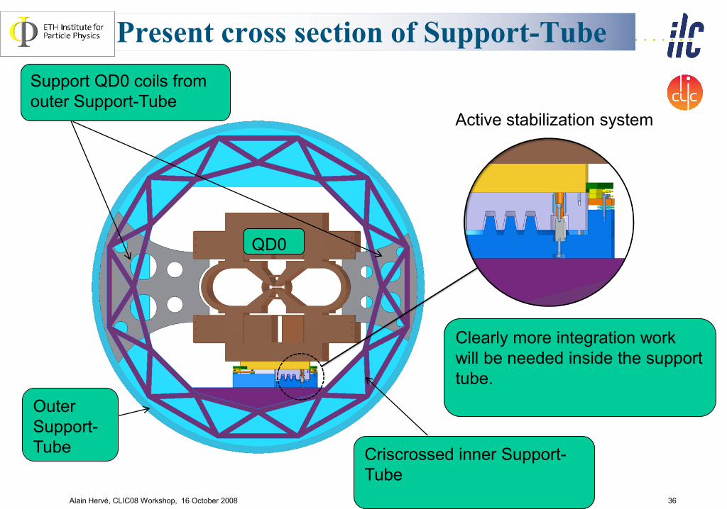
Present cross section of Support-Tube
Alain Hervé, CLIC08 Workshop, 16 October 2008 36
Active stabilization system
Clearly more integration work
will be needed inside the support
tube.
Support QD0 coils from
outer Support-Tube
Outer
Support-
Tube Criscrossed inner Support-
Tube
QD0

37
Obtaining the utmost beam stability
All these efforts will pay but it
must not be forgotten that:
➽ The first important measure will be to choose a
‘quiet’ site with respect to cultural noise and
design a ‘quiet’ area with respect to technical
noise.
Alain Hervé, CLIC-Meeting, 14 January 2011

38
Push-Pull Considerations
Alain Hervé, CLIC-Meeting, 14 January 2011

39
Reminder
• The push-pull project, to exchange quickly two
experiments on IP, is a very ambitious one.
• In size of loads to be moved > 10’000 tons, number
of movements, 6 per year ➽ 180 over 15 years.
• It is demanding considering: environment, final
precision, and time constraints, (full exchange in less
than three or four days) including precise
realignment.
• But, one must always be able to extract sideway an
experiment for maintenance every year (like Opal,
Delphi, Aleph… on LEP).
• Thus the Push-Pull project is just a more
demanding normal maintenance displacement
scenario!Alain Hervé, CLIC-Meeting, 14 January 2011

detector
B
may be
accessible
during run
accessible
during run Platform for electronic
and services. Shielded.
Moves with detector.
Isolate vibrations.
Starting point (~2006) push-pull for ILC
Proposal by A. SeryiProposal by A. Seryi
first Power Pointfirst Power Point
Proposal by A. SeryiProposal by A. Seryi
first Power Pointfirst Power Point
detector
A

Alain Hervé, CLIC08 Workshop, 16 October 2008 41
SiD and ILD with or without a platform ?
( M. Oriunno / SLAC )
As the idea of push-pull has been
introduced during the LoI process, ILD
has adopted a platform, however SiD
has chosen to move directly on the
ground.
Presently the two solutions are not
compatible, and discussion are going on
and a work plan has been adopted to
converge fairly quickly.
With
Without
Alain Hervé, CLIC-Meeting, 14 January 2011

42
Push-Pull for CLIC detectors
H. Gerwig / A Gaddi19/10/2010 42
CLIC has chosen to use
platforms from the start

This governs the geometry of exp area
Alain Hervé, CLIC08 Workshop, 16 October 2008 43

First concept of experimental area
Alain Hervé, CLIC08 Workshop, 16 October 2008 44

45
Platform/ Airpad consideration
• The platform solution shows all its advantages
when used in conjunction with airpads (as opposed
to rollers), because airpads:
• have no preferred direction of movement.
• allow an easy repair of the rail / support system,
removing the high risk of staying blocked.
• allow a fast and safe positioning of the
experiment on beam.
Alain Hervé, CLIC-Meeting, 14 January 2011

Alain Hervé, CLIC08 Workshop, 16 October 2008 46
Load will arrive off-center and off-axis
Alain Hervé, CLIC-Meeting, 14 January 2011

Alain Hervé, CLIC08 Workshop, 16 October 2008 47
2D movement and a rotation are needed
this is very difficult with rollers
Alain Hervé, CLIC-Meeting, 14 January 2011

Alain Hervé, CLIC08 Workshop, 16 October 2008 48
With Airpads a simple positive indexing
mechanism is possible giving ≈mm precision
Alain Hervé, CLIC-Meeting, 14 January 2011

Alain Hervé, CLIC08 Workshop, 16 October 2008 49
The final precision could be +-1 mm
and +-0.1 mrad.
Alain Hervé, CLIC-Meeting, 14 January 2011

50
Vertical adjustment
• Exchanging 10’000 ton experiments will induce a
settlement of the whole experimental zone and
adjacent machine tunnels.
• One can expect vertical movements in the
millimeter range that can take one month to recover.
• This kind of slow drift must also be taken care of by
the active pre-alignment system.
Alain Hervé, CLIC-Meeting, 14 January 2011

51
Moving towards a common solution
for the Push-Pull system
• ILD is making studies to justify that it cannot move
without a platform.
• At the same time, it must be shown that the use of
a platform is not detrimental to SiD that has chosen
to support the QD0s from the endcap doors.
•CLIC must also demonstrate that the lay-out of the
experimental area will allow to meet the
specification.
Alain Hervé, CLIC-Meeting, 14 January 2011

52
Vibration consideration at ILC
moving towards a common solution
• The priority is to develop credible simulation tools,
and Marco Oriunno at SLAC for SiD and Hitoshi
Yamaoka at KEK for ILD have started extensive
studies.
• However, one must make sure that the results of
simulations are in agreement with reality and
extensive benchmarking is required.
Alain Hervé, CLIC-Meeting, 14 January 2011

53
1st Mode, 2.38 Hz 2nd Mode, 5.15 Hz 3rd Mode, 5.45 Hz
4th Mode, 6.53 Hz 5th Mode, 10.42 Hz 6th Mode, 13.7 Hz
Vertical motion
SiD Free Vibration Mode (example)
M. Oriunno / SLAC

54
Response amplitude (Comparison of computations and measurements)
QCS-t
QCS-s
Coil-t
Coil-s
Measurements@QCS-sCalculation: damp=0.5%
MeasurementCalculation:
H. Yamaoka / KEK

55
Vibration considerations
connected to the platform
• The CMS plug is a good example of what can be a
Push-Pull platform, it has the necessary rigidity.
• It can be used to benchmark the simulation
programs.
• First vibration measurements have been carried out
end of 2009.
• End Oct. a new measurement campaign has been
performed (K. Artoos, M. Guinchard et al.) for SiD.
Alain Hervé, CLIC-Meeting, 14 January 2011

A. Hervé - 12 July 2007 ILC-IRENG07-0712-4345 56
The 2000-ton CMS Plug has been used for
the Heavy Lifting operation
Plug
1
CMS plugCMS plug

Alain Hervé, CLIC08 Workshop, 16 October 2008 57
The CMS Plug finished looks neat!
20 m

Alain Hervé, CLIC08 Workshop, 16 October 2008 58
Steel reinforcement of CMS Plug
➽ Clearly models need benchmarking to evaluate
damping coefficient and Young’s modulus

59
Vibration consideration
connected to the platform
• The study of the CMS plug is a good example of
work that is in interest of both ILC and CLIC
(ILC is interested in the platform solution and CLIC
has directly engaged on using two platforms for the
Push-Pull operation.)
Alain Hervé, CLIC-Meeting, 14 January 2011

60
Vibration and movements
connected to civil engineering
• LHC experimental areas for ATLAS and CMS are a
good example of how such systems behave in the
CERN geology.
• However, the level of the requirements for CLIC
necessitates to re-examine the situation of general
movements, ground vibration and micro-seisms.
• A first discussion with tunneling experts has been
organized by J. Osborne mid February.
Alain Hervé, CLIC-Meeting, 14 January 2011

61John Osborne : GS-SE
•At the Linear Collider Workshop in Oct 2009 in Geneva, it was agreed in
the MDI subgroup that further in-depth civil engineering studies should be
undertaken to study the feasibility of the proposed detector movement
system and experimental area layout
•As such, a one day workshop is being set-up at CERN to see how best
this issue can be tackled on 16th February 2011
•An expert tunneling firm from London (ARUP) are participating in this first
meeting
•Goals of the meeting :
• Review the experience learnt from LHC detector assembly,
installation and operational movements
• Review existing data on ground movements / stability / vibration
issues
• Plan how best to verify the feasibility of the concrete platform
concept and potential ground movements that could be induced by
detector exchange with push-pull operation
• Share knowledge with ILC
Civil Engineering Studies for CLIC Experimental
Layout

62
Conclusions
Alain Hervé, CLIC-Meeting, 14 January 2011

63
Conclusions-I
• To maximize LC luminosity the last focusing element
must penetrate inside the experiment to achieve a low L*.
• The small size of the beams imposes to use an active
pre-alignment system against slow drifts.
• In addition a beam Fast Feed Back system is needed to
correct for movements at higher frequencies.
• This is sufficient for ILC that benefits from a favorable
beam time structure.
• For CLIC that has smaller beam size and an unfavorable
beam time structure, supplementary efforts are needed.
Alain Hervé, CLIC-Meeting, 14 January 2011

64
Conclusions-II
• The Push-Pull system is a very demanding project and
there is no example to refer to.
• CLIC has adopted a platform to move each experiment.
• ILC concepts are in discussion to adopt a common
solution and a working plan has been drafted.
• It is important to make sure that the platform solution
does not worsen the stability of the QD0s that, in SiD, are
supported from the endcap doors.
Alain Hervé, CLIC-Meeting, 14 January 2011

65
Conclusions-III
• The CMS plug is a good example of what a platform
could be.
• It can be used to benchmark simulation models.
• Further vibration measurements on the CMS plug will be
needed.
• These measurements are also in the interest of the
CLIC project.
• The studies of platform and associated vibrations could
be part of the ILC/CLIC Collaboration.
Alain Hervé, CLIC-Meeting, 14 January 2011

66
Conclusions-IV
• The MDI studies are now mature for both ILC and CLIC.
• More detailed studies and tests are needed for CLIC due
to the level of stability required for the QD0.
• More studies are needed from the civil engineering point
of view to ascertain slow movements and vibrations (starts
with meeting mid-Feb.).
• The requirements are different enough that (apart maybe
the Push-Pull system proper) solutions adopted by ILC
and CLIC, although similar, are fairly different and are
likely to stay different.
Alain Hervé, CLIC-Meeting, 14 January 2011

Thank You !
67Alain Hervé, CLIC-Meeting, 14 January 2011