solving problems in food engineering
TRANSCRIPT


Solving Problems in Food Engineering

Stavros Yanniotis, Ph.D.Author
Solving Problems inFood Engineering

Stavros Yanniotis, Ph.D.Department of Food Science and TechnologyAgricultural University of AthensAthens, Greece
ISBN: 978-0-387-73513-9 eISBN: 978-0-387-73514-6
Library of Congress Control Number: 2007939831
# 2008 Springer Science+Business Media, LLCAll rights reserved. This workmay not be translated or copied in whole or in part without the writtenpermission of the publisher (Springer Science+Business Media, LLC., 233 Spring Street, NewYork, NY10013, USA), except for brief excerpts in connection with reviews or scholarly analysis.Use in connection with any form of information storage and retrieval, electronic adaptation,computer software, or by similar or dissimilar methodology now known or hereafter developed isforbidden.The use in this publication of trade names, trademarks, service marks, and similar terms, even if theyare not identified as such, is not to be taken as an expression of opinion as to whether or not they aresubject to proprietary rights.
Printed on acid-free paper
9 8 7 6 5 4 3 2 1
springer.com

‘‘Tell me and I will listen,Show me and I will understand
Involve me and I will learn’’
Ancient Chinese Proverb

Preface
Food engineering is usually a difficult discipline for food science studentsbecause they are more used to qualitative rather than to quantitative descrip-tions of food processing operations. Food engineering requires understandingof the basic principles of fluid flow, heat transfer, andmass transfer phenomenaand application of these principles to unit operations which are frequently usedin food processing, e.g., evaporation, drying, thermal processing, cooling andfreezing, etc. The most difficult part of a course in food engineering is oftenconsidered the solution of problems. This book is intended to be a step-by-stepworkbook that will help the students to practice solving food engineeringproblems. It presumes that the students have already studied the theory ofeach subject from their textbook.
The book deals with problems in fluid flow, heat transfer, mass transfer,and themost common unit operations that find applications in food processing,i.e., thermal processing, cooling and freezing, evaporation, psychometrics, anddrying. The book includes 1) theoretical questions in the form ‘‘true’’ or ‘‘false’’which will help the students quickly review the subject that follows (the answersto these questions are given in the Appendix); 2) solved problems; 3) semi-solved problems; and 4) problems solved using a computer. With the semi-solved problems the students are guided through the solution. The main stepsare given, but the students will have to fill in the blank points. With thistechnique, food science students can practice on and solve relatively difficultfood engineering problems. Some of the problems are elementary, but problemsof increasing difficulty follow, so that the book will be useful to food sciencestudents and even to food engineering students.
A CD is supplied with the book which contains solutions of problems thatrequire the use of a computer, e.g., transient heat and mass transfer problems,simulation of a multiple effect evaporator, freezing of a 2-D solid, drying, andothers. The objectives for including solved computer problems are 1) to give thestudents the opportunity to run such programs and see the effect of operatingand design variables on the process; and 2) to encourage the students to usecomputers to solve food engineering problems. Since all the programs in thisCD are open code programs, the students can see all the equations and the logicbehind the calculations. They are encouraged to see how the programs work
vii
and try to write their own programs for similar problems. Since food sciencestudents feel more comfortable with spreadsheet programs than with program-ming languages, which engineering students are more familiar with, all theproblems that need a computer have EXCEL1 spreadsheet solutions.
I introduce the idea of a digital SWITCH to start and stop the programswhen the problem is solved by iteration. With the digital SWITCH, we can stopand restart each program at will. When the SWITCH is turned off the programis not running, so that we can change the values of the input variables. Everytime we restart the program by turning the SWITCH on, all calculations startfrom the beginning. Thus it is easy to change the initial values of the inputvariables and study the effect of processing and design parameters. In the effortto make things as simple as possible, some of the spreadsheet programs may notoperate on some sets of parameters. In such cases, it may be necessary to restartthe program with a different set of parameters.
I am grateful to Dr H. Schwartzberg, who read the manuscripts and madehelpful suggestions. I will also be grateful to readers who may have usefulsuggestions, or who point out errors or omissions which obviously have slippedfrom my attention at this point.
Athens Stavros YanniotisMay 2007
viii Preface

Contents
Preface . . . . . . . . . . . . . . . . . . . . . . . . . . . . . . . . . . . . . . . . . . . . . . . . . . . . vii
1. Conversion of Units . . . . . . . . . . . . . . . . . . . . . . . . . . . . . . . . . . . . . . . . 1ExamplesExercises
2. Use of Steam Tables . . . . . . . . . . . . . . . . . . . . . . . . . . . . . . . . . . . . . . . . 5Review QuestionsExamplesExercises
3. Mass Balance . . . . . . . . . . . . . . . . . . . . . . . . . . . . . . . . . . . . . . . . . . . . . 11Review QuestionsExamplesExercises
4. Energy Balance . . . . . . . . . . . . . . . . . . . . . . . . . . . . . . . . . . . . . . . . . . . 21TheoryReview QuestionsExamplesExercises
5. Fluid Flow . . . . . . . . . . . . . . . . . . . . . . . . . . . . . . . . . . . . . . . . . . . . . . . 33Review QuestionsExamplesExercises
6. Pumps . . . . . . . . . . . . . . . . . . . . . . . . . . . . . . . . . . . . . . . . . . . . . . . . . . . 41TheoryReview QuestionsExamplesExercises
ix
7. Heat Transfer By Conduction . . . . . . . . . . . . . . . . . . . . . . . . . . . . . . . 55TheoryReview QuestionsExamplesExercises
8. Heat Transfer By Convection . . . . . . . . . . . . . . . . . . . . . . . . . . . . . . . 67TheoryReview QuestionsExamplesExercises
9. Heat Transfer By Radiation . . . . . . . . . . . . . . . . . . . . . . . . . . . . . . . . . 95Review QuestionsExamplesExercises
10. Unsteady State Heat Transfer . . . . . . . . . . . . . . . . . . . . . . . . . . . . . . 101TheoryReview QuestionsExamplesExercises
11. Mass Transfer By Diffusion . . . . . . . . . . . . . . . . . . . . . . . . . . . . . . . . 141TheoryReview QuestionsExamplesExercises
12. Mass Transfer By Convection . . . . . . . . . . . . . . . . . . . . . . . . . . . . . . 155TheoryReview QuestionsExamplesExercises
13. Unsteady State Mass Transfer . . . . . . . . . . . . . . . . . . . . . . . . . . . . . . 163TheoryReview QuestionsExamplesExercises
14. Pasteurization and Sterilization . . . . . . . . . . . . . . . . . . . . . . . . . . . . . 181Review QuestionsExamplesExercises
x Contents
15. Cooling and Freezing . . . . . . . . . . . . . . . . . . . . . . . . . . . . . . . . . . . . . 193Review QuestionsExamplesExercises
16. Evaporation . . . . . . . . . . . . . . . . . . . . . . . . . . . . . . . . . . . . . . . . . . . . 215Review QuestionsExamplesExercises
17. Psychrometrics . . . . . . . . . . . . . . . . . . . . . . . . . . . . . . . . . . . . . . . . . . 237Review QuestionsExamplesExercises
18. Drying . . . . . . . . . . . . . . . . . . . . . . . . . . . . . . . . . . . . . . . . . . . . . . . . 253Review QuestionsExamplesExercises
References . . . . . . . . . . . . . . . . . . . . . . . . . . . . . . . . . . . . . . . . . . . . . . . . . 273
Appendix: Answers to Review Questions . . . . . . . . . . . . . . . . . . . . . . . . . 275Moody diagram . . . . . . . . . . . . . . . . . . . . . . . . . . . . . . . . . . . . . . . . . 280Gurney-Lurie charts . . . . . . . . . . . . . . . . . . . . . . . . . . . . . . . . . . . . . 281Heisler charts . . . . . . . . . . . . . . . . . . . . . . . . . . . . . . . . . . . . . . . . . . . 284Pressure-Enthalpy chart for HFC 134a . . . . . . . . . . . . . . . . . . . . . . . 285Pressure-Enthalpy chart for HFC 404a . . . . . . . . . . . . . . . . . . . . . . . 286Psychrometric chart . . . . . . . . . . . . . . . . . . . . . . . . . . . . . . . . . . . . . . 287Bessel functions . . . . . . . . . . . . . . . . . . . . . . . . . . . . . . . . . . . . . . . . . 288Roots of d tand=Bi . . . . . . . . . . . . . . . . . . . . . . . . . . . . . . . . . . . . . . 290Roots of dJ1(d)-Bi Jo(d)=0 . . . . . . . . . . . . . . . . . . . . . . . . . . . . . . . . 291Roots of d cotd=1-Bi . . . . . . . . . . . . . . . . . . . . . . . . . . . . . . . . . . . . 292Error function . . . . . . . . . . . . . . . . . . . . . . . . . . . . . . . . . . . . . . . . . . 293
Index . . . . . . . . . . . . . . . . . . . . . . . . . . . . . . . . . . . . . . . . . . . . . . . . . . . . . . 295
Contents xi
Chapter 1
Conversion of Units
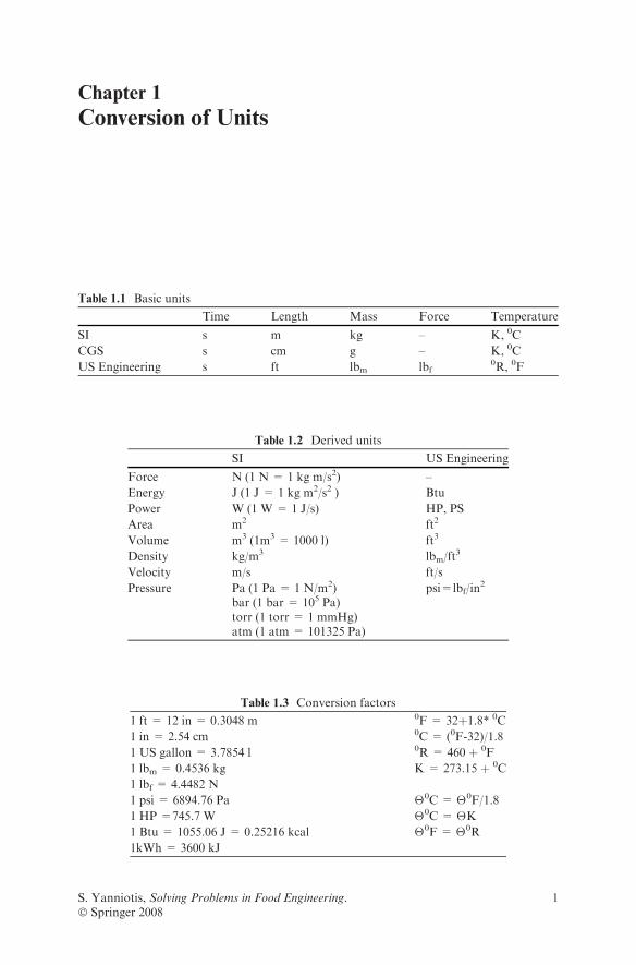
Table 1.1 Basic units
Time Length Mass Force Temperature
SI s m kg – K, 0C
CGS s cm g – K, 0C
US Engineering s ft lbm lbf0R, 0F
Table 1.2 Derived units
SI US Engineering
Force N (1 N = 1 kg m/s2) –
Energy J (1 J = 1 kg m2/s2 ) Btu
Power W (1 W = 1 J/s) HP, PS
Area m2 ft2
Volume m3 (1m3 = 1000 l) ft3
Density kg/m3 lbm/ft3
Velocity m/s ft/s
Pressure Pa (1 Pa = 1 N/m2)bar (1 bar = 105 Pa)torr (1 torr = 1 mmHg)atm (1 atm = 101325 Pa)
psi=lbf/in2
Table 1.3 Conversion factors
1 ft = 12 in = 0.3048 m 0F = 32þ1.8* 0C
1 in = 2.54 cm 0C = (0F-32)/1.8
1 US gallon = 3.7854 l 0R = 460 þ 0F
1 lbm = 0.4536 kg K = 273.15 þ 0C
1 lbf = 4.4482 N
1 psi = 6894.76 Pa �0C = �0F/1.8
1 HP =745.7 W �0C = �K
1 Btu = 1055.06 J = 0.25216 kcal �0F = �0R
1kWh = 3600 kJ
S. Yanniotis, Solving Problems in Food Engineering.� Springer 2008
1

Examples
Example 1.1
Convert 100 Btu/h ft2oF to kW/m2oC
Solution
100Btu
h ft2 8F¼100 Btu
h ft2 8F� 1055:06 J
1Btu� 1 kJ
1000 J� 1 h
3600 s
1ft2
0:3048mð Þ2
� 1:88F
18C� 1 kW1kJ=s
¼ 0:5678kW
m2 8C
Example 1.2
Convert 100 lb mol/h ft2 to kg mol/s m2
Solution
100lbmol
h ft2¼ 100
lbmol
h ft2� 0:4536 kgmol
lbmol� 1 h
3600 s� 1 ft2
0:3048mð Þ2¼ 0:1356
kgmol
sm2
Example 1.3
Convert 0.5 lbf s/ft2 to Pas
Solution
0:5lbf s
ft2¼ 0:5
lbf s
ft2� 4:4482N
lbf� 1 ft2
0:3048mð Þ21 Pa
1 N=m2ð Þ ¼ 23:94 Pa s
Exercises
Exercise 1.1
Make the following conversions:1) 10 ft lbf/lbm to J/kg, 2) 0.5 Btu/lbm
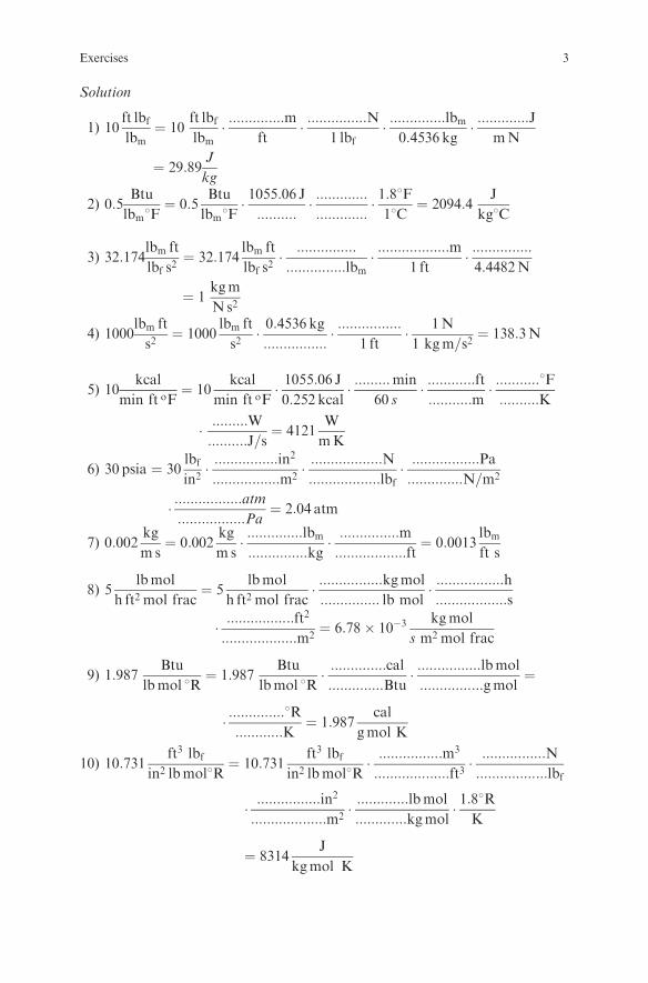
oF to J/kgoC, 3) 32.174 lbmft/lbfs2 to kgm/Ns2, 4) 1000 lbmft /s2 to N, 5) 10 kcal/min ft oF to W/mK, 6) 30 psia to atm,7) 0.002 kg/ms to lbmft s, 8) 5 lb mol/h ft2mol frac to kg mol/s m2 mol frac,9) 1.987 Btu/lbmol oR to cal/gmol K, 10) 10.731 ft3lbf/in
2lbmol oR to J/kgmolK
2 1 Conversion of Units
Solution
1) 10ft lbflbm¼ 10
ft lbflbm� ::::::::::::::m
ft� :::::::::::::::N
1 lbf� ::::::::::::::lbm
0:4536 kg� :::::::::::::J
mN
¼ 29:89J
kg
2) 0:5Btu
lbm8F¼ 0:5
Btu
lbm8F� 1055:06 J::::::::::
� ::::::::::::::::::::::::::
� 1:88F18C
¼ 2094:4J
kg8C
3) 32:174lbm ft
lbf s2¼ 32:174
lbm ft
lbf s2� :::::::::::::::
:::::::::::::::lbm� ::::::::::::::::::m
1 ft� :::::::::::::::4:4482N
¼ 1kgm
Ns2
4) 1000lbm ft
s2¼ 1000
lbm ft
s2� 0:4536 kg::::::::::::::::
� ::::::::::::::::1 ft
� 1N
1 kgm=s2¼ 138:3N
5) 10kcal
min ft oF¼ 10
kcal
min ft oF� 1055:06 J0:252 kcal
� :::::::::min
60 s� ::::::::::::ft:::::::::::m
� :::::::::::8F::::::::::K
� :::::::::W::::::::::J=s
¼ 4121W
mK
6) 30 psia ¼ 30lbfin2� ::::::::::::::::in
2
:::::::::::::::::m2� ::::::::::::::::::N::::::::::::::::::lbf
� :::::::::::::::::Pa::::::::::::::N=m2
� :::::::::::::::::atm:::::::::::::::::Pa
¼ 2:04 atm
7) 0:002kg
m s¼ 0:002
kg
m s� ::::::::::::::lbm:::::::::::::::kg
� :::::::::::::::m::::::::::::::::::ft
¼ 0:0013lbmft s
8) 5lbmol
h ft2 mol frac¼ 5
lbmol
h ft2 mol frac� ::::::::::::::::kgmol
::::::::::::::: lb mol� :::::::::::::::::h::::::::::::::::::s
� :::::::::::::::::ft2
:::::::::::::::::::m2¼ 6:78� 10�3
kgmol
s m2 mol frac
9) 1:987Btu
lbmol 8R¼ 1:987
Btu
lbmol 8R� ::::::::::::::cal::::::::::::::Btu
� ::::::::::::::::lbmol
::::::::::::::::gmol¼
� ::::::::::::::8R::::::::::::K
¼ 1:987cal
gmol K
10) 10:731ft3 lbf
in2 lbmol8R¼ 10:731
ft3 lbfin2 lbmol8R
� ::::::::::::::::m3
:::::::::::::::::::ft3� ::::::::::::::::N::::::::::::::::::lbf
� ::::::::::::::::in2
:::::::::::::::::::m2� :::::::::::::lbmol
:::::::::::::kgmol� 1:88R
K
¼ 8314J
kgmol K
Exercises 3

Exercise 1.2
Make the following conversions:
251oF to oC(Ans. 121.7 oC)
500oR to K(Ans. 277.6 K)
0.04 lbm/in3 to kg/m3
(Ans. 1107.2 kg/m3)
12000 Btu/h to W(Ans. 3516.9 W )
32.174 ft/s2 to m/s2
(Ans. 9.807 m/s2 )
0.01 ft2/h to m2/s(Ans. 2.58x10⁻⁷ m2/s)
0.8 cal/goC to J/kgK(Ans. 3347.3 J/kgK)
20000 kg m/s2 m2 to psi(Ans. 2.9 psi)
0.3 Btu/lbmoF to J/kgK
(Ans. 1256 J/kgK)
1000 ft3/(h ft2 psi/ft) tocm3/(s cm2 Pa/cm)(Ans. 0.0374 cm3/(s cm2 Pa/cm )
4 1 Conversion of Units

Chapter 2
Use of Steam Tables
Review Questions
Which of the following statements are true and which are false?
1. The heat content of liquid water is sensible heat.2. The enthalpy change accompanying the phase change of liquid water at
constant temperature is the latent heat.3. Saturated steam is at equilibriumwith liquid water at the same temperature.4. Absolute values of enthalpy are known from thermodynamic tables, but for
convenience the enthalpy values in steam tables are relative values.5. The enthalpy of liquid water at 273.16 K in equilibrium with its vapor has
been arbitrarily defined as a datum for the calculation of enthalpy values inthe steam tables.
6. The latent heat of vaporization of water is higher than the enthalpy ofsaturated steam.
7. The enthalpy of saturated steam includes the sensible heat of liquid water.8. The enthalpy of superheated steam includes the sensible heat of vapor.9. Condensation of superheated steam is possible only after the steam has lost
its sensible heat.10. The latent heat of vaporization of water increases with temperature.11. The boiling point of water at certain pressure can be determined from steam
tables.12. Specific volume of saturated steam increases with pressure.13. The enthalpy of liquid water is greatly affected by pressure.14. The latent heat of vaporization at a certain pressure is equal to the latent
heat of condensation at the same pressure.15. When steam is condensing, it gives off its latent heat of vaporization.16. Themain reason steam is used as a heatingmedium is its high latent heat value.17. About 5.4 times more energy is needed to evaporate 1 kg of water at 100 8C
than to heat 1 kg of water from 0 8C to 100 8C.18. The latent heat of vaporization becomes zero at the critical point.19. Superheated steam is preferred to saturated steam as a heating medium in
the food industry.
S. Yanniotis, Solving Problems in Food Engineering.� Springer 2008
5
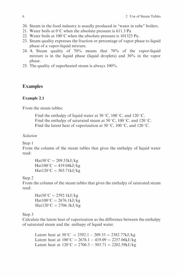
20. Steam in the food industry is usually produced in ‘‘water in tube’’ boilers.21. Water boils at 08C when the absolute pressure is 611.3 Pa22. Water boils at 1008C when the absolute pressure is 101325 Pa.23. Steam quality expresses the fraction or percentage of vapor phase to liquid
phase of a vapor-liquid mixture.24. A Steam quality of 70% means that 70% of the vapor-liquid
mixture is in the liquid phase (liquid droplets) and 30% in the vaporphase.
25. The quality of superheated steam is always 100%.
Examples
Example 2.1
From the steam tables:
Find the enthalpy of liquid water at 50 8C, 100 8C, and 120 8C.Find the enthalpy of saturated steam at 50 8C, 100 8C, and 120 8C.Find the latent heat of vaporization at 50 8C, 100 8C, and 120 8C.
Solution
Step 1From the column of the steam tables that gives the enthalpy of liquid waterread:
Hat508C ¼ 209:33kJ=kgHat1008C ¼ 419:04kJ=kgHat1208C ¼ 503:71kJ=kg
Step 2From the column of the steam tables that gives the enthalpy of saturated steamread:
Hat508C ¼ 2592:1kJ=kgHat1008C ¼ 2676:1kJ=kgHat1208C ¼ 2706:3kJ=kg
Step 3Calculate the latent heat of vaporization as the difference between the enthalpyof saturated steam and the enthapy of liquid water.
Latent heat at 508C ¼ 2592:1� 209:33 ¼ 2382:77kJ=kgLatent heat at 1008C ¼ 2676:1� 419:09 ¼ 2257:06kJ=kgLatent heat at 1208C ¼ 2706:3� 503:71 ¼ 2202:59kJ=kg
6 2 Use of Steam Tables

Example 2.2
Find the enthalpy of superheated steam with pressure 150 kPa and temperature150 8C.
Solution
Step 1Find the enthalpy from the steam tables for superheated steam:
H steam ¼ 2772:6kJ=kg
Step 2Alternatively find an approximate value from:
H steam ¼ H saturated þ cp vapor T� Tsaturationð Þ ¼ 2693:4þ 1:909� 150� 111:3ð Þ¼ 2767:3 kJ=kg
Example 2.3
If the enthalpy of saturated steam at 50 8C and 55 8C is 2592.1 kJ/kg and 2600.9kJ/kg respectively, find the enthalpy at 53 8C.
Solution
Find the enthalpy at 53 8C by interpolation between the values for 50 8C and558C given in steam tables, assuming that the enthalpy in this range changeslinearly:
H ¼ 2592:1þ 53� 50
55� 502600:9� 2592:1ð Þ ¼ 2597:4 kJ=kg
Exercises
Exercise 2.1
Find the boiling temperature of a juice that is boiling at an absolute pressure of31.19 Pa. Assume that the boiling point elevation is negligible.
Solution
From the steam tables, find the saturation temperature at water vapor pressureequal to 31.19 kPa as T = ...................8C. Therefore the boiling temperaturewill be .......................
Exercises 7

Exercise 2.2
A food product is heated by saturated steam at 100 8C. If the condensate exits at90 8C, how much heat is given off per kg steam?
Solution
Step 1Find the the enthalpy of steam and condensate from steam tables:
H steam¼::::::::::::::::::::::::::::::::::kJ=kg;
H condensate¼::::::::::::::::::::::::::::::::::kJ=kg:
Step 2Calculate the heat given off:
H ¼ :::::::::::::::::::::::::� ::::::::::::::::::::::::::: ¼ 2299:2 kJ=kg
Exercise 2.3
Find the enthalpy of steam at 169.06 kPa pressure if its quality is 90%.
Solution
Step 1Find the enthalpy of saturated steam at 169.06 kPa from the steam tables:
H steam ¼ :::::::::::::::::::::::::::::::::::::::::::::::::::
Step 2Find the enthalpy of liquid water at the corresponding temperature from thesteam tables:
H liquid ¼ ::::::::::::::::::::::::::::::::::::::::::::::::::::::::
Step 3Calculate the enthalpy of the given steam:
H ¼ xsHs þ 1� xsð ÞHL ¼¼ ::::::::::::::::::� ::::::::::::::::::::þ ::::::::::::::::::� ::::::::::::::::: ¼ 2477:3 kJ=kg
Exercise 2.4
Find the vapor pressure of water at 72 8C if the vapor pressure at 70 8C and
75 8C is 31.19 kPa and 38.58 kPa respectively.(Hint: Use linear interpolation.)
8 2 Use of Steam Tables
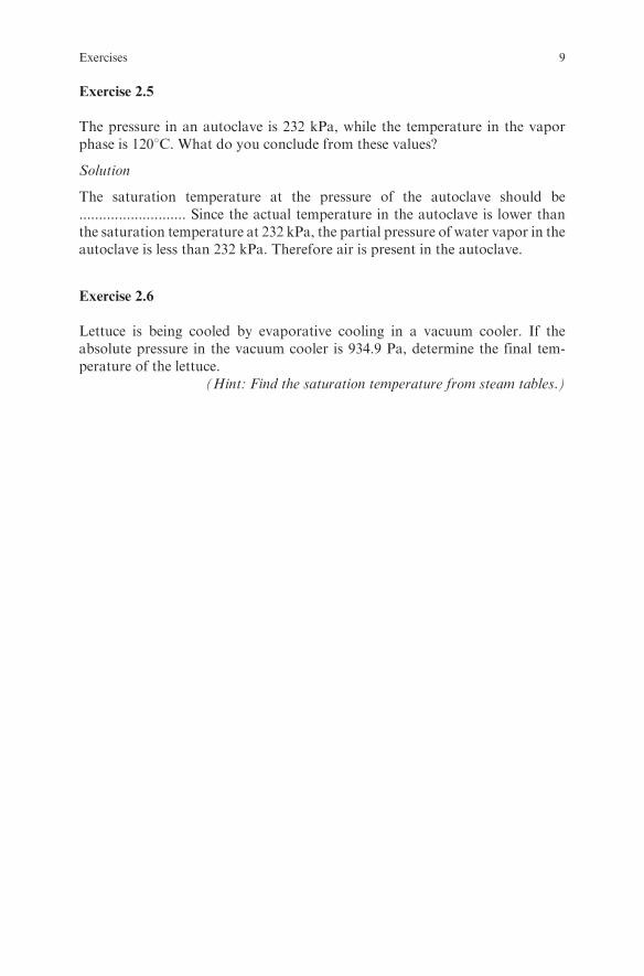
Exercise 2.5
The pressure in an autoclave is 232 kPa, while the temperature in the vaporphase is 1208C. What do you conclude from these values?
Solution
The saturation temperature at the pressure of the autoclave should be........................... Since the actual temperature in the autoclave is lower thanthe saturation temperature at 232 kPa, the partial pressure of water vapor in theautoclave is less than 232 kPa. Therefore air is present in the autoclave.
Exercise 2.6
Lettuce is being cooled by evaporative cooling in a vacuum cooler. If theabsolute pressure in the vacuum cooler is 934.9 Pa, determine the final tem-perature of the lettuce.
(Hint: Find the saturation temperature from steam tables.)
Exercises 9
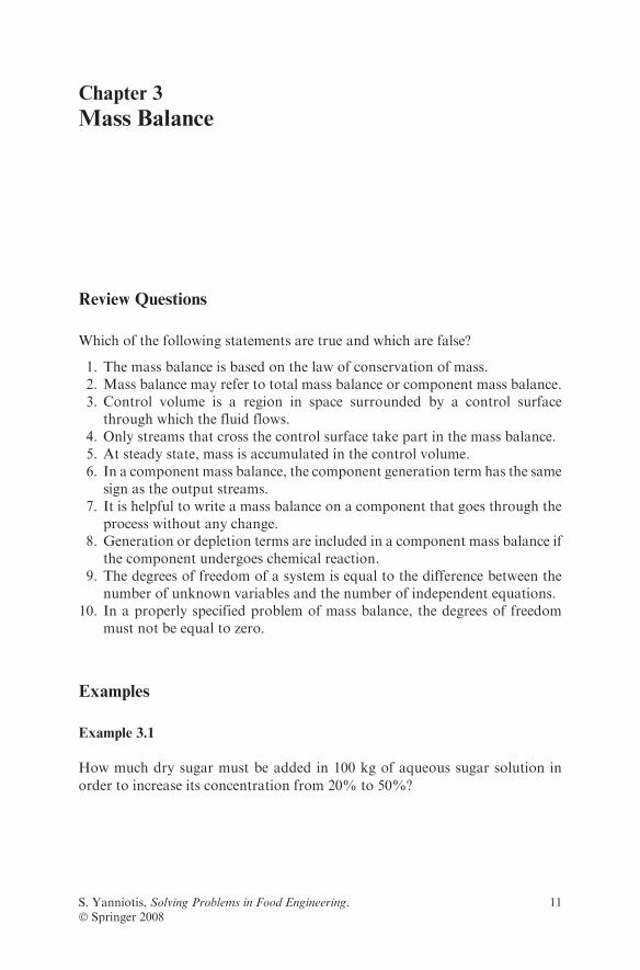
Chapter 3
Mass Balance
Review Questions
Which of the following statements are true and which are false?
1. The mass balance is based on the law of conservation of mass.2. Mass balance may refer to total mass balance or component mass balance.3. Control volume is a region in space surrounded by a control surface
through which the fluid flows.4. Only streams that cross the control surface take part in the mass balance.5. At steady state, mass is accumulated in the control volume.6. In a component mass balance, the component generation term has the same
sign as the output streams.7. It is helpful to write a mass balance on a component that goes through the
process without any change.8. Generation or depletion terms are included in a component mass balance if
the component undergoes chemical reaction.9. The degrees of freedom of a system is equal to the difference between the
number of unknown variables and the number of independent equations.10. In a properly specified problem of mass balance, the degrees of freedom
must not be equal to zero.
Examples
Example 3.1
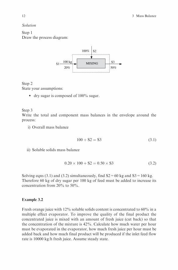
How much dry sugar must be added in 100 kg of aqueous sugar solution in
order to increase its concentration from 20% to 50%?
S. Yanniotis, Solving Problems in Food Engineering.� Springer 2008
11
Solution
Step 1Draw the process diagram:
S1
S2
S3
20%
100%
50%MIXING100 kg
Step 2State your assumptions:
l dry sugar is composed of 100% sugar.
Step 3Write the total and component mass balances in the envelope around theprocess:
i) Overall mass balance
100þ S2 ¼ S3 (3:1)
ii) Soluble solids mass balance
0:20� 100þ S2 ¼ 0:50� S3 (3:2)
Solving eqns (3.1) and (3.2) simultaneously, find S2=60 kg and S3=160 kg.Therefore 60 kg of dry sugar per 100 kg of feed must be added to increase itsconcentration from 20% to 50%.
Example 3.2
Fresh orange juice with 12% soluble solids content is concentrated to 60% in amultiple effect evaporator. To improve the quality of the final product the
concentrated juice is mixed with an amount of fresh juice (cut back) so thatthe concentration of the mixture is 42%. Calculate how much water per hourmust be evaporated in the evaporator, how much fresh juice per hour must beadded back and how much final product will be produced if the inlet feed flowrate is 10000 kg/h fresh juice. Assume steady state.
12 3 Mass Balance

Solution
Step 1Draw the process diagram:
10000 kg/h X Y
F
60%
12%
42%12%
W
MIXINGEVAPORATION
III
Step 2Write the total and component mass balances in envelopes I and II:
i) Overall mass balance in envelope I
10000 ¼WþX (3:3)
ii) Soluble solids mass balance in envelope I
0:12� 10000 ¼ 0:60�X (3:4)
iii) Overall mass balance in envelope II
Xþ F ¼ Y (3:5)
iv) Soluble solids mass balance in envelope II
0:60�Xþ 0:12� F ¼ 0:42�Y (3:6)
From eqn (3.4) find X=2000 kg/h. Substituting X in eqn (3.3) and find
W=8000 kg/h. Solve eqns (iii) and (iv) simultaneously and Substitute X in
eqn (3.3) and find=1200 kg/h and Y=3200 kg/h.Therefore 8000 kg/h of water will be evaporated, 1200 kg/h of fresh juice will be
added back and 3200 kg/h of concentrated orange juice with 42% soluble solids
will be produced.
Exercise 3.3
1000 kg/h of a fruit juice with 10% solids is freeze-concentrated to 40%
solids. The dilute juice is fed to a freezer where the ice crystals are formed
Examples 13

and then the slush is separated in a centrifugal separator into ice crystalsand concentrated juice. An amount of 500 kg/h of liquid is recycled from theseparator to the freezer. Calculate the amount of ice that is removed inthe separator and the amount of concentrated juice produced. Assumesteady state.
Solution
Step 1Draw the process diagram:
1000 kg/h
Ice
J
40%10%SEPARATIONFREEZING
I
Step 2Write the total and component mass balances in the envelope around theprocess:
i) Overall mass balance
1000 ¼ Iþ J (3:7)
ii) Soluble solids mass balance
0:10� 1000 ¼ 0:40� J (3:8)
From eqn (3.8) find J=250 kg/h and then from eqn (3.7) find I=750 kg/h.
Comment: Notice that the recycle stream does not affect the result. Only thestreams that cut the envelope take part in the mass balance.
Exercises
Exercise 3.1
Howmany kg/h of sugar syrup with 10% sugar must be fed to an evaporator toproduce 10000 kg/h of sugar syrup with 65% sugar?
14 3 Mass Balance

Solution
Step 1Draw the process diagram:
10000 kg/hX65%10%
W
EVAPORATION
Step 2State your assumptions:
..........................................................................................................................
Step 3Write the mass balance for sugar on the envelope around the process:
0:10�X ¼::::::::::::::::::::::::::::::::::::::::::::::::::::::::::::::
Step 4Solve the above equation and find
X=............................................................. .. kg/h
Exercise 3.2
How much water must be added to 200 kg of concentrated orange juice with
65% solids to produce orange juice with 12% solids
Solution
Step 1Draw the process diagram:
200 kg
W
J
65% 12%MIXING
Water
Exercises 15

Step 2Write the mass balance for solids on the envelope around the process:
.......................................¼.......................................
Solve the above equation and find J=........................................ kg
Exercise 3.3
Milk with 3.8% fat and 8.1% fat-free solids (FFS) is used for the productionof canned concentrated milk. The process includes separation of the cream ina centrifuge and concentration of the partially defatted milk in an evaporator.If the cream that is produced in the centrifuge contains 55% water, 40% fat,and 5% fat-free solids, calculate how much milk is necessary in order toproduce a can of concentrated milk that contains 410 g milk with 7.8% fatand 18.1% fat-free solids. How much cream and how much water must beremoved in the centrifuge and the evaporator respectively? Assume steadystate.
Solution
Step 1Draw the process diagram:
X410 g
FFS 8.1%EVAPORATIONCENTRIFUGATION
Fat 3.8%FFS 18.1%Fat 7.8%
WaterCream
5% FFS
C W55% W40% F
Step 2Write the total and component mass balances in the envelope around theprocess:
i) Overall mass balance
:::::::::::::::::::::: ¼ ::::::::::::::::::þWþ :::::::::::::::::::::: (3:9)
ii) Fat-free solids mass balance
:::::::::::::::::::::::::::::: ¼ 0:05� Cþ :::::::::::::::::::::::::::: (3:10)
16 3 Mass Balance

iii) Fat mass balance
0:038�X ¼:::::::::::::::::::::::::::::::::þ ::::::::::::::::::::::::::::::::: (3:11)
Solve eqns (3.9), (3.10) and (3.11) simultaneously and find X=.................. g,C= ............................... g and W=............................... g.
Exercise 3.4
According to some indications, crystallization of honey is avoided if the ratio ofglucose to water is equal to 1.70. Given the composition of two honeys, find theproportions in which they have to be mixed so that the ratio of glucose to waterin the blend is 1.7. What will be the composition of the blend?
Honey H1: glucose 35%, fructose 33%, sucrose 6%, water 16%.Honey H2: glucose 27%, fructose 37%, sucrose 7%, water 19%.
Solution
Step 1Draw the process diagram:
Glucose 27%Fructose 37%Sucrose 7%Water 19%
MIXING
H2
Glucose 35%Fructose 33%Sucrose 6%Water 16%
H1 Hb
Step 2Select 1000 kg of blend as a basis for calculation (Hb=1000 kg).
Step 3Write the total and componentmass balances in the envelope around the process:
i) Overall mass balance
::::::::::::::::::::::::::þ :::::::::::::::::::::::::::: ¼ ::::::::::::::::::::::::::::::::: (3:12)
ii) Glucose mass balance
::::::::::::::::::::::::::::þ :::::::::::::::::::::::::::: ¼ :::::::::::::::::::::::::::: (3:13)
Exercises 17
iii) Fructose mass balance
::::::::::::::::::::::::::::þ :::::::::::::::::::::::::::: ¼ :::::::::::::::::::::::::::: (3:14)
iv) Sucrose mass balance
::::::::::::::::::::::::::::þ :::::::::::::::::::::::::::: ¼ :::::::::::::::::::::::::::: (3:15)
v) Water mass balance
::::::::::::::::::::::::::::þ :::::::::::::::::::::::::::: ¼ :::::::::::::::::::::::::::: (3:16)
vi) Ratio of glucose to water in the blend
G=W ¼ 1:70 (3:17)
Solve eqns (3.12) to (3.17) simultaneously and find:
H1 ¼ .............................................................. kgH2 ¼ .............................................................. kgH1/H2 ¼ ............................................................
The composition of the blend will be:
glucose ¼ ..........................................................fructose ¼ .........................................................sucrose ¼ ..........................................................water ¼ .............................................................
Exercise 3.5
How much glucose syrup with 20% concentration has to be mixed with 100 kg
glucose syrup with 40% concentration so that the mixture will have 36%
glucose?
Exercise 3.6
Howmany kg of saturated sugar solution at 70 8C can be prepared from 100 kg
of sucrose? If the solution is cooled from 70 8C to 20 8C, how many kg of sugar
will be crystallized? Assume that the solubility of sucrose as a function oftemperature (in 8C) is given by the equation: % sucrose ¼ 63.2 þ 0.146T þ0.0006T2.
18 3 Mass Balance
Exercise 3.7
Find the ratio of milk with 3.8% fat to milk with 0.5% fat that have to be mixedin order to produce a blend with 3.5% fat.
Exercise 3.8
For the production of marmalade, the fruits are mixed with sugar andpectin and the mixture is boiled to about 65% solids concentration. Find theamount of fruits, sugar, and pectin that must be used for the production of 1000kg marmalade, if the solids content of the fruits is 10%, the ratio of sugar tofruit in the recipe is 56:44, and the ratio of sugar to pectin is 100.
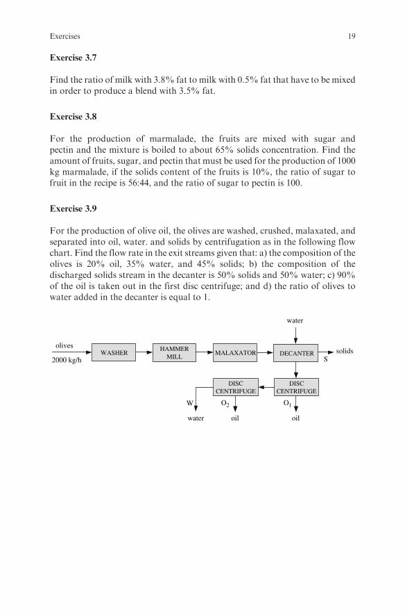
Exercise 3.9
For the production of olive oil, the olives are washed, crushed, malaxated, andseparated into oil, water. and solids by centrifugation as in the following flowchart. Find the flow rate in the exit streams given that: a) the composition of theolives is 20% oil, 35% water, and 45% solids; b) the composition of thedischarged solids stream in the decanter is 50% solids and 50% water; c) 90%of the oil is taken out in the first disc centrifuge; and d) the ratio of olives towater added in the decanter is equal to 1.
2000 kg/h
olivesWASHER
HAMMERMILL
MALAXATOR DECANTER
DISCCENTRIFUGE
DISCCENTRIFUGE
water oil oil
solids
water
S
O2W O1
Exercises 19

Chapter 4
Energy Balance
Theory
The overall energy balance equation for a system with one inlet (point 1) andone outlet (point 2) is:
H1 þvml
2
2�þ z1g
� �_m1 � H2 þ
vm22
2�þ z2g
� �_m2 þ q�Ws ¼
d mEð Þdt
The overall energy balance equation for a system at steady state with more thantwo streams can be written as:
XHþ v2m
2�þ zg
� �_m
� �¼ q�Ws
where H = enthalpy, J/kgvm = average velocity, m/s� = correction coefficient (for a circular pipe �= 1/2 for
laminar flow, � � 1 for turbulent flow)z = relative height from a reference plane, mm = mass of the system, kg_m = mass flow rate, kg/sq = heat transferred across the boundary to or from the system
(positive if heat flows to the system), WWs= shaft work done by or to the system (positive if work is done
by the system), WE = total energy per unit mass of fluid in the system, J/kgt = time, s
In most of the cases, the overall energy balance ends up as an enthalpybalance because the terms of kinetic and potential energy are negligible com-pared to the enthalpy term, the system is assumed adiabatic (Q ¼ 0), and thereis no shaft work (Ws ¼ 0). Then:X
_mH ¼ 0
S. Yanniotis, Solving Problems in Food Engineering.� Springer 2008
21

Review Questions
Which of the following statements are true and which are false?
1. The energy in a system can be categorize as internal energy, potentialenergy, and kinetic energy.
2. A fluid stream carries internal energy, potential energy, and kineticenergy.
3. A fluid stream entering or exiting a control volume is doing PV work.4. The internal energy and the PV work of a stream of fluid make up the
enthalpy of the stream.5. Heat and shaft work may be transferred through the control surface to or
from the control volume.6. Heat transferred from the control volume to the surroundings is considered
positive by convention.7. For an adiabatic process, the heat transferred to the system is zero.8. Shaft work supplied to the system is considered positive by convention.9. The shaft work supplied by a pump in a system is considered negative.
10. If energy is not accumulated in or depleted from the system, the system is atsteady state.
Examples
Example 4.1
1000 kg/h ofmilk is heated in a heat exchanger from 458C to 728C.Water is used
as the heating medium. It enters the heat exchanger at 908C and leaves at 758C.Calculate the mass flow rate of the heating medium, if the heat losses to the
environment are equal to 1 kW. The heat capacity of water is given equal to
4.2 kJ/kg8C and that of milk 3.9 kJ/kg8C.
Solution
Step 1Draw the process diagram:
1000 kg/hmilk
q
HEATEXCHANGER
45°C
75°C
72°C
90°C
milk
waterwater
22 4 Energy Balance

Step 2State your assumptions:
l The terms of kinetic and potential energy in the energy balance equationare negligible.
l A pump is not included in the system (Ws ¼ 0).l The heat capacity of the liquid streams does not change significantly
with temperature.l The system is at steady state.
Step 3Write the energy balance equation:
Rate of energy input ¼ _mw in �Hw in þ _mm in �Hm in
Rate of energy output ¼ _mw out �Hw out þ _mm out �Hm out þ q
(with subscript ‘‘w’’ for water and ‘‘m’’ for milk).
At steady state
rate of energy input ¼ rate of energy output
or
_mw in �Hw in þ _mm in �Hm in ¼ _mw out �Hw out þ _mm out �Hm out þ q (4:1)
Step 4Calculate the known terms of eqn (4.1)
i) The enthalpy of the water stream is:
Input: Hw in ¼ cpT ¼ 4:2 � 90 ¼ 378 kJ=kg
Output: Hw out ¼ cpT ¼ 4:2 � 75 ¼ 315 kJ=kg
ii) The enthalpy of the milk stream is:
Input: Hm in ¼ cpT ¼ 3:9 � 45 ¼ 175:5 kJ=kg
Output: Hm out ¼ cpT ¼ 3:9 � 72 ¼ 280:8 kJ=kg
Step 5Substitute the above values in eqn (4.1), taking into account that:
_mw in ¼ _mw out ¼ _mwand _mm in ¼ _mm out
_mw � 378þ 1000� 175:5 ¼ _mw � 315þ 1000� 280:8 þ 1� 3600
Examples 23
Step 6Solve for _mw
_mw ¼ 1728:6 kg=h
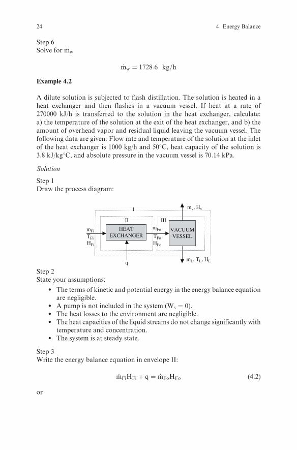
Example 4.2
A dilute solution is subjected to flash distillation. The solution is heated in a
heat exchanger and then flashes in a vacuum vessel. If heat at a rate of
270000 kJ/h is transferred to the solution in the heat exchanger, calculate:
a) the temperature of the solution at the exit of the heat exchanger, and b) the
amount of overhead vapor and residual liquid leaving the vacuum vessel. The
following data are given: Flow rate and temperature of the solution at the inlet
of the heat exchanger is 1000 kg/h and 508C, heat capacity of the solution is
3.8 kJ/kg8C, and absolute pressure in the vacuum vessel is 70.14 kPa.
Solution
Step 1Draw the process diagram:
q
HEATEXCHANGER
II
I
VACUUMVESSEL
mL, TL, HL
III
TFi
mFo
mv, Hv
TFoHFo
mFi
HFi
Step 2State your assumptions:
l The terms of kinetic and potential energy in the energy balance equationare negligible.
l A pump is not included in the system (Ws ¼ 0).l The heat losses to the environment are negligible.l The heat capacities of the liquid streams do not change significantly with
temperature and concentration.l The system is at steady state.
Step 3Write the energy balance equation in envelope II:
_mFiHFi þ q ¼ _mFoHFo (4:2)
or
24 4 Energy Balance

_mFicpFTFi þ q ¼ _mFocpFTFo (4:3)
Substitute known values:
1000� 3:8� 50þ 270000 ¼ 1000� 3:8� TFo (4:4)
Solve for TFo:
TFo ¼ 121 oC
Step 4Write the mass and energy balance equations in envelope I:
i) Overall mass balance:
_mFi ¼ _mV þ _mL (4:5)
ii) Energy balance:
_mFiHFi þ q ¼ _mVHV þ _mLHL (4:6)
or
_mFicpFTFi þ q ¼ _mVHV þ _mLcpLTL (4:7)
Step 5Calculate mv using equations (4.5), (4.6) and (4.7):
i) From eqn (4.5):
_mL ¼ _mFi � _mV (4:8)
ii) Substitute eqn (4.8) in (4.7):
_mFicpFTFi þ q ¼ _mVHV þ _mFi� _mVð ÞcpLTL (4:9)
iii) Find the saturation temperature and the enthalpy of saturated vapor at70.14 kPa from the steam tables:
TL=908C
V=2660 kJ/kg
iv) Substitute numerical values in eqn (4.9):
1000� 3:8� 50þ 270000 ¼ _mV � 2660þ 1000� _mVð Þ � 3:8� 90
Examples 25

v) Solve for _mV
_mv ¼ 50:9 kg=h
Step 6Alternatively, an energy balance in envelope III can be used instead ofenvelope I:
i) Write the energy balance equation:
_mFocpFTFo ¼ _mVHV þ _mLcpLTL (4:10)
ii) Combine eqns (4.5) and (4.10) and substitute numerical values:
1000� 3:8� 121 ¼ _mV � 2660þ 1000� _mVð Þ � 3:8� 90
iii) Solve for _mV
_mv ¼ 50:9 kg=h
Exercises
Exercise 4.1
Howmuch saturated steam with 120.8 kPa pressure is required to heat 1000 g/h
of juice from 58C to 958C? Assume that the heat capacity of the juice is 4 kJ/
kg8C.
Solution
Step 1Draw the process diagram:
HEATEXCHANGER
5°C 95°Cjuice
condensate120.8kPa
steam120.8kPa
mji = 1000 kg/hjuice
mjo
ms ms
26 4 Energy Balance
Step 2Write the energy balance equation:
_mjiHji þ _msHs ¼ ::::::::::::::::::::::::::::::: þ ::::::::::::::::::::::::::::::::
or
_mjicpjTji þ _msHs ¼ :::::::::::::::::::::::::::::::þ ::::::::::::::::::::::::::::::::
Step 3Substitute numerical values in the above equation.(Find the enthalpy of saturated steam and water [condensate] from steam
tables):
::::::::::::::::::::::::::::þ ::::::::::::::::::::::::::: ¼ :::::::::::::::::::::::::þ ::::::::::::::::::::::::
Step 4Solve for _ms
_ms ¼ ::::::::::::::::::::::::::::::::::::::kg=h
Exercise 4.2
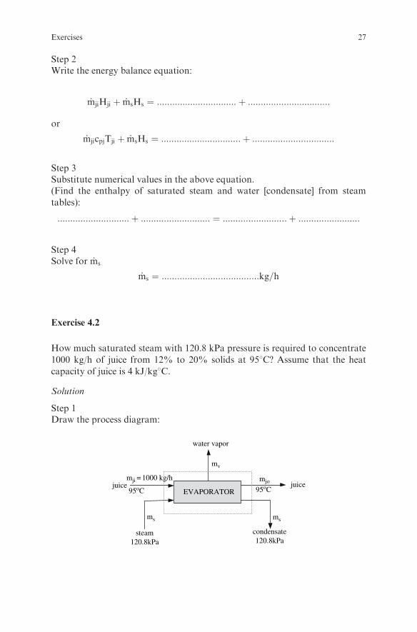
How much saturated steam with 120.8 kPa pressure is required to concentrate
1000 kg/h of juice from 12% to 20% solids at 958C? Assume that the heat
capacity of juice is 4 kJ/kg8C.
Solution
Step 1Draw the process diagram:
EVAPORATOR
water vapor
95oC 95oCjuice
condensate120.8kPa
steam120.8kPa
mji = 1000 kg/hjuice
mjo
mv
ms ms
Exercises 27
Step 2Write the overall mass balance equation on the juice side:
1000 ¼ _mV þ _mjo
Step 3Write the solids mass balance equation:
0:12� 1000 ¼ ::::::::::::::: � _mjo
Solve for _mjo and _mV
_mjo ¼ :::::::::::::::::::::::::::::::::::::::::::::::::::::::::::::::::::::::::::kg=h
_mV ¼ :::::::::::::::::::::::::::::::::::::::::::::::::::::::::::::::::::::::::::kg=h
Step 4
i) Write the enthalpy balance equation:
_mjicpjTji þ _msHs ¼ ::::::::::::::::::::::: þ ::::::::::::::::::::::::: ¼ :::::::::::::::::::
ii) From steam tables, find the enthalpy of water vapor at 958C, of saturatedsteam at 120.8 kPa, and of water (condensate) at 120.8 kPa.
iii) Substitute numerical values in the above equation:
::::::::::::::::::þ ::::::::::::::::: ¼ :::::::::::::::::: þ :::::::::::::::::þ :::::::::::::::::
iv) Solve for _ms
_ms ¼ ::::::::::::::::::::::::::::::::::::::::kg=h
Exercise 4.3
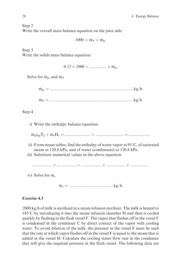
2000 kg/h of milk is sterilized in a steam infusion sterilizer. Themilk is heated to
1458C by introducing it into the steam infusion chamber H and then is cooledquickly by flashing in the flash vessel F. The vapor that flashes off in the vessel Fis condensed in the condenser C by direct contact of the vapor with coolingwater. To avoid dilution of the milk, the pressure in the vessel F must be such
that the rate at which vapor flashes off in the vessel F is equal to the steam that isadded in the vessel H. Calculate the cooling water flow rate in the condenserthat will give the required pressure in the flash vessel. The following data are
28 4 Energy Balance
given: The temperature of the milk at the inlet of H is 408C, the temperature of
the cooling water at the inlet of the condenser is 208C, the steam introduced into
the chamber H is saturated at 475.8 kPa pressure, and the heat capacity of the
milk is 3.8 kJ/kg8C at the inlet of the infusion chamber and 4 kJ/kg8C at the exit
of the infusion chamber.
Solution
Step 1Draw the process diagram:
III III
milk
steam
H
milk
vapor
F
coolingwater
C
mmi, Hmi
mv, Hv
mwi, Hwi
mwo, Hwommo, Hmo
mms, Hms
ms, Hs
Step 2State your assumptions:
l The terms of kinetic and potential energy in the energy balance equationare negligible.
l A pump is not included in the system (Ws ¼ 0).l The heat losses to the environment are negligible.l The water vapor pressure of the milk is equal to that of water at the same
temperature.l The water vapor pressure in the condenser is equal to the water vapor
pressure in the flash vessel.l The system is at steady state.
Step 3Write the mass and energy balance equations in envelope I:
i) Energy balance in envelope I:
_mmiHmi þ _msHs ¼ _mmsHms
ii) Overall mass balance in envelope I:
::::::::::::::::::::::::::::::::þ ::::::::::::::::::::::::::: ¼ :::::::::::::::::::::::::::::
Exercises 29

iii) Substitute numerical values and combine the last two equations:
::::::::::::::::::::::::::::::::::þ 2746:5 _ms ¼ :::::::::::::::::::::::::::::::::
iv) Solve for _ms
_ms ¼ ::::::::::::::::::::::::::::::::::::::::::::::::kg=h
Step 4
i) Write the energy balance in envelope II:
::::::::::::::::::::::::: ¼ :::::::::::::::::::::::::::þ ::::::::::::::::::::::::::::
ii) Substitute values taking into account that _ms ¼ _mv, in order to avoiddilution of the milk:
::::::::::::::::::::::::::::::::: ¼ ::::::::::::::::::::::::::::::þ ::::::::::::::::::::::::::::::::
or
1389158� 7600� T ¼ 395:1�HV
iii) Solve the last equation by trial and error to find the value of T that willgive a value of HV in agreement with steam tables.
T = . . .. . .. . .. . .. . .. . .. . ...8C.
Step 5Write the overall mass balance and energy balance in envelope III:
i) Overall mass balance:
::::::::::::::::::::::::::::þ ::::::::::::::::::::::::::: ¼ :::::::::::::::::::::::::::::::
ii) Energy balance:
::::::::::::::::::::::::::::þ ::::::::::::::::::::::::::: ¼ :::::::::::::::::::::::::::::::
iii) Substitute numerical values in the last equation and solve for mwi.
The temperature of the water at the exit of the condenser must be equal to
::::::::::::::::::::�C, because the water vapor pressure in the condenser was
assumed equal to that in the flash vessel F.
_mwi ¼ :::::::::::::::::::::::::::::::::::::::kg=h
30 4 Energy Balance
Exercise 4.4
Find the amount of saturated steam at 270.1 kPa required to heat 100 kg of cansfrom 508C to 1218C, if the heat capacity of the cans is 3.5 kJ/kg8C.
Exercise 4.5
One ice cube at �108C weighing 30g is added to a glass containing 200ml ofwater at 208C. Calculate the final water temperature when the ice cube meltscompletely. Assume that 3 kJ of heat are transferred from the glass to the waterduring the melting of the ice? Use the following values: the latent heat of fusionof the ice is 334 kJ/kg, the heat capacity of the ice is 1.93 kJ/kg8C, and the heatcapacity of the water is 4.18 kJ/kg8C.
Exercise 4.6
For quick preparation of a cup of hot chocolate in a cafeteria, cocoa powderand sugar are added in a cup of water and the solution is heated by direct steaminjection. If the initial temperature of all the ingredients is 158C, the finaltemperature is 958C, the mass of the solution is 150g initially, and the heatcapacity of the solution is 3.8 kJ/kg8C, calculate how much saturated steam at1108C will be used. State your assumptions.
Exercise 4.7
Calculate the maximum temperature to which a liquid food can be preheated bydirect steam injection if the initial temperature and the initial solids concentra-tion of the food are 208C and 33% respectively, and the final solids concentra-tion must not be less than 30%. Howmuch saturated steam at 121 kPa pressurewill be used? Assume that the heat capacity of the food is 3.0 kJ/kg8C initiallyand 3.1 kJ/kg8C after the steam injection.
Exercises 31
Chapter 5
Fluid Flow
Review Questions
Which of the following statements are true and which are false?
1. TheReynolds number represents the ratio of the inertia forces to viscous forces.2. If the Reynolds number in a straight circular pipe is less than 2100, the flow
is laminar.3. The velocity at which the flow changes from laminar to turbulent is called
critical velocity.4. The Reynolds number in non-Newtonian fluids is called the Generalized
Reynolds number5. The velocity profile of Newtonian fluids in laminar flow inside a circular
pipe is parabolic.6. The velocity profile of Newtonian fluids in laminar flow is flatter than in
turbulent flow.7. Themaximum velocity of Newtonian fluids in laminar flow inside a circular
pipe is twice the bulk average velocity.8. The average velocity of Newtonian fluids in turbulent flow inside a circular
pipe is around 80% of the maximum velocity.9. The maximum velocity of pseudoplastic fluids in laminar flow inside a
circular pipe is more than twice the bulk average velocity.10. The Hagen-Poiseuille equation gives the pressure drop as a function of the
average velocity for turbulent flow in a horizontal pipe.11. The pressure drop in laminar flow is proportional to the volumetric flow rate.12. The pressure drop in turbulent flow is approximately proportional to the
7/4 power of the volumetric flow rate.13. In a fluid flowing in contact with a solid surface, the region close to the solid
surface where the fluid velocity is affected by the solid surface is calledboundary layer.
14. The velocity gradients and the shear stresses are larger in the region outsidethe boundary layer than in the boundary layer.
15. Boundary layer thickness is defined as the distance from the solid surfacewhere the velocity reaches 99% of the free stream velocity.
S. Yanniotis, Solving Problems in Food Engineering.� Springer 2008
33
16. The viscosity of a liquid can be calculated if the pressure drop of the liquidflowing in a horizontal pipe in laminar flow is known.
17. The viscosity of non-Newtonian liquids is independent of the shear rate.18. The flow behavior index in pseudoplastic liquids is less than one.19. In liquids that follow the power-law equation, the relationship between
average velocity and maximum velocity is independent of the flow behaviorindex.
20. The apparent viscosity of a pseudoplastic liquid flowing in a pipe decreasesas the flow rate increases.
Examples
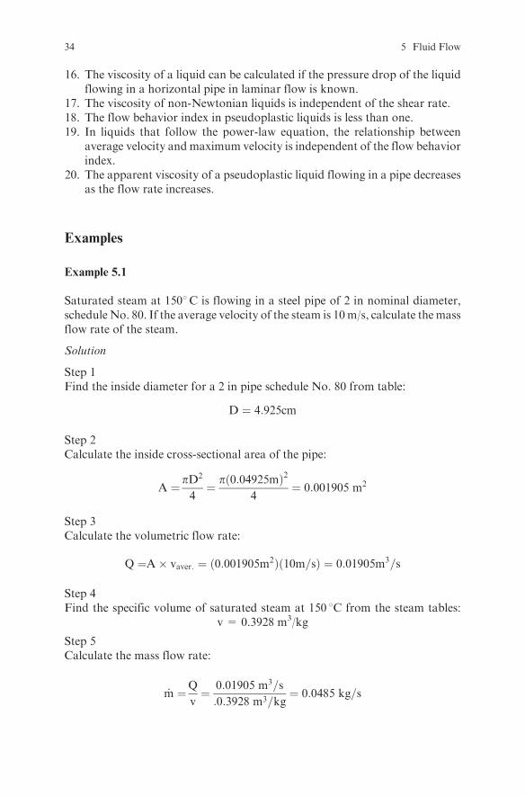
Example 5.1
Saturated steam at 1508C is flowing in a steel pipe of 2 in nominal diameter,schedule No. 80. If the average velocity of the steam is 10m/s, calculate themassflow rate of the steam.
Solution
Step 1Find the inside diameter for a 2 in pipe schedule No. 80 from table:
D ¼ 4:925cm
Step 2Calculate the inside cross-sectional area of the pipe:
A ¼ pD2
4¼ pð0:04925mÞ2
4¼ 0:001905 m2
Step 3Calculate the volumetric flow rate:
Q ¼A� vaver: ¼ ð0:001905m2Þð10m=sÞ ¼ 0:01905m3=s
Step 4Find the specific volume of saturated steam at 150 8C from the steam tables:
v = 0.3928 m3/kg
Step 5Calculate the mass flow rate:
_m ¼Q
v¼ 0:01905 m3=s
:0:3928 m3=kg¼ 0:0485 kg=s
34 5 Fluid Flow

Example 5.2
A 50% sucrose solution at 20 8C is flowing in a pipe with 0.0475 m insidediameter and 10 m length at a rate of 3 m3/h. Find: a) the mean velocity, b) themaximum velocity, and c) the pressure drop of the sucrose solution. Theviscosity and the density of the sucrose solution at 20 8C are 15.43 cp and1232 kg/m3respectively.
Solution
Step 1Calculate the cross-section area of the pipe:
A ¼ pD2
4¼ pð0:0475mÞ2
4¼ 1:77� 10�3m2
Step 2Calculate the mean velocity of the liquid:
vm ¼Q
A¼ 8:33� 10�4m3=s
1:77� 10�3m2¼ 0:471 m=s
Step 3Calculate the Reynolds number:
Re ¼ Dvp
m¼ ð0:0475mÞð0:471m=sð1232kg=m
3Þ15:43� 10�3kg=ms
¼ 1786
Since Re<2100, the flow is laminar and
vmax ¼ 2vm ¼ 2� 0:471m=s ¼ 0:942m=s
Step 4Calculate the pressure drop using the Hagen-Poiseuille equation:
�P ¼ 32vm�L
D2¼ 32ð0:471m=sÞð0:01543PasÞð10mÞ
ð0:0475mÞ2¼ 1030:Pa
Exercises
Exercise 5.1
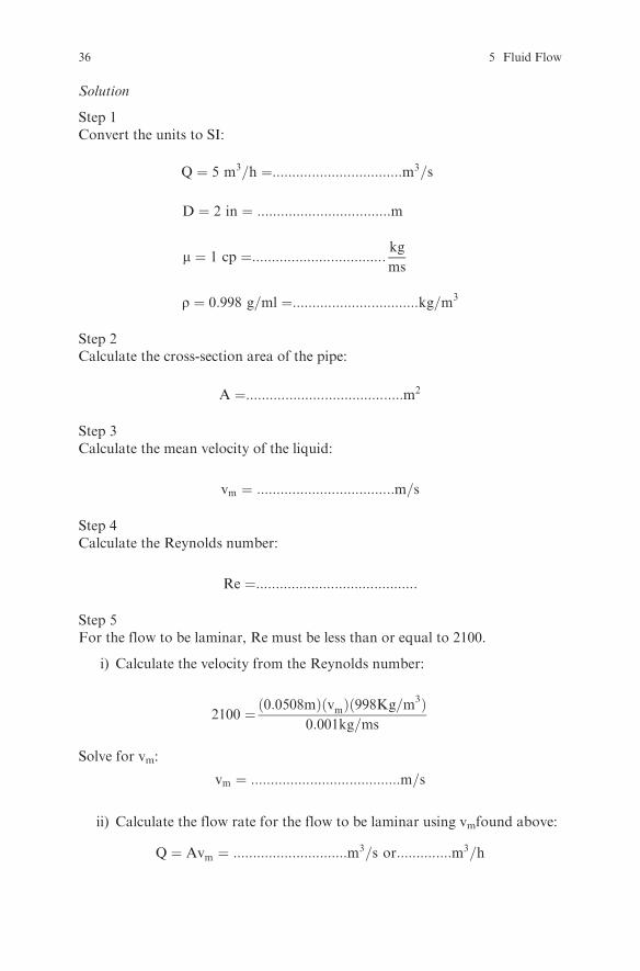
Calculate the Reynolds number for water flowing at 5 m3/h in a tube with 2 ininside diameter if the viscosity and density of water are 1 cp and 0.998 g/mlrespectively. At what flow rate does the flow becomes laminar?
Exercises 35
Solution
Step 1Convert the units to SI:
Q ¼ 5 m3=h ¼:::::::::::::::::::::::::::::::::m3=s
D ¼ 2 in ¼ ::::::::::::::::::::::::::::::::::m
m ¼ 1 cp ¼:::::::::::::::::::::::::::::::::: kgms
r ¼ 0:998 g=ml ¼::::::::::::::::::::::::::::::::kg=m3
Step 2Calculate the cross-section area of the pipe:
A ¼::::::::::::::::::::::::::::::::::::::::m2
Step 3Calculate the mean velocity of the liquid:
vm ¼ :::::::::::::::::::::::::::::::::::m=s
Step 4Calculate the Reynolds number:
Re ¼:::::::::::::::::::::::::::::::::::::::::
Step 5For the flow to be laminar, Re must be less than or equal to 2100.
i) Calculate the velocity from the Reynolds number:
2100 ¼ð0:0508mÞðvmÞð998Kg=m3Þ0:001kg=ms
Solve for vm:
vm ¼ ::::::::::::::::::::::::::::::::::::::m=s
ii) Calculate the flow rate for the flow to be laminar using vmfound above:
Q ¼ Avm ¼ :::::::::::::::::::::::::::::m3=s or::::::::::::::m3=h
36 5 Fluid Flow
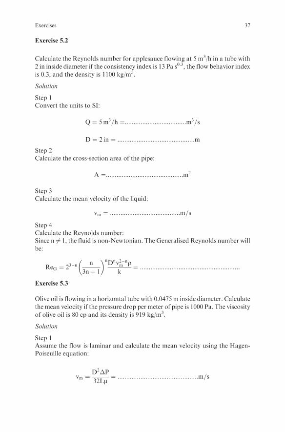
Exercise 5.2
Calculate the Reynolds number for applesauce flowing at 5 m3/h in a tube with2 in inside diameter if the consistency index is 13 Pa s0.3, the flow behavior index
is 0.3, and the density is 1100 kg/m3.
Solution
Step 1Convert the units to SI:
Q ¼ 5m3=h ¼:::::::::::::::::::::::::::::::::::m3=s
D ¼ 2 in ¼ ::::::::::::::::::::::::::::::::::::::::::::mStep 2Calculate the cross-section area of the pipe:
A ¼::::::::::::::::::::::::::::::::::::::::::::m2
Step 3Calculate the mean velocity of the liquid:
vm ¼ ::::::::::::::::::::::::::::::::::::::::m=s
Step 4Calculate the Reynolds number:Since n 6¼ 1, the fluid is non-Newtonian. The Generalised Reynolds number will
be:
ReG ¼ 23�nn
3nþ 1
� �nDnv2�nm r
k¼ :::::::::::::::::::::::::::::::::::::::::::::::::::::::::
Exercise 5.3
Olive oil is flowing in a horizontal tube with 0.0475m inside diameter. Calculate
the mean velocity if the pressure drop per meter of pipe is 1000 Pa. The viscosity
of olive oil is 80 cp and its density is 919 kg/m3.
Solution
Step 1Assume the flow is laminar and calculate the mean velocity using the Hagen-Poiseuille equation:
vm ¼D2�P
32Lm¼ ::::::::::::::::::::::::::::::::::::::::::::::m=s
Exercises 37

Step 2Verify that the flow is laminar:
Re ¼::::::::::::::::::::::::::::::::::::::::::::::::::::::::::::::
Exercise 5.4
Honey at 1 liter/min is flowing in a capillary-tube viscometer 2cm in diameter
and 50 cm long. If the pressure drop is 40 kPa, determine its viscosity.
SolutionThe viscosity can be calculated using the Hagen-Poiseuille equation.
Step 1Find the mean velocity:
vm ¼Q
::::::¼ :::::::::::::::::::::::m=s
Step 2Calculate the viscosity:
m ¼D2�P
32Lvm¼ :::::::::::::::::::::::::Pas
Exercise 5.5
Tomato concentrate is in laminar flow in a pipe with 0.0475 m inside diameter
and 10 m length at a rate of 3 m3/h. Find: a) the mean velocity, b) the maximum
velocity, and c) the pressure drop of the tomato concentrate. The consistency
index and the flow behavior index are K= 18.7 Pas0.4 and n= 0.4 respectively.
Compare the pressure drop for the sucrose solution of Example 5.2 with the
pressure drop of tomato concentrate.
Solution
Step 1Calculate the cross-section area of the pipe:
A ¼ pD2
4¼ :::::::::::::::::m2
Step 2Calculate the mean velocity of the liquid:
vm ¼Q
A¼ ::::::::::::::::::::::m=s
38 5 Fluid Flow
Step 3Use the relationship betweenmean andmaximum velocity for a power-law non-Newtonian fluid in laminar flow to calculate vmax:
vmax
vm¼ 3nþ 1
nþ 1
Therefore
vmax ¼ :::::::::::::::::::::::::::::::::::::::::::::::::::::::::::::::::::::m=s
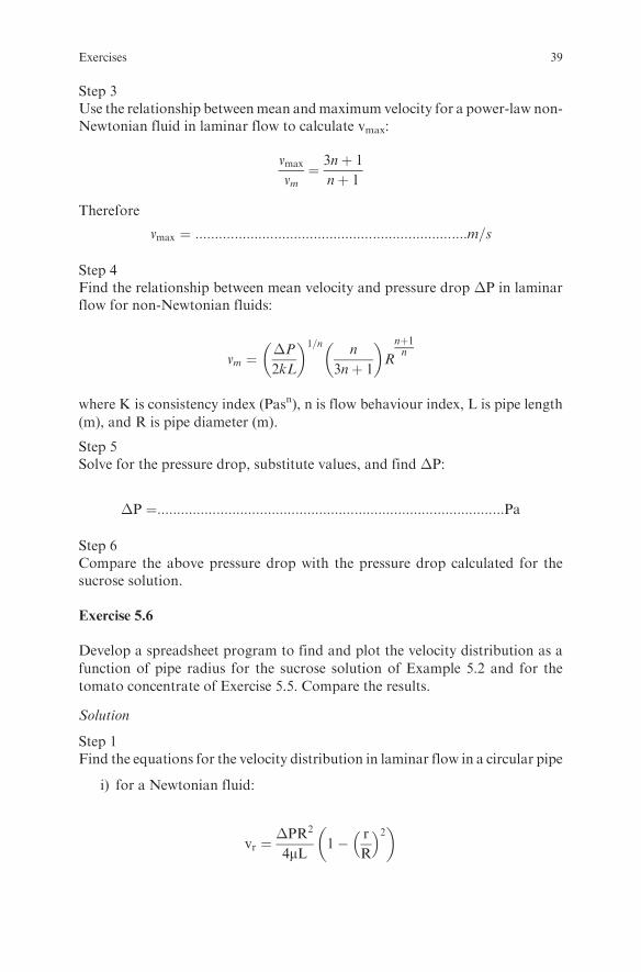
Step 4Find the relationship between mean velocity and pressure drop �P in laminarflow for non-Newtonian fluids:
vm ¼�P
2kL
� �1=nn
3nþ 1
� �R
nþ1n
where K is consistency index (Pasn), n is flow behaviour index, L is pipe length
(m), and R is pipe diameter (m).
Step 5Solve for the pressure drop, substitute values, and find �P:
�P ¼::::::::::::::::::::::::::::::::::::::::::::::::::::::::::::::::::::::::::::::::::::::::Pa
Step 6Compare the above pressure drop with the pressure drop calculated for thesucrose solution.
Exercise 5.6
Develop a spreadsheet program to find and plot the velocity distribution as a
function of pipe radius for the sucrose solution of Example 5.2 and for the
tomato concentrate of Exercise 5.5. Compare the results.
Solution
Step 1Find the equations for the velocity distribution in laminar flow in a circular pipe
i) for a Newtonian fluid:
vr ¼�PR2
4mL1� r
R
� �2� �
Exercises 39

ii) for a non-Newtonian fluid:
vr ¼�P
2KL
� �1=nn
nþ 1
� �Rðnþ1Þ=n 1� r
R
� �ðnþ1Þ=n� �
Step 2Calculate the velocity for various values of radius using the above equations.
Step 3Plot the results.You must end up with the following figure for the sucrose solution and thetomato concentrate:
0.03
0.02
0.01
0.00
0.01
0.02
0.03
Velocity, m/s
Rad
ius,
m
sucrose solution tomato concentrate
0 0.2 0.4 0.6 0.8 1
Step 4Compare the results.
Exercise 5.7
Develop a spreadsheet program to find and plot the velocity distribution as afunction of pipe radius for a dilatant liquid with n = 2 and K = 18.7 Pas2
flowing at a rate of 3 m3/h in a pipe with 0.0475 m inside diameter and 10 mlength.
40 5 Fluid Flow
Chapter 6
Pumps
Theory
The mechanical energy balance equation is used to calculate the required power
for a pump. The mechanical energy balance equation for a systemwith one inlet
(point 1) and one outlet (point 2) is:
vm22 � vm1
2� �
2�þ P2 � P1
rþ z2 � z1ð Þgþ �F ¼ �ws (6:1)
where vm = average velocity, m/sa=kinetic energy correction coefficient (for a circular pipe � ¼ 1=2 for
laminar flow, � � 1 for turbulent flow)P = pressure, Par = density, kg/m3
z = relative height from a reference plane, mg = acceleration of gravity, 9.81 m/s2
�F = friction losses per unit mass of fluid, J/kgws = work supplied by the pump per unit mass of fluid, J/kg
The available Net Positive Suction Head (NPSHa) is:
NPSHa ¼P� pvrg
þ z1 ��Fs
g(6:2)
where P = pressure in the suction tank, Papv = vapor pressure of liquid in the pump, Paz1 =distance of the pump from the liquid level in the suction tank, m (z1
positive if the pump is below the liquid level in the tank, z1 negative ifthe pump is above the liquid level in the tank)
�Fs = friction losses in the suction line, J/kg
S. Yanniotis, Solving Problems in Food Engineering.� Springer 2008
41
Review Questions
Which of the following statements are true and which are false?
1. Mechanical energy includes kinetic energy, potential energy, shaft work,and the flow work term of enthalpy.
2. Mechanical energy cannot be completely converted to work.3. The fluid pressure drop due to friction in a straight pipe is proportional to
the velocity of the fluid.4. The pressure drop due to skin friction in a pipe can be calculated from the
Fanning equation.5. The friction factor f in laminar flow depends on the Reynolds number and
the surface roughness of the pipe.6. The friction factor f in turbulent flow can be obtained from the Moody
chart.7. In turbulent flow, the higher the surface roughness of the pipe the higher the
influence of the Reynolds number on the friction factor f.8. A sudden change of the fluid velocity in direction or magnitude causes
friction losses.9. Equation 6.1 gives the energy added to a fluid by a pump.
10. The energy added to a fluid by a pump is often called the developed head ofthe pump and is expressed in m.
11. The required power for a pump is independent of the liquid flow rate.12. The brake power of a pump depends on the efficiency of the pump.13. If the pressure in the suction of a pump becomes equal to the vapor pressure
of the liquid, cavitation occurs.14. Under cavitation conditions, boiling of the liquid takes place in the pump.15. The difference between the sum of the velocity head and the pressure head
in the suction of the pump and the vapor pressure of the liquid is calledavailable net positive suction head (NPSH).
16. To avoid cavitation, the available NPSH must be greater than the requiredNPSH provided by the pump manufacturer.
17. The higher the temperature of the liquid, the lower the available NPSH.18. It is impossible to pump a liquid at its boiling point unless the pump is
below the liquid level in the suction tank.19. Centrifugal pumps are usually self-primed pumps.20. Positive displacement pumps are usually self-primed pumps.21. Positive displacement pumps develop higher discharge pressures than cen-
trifugal pumps.22. The discharge line of a positive displacement pump can be closed without
damaging the pump.23. The discharge line of a centrifugal pump can be completely closed without
damaging the pump.24. The flow rate in a positive displacement pump is usually adjusted by
varying the speed of the pump.
42 6 Pumps

25. The flow rate in a positive displacement pump decreases significantly as thehead increases.
26. Centrifugal pumps are used as metering pumps.27. Liquid ring pumps are usually used as vacuum pumps.28. The capacity of a centrifugal pump is proportional to the rotational speed
of the impeller.29. The head developed by a centrifugal pump is proportional to the speed of
the impeller.30. The power consumed by a centrifugal pump is proportional to the cube of
the speed of the impeller.
Examples
Example 6.1
A liquid food at 50 8C is being pumped at a rate of 3 m3/h from a tank A, wherethe absolute pressure is 12350 Pa, to a tank B, where the absolute pressure is101325 Pa, through a sanitary pipe 1.5 in nominal diameter with 4:6� 10�5msurface roughness . The pump is 1 m below the liquid level in tank A andthe discharge in tank B is 3.3 m above the pump. If the length of the pipe in thesuction line is 2 m, the discharge line 10 m, and there are one 90 8 elbow inthe suction line, two 90 8 elbows in the discharge line, and one globe valve in thedischarge line, calculate the power required, the developed head, and the avail-able Net Positive Suction Head (NPSH). Which of the three pumps that havethe characteristic curves given below could be used for this pumping job? Theviscosity and the density of the liquid are 0.003 mPas and 1033 kg/m3 respec-tively. The efficiency of the pump is 65%. Assume that the level in tank A isconstant.
Solution
Step 1Draw the process diagram:
Wsz1
z2
V2, P2
V1, P1
x
x 1
2
Level of reference
A
B
Examples 43
Step 2Calculate the mean velocity in the pipe:
i) Calculate the mass flow rate, _m:
_m ¼ Qr ¼ 3m3
h
� �1033
kg
m3
� �1 h
3600 s
� �¼ 0:861 kg=s
ii) Find the inside pipe diameter:The inside pipe diameter of 1.5 in nominal diameter pipe is 1.402 in
D ¼ 1:402 in� 0:0254m
in¼ 0:03561m
iii) Calculate the cross-section area of the pipe, A:
A ¼ pD2
4¼ p� 0:03561mð Þ2
4¼ 9:959� 10�4m2
iv) Calculate the mean velocity in the pipe, v:
v ¼ Q
A¼
3m3=h� �
= 3600 s=hð Þ9:959� 10�4m2� � ¼ 0:837m=s
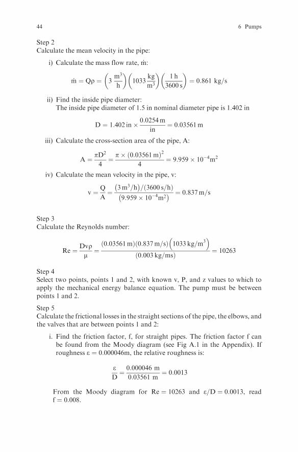
Step 3Calculate the Reynolds number:
Re ¼ Dvrm¼
0:03561mð Þ 0:837m=sð Þ 1033 kg=m3� �
0:003 kg=msð Þ ¼ 10263
Step 4Select two points, points 1 and 2, with known v, P, and z values to which toapply the mechanical energy balance equation. The pump must be betweenpoints 1 and 2.
Step 5Calculate the frictional losses in the straight sections of the pipe, the elbows, andthe valves that are between points 1 and 2:
i. Find the friction factor, f, for straight pipes. The friction factor f canbe found from the Moody diagram (see Fig A.1 in the Appendix). Ifroughness e ¼ 0:000046m, the relative roughness is:
eD¼ 0:000046 m
0:03561 m¼ 0:0013
From the Moody diagram for Re ¼ 10263 and e=D ¼ 0:0013, readf ¼ 0:008.
44 6 Pumps
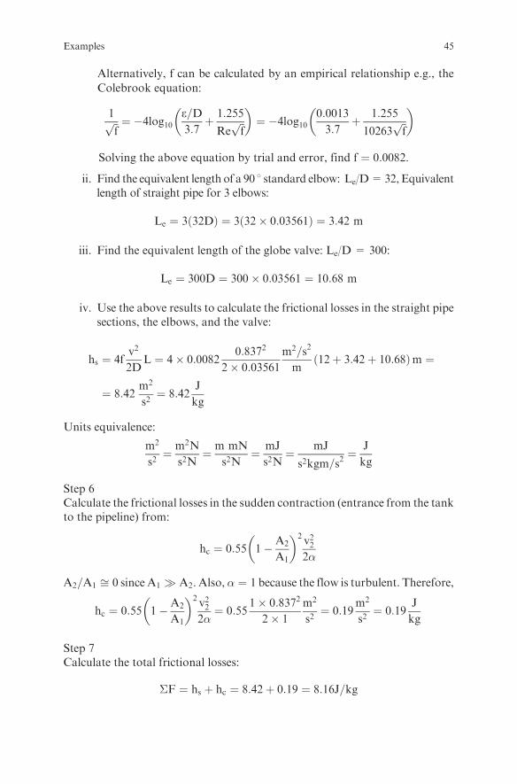
Alternatively, f can be calculated by an empirical relationship e.g., the
Colebrook equation:
1ffiffifp ¼ �4log10
e=D3:7þ 1:255
Reffiffifp
� �¼ �4log10
0:0013
3:7þ 1:255
10263ffiffifp
� �
Solving the above equation by trial and error, find f ¼ 0:0082.
ii. Find the equivalent length of a 90 8 standard elbow: Le/D=32,Equivalentlength of straight pipe for 3 elbows:
Le ¼ 3 32Dð Þ ¼ 3ð32� 0:03561Þ ¼ 3:42 m
iii. Find the equivalent length of the globe valve: Le/D = 300:
Le ¼ 300D ¼ 300� 0:03561 ¼ 10:68 m
iv. Use the above results to calculate the frictional losses in the straight pipesections, the elbows, and the valve:
hs ¼ 4fv2
2DL ¼ 4� 0:0082
0:8372
2� 0:03561
m2=s2
m12þ 3:42þ 10:68ð Þm ¼
¼ 8:42m2
s2¼ 8:42
J
kg
Units equivalence:
m2
s2¼ m2N
s2N¼ m mN
s2N¼ mJ
s2N¼ mJ
s2kgm=s2¼ J
kg
Step 6Calculate the frictional losses in the sudden contraction (entrance from the tankto the pipeline) from:
hc ¼ 0:55 1�A2
A1
� �2v222�
A2=A1 ffi 0 since A1 � A2. Also, � ¼ 1 because the flow is turbulent. Therefore,
hc ¼ 0:55 1�A2
A1
� �2v222�¼ 0:55
1� 0:8372
2� 1
m2
s2¼ 0:19
m2
s2¼ 0:19
J
kg
Step 7Calculate the total frictional losses:
�F ¼ hs þ hc ¼ 8:42þ 0:19 ¼ 8:16J=kg
Examples 45
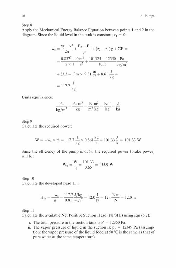
Step 8Apply the Mechanical Energy Balance Equation between points 1 and 2 in thediagram. Since the liquid level in the tank is constant, v1 = 0:
�ws ¼v22 � v212�
þ P2 � P1
�þ z2 � z1ð Þ gþ �F ¼
¼ 0:8372 � 0
2� 1
m2
s2þ 101325� 12350
1033
Pa
kg=m3
þ 3:3� 1ð Þm� 9:81m
s2þ 8:61
J
kg¼
¼ 117:7J
kg
Units equivalence:
Pa
kg=m3¼ Pa m3
kg¼ N
m2
m3
kg¼ Nm
kg¼ J
kg
Step 9Calculate the required power:
W ¼ �ws � _m ¼ 117:7J
kg� 0:861
kg
s¼ 101:33
J
s¼ 101:33 W
Since the efficiency of the pump is 65%, the required power (brake power)will be:
Wa ¼W
Z¼ 101:33
0:65¼ 155:9 W
Step 10Calculate the developed head Hm:
Hm ¼�ws
g¼ 117:7
9:81
J=kg
m=s2¼ 12:0
J
N¼ 12:0
Nm
N¼ 12:0m
Step 11Calculate the available Net Positive Suction Head (NPSHa) using eqn (6.2):
i. The total pressure in the suction tank is P = 12350 Pa.ii. The vapor pressure of liquid in the suction is: pv = 12349 Pa (assump-
tion: the vapor pressure of the liquid food at 50 8C is the same as that ofpure water at the same temperature).
46 6 Pumps

iii. The frictional losses in the suction line are:
a) Frictional losses in the straight pipe section and the elbow of thesuction line:The straight pipe section of the suction line is 2 m.The equivalent straight pipe length of one 908 standard elbow for Le/
D=32, as found in step 5, is
Le ¼ 1ð32DÞ ¼ 32� 0:03561 ¼ 1:14 m
Therefore,
hss ¼ 4fv2
2DL ¼ 4� 0:0082
0:8372
2� 0:035612þ 1:14ð Þ ¼ 1:01
J
kg
b) Frictional losses in the entrance from the tank to the pipeline:
hc ¼ 0:19J=kg ðas calculated in step 6Þ
c) Total losses in the suction line:
�Fs ¼ hss þ hc ¼ 1:01þ 0:19 ¼ 1:2 J=kg
iv) Substitute values in eqn (6.2) and calculate NPSHa :
NPSHa ¼12350� 12349
1033� 9:81þ 1� 1:20
9:81¼ 0:88 m
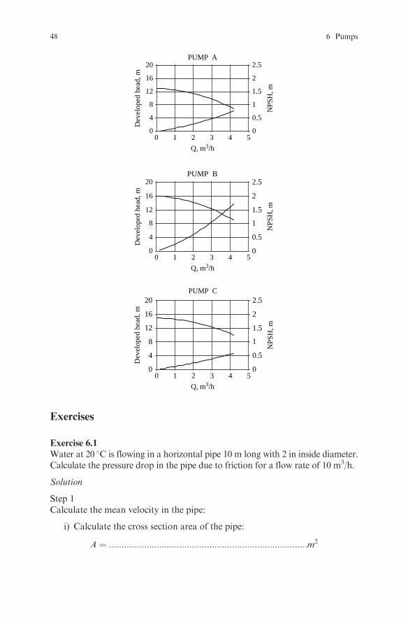
Step 12Select the pump:
Find the volumetric flow rate for each one of the pumps A, B, and C for a
developed head of 12 m. Find also the required NPSH at the corresponding
flow rate:
l Pump A: gives 1.6 m3/h and requires 0.20 m NPSH. Therefore, itdoes not give the required flow rate of 3 m3/h when the developedhead is 12 m.
l Pump B: gives 3.1 m3/h and requires 1.05 m NPSH. Therefore, it givesthe required flow rate of 3 m3/h, but requires more NPSH than theavailable of 0.81 m. If used, it will cavitate.
l Pump C: gives 3.2 m3/h and requires 0.45 m NPSH. Therefore, it givesthe required flow rate of 3 m3/h and requires less NPSH than theavailable of 0.81 m. Therefore, Pump C is suitable for this pumping job.
Examples 47
Q, m3/h
NPS
H, m
Dev
elop
ed h
ead,
m
PUMP A
00
4
8
12
16
20
0
0.5
1
1.5
2
2.5
1 2 3 4 5
NPS
H, m
Dev
elop
ed h
ead,
m
PUMP B
0
4
8
12
16
20
0
0.5
1
1.5
2
2.5
Q, m3/h0 1 2 3 4 5
NPS
H, m
PUMP C
0
4
8
12
16
20
0
0.5
1
1.5
2
2.5
Q, m3/h0 1 2 3 4 5
Dev
elop
ed h
ead,
m
Exercises
Exercise 6.1
Water at 20 8C is flowing in a horizontal pipe 10 m long with 2 in inside diameter.Calculate the pressure drop in the pipe due to friction for a flow rate of 10 m3/h.
Solution
Step 1Calculate the mean velocity in the pipe:
i) Calculate the cross section area of the pipe:
A ¼ :::::::::::::::::::::::::::::::::::::::::::::::::::::::::::::::::::::::::::::::m2
48 6 Pumps
ii) Calculate the mean velocity in the pipe, v:
v ¼ :::::::::::::::::::::::::::::::::::::::::::::::::::::::::::::::::::::::::::::::::::m=s
Step 2Calculate the Reynolds number (find density and viscosity of water from a tablewith physical properties of water):
Re ¼ :::::::::::::::::::::::::::::::::::::::::::::::::::::::::::::::::::::::::::::::::::::::::::::::::::
Step 3Calculate the pressure drop from theFanning equation (since the flow is turbulent):
i) Find the friction factor f from the Moody diagram or from Colebrookequation:
f ¼ ::::::::::::::::::::::::::::::::
ii) Calculate the pressure drop:
�P ¼ 4f�L
D
v2
2¼ :::::::::::::::::::::::::::::::::::::::::::::::::::::::::::::::::::::::::::::Pa
Exercise 6.2
You have available a 550 W pump with 70% efficiency. Is it possible to use this
pump to transfer 10m3/h of a liquid through a 4.7 cm inside diameter pipe, from
one open tank to another, if the liquid is discharged at a point 10 m above the
liquid level in the suction tank and the total friction losses are 50 J/kg? The
density and the viscosity of the liquid are 1050 kg/m3 and 2 cp respectively.
Solution
Step 1Draw the process diagram.
Step 2State your assumptions.:::::::::::::::::::::::::::::::::::::::::::::::::::::::::::::::::::::::::::::::::::::::::::::::::::::::::::::::::
Step 3Select points 1 and 2.
Step 4Calculate the Reynolds number.
i) Calculate the cross section area of the pipe, A:
A ¼ ::::::::::::::::::::::::::::::::::::::::::::::::::::::::::::::::::::m2
Exercises 49

ii) Calculate the mean velocity in the pipe, v:
v ¼ ::::::::::::::::::::::::::::::::::::::::::::::::::::::::::::::::::::::m=s
iii) Calculate the Reynolds number:
Re ¼ ::::::::::::::::::::::::::::::::::::::::::::::::::::::::::::::::::::::::::::::::::::::
Since the flow is turbulent, a = ...........................
Step 5Apply the Mechanical Energy Balance Equation between points 1 and 2.
�ws ¼ ::::::::::::::::::::::::::::::::::::::::::::::::::::::::::::::::::::::::::::::::::::
¼ :::::::::::::::::::::::::::::::::::::::::::::::::::::::::::::::::::::::::::::::::::::
:::::::::::::::::::::::::::::::::::::::::::::::::::::::::::::::::::::::::: ¼ 149J
kg
Step 6Calculate the power.
�Ws ¼ �ws � _m ¼ :::::::::::::::::::::::::::::::::::::::::::::::::::::::::::::::::::::::::: W
For a 70% pump efficiency, the required power (brake power) will be:
WsR ¼::::::::::::::::::
:::::::::::::::¼ 622 W
Since the required power is higher than the available 550 W, the pump is not
suitable for this pumping job.
Exercise 6.3
Apower-law fluid with consistency indexK=0.223 Pa s0.59, flow behavior index n
= 0.59, and density r=1200 kg/m3 is pumped through a sanitary pipe having an
inside diameter of 0.0475m at a rate of 5 m3/h from a tankA to a tank B. The level
of the liquid in tankA is 2mbelow the pump,while the discharge point is 4mabove
the pump. The suction line is 3 m long with one 90 8 elbow, while the discharge lineis 6 m long with two 90 8 elbows. Calculate the developed head and the discharge
pressure of the pump. It is given that the pump is a self-priming pump.
Solution
Step 1Draw the process diagram.
50 6 Pumps

Ws
x 2
Level of reference
x1
A
B
3v3, P3
v2, P2
v1, P1z1
z2
Step 2Calculate the Reynolds number.
i) Calculate the mass flow rate, _m:
_m ¼ Qr ¼ ::::::::::::::::::::::::::::::::::::::::::::::::::::::::::::::: kg=s
ii) Calculate the cross-section area of the pipe, A:
A ¼ ::::::::::::::::::::::::::::::::::::::::::::::::::::::::::::::::::::m2
iii) Calculate the mean velocity in the pipe, v :
v ¼ ::::::::::::::::::::::::::::::::::::::::::::::::::::::::::::::::::::::m=s
iv) Calculate the Generalized Reynolds number:
ReG ¼Dnv2�nr
8n�1 3nþ14n
� �nK
¼0:0475mð Þ0:59 ::::::::::::::::m=sð Þ2�0:59 :::::::::::::::::: kg=m3
� �
:::::::::::::::::::::::::::::::::::::::::::::::::::::
¼ :::::::::
Step 2Calculate the frictional losses in the straight pipe sections, the elbows, andthe valve.
i) Find the friction factor f.
The friction factor can be calculated from f = 16/ReG in laminar flow
or the empirical relationships ofDodge andMetzner (Ref. 1) in turbulent
flow.
Exercises 51

1ffiffifp ¼ 4
n0:75log10 ReG fð Þ1�n=2
� �� 0:4
n1:2¼ ::::::::::::::::::::::::::::::
:::::::::::::::::::::::::::::::::::::::::::::::::::::::::::::::::::::::::::::::::::::::::::
ii) Find the equivalent length of a 90 8 standard elbow: Le=D ¼ 32
Equivalent length of straight pipe for 3 elbows: Le ¼ ::::::::::: m
iii) Find the equivalent length of the globe valve: Le=D ¼ 300
Equivalent length of straight pipe for 1 globe valve Le ¼ ::::: m
iv) Calculate the frictional losses in the straight pipe sections, the elbows,and the valve:
hs ¼ :::::::::::::::::::::::::::::::::::::::::::::::::::::::::::::::::::::::::::::::::
:::::::::::::::::::::::::::::::::::::::::::::::::::::::::::::::::::::::::::::::::::::::J
kg
Step 3Calculate the frictional losses in the sudden contraction.Since the flow islaminar, the kinetic energy correction coefficient is:
a ¼ 2nþ 1ð Þ 5nþ 3ð Þ3 3nþ 1ð Þ2
¼ :::::::::::::::::::::::::::::::::::::::::::::::
hc ¼ ::::::::::::::::::::::::::::::::::::::::::::::::::::::::::::::::::::::::::::::J
kg
Step 4Calculate the total frictional losses.
Ft ¼ ::::::::::::::::::::::::::::::::::::::::::::::::::::::::::::::::::::::::::::: Jkg
Step 5Apply the Mechanical Energy Balance Equation between points 1 and 2 in thediagram. Since the liquid level in the tank is constant, v1=0.
52 6 Pumps
� ws ¼
¼ :::::::::::::::::::::::::::::::::::::::::::::::::::::::::::::::::::::::::::::::::::::::::::¼
¼ ::::::::::::::::::::::::::::::::::::::::::::::::: Jkg
Step 6Calculate the required power.
�Ws ¼ �ws � _m ¼ ::::::::::::::::::::::::::::::::::::::::::::::::::::::::::::::: W
For a 70% pump efficiency, the required power (brake power) will be:
Wa ¼�Ws
Z¼ ::::::::::::::::::::::::::::::::::::::::::: W
Step 7Calculate the developed head Hm.
Hm ¼�ws
g¼ :::::::::::::::::::::::::::::::::::::::::::::::::::::::::::::::::m
Step 8Calculate the discharge pressure.Apply the Mechanical Energy Balance Equa-tion (MEBE) between points 2 and 3 with v2 ¼ v3, z3 ¼ 0, and � ws ¼ 0:
P3
r¼ P2
rþ z2 gþ Fd
where Fd = the friction losses in the discharge line.
P3 ¼ :::::::::::::::::::::::::::::::::::::::::::::::::::::::::::::::::::::::::::::::::::::: ¼
¼ ::::::::::::::::::Pa
Exercise 6.4
Study the spreadsheet program given in Pump.xls to get familiar with the way
the programworks.Modify the spreadsheet program given in Pump.xls to solve
Example 6.1:
a) if a heat exchanger, which gives a pressure drop of 50 kPa, is included inthe discharge line;
Exercises 53

b) if the pump is 1 m above the liquid level in the suction tank (is thispumping possible?); and
c) If the required NPSH is 1 m and the absolute pressure in tank A is101325 kPa, how many meters below the pump could the suction levelbe without having cavitation problems? If the pump was pumping waterat 218C from a well, how many meters below the pump could the suctionlevel be without having cavitation problems?
Exercise 6.5
Study the spreadsheet program given in PumpQ.xls to get familiar with the waythe program works. Run the program and see how the friction losses, therequired power, and the developed head increase with increasing flow rate.Modify the spreadsheet so that instead of variable flow rate, it has variableinside pipe diameter with constant flow rate.
54 6 Pumps

Chapter 7
Heat Transfer by Conduction
Theory
As with all transport phenomena, the rate of the transferred quantity is propor-tional to the driving force and inversely proportional to the resistance. For heat
transfer by conduction, the driving force is the temperature difference �T andthe resistance R ¼ �x=kA, where �x is the wall thickness, k is the thermalconductivity and A is the surface area perpendicular to the direction of transfer.
For a cylindrical wall, A is equal to the logarithmic mean surface area, while fora spherical wall, A is equal to the geometric mean surface area. Thus:
Rate of heat transfer
For a single wallq ¼ �T
R
For a composite wallq ¼ �TP
R
Resistance to heat transfer
Resistance, R Surface area, A
Plane wall �x=kA A
Cylindrical wall �r=kALM ALM ¼A1 �A2
ln A1=A2
Spherical wall �r=kAG AG ¼ffiffiffiffiffiffiffiffiffiffiffiffiA1A2
p
Review Questions
Which of the following statements are true and which are false?
1. Heat is conducted in solids, liquids, and gases by the transfer of the energy ofmotion from one more energetic molecule to an adjacent less energetic one.
S. Yanniotis, Solving Problems in Food Engineering.� Springer 2008
55

2. Fourier’s law is the basic relationship for heat transfer by conduction.3. Resistance to heat transfer is proportional to thermal conductivity.4. Air has low thermal conductivity.5. Metals have higher thermal conductivity than non-metals.6. Ice has a thermal conductivity much higher than water.7. The thermal conductivity of gases is higher than the thermal conductivity of
solids.8. Thermal conductivity is a weak function of temperature.9. In all cases, thermal conductivity varies with temperature gradient.
10. At steady state, the rate of heat transfer is always zero.11. At steady state, the temperature at various points in a system does not
change with time12. At steady state, the temperature at various points in a system may change
with position.13. The temperature gradient is positive.14. For the same heat transfer rate, the slope of the temperature gradientin
insulating materials is smaller than in non-insulating materials.15. The temperature distribution in a plane wall varies linearly with distance in
the wall if there is no heat generation in the wall and the thermal conduc-tivity is constant.
16. The temperature distribution in a cylindrical wall varies logarithmicallywith the distance in the wall if there is no heat generation in the wall and thethermal conductivity is constant.
17. The arithmetic mean area differs from the logarithmic mean area by lessthan 1.4% if A2/A1 < 1.5.
18. In a composite wall at steady state, the heat transfer rate in each layerdepends on the thermal conductivity of the layer.
19. The temperature drop in a plane wall is inversely proportional to theresistance.
20. The slope of the temperature gradient in each layer of a composite planewall depends on the thermal conductivity of the layer.
Examples
Example 7.1
Calculate the rate of heat transfer through a glass window with 3 m2 surface
area and 5 mm thickness if the temperature on the two sides of the glass is 14 8Cand 15 8C respectively and the thermal conductivity of the glass is 0.7 W/m 8C.The system is at steady state.
Solution
56 7 Heat Transfer by Conduction
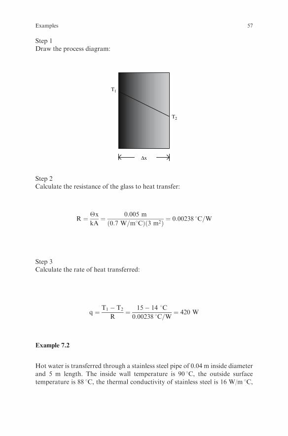
Step 1Draw the process diagram:
T1
T2
Δx
Step 2Calculate the resistance of the glass to heat transfer:
R ¼ �x
kA¼ 0:005 m
0:7 W=m8Cð Þ 3 m2ð Þ ¼ 0:00238 8C=W
Step 3Calculate the rate of heat transferred:
q ¼ T1 � T2
R¼ 15� 14 8C
0:00238 8C=W¼ 420 W
Example 7.2
Hot water is transferred through a stainless steel pipe of 0.04 m inside diameter
and 5 m length. The inside wall temperature is 90 8C, the outside surface
temperature is 88 8C, the thermal conductivity of stainless steel is 16 W/m 8C,
Examples 57
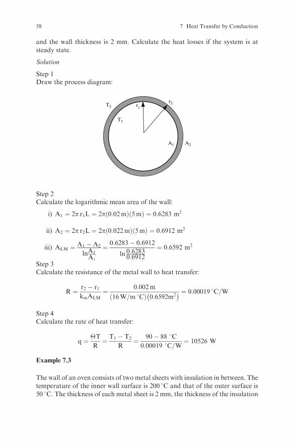
and the wall thickness is 2 mm. Calculate the heat losses if the system is at
steady state.
Solution
Step 1Draw the process diagram:
r2r1
A1 A2
T1
T2
Step 2Calculate the logarithmic mean area of the wall:
i) A1 ¼ 2p r1L ¼ 2p 0:02mð Þ 5mð Þ ¼ 0:6283 m2
ii) A2 ¼ 2p r2L ¼ 2p 0:022mð Þ 5mð Þ ¼ 0:6912 m2
iii) ALM ¼ A1 �A2
lnA1A2
¼ 0:6283� 0:6912
ln 0:62830:6912
¼ 0:6592 m2
Step 3Calculate the resistance of the metal wall to heat transfer:
R ¼ r2 � r1kmALM
¼ 0:002m
16W=m 8Cð Þ 0:6592m2� � ¼ 0:00019 8C=W
Step 4Calculate the rate of heat transfer:
q ¼ �T
R¼ T1 � T2
R¼ 90� 88 8C
0:00019 8C=W¼ 10526 W
Example 7.3
The wall of an oven consists of two metal sheets with insulation in between. The
temperature of the inner wall surface is 200 8C and that of the outer surface is
50 8C. The thickness of each metal sheet is 2 mm, the thickness of the insulation
58 7 Heat Transfer by Conduction

is 5 cm, and the thermal conductivity is 16 W/m 8C and 0.055 W/m 8C respec-
tively. Calculate the total resistance of the wall to heat transfer and the heat
transfer losses through the wall per m2 of wall area.
Solution
Step 1Draw the process diagram:
T1 T2
T3T4
Δx3Δx2Δx1
Step 2State your assumptions.The system is at steady state.
Step 3Calculate the resistance to heat transfer:
i) Inner metal wall
R1 ¼�x1k1A
¼ 0:002m
16W=m8Cð Þ 1m2ð Þ ¼ 0:00013 8C=W
ii) Insulation:
R2 ¼�x2k2A
¼ 0:05m
0:055W=m8Cð Þ 1m2ð Þ ¼ 0:90909 8C=W
iii) Outer metal wall:
R3 ¼�x3k3A
¼ 0:002m
16W=m8Cð Þ 1m2ð Þ ¼ 0:00013 8C=W
Examples 59
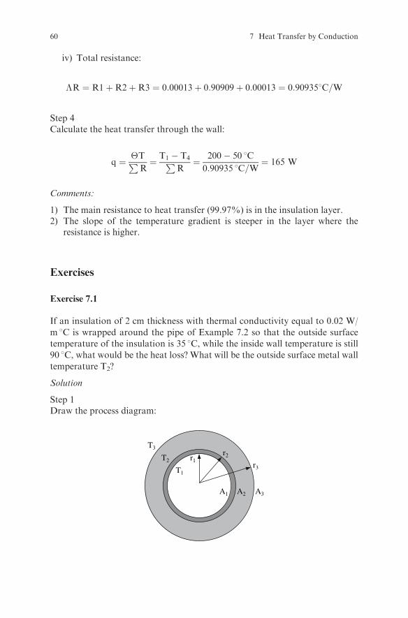
iv) Total resistance:
�R ¼ R1þR2þR3 ¼ 0:00013þ 0:90909þ 0:00013 ¼ 0:909358C=W
Step 4Calculate the heat transfer through the wall:
q ¼ �TPR¼ T1 � T4P
R¼ 200� 50 8C
0:90935 8C=W¼ 165 W
Comments:
1) The main resistance to heat transfer (99.97%) is in the insulation layer.2) The slope of the temperature gradient is steeper in the layer where the
resistance is higher.
Exercises
Exercise 7.1
If an insulation of 2 cm thickness with thermal conductivity equal to 0.02 W/
m 8C is wrapped around the pipe of Example 7.2 so that the outside surface
temperature of the insulation is 35 8C, while the inside wall temperature is still
90 8C, what would be the heat loss? What will be the outside surface metal wall
temperature T2?
Solution
Step 1Draw the process diagram:
r2r1
A1 A2
T1
T2r3
A3
T3
60 7 Heat Transfer by Conduction

Step 2Calculate the logarithmic mean area of the insulation:
iÞ A3 ¼ ::::::::::::::::::::::::::::::::::::::::::::::::::::::::::::::: m2
iiÞ ALMi ¼ :::::::::::::::::::::::::::::::::::::::::::::::::::::::::::: m2
Step 3Calculate the resistance of the insulation layer to heat transfer:
R ¼ ::::::::::::::::::::::::::::::::::::::::::::::::::::::::::::::::::: 8C=W
Step 4Calculate the total resistance:
XR ¼ :::::::::::::::::::::::::::::::::::::::::::::::::
Step 5Calculate the rate of heat transfer:
q ¼ �TPR¼ :::::::::::::::::::::::::::::::::::::::::::::::::::::::::::::::::: W
Step 6Calculate temperature T2.
The temperature drop is proportional to the resistance:
T1 � T2
T1 � T3¼ RwP
R
where Rw is the metal wall resistance.
Therefore,
T2¼::::::::::::::::::::::::::::::::::::::::::::::::::::::::::::::::::::::::8C
Exercise 7.2
The wall of a refrigerator of 4 m2 surface area consists of two metal sheets with
insulation in between. The temperature of the inner wall surface is 5 8C and that
Exercises 61

of the outer surface is 20 8C. The thermal conductivity of the metal wall is 16W/
m 8C and that of the insulation is 0.017 W/m 8C. If the thickness of each metal
sheet is 2 mm, calculate the thickness of the insulation that is required so that
the heat transferred to the refrigerator through the wall is 10 W/m2.
Solution
Step 1Draw the process diagram:
T1 T2
T3T4
Δx3Δx2Δx1
Step 2State your assumptions
....................................................................................................................
Step 3Calculate the resistance to heat transfer:
i) Inner metal wall:
R1 ¼ ::::::::::::::::::::::::::::::::::::::::::::::::::::::: 8C=W
ii) Insulation:
R2 ¼ :::::::::::::::::::::::::::::::::::::::::::::::::::::::::: 8C=W
iii) Outer metal wall:
R3 ¼ ::::::::::::::::::::::::::::::::::::::::::::::::::::::::::::::::::::::::: 8C=W
iv) Total resistance:
XR ¼ :::::::::::::::::::::::::::::::::::::::::::::::::::::::::::::::::::::::::::8C=W
62 7 Heat Transfer by Conduction
Step 4Calculate the thickness of insulation:Since
XR ¼ �T
q¼ ::::::::::::::::::::::::::::::::::::::::::::::::::::::
:::::::::::::::::::::::::::::::::::::::::::::::::::::::8C=W
the thickness of the insulation will be
�x2 ¼ ::::::::::::::::::::::::::::::::::::::::::::::::::::::::::m
Exercise 7.3
A layer of fat 5 mm thick underneath the skin covers a part of a human body. If
the temperature of the inner surface of the fat layer is 36.6 8C and the body loses
heat at a rate of 200 W/m2, what will be the temperature at the surface of the
skin? Assume that the thermal conductivity of fat is 0.2 W/m 8C.
Solution
Step 1State your assumptions:
..................................................................................................................
Step 2Calculate the resistance to heat transfer:
R ¼ ::::::::::::::::::::::::::::::::::::::::::::::::::::::::::::::::::::::::::::::8C=W
Step 3Calculate the surface temperature:Since
q ¼ �T
R
the surface temperature of the skin will be
T2 ¼ ::::::::::::::::::::::::::::::::::::::::::::::::::::::::8C
Exercise 7.4
A composite plane wall consists of two layers A and B. The thermal conductiv-
ity of layers A and B are 0.02 W/m 8C and 15W/m 8C respectively. If 100W/m2
are transferred through the wall at steady state, calculate the temperature
gradient in the two layers.
Exercises 63
Solution
Step 1State your assumptions:
......................................................................................................................
Step 2From Fourier’s law:
dT
dx¼ :::::::::::::::::::::::::::::::::::::::::::::::::
Therefore,
dT
dx
� �A
¼:::::::::::::::::::::::::::::::::::::::::::::::::::::::::::::::::::::::8C=m
and
dT
dx
� �B
¼ ::::::::::::::::::::::::::::::::::::::::::::::::::::::::::::::8C=m
Exercise 7.5
Find an analytical expression to calculate the heat flux in a plane wall if thethermal conductivity varies with temperature according to the equationk=koþaT.
Solution
Step 1Use the expression for k in Fourier’s law:
q
A¼ �kdT
dx¼ � koþaTð Þ dT
dx
Step 2Separate the variables and integrate from x1 to x2 and T1 to T2:
Exercise 7.6
Develop a spreadsheet program to plot the temperature distribution in a planewall, a cylindrical wall, and a spherical wall of 4 cm thickness if the outer surfaceof the wall is at 20 8C and the inner surface is at 200 8C. The inner wall radius forthe cylinder and the sphere is 0.1 m, the outer wall radius is 0.14 m, and thethermal conductivity of the wall is 0.02 W/m 8C. Assume steady state.
64 7 Heat Transfer by Conduction

Hint:The relationships that give the temperature variation as a function of distance ina wall are:
i) Plane wall:
T ¼ T1 �x� x1kA
q ¼ T1 �x
x2 � x1�T
ii) Cylindrical wall:
T ¼ T1 �ln r=r1ð Þ2pkL
q ¼ T1 �ln r=r1ð Þln r2=r1ð Þ�T
iii) Spherical wall:
T ¼ T1 �1r1 �
1r
4pkq ¼ T1 �
1� r1r
1� r1r2
�T
Exercise 7.7
Develop a spreadsheet program to plot the temperature distribution in a planewall of 4 cm thickness and inner wall surface temperature of 200 8C, at steadystate, when a) the thermal conductivity of the wall in W/m 8C varies accordingto the equation k = 0.0325þ0.0004T and 250 W/m2 of heat are transferredthrough the wall; and b) the thermal conductivity is constant and equal to theaverage value for the temperature range of the wall calculated in case a.Calculate the heat transfer rate in case b and compare it to the heat transferrate of case a.
Hint:Calculate the temperature as a function of distance in the wall using theexpression developed in Exercise 7.5.
Exercises 65

Chapter 8
Heat Transfer by Convection
Theory
For heat transfer by convection, the driving force is the temperature difference
�T, and the resistance R is equal to 1=hA, where h is the heat transfer
coefficient (W/m2 8C ) and A is the surface area (m2) perpendicular to the
direction of transfer.
Heat transfer rateequation Resistance, R
Convection only
q ¼ �TR
1=hA
Convection combinedwith conduction
q ¼ �TPR
Plane wallPR ¼ 1
hiAþPnj¼1
�xjkjAþ 1
hoA
Cylindrical wallPR ¼ 1
hiAiþPnj¼1
�rjkjALM
þ 1
hoAo
where
q = heat transfer rate, WR = resistance to heat transfer, 8C /W�T = temperature difference, 8Ch= heat transfer coefficient, W/m2 8Chi= inside surface heat transfer coefficient, W/m2 8Cho= outside surface heat transfer coefficient, W/m2 8CA= heat transfer surface area, m2
Ai= inside heat transfer surface area, m2
Ao= outside heat transfer surface area, m2
ALM = logarithmic mean of Ai and Ao , m2
�xj and �rj = thickness of layer j, mkj = thermal conductivity of layer j, W/m 8C
S. Yanniotis, Solving Problems in Food Engineering.� Springer 2008
67
The heat transfer coefficient is calculated from relationships of the form:
Nu ¼ f Re;Prð Þ or Nu ¼ f Gr;Prð Þ
where
Nu = Nusselt numberRe = Reynolds numberGr = Grashof numberPr = Prandtl number
To calculate the heat transfer coefficient:
1. Determine if the flow is natural or forced (free or forced convection).2. Identify the geometry of the system.3. Determine if the flow is laminar or turbulent (calculate the Reynolds
number).4. Select the appropriate relationship Nu ¼ f Re;Prð Þ5. Calculate Nu and solve for h.
Review Questions
Which of the following statements are true and which are false ?
1. The rate of heat transfer by convection is calculated using Newton’s law ofcooling.
2. The heat transfer coefficient depends on the physical properties of the fluid,the flow regime, and the geometry of the system.
3. The units of the heat transfer coefficient are W/m 8C.4. The overall heat transfer coefficient has the same units as the local heat
transfer coefficient.5. The resistance to heat transfer by convection is proportional to the heat
transfer coefficient.6. The heat transfer coefficient in gases is usually higher than in liquids.7. The heat transfer coefficient is lower in viscous fluids than in water.8. The heat transfer coefficient in forced convection is higher than in natural
convection.9. The heat transfer coefficient in nucleate boiling is higher than in film
boiling.10. The heat transfer coefficient in dropwise condensation is higher than in film
condensation.11. The movement of a fluid in natural convection results from the differences
in the density of the fluid.12. Fouling increases the overall heat transfer coefficient.
68 8 Heat Transfer by Convection
13. Liquid velocities higher than 1 m/s are usually used to reduce fouling.14. A thermal boundary layer develops on a fluid flowing on a solid surface
when the temperature of the fluid is different from the temperature of thesolid surface.
15. Temperature gradients exist in the thermal boundary layer.16. The Prandtl number represents the ratio of thermal diffusivity to momen-
tum diffusivity.17. The Prandtl number relates the thickness of the hydrodynamic boundary
layer to the thickness of the thermal boundary layer.18. The Grashof number represents the ratio of buoyancy forces to viscous
forces.19. The Grashof number in natural convection plays the role of the Reynolds
number in forced convection.20. The fluid properties at the film temperature are used in calculating the heat
transfer coefficient outside various geometries.21. In heat exchangers, counterflow gives a lower driving force than parallel
flow.22. The logarithmic mean temperature difference is used in heat exchangers as
the driving force for heat transfer.23. The arithmetic mean of �T1 and�T2 differs from their logarithmic mean
by more than 1.4% if �T1=�T2 < 1:5.24. In the case of multiple-pass heat exchangers, the logarithmic mean tem-
perature difference must be multiplied by a correction factor.25. In a plate heat exchanger, the surfaces of the plates have special patterns to
increase turbulence.26. Plate heat exchangers are suitable for viscous fluids.27. Because the distance between the plates in a plate heat exchanger is small,
liquids containing particulates may clog the heat exchanger.28. A shell and tube heat exchanger cannot be used in high pressure
applications.29. Scraped-surface heat exchangers can handle viscous fluids.30. Fins are used on the outside surface of a heat exchanger pipe when the heat
transfer coefficient on the outside surface of the pipe is higher than the heattransfer coefficient inside the pipe.
Examples
Example 8.1
Water flows in a pipe of 0.0475 m inside diameter at a velocity of 1.5 m/s.Calculate the heat transfer coefficient if the temperature of the water is 60 8Cand 40 8C at the inlet and the outlet of the pipe respectively, and the inside walltemperature of the pipe is 35 8C.
Examples 69

Solution
Step 1Draw the process diagram:
60°C 40°C
q
q
Step 2Find the physical properties of the water.
The physical properties must be calculated at the average watertemperature:
Tm ¼60þ 40
2¼ 50 8C
Thus,
r50¼ 988kg=m3
m50¼ 0:549cpm35¼ 0:723cpcp50¼ 4183J=kg8Ck50¼ 0:639W=m8C
Step 3Calculate the Reynolds number:
Re ¼ Dvrm¼
0:0475mð Þ 1:5m=sð Þ 988 kg=m3� �
0:000549 kg=ms¼ 128224
Step 4Identify the regime of heat transfer:
l forced convectionl flow inside a cylindrical pipel turbulent flow
70 8 Heat Transfer by Convection
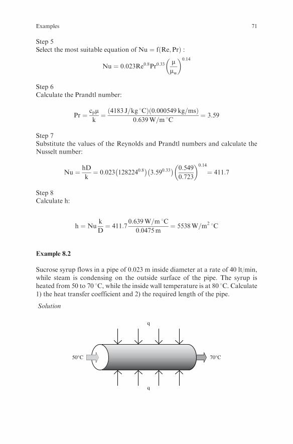
Step 5Select the most suitable equation of Nu ¼ fðRe;PrÞ :
Nu ¼ 0:023Re0:8Pr0:33mmw
� �0:14
Step 6Calculate the Prandtl number:
Pr ¼ cpmk¼ 4183 J=kg 8Cð Þ 0:000549 kg=msð Þ
0:639W=m 8C¼ 3:59
Step 7Substitute the values of the Reynolds and Prandtl numbers and calculate theNusselt number:
Nu ¼ hD
k¼ 0:023 1282240:8
� �3:590:33� � 0:549
0:723
� �0:14
¼ 411:7
Step 8Calculate h:
h ¼ Nuk
D¼ 411:7
0:639W=m 8C0:0475m
¼ 5538W=m2 8C
Example 8.2
Sucrose syrup flows in a pipe of 0.023 m inside diameter at a rate of 40 lt/min,
while steam is condensing on the outside surface of the pipe. The syrup is
heated from 50 to 70 8C, while the inside wall temperature is at 80 8C. Calculate1) the heat transfer coefficient and 2) the required length of the pipe.
Solution
50°C 70°C
q
q
Examples 71
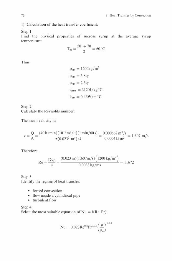
1) Calculation of the heat transfer coefficient:
Step 1Find the physical properties of sucrose syrup at the average syruptemperature:
Tm ¼50 þ 70
2¼ 60 8C
Thus,
r60 ¼ 1200kg�m3
m60 ¼ 3:8cp
m80 ¼ 2:3cp
cp60 ¼ 3120J=kg 8C
k60 ¼ 0:46W=m 8C
Step 2Calculate the Reynolds number:
The mean velocity is:
v ¼ Q
A¼
40 lt=minð Þ 10�3m3=lt� �
1min=60 sð Þp 0:0232 m2� �
=4¼ 0:000667m3=s
0:000415m2¼ 1:607 m=s
Therefore,
Re ¼ Dvrm¼
0:023mð Þ 1:607m=sð Þ 1200 kg=m3� �
0:0038 kg=ms¼ 11672
Step 3Identify the regime of heat transfer:
l forced convectionl flow inside a cylindrical pipel turbulent flow
Step 4Select the most suitable equation of Nu ¼ f Re;Prð Þ:
Nu ¼ 0:023Re0:8Pr0:33mmw
� �0:14
72 8 Heat Transfer by Convection

Step 5Calculate the Prandtl number:
Pr ¼ cpmk¼ 3120 J=kg 8Cð Þ 0:0038 kg=msð Þ
0:460W=m 8C¼ 25:8
Step 6Substitute the values of the Reynolds and Prandtl numbers and calculate theNusselt number:
Nu ¼ hD
k¼ 0:023 116720:8
� �25:80:33� � 3:8
2:3
� �0:14
¼ 129:4
Step 7Calculate h:
h ¼ Nuk
D¼ 129:4
0:460W=m 8C0:023m
¼ 2588 W=m2 8C
2) Calculation of the required pipe length:
Step 1Calculate the heat transferred to the liquid using an enthalpy balance.
i) Write the enthalpy balance:
Hin þ q ¼ Hout
or
_mcpTin þ q ¼ _mcpTout
or
q ¼ _mcp Tout � Tinð Þ (8:1)
Tin Tout
q
q
Examples 73

ii) Calculate the mass flow rate _m (assume that the density of the syrup at508C does not differ significantly from that at 608C):
_m ¼ Qr ¼ 40lt
min
� �1
m3
1000 lt
� �1min
60 s
� �1200
kg
m3
� �¼ 0:8
kg
s
iii) Substitute values into eqn (8.1) and calculate q:
q ¼ _mcp Tout � Tinð Þ ¼ 0:8 kg=sð Þ 3120 J=kg 8Cð Þ 70� 50 8Cð Þ ¼ 49920W(8:2)
Step 2Calculate the heat transferred to the liquid using the heat transfer rateequation:
i) Write the heat transfer rate equation:
q ¼ hADTLM (8:3)
ii) Calculate the driving force for heat transfer DTLMð Þ:
DTLM ¼DT1 � DT2
lnDT1
DT2
¼ 80� 50ð Þ � 80� 70ð Þln 80�5080�70
¼ 18:20 8C
iii) Calculate the heat transfer area:
A ¼ pDL ¼ p 0:023 mð ÞL ¼ 0:0723L m2
iv) Substitute values in eqn (8.3) and calculate q:
q ¼ hADTLM ¼ 2588 W=m2 8C� �
0:0723Lð Þ 18:2 8Cð Þ ¼ 3405:45L (8:4)
Step 3Calculate the required length of the pipe:Since q calculated in eqn (8.2) is equal to q calculated in eqn (8.4),
3405:45L ¼ 49920
Therefore,
L ¼ 14:66m
74 8 Heat Transfer by Convection
Example 8.3
Air is heated by passing over a tube with 0.0127m outside diameter, while steam
is condensing on the inside of the tube. If the heat transfer coefficient on the
airside is 15W�m2 8C, the overall heat transfer coefficient based on the outside
area of the tube is 14:85W�m2 8C, the bulk air temperature is 50 8C, the steam
temperature is 110 8C, and the tube surface temperature on the airside is
109.4 8C, calculate the heat transferred to the air per m of tube length a) using
ho and b) using Uo.
Solution
Step 1Calculate the heat transferred based on ho:
q ¼ Aoho Ttube � Tairð Þ
¼ p 0:0127mð Þ 1mð Þð Þ 15W=m2 8C� �
109:4 8C� 50 8Cð Þ ¼ 35:5W
Step 2Calculate the heat transferred based on Uo:
q ¼ AoUo Tsteam � Tairð Þ
¼ p 0:0127mð Þ 1mð Þð Þ 14:8 5W=m2 8C� �
110 8C� 50 8Cð Þ ¼ 35:5W
Comment: Notice that the temperature at the outside surface of the tube is
required when the local heat transfer coefficient h is used, while the bulk
temperature of the heating medium is required when the overall heat transfer
coefficient U is used.
Exercises
Exercise 8.1
In a fruit packaging house, oranges are washed, dried in a stream of high
speed air at room temperature, waxed, and dried again in a hot air stream.
Calculate the heat transfer coefficient on the surface of an orange if the
air velocity is 10 m/s, the air temperature is 55 8C, the orange surface
temperature is 25 8C, and the orange has a spherical shape with a diameter
of 8 cm.
Exercises 75

Solution
Step 1Find the physical properties of the air.
The physical properties must be calculated at the film temperatureTf (average of air temperature and orange surface temperature).
Tf ¼ :::::::::::::::::::::::::::::::::::::::::::::::::::::::::::::::::::::::::::::::::::8C
Thus
r ¼ ::::::::::::::::::::::::::::::kg�m3
m ¼ ::::::::::::::::::::::::::::::Pas
cp ¼ ::::::::::::::::::::::::::::J=kg 8C
k ¼ ::::::::::::::::::::::::::::W=m�C
Step 2Calculate the Reynolds number:
Re ¼ ::::::::::::::::::::::::::::::::::::::::::::::::::::::::::::::::::::::::::::::::::::::::
Step 3Identify the regime of heat transfer:
l ::::::::::::::::::::::::::::::::::::::::::::::::::::::::::::::::::::::::::l ::::::::::::::::::::::::::::::::::::::::::::::::::::::::::::::::::::::::::l ::::::::::::::::::::::::::::::::::::::::::::::::::::::::::::::::::::::::::
Step 4Select the most suitable equation of Nu ¼ f Re;Prð Þ:
Nu ¼ 2þ 0:60Re0:50Pr0:33
Step 5Calculate the Prandtl number:
Pr ¼ :::::::::::::::::::::::::::::::::::::::::::::::::::::::::::::
Step 6Calculate the Nusselt number:
Nu ¼ :::::::::::::::::::::::::::::::::::::::::::::::::::::::::::::::::::::::::
76 8 Heat Transfer by Convection
Step 7Calculate h:
h ¼ ::::::::::::::::::::::::::::::::::::::::::::::::::::::::::::::::::::::::::::::::::::::::
Exercise 8.2
A horizontal steel pipe with 2 in nominal diameter has an outside surface tem-
perature of 80 8C. Calculate the heat transfer coefficient on the outside surface of
the pipe if the pipe is exposed to a room temperature of 20 8C.
Solution
Step 1Find the physical properties of the air.The physical properties must be calculated at the film temperature Tf (averageof air temperature and pipe surface temperature).
Tf ¼ ::::::::::::::::::::::::::::::::::::::::::::::::::::::::::::::::::::::::::::::::::: 8C
Thus,
r ¼ ::::::::::::::::::::::::::::::kg�m3
m ¼ ::::::::::::::::::::::::::::::Pas
cp ¼ ::::::::::::::::::::::::::::J=kg 8C
k ¼ ::::::::::::::::::::::::::::W=m 8C
Step 2Identify the regime of heat transfer:
l ::::::::::::::::::::::::::::::::::::::::::::::::::::::::::::::::::::::::::::::::::::::::l ::::::::::::::::::::::::::::::::::::::::::::::::::::::::::::::::::::::::::::::::::::::::
Step 3Calculate the Grashof number:Since the pipe is horizontal, the characteristic dimension is the pipe diameter. Ina 2 in nominal diameter steel pipe, the outside diameter is 2.375 in or 0.0603 m.
Therefore,
Gr ¼ D3r2gb�T
m2¼ :::::::::::::::::::::::::::::::::::::::::::::::::::::::::::::::
Step 4Calculate the Prandtl number:
Pr ¼ ::::::::::::::::::::::::::::::::::::::::::::::::::::::::::::::::
Exercises 77
Step 5Select the most suitable equation of Nu ¼ f Gr;Prð Þ:
i) Calculate the product:
Gr � Pr ¼ :::::::::::::::::::::::::::::::::::::::::::::::::::::::::::::::::
ii) Select the equation based on the value of Gr � Pr found above:
Nu ¼ 0:53Gr0:25Pr0:25
Step 6Calculate the Nusselt number:
Nu ¼ :::::::::::::::::::::::::::::::::::::::::::::::::::::::::::::::::::::::::
Step 7Calculate h:
h ¼ :::::::::::::::::::::::::::::::::::::::::::::::::::::::::::::::::::::::::::::
Exercise 8.3
A home heater consists of a vertical plate with dimensions 0:5m� 1:0m. If
the temperature on the surface of the plate is maintained at 70 8C and the
room temperature is equal to 21 8C, calculate the heat transferred to the
room.
Solution
Step 1Find the physical properties of the air at the film temperature Tf:
Tf ¼ ::::::::::::::::::::::::::::::::::::::::::::::::::::::::::::::::::::::::::::::::::: 8C
Thus,
r ¼ ::::::::::::::::::::::::::::::kg�m3
m ¼ ::::::::::::::::::::::::::::::Pas
cp ¼ ::::::::::::::::::::::::::::J=kg 8C
k ¼ ::::::::::::::::::::::::::::W=m 8C
78 8 Heat Transfer by Convection

Step 2Identify the regime of heat transfer:
l ::::::::::::::::::::::::::::::::::::::::::::::::::::::::::::::::::::::::::::::::::::::::l ::::::::::::::::::::::::::::::::::::::::::::::::::::::::::::::::::::::::::::::::::::::::
Step 3Calculate the Grashof number.Since the plate is vertical, the characteristic dimension is the plate height.
Gr ¼ :::::::::::::::::::::::::::::::::::::::::::::::::::::::::::::::
Step 4Calculate the Prandtl number:
Pr ¼ ::::::::::::::::::::::::::::::::::::::::::::::::::::::::::::::::
Step 5Select the most suitable equation of Nu ¼ f Gr;Prð Þ:
i) Calculate the product:
Gr � Pr ¼ :::::::::::::::::::::::::::::::::::::::::::::::::::::::::::::::::
ii) Select the equation suitable for the calculation of the heat transfer coeffi-cient in free convection on a vertical plane with ::::::::::::::::: < Gr�Pr < ::::::::::::::::::::::::
Nu ¼ 0:53Gr0:25Pr0:25
Step 6Calculate the Nusselt number:
Nu ¼ :::::::::::::::::::::::::::::::::::::::::::::::::::::::::::::::::::::::::
Step 7Calculate h:
h ¼ :::::::::::::::::::::::::::::::::::::::::::::::::::::::::::::::::::::::::::::
Step 8Calculate the heat transfer rate:
q ¼ hADT ¼ ::::::::::::::::::::::::::::::::::::::::::::::::::::::::::::::::::
Exercises 79

Exercise 8.4
A liquid food is heated in an unbaffled agitated vessel with a heating jacket. The
inside diameter of the vessel is 1 m and the diameter of the flat-bladed paddle
agitator is 30 cm. The agitator rotates at N ¼ 60rpm. Calculate the heat transfer
coefficient at the wall of the jacket. Assume the following physical properties for
the liquid food: density 1030 kg/m3, viscosity at the bulk liquid temperature
1.5 mPas, viscosity at the wall temperature 1 mPas, heat capacity 4kl=kg 8C,thermal conductivity 0:6W=m 8C. The following correlation can be used for
this case.
Nu ¼ 0:36Re2=3Pr1=3mmw
� �0:21
Solution
Step 1Calculate the Re number (take care with the units):
Re ¼D2
agitatorNr
m¼ :::::::::::::::::::::::::::::::::::::::::::::::::::::::::::::::::::::::::::::::::::::
Step 2Calculate the Prandtl number:
Pr ¼ :::::::::::::::::::::::::::::::::::::::::::::::::::
::::::::::::::::::::::::::::::::::
¼
Step 3Calculate the Nusselt number:
Nu ¼ ::::::::::::::::::::::::::::::::::::::::::::::::::::::::::::::::::::::
80 8 Heat Transfer by Convection

Step 4Calculate the heat transfer coefficient:
h ¼ Nu k
Dvessel¼ :::::::::::::::::::::::::::::::::::::::::::::::::::::::
Exercise 8.5
Orange juice is flowing in a pipe with 0.0229 m inside diameter and 0.0254 m
outside diameter, while steam is condensing on the outside. If the heat
transfer coefficient on the juice side is 1500W�m2 8C, on the steam side
3000W�m2 8C and the thermal conductivity of the tube is 15W
�m 8C, calcu-
late the overall heat transfer coefficient based on the outside area Uo and the
inside area Ui.
Solution
Step 1Draw the process diagram:
Aoho
hiAi
Step 2Calculate the overall heat transfer coefficient based on the outside surface areaof the pipe:
Uo¼1
Ao
PR¼ 1
Ao1
hiAiþ DrkALM
þ 1hoAo
� �¼ 1
Do1
hiDiþ ln Do=Dið Þ
2kþ 1hoDo
� �¼
¼ ::::::::::::::::::::::::::::::::::::::::::::::::::::::::::::::::::::::::::::::::::::::::::::::::::::::::::::
Exercises 81

Step 3Calculate the overall heat transfer coefficient based on the inside surface area ofthe pipe:
Ui ¼1
Ai
PR¼ 1
Ai1
hiAiþ DrkALM
þ 1
hoAo
� � ¼ 1
Di1
hiDiþ ln Do=Dið Þ
2kþ 1
hoDo
� � ¼
¼ ::::::::::::::::::::::::::::::::::::::::::::::::::::::::::::::::::::::::::::::::::::::::::::::::::
Exercise 8.6
Air at a temperature of 60 8C flows inside a pilot plant cabinet dryer withdimensions 1m� 1m� 1m at a velocity of 3m=s. The walls of the dryer consistof two metal sheets of 2 mm thickness with 5 cm insulation in between.Calculate the heat losses through the side walls of the dryer if the heat transfercoefficient on the inside surface of the walls is 15W
�m2 8C, the thermal con-
ductivity of the metal wall and the insulation are 45W=m 8C and 0:045W=m 8Crespectively, and the outside air temperature is 20 8C.
Solution
Step 1Draw the process diagram:
60°C
20°C
hi = 15 W/m2°C ho
Two
Step 2Identify the regime of heat transfer:
l forced convection on the inside surface of the walll conduction through the walll natural convection on the outside surface of the walls
82 8 Heat Transfer by Convection
Step 3Calculate the heat transfer coefficient on the outside surface of the wall:
i) Find the physical properties of the air at the film temperature Tf:Since the wall temperature is not known, it must be assumed. Assume
the outside wall temperature (Two) is 30 8C. This assumption will be
verified later (Step 4).
Tf ¼ :::::::::::::::::::::::::::::::::::::::::::::::::::::::::::::::::::::::::::::::::::8C
Thus,
r ¼ ::::::::::::::::::::::::::::::kg�m3
m ¼ ::::::::::::::::::::::::::::::Pas
cp ¼ ::::::::::::::::::::::::::::J=kg�C
k ¼ ::::::::::::::::::::::::::::W=m�C
b ¼ :::::::::::::::::::::::::::::1=K
ii) Calculate the Grashof number:Since the walls are vertical (side walls), the characteristic dimension is.....................................................................
Therefore:
Gr ¼ :::::::::::::::::::::::::::::::::::::::::::::::::::::::::::::::
iii) Calculate the Prandtl number:
Pr ¼ ::::::::::::::::::::::::::::::::::::::::::::::::::::::::::::::::
iv) Select the most suitable equation of Nu ¼ f Gr;Prð Þ:Calculate the product:
Gr � Pr ¼ :::::::::::::::::::::::::::::::::::::::::::::::::::::::::::::::::
Since 104 < Gr � Pr < 109, the equation suitable for the calculation of the heattransfer coefficient is:
:::::::::::::::::::::::::::::::::::::::::::::::::::::::::::::::::::::::::::::::::::::::::::::
v) Calculate the Nusselt number:
Nu ¼ :::::::::::::::::::::::::::::::::::::::::::::::::::::::::::::::::::::::::
Exercises 83
vi) Calculate h:
h ¼ :::::::::::::::::::::::::::::::::::::::::::::::::::::::::::::::::::::::::::::
Step 4Verify the assumption made in step 3(i) about the outside wall temperature.
a) Calculate the resistances to heat transfer:
i) Convective resistance on the inside wall surface:
Ri ¼1
hiA¼ :::::::::::::::::::::::::::::::::::::::::::::::::::::::::::::::::::::
ii) Conductive resistance of the wall:
Rw ¼X3j¼1
Rj ¼�xmkmA
þ�xikiAþ�xmkmA
¼ :::::::::::::::::::::::::::::::::::::::::
iii) Convective resistance on the outside wall surface:
Ro ¼ :::::::::::::::::::::::::::::::::::::::::::::::::::::::::::::::::::::
iv) Total resistance:
XR ¼ Ri þRw þRo ¼ ::::::::::::::::::::::::::::::::::::::::::::::::::
b) Calculate the temperature drop due to outside convective resistance:
DTo ¼RoPR
�Toverall ¼ ::::::::::::::::::::::::::::::::::::::::::::::::::::::::
c) Calculate the outside wall surface temperature:
Two ¼ Tair þ�To ¼ 20þ 9:6 ¼ 29:6 8C
The calculated Two with the last relationship is very close to the 30 8C that was
assumed in step 3(i). If the Two calculated here was different from the assumed
Two in step 3(i), another temperature should be assumed and the calculations
84 8 Heat Transfer by Convection

should be repeated from step 3(i) onward until the assumed temperature and thecalculated one are very close.
Step 5Calculate the overall heat transfer coefficient:
U ¼ 1
AP
R¼ ::::::::::::::::::::::::::::::::::::::::::::::::::::::::::::::::::
Step 6Calculate the heat losses:
q ¼ AUDToverall ¼ :::::::::::::::::::::::::::::::::::::::::::::::::::::::::::::
Exercise 8.7
Run the spreadsheet program Convection 1.xls. See how the value of h� varieswhen the outside wall surface temperature is adjusted in the cell F34. Adjust thespreadsheet program Convection 1.xls to calculate the heat losses from the side,the upper plane, and the lower plane of the dryer of Exercise 8.6. Compare theresults.Use the following empirical correlations for the physical properties of air as afunction of temperature (in 8C):
Density r ¼ 1:284� 3:9� 10�3Tþ 6:05� 10�6T2 kg�m3
� �Viscosity m ¼ 1:75� 10�5 þ 4:17� 10�8T Pasð Þ
Heat capacity cp ¼ 1004:1þ 4:28� 10�2Tþ 3� 10�4T2 J=kg 8Cð Þ
Thermal conductivity k ¼ 2:441� 10�2 þ 7:12� 10�5T W=m�Cð Þ
Volumetric expansion b ¼ 3:6� 10�3 � 1:1� 10�5Tþ 1:66� 10�8T2 1=Kð Þ
(Hints: Find suitable equations from the literature (e.g., Ref. 2, 3, 4) to calculatethe Nu number for a heated plate facing upward (top side of the dryer) and for aheated plate facing downward (bottom side of the dryer). Introduce the con-stants in the appropriate cells. Write the equations for the overall heat transfercoefficient and the heat transfer rate. Run the program.)
Exercise 8.8
Get familiar with the spreadsheet program Convection 2.xls. Run the program.See how the outside surface temperature of the vertical wall of the dryer ofExercise 8.6 and the heat transfer coefficient ho vary when the inside airtemperature of the dryer varies from 50 8C to 200 8C. Adjust the spreadsheet
Exercises 85
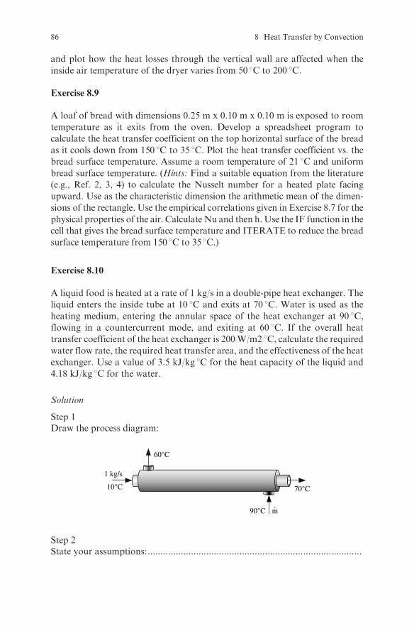
and plot how the heat losses through the vertical wall are affected when the
inside air temperature of the dryer varies from 50 8C to 200 8C.
Exercise 8.9
A loaf of bread with dimensions 0.25 m x 0.10 m x 0.10 m is exposed to room
temperature as it exits from the oven. Develop a spreadsheet program to
calculate the heat transfer coefficient on the top horizontal surface of the bread
as it cools down from 150 8C to 35 8C. Plot the heat transfer coefficient vs. thebread surface temperature. Assume a room temperature of 21 8C and uniform
bread surface temperature. (Hints: Find a suitable equation from the literature
(e.g., Ref. 2, 3, 4) to calculate the Nusselt number for a heated plate facing
upward. Use as the characteristic dimension the arithmetic mean of the dimen-
sions of the rectangle. Use the empirical correlations given in Exercise 8.7 for the
physical properties of the air. Calculate Nu and then h. Use the IF function in the
cell that gives the bread surface temperature and ITERATE to reduce the bread
surface temperature from 150 8C to 35 8C.)
Exercise 8.10
A liquid food is heated at a rate of 1 kg/s in a double-pipe heat exchanger. The
liquid enters the inside tube at 10 8C and exits at 70 8C. Water is used as the
heating medium, entering the annular space of the heat exchanger at 90 8C,flowing in a countercurrent mode, and exiting at 60 8C. If the overall heat
transfer coefficient of the heat exchanger is 200W/m2 8C, calculate the requiredwater flow rate, the required heat transfer area, and the effectiveness of the heat
exchanger. Use a value of 3.5 kJ/kg 8C for the heat capacity of the liquid and
4.18 kJ/kg 8C for the water.
Solution
Step 1Draw the process diagram:
10°C 70°C
60°C
90°C m
1 kg/s
.
Step 2State your assumptions:....................................................................................
86 8 Heat Transfer by Convection

Step 3Write an enthalpy balance on the heat exchanger and calculate the mass flowrate of water:
:::::::::::::::::::::::::::::::::::::::::::::::::::::::::::::::::::::::::::::::::::::::::::::
_m ¼ ::::::::::::::::::::::::
Step 4Calculate the logarithmic mean temperature difference:
�TLM ¼ :::::::::::::::::::::::::::::::::::::::::::::::::::::::::::::::::::::::::::::::::
Step 5Calculate the heat transfer area from the heat transfer rate equation:
A ¼ q
UDTLM¼ :::::::::::::::::::::::::::::::::::::::::::::::::::::::::::::::::::::::::
Step 6Calculate the effectiveness of the heat exchanger:
i) The effectiveness of a heat exchanger is given by (see, for example, Ref. 4):
e ¼ Chot Thot in � Thot outð ÞCmin Thot in � Tcold inð Þ (8:5)
or
e ¼ Ccold Tcold out � Tcold inð ÞCmin Thot in � Tcold inð Þ (8:6)
where
Chot ¼ _mhotcp hot
Ccold ¼ _mcoldcp cold
ii) Calculate Chot and Ccold and determine which one is Cmin:
Chot ¼ ::::::::::::::::::::::::::::::::::::::::::::::::::::::::::::::W= 8C
Ccold ¼ ::::::::::::::::::::::::::::::::::::::::::::::::::::::::::::::W= 8C
Exercises 87

iii) Substitute these values into eqn (8.5) or eqn (8.6) and calculate e:
e ¼ :::::::::::::::::::::::::::::::::::::::::::::::::::::::::::::::::::::::::::::::::::::::::: ¼ ::::::::::::::::::::
Exercise 8.11
If the liquid of Exercise 8.10 is heated in a 1-2 multiple pass shell and tube heat
exchanger, calculate the mean temperature difference and the area of the heat
exchanger. The overall heat transfer coefficient is 250W�m2�C. Use the same
values for the temperature of the liquid food and water.
Solution
Step 1Draw the process diagram:
Step 2Calculate the mean temperature difference:The logarithmic mean temperature difference found for the 1-1 heat exchanger
of Exercise 8.10 must be corrected since the flow is mixed (cocurrent and
countercurrent flow).
i) Calculate the dimensionless ratios:
Thi � Tho
Tco � Tci¼ 90� 60
70� 10¼ 0:5
and
Tco � Tci
Thi � Tci¼ :::::::::::::::::::::::::::::::::::::::::::::::::::::::::::::::::::::::::::::::::
88 8 Heat Transfer by Convection

ii) Find the correction factor from an appropriate diagram from the litera-ture (e.g., Ref. 3, 4).With the above values of the dimensionless ratios, thecorrection factor for a 1-2 heat exchanger is 0.55. Therefore the correctedmean temperature difference is:
DTm ¼ 0:55 � DTLM ¼ :::::::::::::::::::::::::::::::::::::::::::::::::::::::::::::::::::::::::
Step 3Calculate the heat transfer area:
A ¼ :::::::::::::::::::::::::::::::::::::::::::
::::::::::::::::::::::::::::::::::::::::::
¼ ::::::::::::::::::::::::::::::::::::::::::::::::::::::::::
Exercise 8.12
Calculate the mean temperature difference and the area of the heat exchanger ofExercise 8.11 if saturated steam at 101325 Pa absolute pressure is used as theheating medium instead of water. Use the same values for the temperature ofthe liquid food. Assume that the overall heat transfer coefficient in this case is300W
�m2�C.
Solution
Step 1Calculate the mean temperature difference:The temperature of the heating medium is: :::::::::::::::::::::::::::::::::::::::
The correction factor for the mean temperature difference for a multiple-passheat exchanger when one of the fluids undergoes a phase change is 1.Therefore:
�Tm ¼ ::::::::::::::::::::::::::::::::::::::::::::::::::::::::::::::::
Step 2Calculate the heat transfer area:
A ¼ ::::::::::::::::::::::::::::::::::::::::::::::::::::::::::::::::::::::::::::::::::::::::::::::::
Exercise 8.13
Milk is pasteurized at a rate of 1:5kg=s in a plate heat exchanger that consists of aheat regeneration section, a heating section, and a cooling section. The milkenters the regeneration section at 5 8C and exits at 45 8C. It then enters theheating section where it is heated up to 72 8C, flows through the holder, and
Exercises 89

returns to the regeneration section where it is cooled to 32 8C. From the regen-erator, it flows to the cooling section where it is cooled down to 5 8C. Calculate 1)the required heat transfer area of each section, 2) the required flow rate of theheating water in the heating section, and 3) the brine exit temperature in thecooling section. It is given that the streams in each section flow in countercurrentmode; the heating water enters the heating section at 90 8C and exits at 80 8C; thebrine enters the cooling section at –5 8C at a flow rate of 1kg=s; the overall heattransfer coefficients are 1100W
�m2�C for the regenerator, 1300W
�m2�C for the
heating section, and 800W�m2�C for the cooling section; the heat capacities
throughout the process are 3:9kJ�kg �C for the milk, 4:19kJ
�kg �C for the
water, and 3:5kJ�kg �C for the brine.
Solution
Step 1Draw the process diagram:
milk in5°C
milk out
brine in–5°C hot water in
90°C
hot water outbrine out
Holding tube
Regenerationsection
Heatingsection
Coolingsection
5°C
72°C
72°C
80°C
45°C32°C
Step 2Calculate the heat transfer area in the regenerator.
i) Calculate the heat transferred from the hot stream to the cold stream:
qR ¼ _mmcp Thot in � Thot outð Þ ¼ ::::::::::::::::::::::::::::::::::::
ii) Calculate the driving force for heat transfer (mean temperature differ-ence �Tm).Since
�T1 ¼ �T2 ¼ ::::::::::::::::::::::::::::::::::::::::::::::::::::::::::::::
�Tm ¼ �T1 ¼ �T2 ¼ :::::::::::::::::::::::::::::::::::::::::::::::::::
90 8 Heat Transfer by Convection

iii) Calculate the heat transfer area of the regenerator:
AR ¼qR
UR�Tm¼ :::::::::::::::::::::::::::::::::::::::::::::::::::::::::::
Step 3Calculate the heat transfer area in the heating section.
i) Calculate the mass flow rate of water.Write an enthalpy balance aroundthe heating section and calculate mwater.
:::::::::::::::::::::::::::::::::::::::::::::::::::::::::::::::::::::::::::::::::::::::::::::
ii) Calculate the heat transfer area of the heat exchanger in the heatingsection (work as for the regenerator):
:::::::::::::::::::::::::::::::::::::::::::::::::::::::::::::::::::::::::::::::::::::::::::::
:::::::::::::::::::::::::::::::::::::::::::::::::::::::::::::::::::::::::::::::::::::::::::::
:::::::::::::::::::::::::::::::::::::::::::::::::::::::::::::::::::::::::::::::::::::::::::::
Step 4Calculate the heat transfer area in the cooling section.
i) Write an enthalpy balance around the cooling section and calculate thebrine exit temperature:
:::::::::::::::::::::::::::::::::::::::::::::::::::::::::::::::::::::::::::::::::::::::::::::
ii) Calculate the heat transfer area of the heat exchanger in the coolingsection (work as for the regenerator):
:::::::::::::::::::::::::::::::::::::::::::::::::::::::::::::::::::::::::::::::::::::::::::::
:::::::::::::::::::::::::::::::::::::::::::::::::::::::::::::::::::::::::::::::::::::::::::::
:::::::::::::::::::::::::::::::::::::::::::::::::::::::::::::::::::::::::::::::::::::::::::::
Exercises 91

Step 5Write an enthalpy balance in the heating section and calculate the mass flowrate of the heating water:
:::::::::::::::::::::::::::::::::::::::::::::::::::::::::::::::::::::::::::::::::::::::::::::
_mw ¼ ::::::::::::::::::::::::::::::::::::::::::::::
Step 6Calculate the brine exit temperature:
:::::::::::::::::::::::::::::::::::::::::::::::::::::::::::::::::::::::::::::::::::::::::::::
Exercise 8.14
In the previous exercise, calculate: 1) the necessary length of the holding tube so
that at steady state the fastest moving liquid remains in the holding tube for 16 s;
and 2) the required thickness of insulation so that the temperature of the milk
drops by 0.1 8C in the holding tube. The following data are given: the mean
velocity of the liquid is 0.80.vmax, the heat transfer coefficient on the milk side is
1500W�m2 8C and on the airside is 5W
�m2 8C, the thermal conductivity of the
pipe is 15W/m 8C and of the insulation is 0:05W=m 8C, the room temperature is
20 8C, the inside diameter of the pipe is 0.0356m, the thickness of the pipe wall is
1.2 mm, and the density of the milk is 1010kg�m3.
Solution
Step 1
i) Calculate the mean velocity:
v ¼ ::::::::::::::::::::::::::::::::::::::::::::::::::::::::::::::::m=s
ii) Calculate the maximum velocity:
vmax ¼v
0:8¼ :::::::::::::::::::::::::::::::::::::::::::::::::m=s
iii) Calculate the required length:
L ¼ vmaxt ¼ :::::::::::::::::::::::::::::::::::::::::::::::::::::::::::
Step 2Develop a spreadsheet program to calculate the thickness of the insulation byiteration.
92 8 Heat Transfer by Convection

i) Calculate the heat that must be removed so that the temperature of themilk drops by 0.1 8C.
ii) Select a value for the insulation thickness.iii) Calculate the overall heat transfer coefficient.iv) Calculate heat losses with the heat transfer rate equation.v) If heat losses calculated in iv) are higher than those calculated in
i), increase the thickness of the insulation and repeat the calculationsfrom step ii). ITERATE to increase the thickness of insulation until theheat losses calculated in iv) are equal to the heat calculated in i). Use theIF function in the cell that gives the insulation thickness.
Exercise 8.15
The overall heat transfer coefficient based on the outside surface area of the
tubes of a sugar evaporator decreased during operation from 1200W�m2�C to
800W�m2�C due to fouling. Calculate the fouling coefficient.
Solution
Step 1State your assumptions: The effect of fouling on the heat transfer area Ao isnegligible.
Step 2By definition:
Uo ¼1
Ao
PR
orX
R ¼ 1
UoAo
and since resistances are additive:XRfinal ¼
XRinitial þRfouling (8:7)
where
Rfouling ¼1
hfoulingAo
Step 3Substitute into eqn (8.7) and calculate hfouling:
hfouling ¼ ::::::::::::::::::::::::::::::::::::::::::::::::::::::::::::::::::::::W=m2oC
Exercise 8.16
A fouling coefficient of 1990W�m2�C is recommended for use in designing
heat transfer equipment for vegetable oils (see for example Ref. 3, p. 187).
Exercises 93

How much more heat transfer area will be required in a heat exchanger tocompensate for the reduction in the overall heat transfer coefficient due tothis fouling? The overall heat transfer coefficient based on the inside area ofthe tubes for the clean heat exchanger is 300 W/m2 8C.
Solution
Step 1State your assumptions
l The effect of fouling on the diameter of the tubes is negligible.l The heat transfer driving force will be the same in the clean and the
fouled heat exchangers.l The heat transferred will be the same in the clean and the fouled heat
exchangers.
Step 2
i) As shown in Exercise 8.15:
1
Utotal¼ 1
Ucleanþ 1
hfoul
ii) Calculate Utotal:
Utotal ¼ ::::::::::::::::::::::::::::::::::::::::::::::::::::::::::::::::::::::::
Step 3The required heat transfer area for the fouled heat exchanger is:
Afoul ¼q
UtotalDTLM(8:8)
Step 4The required heat transfer area for the clean heat exchanger is:
Ai ¼q
UcleanDTLM(8:9)
Step 5Divide eqn (8.8) by eqn (8.9), substitute values and calculate the increase in heattransfer area:
Afoul
Ai¼ ::::::::::::::::::::::::::::::::::::::::::::::::::::
94 8 Heat Transfer by Convection

Chapter 9
Heat Transfer by Radiation
Review Questions
Which of the following statements are true and which are false?
1. The presence of matter between the points that exchange energy by radia-tion is not necessary.
2. A black body absorbs all the visible light but may reflect other wavelengthsof the incident radiation.
3. The radiation emitted by surfaces at temperatures less than about 800 K isnot visible by the human eye.
4. Ametal rod turns red when heated in a fire because it reaches a temperatureat which it emits radiation visible to the human eye.
5. A leaf is seen as green because it emits radiation at the green wavelength.
6. A surface is seen as white because it reflects all the wavelengths of visiblelight.
7. The Stefan-Boltzman law states that the total radiation from a black bodyis proportional to the square of the absolute temperature of the body.
8. In heat transfer calculations involving radiation, the temperature is usuallyexpressed in degrees Celsius.
9. Emissivity is defined as the ratio of the radiation emitted by a surface to thatemitted by a black body at the same temperature.
10. Absorptivity is defined as the ratio of the radiation absorbed by a surface tothat absorbed by a black body.
11. When a surface is at thermal equilibrium with its surroundings, its emissiv-ity is equal to its absorptivity.
12. Rough surfaces have lower emissivity than polished surfaces.13. The shape factor or view factor is equal to the fraction of radiation leaving
area A1 that is intercepted by area A2.14. The view factor of a small surface surrounded by a large surface is equal to 0.5.15. Surfaces with a high emissivity to absorptivity ratio are suitable for collect-
ing solar energy.
S. Yanniotis, Solving Problems in Food Engineering.� Springer 2008
95

Examples
Example 9.1
A horizontal steel pipe with 2 in outside diameter has an outside surfacetemperature of 150 8C. Calculate the heat losses per m length of pipe, takinginto account convection and radiation losses. Assume that the emissivity of thesurface of the tube is 0.75, the pipe is exposed to a room temperature of 20 8C,and the convective heat transfer coefficient is 15 W/m2 8C.
Solution
Step 1Calculate radiation losses:
i) Assumptions:
l The pipe is considered a small grey body in a large enclosure.l The temperature of the surfaces seen by the pipe is equal to the air
temperature.
ii) The net heat transferred from the pipe to the surroundings by radiation is:
q12 ¼ A1F12s T41 � T4
2
� �(9:1)
with
F12 ¼1
f12 þ 1e1 � 1� �
þA1A2
1e2 � 1� �
Because all the radiation from A1 (the pipe) is intercepted by A2 (thesurrounding walls), f12 = 1. Also, because the surface area of the pipe (A1)is negligible compared to the surface area of the surroundings, A1/A2 � 0.Therefore F12 = e1.
Equation (9.1) then becomes:
q12 ¼ A1e1s T4s � Ta
4� �
(9:2)
Step 2Calculate convection losses:
qc ¼ hcA1 Ts � Tað Þ (9:3)
Step 3Calculate total losses:
q toatl ¼ qcþ qr¼ hcþ hrð ÞA1 Ts�Tað Þ (9:4)
96 9 Heat Transfer by Radiation

where
hr¼e1s T4
s�T4a
� �Ts�Ta
¼0:75ð Þ 5:676� 10�8 W=m2K4
� �4234�2934� �
K4
423� 293ð ÞK
¼8:1W=m2K
Remember that temperature in radiation problems must be in degrees Kelvin.
Step 4Sabstitute values into eqn (9.4) and calculate q total.
q total ¼ 15þ 8:1ð ÞW=m2K � p� 1� 2� 0:0254ð Þm2 423� 293ð ÞK ¼ 479:3W
Exercises
Exercise 9.1
A ‘‘thermos’’ is made of two coaxial glass cylinders with the annular space in
between evacuated to minimize heat transfer to the environment and keep the
contained liquid at a constant temperature (e.g., hot coffee). The glass surfaces
are polished, having an emissivity of 0.095. The diameters of the inner and outer
cylinders are 10 cm and 11 cm respectively and their length is 20 cm. The
temperature of the inner and outer cylinders is 90 8C and 30 8C respectively.
Calculate the rate of heat loss by radiation through the cylindrical surface from
the inner to the outer cylinder.
Solution
Step 1Write the equation for heat transfer by radiation:
The net heat transferred from the inner cylinder to the outer by radiation is:
q12 ¼ A1F12s T41 � T4
2
� �
with
F12 ¼1
f12 þ 1e1 � 1� �
þA1A2
1e2 � 1� � ¼ 1
1e1 � 1� �
þD1D2
1e2 � 1� �
Exercises 97

(Explain why f12 = 1 in the above equation).
Step 2Substitute values and calculate q12:
q12 ¼ :::::::::::::::::::::::::::::::::::::::::::::::::::::::::::::::::::::::::::::::::::::::::::::::
Exercise 9.2
A cookie with 50 cm2 surface area, emissivity equal to 0.85, and surfacetemperature equal to 80 8C is being baked in a domestic oven. Calculate theheat transfer rate to the cookie by radiation if the walls of the oven are at180 8C.
Solution
Step 1State your assumptions: ...................................................................................
Step 2Write the equation for heat transfer by radiation:
q21¼ A2F21s T4w�T4
s
� �¼ A1F12s T4
w�T4s
� �
Step 3Substitute values and calculate q21:
q21 ¼ :::::::::::::::::::::::::::::::::::::::::::::::::::::::::::::::::::::::::::::::::::::::::::::::
98 9 Heat Transfer by Radiation
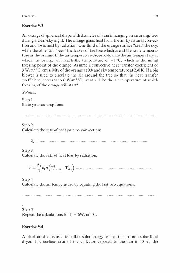
Exercise 9.3
An orange of spherical shape with diameter of 8 cm is hanging on an orange treeduring a clear-sky night. The orange gains heat from the air by natural convec-tion and loses heat by radiation. One third of the orange surface ‘‘sees’’ the sky,while the other 2/3 ‘‘sees’’ the leaves of the tree which are at the same tempera-ture as the orange. If the air temperature drops, calculate the air temperature atwhich the orange will reach the temperature of �1 8C, which is the initialfreezing point of the orange. Assume a convective heat transfer coefficient of3W/m2 8C, emissivity of the orange at 0.8 and sky temperature at 230K. If a bigblower is used to circulate the air around the tree so that the heat transfercoefficient increases to 6 W/m2 8C, what will be the air temperature at whichfreezing of the orange will start?
Solution
Step 1State your assumptions:
::::::::::::::::::::::::::::::::::::::::::::::::::::::::::::::::::::::::::::::::::::::::::::::::::::::::::::::::::::::::::
Step 2Calculate the rate of heat gain by convection:
qc ¼ :::::::::::::::::::::::::::::::::::::::::::::::::::::::::::::::::::::::::::::::::::::::::::::::::::
Step 3Calculate the rate of heat loss by radiation:
qr¼A1
3e1s T4
orange�T4sky
� �¼ ::::::::::::::::::::::::::::::::::::::::::::::::::::::::::::::::
Step 4Calculate the air temperature by equating the last two equations:
::::::::::::::::::::::::::::::::::::::::::::::::::::::::::::::::::::::::::::::::::::::::::::::::::::::::::::::::::::::::::
.Step 5Repeat the calculations for h ¼ 6W=m2 8C.
Exercise 9.4
A black air duct is used to collect solar energy to heat the air for a solar fooddryer. The surface area of the collector exposed to the sun is 10m2, the
Exercises 99
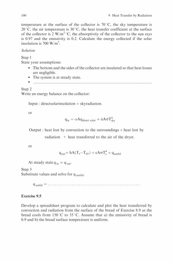
temperature at the surface of the collector is 70 8C, the sky temperature is20 8C, the air temperature is 30 8C, the heat transfer coefficient at the surfaceof the collector is 2 W/m2 8C, the absorptivity of the collector to the sun raysis 0.97 and the emissivity is 0.2. Calculate the energy collected if the solarinsolation is 700 W/m2.
Solution
Step 1State your assumptions:
l The bottom and the sides of the collector are insulated so that heat lossesare negligible.
l The system is at steady state.l ...............................................................................................................
Step 2Write an energy balance on the collector:
Input : directsolarinsolationþ skyradiation:
or
qin ¼ �Aqdirect solar þ aAsT4sky
Output : heat lost by convection to the surroundingsþ heat lost by
radiation + heat transferred to the air of the dryer.
or
qout¼ hA Ts�Tairð Þ þ eAsT4s þ quseful
At steady state q in ¼ qout:
Step 3Substitute values and solve for quseful.
quseful ¼ . . . . . . . . . . . . . . . . . . . . . . . . . . . . . . . . . . . . . . . . . . . . . . . . . . . . . .
Exercise 9.5
Develop a spreadsheet program to calculate and plot the heat transferred byconvection and radiation from the surface of the bread of Exercise 8.9 as thebread cools from 150 8C to 35 8C. Assume that a) the emissivity of bread is0.9 and b) the bread surface temperature is uniform.
100 9 Heat Transfer by Radiation
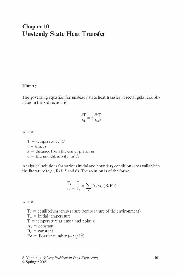
Chapter 10
Unsteady State Heat Transfer
Theory
The governing equation for unsteady state heat transfer in rectangular coordi-
nates in the x-direction is:
@T
@t¼ a
@2T
@x2
where
T = temperature, 8Ct = time, sx = distance from the center plane, ma = thermal diffusivity, m2
�s
Analytical solutions for various initial and boundary conditions are available in
the literature (e.g., Ref. 5 and 6). The solution is of the form:
Te � T
Te � To¼Xn
Anexp BnFoð Þ
where
Te = equilibrium temperature (temperature of the environment)To = initial temperatureT = temperature at time t and point xAn = constantBn = constantFo = Fourier number (¼at
�L2)
S. Yanniotis, Solving Problems in Food Engineering.� Springer 2008
101
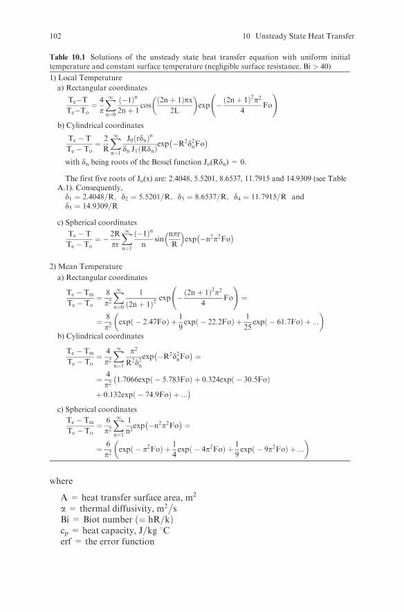
where
A = heat transfer surface area, m2
a = thermal diffusivity, m2�s
Bi = Biot number ¼ hR=kð Þcp = heat capacity, J=kg 8Cerf = the error function
Table 10.1 Solutions of the unsteady state heat transfer equation with uniform initialtemperature and constant surface temperature (negligible surface resistance, Bi > 40)
1) Local Temperature
a) Rectangular coordinates
Te�TTe�To
¼ 4
p
X1n¼0
�1ð Þn
2nþ 1cos
2nþ 1ð Þpx2L
� �exp � 2nþ 1ð Þ2p2
4Fo
!
b) Cylindrical coordinates
Te � T
Te � To¼ 2
R
X1n¼1
J0 rdnð Þn
dn J1 Rdnð Þexp �R2d2nFo
� �
with dn being roots of the Bessel function Jo(Rdn) = 0.
The first five roots of Jo(x) are: 2.4048, 5.5201, 8.6537, 11.7915 and 14.9309 (see TableA.1). Consequently,
d1 ¼ 2:4048=R; d2 ¼ 5:5201=R; d3 ¼ 8:6537=R; d4 ¼ 11:7915=R andd5 ¼ 14:9309=R
c) Spherical coordinates
Te � T
Te � To¼ � 2R
pr
X1n¼1
�1ð Þn
nsin
nprR
� �exp �n2p2Fo� �
2) Mean Temperature
a) Rectangular coordinates
Te � Tm
Te � To¼ 8
p2X1n¼0
1
2nþ 1ð Þ2exp � 2nþ 1ð Þ2p2
4Fo
!¼
¼ 8
p2expð � 2:47FoÞ þ 1
9expð � 22:2FoÞ þ 1
25expð � 61:7FoÞ þ :::
� �
b) Cylindrical coordinates
Te � Tm
Te � To¼ 4
p2X1n¼1
p2
R2d2nexp �R2d2nFo� �
¼
¼ 4
p2�1:7066expð � 5:783FoÞ þ 0:324expð � 30:5FoÞ
þ 0:132expð � 74:9FoÞ þ :::�
c) Spherical coordinates
Te � Tm
Te � To¼ 6
p2X1n¼1
1
n2exp �n2p2Fo� �
¼
¼ 6
p2expð � p2FoÞ þ 1
4expð � 4p2FoÞ þ 1
9expð � 9p2FoÞ þ :::
� �
102 10 Unsteady State Heat Transfer

erfc = the complementary error function defined as erfc = 1 - erfFo = Fourier number ¼ at
�L2
� �h = heat transfer coefficient, W
�m2 8C
Jo = Bessel function of the first kind of order zeroJ1 = Bessel function of the first kind of order onek = thermal conductivity, W
�m2�C
L = half thickness of the plate, mm = mass, kg
Table 10.3 Unsteady state heat transfer with negligible internal resistance ð0:1 < BiÞ
Te � T
Te � To¼ exp � hA
cpm
� �t
� �¼ expð � BiFoÞ
t ¼ mcphA
lnTe � To
Te � T
Table 10.2 Solutions of the unsteady state heat transfer equation for uniform initial tem-perature and both resistances, surface and internal, significant 0:15Bi540ð Þ1) Local Temperature
a) Rectangular coordinates
Te � T
Te � To¼X1n¼1
2Bi
d2n þ Bi2 þ Bi
cos xL dn� �
cos dnð Þexp �d2nFo� �
b) Cylindrical coordinates
Te � T
Te � To¼X1n¼1
2Bi
d2n þ Bi2Jo
rR dn� �Jo dnð Þ
exp �d2nFo� �
c) Spherical coordinates
Te � T
Te � To¼ R
r
X1n¼1
2 Bi
d2n þ Bi2 � Bi
sin rR dn� �
sin dnð Þexp �d2nFo� �
For the center of the sphere (r=0)
Te � T
Te � To¼X1n¼1
2 Bi
d2n þ Bi2 � Bi
dnsin dnð Þ
exp �d2nFo� �
with
dn roots of: d tand ¼ Bi
withdn roots of: d J1 dð Þ ¼ Bi Jo dð Þ
withdn roots of: d cotd ¼ 1� Bi
2) Mean Temperaturea) Rectangular coordinates
Te � Tm
Te � To¼X1n¼1
2Bi2
ðd2n þ Bi2 þ BiÞd2nexp �d2nFo� �
b) Cylindrical coordinates
Te � Tm
Te � To¼X1n¼1
4Bi2
d2n þ Bi2� �
d2nexp �d2nFo� �
c) Spherical coordinates
Te � Tm
Te � To¼X1n¼1
6 Bi2
d2n þ Bi2 � Bi� �
d2nexp �d2nFo� �
withdn roots of: d tand ¼ Bi
withdn roots of: d J1 dð Þ ¼ Bi Jo dð Þ
withdn roots of: d cotd ¼ 1� Bi
Theory 103
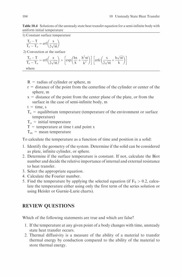
R = radius of cylinder or sphere, mr = distance of the point from the centerline of the cylinder or center of the
sphere, mx = distance of the point from the center plane of the plate, or from the
surface in the case of semi-infinite body, mt = time, sTe = equilibrium temperature (temperature of the environment or surface
temperature)To = initial temperatureT = temperature at time t and point xTm = mean temperature
To calculate the temperature as a function of time and position in a solid:
1. Identify the geometry of the system. Determine if the solid can be consideredas plate, infinite cylinder, or sphere.
2. Determine if the surface temperature is constant. If not, calculate the Biotnumber and decide the relative importance of internal and external resistanceto heat transfer.
3. Select the appropriate equation.4. Calculate the Fourier number.5. Find the temperature by applying the selected equation (if F0 > 0:2, calcu-
late the temperature either using only the first term of the series solution orusing Heisler or Gurnie-Lurie charts).
REVIEW QUESTIONS
Which of the following statements are true and which are false?
1. If the temperature at any given point of a body changes with time, unsteadystate heat transfer occurs.
2. Thermal diffusivity is a measure of the ability of a material to transferthermal energy by conduction compared to the ability of the material tostore thermal energy.
Table 10.4 Solutions of the unsteady state heat transfer equation for a semi-infinite bodywithuniform initial temperature
1) Constant surface temperature
Te � T
Te � To¼ erf
x
2ffiffiffiffiffiatp
� �
2) Convection at the surface
Te � T
Te � To¼ erf
x
2ffiffiffiffiffiatp
� �þ exp
hx
kþ h2at
k2
� � �erfc
x
2ffiffiffiffiffiatp þ h
ffiffiffiffiffiatp
k
� � �
where
104 10 Unsteady State Heat Transfer
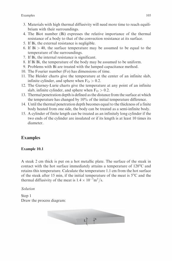
3. Materials with high thermal diffusivity will need more time to reach equili-brium with their surroundings.
4. The Biot number (Bi) expresses the relative importance of the thermalresistance of a body to that of the convection resistance at its surface.
5. If Bi, the external resistance is negligible.6. If Bi > 40, the surface temperature may be assumed to be equal to the
temperature of the surroundings.7. If Bi, the internal resistance is significant.8. If Bi Bi, the temperature of the body may be assumed to be uniform.9. Problems with Bi are treated with the lumped capacitance method.
10. The Fourier number (Fo) has dimensions of time.11. The Heisler charts give the temperature at the center of an infinite slab,
infinite cylinder, and sphere when FO > 0:2.12. The Gurney-Lurie charts give the temperature at any point of an infinite
slab, infinite cylinder, and sphere when FO > 0:2.13. Thermal penetration depth is defined as the distance from the surface at which
the temperature has changed by 10% of the initial temperature difference.14. Until the thermal penetration depth becomes equal to the thickness of a finite
body heated from one side, the body can be treated as a semi-infinite body.15. A cylinder of finite length can be treated as an infinitely long cylinder if the
two ends of the cylinder are insulated or if its length is at least 10 times itsdiameter.
Examples
Example 10.1
A steak 2 cm thick is put on a hot metallic plate. The surface of the steak incontact with the hot surface immediately attains a temperature of 120oC andretains this temperature. Calculate the temperature 1.1 cm from the hot surfaceof the steak after 15 min, if the initial temperature of the meat is 5oC and thethermal diffusivity of the meat is 1:4� 10�7m2
�s.
Solution
Step 1Draw the process diagram:
xL
Examples 105
Step 2Identify the geometry of the system.The shape of the steak is a plate heated from one side.
Step 3Examine the surface temperature.The surface temperature is constant.
Step 4Select the appropriate equation.The equation for a plate with uniform initial temperature and constant surfacetemperature is (Table 10.1):
Te � T
Te � To¼ 4
p
X1n¼0
�1ð Þn
2nþ 1cos
2nþ 1ð Þpx2L
� �exp � 2nþ 1ð Þ2p2
4Fo
!(10:1)
Step 5Calculate the Fourier number.Since the steak is heated only from one side, the characteristic dimension is thethickness of the steak, not the half thickness. Therefore:
Fo ¼ �t
L2¼ ð1:4� 10�7 m2=sÞð15� 60Þ
0:022 m2¼ 0:315
Step 6Calculate the temperatureSince FO > 0:2, only the first term of the sum in eqn (10.1) can be used withoutappreciable error. Alternatively, the solution can be read directly from aGurney-Lurie chart (see for example Ref. 3), which gives the dimensionlessratio Te � Tð Þ= Te � Toð Þ vs. the Fourier number. The temperature below iscalculated both ways:
i) From the equation:
Te � T
Te � To¼ 4
p
X1n¼0
�1ð Þn
2nþ 1cos
2nþ 1ð Þpx2L
� �exp � 2nþ 1ð Þ2p2
4Fo
!
� 4
p�1ð Þ0
2� 0þ 1cos
2� 0þ 1ð Þpx2L
� �exp � 2� 0þ 1ð Þ2p2
4Fo
!
¼ 4
pcos
px2L
� �exp � p2
4Fo
� �¼ 4
pcos
p� 0:009
2� 0:02
� �exp � p2
40:315
� �
¼ 0:445
Calculate the temperature as:
Te � T
Te � To¼ 120� T
120� 5¼ 0:445! T ¼ 68:8�C
106 10 Unsteady State Heat Transfer

ii) From the Gurnie-Lurie chart:
a) Find the value of Fo ¼ 0:315 on the x-axis of the Gurney-Lurie chart.b) Find the curve with k=hL ¼ 0 (constant surface temperature or
Bi!1) and x=L ¼ 0:009=0:02 ¼ 0:45.c) Read the dimensionless temperature on the y-axis as
Te � Tð Þ= Te � Toð Þ ¼ 0:45.d) Calculate the temperature as
Te � T
Te � To¼ 120� T
120� 5¼ 0:45! T ¼ 68:3�C
0.0
0.1
1.0
Fo
(Te–
T)/
(Te–
To) x/L = 0.45
k/hL = 0
0.80.60.40.20.0
Comment: The reading from the chart can only be approximate
Example 10.2
A hot dog 1.5 cm in diameter and 16 cm in length with 58C initial temperature is
immersed in boiling water. Calculate a) the temperature 3 mm under the surface
after 2 min, b) the temperature at the center after 2 min, c) the time necessary to
reach 818C at the center, d) the average temperature of the hot dog after 2 min,
and e) the heat that will be transferred to the hot dog during the 2min of boiling.
Assume that the thermal conductivity is 0:5W=m 8C, the density is 1050kg�m3,
the heat capacity is 3:35kJ=kg 8C, and the heat transfer coefficient at the surface
of the hot dog is 3000W�m2 8C.
Solution
Step 1Draw the process diagram:
Dr
R
L
Examples 107

Step 2Identify the geometry of the system.The hot dog has a cylindrical shape with L=D equal to:
L
D¼ 0:16m
0:015m¼ 10:7
Since L=D > 10, the hot dog can be treated as an infinite cylinder. The con-
tribution of heat transferred through the bases of the cylinder can be neglected.
Step 3Examine the surface temperature.Since the surface temperature is unknown, the Biot number must be calculated:
Bi ¼ hR
k¼
3000W=m2 oC� �
0:0075mð Þ0:5W=moC
¼ 45
Since Bi > 40 the external resistance to heat transfer is negligible. Therefore, it
can be assumed that the surface temperature will immediately reach the tem-
perature of the environment, 100oC.
Step 4Select the appropriate equation to use.The solution for constant surface tem-perature will be applied (Table 10.1):
Te � T
Te � To¼ 2
R
X1n¼1
J0 rdnð Þn
J1 Rdnð Þexp �R2d2nFo
� �(10:2)
Step 5Calculate the Fourier number.Calculate the thermal diffusivity first:
a ¼ k
rcp¼ 0:5W=moC
1050 kg=m3� �
3350 J=kgoCð Þ¼ 1:42� 10�7m2=s
Then:
Fo ¼ �t
R2¼ ð1:42� 10�7 m2=sÞð120 sÞ
0:00752 m2¼ 0:30
Since Fo > 0:2, only the first term of the series solution can be used without
appreciable error. Alternatively, the solution can be read directly from a chart
108 10 Unsteady State Heat Transfer

such as Gurney-Lurie or Heisler (see Fig A.3 and A.6 in the Appendix), which
gives the dimensionless ratio Te � Tð Þ= Te � Toð Þ vs. the Fourier number.
1) Calculate the temperature 3 mm under the surface.
i) From eqn (10.2) above:
Step 1Find the values of dn.
Since Fo > 0:2 the first term of the series solution is enough. However,
two terms will be used in this problem for demonstration purposes. Since
x ¼ Rdn and R = 0.0075, the values of dn will be (see Table A.1 in the
Appendix):
x dn
2.4048 320.6
5.5201 736.0
Step 2Substitute these values into eqn (10.2) and calculate T:
Te � T
Te � To¼ 2
R
X1n¼1
J0 rdnð Þn
dn J1 Rdnð Þexp �R2d2nFo
� �
� 2
0:0075
Jo 0:0045� 320:6ð Þ320:6� J1ð2:4048Þ
expð � 2:40482� �
0:30ð ÞÞ�
þ Jo 0:0045� 736ð Þ736� J1ð5:5201Þ
expð � 5:52012� �
0:30ð ÞÞ�
¼ 266:67Jo 1:4427ð Þ
320:6� J1 2:4048ð Þ exp �1:7349ð Þ�
þ Jo 3:312ð Þ736� J1 5:5201ð Þ exp �9:141ð Þ
�
¼ 266:670:5436
320:6� 0:5192exp �1:7349ð Þ
�
þ �0:3469736� �0:3403ð Þ exp �9:141ð Þ
�
¼ 266:67 5:76� 10�4 þ 1:48� 10�7� �
¼ 0:154
or
Te � T
Te � To¼ 100� T
100� 5¼ 0:154! T ¼ 85:48C
Examples 109

Comment: Notice that the 2nd term 1:48� 10�7� �
is much smaller than the first
term 5:76� 10�4� �
and could have been neglected.
ii) From the Gurney-Lurie chart for an infinite cylinder (see Fig A.3 in theAppendix):
Step 1Calculate the ratio r=Rwhich gives the position of the point (r is the distance ofthe point of interest from the axis of the cylinder):
r
R¼ 0:0045m
0:0075m¼ 0:6
Step 2Select the group of curves on the Gurney-Lurie chart that will be used based onthe k=hR value.
Since Bi > 40, the curves with k=hR ¼ 0 on the Gurney-Lurie chart can be
used.
Step 3On the Gurney-Lurie chart:
l Find the value of Fo ¼ 0:3 on the x-axisl Find the curve with k=hR ¼ 0 and r=R ¼ 0:6l Read the dimensionless temperature on the y-axis as
Te � Tð Þ= Te � Toð Þ ¼ 0:15l Calculate the temperature as
Te � T
Te � To¼ 100� T
100� 5¼ 0:15! T ¼ 85:8�C
0.01
0.10
1.00
0.0 0.2 0.4 0.6 0.8 1.0Fo
(Te-
T)/
(Te-
To) r/R = 0.6
k/hR = 0
2) Calculate the temperature at the center.
i) From the equation:As above but with r = 0 :
110 10 Unsteady State Heat Transfer
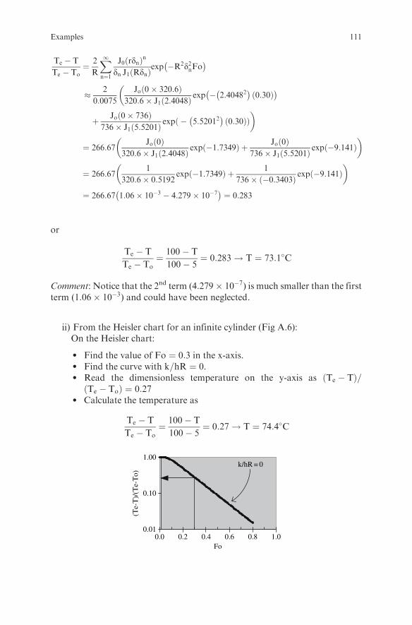
Te � T
Te � To¼ 2
R
X1n¼1
J0 rdnð Þn
dn J1 Rdnð Þexp �R2d2nFo
� �
� 2
0:0075
�Jo 0� 320:6ð Þ
320:6� J1ð2:4048Þexp � 2:40482
� �0:30ð Þ
� �
þ Jo 0� 736ð Þ736� J1ð5:5201Þ
expð � 5:52012� �
0:30ð ÞÞ�
¼ 266:67Jo 0ð Þ
320:6� J1 2:4048ð Þ exp �1:7349ð Þ þ Jo 0ð Þ736� J1 5:5201ð Þ exp �9:141ð Þ
� �
¼ 266:671
320:6� 0:5192exp �1:7349ð Þ þ 1
736� �0:3403ð Þ exp �9:141ð Þ� �
¼ 266:67 1:06� 10�3 � 4:279� 10�7� �
¼ 0:283
or
Te � T
Te � To¼ 100� T
100� 5¼ 0:283! T ¼ 73:1�C
Comment: Notice that the 2nd term (4:279� 10�7) is much smaller than the firstterm (1:06� 10�3) and could have been neglected.
ii) From the Heisler chart for an infinite cylinder (Fig A.6):On the Heisler chart:
l Find the value of Fo ¼ 0:3 in the x-axis.l Find the curve with k=hR ¼ 0.l Read the dimensionless temperature on the y-axis as Te � Tð Þ=
Te � Toð Þ ¼ 0:27l Calculate the temperature as
Te � T
Te � To¼ 100� T
100� 5¼ 0:27! T ¼ 74:4�C
0.01
0.10
1.00
0.0 0.2 0.4 0.6 0.8 1.0Fo
k/hR = 0
(Te-
T)/
(Te-
To)
Examples 111

3) Calculate the time necessary to reach 81oC at the center:Calculate the dimensionless temperature
Te � T
Te � To¼ 100� 81
100� 5¼ 0:2
On the Heisler chart:
l Find on the y-axis the value Te � Tð Þ= Te � Toð Þ ¼ 0:2l Find the curve k=hR ¼ 0.l Read the Fourier number on the x-axis as Fo ¼ 0:36.l Find the time from the Fourier number as:
t ¼ FoR2
�¼ 0:36
0:00752 m2
1:42� 10�7 m2=s¼ 143 s
0.01
0.10
1.00
Fo
k/hR = 0
0.0 0.2 0.4 0.6 0.8 1.0
(Te-
T)/
(Te-
To)
4) Calculate the average temperature.
Step 1Write the equation for the mean temperature of an infinite cylinder with
Bi > 40 ðTable 10:1Þ:
Te � Tm
Te � To¼ 4
p2X1n¼1
p2
R2d2nexp �R2d2nFo� �
¼ 4
p2
�1:7066 expð � 5:783FoÞ þ 0:324 expð � 30:5FoÞ
þ 0:132 expð � 74:9FoÞ þ :::�
Step 2Substitute values in the above equation and solve for Tm (since Fo > 0:2, thefirst term only is enough; in this example, three terms will be used for demon-stration purposes):
112 10 Unsteady State Heat Transfer

Te � Tm
Te � To¼ 4
p2
�1:7066 exp �5:783 � 0:3ð Þ þ 0:324 exp �30:5 � 0:3ð Þ
þ 0:132 exp �74:9� 0:3ð Þ þ :::::�
¼ 4
p20:3011þ 3:44� 10�5 þ 2:3� 10�11 þ :::� �
¼ 0:122
and
Tm ¼ Te � 0:122 Te � Toð Þ ¼ 100� 0:122 100� 5ð Þ ¼ 88:4 8C
Comment: Notice that the 2nd and 3rd terms of the sum are negligible compared
to the 1st term and they could have been omitted.
5) Calculate the heat transferred to the solid in 2 min.Because
qtqe¼ mcp Tm � Toð Þ
mcp Te � Toð Þ ¼Tm � To
Te � To¼ 1� Te � Tm
Te � To
the heat transferred to the hot dog in 2 min will be:
qt ¼ mcp Te � Toð Þ 1� Te � Tm
Te � To
� �
¼ Vrð Þcp Te � Toð Þ 1� Te � Tm
Te � To
� �
¼p 0:0152� �
m2
40:16mð Þ 1050
kg
m3
� � !3350
J
kg 8C
� �100� 5 oCð Þ 1� 0:122ð Þ
¼ 8296 J
Example 10.3
12mm� 16mm� 14mm rectangular fruit pieces are immersed in syrup. Calcu-
late the temperature at the center of a piece of fruit after 5 min if the initial
temperature of the fruit piece is 208C, the syrup temperature is 1008C, the heattransfer coefficient at the surface of the fruit piece is 83W
�m28C, and the physical
properties of the fruit piece are k ¼ 0:5W=m8C, cp ¼ 3:8kJ=kg8C, and
r ¼ 900kg�m3. Assume the fruit piece does not exchange matter with the syrup.
Solution
Step 1Draw the process diagram:
Examples 113
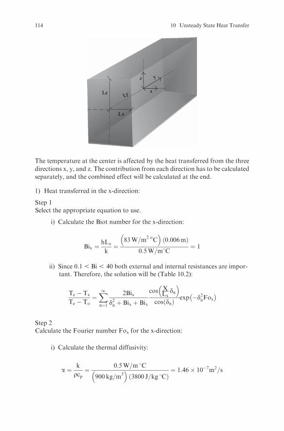
x
z y
Lx
LzLy
The temperature at the center is affected by the heat transferred from the three
directions x, y, and z. The contribution from each direction has to be calculated
separately, and the combined effect will be calculated at the end.
1) Heat transferred in the x-direction:
Step 1Select the appropriate equation to use.
i) Calculate the Biot number for the x-direction:
Bix ¼hLx
k¼
83W=m2 oC� �
0:006mð Þ0:5W=m8C
¼ 1
ii) Since 0:15Bi5 40 both external and internal resistances are impor-tant. Therefore, the solution will be (Table 10.2):
Te � Tx
Te � To¼X1n¼1
2Bix
d2n þ Bix þ Bix
cos XLx
dn� �
cos dnð Þexp �d2nFox� �
Step 2Calculate the Fourier number Fox for the x-direction:
i) Calculate the thermal diffusivity:
a ¼ k
rcp¼ 0:5W=m 8C
900 kg=m3� �
3800 J=kg 8Cð Þ¼ 1:46� 10�7m2=s
114 10 Unsteady State Heat Transfer
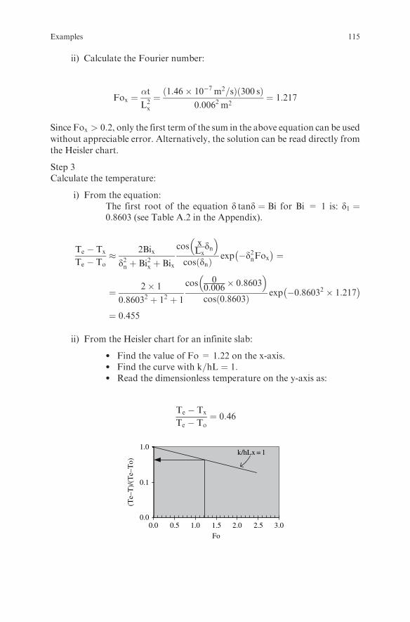
ii) Calculate the Fourier number:
Fox ¼�t
L2x
¼ ð1:46� 10�7 m2=sÞð300 sÞ0:0062 m2
¼ 1:217
Since Fox > 0:2, only the first term of the sum in the above equation can be used
without appreciable error. Alternatively, the solution can be read directly from
the Heisler chart.
Step 3Calculate the temperature:
i) From the equation:The first root of the equation d tand ¼ Bi for Bi = 1 is: d1 ¼0:8603 (see Table A.2 in the Appendix).
Te � Tx
Te � To� 2Bix
d2n þ Bi2x þ Bix
cos xLx
dn� �
cos dnð Þexp �d2nFox� �
¼
¼ 2� 1
0:86032 þ 12 þ 1
cos 00:006
� 0:8603� �cos 0:8603ð Þ exp �0:86032 � 1:217
� �
¼ 0:455
ii) From the Heisler chart for an infinite slab:
l Find the value of Fo = 1.22 on the x-axis.l Find the curve with k=hL ¼ 1:l Read the dimensionless temperature on the y-axis as:
Te � Tx
Te � To¼ 0:46
0.0
0.1
1.0
Fo
(Te–
T)/
(Te–
To)
k/hLx = 1
3.02.52.01.51.00.50.0
Examples 115

2) Heat transferred in the y-direction:
Step 1Select the appropriate equation to use.
i) Calculate the Biot number for the y-direction:
Biy ¼hLy
k¼
83W=m2 oC� �
0:008mð Þ0:5W=moC
¼ 1:328
ii) Since 0:1 < Bi < 40 both external and internal resistances are important.Therefore, the solution will be:
Te � Ty
Te � To¼X1n¼1
2Biy
d2n þ Biy þ Biy
cosy
Lydn
� �
cos dnð Þexp �d2nFoy� �
Step 2Calculate the Fourier number Foy for the y-direction:
Foy ¼�t
L2y
¼ ð1:46� 10�7 m2=sÞð300 sÞ0:0082 m2
¼ 0:684
Since Foy > 0:2, only the first term of the sum in the above equation can be usedwithout appreciable error. Alternatively, the solution can be read directly fromthe Heisler chart.
Step 3Calculate the temperature:
i) From the equation:The first root of the equation d tand ¼ Bi for Bi =1.328 is: d1 ¼ 0:9447(see Table A.2).
Te � Ty
Te � To� 2Biy
d2n þ Bi2y þ Biy
cosy
Lydn
� �
cos dnð Þexp �d2nFoy� �
¼ 2� 1:328
0:94472 þ 1:3282 þ 1:328
cos0
0:008� 0:9447
� �
cos 0:9447ð Þ
exp �0:94472 � 0:684� �
¼ 0:618
116 10 Unsteady State Heat Transfer
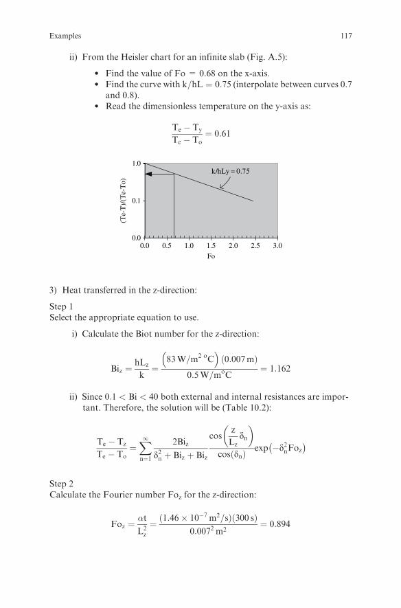
ii) From the Heisler chart for an infinite slab (Fig. A.5):
l Find the value of Fo = 0.68 on the x-axis.l Find the curve with k=hL ¼ 0:75 (interpolate between curves 0.7
and 0.8).l Read the dimensionless temperature on the y-axis as:
Te � Ty
Te � To¼ 0:61
0.0
0.1
1.0k/hLy = 0.75
Fo
0.0 0.5 1.0 1.5 2.0 2.5 3.0
(Te-
T)/
(Te-
To)
3) Heat transferred in the z-direction:
Step 1Select the appropriate equation to use.
i) Calculate the Biot number for the z-direction:
Biz ¼hLz
k¼
83W=m2 oC� �
0:007mð Þ0:5W=moC
¼ 1:162
ii) Since 0:1 < Bi < 40 both external and internal resistances are impor-tant. Therefore, the solution will be (Table 10.2):
Te � Tz
Te � To¼X1n¼1
2Biz
d2n þ Biz þ Biz
cosz
Lzdn
� �
cos dnð Þexp �d2nFoz� �
Step 2Calculate the Fourier number Foz for the z-direction:
Foz ¼�t
L2z
¼ ð1:46� 10�7 m2=sÞð300 sÞ0:0072 m2
¼ 0:894
Examples 117
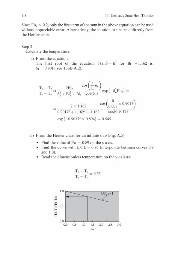
Since Foz > 0:2, only the first term of the sum in the above equation can be used
without appreciable error. Alternatively, the solution can be read directly from
the Heisler chart.
Step 3Calculate the temperature:
i) From the equation:The first root of the equation d tand ¼ Bi for Bi =1.162 is:
d1 ¼ 0:9017(see Table A.2):
Te � Tz
Te � To� 2Biz
d2n þ Bi2z þ Biz
cosz
Lzdn
� �
cos dnð Þexp �d2nFoz� �
¼
¼ 2� 1:162
0:90172 þ 1:1622 þ 1:162
cos0
0:007� 0:9017
� �
cos 0:9017ð Þ
exp �0:90172 � 0:894� �
¼ 0:545
ii) From the Heisler chart for an infinite slab (Fig. A.5):
l Find the value of Fo = 0.89 on the x-axis.l Find the curve with k=hL ¼ 0:86 (interpolate between curves 0.8
and 1.0).l Read the dimensionless temperature on the y-axis as:
Te � Tz
Te � To¼ 0:55
0.0
0.1
1.0
Fo
(Te–
T)/
(Te–
To)
k/hLx = 1
3.02.52.01.51.00.50.0
118 10 Unsteady State Heat Transfer

4) The combined effect of heat transferred in the x, y, and z directions is:
Te � Txyz
Te � To¼ Te � Tx
Te � To
� �Te � Ty
Te � To
� �Te � Tz
Te � To
� �
¼ 0:455� 0:618� 0:545 ¼ 0:153
and the temperature is:
100� Txyz
100� 20¼ 0:153! Txyz ¼ 87:8 8C
Example 10.4
Calculate how long it will take for the temperature on the non-heated surface
of the steak of Example 10.1 to increase by 1 % of the initial temperature
difference.
Solution
Step 1Identify the geometry of the system.As long as the temperature change on the cold surface of the steak is less than
1% of the initial temperature difference, the steak can be treated as a semi-
infinite body.
Step 2Examine the surface temperature.The surface temperature is constant at 120oC.
Step 3Select the appropriate equation.The equation for a semi-infinite body with uniform initial temperature and
constant surface temperature is (Table 10.4):
Te � T
Te � To¼ erf
x
2ffiffiffiffiffi�tp
� �
with
T� To
Te � To¼ 0:01
(since the accomplished temperature change is 1% )
Examples 119
or
Te � T
Te � To¼ 1� T� To
Te � To¼ 1� 0:01 ¼ 0:99
Therefore
0:99 ¼ erfx
2ffiffiffiffiffi�tp
� �
Step 4Find the erf of the argument x
�2ffiffiffiffiffi�tp
from an erf table (Table A.5).The argument has to be equal to 1.82 for the error function to be equal to 0.99.
Therefore
x
2ffiffiffiffiffi�tp ¼ 1:82
Step 5Solve for t:
t ¼x
3:64
� �2�
¼
0:02 m
3:64
� �2
1:4 � 10�7 m2=s¼ 215:6 s
Comment: The distance x where the temperature has increased by 1% of the
initial temperature difference is called the ‘‘thermal penetration depth.’’ As long
as the thermal penetration depth in a finite body is less than the thickness of the
body (or half the thickness of the body, in the case of heating from both sides),
the body can be treated as a semi-infinite body.
Example 10.5
Concentrated milk is sterilized in a can with 7.5 cm diameter and 9.5 cm
height. Calculate the time required to heat the milk from 458C to 1158Cgiven that: a) the can is in such a motion during heating that the milk
temperature is uniform inside the can, b) the can contains 410 g of milk, c)
the overall heat transfer coefficient between the heating medium and the milk
is 300W�m28C, d) the heating medium temperature is 1308C, and e) the mean
heat capacity of the milk over the temperature range of the heating process is
3650J=kg8C.
120 10 Unsteady State Heat Transfer

Solution
Since the milk temperature is uniform inside the can during heating, the internalresistance can be considered negligible. The solution for Bi < 0:1 can be applied(Table 10.3). Thus,
t ¼ mcphA
lnTe � To
Te � T¼
¼ 0:410 kgð Þ 3650 J=kgoCð Þ
300W=m28C� �
p 0:075mð Þ 0:095mð Þ þ 2 p 0:0752
4
� �m2
� � ln 130� 45
130� 115
¼ 277 s
Exercises
Exercise 10.1
Peas are blanched by immersion in hot water at 908C. Calculate the temperatureat the center of a pea after 3 min if the diameter of the pea is 8 mm, the initialtemperature of the pea is 208C, and the heat transfer coefficient at the surface ofthe pea is 100W
�m28C. Assume that the physical properties of the pea are
r ¼ 1050kg�m3, cp ¼ 3:7kJ=kg8C, k ¼ 0:5W=m8C.
Solution
Step 1State your assumptions.The pea can be assumed to be a sphere.
Step 2Select the equation for a sphere.
i) Calculate the Biot number:
Bi ¼ ::::::::::::::::::::::::::::::::::::::::::::::::::::::
Since 0:1 < Bi < 40, internal and external resistances are important.
ii) The equation to be used is:
Te � T
Te � To¼X1n¼1
2 Bi
d2n þ Bi2 � Bi
dnsin dnð Þ
exp �d2nFo� �
Exercises 121
Step 3Calculate the Fourier number:
� ¼ ::::::::::::::
:::::::::::::::::::::::::::::¼ :::::::::::::::
and
Fo ¼ ::::::::::::::::::::::::::::::::::::::::::::::::::::::
Since Fo > 0:2, only the first term of the sum in the above equation can be used
without appreciable error. Alternatively, the solution can be read directly from
the Heisler chart.
Step 4Calculate the temperature:
i) From the above equation:Substitute values in the above equation (d1 ¼ 1:432) and calculate thetemperature as
90� T
90� 20� ::::::::::::::::::::::::::::::::::::::::::::::::::::::::::::::::::::::::
T ¼ ::::::::::::::::::::::::::::::::::::::::::8C
ii) Also find the temperature from the Heisler chart for a sphere:
l Find the value of Fo on the x-axis.l Calculate k=hR and find the corresponding curve.
k
hR¼ :::::::::::::::::::::::::::::::::::
l Read the dimensionless temperature on the y-axis as:
Te � T
Te � To¼ ::::::::::::::::::::::::::
l Calculate the temperature as:
::::::::::::::::::::� T
:::::::::::::::::::::::::::::::::::
! T ¼ ::::::::::::::::::::::::
¼ :::::::
122 10 Unsteady State Heat Transfer

Fo(T
e-T
)/(T
e-T
o)
Exercise 10.2
A 211x300 can containing a meat product is heated in a retort. The initial
temperature of the can is 50oC, the heat transfer coefficient at the surface is
3000W�m28C, and the physical properties of the meat product are:
k ¼ 0:5W=m8C, cp ¼ 2:85kJ=m8C, and r ¼ 1100kg�m3. Calculate the tem-
perature at the geometric center of the can after 30 min if the steam temperature
in the retort is 130oC.
Solution
Step 1Determine the shape of the object.The shape of the can is a finite cylinder. The temperature at the center is affected
by the heat transferred from the cylindrical surface as well as from the flat bases
of the cylinder. The contribution from each direction has to be calculated
separately and the combined effect will be calculated at the end.
The dimensions of the can are:
Diameter ¼ 211
16inches ¼ 0:06826m;
Height ¼ 30
16inches ¼ 0:0762m
1) Calculate the heat transferred in the radial direction.
Step 1Select the appropriate equation:
i) Calculate the Biot number for the r-direction and determine the relativesignificance of external and internal resistances:
Bir ¼ :::::::::::::::::::::::::::::::::::::::::::::::::::::::::::
Exercises 123
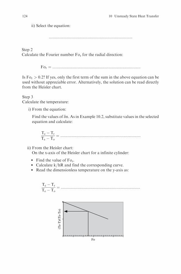
ii) Select the equation:
:::::::::::::::::::::::::::::::::::::::::::::::::::::::::::::::::::::::::::
Step 2Calculate the Fourier number For for the radial direction:
For ¼ :::::::::::::::::::::::::::::::::::::::::::::::::::::::::::::::::::::::::::::::
Is For > 0:2? If yes, only the first term of the sum in the above equation can beused without appreciable error. Alternatively, the solution can be read directlyfrom the Heisler chart.
Step 3Calculate the temperature:
i) From the equation:
Find the values of dn. As in Example 10.2, substitute values in the selectedequation and calculate:
Te � Tr
Te � To¼ ::::::::::::::::::::::::::::::::::::::::::::::::::::::::::::::::::::::::
ii) From the Heisler chart:On the x-axis of the Heisler chart for a infinite cylinder:
l Find the value of For.l Calculate k=hR and find the corresponding curve.l Read the dimensionless temperature on the y-axis as:
Te � Tr
Te � To¼ :::::::::::::::::::::::::::::::::::::::::::::::::::::::::::::::::::::::
Fo
(Te-
T)/
(Te-
To)
124 10 Unsteady State Heat Transfer
2) Calculate the heat transferred in the x-direction.
Step 1Select the appropriate equation:
i) Calculate the Biot number for the x-direction and determine the relativesignificance of external and internal resistances:
Bix ¼ ::::::::::::::::::::::::::::::::::::::::::::::::::::::::::::::::
ii) Select the equation:
:::::::::::::::::::::::::::::::::::::::::::::::::::::::::::::::::::::::::::::::::::::
Step 2Calculate the Fourier number Fox for the x-direction:
Fox ¼ :::::::::::::::::::::::::::::::::::::::::::::::::::::::::::::::::::::::::::::::
Is Fox > 0:2? If yes, only the first term of the sum in the above equation can be
used without appreciable error. Alternatively, the solution can be read directly
from the Heisler chart.
Step 3Calculate the temperature:
i) From the equation:Substitute values and calculate:
Te � Tx
Te � To¼ :::::::::::::::::::::::::::::::::::::::::::::::::::::::::::::::::::::::::::::::
ii) From the Heisler chart:On the x-axis of the Heisler chart for an infinite slab:
l Find the value of Fox.l Calculate k=hLx and find the corresponding curve.l Read the dimensionless temperature on the y-axis as:
Te � Tx
Te � To¼ ::::::::::::::::::::::::::
Exercises 125

Fo(T
e-T
)/(T
e-T
o)
3) Calculate the combined effect of the heat transferred through the cylind-rical surface and the heat transferred through the flat bases of the can:
Te � Trx
Te � To¼ Te � Tr
Te � To
� �Te � Tx
Te � To
� �¼ :::::::::::::::::::::::::::::::::::::::::::::::::
Calculate the temperature as:
130� Trx
:::::::::::::::::::::::::::::::
¼:::::::::::::::::::::::::! Trx ¼ ::::::::::::::::::::8C
Exercise 10.3
For the removal of field heat from fruits, hydrocooling is usually used. Calcu-late the time required to reduce the center temperature of a spherical fruit from
25oC to 5oC by immersion in cold water of 1oC if the diameter of the fruit is 6
cm, the heat transfer coefficient is 1000W�m2�C, and the physical properties of
the fruit are: k ¼ 0:4W=m�C, r ¼ 900kg�m3, cp ¼ 3:5kJ=kg�C.
SolutionSolve the problem using the Heisler chart for a sphere:
l Calculate the value of the dimensionless temperature:
Te � T
Te � To¼ :::::::::::::::::::::::::::::::::::
l Find the value of the dimensionless temperature on the y-axis of theHeisler chart:
l Calculate the value of k=hR and find the corresponding curve.
k
hR¼ :::::::::::::::::::::::::::::::
126 10 Unsteady State Heat Transfer
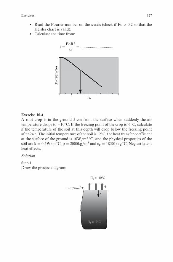
l Read the Fourier number on the x-axis (check if Fo > 0:2 so that theHeisler chart is valid).
l Calculate the time from:
t ¼FoR2
�¼ :::::::::::::::::::::::::::::::
Fo
(Te-
T)/
(Te-
To)
Exercise 10.4
A root crop is in the ground 5 cm from the surface when suddenly the air
temperature drops to �108C. If the freezing point of the crop is -18C, calculateif the temperature of the soil at this depth will drop below the freezing point
after 24 h. The initial temperature of the soil is 128C, the heat transfer coefficientat the surface of the ground is 10W
�m2 8C, and the physical properties of the
soil are k ¼ 0:5W=m 8C, r ¼ 2000kg�m3 and cp ¼ 1850J=kg 8C. Neglect latent
heat effects.
Solution
Step 1Draw the process diagram:
h = 10W/m2°C
x
T0 = 12°C
q
Te = –10°C
Exercises 127
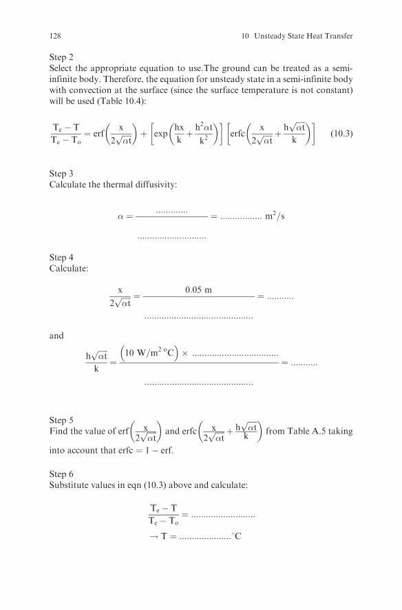
Step 2Select the appropriate equation to use.The ground can be treated as a semi-infinite body. Therefore, the equation for unsteady state in a semi-infinite bodywith convection at the surface (since the surface temperature is not constant)will be used (Table 10.4):
Te � T
Te � To¼ erf
x
2ffiffiffiffiffi�tp
� �þ exp
hx
kþ h2�t
k2
� � �erfc
x
2ffiffiffiffiffi�tp þ h
ffiffiffiffiffi�tp
k
� � �(10:3)
Step 3Calculate the thermal diffusivity:
� ¼ :::::::::::::
::::::::::::::::::::::::::::
¼ ::::::::::::::::: m2=s
Step 4Calculate:
x
2ffiffiffiffiffi�tp ¼ 0:05 m
::::::::::::::::::::::::::::::::::::::::::::
¼ :::::::::::
and
hffiffiffiffiffi�tp
k¼
10 W=m2 oC� �
� :::::::::::::::::::::::::::::::::::
::::::::::::::::::::::::::::::::::::::::::::
¼ :::::::::::
Step 5Find the value of erf x
2ffiffiffiffiffi�tp
� �and erfc x
2ffiffiffiffiffi�tp þ h
ffiffiffiffiffi�tpk
� �from Table A.5 taking
into account that erfc ¼ 1� erf.
Step 6Substitute values in eqn (10.3) above and calculate:
Te � T
Te � To¼ ::::::::::::::::::::::::::
! T ¼ :::::::::::::::::::::8C
128 10 Unsteady State Heat Transfer

Exercise 10.5
Calculate the temperature of 200 litres of glucose syrup heated in an agitated
jacketed vessel for 30 min if the initial temperature of the syrup is 308C, thetemperature of the steam in the jacket is 1208C, the density and the heat
capacity of the syrup are 1230kg�m3 and 3:35kJ=kg 8C respectively, the over-
all heat transfer coefficient between the heating medium and the syrup is
200W�m2 8C, and the inside surface area of the vessel in contact with the
syrup is 1.5 m2.
Solution
Step 1Select the appropriate equation to use.Since the syrup is agitated, its tempera-ture can be assumed to be uniform. Therefore the equation to use is:
::::::::::::::::::::::::::::::::::::::::::::::::::::::::::::::::::
Step 2Calculate the mass of the syrup:
m ¼ Vr ¼ ::::::::::::::::::::::::::::::::::::::::::::::::::::
Step 3Apply the selected equation:
Te � T
Te � To¼ :::::::::::::::::::::::::::::::::::::::::::::::::::::::::::::
! T ¼ :::::::::::::::::::::::8C
Exercises 129

Exercise 10.6
A thermocouple with 4 mm diameter and 2 cm length is immersed in milk whichis at 608C. How long it will take for the thermocouple to reach a temperature of59.5oC if the heat transfer coefficient at the surface of the thermocouple is200W
�m2 8C, the initial temperature of the thermocouple is 25oC, its mass
is 1 g, its heat capacity is 0:461kJ=kg�C, and its thermal conductivity is15W=m 8C. If the thermocouple were exposed to air of 60oC instead of milk,how long would it take to reach 59.5oC? Assume that the heat transfer coeffi-cient in this case is 20W
�m2 8C.
Solution
Step 1Select the appropriate equation:
i) Calculate the Biot number:
Bi ¼ :::::::::::::::::::::::::::::::::::::::::::::::::::::::::::::::::::::::::::::::::
ii) Determine the relative importance of internal and external resistance:
:::::::::::::::::::::::::::::::::::::::::::::::::::::::::::::::::::::::::::::::::::::::::
iii) Select and apply the appropriate equation:
:::::::::::::::::::::::::::::::::::::::::::::::::::::::::::::::::::::::::::::::::::::::::
Step 2For the case of air, repeat the calculations with h ¼ 20W
�m2�C.
Exercise 10.7
Solve Example 10.1 using the spreadsheet program Heat Transfer-NegligibleSurface Resistance.xls. Also solve the problem for the case in which thethickness of the steak is 3 cm and for the case in which the steak is heatedfrom both sides.
Solution
xLx
130 10 Unsteady State Heat Transfer
Step 1On the spreadsheet Heat Transfer-Negligible Surface Resistance.xls, go to thesheet ‘‘slab.’’Turn the ‘‘SWITCH’’ OFF (set the value in cell G1 equal to 0 and press
ENTER).
Step 2Insert the parameter values in the yellow cells using: half thickness in thex-direction Lx = 0.02 m (since the steak is heated from one side, Lx is equalto the thickness); half thickness in the y-direction and z-direction Ly = 1 m,Lz = 1 m (since the steak is considered as an infinite plate, use big numberson Ly and Lz to simulate the fact that heat transfer is significant only inthe x-direction); distance of the point from the coldest plane in the x-directionx ¼ 0:02� 0:011 ¼ 0:009m; distance in the z and y directions y = 0 and z = 0(since the steak is considered as an infinite plate); initial temperature To ¼ 5�C;surface temperature Te ¼ 120�C. Also insert the given values for the thermaldiffusivity.
Step 3Set the value of the time step to 15� 60 ¼ 900 s in cell F4.
Step 4Turn the ‘‘SWITCH’’ ON (set the value in cell G1 equal to 1 and pressENTER).
Step 5Read the value for the temperature of the point that lies 9 mm below the surfacein cell K20 (green cell).
Step 6Read the value for the mean temperature in cell K40 (green cell).
Step 7To see the effect of steak thickness, set Lx = 0.03. Repeat steps 2 to 6.
Step 8To see how the temperature of the point changes with time:
a) Turn the ‘‘SWITCH’’ OFF (set the value in cell G1 equal to 0 and pressENTER).
b) Set the value of the time step in cell F4 equal to 10 or some other smallvalue.
c) Turn the ‘‘SWITCH’’ ON (set the value in cell G1 equal to 1 and pressENTER).
d) Iterate by pressing F9 until the temperature in cell K20 reaches the valueyou want.
Exercises 131

Step 9To see howmuch faster the temperature at the same point would have increasedif the steak were heated from both sides, i.e., between the hot plates of a toaster:
xLx
a) Turn the ‘‘SWITCH’’ OFF (set the value in cell G1 equal to 0 and pressENTER).
b) Set the value of half thickness in the x-direction to Lx = 0.01 m.c) Set the value of the coordinates of the point to x= 0.001 m, y= 0, z = 0.d) Set the value of the time step equal to 10.e) Turn the ‘‘SWITCH’’ ON (set the value in cell G1 equal to 1 and press
ENTER).f) Iterate by pressing F9 until the same temperatures as in steps 5 and 6 are
reached.g) Read the time in cell F3.
Exercise 10.8
Solve Example 10.2 using the spreadsheet program Heat Transfer-Negligible
Surface Resistance.xls.
Solution
D
Lx x
r
Step 1On the spreadsheet Heat Transfer-Negligible Surface Resistance.xls, go to thesheet ‘‘cylinder.’’ Turn the ‘‘SWITCH’’ OFF (set the value in cell G1 equal to 0and press ENTER).
Step 2Insert the parameter values in the yellow cells using: diameter of the cylinderD = 0.015 m; half of the height of the cylinder Lx = 0.08 m; distance ofthe point from the center line in the direction of radius r = 0.0045 m
132 10 Unsteady State Heat Transfer
(point 3 mm from the surface); distance of the point from the center ofthe cylinder in the x direction x = 0; initial temperature To ¼ 5�C; surfacetemperature Te ¼ 100�C. Also insert the given values for the physical proper-ties and the heat transfer coefficient.
Step 3Read the Biot number for the r and x directions in cells B42 and C42
Step 4Set the value of the time step to 120 in cell F4.
Step 5Turn the ‘‘SWITCH’’ ON (set the value in cell G1 equal to 1 and press ENTER).
Step 6Read the value for the temperature of the point that lies 3 mm below the surfacein cell K20 (green cell).
Step 7Turn the ‘‘SWITCH’’ OFF (set the value in cell G1 equal to 0 and pressENTER).
Step 8Set the value of r = 0 and x = 0 (coordinates of the center of the cylinder).
Step 9Turn the ‘‘SWITCH’’ ON (set the value in cell G1 equal to 1 and pressENTER).
Step 10Read the value for the temperature of the center of the hot dog in cell K20(green cell).
Step 11Turn the ‘‘SWITCH’’ OFF (set the value in cell G1 equal to 0 and pressENTER).
Step 12Set the value of the time step to 0.5 in cell F4.
Step 13Turn the ‘‘SWITCH’’ ON (set the value in cell G1 equal to 1 and pressENTER).
Step 14Iterate by pressing F9 until the temperature in cell K20 is equal to 81oC. Readthe value of the time in cell F3.
Step 15Turn the ‘‘SWITCH’’ OFF (set the value in cell G1 equal to 0 and pressENTER).
Exercises 133
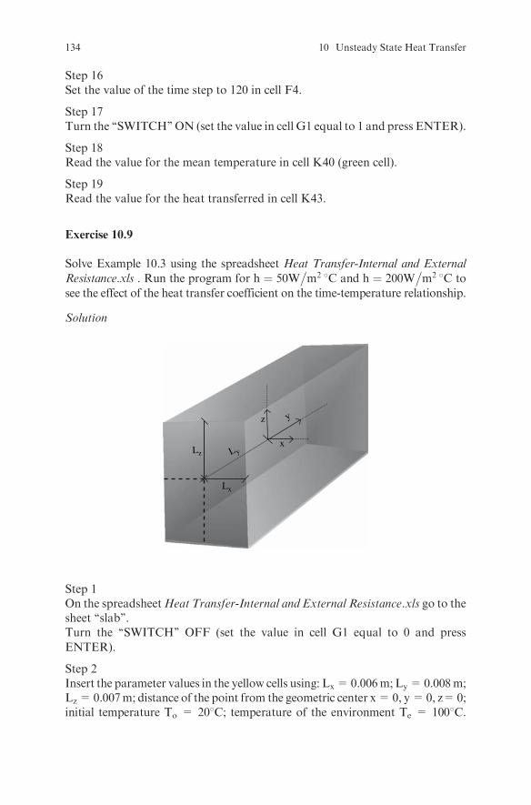
Step 16Set the value of the time step to 120 in cell F4.
Step 17Turn the ‘‘SWITCH’’ ON (set the value in cell G1 equal to 1 and press ENTER).
Step 18Read the value for the mean temperature in cell K40 (green cell).
Step 19Read the value for the heat transferred in cell K43.
Exercise 10.9
Solve Example 10.3 using the spreadsheet Heat Transfer-Internal and External
Resistance.xls . Run the program for h ¼ 50W�m2 8C and h ¼ 200W
�m2 8C to
see the effect of the heat transfer coefficient on the time-temperature relationship.
Solution
x
z y
Lx
Lz L y
Step 1On the spreadsheetHeat Transfer-Internal and External Resistance.xls go to thesheet ‘‘slab’’.Turn the ‘‘SWITCH’’ OFF (set the value in cell G1 equal to 0 and press
ENTER).
Step 2Insert the parameter values in the yellow cells using: Lx=0.006m; Ly=0.008m;Lz= 0.007m; distance of the point from the geometric center x=0, y=0, z=0;initial temperature To = 208C; temperature of the environment Te = 1008C.
134 10 Unsteady State Heat Transfer
Also insert the given values for the density, the heat capacity, the thermalconductivity, and the heat transfer coefficient.
Step 3Read the Biot numbers for the x, y, and z direction in cells B37, C37 and D37.Are they between 0.1 and 40?
Step 4Set the value of the time step to 5� 60 ¼ 300 in cell F4.
Step 5Turn the ‘‘SWITCH’’ ON (set the value in cell G1 equal to 1 and press ENTER).
Step 6Read the temperature for the center in cell K15 (green cell).
Step 7Read the mass average temperature in cell K30 (green cell).
Step 8To see how the temperature at the selected point changes with time turn the‘‘SWITCH’’ OFF (set the value in cell G1 equal to 0 and press ENTER).
Step 9Set the value of the time step equal to 10 (or some other small value) in cell F4.
Step 10Turn the ‘‘SWITCH’’ ON (set the value in cell G1 equal to 1 and press ENTER).
Step 11Iterate (by pressing F9) until the value of time in cell F3 (grey cell) reaches 300.
Step 12See the plot for the center temperature and mass average temperature vs. timeand the dimensionless temperature in the x-direction vs. Fourier number for thex-direction in the diagrams.
Step 13Change the value of h and the corresponding values of di. Run the program andsee the temperature at the center after 5 min.
Step 14Make the necessary changes in the spreadsheet to plot the dimensionless non-accomplished temperature change for the y and z directions.
Exercise 10.10
For the removal of field heat from certain fruits, hydrocooling, forced air
cooling and room cooling have been proposed. Calculate and plot the tempera-
ture change at the center of the fruit vs. the time for the three methods. Assume
Exercises 135

that the fruit is spherical; its initial temperature is 25oC; the cold water and the
air temperature are 1oC; the diameter of the fruit is 6 cm; the heat transfer
coefficient is 1000W�m2�C in the case of hydrocooling, 20W
�m2 8C in the case
of forced air cooling, and 5W�m2�C in the case of room cooling; and
the physical properties of the fruit are: k ¼ 0:4W=m 8C, r ¼ 900kg�m3,
cp ¼ 3:5kJ=kg 8C.
Solution
r
D
Step 1Calculate the Biot number in all cases.
Step 2Select the spreadsheet Heat Transfer-Negligible Surface Resistance.xls or HeatTransfer- Internal and External Resistance.xls depending on the value of Biotnumber.
Step 3Follow the instructions and run the program for a sphere.
Step 4Run the program using a small time increment, e.g., 10 s.
Exercise 10.11
The product development department in a food plant is interested in knowing
what shape they should give to a new product for a faster temperature change at
the center of the product from 20oC to 90oC. Should the shape be a cube
50mm� 50mm� 50mm, a cylinder with diameter 62.035 mm and length41.36 mm, or a sphere with diameter 62.035 mm? All these shapes will have
136 10 Unsteady State Heat Transfer

the same volume and the samemass. The heating medium is steam at 100oC; the
heat transfer coefficient in all cases is 2000W�m2�C; and the density, the heat
capacity, and the thermal conductivity of the product are 900kg�m3,
3200J=kg�C, and 0:5W=m�C respectively. Determine which shape will give a
faster temperature change at the center.
Solution
Step 1Calculate the Biot number in all cases.
Step 2Select the spreadsheet Heat Transfer-Negligible Surface Resistance.xls or HeatTransfer- Internal and External Resistance.xls depending on the value of theBiot number.
Step 3Follow the instructions and run the program for a cube, a cylinder, and asphere.
Step 4Find the time necessary in each case for Tlocal to reach 90oC.
Exercise 10.12
Understand how the spreadsheet program Heat Transfer-Negligible Surface
Resistance.xls calculates and plots the temperature change of a sphere with
time. Modify the program to plot the temperature distribution with the radius
of the sphere for a certain time.
Exercise 10.13
Understand how the spreadsheet programHeat Transfer-Internal and External
Resistance.xls calculates and plots the temperature change of a cylinder with
time. Modify the program to plot qt�qevs:Fo
0:5 for a certain Biot number value
for an infinite cylinder.
Exercise 10.14
a) Solve Exercise 10.4 using the spreadsheet program Semi-Infinite body 1.xls.
b) Plot the temperature profile for the depth 0-5 cm after 12 h and 24 h. c) What
is the minimum depth at which the temperature does not change after 12 h?
d) Observe how the temperature changes with time at the depth of 1 cm, 3 cm,
and 5 cm for the first 24 hours.
Exercises 137
Solution
Step 1In the sheet ‘‘T vs. x’’, follow the instructions, run the program for Time ¼24� 3600 ¼ 86400 s and read the temperature in cell F16 when the distance incell F3 is equal to 0.05 m. Observe the temperature profile in the plot.
Step 2Set the time equal to 12� 3600 ¼ 43200 s in cell B29, follow the instructions,run the program, and observe the temperature profile in the plot.
Step 3Continue running the program until the temperature in cell F16 is equal to12oC. Read the depth in cell F3.
Step 4In the sheet ‘‘T vs. t’’, follow the instructions, run the program for Distancex = 0.01 m until Time = 86400 s in cell F3. Observe the temperature profile inthe plot. Rerun the program for x = 0.03 m and x = 0.05 m following theinstructions.
Exercise 10.15
Use the spreadsheet program Semi-Infinite body 2.xls, to study how the tem-perature in a semi-infinite body changes with time when a) the temperature atthe surface is constant, and b) the temperature at the surface is not constant butis affected by convection. Find the value of h
ffiffiffiffiffi�tp �
k for which the solution forboth cases is approximately the same.
Solution
Step 1In the sheet ‘‘Convection at the surface’’, follow the instructions and run theprogram for various values of h
ffiffiffiffiffi�tp �
k in cell B41.
Step 2Read the temperature in cell H16.
Step 3For the case in which the temperature at the surface is constant, run the sheet‘‘Constant surface temperature.’’
Step 4Observe the temperature change in the Temperature vs. Time plot. Observe thedifference between the two solutions for low values of h
ffiffiffiffiffi�tp �
k. Which is thecorrect one?
Step 5Observe the plot of accomplished temperature change T�To
Te�Tovs. x
2ffiffiffiffiffi�tp .
Compare it with the respective plot in your textbook, e.g., Ref 3, 4, 5.
138 10 Unsteady State Heat Transfer
Exercise 10.16
Using the spreadsheet program Semi-Infinite body 3.xls, calculate the time
necessary for the thermal penetration depth to reach the non-heated surface
of the steak of Example 10.1. If the temperature of the hotplate changes to
150oC, does the time necessary for the thermal penetration depth to reach the
non-heated surface of the steak change? Is the temperature at x = 0.02 m the
same as in the case of 120oC at the time the thermal penetration depth is equal to
the thickness of the steak?
Solution
Step 1In the sheet ‘‘Calculations,’’ follow the instructions and insert the parametervalues. For the heat transfer coefficient use a high value, e.g., 3000W
�m2�C in
cell B39 (assume a negligible conduct resistance).
Step 2Run the program until Time in cell F4 remains constant. Read the required timein cell G16.
Step 3Observe the temperature change in the Temperature vs. Distance plot.
Step 4Use a hotplate temperature in cell B31 of 150oC. Rerun the program until Timein cell G16 remains constant. Read the required time in cell G16.
Step 5Read the temperature in cell G18 when x=0.02 in cell G17. Compare this valuewith the corresponding temperature when the hot plate temperature is 120oC.
Exercise 10.17
In the ‘‘hot-break’’ process, whole tomatoes are heated with live steam to
inactivate the pectin methylesterase enzyme before crushing and extraction,
thereby yielding high viscosity products. Calculate the time necessary to heat
the center of a tomato 6 cm in diameter to 50oC using 100oC steam if the initial
temperature of the tomato is 20oC and the density, the heat capacity, and the
thermal conductivity for tomatoes are 1130kg�m3, 3:98kJ=kg�C, and
0:5W=m�C respectively. Find the time necessary for the mass average tempera-
ture to reach a value of 82 oC.
Solution
Use the spreadsheet Heat Transfer-Negligible Surface Resistance.xls to solve
the problem. Write the necessary assumptions.
Exercises 139

Exercise 10.18
A potato 5 cm in diameter is immersed in boiling water. Calculate the requiredtime for the temperature at the center of the potato to reach 59oC, the onset ofstarch gelatinization, if the initial temperature of the potato is 21oC and thedensity, the heat capacity and the thermal conductivity for potatoes are1120kg
�m3, 3:7kJ=kg 8C and 0:55W
�m 8C respectively. Find the mass average
temperature of the potato when the center temperature is 59oC. Study the effectof diameter on the required time. Is it proportional to D or to D2?
Solution
Use the spreadsheet Heat Transfer-Negligible Surface Resistance.xls to solvethe problem. Write the necessary assumptions.
140 10 Unsteady State Heat Transfer
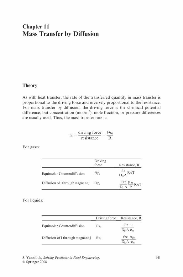
Chapter 11
Mass Transfer by Diffusion
Theory
As with heat transfer, the rate of the transferred quantity in mass transfer is
proportional to the driving force and inversely proportional to the resistance.
For mass transfer by diffusion, the driving force is the chemical potential
difference; but concentration (mol/m3), mole fraction, or pressure differences
are usually used. Thus, the mass transfer rate is:
ni ¼driving force
resistance¼ �ci
R
For gases:
Drivingforce Resistance, R
Equimolar Counterdiffusion �pi�z
Di jARGT
Diffusion of i through stagnant j �pi�z
Di jA
pjMP
RGT
For liquids:
Driving force Resistance, R
Equimolar Counterdiffusion �xi �z
Di jA
1
cm
Diffusion of i through stagnant j �xi �z
Di jA
xjMcm
S. Yanniotis, Solving Problems in Food Engineering.� Springer 2008
141

For solids:
Mass transfer rate
For a single wall ni¼�ciR
For a composite wall ni¼�ciPR
Resistance, R Surface area, A
Flat wall�z
DAA
Cylindrical wall �r
DALMALM¼
A1�A2
ln A1=A2
Spherical wall�r
DAGAG¼
ffiffiffiffiffiffiffiffiffiffiffiffiA1A2
p
Flat packaging films:
Resistance, R Surface area, A
For gases 22414� z
PMAA
For water vapor� z
PMWV�A A
where
A = surface area perpendicular to the direction of transfer, m2
ALM = logarithmic mean of surface area A1 and A2, m2
AG = geometric mean of surface area A1 and A2, m2
ci = concentration of i, mol/m3
cm = mean concentration of i and j, mol/m3
D = diffusion coefficient, m2/sDij = diffusion coefficient of i in j, m2/sni= mass transfer flux, rate, mol/sP = total pressure, Papi = partial pressure of i, PapjM = logarithmic mean pressure difference of j, PaPM = gas permeability, cm3 cm/s cm2 atmPM WV = water vapor permeability, g cm/s cm2 PaRG = ideal gas constant, m3 Pa/mol KT = temperature, K
142 11 Mass Transfer by Diffusion
xi = mol fraction of ixjM = logarithmic mean mol fraction of j�z and �r = wall thickness, m
Review Questions
Which of the following statements are true and which are false?
1. Fick’s 1st law refers to mass transfer by diffusion at steady state.2. Molecular diffusion is a phenomenon analogous to heat transfer by
conduction.3. The resistance to mass transfer increases linearly with diffusivity.4. Mass diffusivity has the same units as thermal diffusivity and kinematic
viscosity.5. Diffusivity in gasses is about 10000 times higher than in liquids.6. Diffusivity does not vary with temperature.7. Diffusivity in solids may vary with concentration.8. The driving force for mass transfer by molecular diffusion is the difference
in chemical potential.9. There is bulk flow in equimolar counterdiffusion.
10. In equimolar counterdiffusion Ni=�Nj, where Ni and Nj are the fluxes ofgas i and gas j with respect to a fixed position.
11. There is no bulk flow in the case of diffusion of gas i through stagnantnondiffusing gas j.
12. For the same driving force, the flux Ni in equimolar counterdiffusion issmaller than Ni in diffusion of i through stagnant nondiffusing j due to thebulk motion of i.
13. When concentrations are dilute, the bulk flow may be negligible.14. Permeability refers to the diffusion of a gas in a solid and is used extensively
in calculating mass transfer in packaging materials.15. Permeability is equal to the product of the diffusion coefficient and the
solubility of the gas in the solid.16. The difference in partial pressure inside and outside the
packaging material is being used as the driving force for mass transfercalculations.
17. Permeability decreases as the temperature increases.18. Layers of different materials may be combined in laminates to give a
composite material with good barrier properties for water vapor, gasses,and light.
19. Polyethylene is a good water vapor barrier and serves as an adhesive to thenext layer.
20. Aluminum foil is a good gas barrier
Review Questions 143
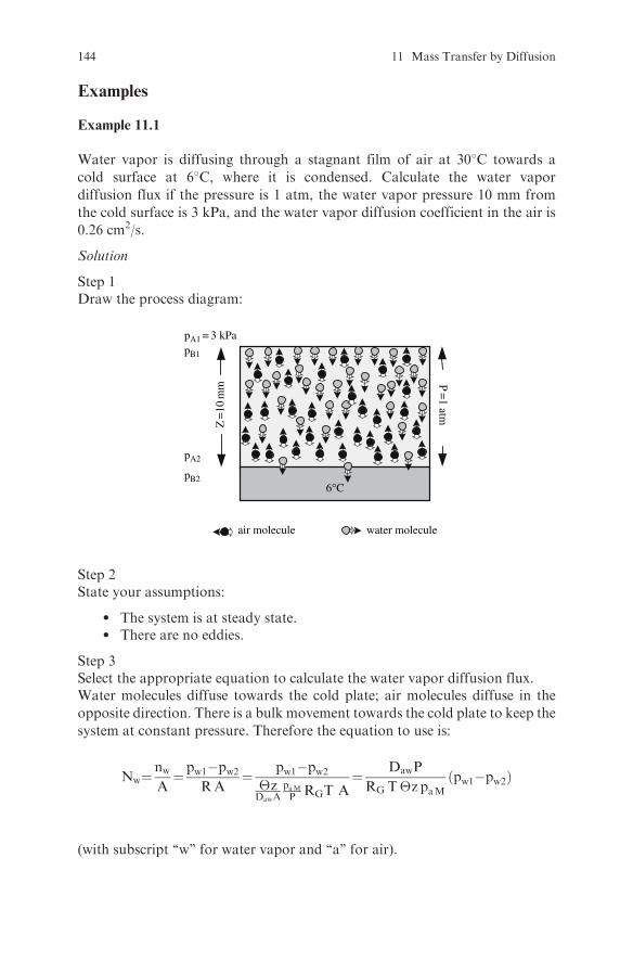
Examples
Example 11.1
Water vapor is diffusing through a stagnant film of air at 308C towards a
cold surface at 68C, where it is condensed. Calculate the water vapor
diffusion flux if the pressure is 1 atm, the water vapor pressure 10 mm from
the cold surface is 3 kPa, and the water vapor diffusion coefficient in the air is
0.26 cm2/s.
Solution
Step 1Draw the process diagram:
pA1 = 3 kPapB1
pA2
pB26°C
air molecule
Z =
10 m
m P =
1 atm
water molecule
Step 2State your assumptions:
l The system is at steady state.l There are no eddies.
Step 3Select the appropriate equation to calculate the water vapor diffusion flux.Water molecules diffuse towards the cold plate; air molecules diffuse in the
opposite direction. There is a bulk movement towards the cold plate to keep the
system at constant pressure. Therefore the equation to use is:
Nw¼nwA¼ pw1�pw2
RA¼ pw1�pw2
�zDawA
paMP RGT A
¼ DawP
RG T�z paMpw1�pw2ð Þ
(with subscript ‘‘w’’ for water vapor and ‘‘a’’ for air).
144 11 Mass Transfer by Diffusion
Step 4Find the values of partial pressure to use in the above equation:
i) The water vapor partial pressure at the interphase at 68C is
pw2¼ 0:935 kPaðfrom steam tablesÞ:
ii) The partial pressure of air is
pa1¼ 101325� 3000 ¼ 98325 Pa
and
pa2¼ 101325� 935 ¼ 100390 Pa
paM¼pa1�pa2lnpa1pa2
¼ 98325 � 100390
ln98325
100390
¼ 99353:9 Pa
Comment: The arithmetic mean instead of the log mean could have been used
with very little error, since pa1 and pa2 values differ from one another by a small
percentage.
Step 5Substitute values and calculate the water vapor diffusion flux:
Nw¼DawP
RT z paMpw1 � pw2ð Þ¼
¼0:26x10�4 m2=s� �
101325 Pað Þ8314:34m3Pa=kmol Kð Þ 303Kð Þ 0:01mð Þ 99353:9 Pað Þ 3000� 935ð ÞPa ¼
¼ 2:17x10�6 kmol=s m2
Example 11.2
A food product is sealed in a flexible laminated package with 0.1 m2
surface area that is made of a polyethylene film layer 0.1 mm thick and a
polyamide film layer 0.1 mm thick. The package is stored at 218C and 75%
relative humidity. Calculate the transfer rate of oxygen and water
Examples 145

vapor through the film at steady state if the partial pressure of O2 inside the
package is 0.01 atm, that outside the package is 0.21 atm, and the
water activity of the product inside the package is 0.3. The permeability
(PM) of polyethylene and polyamide to O2 are 2280�10�11 and 5�10�11 cm3/
(s cm2 atm /cm) respectively, and the water vapor transmission rate (WVTR)
for these materials measured at 37.88C using 90% RH water vapor source
and 0% RH desiccant sink are 6�10�11 and 37�10�11 g/(s cm2 /cm)
respectively.
Solution
Step 1State your assumptions:
l The convective resistance to mass transfer on the two sides of thepackage are negligible compared to the diffusion resistance of thefilm.
l The WVTR at 218C does not differ appreciably from that at 37.88C.
Step 2Calculate the diffusion rate of oxygen:
i) Select the equation to use:
nO2¼
�pO2PR
ii) Substitute values and calculate the diffusion rate:
XR ¼ Rpolyethylene þRpolyamid ¼
¼ 22414�zpolyeth:A PMpolyeth:
þ 22414 �zpolyam:APMpolyam:
¼ 22414
A
�zpolyeth:PMpolyeth:
þ �zpolyam:PM polyam:
� �¼
¼22414 cm3=mol� �
1000 cm2ð Þ0:01 cmð Þ
2280� 10�11cm3 cm=s cm2 atm� �
þ 0:01 cmð Þ5� 10�11cm3 cm=s cm2 atm� �
!¼
¼ 9:83� 106 þ 4:48� 109 ¼ 4:49� 109 atm s=mol
nO2¼
�pO2PR¼ 0:21� 0:01 atm
4:49� 109 atm s=mol¼ 4:45� 10�11 mol=s
146 11 Mass Transfer by Diffusion

Step 3Calculate the diffusion rate of water vapor.
i) Select the equation to use:
nw ¼�pwP
R
with pwthe water vapor difference between the inside and the outside of
the package and
R ¼ �z
PMWV A
ii) Find the water vapor pressure inside and outside the package.The water vapor pressure pw at 218C is 2487 Pa (from steam tables).
The water vapor partial pressure outside the package for 75% relative
humidity is:
pwo¼75
1002487 ¼ 1865:3 Pa
Thewater vapor partial pressure inside the package forwater activity 0.3 is:
pw i ¼ 0:3 x 2487 ¼ 746:1 Pa
iii) Calculate the water vapor permeability.Water vapor permeability for polyethylene can be calculated from the
Water Vapor Transmission Rate as:
PMWVpolyethylene ¼WVTRpolyeth:
�p¼ 6� 10�11g cm=s cm2
0:90� 6586� 0 Pa
¼ 1:01� 10�14g cm=s cm2 Pa
Similarly for polyamide:
PMWVpolyamid ¼WVTRpolyeth:
�P¼ 37� 10�11g cm=s cm2
0:90� 6586� 0 Pa
¼ 6:24� 10�14g cm=s cm2 Pa
Examples 147

iv) Calculate the total resistance to water vapor transfer for the laminate:
XR ¼ Rpolyet h y l e ne þRpolyamid ¼
� zpolyeth:PMWV polyeth:A
þ �zpolyamid
PMWVpolyamidA¼
¼ 0:01 cm
1:01� 10�14g cm=s cm2 Pa� �
1000 cm2ð Þ
þ 0:01 cm
6:24� 10�14g cm=s cm2 Pa� �
1000 cm2ð Þ¼
¼ 9:90� 108 þ 1:60� 108 ¼ 1:15� 109 Pa s=g
v) Calculate the water vapor transfer rate:
nw ¼�pwP
R¼ 1865:3� 746:1 Pa
1:15� 109 Pa s =g¼ 9:73� 10�7 g=s
Comment: Notice that the polyethylene film layer contributes the main resis-tance to water vapor transfer (86.1%), while polyamide contributes the mainresistance to oxygen transfer (99.8%).
Exercises
Exercise 11.1
Water evaporates from the flat surface of the leaf of a vegetable and isdiffusing away through a stagnant layer of air. The total pressure is 101325Pa and the temperature is 248C. Calculate the evaporation rate in g/s underthe following conditions: water activity (aw) of the leaf surface is 0.98, partialwater vapor pressure 5 mm away from the surface of the leaf is 2100 Pa,surface area of the leaf is 50 cm2. The diffusion coefficient of water vapor inair is 2.6�10�5 m2/s.
Solution
Step 1State your assumptions:
The time interval the calculations are based on is small so that the watervapor pressure at the surface of the leaf is constant and the system is atsteady state.
148 11 Mass Transfer by Diffusion
Step 2Select the equation to use:
Since water vapor diffuses through a stagnant layer of air, the equation to be
used is:
Nw¼ :::::::::::::::::::::::::::::::::::::::::::::::::::
Step 3Find the water vapor pressure pw at 248C from the steam tables: ....................Calculate the partial water vapor pressure pw1 at the surface of the leaf as:
pw1 ¼ aw: pw ¼ :::::::::::::::::::::::::::::::::::::
Step 4Calculate the partial pressure of air:
pa1 ¼ P� pw1 ¼ :::::::::::::::::::::::::::::::::::::::::::::::
pa2 ¼ ::::::::::::::::::::::::::::::::::::::::::::::::::::::::::::::::
paM ¼ :::::::::::::::::::::::::::::::::::::::::::::::::::::::::::::::::
Step 5Calculate the mass transfer flux:
Nw ¼ ::::::::::::::::::::::::::::::::::::::::::::::::::::::::::::::::::::::::::::::::::::::::kmol=s m2
Step 6Calculate the evaporation rate:
nw ¼ ::::::::::::::::::::::::::::::::::::::::::::::::::::::::::::::::::::::::::::::::::::::::::::g=s
Exercise 11.2
An aroma compound is encapsulated in a nonporous spherical particle made of
a homogenous biopolymer film. Calculate the aroma release rate if the particle
diameter is 1 mm, the film thickness is 0.1 mm, the concentration of the aroma
compound is 0.1 g/cm3 and 0.01g/cm3 on the inside and outside surface of the
particle respectively, and the diffusion coefficient of the aroma compound in the
film is 1�10�12 m2/s.
Exercises 149
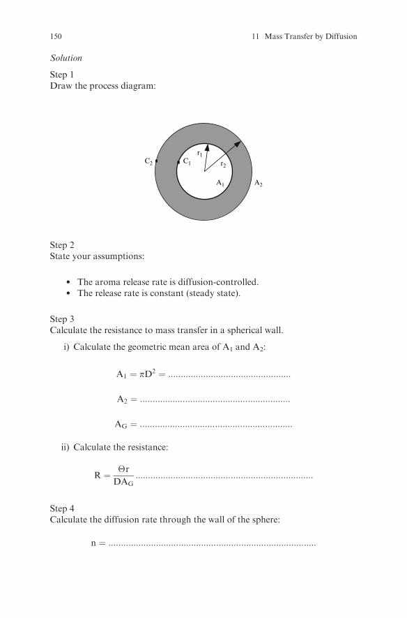
Solution
Step 1Draw the process diagram:
r2
r1
A1 A2
C1C2
Step 2State your assumptions:
l The aroma release rate is diffusion-controlled.l The release rate is constant (steady state).
Step 3Calculate the resistance to mass transfer in a spherical wall.
i) Calculate the geometric mean area of A1 and A2:
A1 ¼ pD2 ¼ :::::::::::::::::::::::::::::::::::::::::::::::::
A2 ¼ ::::::::::::::::::::::::::::::::::::::::::::::::::::::::::::
AG ¼ :::::::::::::::::::::::::::::::::::::::::::::::::::::::::::::
ii) Calculate the resistance:
R ¼ �r
DAG:::::::::::::::::::::::::::::::::::::::::::::::::::::::::::::::::::::::
Step 4Calculate the diffusion rate through the wall of the sphere:
n ¼ :::::::::::::::::::::::::::::::::::::::::::::::::::::::::::::::::::::::::::::::::::
150 11 Mass Transfer by Diffusion
Exercise 11.3
The solubility and the diffusivity of O2 in polyvinyl chloride are 3.84x10�4 cm3
O2 at STP/cmHg.cm3 solid and 1.18x10�12 m2/s respectively. Calculate thepermeability of polyvinyl chloride to O2.
Solution
The permeability is the product of solubility and diffusivity. Therefore:
PM ¼ S:D ¼:::::::::::::::::::::::::::::::::::::::::::::::::::::::::::::::::::::::::::::::::::::: cm3 cm
s cm2Pa
Exercise 11.4
A supplier of frozen hamburger patties is thinking of packaging them in 0.1 mmthick polypropylene film. The permeability of polypropylene to O2 and watervapor is 1x10�8 cm3/(s cm2 atm /cm) and 8x10�15 g/(s cm2 Pa/cm) respectively.The partial pressure of O2 is 0 atm and that of water vapor is 0.12 Pa inside thepackage, while outside the package the partial pressure of O2 is 0.21 atm andthat of water vapor is 0.04 Pa. Calculate how much oxygen and how muchwater vapor will pass through the polypropylene film of 600 cm2 surface area inone week.
Solution
Step 1Sate your assumptions:
l The convective resistance to mass transfer on the two sides of thepackage is negligible compared to the diffusion resistance of the film.
l ..............................................................................................................
Step 2Calculate the transfer rate of O2.
i) Calculate the resistance:
R ¼ ::::::::::::::::::::::::::::::::::::::::::::::::::::::::::::::::::::::::::::::::
ii) Calculate the transfer rate of oxygen:
nO2¼ :::::::::::::::::::::::::::::::::::::::::::::::::::::::::::::::::::::::::::::::mol=s
Step 3Calculate the total amount of O2 that will diffuse into the package in one week:
mO2¼ ::::::::::::::::::::::::::::::::::::::::::::::::::::::::::::::::::::::::::::::::::: g
Exercises 151

Step 4Calculate the transfer rate of water vapor.
i) Calculate the resistance:
R ¼ :::::::::::::::::::::::::::::::::::::::::::::::::::::::::::::::::::::::::::::::::
ii) Calculate the transfer rate of water vapor:
nw ¼ ::::::::::::::::::::::::::::::::::::::::::::::::::::::::::::::::::::::::::::g=s
Step 5Calculate the total amount of water vapor that will diffuse out of the package inone week:
mw ¼ ::::::::::::::::::::::::::::::::::::::::::::::::::::::::::::::::::::::::::::::: g
Exercise 11.5
Meat is packaged in a plastic disk coveredwith PVC film. Calculate the requiredthickness of the film so that 1�10�4 mol of oxygen enters the package throughthe film in 24 hours. The permeability of PVC to oxygen is 456�10�11 cm3/(s cm2 atm /cm), the surface area of the film is 300 cm2, and the partial pressureof oxygen inside and outside the package is 0 atm and 0.21 atm respectively.
Solution
Step 1State your assumptions:..........................................................................................................................
Step 2Calculate the mass transfer rate in mol/s:
nO2¼ :::::::::::::::::::::::::::::::::::::::::::::::::::::::::::::::::::::
Step 3Calculate the required resistance:
R ¼ ::::::::::::::::::::::::::::::::::::::::::::::::::::::::::::::::
Step 4Calculate the required thickness of the film
�z ¼ PM A
22414R ¼ :::::::::::::::::::::::::::::::::::::::::::::::::::::::::::::::::
152 11 Mass Transfer by Diffusion
Exercise 11.6
Potato chips are packed in a plastic bag in a nitrogen atmosphere. Calculate theamount of N2 that will diffuse out of the plastic bag in 3 months if the thicknessof the film is 0.05 mm, the absolute pressure of N2 in the bag is 1.05 atm, thesurface area of the bag is 1000 cm2, and the permeability of the plastic film toN2
is 1.5�10�10 cm3/s cm2 atm/cm.
Solution
Step 1State your assumptions:..........................................................................................................................Step 2Calculate the resistance:
R ¼ :::::::::::::::::::::::::::::::::::::::::::::::::::::::::::::::::::::::::::::::::
Step 3Calculate the transfer rate of N2:
nN2¼ :::::::::::::::::::::::::::::::::::::::::::::::::::::::::::::::::::::::::::::::::mol=s
Step 4Calculate the total amount of N2 that will diffuse out of the package in threemonths:
mN2¼ :::::::::::::::::::::::::::::::::::::::::::::::::::::::::::::::::::::::::::::::::::::: g
Verify that the pressure in the bag will not change appreciably due to N2
diffusion.Hint: Use the ideal gas law.
Exercises 153
Chapter 12
Mass Transfer by Convection
Theory
For mass transfer by convection, the driving force is the concentration
difference �c expressed in mol/m3 or mol fraction or pressure, and the resis-
tance R is equal to 1=kcA, where kc mass transfer coefficient and A surface area
(m2) perpendicular to the direction of transfer.
The mass transfer coefficient is calculated from relations of the form:
Sh ¼ f Re; Scð Þ
where
Sh = Sherwood number, Sh ¼ kcL
Dij
Re = Reynolds number, Re ¼ Lvrm
Sc = Schmidt number, Sc ¼ mrDij
Dij = diffusion coefficient of component i in component j, m2/skc = mass transfer coefficient, m/s or mol/s m2 mol fraction or mol/s m2 PaL = characteristic dimension, mv = fluid velocity, m/sm = fluid viscosity, Pa sr = fluid density, kg/m3
To calculate the mass transfer coefficient:
1. Determine if the flow is natural or forced (free or forced convection).2. Identify the geometry of the system.3. Determine if the flow is laminar or turbulent (calculate the Reynolds
number).
S. Yanniotis, Solving Problems in Food Engineering.� Springer 2008
155
4. Select the appropriate relationship Sh ¼ f Re; Scð Þ.5. Calculate Sh and solve for kc.
Review Questions
Which of the following statements are true and which are false?
1. Mass transfer by convection is analogous to heat transfer by conduction.2. The mass transfer coefficient may be expressed in different units which
depend on the units that are used in the driving force.3. The mass transfer coefficient depends on the physical properties of the
fluid, the flow regime, and the geometry of the system.4. The resistance to mass transfer by convection is proportional to the mass
transfer coefficient.5. A concentration boundary layer develops on a fluid flowing on a solid
surface when the concentration of species ‘‘i’’ in the fluid is different from itsconcentration on the solid surface.
6. Concentration gradients exist in the concentration boundary layer.7. The Schmidt number represents the ratio of mass diffusivity to momentum
diffusivity.8. The Lewis number represents the ratio of thermal diffusivity to mass
diffusivity.9. The Schmidt number relates the thickness of the hydrodynamic boundary
layer to the thickness of the concentration boundary layer.10. For dilute solutions the mass transfer coefficient for equimolar
counterdiffusion is equal to the mass transfer coefficient for i throughstagnant j.
Examples
Example 12.1
In a fruit packaging house, oranges are washed on a perforated belt conveyor bywater sprays and dried in a stream of high speed air at room temperature beforewaxing. Calculate the mass transfer coefficient on the surface of an orange at208C if the air velocity is 10 m/s, the orange has a spherical shape with adiameter of 7 cm and the diffusivity of water vapor in air is 2.5� 10-5 m2/s.
156 12 Mass Transfer by Convection

Solution
Step 1Draw the process diagram:
10 m/s 20°C
Step 2State your assumptions:
l The moisture in the air is low so that the physical properties of air can beused:
l The oranges are apart from each other so that air flows around each one.
Step 3Find the physical properties of air at 208C:
r ¼ 1:207g=m3
m ¼ 1:82� 10�5kg=ms
Step 4Calculate the Reynolds number:
Re ¼ Dvrm¼
0:07mð Þ 10m=sð Þ 1:207 kg=m3� �
1:82� 10�5 kg=ms¼ 46423
Step 5Calculate the Schmidt number:
Sc ¼ mrDij
¼ 1:82� 10�5 kg=ms
1:207 kg=m3� �
2:5� 10�5m2=s� � ¼ 0:602
Step 6Select a suitable equation of Sh ¼ fðRe; ScÞ for flow around a single sphere:
Examples 157

Sh ¼ 2þ 0:552Re0:53 Sc1=3
Step 7Calculate the Sherwood number:
Sh ¼ kcD
Dij¼ 2þ 0:552 46423ð Þ0:53 0:602ð Þ1=3¼ 140:6
Step 8Calculate kc from the Sherwood number:
kc ¼ ShDij
D¼ 140:6
2:5� 10�5 m2=s
0:07 m¼ 0:050 m=s
Exercises
Exercise 12.1
Instant coffee is dried in a spray dryer. Calculate themass transfer coefficient on
the surface of a coffee droplet that falls through the air in the spray dryer at the
initial stages of drying if the diameter of the droplet is 0.5 mm, the relative
velocity between the air and the droplet is 50 m/s, and the air temperature is
1808C. Assume that the droplet surface temperature is at 608C.
Solution
Step 1State your assumptions:
l The moisture in the air is low so that the physical properties of air can beused.
l The droplet has a spherical shape with constant diameter.
Step 2Find the physical properties of air at the film temperature (the average tem-perature between droplet surface and bulk fluid):
r ¼:::::::::::::::::::::::::::::::::::::::::::::::::::::::kg=m3
m ¼:::::::::::::::::::::::::::::::::::::::::::::::::::::::kg=ms
Dij¼:::::::::::::::::::::::::::::::::::::::::::::::::::::::m2=s
158 12 Mass Transfer by Convection

The diffusion coefficient of water vapor in air at 258C and 1 atm is 2.6x10�5m2/s.
Estimate the diffusion coefficient at 1208Cusing the relationDij / T1: 5 where T is
degrees Kelvin.
Step 3Calculate the Reynolds number:
Re ¼ :::::::::::::::::::::::::::::::::::::::::::::::::::::::Step 4Calculate the Schmidt number:
Sc ¼ ::::::::::::::::::::::::::::::::::::::::::::::::::::::::::::::
Step 5Select a suitable equation of Sh ¼ fðRe; ScÞ for flow around a single sphere:
Sh ¼ ::::::::::::::::::::::::::::::::::::::::::::::::::::::::::::::
Step 6Calculate the Sherwood number:
Sh ¼ ::::::::::::::::::::::::::::::::::::::::::::::::::::::::::::::::::::::::::::::::::::::
Step 7Calculate kc from the Sherwood number:
kc ¼ :::::::::::::::::::::::::::::::::::::::::::::::::::::::::::
Exercise 12.2
Calculate the mass transfer coefficient for oxygen transfer from an air
bubble rising in a non-agitated fermentation broth if the bubble diameter is
0.5 mm, the diffusion coefficient of O2 in the broth is 2x10�9 m2/s, the density
and the viscosity of the broth are 1200 kg/m3 and 0.002 kg/m s, and the density
of the gas is 1.1 kg/m3.
Solution
Step 1State your assumptions:The bubble has a spherical shape with constantdiameter.
Step 2Select a suitable equation for mass transfer to small bubbles:
Sh ¼ 2þ 0:31 Gr1=3 Sc1=3
Exercises 159
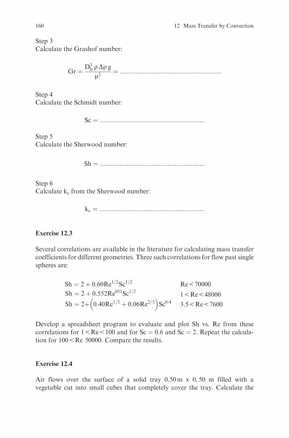
Step 3Calculate the Grashof number:
Gr ¼ D3b rDr gm2
¼ :::::::::::::::::::::::::::::::::::::::::::::::::::::::::
Step 4Calculate the Schmidt number:
Sc ¼ :::::::::::::::::::::::::::::::::::::::::::::::::::::::::::
Step 5Calculate the Sherwood number:
Sh ¼ :::::::::::::::::::::::::::::::::::::::::::::::::::::::::::
Step 6Calculate kc from the Sherwood number:
kc ¼ :::::::::::::::::::::::::::::::::::::::::::::::::::::::::::
Exercise 12.3
Several correlations are available in the literature for calculating mass transfer
coefficients for different geometries. Three such correlations for flow past single
spheres are:
Sh ¼ 2þ 0:60Re1=2Sc1=2 Re570000
Sh ¼ 2þ 0:552Re053Sc1=2
Sh ¼ 2þ 0:40Re1=2 þ 0:06Re2=3� �
Sc0:415Re548000
3:55Re57600
Develop a spreadsheet program to evaluate and plot Sh vs. Re from these
correlations for 15Re5100 and for Sc ¼ 0:6 and Sc ¼ 2. Repeat the calcula-
tion for 1005Re 50000. Compare the results.
Exercise 12.4
Air flows over the surface of a solid tray 0.50m x 0. 50 m filled with a
vegetable cut into small cubes that completely cover the tray. Calculate the
160 12 Mass Transfer by Convection

rate of water vapor transfer from the surface of the tray to the air stream ifthe mass transfer coefficient is 0.03 kg/s m2 Pa. The water vapor pressure is12000 Pa at the surface of the vegetable and 5000 Pa at the bulk of the airstream.
Solution
Step 1Draw the process diagram:
ps = 12000 Pa
pa = 5000 Pa
kG
nw
Step 2State your assumptions:The vegetable surface is covered with unbound moisture.
Step 3Calculate the mass transfer rate:
nw ¼ kGA ps � pað Þ ¼ :::::::::::::::::::::::::::::::::::::::::::::::::::::::
Exercise 12.5
Air passes through a fixed bed of corn of 6 m3 where the mass transfercoefficient is 0.05 kg/s m2 Pa and the surface area per unit volume of the bedis 60 m2/m3. The water vapor pressure at the surface of the corn is 5000 Pa at thebottom of the bed and 5500 Pa at the top. Water vapor pressure for the bulk airis 1800 Pa at the inlet and 2500 Pa at the outlet of the bed. Calculate the rate ofwater vapor transfer from the corn to the air.
Exercises 161
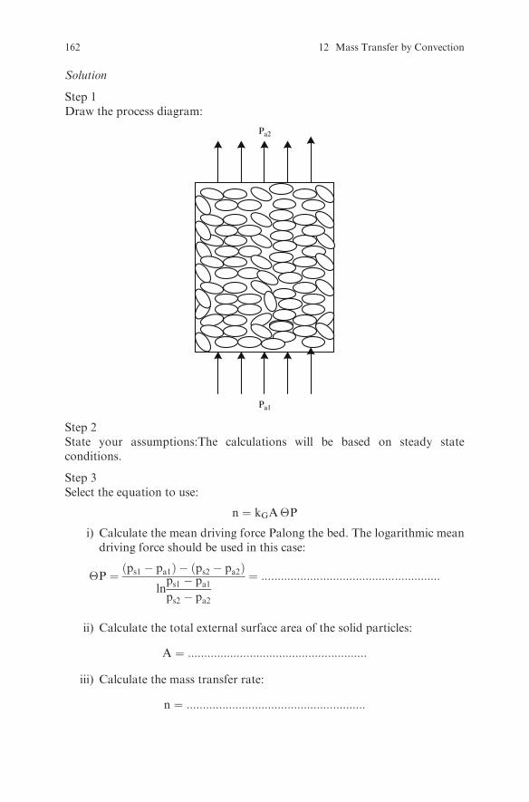
Solution
Step 1Draw the process diagram:
Pa2
Pa1
Step 2State your assumptions:The calculations will be based on steady stateconditions.
Step 3Select the equation to use:
n ¼ kGA�P
i) Calculate the mean driving force Palong the bed. The logarithmic meandriving force should be used in this case:
�P ¼ ps1 � pa1ð Þ � ps2 � pa2ð Þlnps1 � pa1ps2 � pa2
¼ :::::::::::::::::::::::::::::::::::::::::::::::::::::::
ii) Calculate the total external surface area of the solid particles:
A ¼ :::::::::::::::::::::::::::::::::::::::::::::::::::::::
iii) Calculate the mass transfer rate:
n ¼ :::::::::::::::::::::::::::::::::::::::::::::::::::::::
162 12 Mass Transfer by Convection
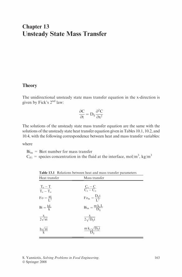
Chapter 13
Unsteady State Mass Transfer
Theory
The unidirectional unsteady state mass transfer equation in the x-direction is
given by Fick’s 2nd law:
@C
@t¼ Dij
@2C
@x2
The solutions of the unsteady state mass transfer equation are the same with the
solutions of the unsteady state heat transfer equation given inTables 10.1, 10.2, and
10.4, with the following correspondence between heat and mass transfer variables:
where
Bim = Biot number for mass transferCFi = species concentration in the fluid at the interface, mol/m3, kg/m3
Table 13.1 Relations between heat and mass transfer parameters
Heat transfer Mass transfer
Te � T
Te � To
Cs � CCs � Co
Fo ¼ atL2 Fom ¼
Dijt
L2
Bi ¼ hLk
Bim ¼ mkcLDij
x2ffiffiffiffiffiatp x
2ffiffiffiffiffiffiffiffiDijt
p
hffiffiffiffiffiatpk
mkcffiffiffiffiffiffiffiffiDijt
pDij
S. Yanniotis, Solving Problems in Food Engineering.� Springer 2008
163

CFL = species concentration in the bulk of the fluid, mol/m3, kg/m3
Cs= species concentration in the medium at the surface of the solid, mol/m3,
kg/m3
Co = initial concentration of the species in the solid, mol/m3, kg/m3
C = concentration of the species in the solid at time t and point x, mol/m3,
kg/m3
Dij = mass diffusivity, m2/sFom = Fourier number for mass transferkc = mass transfer coefficient, m/sL= characteristic dimension (half thickness of the plate, radius of a cylinder
or sphere), mm = equilibrium distribution coefficientx = distance of the point from the center plane of the plate, or from the
surface in the case of semi-infinite body, mt = time, s
To calculate the concentration as a function of time and position in a solid we
follow the same procedure as for calculating the temperature as a function of
time and position in a solid:
1. Identify the geometry of the system. Determine if the solid can be consideredas plate, infinite cylinder, or sphere.
2. Determine if the surface concentration is constant. If not, calculate the Biotnumber and decide the relative importance of internal and external resistanceto mass transfer.
3. Select the appropriate equation given for unsteady state heat transfer(Tables 10.1, 10.2, 10.4).
4. Calculate the Fourier number.5. Find the concentration by applying the selected equation (if Fo > 0:2, cal-
culate the temperature either using only the first term of the series solution orusing Heisler or Gurnie-Lurie charts).
Review Questions
Which of the following statements are true and which are false?
1. If the concentration at any given point of a body changes with time,unsteady state mass transfer occurs.
2. Fick’s 2nd law is used in unsteady state mass transfer problems.3. Gurnie-Lurie and Heisler charts are valid for unsteady state mass transfer
problems.4. The Heisler chart can be used to find the concentration at any point in a
body if the Fourier and Biot numbers are known.5. Gurnie-Lurie charts are used when Fo < 0:2.
164 13 Unsteady State Mass Transfer
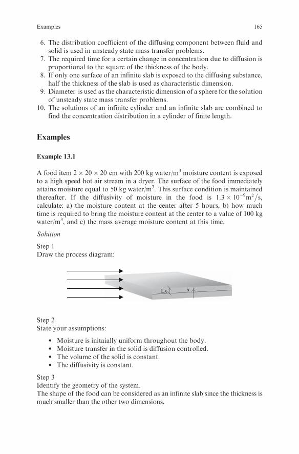
6. The distribution coefficient of the diffusing component between fluid andsolid is used in unsteady state mass transfer problems.
7. The required time for a certain change in concentration due to diffusion isproportional to the square of the thickness of the body.
8. If only one surface of an infinite slab is exposed to the diffusing substance,half the thickness of the slab is used as characteristic dimension.
9. Diameter is used as the characteristic dimension of a sphere for the solutionof unsteady state mass transfer problems.
10. The solutions of an infinite cylinder and an infinite slab are combined tofind the concentration distribution in a cylinder of finite length.
Examples
Example 13.1
A food item 2� 20� 20 cm with 200 kg water/m3 moisture content is exposedto a high speed hot air stream in a dryer. The surface of the food immediatelyattains moisture equal to 50 kg water/m3. This surface condition is maintainedthereafter. If the diffusivity of moisture in the food is 1:3� 10�9m2
�s,
calculate: a) the moisture content at the center after 5 hours, b) how muchtime is required to bring the moisture content at the center to a value of 100 kgwater/m3, and c) the mass average moisture content at this time.
Solution
Step 1Draw the process diagram:
Lx x
Step 2State your assumptions:
l Moisture is initaially uniform throughout the body.l Moisture transfer in the solid is diffusion controlled.l The volume of the solid is constant.l The diffusivity is constant.
Step 3Identify the geometry of the system.The shape of the food can be considered as an infinite slab since the thickness ismuch smaller than the other two dimensions.
Examples 165

Step 4
i) Select the appropriate equation to use.Since the surface concentration is constant, the equation is (see Tables 10.1
and 13.1).
Cs � C
Cs � Co¼ 4
p
X1n¼0
�1ð Þn
2nþ 1cos
2nþ 1ð Þpx2L
� �exp � 2nþ 1ð Þ2p2
4Fox
!(13:1)
ii) Calculate the Fourier number
Fox ¼Dt
L2x
¼1:3� 10�9m2=s� �
5� 3600 sð Þ0:01 mð Þ2
¼ 0:234
Since Fox > 0:2 the first term of the series in eqn (13.1) is enough. Alternatively,
the Heisler chart can be used.
Step 5
i) Find the concentration at the center using eqn (3.1) above:
Cs � C
Cs � Co¼ 4
p
X1n¼0
�1ð Þn
2nþ 1cos
2nþ 1ð Þpx2L
� �exp � 2nþ 1ð Þ2p2
4Fox
!
¼ 4
p�1ð Þ0
2� 0þ 1ð Þ cos2� 0þ 1ð Þ � p� 0
2� 0:01exp � 2� 0þ 1ð Þ2p2
4� 0:234
!
¼ 0:715
and
C ¼ Cs � 0:715 Cs � Coð Þ ¼ 50� 0:715 50� 200ð Þ ¼ 157 kg water=m3
ii) Find the concentration at the center using the Heisler chart for an infiniteslab (Fig A.5):
l Find the value of FO ¼ 0:234 on the x-axis.l Find the curve with 1=Bi ¼ 0.l Read the dimensionless concentration on the y-axis as:
Cs � C
Cs � Co¼ 0:7
C ¼ Cs � 0:7 Cs � Coð Þ
¼ 50� 0:7 50� 200ð Þ ¼ 155 kg water=m3
166 13 Unsteady State Mass Transfer
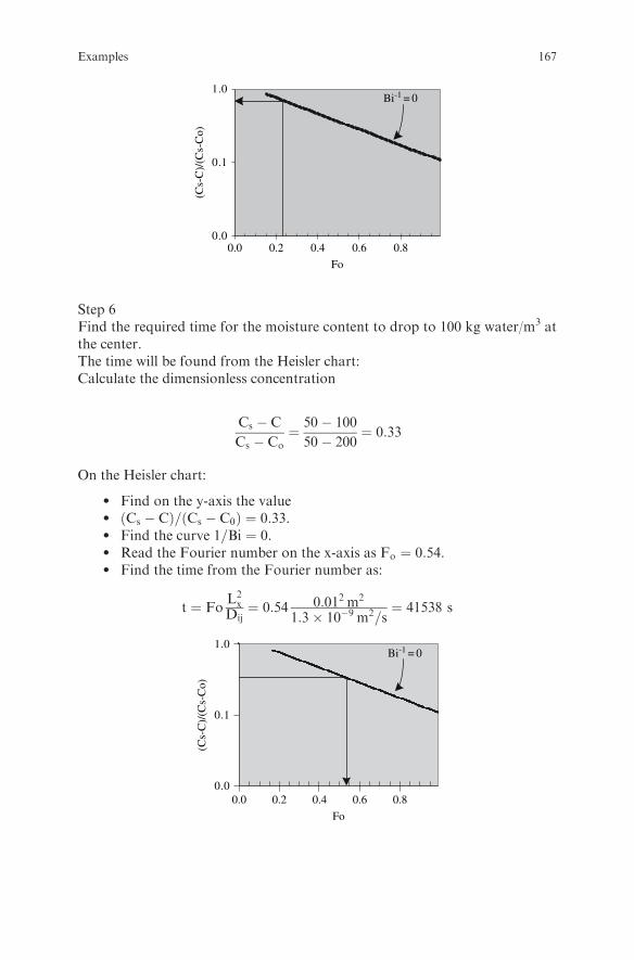
0.0
0.1
1.0
0.0 0.2 0.4 0.6 0.8
Fo
(Cs-
C)/
(Cs-
Co)
Bi-1 = 0
Step 6Find the required time for the moisture content to drop to 100 kg water/m3 atthe center.The time will be found from the Heisler chart:Calculate the dimensionless concentration
Cs � C
Cs � Co¼ 50� 100
50� 200¼ 0:33
On the Heisler chart:
l Find on the y-axis the valuel Cs � Cð Þ= Cs � C0ð Þ ¼ 0:33.l Find the curve 1=Bi ¼ 0.l Read the Fourier number on the x-axis as Fo ¼ 0:54.l Find the time from the Fourier number as:
t ¼ FoL2x
Dij¼ 0:54 0:012 m2
1:3� 10�9 m2=s¼ 41538 s
0.0 0.2 0.4 0.6 0.8
Fo
0.0
0.1
1.0
(Cs-
C)/
(Cs-
Co)
Bi-1 = 0
Examples 167

Step 7Calculate the mass average moisture content.
i) Find the equation for the mean concentration of an infinite slab withBi > 40 in Table 10.1:
Cs � Cm
Cs � Co¼ 8
p2X1n¼0
1
2nþ 1ð Þ2exp � 2nþ 1ð Þ2p2
4Fo
!
ii) Substitute the values in the above equation and solve for Cm (sinceFo > 0:2 the first term only is enough).
Cs � Cm
Cs � Co¼ 8
p2X1n¼0
1
2nþ 1ð Þ2exp � 2nþ 1ð Þ2p2
4Fo
!¼
¼ 8
p21
2� 0þ 1ð Þ2exp � 2� 0þ 1ð Þ2p2
4� 0:54
!¼ 0:214
and
Cm ¼ Cs � 0:214 Cs � Coð Þ ¼ 50� 0:214 50� 200ð Þ ¼ 82:1 kg water=m3
Exercises
Exercise 13.1
Apple slices 4 mm thick are exposed to sulphur fumes in a sulphuring housebefore drying. If the Biot number for mass transfer is higher than 40 and thesurface concentration of SO2 is 0.1 mol SO2/m
3, calculate the mass average SO2
concentration in the slices after 1 h. Assume zero initial concentration of SO2 inthe apple and a diffusion coefficient of SO2 in the apple of 1� 10�9m2
�s.
Solution
SO2
Step 1State your assumptions:
168 13 Unsteady State Mass Transfer

l Mass transfer through the sides of the slice is negligible (the solution foran infinite slab can be applied).
l Only the top of the slice is exposed to sulphur fumes.
Step 2Calculate the Fourier number.Since the food is exposed to the fumes from one side the characteristic dimensionis equal to the thickness of the slice. Therefore:
Fo ¼ ::::::::::::::::::::::::::::::::::::::::::::::::::::::::::::::::::::::::::::
Step 3Find the equation for the mean concentration of a plate with Bi > 40 inTable 10.1. Substitute the values in the equation and solve for Cm:
Cs � Cm
Cs � Co¼ :::::::::::::::::::::::::::::::::::::::::::::::::::::::::::::::::::::::::::::::::::::
and
Cm ¼ ::::::::::::::::::::::::::::::::::::::::::::::::::::::::::::::::::::::::::::::::::::::
Exercise 13.2
Calculate how long it will take for the concentration on the non-exposed surfaceof the apple slice of Exercise 13.1 to increase by 1% of the initial concentrationdifference.
Solution
Step 1Identify the geometry of the system.As long as the concentration change on the non-exposed surface of the appleslice is less than 1% of the initial concentration difference, the slice can betreated as a semi-infinite body.
Step 2Select the appropriate equation from Table 10.4.Since the surface concentration is constant, the equation for a semi-infinite bodywith uniform initial concentration and constant surface concentrationwill be used:
Cs � C
Cs � Co¼ erf
x
2ffiffiffiffiffiffiDtp
� �
Step 3The mass penetration depth is given by (as in heat transfer):
x
2ffiffiffiffiffiffiDtp ¼ :::::::::::::::::::::::::::::::::
Exercises 169
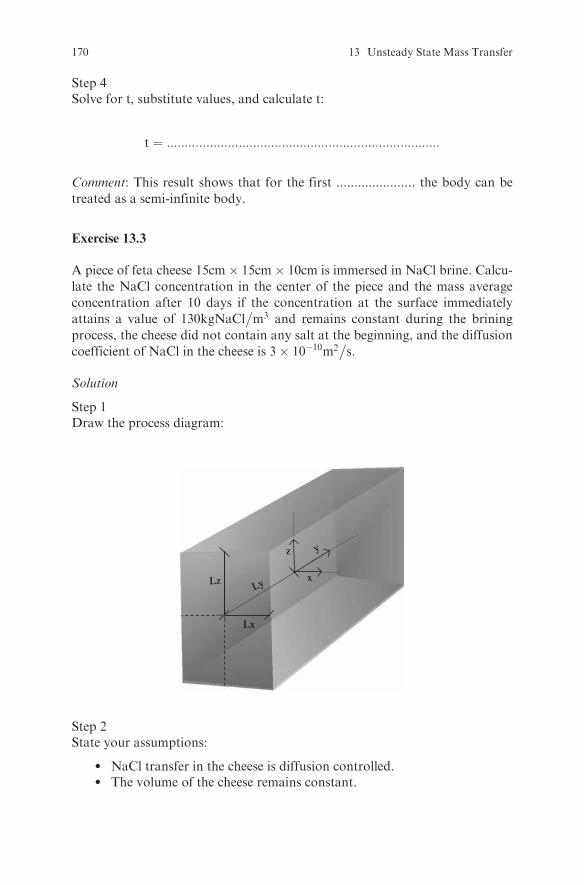
Step 4Solve for t, substitute values, and calculate t:
t ¼ ::::::::::::::::::::::::::::::::::::::::::::::::::::::::::::::::::::::::::::
Comment: This result shows that for the first ...................... the body can be
treated as a semi-infinite body.
Exercise 13.3
A piece of feta cheese 15cm� 15cm� 10cm is immersed in NaCl brine. Calcu-
late the NaCl concentration in the center of the piece and the mass average
concentration after 10 days if the concentration at the surface immediately
attains a value of 130kgNaCl�m3 and remains constant during the brining
process, the cheese did not contain any salt at the beginning, and the diffusion
coefficient of NaCl in the cheese is 3� 10�10m2�s.
Solution
Step 1Draw the process diagram:
x
z y
Lx
LzLy
Step 2State your assumptions:
l NaCl transfer in the cheese is diffusion controlled.l The volume of the cheese remains constant.
170 13 Unsteady State Mass Transfer
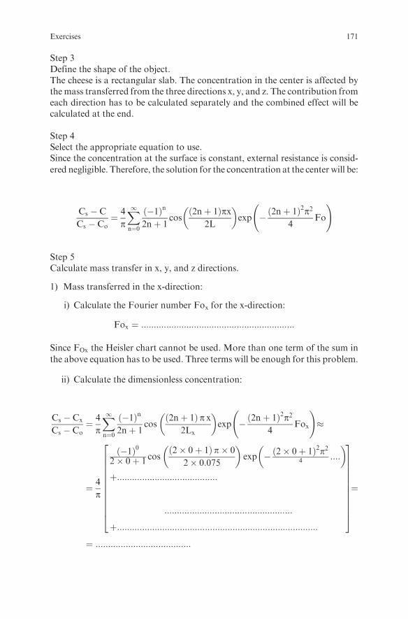
Step 3Define the shape of the object.The cheese is a rectangular slab. The concentration in the center is affected bythemass transferred from the three directions x, y, and z. The contribution fromeach direction has to be calculated separately and the combined effect will becalculated at the end.
Step 4Select the appropriate equation to use.Since the concentration at the surface is constant, external resistance is consid-
ered negligible. Therefore, the solution for the concentration at the center will be:
Cs � C
Cs � Co¼ 4
p
X1n¼0
�1ð Þn
2nþ 1cos
2nþ 1ð Þpx2L
� �exp � 2nþ 1ð Þ2p2
4Fo
!
Step 5Calculate mass transfer in x, y, and z directions.
1) Mass transferred in the x-direction:
i) Calculate the Fourier number Fox for the x-direction:
Fox ¼ :::::::::::::::::::::::::::::::::::::::::::::::::::::::::::::
Since FOx the Heisler chart cannot be used. More than one term of the sum in
the above equation has to be used. Three terms will be enough for this problem.
ii) Calculate the dimensionless concentration:
Cs � Cx
Cs � Co¼ 4
p
X1n¼0
�1ð Þn
2nþ 1cos
2nþ 1ð Þ p x2Lx
� �exp � 2nþ 1ð Þ2p2
4Fox
!�
¼ 4
p
�1ð Þ02� 0þ 1
cos2� 0þ 1ð Þ p� 0
2� 0:075
� �exp � 2� 0þ 1ð Þ2p2
4 ::::
� �
þ::::::::::::::::::::::::::::::::::::::::
:::::::::::::::::::::::::::::::::::::::::::::::::::
þ::::::::::::::::::::::::::::::::::::::::::::::::::::::::::::::::::::::::::::::::
266666666664
377777777775¼
¼ ::::::::::::::::::::::::::::::::::::::
Exercises 171
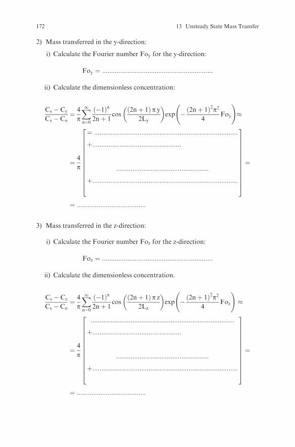
2) Mass transferred in the y-direction:
i) Calculate the Fourier number Foy for the y-direction:
Foy ¼ :::::::::::::::::::::::::::::::::::::::::::::::::::::::::::::
ii) Calculate the dimensionless concentration:
Cs � Cy
Cs � Co¼ 4
p
X1n¼0
�1ð Þn
2nþ 1cos
2nþ 1ð Þ p y2Ly
� �exp � 2nþ 1ð Þ2p2
4Foy
!�
¼ 4
p
¼ :::::::::::::::::::::::::::::::::::::::::::::::::::::::::::::::::::::::::::::::
þ:::::::::::::::::::::::::::::::::::::::::::::::::
:::::::::::::::::::::::::::::::::::::::::::::::::::
þ::::::::::::::::::::::::::::::::::::::::::::::::::::::::::::::::::::::::::::::::
2666666666664
3777777777775
¼
¼ ::::::::::::::::::::::::::::::::::::::
3) Mass transferred in the z-direction:
i) Calculate the Fourier number Foz for the z-direction:
Foz ¼ :::::::::::::::::::::::::::::::::::::::::::::::::::::::::::::
ii) Calculate the dimensionless concentration.
Cs � Cz
Cs � Co¼ 4
p
X1n¼0
�1ð Þn
2nþ 1cos
2nþ 1ð Þ p z2Lz
� �exp � 2nþ 1ð Þ2p2
4Foz
!�
¼ 4
p
:::::::::::::::::::::::::::::::::::::::::::::::::::::::::::::::::::::::::::::::
þ:::::::::::::::::::::::::::::::::::::::::::::::::
:::::::::::::::::::::::::::::::::::::::::::::::::::
þ::::::::::::::::::::::::::::::::::::::::::::::::::::::::::::::::::::::::::::::::
2666666666664
3777777777775
¼
¼ ::::::::::::::::::::::::::::::::::::::
172 13 Unsteady State Mass Transfer

4) The combined effect of mass transferred in the x, y, and z directions is:
Cs � Cxyz
Cs � Co¼ Cs � Cx
Cs � Co
� �Cs � Cy
Cs � Co
� �Cs � Cz
Cs � Co
� �
¼ ::::::::::::::::::::::::::::::::::::::::::::::
Calculate the concentration at the center as:
::::::::::::::::::� Cxyz
�
¼ :::::::::::::::::::::::: ! Cxyz ¼
Step 6The solution for the mass average concentration is:
Cs � Cm
Cs � Co¼ 8
p2X1n¼0
1
2nþ 1ð Þ2exp � 2nþ 1ð Þ2p2
4Fo
!
1) Mass transferred in the x-direction:
Cs � Cmx
Cs � Co¼ 8
p
X1n¼0
1
2nþ 1ð Þ2exp � 2nþ 1ð Þ2p2
4Fox
!¼
¼ 8
p
:::::::::::::::::::::::::::::::::::::::::::::::::::::::::::::::::::::::::::::::::::::::::
þ:::::::::::::::::::::::::::::::::::::::::
:::::::::::::::::::::::::::::::::::::::::::::::::::
þ::::::::::::::::::::::::::::::::::::::::::::::::::::::::::::::::::::::::::::::::
2666666666664
3777777777775
¼
¼ ::::::::::::::::::::::::::::::::::::::
Exercises 173

2) Mass transferred in the y-direction:
Cs � Cmy
Cs � Co¼ 8
p
X1n¼0
1
2nþ 1ð Þ2exp � 2nþ 1ð Þ2p2
4Foy
!�
¼ 8
p
::::::::::::::::::::::::::::::::::::::::þ :::::::::::::::::::::::::::::::::::::::::::::
:::::::::::::::::::::::::::::::::::::::::::::::::::þ ::::::::::::::::::::::::::::::::::
2666666664
3777777775¼
¼ ::::::::::::::::::::::::::::::::::::::
3) Mass transferred in the z-direction:
Cs � Cmz
Cs � Co¼ 8
p
X1n¼0
1
2nþ 1ð Þ2exp � 2nþ 1ð Þ2p2
4Foz
!�
¼ 8
p
::::::::::::::::::::::::::::::::::::::::::::::: þ ::::::::::::::::::::::::::::::::::::::
::::::::::::::::::::::::::::::::::::::::::::::þ ::::::::::::::::::::::::::::::::::::::::
2666664
3777775¼
¼ ::::::::::::::::::::::::::::::::::::::
4) The combined effect of mass transferred in the x, y, and z directions is:
Cs � Cmxyz
Cs � Co¼ Cs � Cmx
Cs � Co
� �Cs � Cmy
Cs � Co
� �Cs � Cmz
Cs � Co
� �
¼ :::::::::::::::::::::::::::::::::::::::
Calculate the mass average concentration as:
::::::::::::::::::� Cmxyz
Cmxyz ¼ ::::::::::::::::::::::::::::::::::
¼ ::::::::::::::::::::::::!
Exercise 13.4
To remove the excess salt from salt-stock cucumbers in a pickle factory, the
cucumbers are immersed in several changes of fresh water. Calculate the
174 13 Unsteady State Mass Transfer

average NaCl concentration in a cucumber after 5 hours of immersion in freshwater if the cucumber has 2 cm diameter and 6 cm length, the initial NaClcontent is 100 kg NaCl/m3, and the diffusivity of NaCl in the cucumber is1� 10�9m2
�s. Assume that the change of water is continuous so that the salt
concentration in the water is zero.
Solution
Step 1Draw the process diagram:
r
L xD
Step 2State your assumptions:
l The external resistance to mass transfer is negligible so that ................................................................................................................................
l Diffusion through the ends of the pickle is negligiblel ................................................................................................................
Step 3Identify the geometry of the system.The pickle will be treated as an infinitely long cylinder:
Step 4Select the equation to use.The solution for the mean concentration for a cylinder with constant surfaceconcentration will be applied for the cylindrical surface, that is:
Cs � Cm
Cs � Co¼ 4
p2X1n¼1
p2
R2d2nexp �R2d2nFor� �
¼
¼ 4
p2
�1:7066expð � 5:783ForÞ þ 0:324expð � 30:5ForÞ
þ 0:132expð � 74:9ForÞ þ :::
Step 5Calculate the Fourier number:
For ¼ :::::::::::::::::::::::::::::::::::::::::::::::::::
Exercises 175

Since For40:2, more than one term of the sum in the above equation will be
used. Two terms are enough for this case. Verify that even the contribution of
the 2nd term is small.Step 6Substitute the values in the above equation and solve for Cm:
Cs � Cm
Cs � Co� 4
p21:7066expð � 5:783ForÞ þ 0:324expð � 30:5ForÞð Þ ¼
¼ ::::::::::::::::::::::::::::::::::::::::::::::::::::::::::::::::::::::::::::::::::::::: ¼
¼ :::::::::::::::::::::::::
and
Cm ¼ ::::::::::::::::::::::::::::::::::::::::::::::::::::::
.
Exercise 13.5
The moisture content of the soil in a field is 200 kg water/m3, when suddenly dry
air starts blowing. Calculate the moisture content of the soil 5 cm below the
surface after 48 hours if the diffusion coefficient of water in the soil is 1:3�10�8m2
�s and the equilibriummoisture content of the soil in contact with the air
is 100 kgwater/m3. Assume that the surface immediately equilibrates with the air.
Solution
Step 1Draw the process diagram:
Cs = 100 kg/m3
x
Co = 100 kg/m3
Bi > 40
176 13 Unsteady State Mass Transfer
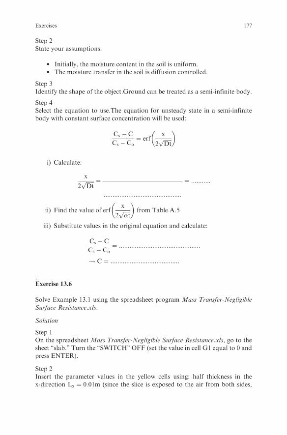
Step 2State your assumptions:
l Initially, the moisture content in the soil is uniform.l The moisture transfer in the soil is diffusion controlled.
Step 3Identify the shape of the object.Ground can be treated as a semi-infinite body.
Step 4Select the equation to use.The equation for unsteady state in a semi-infinitebody with constant surface concentration will be used:
Cs � C
Cs � Co¼ erf
x
2ffiffiffiffiffiffiDtp
� �
i) Calculate:
x
2ffiffiffiffiffiffiDtp ¼
::::::::::::::::::::::::::::::::::::::::::::
¼ :::::::::::
ii) Find the value of erfx
2ffiffiffiffiffi�tp
� �from Table A.5
iii) Substitute values in the original equation and calculate:
Cs � C
Cs � Co¼ ::::::::::::::::::::::::::::::::::::::::::::::
! C ¼ :::::::::::::::::::::::::::::::::::::::
.Exercise 13.6
Solve Example 13.1 using the spreadsheet program Mass Transfer-Negligible
Surface Resistance.xls.
Solution
Step 1On the spreadsheet Mass Transfer-Negligible Surface Resistance.xls, go to thesheet ‘‘slab.’’ Turn the ‘‘SWITCH’’ OFF (set the value in cell G1 equal to 0 andpress ENTER).
Step 2Insert the parameter values in the yellow cells using: half thickness in thex-direction Lx ¼ 0:01m (since the slice is exposed to the air from both sides,
Exercises 177

Lx is taken equal to half thickness), half thickness in the y-direction Ly ¼ 0:10m,half thickness in the z-direction Lz ¼ 0:10m, x ¼ 0, y ¼ 0 and z ¼ 0 (since theconcentration will be calculated at the center), initial moisture contentCo ¼ 200kgwater
�m3, surface concentration Cs ¼ 50kgwater
�m3. Also insert
the given value for the diffusivity.
Step 3Set the value of the time step to 120 s (or some other value) in cell F4.
Step 4Turn the ‘‘SWITCH’’ ON (set the value in cell G1 equal to 1 and press ENTER).
Step 5Iterate by pressing F9 until the moisture in cell K20 reaches the value 100.
Step 6Read the mass average moisture content in cell K40. Observe if theaverage moisture is affected by the mass transferred from the y and zdirections.
Step 7To see how the mass average concentration would have decreased if the slicewas exposed to the air from one side only:
xLx
i) Turn the ‘‘SWITCH’’ OFF (set the value in cell G1 equal to 0 and pressENTER).
ii) Set the value of half thickness in the x-direction to Lx ¼ 0:02m.iii) Set the value of the coordinates of the point to x ¼ 0,y ¼ 0 and z ¼ 0.vi) Turn the ‘‘SWITCH’’ ON (set the value in cell G1 equal to 1 and press
ENTER).v) Iterate by pressing F9 until the mass average moisture in cell K40 reaches
the same value as in 6 above.vi) Read the time in cell F3. Compare the two time values.
Exercise 13.7
Small identical cubes 2cm� 2cm� 2cm of a cheese-like product were dry-
salted (covered with dry NaCl crystals). From time to time, one cube was
178 13 Unsteady State Mass Transfer

taken out and analyzed for NaCl and moisture content. Calculate the diffusion
coefficient of NaCl in the cheese if the following average NaCl concentration vs.
time data were obtained.
Time, h kg NaCl/m3
0 3
2 122
6 163
10 194
24 206
30 215
48 221
60 221
Solution
Step 1State your assumptions:..........................................................................................................................
Step 2On the spreadsheet Mass Transfer-Negligible Surface Resistance.xls, go to thesheet ‘‘slab.’’ Turn the ‘‘SWITCH’’ OFF (set the value in cell G1 equal to 0 andpress ENTER).
Step 3Insert the parameter values in the yellow cells using: half thickness in thex-direction Lx = 0.01 m, half thickness in the y-direction Lx ¼ 0:01m, halfthickness in the z-direction Lz ¼ 0:01m, x ¼ 0, y ¼ 0 and z ¼ 0, initial NaClcontent Co ¼ 3kgNaCl
�m3, surface concentration Cs ¼ 221kgNaCl
�m3.
Step 4Insert a first trial value for the diffusivity.
Step 5Set the value of the time step to 1000 s (or some other value) in cell F4.
Step 6Turn the ‘‘SWITCH’’ ON (set the value in cell G1 equal to 1 and press ENTER).
Step 7Iterate by pressing F9 until the mass average NaCl concentration in cell K40reaches the value of 221 (final experimental concentration).
Exercises 179

Step 8Calculate the mean % deviation between the experimental values and thetheoretically predicted values of a mass average concentration of NaCl from:
Deviation % ¼ 100
N
XN1
Cexp � Ctheor
Cexp
Step 9Turn the ‘‘SWITCH’’ OFF (set the value in cell G1 equal to 0 and pressENTER).
Step 10Insert a second trial value for the diffusivity in cell B38.
Step 11Turn the ‘‘SWITCH’’ ON (set the value in cell G1 equal to 1 and press ENTER)
Step 12Iterate by pressing F9 until the mass average NaCl concentration in cell K40reaches the value 221.
Step 13Calculate the mean % deviation between the experimental values and thetheoretically predicted values of a mass average concentration of NaCl asabove.
Step 14Repeat steps 9 to 13 until a minimum deviation % is reached.
Exercise 13.8
Solve Exercises 13.1, 13.2, 13.3, and 13.4 using the spreadsheet Mass Transfer-Negligible Surface Resistance.xls.
180 13 Unsteady State Mass Transfer
Chapter 14
Pasteurization and Sterilization
Review Questions
Which of the following statements are true and which are false?
1. The decimal reduction time D is the heating time in min at a certaintemperature required for the number of viable microbes to be reduced to10% of the original number.
2. The z value is the temperature increase required for a ten-fold decreasein D.
3. Thermal death time is the heating time required to give commercialsterility.
4. Thermal death time does not depend on the initial microbial load.5. The D value does not depend on the initial microbial load.6. The D value of a microorganism is independent of the food item.7. The D value of a microbe is a measure of the thermal resistance of the
microbe.8. If the number of microbes in a process has to be reduced from an initial load
of 106 to a final 10�4, the required thermal death time will be 10D.9. If the number of microbes in a canned product is reduced from 103 to 10�4,
it means that 1 can in 100000 may be spoiled.10. As the process temperature increases, the thermal death time increases.11. A 10D process is usually applied as a minimum heat treatment for
Clostridium botulinum.12. Typical z values are 5.5 8C for vegetative cells, 10 8C for spores, and 22 8C
for nutrients.13. A D121.1 = 0.21 min is usually assumed for Clostridium botulinum.14. The accepted risk for Clostridium botulinum is 10�12.15. The accepted spoilage probability for mesophilic spoilage microorganisms
is usually 10�5.16. The accepted spoilage propability for thermophilic spoilage microorgan-
isms upon incubation after processing is usually 10�2.17. The slowest heating point of a can filled with a liquid food is the geometric
center of the can.
S. Yanniotis, Solving Problems in Food Engineering.� Springer 2008
181
18. The worst case scenario for calculating the lethal effect in a holding tube fora Newtonian liquid is to assume that the residence time is half the meanresidence time.
19. In calculating the lethal effect in a solid particulate flowing in a two-phaseflow in a holding tube, the convective heat transfer resistance at the surfaceof the particulate can be neglected.
20. The Ball Formula method is an alternative method to the general methodfor calculating the lethal effect of a sterilization process.
21. For the purpose of thermal processing, foods are divided into low acidfoods (pH > 4:5) and high acid foods (pH<4.5).
22. High acid foods need more heat treatment than low acid foods.23. Clostridium botulinum is of concern in high acid foods.24. Spoilage microorganisms is the major concern in low acid foods.25. Thermal treatment of high acid foods is usually carried out at temperatures�100 8C.
Examples
Example 14.1
The decimal reduction time D at 121 8C (D121) and the value z for a thermo-
philic spore in whole milk were determined experimentally to be equal to 30 s
and 10.5 8C respectively. Calculate the D value at 150 8C (D150).
Solution
Step 1The effect of temperature on D is given by:
DT1¼ DT2
10T2�T1
z (14:1)
Step 2Substitute values in eqn (14.1) and calculate D150:
D150 ¼ 0:5� 10
121�15010:5 ¼ 0:000865min
Example 14.2
Determine the required heating time at 121 8C, F121 value, in the case of
Example 14.1 for a 9 log cycles population reduction.
182 14 Pasteurization and Sterilization

Solution
Step 1The required F value at temperature T for a certain population reduction isgiven by:
FT ¼ DTlogNo
N(14:2)
e.g., for 12 log cycles population reduction, F=12D.Equation (14.2) can be used to convert log cycles of reduction into FT (min at T)if DT is known.
Step 2Substitute values in eqn (14.2) and find F121:
F121 ¼ D121logNo
N¼ 0:5� 9 ¼ 4:5 min
Thus the sterilizing value or the lethality for this process is F = 4.5 min.
Example 14.3
Find two equivalent processes, at 100 8C and 150 8C, which will deliver the samelethality as the required F121 value of 4.5 min calculated in the previousexample.
Solution
Step 1State your assumptions: All thermal treatment is delivered at a constanttemperature of 100 8C or 150 8C.
Step 2The delivered F value by a process at temperature T equivalent to a referenceprocess FR at TR is given by:
FT ¼ FR � 10TR�T
z (14:3)
Step 3Substitute values in eqn (14.3) and find FT:
F100 ¼ F121 � 10
121�Tz ¼ 4:5� 10
121�10010:5 ¼ 450min
F150 ¼ F121 � 10121�T
z ¼ 4:5� 10121�15010:5 ¼ 0:0078min
Examples 183
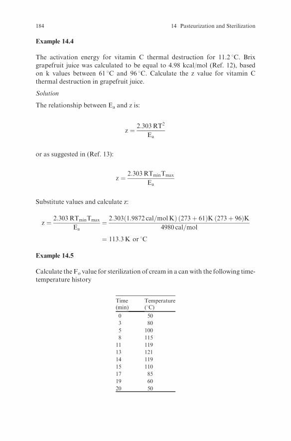
Example 14.4
The activation energy for vitamin C thermal destruction for 11.2 8C. Brix
grapefruit juice was calculated to be equal to 4.98 kcal/mol (Ref. 12), based
on k values between 61 8C and 96 8C. Calculate the z value for vitamin C
thermal destruction in grapefruit juice.
Solution
The relationship between Ea and z is:
z ¼ 2:303RT2
Ea
or as suggested in (Ref. 13):
z ¼ 2:303RTminTmax
Ea
Substitute values and calculate z:
z ¼ 2:303RTminTmax
Ea¼ 2:303 1:9872 cal=molKð Þ 273þ 61ð ÞK 273þ 96ð ÞK
4980 cal=mol
¼ 113:3K or 8C
Example 14.5
Calculate the Fo value for sterilization of cream in a can with the following time-
temperature history
Time Temperature(min) (8C)
0 50
3 80
5 100
8 115
11 119
13 121
14 119
15 110
17 85
19 60
20 50
184 14 Pasteurization and Sterilization
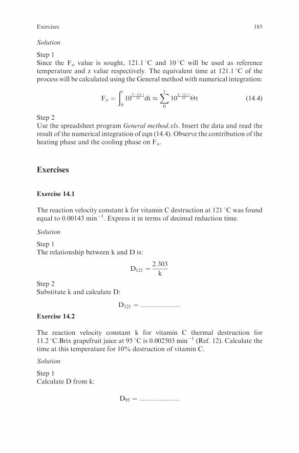
Solution
Step 1Since the Fo value is sought, 121.1 8C and 10 8C will be used as referencetemperature and z value respectively. The equivalent time at 121.1 8C of theprocess will be calculated using the General method with numerical integration:
Fo ¼ðt0
10T�121:1
10 dt �Xt0
10T�121:1
10 �t (14:4)
Step 2Use the spreadsheet program General method.xls. Insert the data and read theresult of the numerical integration of eqn (14.4). Observe the contribution of theheating phase and the cooling phase on Fo.
Exercises
Exercise 14.1
The reaction velocity constant k for vitamin C destruction at 121 8C was foundequal to 0.00143 min�1. Express it in terms of decimal reduction time.
Solution
Step 1The relationship between k and D is:
D121 ¼2:303
k
Step 2Substitute k and calculate D:
D121 ¼ ::::::::::::::::::::::Exercise 14.2
The reaction velocity constant k for vitamin C thermal destruction for11.2 8C.Brix grapefruit juice at 95 8C is 0.002503 min�1 (Ref. 12). Calculate thetime at this temperature for 10% destruction of vitamin C.
Solution
Step 1Calculate D from k:
D95 ¼ ::::::::::::::::::::::
Exercises 185
Step 2Calculate the required time from an equation analogous to eqn (14.2) ofExample 14.2 above.
t ¼ D95logCo
C¼ :::::::::::::::::::::::::::::::::::::::::::::::::::::::::::::::
Exercise 14.3
The following time-temperature history was recorded during pasteurization
of grapefruit juice. Calculate the thermal destruction of vitamin C due to
pasteurization.
Time Temperature(s) (8C)
0 20
5 50
8 65
11 75
13 82
18 90
30 90
32 80
35 60
40 45
50 30
Solution
Step 1Find the equivalent time of the process at 95 8C using the General method withnumerical integration as in step 1 of Example 14.5. Use the z value found inExample 14.4. Use the spreadsheet programGeneral method.xls. Insert the dataand read the result.
Step 2Use the D95 value found in Exercise 14.2 and calculate C/Co from a relationshipanalogous to eqn (14.2) of Example 14.2.
C
Co¼ ::::::::::::::::::::::::::::::::::::::::::::::::::::::::::::::::::::::::::::
Exercise 14.4
Experimental data from various sources presented in Ref. 12 indicate that the
energy of activation for thermal destruction of vitamin B1 in certain vegetables
186 14 Pasteurization and Sterilization

and meat is in the range of 26–28 kcal/mol based on k values between 70.5 8Cand 149 8C with k1098C = 0.0063 min�1. Calculate the loss of vitamin B1 due to
thermal destruction in the case of cooking the meat for 90 min at 100 8C or
alternatively for 30 min in a pressure cooker at 115 8C
Solution
Step 1Calculate the z value and D109 value:
z ¼ ::::::::::::::::::::::::::::::::::::::::::::::::::::::::::::::::
D109 ¼ ::::::::::::::::::::::::::::::::::::::::::::::::::::::::::::::::
Step 2Calculate the D100 and D115 values:
D100 ¼ ::::::::::::::::::::::::::::::::::::::::::::::::::::::::::::::::
D115 ¼ ::::::::::::::::::::::::::::::::::::::::::::::::::::::::::::::::
Step 3Calculate the vitamin loss at 100 8C and 115 8C:
C
Co
� �100oC
¼ ::::::::::::::::::::::::::::::::::::::::::::::::::::::::::::::::
C
Co
� �115oC
¼ ::::::::::::::::::::::::::::::::::::::::::::::::::::::::::::::::
Exercise 14.5
For an initial spore load equal to 20 spores per can and a food spoilage
microorganism with D121 = 1 min, calculate the spoilage probability if an
F equivalent to F121 = 6 min was applied.
Solution
Calculate N from eqn (14.2):
N ¼ ::::::::::::::::::::::::::::::::::::::::::::::::::::::::::::::::
Therefore, the spoilage probability is:
..........................................................................................................................
or 1 can in ........................ cans.
Exercises 187
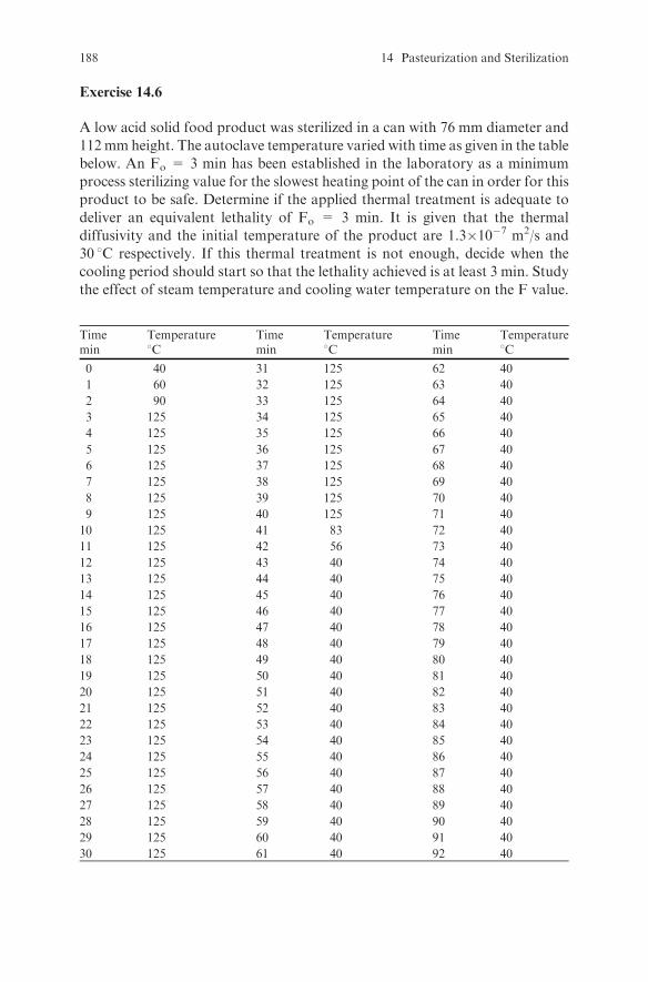
Exercise 14.6
A low acid solid food product was sterilized in a can with 76 mm diameter and
112mmheight. The autoclave temperature varied with time as given in the table
below. An Fo = 3 min has been established in the laboratory as a minimum
process sterilizing value for the slowest heating point of the can in order for this
product to be safe. Determine if the applied thermal treatment is adequate to
deliver an equivalent lethality of Fo = 3 min. It is given that the thermal
diffusivity and the initial temperature of the product are 1.3�10�7 m2/s and
30 8C respectively. If this thermal treatment is not enough, decide when the
cooling period should start so that the lethality achieved is at least 3 min. Study
the effect of steam temperature and cooling water temperature on the F value.
Time Temperature Time Temperature Time Temperaturemin 8C min 8C min 8C
0 40 31 125 62 40
1 60 32 125 63 40
2 90 33 125 64 40
3 125 34 125 65 40
4 125 35 125 66 40
5 125 36 125 67 40
6 125 37 125 68 40
7 125 38 125 69 40
8 125 39 125 70 40
9 125 40 125 71 40
10 125 41 83 72 40
11 125 42 56 73 40
12 125 43 40 74 40
13 125 44 40 75 40
14 125 45 40 76 40
15 125 46 40 77 40
16 125 47 40 78 40
17 125 48 40 79 40
18 125 49 40 80 40
19 125 50 40 81 40
20 125 51 40 82 40
21 125 52 40 83 40
22 125 53 40 84 40
23 125 54 40 85 40
24 125 55 40 86 40
25 125 56 40 87 40
26 125 57 40 88 40
27 125 58 40 89 40
28 125 59 40 90 40
29 125 60 40 91 40
30 125 61 40 92 40
188 14 Pasteurization and Sterilization
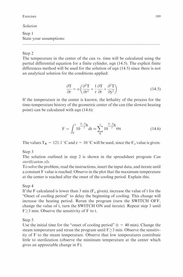
Solution
Step 1State your assumptions:..........................................................................................................................
Step 2The temperature in the center of the can vs. time will be calculated using thepartial differential equation for a finite cylinder, eqn (14.5). The explicit finitedifferences method will be used for the solution of eqn (14.5) since there is notan analytical solution for the conditions applied:
@T
@r¼ � @2T
@r2þ 1
r
@T
@rþ @
2T
@y2
� �(14:5)
If the temperature in the center is known, the lethality of the process for the
time-temperature history of the geometric center of the can (the slowest heating
point) can be calculated with eqn (14.6):
F ¼Z0
t
10
T�TRz dt �
Xt0
10
T�TRz �t (14:6)
The values TR=121.1 8C and z= 10 8Cwill be used, since the Fo value is given.
Step 3The solution outlined in step 2 is shown in the spreadsheet program Cansterilization.xls.To solve the problem, read the instructions, insert the input data, and iterate until
a constant F value is reached. Observe in the plot that themaximum temperature
at the center is reached after the onset of the cooling period. Explain this.
Step 4If the F calculated is lower than 3 min (Fo given), increase the value of t for the‘‘Onset of cooling period’’ to delay the beginning of cooling. This change willincrease the heating period. Rerun the program (turn the SWITCH OFF,change the value of t, turn the SWITCH ON and iterate). Repeat step 3 untilF�3 min. Observe the sensitivity of F to t.
Step 5Use the initial time for the ‘‘onset of cooling period’’ (t = 40 min). Change thesteam temperature and rerun the program until F�3 min. Observe the sensitiv-ity of F to the steam temperature. Observe that low temperatures contributelittle to sterilization (observe the minimum temperature at the center whichgives an appreciable change in F).
Exercises 189
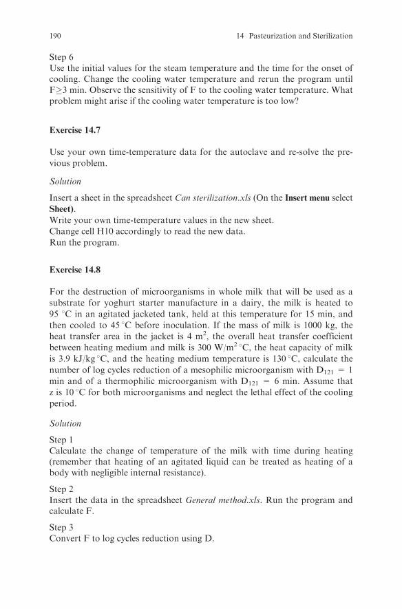
Step 6Use the initial values for the steam temperature and the time for the onset ofcooling. Change the cooling water temperature and rerun the program untilF�3 min. Observe the sensitivity of F to the cooling water temperature. Whatproblem might arise if the cooling water temperature is too low?
Exercise 14.7
Use your own time-temperature data for the autoclave and re-solve the pre-
vious problem.
Solution
Insert a sheet in the spreadsheet Can sterilization.xls (On the Insert menu select
Sheet).
Write your own time-temperature values in the new sheet.
Change cell H10 accordingly to read the new data.
Run the program.
Exercise 14.8
For the destruction of microorganisms in whole milk that will be used as a
substrate for yoghurt starter manufacture in a dairy, the milk is heated to
95 8C in an agitated jacketed tank, held at this temperature for 15 min, and
then cooled to 45 8C before inoculation. If the mass of milk is 1000 kg, the
heat transfer area in the jacket is 4 m2, the overall heat transfer coefficient
between heating medium and milk is 300 W/m2 8C, the heat capacity of milk
is 3.9 kJ/kg 8C, and the heating medium temperature is 130 8C, calculate the
number of log cycles reduction of a mesophilic microorganism with D121 = 1
min and of a thermophilic microorganism with D121 = 6 min. Assume that
z is 10 8C for both microorganisms and neglect the lethal effect of the cooling
period.
Solution
Step 1Calculate the change of temperature of the milk with time during heating(remember that heating of an agitated liquid can be treated as heating of abody with negligible internal resistance).
Step 2Insert the data in the spreadsheet General method.xls. Run the program andcalculate F.
Step 3Convert F to log cycles reduction using D.
190 14 Pasteurization and Sterilization

Exercise 14.9
Assume that the acceptable level of spoilage risk for a canned food is 1 can in100000 (spoilage probability of 10�5). Calculate the required F value if theinitial microbiological load is 50 spores per can with D121 = 1 min.
Exercise 14.10
Beer is pasteurized at 71 8C for 15 s or 74 8C for 10 s. Calculate z.
Exercise 14.11
The minimum pasteurization requirement in the USA for liquid eggs accordingto Ref. 14 is 60 8C for 3.5 min, while in Great Britain it is 64.4 8C for 2.5 min.Assuming that these treatments are equivalent, calculate the required time foran equivalent treatment in Denmark, where the pasteurization temperaturecould be up to 69 8C.
Exercises 191

Chapter 15
Cooling and Freezing
Review Questions
Which of the following statements are true and which are false?
1. Ammonia (R 717) as a refrigerant in industrial refrigeration systems has awide range of evaporating and condensing temperatures, but its vapors aretoxic and form flammable mixtures with air.
2. Tubing in ammonia refrigeration units is made of copper.3. A disadvantage of ammonia as a refrigerant is its low value of latent heat of
vaporization.4. The higher the value of the latent heat of vaporization of a refrigerant the
lower the required refrigerant flow rate for a given refrigeration load.5. Refrigerants containing chlorine may reach the upper atmosphere, react
with ozone, and deplete the ozone layer.6. Hydrofluorocarbons (HFCs) are replacing chlorofluorocarbons (CFCs) as
refrigerants.7. HFC-134a is used in refrigeration systems with moderately low
temperatures.8. Refrigerant 404a is used in refrigeration systems with low temperature
applications.9. Compressor, evaporator, condenser, and expansion valve are the main
components of a mechanical refrigeration system.10. Expansion of the refrigerant in the expansion valve of a Carnot cycle takes
place at constant entropy.11. Compression of the refrigerant in the compressor takes place at constant
enthalpy.12. Evaporation of the refrigerant in the evaporator takes place at constant
pressure.13. The condenser is at the low pressure side of amechanical refrigeration system.14. The latent heat of vaporization of the refrigerant is absorbed from the
surroundings of the evaporator.15. Refrigerant vapors leaving the evaporator may be superheated.16. Liquid refrigerant leaving the condenser may be subcooled.
S. Yanniotis, Solving Problems in Food Engineering.� Springer 2008
193

17. The coefficient of performance (COP) is equal to the ratio of the refrigera-tion effect to the net work input.
18. COP is always less than one.19. The higher the temperature difference between condenser and evaporator,
the higher the COP.20. Refrigeration load includes heat transferred into the refrigeration space by
conduction through the walls and by air entering into the space, heatremoved from the product, heat generated by the product, heat generatedby lights, motors, and people
21. Water evaporation from the surface of the product can result in consider-able weight loss in blast air freezers.
22. Individually quick frozen (IQF) products can be produced in belt freezersand fluidized bed freezers.
23. Cryogenic freezing results in frozen products with large ice crystals.24. The rate of freezing in plate freezers is high.25. Water activity of a frozen product is only a function of temperature.26. Bound water does not freeze.27. Bound water affects water activity of a frozen product.28. As water in a solution changes to ice, solute concentration increases and
freezing point decreases.29. Heat capacity and thermal conductivity below the freezing point change
significantly with temperature.30. Thawing is slower than freezing because the thermal conductivity of ice is
lower than that of water.
Examples
Example 15.1
Lettuce was vacuum-cooled and then loaded into a refrigerated car for shipmentto amarket. The tripwill last 48 h. Calculate the total amount of heat removed andthe peak refrigeration load (maximum heat removal rate) if: the amount of lettuceloaded is 3000 kg, the temperature in the truck is 2 8C, the temperature of lettucewhen loaded is 5 8C and will drop to 2 8C in 2 h, the heat capacity of lettuce is4.02 kJ/kg 8C, the area of the walls of the truck is 80 m2, the overall heat transfercoefficient for the walls is 0.3 W/m2 8C, the outside air temperature is 20 8C, andthe heat of respiration of lettuce in the temperature range of 2 to 5 8C is 35x10�3
W/kg.
Solution
Step 1State your assumptions:
l The truck is initially at 2 8C.l The truck is tightly closed so that air leakages are negligible.l The cooling requirements of the packaging material are neglected.
194 15 Cooling and Freezing
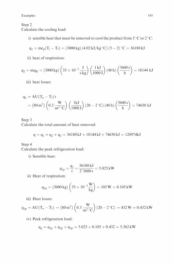
Step 2Calculate the cooling load:
i) sensible heat that must be removed to cool the product from 5 8C to 2 8C:
q1 ¼ mcp Ti � Tfð Þ ¼ 3000 kgð Þ 4:02 kJ=kg 8Cð Þ 5� 2ð Þ 8C ¼ 36180 kJ
ii) heat of respiration:
q2 ¼ mqR ¼ 3000 kgð Þ 35� 10�3J
s kg
� �1 kJ
1000 J
� �48 hð Þ 3600 s
h
� �¼ 18144 kJ
iii) heat losses:
q3 ¼ AU Ta � Tfð Þ t
¼ 80m2� �
0:3W
m2 8C
� �1kJ
1000 J
� �20� 2 8Cð Þ 48 hð Þ 3600 s
h
� �¼ 74650 kJ
Step 3Calculate the total amount of heat removed:
q ¼ q1 þ q2 þ q3 ¼ 36180 kJþ 18144 kJþ 74650 kJ ¼ 128974kJ
Step 4Calculate the peak refrigeration load:
i) Sensible heat:
q1p ¼q1t¼ 36180 kJ
2�3600 s¼ 5:025 kW
ii) Heat of respiration:
q2p ¼ 3000 kgð Þ 35� 10�3W
kg
� �¼ 105W ¼ 0:105 kW
iii) Heat losses:
q3p ¼ AU Ta � Tfð Þ ¼ 80m2� �
0:3W
m2 8C
� �20� 2 8Cð Þ ¼ 432W ¼ 0:432 kW
iv) Peak refrigeration load:
qp ¼ q1p þ q2p þ q3p ¼ 5:025þ 0:105þ 0:432 ¼ 5:562 kW
Examples 195
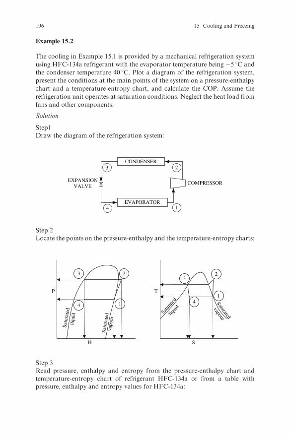
Example 15.2
The cooling in Example 15.1 is provided by a mechanical refrigeration system
using HFC-134a refrigerant with the evaporator temperature being �5 8C and
the condenser temperature 40 8C. Plot a diagram of the refrigeration system,
present the conditions at the main points of the system on a pressure-enthalpy
chart and a temperature-entropy chart, and calculate the COP. Assume the
refrigeration unit operates at saturation conditions. Neglect the heat load from
fans and other components.
Solution
Step1Draw the diagram of the refrigeration system:
COMPRESSOREXPANSIONVALVE
EVAPORATOR
CONDENSER
14
3 2
Step 2Locate the points on the pressure-enthalpy and the temperature-entropy charts:
1
23
4
P
H
Satu
rate
dliq
uid
Satu
rate
dva
pour
1
23
4
T
S
Satu
rated
liqui
d
Saturated
vapour
Step 3Read pressure, enthalpy and entropy from the pressure-enthalpy chart andtemperature-entropy chart of refrigerant HFC-134a or from a table withpressure, enthalpy and entropy values for HFC-134a:
196 15 Cooling and Freezing
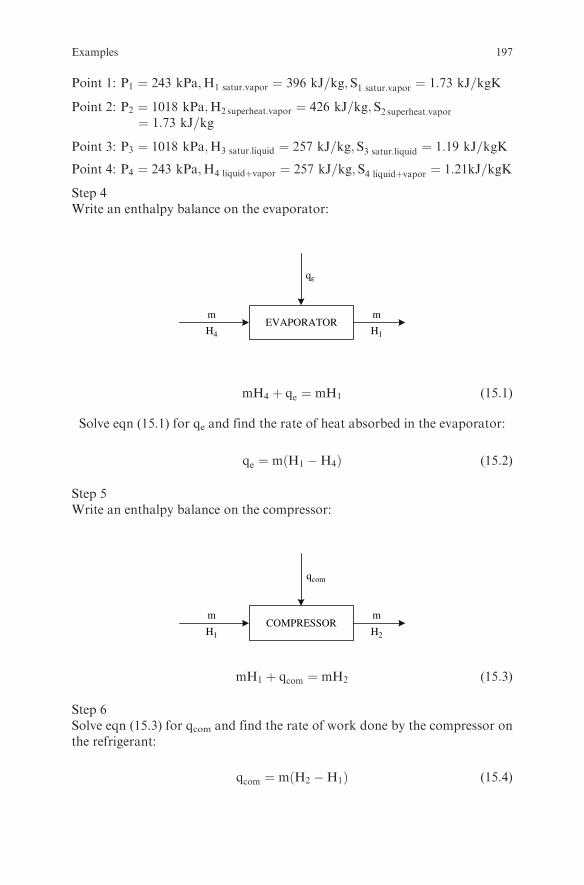
Point 1: P1 ¼ 243 kPa;H1 satur:vapor ¼ 396 kJ=kg; S1 satur:vapor ¼ 1:73 kJ=kgK
Point 2: P2 ¼ 1018 kPa;H2superheat:vapor ¼ 426 kJ=kg; S2 superheat:vapor¼ 1:73 kJ=kg
Point 3: P3 ¼ 1018 kPa;H3 satur:liquid ¼ 257 kJ=kg; S3 satur:liquid ¼ 1:19 kJ=kgK
Point 4: P4 ¼ 243 kPa;H4 liquidþvapor ¼ 257 kJ=kg; S4 liquidþvapor ¼ 1:21kJ=kgK
Step 4Write an enthalpy balance on the evaporator:
m m
qε
H4 H1EVAPORATOR
mH4 þ qe ¼ mH1 (15:1)
Solve eqn (15.1) for qe and find the rate of heat absorbed in the evaporator:
qe ¼ m H1 �H4ð Þ (15:2)
Step 5Write an enthalpy balance on the compressor:
m m
qcom
H1 H2COMPRESSOR
mH1 þ qcom ¼ mH2 (15:3)
Step 6Solve eqn (15.3) for qcom and find the rate of work done by the compressor onthe refrigerant:
qcom ¼ m H2 �H1ð Þ (15:4)
Examples 197

Step 7Calculate the COP:
COP ¼ qeqcom
¼ m H1 �H4ð Þm H2 �H1ð Þ ¼
H1 �H4
H2 �H1¼ 396� 257
426� 396¼ 4:6
Comment: The calculated COP value is higher than in practice due to the ideal
conditions assumed. Actual COP values are usually in the range of 1 to 2.
Exercise 15.3
Calculate the water activity of frozen bread at �10 8C.
Solution
The water activity at subfreezing temperatures depends only on temperature.
It can be calculated from Ref. 11:
ln awð Þ ¼ 0:00969T ¼ 0:00969� �10ð Þ ¼ �0:0969
which gives:
aw ¼ 0:908
Example 15.4
Calculate the effective molecular weight of solutes, as well as the weight fraction
of bound water, of freezable water, and of ice, for lean sirloin beef at �20 8C if
the moisture content of the unfrozen beef is 71.7% and the initial freezing point
is �1.7 8C.
Solution
Step 1State your assumptions: The activity coefficient for water in beef is 1.
Step 2Calculate Xw, the effective mole fraction of water in the unfrozen food:
ln Xwð Þ ¼ � 18:02�Ho To � Tð ÞRT2
o
¼ � 18:02 kg=kmolð Þ 333:6 kJ=kgð Þ 273� 271:3ð ÞoC8:314 kJ=kmolKð Þ 273Kð Þ2
¼ �0:0165
which gives
Xw ¼ 0:9836
198 15 Cooling and Freezing

Step 3Calculate the effective molecular weight of solutes in the food, Ms.
The mole fraction of water in the food is:
Xw ¼xwo18:02
xwo18:02
þ xsMs
Solve for Ms:
Ms ¼18:02Xw 1� xwoð Þ
xwo 1�Xwð Þ ¼ 18:02 0:9836ð Þ 1� 0:717ð Þ0:717 1� 0:9836ð Þ ¼ 426:6
where xwo is the weight fraction of water in the food andxs is the weight fraction of solids in the food (xs = 1�xwo).
Step 4Calculate the weight fraction of bound water, xwb:Assume b= 0.32 kg water bound/kg of solute (typical values for the constant bare given in Ref. 10):
xwb ¼ b�xs ¼ b 1� xwoð Þ ¼ 0:32 1� 0:717ð Þ ¼ 0:091
or 9.1% of food is bound water non-freezable.
Step 5Calculate the weight fraction of freezable water, xwf:
xwf ¼ xwo � xwb ¼ 0:717� 0:091 ¼ 0:626
or 62.6% of food is freezable water.
Step 6Calculate the weight fraction of ice in the food, xI (Ref. 11):
xI ¼ xwo � Bxsð Þ Tif � T
To � T
� �
where
B ¼ b� 0:5Mw
Ms¼ 0:32� 0:5
18:02
426:6¼ 0:299 kg water bound=kg of solute
andBxs ¼ 0:299�0:283 ¼ 0:085 kg water bound=kg food
xI ¼ xwo � Bxsð Þ Tif � T
To � T
� �¼ 0:717� 0:085ð Þ �1:7� �20ð Þ
0� �20ð Þ
� �¼ 0:578
or 57.9% of food at �20 8C is ice.
Examples 199

Example 15.5
Calculate the refrigeration load when 100 kg of lean sirloin beef is frozen from0 8C to �20 8C. It is given that the moisture content of the unfrozen beef is71.7%, the initial freezing point is �1.7 8C, the heat capacity of the unfrozenbeef is 3.08 kJ/kg 8C, and the heat capacity of the fully frozen beef is 1.5 kJ/kg 8C, of the solids 1.25 kJ/kg 8C and of the ice 2.0 kJ/kg 8C.
Solution
As calculated in the previous example Bxs ¼ 0:085
1st solution
Step 1Calculate the enthalpy of beef at 0 8C using Schwartzberg’s equation (Ref. 11)with �40 8C as reference temperature.The enthalpy will include the sensible heat above the initial freezing point (Hs)and the enthalpy at the initial freezing point HTif:
H ¼Hs þHTif ¼ cpu T� Tifð Þ
þ cf þ xwo � Bxsð Þ �Ho
To � TR
To � Tif
To � Tif
� �� �Tif � TRð Þ ¼
¼3:08 0� �1:7ð Þð Þ
þ ð1:5þ 0:717� 0:085ð Þ 333:6
0� ð � 40Þ
� �� ��1:7� ð � 40Þð Þ ¼
¼ 264:6 kJ=kg
Step 2Calculate the enthalpy at �20 8C using Schwartzberg’s equation:
H ¼ cf þ xwo � Bxsð Þ �Ho
To � TR
To�Tif
To � T
� �� �T� TRð Þ¼
¼ ð1:5þ 0:717� 0:085ð Þ 333:6
0� ð � 40Þ0� ð � 1:7Þ0� ð � 20Þ
� �� ��20� ð � 40Þð Þ¼
¼ 39:0 kJ=kg
Step 3Calculate the heat that must be removed:
q ¼ mDH ¼ 100 kgð Þ 264:6� 39:0ð Þ kJ=kg ¼ 22560 kJ
200 15 Cooling and Freezing

2nd solutionRead the enthalpy values from Riedel’s chart for beef (as given in Ref. 9).Step 1Read the enthalpy value at 0 8C on the y-axis for 71.7% water content (x-axis)and 0 8C temperature (0 8C curve)
H0 8C ¼ 283:8 kJ=kg
Step 2Read the enthalpy value at -20 8C on the y-axis for 71.7%water content (x-axis)and-20 8C temperature (-20 8C curve):
H�20 8C ¼ 38:2 kJ=kg
Step 3Calculate the heat that must be removed:
q ¼ m�H ¼ 100 kgð Þ 283:8� 38:2ð Þ kJ=kg ¼ 24560 kJ
Example 15.6
Peas are IQF frozen in a fluidized bed using air at�35 8C as a freezing medium.Calculate the time necessary for the temperature at the center of a pea to drop to�20 8C if the initial temperature of the peas is 15 8C, the initial freezing point is�0.6 8C, the diameter of a pea is 8 mm, the heat transfer coefficient is 150 W/m2 8C, the moisture content is 79%, the thermal conductivity of the unfrozenproduct is 0.315 W/m 8C, the thermal conductivity of the frozen product is0.48 W/m 8C, the heat capacity of the unfrozen product is 3.31 kJ/kg 8C, theheat capacity of the frozen product is 1.76 kJ/kg 8C, the density of the unfrozenproduct is 1032 kg/m3, the density of the frozen product is 970 kg/m3, and theprotein content of the peas is 5.42%.
1st solution
Use Plank’s equation to calculate the time necessary to remove the latent heat offreezing and the solution of Fick’s 2nd law to calculate the time for the sensibleheat removal above and below the freezing point.
Step 1Calculate the time necessary to remove the sensible heat and bring the massaverage temperature of a pea down to the initial freezing point.
Use the spreadsheet program Heat Transfer-Internal and External Resistan-ce.xls. Insert parameter values in the sheet ‘‘Sphere’’ and iterate until theaverage temperature is equal to �0.6 8C. Read the time:
t1 ¼ 13:3s
Examples 201
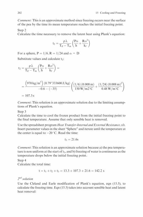
Comment: This is an approximate method since freezing occurs near the surface
of the pea by the time its mean temperature reaches the initial freezing point.
Step 2Calculate the time necessary to remove the latent heat using Plank’s equation:
t2 ¼r l
Tif � Tm
P�
hþR�2
kf
� �
For a sphere, P ¼ 1=6;R ¼ 1=24 and �= D
Substitute values and calculate t2:
t2 ¼r l
Tif � Tm
P�
hþR�2
kf
� �¼
¼970 kg=m3�
0:79�333600 J=kgð Þ�0:6� �35ð Þ
1=6ð Þ 0:008mð Þ150W=m28C
þ 1=24ð Þ 0:008mð Þ2
0:48W=m8C
!
¼ 107:3 s
Comment: This solution is an approximate solution due to the limiting assump-
tions of Plank’s equation.
Step 3Calculate the time to cool the frozen product from the initial freezing point tothe final temperature. Assume that only sensible heat is removed.
Use the spreadsheet programHeat Transfer-Internal and External Resistance.xls.
Insert parameter values in the sheet ‘‘Sphere’’ and iterate until the temperature at
the center is equal to �20 8C. Read the time:
t3 ¼ 21:6s
Comment: This solution is an approximate solution because a) the pea tempera-
ture is non uniform at the start of t3, and b) freezing of water is continuous as the
temperature drops below the initial freezing point.
Step 4Calculate the total time:
t ¼ t1 þ t2 þ t3 ¼ 13:3þ 107:3þ 21:6 ¼ 142:2 s
2nd solution
Use the Cleland and Earle modification of Plank’s equation, eqn (15.5), to
calculate the freezing time. Eqn (15.5) takes into account sensible heat and latent
heat removal:
202 15 Cooling and Freezing

t ¼ �H10
Tif � Tm
P�
hþR�2
kf
� �1� 1:65 Ste
kfln
Tc � Tm
�10� Tm
� �� �(15:5)
where �H10 is the volumetric enthalpy change of the food between the initialfreezing temperature and the final center temperature (assumed to be �10 8C).P and R are now functions of Ste (Stefan number) and Pk (Plank number):
Pk ¼ cu To � Tifð Þ�H10
Ste ¼ cf Tif � Tmð Þ�H10
Therefore it is necessary to calculate �H10, Pk, Ste, P, R, and finally t.
Step 1Calculate the volumetric enthalpy change �H10.
1) Calculate H at the initial freezing point using Schwartzberg’s equation.
i) Calculate the bound water.The bound water can be calculated as in Example 15.4 or alternatively by using
the relationship (Ref. 8):
xwb ¼ 0:4xp
where xp is the protein content of the food. In this case,
xwb ¼ 0:4�xp ¼ 0:4�0:0542 ¼ 0:0217
Comment: The bound water content calculated with this method is probably
too low.
ii) Calculate H:
H ¼ cf þ xwo � bxsð Þ �Ho
To � TR
To�Tif
To � T
� �� �T� TRð Þ¼
¼ ð1:76þ 0:79� 0:0217ð Þ 333:6
0� ð � 40Þ0� ð � 0:6Þ0� ð � 0:6Þ
� �� ��0:6� ð � 40Þð Þ¼
¼ 321:8 kJ=kg
Examples 203

2) Calculate H at �108C using Schwartzberg’s equation:
H ¼ cf þ xwo � bxsð Þ �Ho
To � TR
To�Tif
To � T
� �� �T� TRð Þ¼
¼ ð1:76þ 0:79� 0:0217ð Þ 333:6
0� ð � 40Þ0� ð � 0:6Þ0� ð � 10Þ
� �� ��10� ð � 40Þð Þ¼
¼ 64:3 kJ=kg
3) Therefore, the enthalpy difference between 0 8C and �10 8C is:
�H ¼ 321:8� 64:3 ¼ 257:5 kJ=kg
or the volumetric enthalpy difference is:
�H10 ¼ rf�H ¼ 970 kg=m3�
257:5 kJ=kgð Þ ¼ 249775 kJ=m3
Step 2Calculate Plank, Stefan and Biot numbers.
i) The volumetric heat capacity of the unfrozen product is:
cu ¼ rucu ¼ 1032 kg=m3� �
3:31 kJ=kg8Cð Þ ¼ 3415:9 kJ=m38C
ii) The volumetric heat capacity of the frozen product is:
cf ¼ rfcf ¼ 970 kg=m3� �
1:76 kJ=kg8Cð Þ ¼ 1707:2 kJ=m38C
iii) The Plank number is:
Pk ¼ cu To � Tifð Þ�H10
¼3415:9 kJ=m3 8C� �
15� �0:6ð Þð Þ8C249775 kJ=m3
¼ 0:213
iv) The Stefan number is:
Ste ¼ cf Tif � Tmð Þ�H10
¼1707:2 kJ=m3 8C� �
�0:6� �35ð Þð Þ8C249775 kJ=m3
¼ 0:235
204 15 Cooling and Freezing

v) The Biot number is:
Bi ¼ h D=2ð Þkf
¼ 150W=m28Cð Þ 0:004 mð Þ0:48 W=m8C
¼ 1:25
Step 3Calculate P and R from expressions for a sphere (see, e.g., Ref. 8):
P ¼ 0:1084þ 0:0924 Pkþ Ste 0:231 Pk� 0:1557
Biþ 0:6739
� �¼
¼ 0:1084þ 0:0924�0:213þ 0:235 0:231�0:213� 0:1557
1:25þ 0:6739
� �
¼0:269
R ¼ 0:0784þ Ste 0:0386 Pk� 0:1694ð Þ¼ 0:0784þ 0:235 0:0386�0:213� 0:1694ð Þ¼ 0:041
Step 4Substitute values in eqn (15.5) and calculate the time:
t ¼ �H10
Tif � Tm
PD
hþRD2
kf
� �1� 1:65 Ste
kfln
Tc � Tm
�10� Tm
� �� �¼
249775000 J=m3
�0:6� �35ð Þ8C0:269ð Þ 0:008mð Þ150W=m28C
þ 0:041ð Þ 0:008mð Þ2
0:48W=m8C
!�
� 1� 1:65�0:235
0:48W=m8Cln�20� �35ð Þ�10� �35ð Þ
� �� �¼ 203:2 s
3rd solution
Use the modification of Plank’s equation proposed by Pham to calculate the
freezing time for a slab, taking into account sensible heat and latent heat
removal, and then divide by the shape factor E to calculate the freezing time
for the sphere:
Examples 205

t ¼ 1
E
�H1
�T1þ�H2
�T2
� �P�
hþR�2
kf
� �(15:6)
with P ¼ 1=2;R ¼ 1=8, and �= characteristic dimension:
�H1 ¼ cu To � Tfmð Þ
�H2 ¼ lþ cf Tfm � Tcð Þ
cu and cf volumetric heat capacities and l volumetric latent heat of freezing:
�T1 ¼To þ Tfm
2� Tm
�T2 ¼ Tfm � Tm
Tfm ¼ 1:8þ 0:263Tc þ 0:105Tm
E ¼ 1þ1þ 2
Bi
b21 þ2b1
Bi
þ1þ 2
Bi
b22 þ2b2
Bi
b1 ¼A
pR2
b2 ¼V
43 pR
3b1
Therefore it is necessary to calculate �H1;�H2;�T1;�T2;Tfm;E; and finally t.
Step 1
1 Calculate �H1 and �H2:
i) The volumetric heat capacity of the unfrozen product is:
cu ¼ rucu ¼ 1032 kg=m3� �
3:31 kJ=kg8Cð Þ ¼ 3415:9 kJ=m38C
ii) The volumetric heat capacity of the frozen product is:
cf ¼ rf cf ¼ 970 kg=m3� �
1:76 kJ=kg8Cð Þ ¼ 1707:2 kJ=m38C
iii) The volumetric latent heat of freezing is:
l ¼ ðxwo � xwbÞr lw ¼ 0:79� 0:0217ð Þ 1032 kg=m3� �
333:6 kJ=kgð Þ¼ 264507 kJ=m3
206 15 Cooling and Freezing
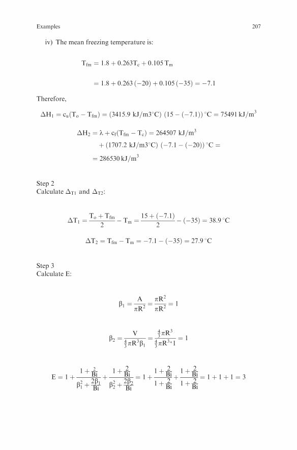
iv) The mean freezing temperature is:
Tfm ¼ 1:8þ 0:263Tc þ 0:105Tm
¼ 1:8þ 0:263 �20ð Þ þ 0:105 �35ð Þ ¼ �7:1
Therefore,
�H1 ¼ cu To � Tfmð Þ ¼ 3415:9 kJ=m38Cð Þ 15� �7:1ð Þð Þ 8C ¼ 75491 kJ=m3
�H2 ¼ lþ cf Tfm � Tcð Þ ¼ 264507 kJ=m3
þ 1707:2 kJ=m38Cð Þ �7:1� �20ð Þð Þ 8C ¼
¼ 286530 kJ=m3
Step 2Calculate �T1 and �T2:
�T1 ¼To þ Tfm
2� Tm ¼
15þ �7:1ð Þ2
� �35ð Þ ¼ 38:9 8C
�T2 ¼ Tfm � Tm ¼ �7:1� �35ð Þ ¼ 27:9 8C
Step 3Calculate E:
b1 ¼A
pR2¼ pR2
pR2¼ 1
b2 ¼V
43 pR
3b1¼
43 pR
3
43 pR
3�1¼ 1
E ¼ 1þ1þ 2
Bi
b21 þ2b1Bi
þ1þ 2
Bi
b22 þ2b2Bi
¼ 1þ1þ 2
Bi
1þ 2Bi
þ1þ 2
Bi
1þ 2Bi
¼ 1þ 1þ 1 ¼ 3
Examples 207
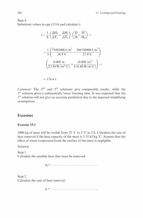
Step 4Substitute values in eqn (15.6) and calculate t:
t ¼ 1
E
�H1
�T1þ�H2
�T2
� �D
2hþD2
8kf
� �¼
¼ 1
3
75491000 J=m3
38:98Cþ 286530000 J=m3
27:98C
!
0:008 m
2 150W=m28Cð Þ þ0:008 mð Þ2
8 0:48W=m8Cð Þ
!¼
¼ 176:4 s
Comment: The 2nd and 3rd solutions give comparable results, while the
1st solution gives a substantially lower freezing time. It was expected that the
1st solution will not give an accurate prediction due to the imposed simplifying
assumptions.
Exercises
Exercise 15.1
1000 kg of meat will be cooled from 25 8C to 5 8C in 2 h. Calculate the rate of
heat removal if the heat capacity of the meat is 3.35 kJ/kg 8C. Assume that the
effect of water evaporated from the surface of the meat is negligible.
Solution
Step 1Calculate the sensible heat that must be removed:
qs¼ . . . . . . . . . . . . . . . . . . . . . . . . . . . . . . . . .
.Step 2Calculate the rate of heat removal:
q ¼ . . . . . . . . . . . . . . . . . . . . . . . . . . . . . . . . .
208 15 Cooling and Freezing

Exercise 15.2
1000 kg of unshelled green beans will be cooled from 25 8C to 58C in 2 h.Calculate the rate of heat removal if the heat capacity of beans is 3.35 kJ/kg 8C and the average heat of respiration between 5 and 25 8C is 0.2 W/kg.Assume that the effect of water evaporated from the surface of the beans isnegligible.
Solution
Step 1Calculate the sensible heat that must be removed:
qs¼ . . . . . . . . . . . . . . . . . . . . . . . . . . . . . . . . .
.
Step 2Calculate the heat of respiration:
qR¼ . . . . . . . . . . . . . . . . . . . . . . . . . . . . . . . . .
.
Step 3Calculate the total heat:
q ¼ . . . . . . . . . . . . . . . . . . . . . . . . . . . . . . . . .
.
Step 4Calculate the rate of heat removal:
q ¼ . . . . . . . . . . . . . . . . . . . . . . . . . . . . . . . . .
.
Exercise 15.3
To rapidly cool white wine grape musts for premium quality white wine pro-duction, dry ice is added to the must immediately after crushing the grapes.Calculate the amount of dry ice per kg of must required to cool the must from25 8C to 10 8C if the heat capacity of grapes is 3.6 kJ/kg 8C, the enthalpy of dryice is �31.9 kJ/kg and the enthalpy of CO2 gas at 10 8C and 1 atm pressure is380.9 kJ/kg.
Exercises 209

Solution
Step 1Draw the process diagram:
mg
HCO2 in
Hg in
mg
Hg outCRUSHER
mCO2
HCO2 outmCO2
Step 2Stateassumptions:. . .. . .. . .. . .. . .. . .. . .. . .. . .. . .. . .. . .. . .. . .. . .. . .. . .. . .. . .. . .. . .. . .
Step 3Write an enthalpy balance for the process and calculate mCO2:
mco2¼ . . . . . . . . . . . . . . . . . . . . . . . . . . . . . . . . . . . . . . . . . . . . . . . . . . .
Exercise 15.4
Calculate the time required to cool a rectangular piece of ham with dimen-
sions 0.1 m � 0.1 m � 0.3 m in a refrigerator from 60 8C to 5 8C if the air
temperature in the refrigerator is 1 8C, the heat transfer coefficient in the
refrigerator is 10 W/m2 8C, the density of the ham is 1080 kg/m3, the thermal
conductivity is 0.38 W/m 8C, and the heat capacity is 3750 J/kg 8C.
Solution
Step 1Calculate the Biot number for the x, y, and z directions:
Bix ¼ . . . . . . . . . . . . . . . . . . . . . . . . . . . . . . . . .
Biy ¼ . . . . . . . . . . . . . . . . . . . . . . . . . . . . . . . . .
Biz¼ . . . . . . . . . . . . . . . . . . . . . . . . . . . . . . . . .
210 15 Cooling and Freezing

Step 2Use the spreadsheet programHeat Transfer-Internal and External Resistance.xlsorHeat Transfer-Negligible External Resistance.xls (depending on theBi values).Read the instructions, insert parameter values, and iterate until the massaverage temperature is equal to 5 8C. Read the time.
Exercise 15.5
Calculate the ice fraction and the unfrozen water fraction in salmon at�20 8C if
the initial freezing point is �2.2 8C, the moisture content of the unfrozen fish is
76.4%, and b = 0.25 kg water/kg solids. Test the sensitivity of the ice fraction
and the unfrozen water fraction on the value of the temperature and b.
Solution
Use the spreadsheet program Ice fraction.xls to calculate the ice fraction and the
unfrozen water fraction.Run the program for different b values and different T values and see how the
ice fraction and the unfrozen water fraction are affected.
Exercise 15.6
Calculate the heat that is removed when 1000 kg cod is frozen from 5 8C to
�26 8C, the recommended temperature for frozen fish storage, if the moisture
content of the unfrozen fish is 80.3%, the initial freezing point is �2.2 8C, theheat capacity of the unfrozen fish is 3.77 kJ/kg 8C, the heat capacity of the fullyfrozen fish is 2.0 kJ/kg 8C, and 0.3 kg water are bound per kg solid.
Solution
Step 1Calculate the enthalpy of fish at 5 8C with Schwartzberg’s equation, using�40 8C as reference temperature:
H ¼ cpu T� Tifð Þ þ cf þ xwo � bxsð Þ �Ho
To � TR
� �� �Tif � TRð Þ ¼
¼ . . . . . . . . . . . . . . . . . . . . . . . . . . . . . . . . . . . . . . . . . . . . . . . . . . . . . . . . . . . . . . . . . .
Step 2Calculate the enthalpy of fish at -26 8C using Schwartzberg’s equation:
H ¼ cf þ xwo � bxsð Þ DHo
To � TR
To�Tif
To � T
� �� �T� TRð Þ ¼
¼ . . . . . . . . . . . . . . . . . . . . . . . . . . . . . . . . . . . . . . . . . . . . . . . . . . . . . . . . . . . . . . . . . .
Exercises 211
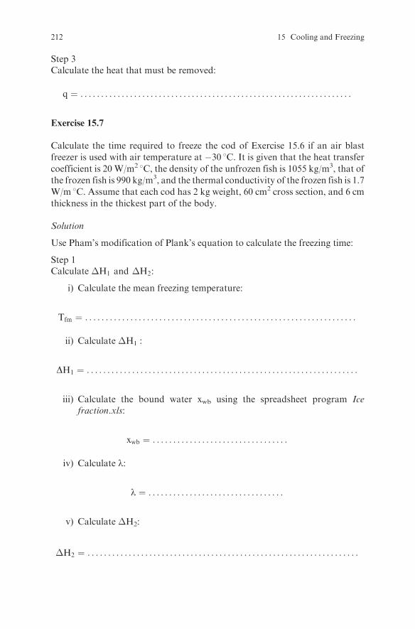
Step 3Calculate the heat that must be removed:
q ¼ . . . . . . . . . . . . . . . . . . . . . . . . . . . . . . . . . . . . . . . . . . . . . . . . . . . . . . . . . . . . . . . . . .
Exercise 15.7
Calculate the time required to freeze the cod of Exercise 15.6 if an air blast
freezer is used with air temperature at �30 8C. It is given that the heat transfer
coefficient is 20 W/m2 8C, the density of the unfrozen fish is 1055 kg/m3, that of
the frozen fish is 990 kg/m3, and the thermal conductivity of the frozen fish is 1.7
W/m 8C. Assume that each cod has 2 kg weight, 60 cm2 cross section, and 6 cm
thickness in the thickest part of the body.
Solution
Use Pham’s modification of Plank’s equation to calculate the freezing time:
Step 1Calculate �H1 and �H2:
i) Calculate the mean freezing temperature:
Tfm ¼ . . . . . . . . . . . . . . . . . . . . . . . . . . . . . . . . . . . . . . . . . . . . . . . . . . . . . . . . . . . . . . . . . .
ii) Calculate �H1 :
DH1 ¼ . . . . . . . . . . . . . . . . . . . . . . . . . . . . . . . . . . . . . . . . . . . . . . . . . . . . . . . . . . . . . . . . . .
iii) Calculate the bound water xwb using the spreadsheet program Icefraction.xls:
xwb ¼ . . . . . . . . . . . . . . . . . . . . . . . . . . . . . . . . .
iv) Calculate l:
l ¼ . . . . . . . . . . . . . . . . . . . . . . . . . . . . . . . . .
v) Calculate �H2:
�H2 ¼ . . . . . . . . . . . . . . . . . . . . . . . . . . . . . . . . . . . . . . . . . . . . . . . . . . . . . . . . . . . . . . . . . .
212 15 Cooling and Freezing

Step 2Calculate �T1 and �T2:
�T1¼ . . . . . . . . . . . . . . . . . . . . . . . . . . . . . . . . .
�T2 ¼ . . . . . . . . . . . . . . . . . . . . . . . . . . . . . . . . .
Step 3Calculate E using R as the characteristic dimension and A as the cross sectionthrough the thickest part of the fish (Ref. 10):
2R
A
i) Calculate b1 ¼ . . . . . . . . . . . . . . . . . . . . . . . . . . . . . . . . .
ii) Calculate b2 using V equal to the volume of the fish:
b2 ¼ . . . . . . . . . . . . . . . . . . . . . . . . . . . . . . . . .
iii) Calculate Bi:
Bi ¼ hR
kf¼ . . . . . . . . . . . . . . . . . . . . . . . . . . . . . . . . .
iv) Calculate the shape factor E:
E ¼ :::::::::::::::::::::::::::::::::::::::::::::::::::::::::::::::::::::::::::::::::::::::::::::::
Step 4Calculate the time:
t ¼ ::::::::::::::::::::::::::::::::::::::::::::::::::::::::::::::::::::::::::::::::::::::::::::::::::
Exercise 15.8
Calculate the required compressor power in Exercise 15.7 if the evaporatortemperature is �40 8C, the condenser temperature is 40 8C, the refrigerationunit uses refrigerant 404A at saturation conditions with compressor efficiency
Exercises 213

equal to 0.85 and the product cooling load represents 80% of the total heatremoval load.
Solution
Step 1Find the enthalpy of the refrigerant before and after the evaporator and thecompressor from the pressure-enthalpy chart of refrigerant 404A or from atable with pressure enthalpy values for 404A.
Step 2Calculate the heat absorption rate in the evaporator. Take into account that theproduct cooling load is 80% of the total load.
Step 3Calculate the compressor power.
Exercise 15.9
Rectangular pieces of ground meat with dimensions 5 cm x 5 cm x 20 cm areplaced in a batch freezer. The initial temperature of the meat is 5 8C, the initialfreezing point is�2.2 8C, the moisture content is 73%, the bound water fractionis 0.05, the heat capacity is 2.9 kJ/kg 8C and 1.4 kJ/kg 8C for the unfrozenproduct and the fully frozen product respectively, the thermal conductivity is0.5 W/m 8C and 1.3 W/m 8C for the unfrozen product and the fully frozenproduct respectively, the density is 1045 kg/m3 and 1030 kg/m3 for the unfrozenand the frozen product respectively. The heat transfer coefficient is equal to10 W/m2 8C. The air temperature in the freezer varies due to the ON-OFFoperation of the compressor according to the relationship T = AþBsin(2pNt)with A=�20 8C, B= 2 8C and N= 2 h�1. Calculate and plot the temperatureat the center of a piece of meat with time until it reaches �20 8C.
Solution
Since the length of the pieces of meat is much higher than the other twodimensions, it can be assumed that the heat transfer will be in two dimensionsonly.Use the spreadsheet program Freezing temperature 2D.xls to calculate andplot the temperature. Read the instructions; run the program until the tempera-ture in the center is equal to �20 8C. Read the time necessary to freeze theproduct to �20 8C. Observe the freezing curve for the center and the corner.
Turn the SWITCH OFF; change the bound water value to 0.08; run theprogram again; compare the results with the previous case.
Turn the SWITCH OFF; change the heat transfer coefficient value to 30 W/m2 8C; run the program again; compare the time to reach �20 8C in the centerwith the previous case; compare the freezing curves; observe the temperaturefluctuation in the product after the center temperature reaches �20 8C; compareit with the previous cases; explain the results.
214 15 Cooling and Freezing
Chapter 16
Evaporation
Review Questions
Which of the following statements are true and which are false?
1. Evaporation is used to decrease the weight and volume of a liquid product.2. Concentration of a liquid food increases the shelf life of the food since it
decreases the water activity.3. Falling film evaporators are not suitable for heat sensitive products.4. Agitated film evaporators are suitable for viscous liquids.5. Fruit juices are concentrated in falling film evaporators.6. Gelatin is concentrated in agitated film evaporators.7. Milk is concentrated in short tube vertical evaporators.8. Tomato juice is concentrated in forced-circulation evaporators.9. Falling film tube evaporators are more compact than plate evaporators.
10. Natural circulation evaporators are suitable for heat sensitive liquid foods.11. Natural circulation evaporators are not suitable for viscous liquids.12. Forced circulation evaporators are suitable for viscous liquid foods.13. Rising film evaporators require smaller temperature differences than falling
film evaporators.14. Rising film evaporators are short tube evaporators.15. Falling film evaporators are long tube evaporators.16. Backward feed evaporators are suitable for highly viscous liquid foods.17. Backward feed evaporators are suitable when the fresh feed is cold.18. Boiling under vacuum decreases the heat damage to heat sensitive products.19. Multiple effect evaporators reuse the latent heat of vapor and thus save energy.20. The overall temperature difference in a multiple effect evaporator will
increase if the pressure in the last effect increases, while steam pressure inthe first effect remains unchanged.
21. The concentration of the final product will increase if the overall tempera-ture difference in an evaporator is increased.
22. If the cooling water temperature in the condenser is decreased, the finalproduct concentration will increase.
23. If the feed flow rate is increased, the final product concentrationwill increase.
S. Yanniotis, Solving Problems in Food Engineering.� Springer 2008
215

24. If the steam temperature is increased, the final product concentration willincrease.
25. Duhring line plots are plots of the boiling point of a solution vs. the boilingpoint of pure water at the same pressure.
26. Boiling point elevation results in a decrease of the available temperaturedifference.
27. The hydrostatic head in rising film evaporators reduces the available tem-perature difference.
28. Residence time in a falling film evaporator is smaller than in a forcedcirculation evaporator.
29. Centrifugal evaporators have a residence time in the heating zone of a fewseconds.
30. The residence time in a forced circulation evaporator is high.31. The overall heat transfer coefficient decreases as the concentration of the
product increases.32. Overall heat transfer coefficients up to 2500 W/m2K are usually encoun-
tered in the first effect of a falling film evaporator.33. Fouling of the evaporator tubes reduces its capacity.34. Preheating the feed to the boiling point of the first effect reduces the heat
transfer area needed.35. The use of high pressure steam in the first effect decreases the size and the
cost of the evaporator, but steam temperature is limited by product qualityconsiderations.
36. Last effect pressure is limited by coolingwater temperature in the condenser.37. At steady state, pressure and temperature in the intermediate effects are
automatically adjusted by the process itself.38. A liquid vapor separator is not necessary in a forced circulation evaporator.39. A barometric leg may be used with the condenser to make easier the exit of
condensate.40. A steam jet may be used to remove noncondensables from an evaporator.41. A vacuum pump is used to remove the vapor produced in the last effect.42. A height of about 6 m is used in the leg of a barometric condenser.43. Noncondensables in the steam chest decrease the condensation rate and the
condensation temperature.44. Approximately one kg of water is evaporated per kg of steam consumed in
the first effect of a multiple effect evaporator.45. Steam economy is defined as the ratio of steam consumption to the amount
of water evaporated.46. Condensate reuse may be used as a measure for energy conservation.47. Fouling or scaling of the heat transfer surface may decrease steam
economy.48. Excess steam venting to keep noncondensables at a low level increases
energy consumption.49. A typical steam economy for a four-effect evaporator without vapor recom-
pression is 4.3.
216 16 Evaporation
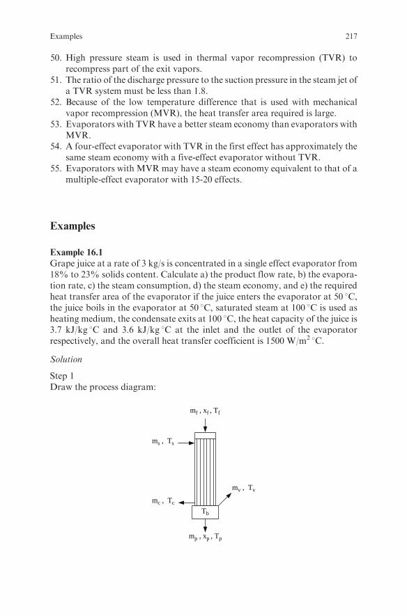
50. High pressure steam is used in thermal vapor recompression (TVR) torecompress part of the exit vapors.
51. The ratio of the discharge pressure to the suction pressure in the steam jet ofa TVR system must be less than 1.8.
52. Because of the low temperature difference that is used with mechanicalvapor recompression (MVR), the heat transfer area required is large.
53. Evaporators with TVR have a better steam economy than evaporators withMVR.
54. A four-effect evaporator with TVR in the first effect has approximately thesame steam economy with a five-effect evaporator without TVR.
55. Evaporators with MVR may have a steam economy equivalent to that of amultiple-effect evaporator with 15-20 effects.
Examples
Example 16.1
Grape juice at a rate of 3 kg/s is concentrated in a single effect evaporator from18% to 23% solids content. Calculate a) the product flow rate, b) the evapora-tion rate, c) the steam consumption, d) the steam economy, and e) the requiredheat transfer area of the evaporator if the juice enters the evaporator at 50 8C,the juice boils in the evaporator at 50 8C, saturated steam at 100 8C is used asheating medium, the condensate exits at 100 8C, the heat capacity of the juice is3.7 kJ/kg 8C and 3.6 kJ/kg 8C at the inlet and the outlet of the evaporatorrespectively, and the overall heat transfer coefficient is 1500 W/m2 8C.
Solution
Step 1Draw the process diagram:
mf , xf , Tf
ms , Ts
mv , Tv
mc , TcTb
mp , xp , Tp
Examples 217
where mf, xf, Tf are the mass flow rate, solids content and temperature for thefeed;mp, xp, and Tp are themass flow rate, solids content, and temperature for
the product;ms, Ts are the mass flow rate and temperature for the steam;mc, Tc are the mass flow rate and temperature for the condensate;mv, Tv are the mass flow rate and temperature for the vapor produced;andTb is the boiling temperature.
Step 2State your assumptions:
l Heat losses to the environment are neglected.l The boiling point elevation of the juice is negligible.l The evaporator operates at steady state.
Step 3Calculate the product flow rate from a solids mass balance:
mfxf ¼ mpxp
or
mp ¼mfxfxp¼ 3 kg=sð Þ 0:18ð Þ
0:23¼ 2:348 kg=s
Step 4Calculate the evaporation rate from a mass balance:
mf ¼ mp þmv
and
mv ¼ mf �mp ¼ 3 kg=s� 2:348 kg=s ¼ 0:652 kg=s
Step 5Calculate the steam consumption from an enthalpy balance:
mfHf þmsHs ¼ mpHp þmcHc þmvHv
Because the steam flow rate is equal to the condensate flow rate ms ¼ mcð Þ andthe difference between the enthalpy of saturated steam and the enthalpy ofcondensate is equal to the latent heat of condensation Hs �Hc ¼ lsð Þ, theabove equation becomes:
msls ¼ mpHp �mfHf þmvHv
218 16 Evaporation

Solve for ms:
ms ¼mpHp �mfHf þmvHv
ls
Using 0 8C as a reference temperature, the enthalpy of the liquid streams is:
H ¼ cpT
The enthalpy of saturated steam, saturated vapor, and condensate is found fromsteam tables:
Hs at 100 8C ¼ 2676 kJ=kg
Hc at 100 8C ¼ 419 kJ=kg
ls at 100 8C ¼ 2676� 419 ¼ 2257 kJ=kg
Hv at 50 8C ¼ 2592 kJ=kg
Therefore:
ms ¼mpHp �mfHf þmvHv
ls¼ mpcppTp �mfcpfTf þmvHv
ls¼
¼ 2:348 kg=sð Þ 3600 J=kg 8Cð Þ 50 8Cð Þ � 3 kg=sð Þ 3700 J=kg 8Cð Þ 50 8Cð Þ2257000 J=kg
þ
þ 0:652 kg=sð Þ 2592000 J=kgð Þ2257000 J=kg
¼ 0:690 kg=s
Step 6Calculate the steam economy:
steam economy ¼ mv
ms¼ 0:652 kg=s
0:690 kg=s¼ 0:945
kgwater evaporated
kg of steam
Step 7Calculate the heat transfer area of the evaporator:
i) Write the heat transfer rate equation:
q ¼ AU Ts � Tbð Þ
ii) Write an enthalpy balance on the steam side of the evaporator:
q ¼ msHs �mcHc ¼ msls
iii) Combine the last two equations:
msls ¼ AU Ts � Tbð Þ
Examples 219
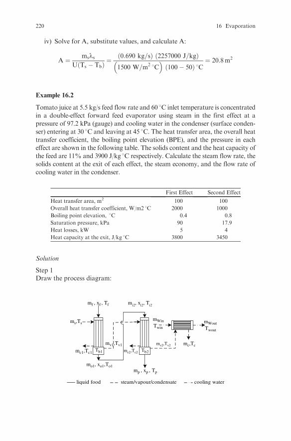
iv) Solve for A, substitute values, and calculate A:
A ¼ mslsU Ts � Tbð Þ ¼
0:690 kg=sð Þ 2257000 J=kgð Þ1500 W=m2 8C� �
100� 50ð Þ 8C¼ 20:8m2
Example 16.2
Tomato juice at 5.5 kg/s feed flow rate and 60 8C inlet temperature is concentrated
in a double-effect forward feed evaporator using steam in the first effect at a
pressure of 97.2 kPa (gauge) and cooling water in the condenser (surface conden-
ser) entering at 30 8C and leaving at 45 8C. The heat transfer area, the overall heattransfer coefficient, the boiling point elevation (BPE), and the pressure in each
effect are shown in the following table. The solids content and the heat capacity of
the feed are 11% and 3900 J/kg 8C respectively. Calculate the steam flow rate, the
solids content at the exit of each effect, the steam economy, and the flow rate of
cooling water in the condenser.
First Effect Second Effect
Heat transfer area, m2 100 100
Overall heat transfer coefficient, W/m2 8C 2000 1000
Boiling point elevation, 8C 0.4 0.8
Saturation pressure, kPa 90 17.9
Heat losses, kW 5 4
Heat capacity at the exit, J/kg 8C 3800 3450
Solution
Step 1Draw the process diagram:
steam/vapour/condensate cooling waterliquid food
mf , xf , Tf
ms,Ts
mv1,Tv1 mv2,Tv2
mc2,Tc2mc1,Tc1
mWinTwin
mWoutTwout
mc,Tc
mi2, xi2, Ti2
mo1, xo1,To1
Tb1 Tb2
mp , xp , Tp
220 16 Evaporation

Step 2State your assumptions:
l The condensate in each effect exits at the condensation temperature.l The operation is steady state.
Step 3Combine the heat transfer rate equation with an enthalpy balance in the firsteffect, as in step 7 of Exercise 16.1, to calculate the steam consumption:
q ¼ msHs �mc1Hc1 ¼ A1U1 Ts � Tb1ð Þ (16:1)
Because the condensate was assumed to exit at the condensation temperature,Hs �Hc1 ¼ ls= the latent heat of condensation at 120 8C (97.2 kPa gaugepressure corresponds to 198.5 kPa absolute pressure or 120 8C saturationtemperature in the steam chest of the first effect). Also ms ¼ mc1. Thereforeeqn (16.1) becomes:
msls ¼ A1U1 Ts � Tb1ð Þ (16:2)
with
Hs at 120 8C ¼ 2706 kJ=kgðfrom Steam tablesÞ
Hcl at 120 8C ¼ 504 kJ=kgðfrom Steam tablesÞ
ls at 120 8C ¼ 2706� 504 ¼ 2202 kJ=kg
The saturation temperature in the 1st effect, Tsat1, is found from steam tables forPsat = 90 kPa to be equal to 96.6 8C. Therefore, the boiling temperature in the
1st effect, Tb1, is:
Tb1 ¼ Tsat1 þ BPE1 ¼ 96:6þ 0:4 ¼ 97 8C (16:3)
Solve eqn (16.2) for ms, substitute values, and calculate ms:
ms ¼A1U1 Ts � Tb1ð Þ
ls¼
100m2� �
2000W=m28C� �
120� 97ð Þ 8C2202000 J=kg
¼ 2:089 kg=s
Step 4Calculate the solids content:
1) At the exit of the first effect:
i) Write an enthalpy balance around the first effect:
mfHf þmsHs ¼ mo1Ho1 þmc1Hc1 þmv1Hv1 þ qloss 1 (16:5)
Examples 221
ii) Analyze the terms of eqn (16.5):
a) Find Hv1:The vapor exiting from the first effect is slightly superheated due to theBPE of the juice. Thus:
Hv1 ¼ Hv1 saturated þ cp vapourBPE
Because the BPE is small, Hv1 can be assumed equal to the enthalpy of
saturated steam, Hv1 saturated. Thus:
Hv1at96:6 8C ¼ 2671kJ=kgðfrom Steam tablesÞ
b) Find mv1:A mass balance on the product gives:
mf ¼ mo1 þmv1
or
mv1 ¼ mf �mo1 (16:6)
c) Find the enthalpy of liquid streams:Using 0 8C as a reference temperature, the enthalpy of the liquid streamsis:
H ¼ cpT (16:7)
iii) Substitute eqns (16.6) and (16.7) in eqn (16.5):
mfcp fTf þmsHs ¼ mo1cpo1To1 þmc1Hc1 þ mf �mo1ð ÞHv1 þ qloss 1 (16:8)
iv) Solve eqn (16.8) for mo1, substitute values, and calculate the mass flow
rate at the exit of the first effect:
mo1 ¼mfcp fTf þmsls �mfHv1 � qloss 1
cp o1To1 �Hv1¼ 5:5 kg=sð Þ 3900 J=kg 8Cð Þ 60 8Cð Þ
3800 J=kg8Cð Þ 97 8Cð Þ�2671000 J=kg
þ 2:089 kg=sð Þ 2202000 J=kgð Þ � 5:5 kg=sð Þ 2671000 J=kgð Þ � 5000W
3800 J=kg 8Cð Þ 97 8Cð Þ � 2671000 J=kg
¼ 3:826 kg=s
v) Calculate the solids content at the exit of the first effect from a solids massbalance:
mfxf ¼ mo1xo1 (16:9)
222 16 Evaporation
Solve eqn (16.9) for xo1, substitute values, and calculate xo1:
xo1 ¼mfxfmo1
¼ 5:5 kg=sð Þ 0:11ð Þ3:826 kg=s
¼ 0:158
2) At the exit of the second effect:
i) Write an enthalpy balance around the second effect:
mi2Hi2 þmv1Hv1 ¼ mpHp þmc2Hc2 þmv2Hv2 þ qloss 2 (16:10)
ii) Analyze the terms of eqn (16.10):
mi2 ¼ mo1 ¼ 3:826 kg=s;
mv1 ¼ mf �m01 ¼ 5:5� 3:826 ¼ 1:674 kg=s;
mc2 ¼ mv1 ¼ 1:674 kg=s;
Hi2 ¼ Ho1 ¼ cp o1To1 ¼ 3800 J=kg 8Cð Þ 97 8Cð Þ ¼ 368600 J=kg;
Hv1 ¼ 2671 kJ=kgðfrom steam tablesÞ
Hc2 at 96:6 8C ¼ 405 kJ=kgðfrom steam tablesÞ
The saturation temperature in the second effect, Tsat2, is foundfrom steam tables for Psat = 17.9 kPa to be equal to 57.6 8C.Therefore, the boiling temperature in the second effect, Tb2, is:
Tb2 ¼ Tsat2 þ BPE2 ¼ 57:6þ 0:8 ¼ 58:4 8C
The enthalpy, Hv2 (neglecting the enthalpy of superheating), is:
Hv2 at 57:6 8C ¼ 2605 kJ=kgðfrom steam tablesÞ
Write a mass balance on the product to calculate mv2:
mi2 ¼ mp þmv2
Solve for mv2
mv2 ¼ mi2 �mp (16:11)
iii) Substitute eqn (16.11) in eqn (16.10):
mi2Hi2 þmv1Hv1 ¼ mpcppTp þmc2Hc2 þ mi2 �mp
� �Hv2 þ qloss 2 (16:12)
Examples 223

iv) Solve eqn (16.12) for mp and substitute values:
mp ¼mi2Hi2 þmv1Hv1 �mc2Hc2 �mi2Hv2 � qloss 2
cppTp �Hv2¼
¼ 3:826 kg=sð Þ ð368600 J=kgÞ þ 1:674 kg=sð Þ 2671000 � 405000 J=kgð Þ3450 J=kg 8Cð Þ 58:4 8Cð Þ � 2605000 J=kg
� 3:826 kg=sð Þ 2605000 J=kgð Þ � 4000 J=s
3450 J=kg 8Cð Þ 58:4 8Cð Þ � 2605000 J=kg¼ 1:983 kg=s
v) Substitute values in eqn (16.11) and calculate the evaporation rate in thesecond effect:
mv2 ¼ mi2 �mp ¼ 3:826� 1:983 ¼ 1:843 kg=s
vi) Calculate the solids content at the exit of the second effect from a solidsmass balance:
mfixi2 ¼ mpxp
Solve for xp, substitute values, and calculate xp:
xp ¼mi2xi2mp
¼ 3:826 kg=sð Þ 0:158ð Þ1:983 kg=s
¼ 0:305
Step 5Calculate the steam economy:
steam economy ¼ mv1 þmv2
ms¼ 1:674þ 1:843
2:089
¼ 1:68kg water evaporated
kg steam
Step 6Calculate the cooling water flow rate in the condenser:
i) Write an enthalpy balance in the condenser:
mw inHw in þmv2Hv2 ¼ mwoutHwout þmcHc
or
mw incpw inTw in þmv2Hv2 ¼ mwoutcpwoutTwout þmcHc(16:13)
with
224 16 Evaporation
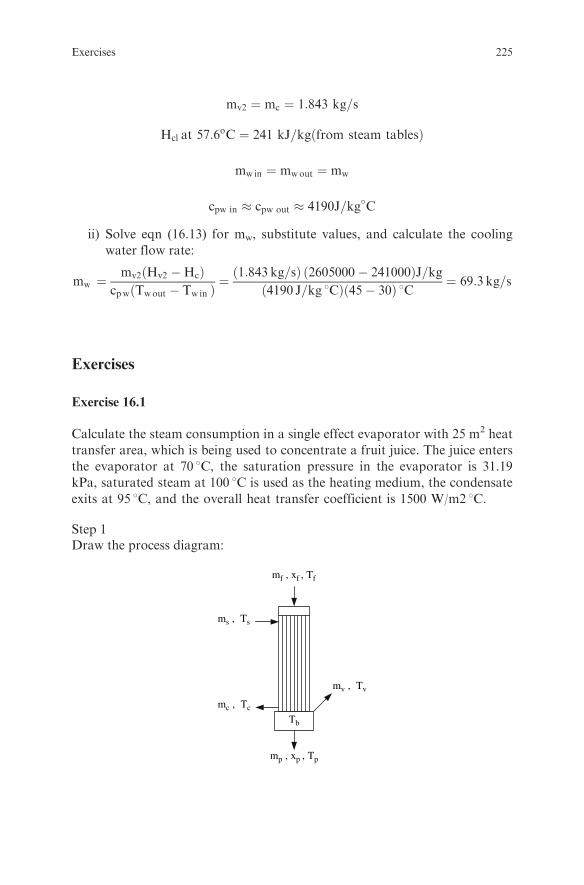
mv2 ¼ mc ¼ 1:843 kg=s
Hcl at 57:6oC ¼ 241 kJ=kgðfrom steam tablesÞ
mwin ¼ mwout ¼ mw
cpw in � cpw out � 4190J=kg�C
ii) Solve eqn (16.13) for mw, substitute values, and calculate the cooling
water flow rate:
mw ¼mv2 Hv2 �Hcð Þ
cpw Twout � Tw inð Þ ¼1:843 kg=sð Þ 2605000� 241000ð ÞJ=kg
4190 J=kg 8Cð Þ 45� 30ð Þ 8C ¼ 69:3 kg=s
Exercises
Exercise 16.1
Calculate the steam consumption in a single effect evaporator with 25 m2 heat
transfer area, which is being used to concentrate a fruit juice. The juice enters
the evaporator at 70 8C, the saturation pressure in the evaporator is 31.19
kPa, saturated steam at 100 8C is used as the heating medium, the condensate
exits at 95 8C, and the overall heat transfer coefficient is 1500 W/m2 8C.
Step 1Draw the process diagram:
mf , xf , Tf
ms , Ts
mv , Tv
mc , Tc
Tb
mp , xp , Tp
Exercises 225

Step 2State your assumptions:
l The boiling point elevation is negligible.l The heat losses to the environment are negligible.l The system operates at steady state.
Step 3Write the heat transfer rate equation:
:::::::::::::::::::::::::::::::::::::::::::::::::::::::::: (16:14)
Step 4Write an enthalpy balance on the steam side:
::::::::::::::::::::::::::::::::::::::::::::::::::::::::: (16:15)
Step 5Combine eqns (16.14) and (16.15) and calculate the steam consumption:
ms ¼ ::::::::::::::::::::::::::::::::::::::::::::::::::::::::::::::::::::::::::::::::::::::::::::::::::
Exercise 16.2
Calculate the steam consumption and the steam economy in a single effect
evaporator which is being used to concentrate a fruit juice. The juice enters
the evaporator at 25 8C and a feed flow rate of 2 kg/s, the saturation pressure
in the evaporator is 31.19 kPa, saturated steam at a pressure of 143.27 kPa is
used as heating medium, the condensate exits at the steam condensation
temperature, the heat capacity of the juice is 3.9 kJ/kg 8C and 3.7 kJ/kg 8Cat the inlet and the outlet of the evaporator respectively, and the solids
content is 10% and 20% at the inlet and the outlet of the evaporator
respectively.
Solution
Step 1Draw the process diagram:
226 16 Evaporation

mf , xf , Tf
ms , Ts
mv , Tv
mc , TcTb
mp , xp , Tp
Step 2State your assumptions:
::::::::::::::::::::::::::::::::::
Step 3Write a solids mass balance to calculate the outlet flow rate:
mp ¼ ::::::::::::::::::::::::::::::::::::::::::::::::::::::::::::::::::::::
Step 4Write an enthalpy balance around the effect:
mfHf þmsHs ¼ ::::::::::::::::::::::::::::::::::::::::::::::::::::::::::::::::::::::::::::::: (16:16)
Find:
Hv at 31:19 kPa ¼ :::::::::::::::::::::::::::::::::kJ=kg
Hs at 143:27 kPa ¼ :::::::::::::::::::::::::::::::::kJ=kg
Hc at 143:27 kPa ¼ :::::::::::::::::::::::::::::::::kJ=kg
Solve eqn (16.16) for ms, substitute values, and calculate ms:
ms ¼ ::::::::::::::::::::::::::::::::::::::::::::::::::::::::::::::::::::::::::::::::::::::::::::::::::::::::::::
Step 5Calculate the steam economy:
steam economy ¼ ::::::::::::::::::::::::::::::::::::::::::::::::::::::::::::::::::::
Exercises 227
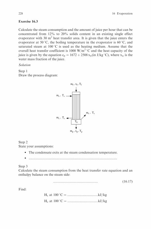
Exercise 16.3
Calculate the steam consumption and the amount of juice per hour that can be
concentrated from 12% to 20% solids content in an existing single effect
evaporator with 30 m2 heat transfer area. It is given that the juice enters the
evaporator at 50 8C, the boiling temperature in the evaporator is 60 8C, andsaturated steam at 100 8C is used as the heating medium. Assume that the
overall heat transfer coefficient is 1000 W/m2 8C and the heat capacity of the
juice is given by the equation cp ¼ 1672þ 2508 xw(in J/kg 8C), where xw is the
water mass fraction of the juice.
Solution
Step 1Draw the process diagram:
mf , xf , Tf
ms , Ts
mv , Tv
mc , Tc
Tb
mp , xp , Tp
Step 2State your assumptions:
l The condensate exits at the steam condensation temperature.
l ...............................................................................................
Step 3Calculate the steam consumption from the heat transfer rate equation and anenthalpy balance on the steam side:
:::::::::::::::::::::::::::::::::::::::::::::::: (16:17)
Find:
Hs at 100 8C ¼ :::::::::::::::::::::::::::::::::kJ=kg
Hc at 100 8C ¼ :::::::::::::::::::::::::::::::::kJ=kg
228 16 Evaporation

Solve eqn (16.17) for ms, substitute values, and calculate the steam consump-tion:
ms ¼ ::::::::::::::::::::::::::::::::::::::::::::::::::::::::::::::::::::::::::::::::::::::::::::::::::
Step 4Calculate the feed flow rate, mf:
i) Express mp as a function of mf from a solids mass balance:
mp ¼ ::::::::::::::::::::::::::::::::::::::::::::::::::::::: (16:18)
ii) Write an enthalpy balance around the effect:
mfcpfTf þ ::::::::::::::::::::::::::::::::::::::::::::::::::::::::::::::::::::::::::::::::::::::: (16:19)
iii) Substitute mp from eqn (16.18) in eqn (16.19):
mfcpfTf þ ::::::::::::::::::::::::::::::::::::::::::::::::::::::::::::::::::::::::::::::::::::: (16:20)
iv) Find:
Hv at 60 8C ¼ :::::::::::::::::::::::::::::::::kJ=kg
cpf ¼ :::::::::::::::::::::::::::::::::::::::::::::::::::::::::::::::::::::::::::::::::::::::::::J=kg 8C
cpp ¼ ::::::::::::::::::::::::::::::::::::::::::::::::::::::::::::::::::::::::::::::::::::::::::::J=kg 8C
v) Solve eqn (16.20) for mf, substitute values, and calculate mf:
mf ¼ ::::::::::::::::::::::::::::::::::::::::::::::::::::::::::::::::::::::::::::::::::::::::::::::::::::::::::::
Exercise 16.4
A fruit juice is concentrated from 10% to 30% solids content in a double-effect
forward-feed evaporator at a flow rate of 10000 kg/h. The temperature of the
juice at the inlet is 70 8C and the steam temperature is 110 8C. The cooling watertemperature at the inlet of the condenser (surface condenser) is 25 8C and at the
outlet 42 8C. The heat capacity of the juice at the inlet of the evaporator is 3.9
kJ/kg 8C. Calculate the evaporation rate in each effect, the steam economy, and
Exercises 229

the cooling water flow rate in the condenser. The heat capacity at the exit of
each effect and the boiling temperature are given in the following table:
First Effect Second Effect Condenser
Heat capacity at the exit, J/kg 8C 3800 3400 4190
Boiling temperature, 8C 87 55
Solution
Step 1Draw the process diagram:
steam/vapour/condensate cooling waterliquid food
mf , xf , Tf
ms,Ts
mv1,Tv1 mv2,Tv2
mc2,Tc2mc1,Tc1
mWinTwin
mWoutTwout
mc,Tc
mi2, xi2, Ti2
mo1, xo1,To1
Tb1 Tb2
mp , xp , Tp
Step 2State your assumptions:
:::::::::::::::::::::::::::::::::::::::::::::::::::::::::::::::::::::::::::::::::::::::::::::::::::::::::::::::::::::
Step 3Calculate the evaporation rate.
i) Write a solids mass balance to calculate the outlet flow rate from the firsteffect:
mp ¼ :::::::::::::::::::::::::::::::::::::::::::::::::::::::::::::::::::::: (16:21)
ii) Write an enthalpy balance around the second effect to calculate the flowrate at the inlet of the second effect mi2, taking into account thatmi2 ¼ mo1:
mi2Hi2 þmv1Hv1 ¼ ::::::::::::::::::::::::::::::::::::::::::::::::::::::::::::::::::::: (16:22)
230 16 Evaporation

Find:
Hv at 87 8C ¼ :::::::::::::::::::::::::::::::::kJ=kg
Hv at 55 8C ¼ ::::::::::::::::::::::::::::::::::kJ=kg
Hc at 87 8C ¼ :::::::::::::::::::::::::::::::::kJ=kg
Hc at 55 8C ¼ ::::::::::::::::::::::::::::::::::kJ=kg
iii) Write amass balance on the liquid food side in the first effect to calculate theevaporation rate in the first effect:
mv1 ¼ :::::::::::::::::::::::::::::::::::::::::::::::::::::::::::::::::::::::::::::: (16:23)
iv) Write a mass balance on the liquid food side in the second effect to calculatethe evaporation rate in the second effect:
mv2 ¼ :::::::::::::::::::::::::::::::::::::::::::::::::::::::::::::::::::::::::::::: (16:24)
v) Combine eqns (16.22), (16.23) and (16.24) and solve for mo1
mo1 ¼ ::::::::::::::::::::::::::::::::::::::::::::::::::::::::::::::::::::::::::::::
Step 4Calculate the steam economy:
i) Write an enthalpy balance around the first effect to calculate the steam flowrate in the first effect, ms:
mfHf þmsHs ¼ :::::::::::::::::::::::::::::::::::::::::::::::::::::::::::::::::::::::::::::::::::: (16:25)
Find:
Hs at 100 8C ¼ :::::::::::::::::::::::::::::::::kJ=kg
Hc at :::::::::: ¼ ::::::::::::::::::::::::::::::::::kJ=kg
Solve eqn (16.25) for ms and substitute values
ms ¼ :::::::::::::::::::::::::::::::::::::::::::::::::::::::::::::::::::::::::::::::::::::::::::::::::::::::(16:26)
ii) Calculate the steam economy from eqns (16.23), (16.24), and (16.26):
steam economy ¼ :::::::::::::::::::::::::::::::::::::::::::::::::::::::::::::::
Step 5Write an enthalpy balance around the condenser to calculate the mass flow rateof the cooling water:
Exercises 231
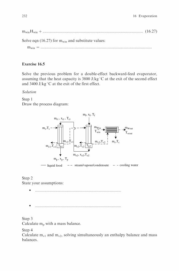
mwinHwin þ ::::::::::::::::::::::::::::::::::::::::::::::::::::::::::::::::::::::::::::::::::::::::::: (16:27)
Solve eqn (16.27) for mwin and substitute values:
mwin ¼ :::::::::::::::::::::::::::::::::::::::::::::::::::::::::::::::::::::::::::::::::::::::::::::::::::::
Exercise 16.5
Solve the previous problem for a double-effect backward-feed evaporator,
assuming that the heat capacity is 3800 J/kg 8C at the exit of the second effect
and 3400 J/kg 8C at the exit of the first effect.
Solution
Step 1Draw the process diagram:
steam/vapour/condensate cooling waterliquid food
mi1 , xi1 , Ti1
ms,Ts
mv1,Tv1 mv2,Tv2
mc2,Tc2mc1,Tc1
mWinTwin
mWout
Twout
mc,Tc
mf, xf, Tf
mo2, xo2,To2
Tb1 Tb2
mp , xp , Tp
Step 2State your assumptions:
l ::::::::::::::::::::::::::::::::::::::::::::::::::::::::::::::::::::::::::::::
l ::::::::::::::::::::::::::::::::::::::::::::::::::::::::::::::::::::::::::::::
Step 3Calculate mp with a mass balance.
Step 4Calculate mv1 and mv2, solving simultaneously an enthalpy balance and massbalances.
232 16 Evaporation

Step 5Calculate the steam consumption with an enthalpy balance.
Step 6Calculate the steam consumption.
Step 7Calculate the cooling water flow rate with an enthalpy balance.
Exercise 16.6
Calculate the required heat transfer area for each effect in Exercise 16.4 if the
overall heat transfer coefficient is 1500 W/m2 8C and 1000 W/m2 8C in the first
and second effects respectively.
Solution
Step 1Write the heat transfer rate equation for the first effect and solve for A1.
Step 2Write the heat transfer rate equation for the second effect and solve for A2.
Exercise 16.7
Solve Exercise 16.4 using the spreadsheet program Evaporator.xls.
SolutionIn the sheet ‘‘2-Effect Forward’’, insert in the yellow cells the data given in Exercise
16.4 and follow the instructions. For the heat transfer area and the overall heat
transfer coefficient of the evaporator and the condenser use your own values.
Indicative values are A1 ¼ A2 ¼ 80m2 in cells H19 and J19; Ac ¼ 50m2
in cell M19; U1 ¼ 1200W�m2 8C in cell H20; U2 ¼ 800W
�m2 8C in cell J20;
Uc ¼ 2500W�m2 8C in cell M20.
Rerun the program using a smaller heat transfer area in the effects, e.g., 70 m2.
Observe how the amount of cooling water, the temperature of cooling water at
the exit of the condenser, and the boiling temperature in each effect are affected.
Explain the results.Rerun the program using 120 8C as steam temperature. Explain the results.Rerun the program using 100 m2 as condenser surface area. Explain the results.
Exercise 16.8
Milk is concentrated in a four-effect forward-feed evaporator from an initial
solids content of 9% to a final solids content of 48%. The feed flow rate is 20000
kg/h, the inlet temperature of the milk in the first effect is 60 8C, the steam
temperature is 75 8C, and the cooling water temperature is 25 8C. The evaporator
Exercises 233

is equipped with a contact condenser with 150 m2 heat transfer area for the
condensation of the vapors exiting the fourth effect. The overall heat transfer
coefficient in the condenser is 2500 W/m2 8C. Find the required heat transfer
area of each effect and the cooling water flow rate, so that the boiling tempera-
ture in the first effect is 70� 1 8C and in the last effect is 40� 1 8C. Calculate thesteam economy. Assume equal heat transfer area in the effects. Assume that the
overall heat transfer coefficient changes as a function of temperature and con-
centration according to: U ¼ 400expð0:03TÞexpð � 2:5xsÞ, where U isW/m2 8C,T is temperature in 8C, and xs is the solids mass fraction.
Solution
ms,Ts
mv1,Tv1
Tb4Tb1 Tb2
steam/vapour/condensate cooling waterliquid food
mo3, xo3,To3mo2, xo2,To2mo1, xo1,To1mp , xp , Tp
mf, xf, Tf mi2, xi2, Ti2 mi3, xi3, Ti3 mi4, xi4, Ti4
mWin
Twin
mWout
Twout
mc,Tcmv4,Tv4
mc4,Tc4mc3,Tc3mc2,Tc2mc1,Tc1 Tb3
mv2,Tv2 mv3,Tv3
Solve the problem using the spreadsheet program Evaporator.xls. In the sheet
‘‘4-Effect Forward’’, insert the data in the yellow cells and follow the instruc-
tions. Insert a trial value for the heat transfer area in cells H18, J18, L18 and
N18 and iterate until a ‘‘FINISH’’ signal is shown in the control panel. Check if
the boiling temperature in cells H23 and N23 is 70� 1�C and 40� 1 8C. If not,use another trial value for the heat transfer area and iterate. Repeat this proce-
dure until the boiling temperature is equal to the given values.
Observe how the overall temperature difference changes as the heat transfer
area changes. Explain this.Observe how the saturation pressure changes from effect to effect. Explain this.Observe how the boiling temperature in the effects changes as the cooling
water flow rate changes. Explain this.Explain why the evaporation rate increases from the first effect to the fourth
effect.Increase the heat transfer area of the condenser to 200 m2 and rerun the
program using the heat transfer area found above for each effect. Observe how
the cooling water flow rate changes. Explain the results.Increase the steam temperature to 80 8C.Rerun the program.Observe how the
boiling temperature and the cooling water flow rate change. Explain the results.
234 16 Evaporation
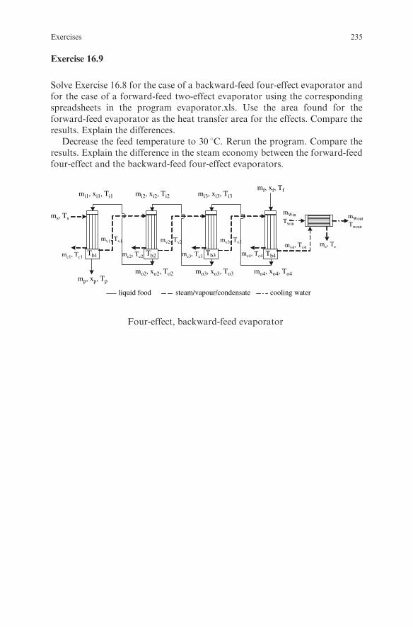
Exercise 16.9
Solve Exercise 16.8 for the case of a backward-feed four-effect evaporator andfor the case of a forward-feed two-effect evaporator using the correspondingspreadsheets in the program evaporator.xls. Use the area found for theforward-feed evaporator as the heat transfer area for the effects. Compare theresults. Explain the differences.
Decrease the feed temperature to 30 8C. Rerun the program. Compare theresults. Explain the difference in the steam economy between the forward-feedfour-effect and the backward-feed four-effect evaporators.
mp, xp, Tp
mc2, Tc2 mc3, Tc3 mc4, Tc4mc1, Tc1
mv1, Tv1 mv2, Tv2 mv3, Tv3 mv4, Tv4mc, Tc
Twin Twout
mWoutmWinms, Ts
mi1, xi1, Ti1 mi2, xi2, Ti2 mi3, xi3, Ti3
mf, xf, Tf
Tb1 Tb2 Tb3 Tb4
mo2, xo2, To2 mo3, xo3, To3 mo4, xo4, To4
steam/vapour/condensate cooling waterliquid food
Four-effect, backward-feed evaporator
Exercises 235

Chapter 17
Psychrometrics
Review Questions
Which of the following statements are true and which are false?
1. The moisture content of air is also called the humidity ratio or absolutehumidity.
2. The humidity ratio of a given air-water vapor mixture increases asthe temperature of the mixture increases.
3. The humidity ratio of an air-water vapor mixture is independent of thepartial pressure of water vapor in the mixture.
4. The relative humidity of an air-water vapor mixture is also called percen-tage saturation or percentage absolute humidity.
5. The relative humidity of an air-water vapor mixture is independent of thetemperature of the mixture.
6. The wet bulb temperature of an air-water vapor mixture is higher thanthe dry bulb temperature.
7. The wet bulb temperature of an air-water vapor mixture is approximatelyequal to the adiabatic saturation temperature.
8. During an adiabatic saturation process, the sensible heat of an air-watervapor mixture decreases but its latent heat increases.
9. The wet bulb temperature of an air-water vapor mixture is equal to the drybulb temperature when the relative humidity is equal to 100%.
10. The dry bulb temperature of an air-water vapor mixture is equal to the dewpoint temperature when the relative humidity is equal to 100%.
11. When a saturated air-water vapor mixture is cooled, some water vapor willcondense.
12. The humid heat of an air-water vapor mixture contains the sensible heatof dry air and the latent heat of the water vapor.
13. The humid volume of an air-water vapor mixture is equal to the inverse ofthe density of the mixture.
14. The properties of an air-water vapor mixture can be determined from apsychrometric chart if two independent property values are known.
15. Every psychrometric chart is drawn for a specific barometric pressure.
S. Yanniotis, Solving Problems in Food Engineering.� Springer 2008
237

16. The wet bulb lines coincide with constant enthalpy lines.17. The psychrometric ratio is a function of the heat and the mass transfer
coefficients.18. The psychrometric ratio of an air-water vapormixture is equal to the humid
heat of that mixture.19. The relative humidity of air can be determined if its dry bulb and wet bulb
temperatures are known.20. When air is cooled below its dew point temperature, both sensible heat and
latent heat are given off.
Examples
Example 17.1
Find the properties of air with 40 8C dry bulb temperature and 28.5 g water/kg
dry air moisture content at 1 atm.
Solution
Step 1
i) Locate the point on the psychrometric chart with 40 8C dry bulb tem-perature and 28.5 g moisture/kg dry air moisture content.
ii) Draw a horizontal line that passes from the point with 28.5 g water/kgdry air moisture content on the y-axis.
iii) Draw a vertical line on the x-axis at the point of 40 8C dry bulb tempera-ture.The point the two lines intersect (point A) represents the point onthe psychrometric chart with 40 8C dry bulb temperature and 28.5 gwater/kg dry air moisture content.
40
Dry bulb temperature (°C)
Hum
idity
(g m
oist
ure/
kg
dry
air)
A30
238 17 Psychrometrics
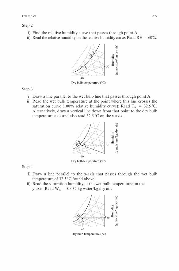
Step 2
i) Find the relative humidity curve that passes through point A.ii) Read the relative humidity on the relative humidity curve: ReadRH=60%.
40
30
60 %
Dry bulb temperature (°C)
Hum
idity
(g m
oist
ure/
kg
dry
air)
A
Step 3
i) Draw a line parallel to the wet bulb line that passes through point A.ii) Read the wet bulb temperature at the point where this line crosses the
saturation curve (100% relative humidity curve): Read Tw = 32.5 8C.Alternatively, draw a vertical line down from that point to the dry bulbtemperature axis and also read 32.5 8C on the x-axis.
40
3032.5 A
Dry bulb temperature (°C)
Hum
idity
(g m
oist
ure/
kg
dry
air)
Step 4
i) Draw a line parallel to the x-axis that passes through the wet bulbtemperature of 32.5 8C found above.
ii) Read the saturation humidity at the wet bulb temperature on they-axis: Read Ww = 0.032 kg water/kg dry air.
40
3032.5
A
Dry bulb temperature (°C)
Hum
idity
(g m
oist
ure/
kg
dry
air)
Examples 239
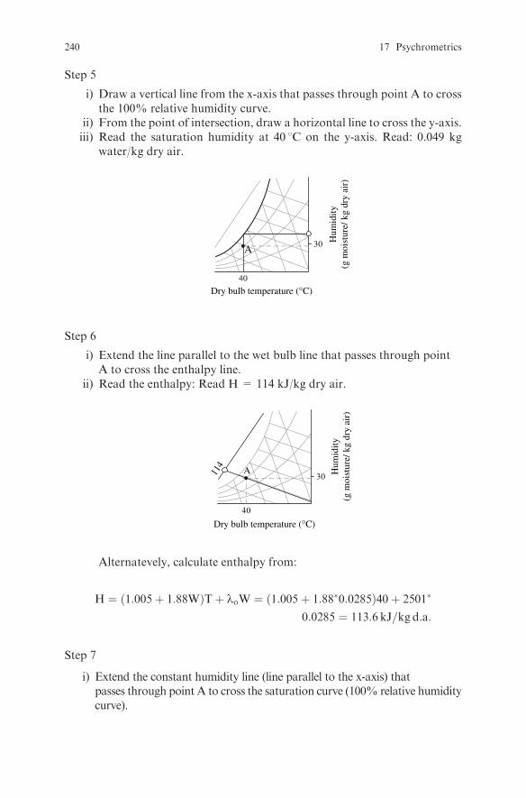
Step 5
i) Draw a vertical line from the x-axis that passes through point A to crossthe 100% relative humidity curve.
ii) From the point of intersection, draw a horizontal line to cross the y-axis.iii) Read the saturation humidity at 40 8C on the y-axis. Read: 0.049 kg
water/kg dry air.
40
30A
Dry bulb temperature (°C)
Hum
idity
(g m
oist
ure/
kg
dry
air)
Step 6
i) Extend the line parallel to the wet bulb line that passes through pointA to cross the enthalpy line.
ii) Read the enthalpy: Read H = 114 kJ/kg dry air.
40
30A11
4
Dry bulb temperature (°C)
Hum
idity
(g m
oist
ure/
kg
dry
air)
Alternatevely, calculate enthalpy from:
H ¼ 1:005þ 1:88Wð ÞTþ loW ¼ 1:005þ 1:88�0:0285ð Þ40þ 2501�
0:0285 ¼ 113:6 kJ=kg d:a:
Step 7
i) Extend the constant humidity line (line parallel to the x-axis) thatpasses through point A to cross the saturation curve (100% relative humiditycurve).
240 17 Psychrometrics

ii) Read the dew-point temperature on the saturation line: Read Tdp¼ 30:58C:
40
3030.5 A
Dry bulb temperature (°C)
Hum
idity
(g m
oist
ure/
kg
dry
air)
Step 8
i) Draw a line parallel to the humid volume line that passes throughpoint A.
ii) Read the humid volume: read vH¼ 0:93m3=kg dry air.
40
30
0.90 0.
95
A
Dry bulb temperature (°C)
Hum
idity
(g m
oist
ure/
kg
dry
air)
iii) Alternatively, calculate the humid volume from:
vH ¼ 0:00283þ 0:00456Wð ÞT ¼ 0:00283þ 0:00456� 0:0285ð Þ273þ 40ð Þ ¼ 0:926m3=kg dry air
Step 9Calculate the percentage saturation or percentage absolute humidity:
PS ¼ 100W
Ws¼ 0:0285
0:049¼ 58:2%
Step 10Calculate the partial pressure of water vapor in the air:Since:
W ¼ 18:02
28:96
p
P� p¼ 0:622
p
P� p
p ¼ WP
0:622þW¼ 0:0285ð Þ 101325ð Þ
0:622þ 0:0285¼ 4439:3 Pa
Examples 241

Step 11Calculate the humid heat:
cs ¼ cA þ cVW ¼ 1:005þ 1:88W ¼ 1:005þ 1:88� 0:0285
¼ 1:059 kJ=kg 8C
Example 17.2
The air of Example 17.1 is heated to 80 8C. Find the relative moisture content,
wet bulb temperature, dew-point temperature, humid volume, and enthalpy of
the air.
Solution
Step 1Since only sensible heat is added to the air, its moisture content and dew-pointtemperature remain constant. Therefore:
i) Draw a horizontal line from point A of Example 17.1.ii) Draw a vertical line on the x-axis at the point of 80 8C dry bulb tempera-
ture. The point at which the two lines intersect (point B) represents thepoint on the psychrometric chart with 80 8C dry bulb temperature and28.5 g water/kg dry air moisture content.
Step 2Find the properties of air at point B following the same procedure as inExample 17.1 for point A.
40
A30B
8040
30
80
AB
Relative humidity = 9.5%
Dry bulb temperature (°C)
Hum
idity
(g m
oist
ure/
kg
dry
air)
Dry bulb temperature (°C)
Hum
idity
(g m
oist
ure/
kg
dry
air)
242 17 Psychrometrics
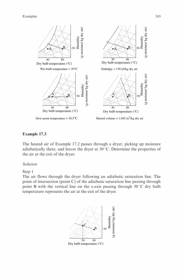
40
30
80
BA
Wet bulb temperature = 39°C
40
30
80
BA
Enthalpy = 158 kJ/kg dry air
40
30
80
BA
Dew-point temperature = 30.5°C
40
30
80
BA
Humid volume = 1.045 m3/kg dry air
Dry bulb temperature (°C)
Dry bulb temperature (°C) Dry bulb temperature (°C)
Dry bulb temperature (°C)
Hum
idity
(g m
oist
ure/
kg
dry
air)
Hum
idity
(g m
oist
ure/
kg
dry
air)
Hum
idity
(g m
oist
ure/
kg
dry
air)
Hum
idity
(g m
oist
ure/
kg
dry
air)
Example 17.3
The heated air of Example 17.2 passes through a dryer, picking up moisture
adiabatically there, and leaves the dryer at 50 8C. Determine the properties of
the air at the exit of the dryer.
Solution
Step 1The air flows through the dryer following an adiabatic saturation line. Thepoint of intersection (point C) of the adiabatic saturation line passing throughpoint B with the vertical line on the x-axis passing through 50 8C dry bulbtemperature represents the air at the exit of the dryer.
50
30
80
BC
Dry bulb temperature (°C)
Hum
idity
(g m
oist
ure/
kg
dry
air)
Examples 243

Step 2Following the same procedure as in the previous examples, find the propertiesof air at point C:Relative humidity = 51%Wet bulb temperature =39 8CEnthalpy = 158 kJ/kg dry airDew-point temperature = 37 8CHumid volume = 0.975 m3/kg dry air
Example 17.4
A stream of 30000 m3/h of air at 30 8C and 70% relative humidity is adiabati-
cally mixed with a stream of 10000 m3/h of air at 40 8C and 50% relative
humidity. Find the resulting dry bulb temperature and the relative humidity
of the mixture.
Solution
Step 1Draw the process diagram:
m1
H1
m3
m2, W2, H2
H3
W1 W3
Step 2State your assumptions: The total pressure of the air is 1 atm.
Step 3
i) Write a total mass balance, a moisture balance, and an enthalpy balancefor the air streams:
m1 þm2 ¼ m3 (17:1)
m1W1 þm2W2 ¼ m3W3 (17:2)
m1H1 þm2H2 ¼ m3H3 (17:3)
244 17 Psychrometrics
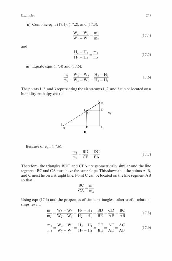
ii) Combine eqns (17.1), (17.2), and (17.3):
W2 �W3
W3 �W1¼ m1
m2(17:4)
and
H2 �H3
H3 �H1¼ m1
m2(17:5)
iii) Equate eqns (17.4) and (17.5):
m1
m2¼W2 �W3
W3 �W1¼ H2 �H3
H3 �H1(17:6)
The points 1, 2, and 3 representing the air streams 1, 2, and 3 can be located on ahumidity-enthalpy chart:
1
3
B
A E
CD
2
F
H
W
Because of eqn (17.6):
m1
m2¼ BD
CF¼ DC
FA(17:7)
Therefore, the triangles BDC and CFA are geometrically similar and the linesegments BC andCAmust have the same slope. This shows that the points A, B,and C must lie on a straight line. Point C can be located on the line segment ABso that:
BC
CA¼ m1
m2
Using eqn (17.6) and the properties of similar triangles, other useful relation-ships result:
m1
m3¼W2 �W3
W2 �W1¼ H2 �H3
H2 �H1¼ BD
BE¼ CD
AE¼ BC
AB(17:8)
m2
m3¼W3 �W1
W2 �W1¼ H3 �H1
H2 �H1¼ CF
BE¼ AF
AE¼ AC
AB(17:9)
Examples 245

Step 4To solve the problem:
i) Locate points A and B on the psychrometric chart.ii) Read the humid volume of each stream: vH1 = 0.88 m3/kg d.a. and vH2
= 0.92 m3/kg d.a.iii) Calculate the mass flow rate:
m1 ¼Q1
vH1¼ 30000 m3=h
0:88 m3=kg d:a:¼ 34091 kg d:a:=h
m2 ¼Q2
vH2¼ 10000 m3=h
0:92 m3=kg d:a:¼ 10870 kg d:a:=h
and
m1
m2¼ 34091 kg d:a:=h
10870 kg d:a:=h¼ 3:1
iv) Draw the line connecting points A and B.v) Locate point C by dividing with a ruler the line segment AB into two
parts such that:
BC
CA¼ m1
m2¼ 3:1
66%
A
BC
32Dry bulb temperature (°C)
Hum
idity
(g m
oist
ure/
kg
dry
air)
vi) Read the properties of air at point C as:Dry bulb temperature = 32 8C,Relative humidity = 66%.
Alternative solution
Step 1Divide eqn (17.3) by m3:
m1
m3H1 þ
m2
m3H2 ¼ H3 (17:10)
246 17 Psychrometrics
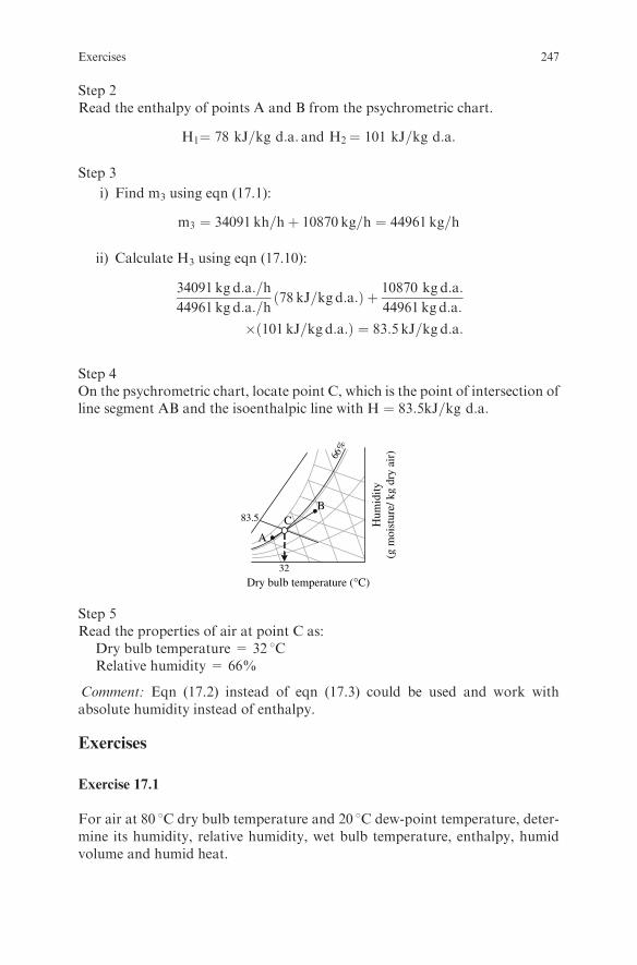
Step 2Read the enthalpy of points A and B from the psychrometric chart.
H1¼ 78 kJ=kg d:a: and H2¼ 101 kJ=kg d:a:
Step 3
i) Find m3 using eqn (17.1):
m3 ¼ 34091 kh=hþ 10870 kg=h ¼ 44961 kg=h
ii) Calculate H3 using eqn (17.10):
34091 kg d:a:=h
44961 kg d:a:=h78 kJ=kg d:a:ð Þ þ 10870 kg d:a:
44961 kg d:a:
� 101 kJ=kg d:a:ð Þ ¼ 83:5 kJ=kg d:a:
Step 4On the psychrometric chart, locate point C, which is the point of intersection ofline segment AB and the isoenthalpic line with H ¼ 83:5kJ=kg d:a:
A
32
BC
66%
83.5
Dry bulb temperature (°C)
Hum
idity
(g m
oist
ure/
kg
dry
air)
Step 5Read the properties of air at point C as:
Dry bulb temperature = 32 8CRelative humidity = 66%
Comment: Eqn (17.2) instead of eqn (17.3) could be used and work withabsolute humidity instead of enthalpy.
Exercises
Exercise 17.1
For air at 80 8C dry bulb temperature and 20 8C dew-point temperature, deter-mine its humidity, relative humidity, wet bulb temperature, enthalpy, humidvolume and humid heat.
Exercises 247
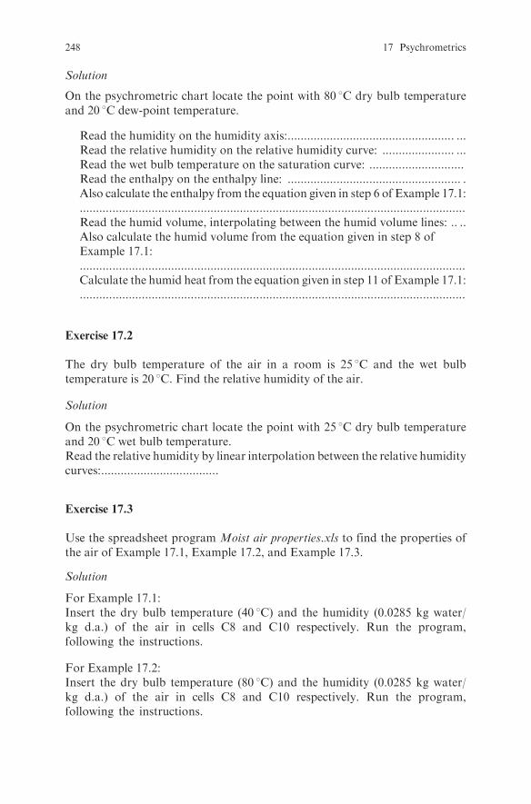
Solution
On the psychrometric chart locate the point with 80 8C dry bulb temperatureand 20 8C dew-point temperature.
Read the humidity on the humidity axis:................................................... ...Read the relative humidity on the relative humidity curve: ...................... ...Read the wet bulb temperature on the saturation curve: .............................Read the enthalpy on the enthalpy line: ..................................................... .Also calculate the enthalpy from the equation given in step 6 of Example 17.1:......................................................................................................................Read the humid volume, interpolating between the humid volume lines: .. ..Also calculate the humid volume from the equation given in step 8 ofExample 17.1:......................................................................................................................Calculate the humid heat from the equation given in step 11 of Example 17.1:......................................................................................................................
Exercise 17.2
The dry bulb temperature of the air in a room is 25 8C and the wet bulbtemperature is 20 8C. Find the relative humidity of the air.
Solution
On the psychrometric chart locate the point with 25 8C dry bulb temperatureand 20 8C wet bulb temperature.Read the relative humidity by linear interpolation between the relative humiditycurves:....................................
Exercise 17.3
Use the spreadsheet program Moist air properties.xls to find the properties ofthe air of Example 17.1, Example 17.2, and Example 17.3.
Solution
For Example 17.1:Insert the dry bulb temperature (40 8C) and the humidity (0.0285 kg water/kg d.a.) of the air in cells C8 and C10 respectively. Run the program,following the instructions.
For Example 17.2:Insert the dry bulb temperature (80 8C) and the humidity (0.0285 kg water/kg d.a.) of the air in cells C8 and C10 respectively. Run the program,following the instructions.
248 17 Psychrometrics
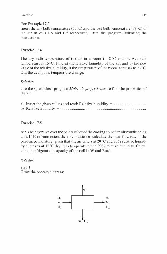
For Example 17.3:Insert the dry bulb temperature (50 8C) and the wet bulb temperature (39 8C) ofthe air in cells C8 and C9 respectively. Run the program, following the
instructions.
Exercise 17.4
The dry bulb temperature of the air in a room is 18 8C and the wet bulb
temperature is 15 8C. Find a) the relative humidity of the air, and b) the new
value of the relative humidity, if the temperature of the room increases to 23 8C.Did the dew-point temperature change?
Solution
Use the spreadsheet program Moist air properties.xls to find the properties of
the air.
a) Insert the given values and read: Relative humidity =................................b) Relative humidity = ...................................................................................
Exercise 17.5
Air is being drawn over the cold surface of the cooling coil of an air conditioning
unit. If 10 m3/min enters the air conditioner, calculate the mass flow rate of the
condensed moisture, given that the air enters at 20 8C and 70% relative humid-
ity and exits at 12 8C dry bulb temperature and 90% relative humidity. Calcu-
late the refrigeration capacity of the coil in W and Btu/h.
Solution
Step 1Draw the process diagram:
ma
Hi
Wi
ma
Ho
Wo
q
mw, Hw
Exercises 249

Step 2State your assumptions:
l The system operates at steady state.l The condensed water exits at the exit air temperature.
Step 3Use the psychrometric chart or the spreadsheet programMoist air properties.xlsto find the humidity, the enthalpy and the humid volume of the air at the inlet aswell as the humidity and the enthalpy of the air at the outlet.
Step 4Write a mass balance on the moisture:
maWi ¼ ::::::::::::::::::::::::::::::::::::::: þ ::::::::::::::::::::::::::::::::::::::::::::::::::::
Step 5Calculate ma:
..........................................................................................................................
Step 6Calculate mw:
..........................................................................................................................
Step 7Write an enthalpy balance over the cooler:
maHi ¼ :::::::::::::::::::::::::::::::::::::þ :::::::::::::::::::::::::þ :::::::::::::::::::::::::::::::
Step 8Substitute values and solve for q:
q ¼ ::::::::::::::::::::::::::::::::::::::::::::::::::::::::::::::::::::::::::::::::::::::::::::::::::::::::
Exercise 17.6
Air at 20 8C and 60% relative humidity is heated to 90 8C and then enters a
continuous dryer in an adiabatic operation. The air exits at 40 8C. Calculate: a)the inlet volumetric flow rate of air required to remove 20 kg of water/h from
the product and b) the required energy to heat the air.
250 17 Psychrometrics

Solution
Step 1Draw the process diagram:
ma
H1
W1ma
H2
W1
Heater
vH1
Dryer1 2 3 ma
H2
W3
Step 2Find the properties of the air at the inlet using a psychrometric chart or thespreadsheet program Moist air properties.xls.Air at 20 8C dry bulb temperature and 60% relative humidity:
Humidity W1 = ....................................................................................Enthalpy H1 = .....................................................................................Humid volume vH1 = ...........................................................................
Air at 90 8C dry bulb temperature and humidity W1:
Enthalpy H2 = ..........................................................................Air at 40 8C dry bulb temperature and enthalpy H2:
Humidity W3 = .........................................................................
Step 3Write a mass balance on the moisture between points 2 and 3:
maðW3 �W1Þ ¼ :::::::::::::::::::::::::::::::::::::::::::::::::::
Substitute values and calculate ma:
ma ¼ :::::::::::::::::::::::::::::::::::::::::::::::::::::::::::::::::::::::::
Use the humid volume to calculate the volumetric flow rate:..........................................................................................................................
Step 4Write an enthalpy balance on the air between points 1 and 2 and calculate therequired energy:..........................................................................................................................
Exercises 251
Chapter 18
Drying
Review Questions
Which of the following statements are true and which are false?
1. If the drying rate is high, case hardening may result.2. Case hardening is reduced if high humidity air is used in the dryer.3. The free moisture content in a product is independent of the drying air
temperature.4. Only a fraction of the free moisture content can be removed with drying.5. Unbound moisture content exerts a vapor pressure equal to the vapor
pressure of pure water at the same temperature.6. Unbound moisture may move to the surface through capillaries.7. If moisture moves to the surface through capillaries, the drying time is
proportional to the square of the thickness of the solid.8. The critical moisture content in a product is independent of the initial
drying rate.9. At a moisture content less than the critical moisture content, the surface of
the product still remains fully wet.10. The equilibrium moisture content of a product in a dryer is independent of
the air temperature in the dryer.11. The equilibriummoisture content of a product in a dryer can be predicted if
the desorption isotherm of the product at the same temperture is known.12. The equilibrium moisture content of a product in a dryer can be predicted
if the adsorption isotherm of the product at the same temperature isknown.
13. The GABmodel successfully fits experimental data of equilibriummoisturecontent for water activity values up to 0.9.
14. As the moisture in a product approaches the equilibrium moisture content,the rate of drying tends toward zero.
15. The drying rate in a constant rate period is controlled by the internalresistance to heat and mass transfer.
16. The rate of heat transfer inside a product during drying is limited by theheat transfer coefficient at the surface.
S. Yanniotis, Solving Problems in Food Engineering.� Springer 2008
253

17. Air velocity significantly affects the drying rate at the constant rate period.18. The driving force formass transfer in the dried layer inside a product during
the falling rate period is the water vapor pressure gradient.19. The heat and mass transfer coefficients in a fluidized bed dryer are higher
than in a tunnel dryer.20. Because the air temperature in spray drying is high, the product quality is
inferior.21. The residence time of the product in a spray drier is in the range of a few
seconds.22. The droplet size in a spray dryer depends only on the type of atomizer used
and is independent of the physical properties of the product.23. Shrinkage of a freeze dried product may be significant.24. Rehydration of freeze dried products is difficult.25. The rate of drying in freeze drying is mainly controlled by the external
resistance to heat and mass transfer.26. The rate of drying in spray drying is mainly controlled by the external
resistance.27. The product surface temperature during the constant rate period is always
equal to the wet bulb temperature of drying air.28. The drying cost in a spray dryer is lower than in a freeze dryer.29. Products dried by explosion puff drying have good rehydration properties.30. The drying time in the falling rate period will be proportional to the square
of the thickness of the product, even if the diffusion coefficient varies withthe moisture content.
31. Cocurrent flow in a continuous dryer gives faster drying than counter-current flow.
32. Cocurrent flow results in less heat damage to the product than counter-current flow for heat sensitive products.
33. Drying time is proportional to the thickness of a product if external masstransfer controls.
34. Recirculation of a fraction of the air in a dryer increases thermal efficiency.35. Recirculation of a fraction of the air in a dryer decreases drying time.36. Superheated steam is not a suitable drying medium for drying foodstuffs.37. The use of superheated steam as a drying medium increases energy
consumption.38. Vegetables may be dried in belt dryers.39. Pretreatment of fruits and vegetables with sulphur dioxide prevents none-
nzymatic browning during drying.40. Products such as milk, coffee, and eggs are dried in spray dryers.41. Pneumatic dryers are used for drying powders.42. Explosion puff dryers may be used as secondary dryers in the finish drying
of pieces of fruits and vegetables.43. Instant potato powder may be produced in a drum dryer.44. Freeze drying may be used to dry premium coffee.45. Peas may be dried in a fluidized bed dryer.
254 18 Drying

46. Fluidized bed dryers are suitable for drying food particles up to 30 mm insize.
47. Milk dried in drum dryers is useful in the prepared-food industry because ithas high water-binding capacity but it has cooked flavor.
48. Air temperatures of 120–250 8C at the inlet and 70–95 8C at the outlet areused in spray dryers.
49. Roughly 2 to 3 kg of steam are needed in a spray dryer to evaporate 1 kg ofmoisture from a product.
50. Spray drying is used to dry egg products after treatment with bakers yeastor glucose oxidase-catalase enzyme to remove glucose before drying.
Examples
Example 18.1
A drying test was carried out in a laboratory dryer to determine the drying ratecurve and the critical moisture content of a vegetable. The sample was cut intosmall cubes and placed in a tray with 0:4cm� 0:4cm surface area. The tray wasplaced in a dryer for 17 hours and dried at constant drying conditions with anair stream that was flowing parallel to the surface of the tray. From time to time,the tray was weighed, while in a separate experiment the initial moisture contentof the sample was determined. If the initial moisture content of the sample was89% (wet basis) and the weight of the product in the tray varied with time asgiven below, a) plot the drying curve and the drying rate curve, and b) estimatethe rate of drying at the constant-rate period, the critical moisture content, theequilibrium moisture content, and the free moisture content under the givendrying conditions.
Time Net weight, mp
(min) (kg)
0 5.000
30 3.860
60 2.700
90 2.250
120 1.900
180 1.332
240 1.164
300 1.020
360 0.912
480 0.816
540 0.780
600 0.720
660 0.696
720 0.684
780 0.655
Examples 255
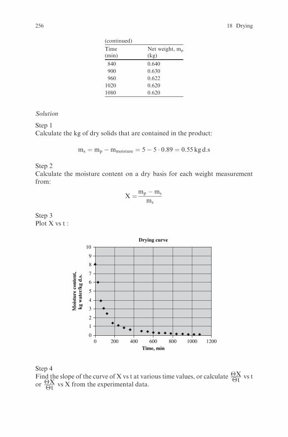
(continued)
Time Net weight, mp
(min) (kg)
840 0.640
900 0.630
960 0.622
1020 0.620
1080 0.620
Solution
Step 1Calculate the kg of dry solids that are contained in the product:
ms ¼ mp �mmoisture ¼ 5� 5 � 0:89 ¼ 0:55 kg d:s
Step 2Calculate the moisture content on a dry basis for each weight measurementfrom:
X ¼mp �ms
ms
Step 3Plot X vs t :
Drying curve
0
1
2
3
4
5
6
7
8
9
10
0 200 400 600 800 1000 1200Time, min
Moi
stur
e co
nten
t,kg
wat
er/k
g d.
s.
Step 4Find the slope of the curve of X vs t at various time values, or calculate �X
�tvs t
or �X�t
vs X from the experimental data.
256 18 Drying

Step 5Plot �X
�t vs X and read from the plot the critical moisture content Xc, thedrying rate Rc at the constant-rate period, and the equilibriummoisture contentXe on the x-axis (moisture content at drying rate = 0) or from the given data.
Read:
Rc ¼ 0:24 kgwater�minm2
Xc ¼ 4:95 kgwater=kg d:s:
Xe ¼ 0:127 kg water=kg d:s:
Step 6Calculate the free moisture content at the beginning of drying (moisture thatcan be removed from the solid under the given drying air conditions of tem-perature and humidity):
Xfree ¼ Xo �Xe ¼ 8:09� 0:127 ¼ 7:964 kgwater=kg d:s:
It is suggested that steps 1 to 5 be carried out on a spreadsheet. See the
spreadsheet Drying 1.xls.
Drying rate curve
0.00
Xe
Xc
Rc
0.05
0.10
0.15
0.20
0.25
0.30
0 2 4 6 8Moisture content, kg water/kg d.s.
Dry
ing
rate
,kg
wat
er/m
in m
2
Comments:
1) The linear part of the falling rate period is missing in this product,2) The equilibrium moisture content Xe could also be determined from the
desorption isotherm of the product (if available) at the same temperatureas the temperature of the air in the dryer.
Examples 257
Example 18.2
Calculate the time necessary to dry a product from 90% to 25% moisture (wet
basis) in an industrial dryer where 2 kg dry solid/m2 surface area exposed to the
air is loaded. It is given that the critical moisture content is 5 kg water/ kg dry
solid, the equilibrium moisture content is 0.033 kg water/ kg dry solid, and the
drying rate at the critical moisture content is 3 kg water/m2h under the specified
drying conditions.
Solution
Step 1Express the moisture content on a dry basis:
i) Initial moisture content:
Xo ¼Yo
1�Yo¼ 0:9
1� 0:9¼ 9 kgwater=kg d:s:
ii) Final moisture content:
Xf ¼Yf
1�Yf¼ 0:25
1� 0:25¼ 0:333 kgwater=kg d:s:
Step 2Calculate the time for the constant-rate period:
tc ¼ms
A
Xo �Xc
Rc¼ 2 kg d:s:=m2� � 9� 5ð Þkgwater=kg d:s:
3 kgwater=m2h¼ 2:67 h
Step 3Calculate the time for the falling-rate period:
Assumption: Due to a lack of more detailed data, assume that the drying rate in
the falling-rate period is directly proportional to the free moisture content.
With this assumption the time for the falling-rate period can be calculated
from:
tf ¼ms
A
X1 �Xe
RclnXc �Xe
Xf �Xe¼
¼ 2kg d:s:=m2� � 5� 0:0333ð Þ kgwater=kg d:s:
3 kgwater=m2hln
5� 0:033
0:333� 0:033¼ 9:29 h
258 18 Drying

Step 4Calculate the total time:
t ¼ tc þ tf ¼ 2:67hþ 9:29h ¼ 11:96 h
Example 18.3
Calculate the drying time for a product with ms=A ¼ 3kgd:s:=m2 and thefollowing values for the rate of drying at various moisture contents:
X Rkg water/kgd.s.
kg water/(kg d.sh m2)
4.0 20.0
3.8 17.0
3.5 14.0
2.5 8.0
2.0 6.0
1.2 3.0
1.0 1.9
0.9 1.6
0.8 1.3
0.7 1.2
0.6 1.0
Solution
Step 1Plot the given data:
0
4
8
12
16
20
0 1 2 3 4 5
X, kg water/kg d.s.
R,
kg w
ater
/h m
2
Examples 259
Step 2As shown in the plot, the relation betweenR andX is not linear. The drying timecan be calculated without the assumption of a linear relation using numericalintegration.
By definition R is:
R ¼ �ms
A
dX
dt(18:1)
Integration of eqn (18.1) gives:
t ¼ �ms
A
Z X2
X1
1
RdX
ms
A
Z X1
X2
1
RdX (18:2)
Since an analytical relationship between 1/R and X is not available, the integral
can be approximated using numerical integration. Thus:
Z X1
X2
1
RdX �
X DXRaverage
Numerical integration ofRX1
X2
1
RdX gives (see the spreadsheet program Drying
2.xls):
Z X1
X2
1
RdX �
X DXR average
¼ 0:782 hm2=kg d:s:
Substitute values in eqn (18.2) and calculate the time:
t ¼ms
A
Z X1
X2
1
RdX ¼ 3 kg d:s:=m2
� �0:782 hm2=kg d:s:� �
¼ 2:35 h
Example 18.4
Tomato paste placed in trays is dried in a pilot dryer. The air in the dryer
flowing parallel to the surface of the tray has a temperature of 100 8C and
2.5% relative humidity. Heat is transferred to the product by convection and
radiation at the exposed surface as well as by conduction from the bottom of
the tray. The convection heat transfer coefficient hc is 30W/m2 8C, the
radiant heat transfer coefficient hR is 9W/m2 8C, and the overall heat transfer
coefficient U at the bottom (including the resistances of convection at the
bottom, conduction in the metal wall of the tray, and conduction through the
solid food) is 10 W/m2 8C. The temperature of the radiating surface above the
tray is 110 8C. Calculate the drying rate at the constant-rate period.
260 18 Drying

Solution
Step 1Draw the process diagram:
Ts
Ws,Wa,
Ta
TR
Radiating surface
U
hc
Step 2Since radiation and conduction are included in this process, the surface tem-perature of the product Ts will be higher than the wet bulb temperature of theair even in the constant-rate period. The drying rate at the constant-rate periodfor this case can be calculated from (Ref. 3,7):
Rc ¼q
Als¼ hc þUð Þ Ta � Tsð Þ þ hR TR � Tsð Þ
ls¼ kyMa Ws �Wað Þ (18:3)
Eqn (18.1) can be rearranged to give:
Ws �Wað Þlscs
¼ 1þ U
hc
� �Ta � Tsð Þ þ hR
hcTR � Tsð Þ (18:4)
Step 3Find Ws and Ts:
i) Find the humidity and the humid heat of the air from the psychrometricchart or from the spreadsheet program Moist air properties.xls:
Wa ¼ 0:016 kgwater=kg dry air
cs ¼ 1:035 kJ=kg�C
ii) Substitute values in eqn (18.4):
Ws � 0:016ð Þls1:035
¼ 1þ 10
30
� �100� Tsð Þ þ 9
30110� Tsð Þ (18:5)
Ws and Ts represent a point on the saturation humidity curve on thepsychrometric chart. Thus, eqn (18.5) has to be solved by trial and error
Examples 261
so that Ws and Ts will satisfy eqn (18.5) and the saturation humiditycurve on the psychrometric chart. Such a trial and error solution is givenin the spreadsheet program Drying 3.xls.
iii) Run the spreadsheet program Drying 3.xls to find Ws and Ts.Insertthe properties of the air, insert the values of the heat transfer coeffi-cients hc, hR, and U, and the value of the radiating surface tempera-ture TR. Run the program, following the instructions. Read theresults.
Read Ts ¼ 42:8�C
Ws ¼ 0:058 kgwater=kg dry air
Step 4Substitute values in eqn (18.3) and find Rc:
Rc ¼ 30þ 10ð Þ 100� 42:8ð Þ þ 9 110� 42:8ð Þ2400000
¼ 1:2� 10�3kg=m2s
¼ 4:34kg=m2h
Rc is also given directly in the program Drying 3.xls.
Example 18.5
Slices of beets are dried in a dryer as part of a process to produce dehydrated
powder for use as a coloring agent in a dressing. The air enters the dryer at a
flow rate of 12000 m3/h, 50 8C temperature, and 10% relative humidity, and
exits at 34 8C temperature. If the initial moisture content of the beet is 90%
and the beet feed rate is 100 kg/h, calculate the final moisture content of the
product.
Solution
Step 1Draw the process diagram:
ma, Wi ma, Wo
ms, Xo
mFi, Yi mFo, Yo
ms, Xi
Step 2State your assumptions:The air in the dryer follows an adiabatic humidification path.
262 18 Drying

Step 3Using the psychrometric chart or the spreadsheet programMoist air properties.xls,find the air properties at the inlet and the outlet of the dryer.
Inlet: Humidity Wi ¼ 0:0077 kgwater=kg d:a:Humid volume vH ¼ 0:925m3
�kg d:a:
Wet bulb temperature Tw ¼ 23:9�C
Since the air follows an adiabatic humidification path during its flow throughthe dryer, the wet bulb temperature at the outlet will be equal to that at the inlet.Thus, using the dry bulb temperature at the exit and the wet bulb temperature asinput variables in the psychrometric chart or the spreadsheet programMoist airproperties.xls, find the humidity at the outlet.
Humidity W� ¼ 0:0145 kgwater=kg d:a:
Step 4Calculate the mass flow rate of air:
ma ¼Q
vH¼ 12000m3=h
0:925m3=kg d:a:¼ 12973 kg d:a:=h
Step 5Express the product feed rate and the moisture at the inlet on a dry basis:
ma ¼ mFi 1�Yið Þ ¼ 100kg product
h
� �1� 0:90ð Þkg dry solids
kg product¼ 10
kg dry solids
h
Xi ¼mFi �ms
ms¼ 100� 10ð Þkgwater=h
10 kg dry solids=h¼ 9
kgwater
kg dry solids
Step 6Write a moisture balance over the dryer to calculate Xo:
msXi þmaWi ¼ msXo þmaWo
Solve for Xo:
Xo ¼msXi �ma Wo �Wið Þ
ms¼
¼ 10 kg d:s:=hð Þ 9 kgwater=kg d:s:ð Þ � 12973 kg d:a:=hð Þ 0:0145� 0:0077ð Þkgwater=kg d:a:10 kg dry solids=h
¼
¼ 0:178 kgwater=kg dry solids
The moisture of the product at the outlet on a wet basis is:
Yo ¼Xo
1þXo¼ 0:178
1þ 0:178
kgwater=kg d:s:
kg products=kg d:s:¼ 0:151kgwater=kg product
or 15.1 % moisture content
Examples 263
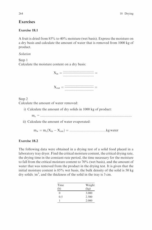
Exercises
Exercise 18.1
A fruit is dried from 85% to 40%moisture (wet basis). Express the moisture on
a dry basis and calculate the amount of water that is removed from 1000 kg of
product.
Solution
Step 1Calculate the moisture content on a dry basis:
Xin ¼:::::::::::::::::::::::::::::::::
:::::::::::::::::::::::::::::::::¼
Xout ¼:::::::::::::::::::::::::::::::
:::::::::::::::::::::::::::::::¼
Step 2Calculate the amount of water removed:
i) Calculate the amount of dry solids in 1000 kg of product:
ms =..................................................................................................
ii) Calculate the amount of water evaporated:
mw ¼ ms Xin �Xoutð Þ ¼ :::::::::::::::::::::::::::::::::::::::kgwater
Exercise 18.2
The following data were obtained in a drying test of a solid food placed in a
laboratory tray dryer. Find the critical moisture content, the critical drying rate,
the drying time in the constant-rate period, the time necessary for the moisture
to fall from the critical moisture content to 70% (wet basis), and the amount of
water that was removed from the product in the drying test. It is given that the
initial moisture content is 85% wet basis, the bulk density of the solid is 50 kg
dry solids /m3, and the thickness of the solid in the tray is 3 cm.
Time Weight(h) (kg)
0 3.000
0.5 2.500
1 2.000
264 18 Drying

(continued)
Time Weight(h) (kg)
2 1.600
3 1.500
4 1.435
6 1.420
8 1.410
10 1.405
12 1.400
13 1.400
Solution
Step 1Express the moisture content of the given data on a dry basis for each givenpoint.
Step 2Calculate the amount of dry solid per unit surface area:
ms
A¼ thickness in the tray� ::::::::::::::::¼::::::::::::::: � ::::::::::::::::::
¼:::::::::::::::kg d:s:=m2
Step 3Calculate the drying rate R for each given point from:
R ¼ �ms
A
dX
dt
Step 4Plot R vs X.
Step 5Read the values of Xc and Rc from the plot.
Step 6Calculate the drying time in the constant-rate period:
t ¼:::::::::::::::::::::::::::::
¼ ::::::::::::::::::::::::::::::::
Step 7Read the drying rate at a moisture content of 80% and 70% from the plot, andcalculate the required drying time using the assumption that the falling rateperiod is a linear function of X.
t ¼:::::::::::::::::::::::::::::
¼ ::::::::::::::::::::::::::::::::
Exercises 265

Step 8Calculate the amount of water removed in the drying test:
mw ¼ ::::::::::::::::::::::::::::::::::::::
Exercise 18.3
Using the spreadsheet program Drying 3.xls, study the effect of radiation andconduction on the product surface temperature and the drying rate at theconstant-rate period for Example 18.4, leaving hc constant.
Solution
For the following cases, read the drying rate Rc and the surface temperature Ts.Compare Ts to the wet bulb temperature Tw. Comment on the results.
1) hr ¼ 0;TR ¼ 110 and U ¼ 02) hr ¼ 9;TR ¼ 110 and U ¼ 03) hr ¼ 10;TR ¼ 150 and U ¼ 04) hr ¼ 0;TR ¼ 110 and U ¼ 105) hr ¼ 0;TR ¼ 110 and U ¼ 20
Exercise 18.4
Diced potatoes initially dried in a belt dryer to 20% moisture will be furtherdried in a bin dryer to 5%moisture. Calculate the required time to dry a potatocube from 20% to 5% if the effective diffusion coefficient of moisture inpotatoes is 2:6� 10�11m2
�s, the equilibrium moisture content at the tempera-
ture and humidity of the air used is 0:03kgwater=kgd:s:, and the size of thepotato cube is 10 mm� 10 mm� 10 mm.
Solution
Step 1State your assumptions:
l Moisture movement in the potato cube is diffusion controlled.l Moisture is initially uniform throughout the cube.l The external resistance to mass transfer is negligible.l The diffusion coefficient is constant.l Shrinkage is neglected.
Step 2Express the moisture content in kg water/kg dry solid:
Initial moisture content X� ¼ :::::::::::::::::::::::::::::::::::::::::::::::::::::::::::::
266 18 Drying

Average final moisture content Xm ¼ :::::::::::::::::::::::::::::::::::::::::::::::::Equilibrium moisture content Xe ¼ ::::::::::::::::::::::::::::::::::::::::::::::::::::
Step 3Apply the solution of the unsteady state mass transfer equation (Fick’s 2nd law)to the average concentration in the x, y, and z directions for negligible surfaceresistance (see Table 10.1 and Table 13.1):
Xe �Xm
Xe �Xo¼ 8
p2X1n¼0
1
2nþ 1ð Þ2exp � 2nþ 1ð Þ2p2
4Fo
!¼
¼ 8
p2exp �2:47Foð Þ þ 1
9exp �22:2Foð Þ þ 1
25exp �61:7Foð Þ þ :::
� �
Use the spreadsheet program Mass transfer-Negligible Surface Resistance.xls.Insert the parameter values Lx;Ly;Lz;Co;Ce and Dij.Run the program until the Cmean ¼ Xm. Read the time.
Exercise 18.5
In a vegetable dryer, room air at 25 8C and 60% relative humidity is mixed witha portion of the exit air from the dryer. The mixture is heated to 90 8C and
attains 10% relative humidity before entering the dryer. The air leaves the dryerat 60 8C. Find the relative humidity of the air at the exit of the dryer, therequired fresh air flow rate, the recirculation rate, and the steam consumptionin the air heater, if the initial moisture content of the vegetable is 80%, the finalmoisture content is 20% (wet basis), the feed rate to the dryer is 500 kg/h, and
the air is indirectly heated by 120 8C saturated steam. If, for the same productconditions, air recirculation was not used, but instead the same total mass airflow rate was heated to 90 8C before entering the dryer, calculate the steamconsumption and the relative humidity of the air at the exit.
Solution
Step 1Draw the process diagram:
500 kg/h
60%RH60°C
80% 20%
maR
mFo
ma
mst
21 3DRYERMa
120°C
90°C, 10%RH25°C
ma
Exercises 267

Step 2State your assumptions: The operation of the dryer is adiabatic.
Step 3Calculate the amount of water evaporated in the dryer:
i) Calculate the dry solids content in the feed:
ms ¼ :::::::::::::::::::::::::::::::::::::::::::::::
ii) Calculate the moisture content of the product at the inlet and the outleton a dry basis:
Xi ¼:::::::::::::::::::::::::
¼ :::::::::::::::::::::::::kgwater=kgd:s:
Xo ¼:::::::::::::::::::::::::
¼ :::::::::::::::::::::::::kgwater=kgd:s:
iii) Calculate the amount of water evaporated:
mw ¼ :::::::::::::kg d:s:
h:::::::::: � :::::::::::ð Þ kgwater
kg d:s:¼ ::::::::::::: kgwater
h
Step 4Find the humidity and the enthalpy at points 1, 2, and 3 from the psychrometricchart or from the spreadsheet program Moist air properties.xls, as well as therelative humidity at point 3:
W1 ¼ :::::::::::::::::::::::::::::::::::::::::::::::::
W2 ¼ :::::::::::::::::::::::::::::::::::::::::::::::::
W3 ¼ :::::::::::::::::::::::::::::::::::::::::::::::::
H1 ¼ :::::::::::::::::::::::::::::::::::::::::::::::::
H2 ¼ :::::::::::::::::::::::::::::::::::::::::::::::::
H3 ¼ :::::::::::::::::::::::::::::::::::::::::::::::::
RH3 ¼ :::::::::::::::::::::::::::::::::::::::::::::::
Step 5Calculate the recirculation rate using the appropriate relationship for the mix-ing of two air streams developed in Example 17.4:
maR
m2¼ :::::::::::::::::::::::::::::::::::::::::
268 18 Drying

Step 6Calculate the mass flow rate of air in the dryer by dividing the total amount ofwater evaporated, by the moisture picked up by the air:
m2 ¼ :::::::::::::::::::::::::::::::::::::::::::::::::kg dry air=h
Step 7Calculate the mass flow rate of fresh air to the heater from an air mass balance
on the heater and the known ratio ofmaRm2
:
ma ¼ :::::::::::::::::::::::::::::::::::::::::::::::::::::::::::::::::::
Step 8Find the humid volume of fresh air and calculate its volumetric flow rate:
Qa ¼ ::::::::::::::::::::::::::::::::::::::::::::::::::::::::::m3=h
Step 9Write an enthalpy balance in the air heater to calculate the steam consumption(assume that the condensate exits at the saturation temperature):
mst ¼ ::::::::::::::::::::::::::::::::::::::::::::::::::::::::::kg=h
Step 10Draw the process diagram for the case in which recirculation is not used:
500 kg/h
80%
21 3DRYER
20%
mFo
Ma
mst 120°C
90°C60%RH25°C
Ma
Step 11Find the enthalpy of the air at point 2 from the psychrometric chart or from thespreadsheet program Moist air properties.xls, and write an enthalpy balance inthe air heater to calculate the steam consumption.
Exercises 269

Step 12Write a moisture balance on the dryer and calculate the moisture content of theair at point 3.
Step 13Find the relative humidity at point 3 from the psychrometric chart or from thespreadsheet program Moist air properties.xls.
Step 14Compare the results.
Exercise 18.6
A countercurrent tunnel dryer is used to dry 500 kg/h of a vegetable from 85%
to 15% moisture. Room air at 20 8C and 50% relative humidity is heated to
90 8C in an air heater before entering the dryer, flows through the dryer, and
exits at 90% relative humidity. Calculate the required air flow rate and the
required energy in the air heater.
Solution
Step 1Draw the process diagram.
Step 2State your assumptions: :::::::::::::::::::::::::::::::::::::::::::::::::::::::::::::::
Step 3Calculate the amount of water removed from the product.
a) Calculate the solids content:
Xs ¼ :::::::::::::::::::::::::::::::::::::::::::::::::::
b) Calculate moisture content of the product on a dry basis at the inlet andthe outlet of the dryer:
Xi ¼ :::::::::::::::::::::::::::::::::::::::::::::::::::
X0 ¼ :::::::::::::::::::::::::::::::::::::::::::::::::::
c) Calculate the amount of water removed from the product:
mw ¼ :::::::::::::::::::::::::::::::::::::::::::::::::::kg=h
Step 4Find the air properties at the inlet:
270 18 Drying
W1 ¼ ::::::::::::::::::::::::::::::::::::::::::::::::
vH1 ¼ ::::::::::::::::::::::::::::::::::::::::::::::::
H1 ¼ ::::::::::::::::::::::::::::::::::::::::::::::::
Step 5Find the air properties after the heater:
Tw2 ¼ ::::::::::::::::::::::::::::::::::::::::::::
H2 ¼ :::::::::::::::::::::::::::::::::::::::::::::
Step 6Find the air properties at the exit of the dryer:
W3 ¼ ::::::::::::::::::::::::::::::::::::::
Tw3 ¼ ::::::::::::::::::::::::::::::::::::::
Step 7Use mw, W1, and W3 to calculate the required air flow rate:
ma ¼ :::::::::::::::::::::::::::::::::::::
Step 8Use ma and vH 1 to calculate the volumetric air flow rate at the inlet:
Qa ¼ :::::::::::::::::::::::::::::::::::::::::::
Step 9Use ma, H1, and H2 to calculate the required energy input to heat the air:
q ¼ :::::::::::::::::::::::::::::::::::::::::::
Exercise 18.7
If the inlet air conditions in the dryer of the previous problem change to 20 8Cand 90% relative humidity due to a sudden weather change, calculate the air
flow rate if the moisture of the product at the exit of the dryer, the product flow
Exercises 271
rate, the temperature of the air after the heater, and the relative humidity of theair at the exit remain the same as in the previous problem. Calculate the ratio ofthe product flow rate to the air flow rate and compare it with that of theprevious problem.
Solution
Hint: Follow similar reasoning to that of the previous problem.
Exercise 18.8
For the production of skim milk powder, the milk is preheated, centrifuged toseparate the cream, pasteurized, and concentrated in a multiple effect evapora-tor. Following these processing steps, concentrated skim milk at a rate of 5000kg/h with 50% moisture will be spray dried to 4% moisture in a spray dryerwhere room air at 20 8C and 60% relative humidity is heated to 200 8C beforeentering the dryer. To provide an adequate driving force for mass transfer andreach the required final moisture content of the product, it is necessary to havethe relative humidity of the air at the exit equal to 10%. Calculate the requiredair flow rate, the temperature of the air at the exit, the heat required, and thespecific heat consumption (heat required per kg water evaporated).
Solution
Hint: Follow similar reasoning to that of the previous problem.
Exercise 18.9
Use the spreadsheet program Continuous dryer.xls to solve Exercises 18.6, 18.7,and 18.8.
272 18 Drying

References
1 Dodge D.W. and Metzner A.B. (1959). Turbulent flow of non-Newtonian systems. A.I.Ch.E. J. 5, 189-204.
2 Singh P.R. and Heldman D.R. (1993). Introduction to Food Engineering, 2nd Edition,Academic Press, London.
3 Geankoplis C. J. (1978).Transport Processes and Unit Operations. Allyn & Bacon, Boston,Massachusetts.
4 Inropera F.P. and De Witt D.P. (1990). Fundamentals of Heat and Mass Transfer,3rd Edition. Jon Wiley & Sons, New York.
5 Crank J. (1975). The Mathematics of Diffusion, 2nd Edition, Oxford Science Publications,Clarendon Press, Oxford.
6 Carlsaw H.S. and Jaeger J.C. (1959). Conduction of Heat in Solids. Oxford, ClarendonPress
7 Treybal R.E. (1968).Mass Transfer Operations. McGraw-Hill Book Company, New York.8 American Society of Heating, Refrigeration and Air Conditioning Engineers, Inc. (1998).‘‘1998 ASHRAE Handbook, Refrigeration’’, p. 8.2.
9 Heldman D.R. (1992). ‘‘Food Freezing’’ in Handbook of Food Engineering. Edited byD. Heldman and D. Lund. Marcel Dekker, Inc., New York.
10 Cleland D.J. and Valentas K.J. (1997). ‘‘Prediction of Freezing Time and Design of FoodFreezers’’ in Handbook of Food Engineering Practice, Edited by K. Valentas, E. Rotsrein,and R.P. Singh. CRC Press, New York.
11 Schwartzberg H., Singh P.R., and Sarkar A. (2007). ‘‘Freezing and Thawing of Foods’’ inHeat Transfer in Food Processing. Edited by S. Yanniotis & B. Sunden. WIT Press, UK.
12 Villota R. and Hawkes J.G. (1992). ‘‘Reaction Kinetics in Food Systems’’ inHandbook ofFood Engineering. Edited by D. Heldman and D. Lund. Marcel Dekker, Inc., New York.
13 Ramaswamy H.S. and Singh P.R. (1997). ‘‘Sterilization Process Engineering’’ in Hand-book of Food Engineering Practice. Edited by K. Valentas, E. Rotsrein, and R.P. Singh.CRC Press, New York.
14 Stadelman, W.J., V.M.Olson, G.A. Shemwell, and S. Pasch (1988). Egg and Meat Proces-sing. Ellis Harwood, Ltd., Chickester, England.
15 American Society of Heating, Refrigeration and Air Conditioning Engineers, Inc. (1977).‘‘ASHRAE Handbook, 1977 Fundamentals’’, p. 5.2.
S. Yanniotis (ed.), Solving Problems in Food Engineering.� Springer 2008
273

Appendix
Appendix: Answers to Review Questions
Chapter 3
1 T
2 T
3 T
4 T
5 F
6 F
7 T
8 T
9 T
10 F
Chapter 4
1 T
2 T
3 T
4 T
5 T
6 F
7 T
8 F
9 T
10 T
Chapter 5
1 T
2 T
3 T
4 T
5 T
6 F
7 T
8 T
9 F
10 F
11 T
12 T
13 T
14 F
15 T
16 T
17 F
18 T
19 F
20 T
T=True, F=False
Chapter 2
1 T
2 T
3 T
4 F
5 T
6 F
7 T
8 T
9 T
10 F
11 T
12 F
13 F
14 T
15 T
16 T
17 T
18 T
19 F
20 T
21 T
22 T
23 T
24 F
25 T
S. Yanniotis (ed.), Solving Problems in Food Engineering.� Springer 2008
275

Chapter 6
1 T
2 F
3 F
4 T
5 F
6 T
7 F
8 T
9 T
10 T
11 F
12 T
13 T
14 T
15 T
16 T
17 T
18 T
19 F
20 T
21 T
22 F
23 T
24 T
25 F
26 F
27 T
28 T
29 F
30 T
Chapter 7
1 T
2 T
3 F
4 T
5 T
6 T
7 F
8 T
9 F
10 F
11 T
12 T
13 F
14 F
15 T
16 T
17 T
18 F
19 F
20 T
Chapter 8
1 T
2 T
3 F
4 T
5 F
6 F
7 T
8 T
9 T
10 T
11 T
12 F
13 T
14 T
15 T
16 F
17 T
18 T
19 T
20 T
21 F
22 T
23 F
24 T
25 T
26 F
27 T
28 F
29 T
30 F
Chapter 9
1 T
2 F
3 T
4 T
5 F
6 T
7 F
8 F
9 T
10 T
11 T
12 F
13 T
14 F
15 F
276 Appendix
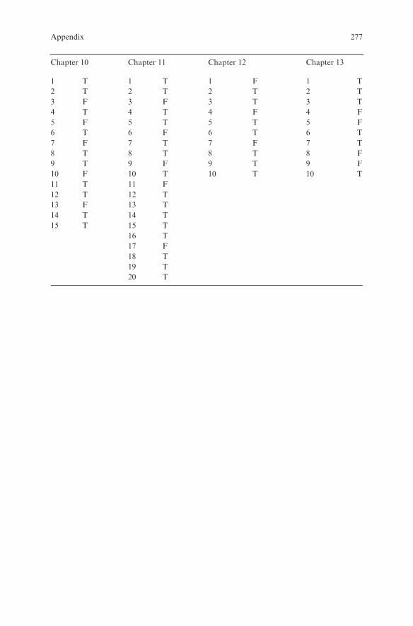
Chapter 10
1 T
2 T
3 F
4 T
5 F
6 T
7 F
8 T
9 T
10 F
11 T
12 T
13 F
14 T
15 T
Chapter 11
1 T
2 T
3 F
4 T
5 T
6 F
7 T
8 T
9 F
10 T
11 F
12 T
13 T
14 T
15 T
16 T
17 F
18 T
19 T
20 T
Chapter 12
1 F
2 T
3 T
4 F
5 T
6 T
7 F
8 T
9 T
10 T
Chapter 13
1 T
2 T
3 T
4 F
5 F
6 T
7 T
8 F
9 F
10 T
Appendix 277

Chapter 14
1 T
2 T
3 T
4 F
5 T
6 F
7 T
8 T
9 F
10 F
11 F
12 T
13 T
14 T
15 T
16 T
17 F
18 T
19 F
20 T
21 T
22 F
23 F
24 F
25 T
Chapter 15
1 T
2 F
3 F
4 T
5 T
6 T
7 T
8 T
9 T
10 T
11 F
12 T
13 F
14 T
15 T
16 T
17 T
18 F
19 F
20 T
21 T
22 T
23 F
24 T
25 T
26 T
27 F
28 T
29 T
30 F
Chapter 16
1 T 31 T
2 T 32 T
3 F 33 T
4 T 34 T
5 T 35 T
6 T 36 T
7 F 37 T
8 T 38 F
9 F 39 T
10 F 40 T
11 T 41 F
12 T 42 F
13 F 43 T
14 F 44 T
15 T 45 F
16 T 46 T
17 T 47 T
18 T 48 T
19 T 49 F
20 F 50 T
21 T 51 T
22 T 52 T
23 F 53 F
24 T 54 T
25 T 55 T
26 T
27 T
28 T
29 T
30 T
278 Appendix

Chapter 17
1 T
2 F
3 F
4 F
5 F
6 F
7 T
8 T
9 T
10 T
11 T
12 T
13 F
14 T
15 T
16 T
17 T
18 T
19 T
20 T
Chapter 18
1 T 26 T
2 T 27 F
3 F 28 T
4 F 29 T
5 T 30 F
6 T 31 F
7 F 32 T
8 F 33 T
9 F 34 T
10 F 35 F
11 T 36 F
12 F 37 F
13 T 38 T
14 T 39 T
15 F 40 T
16 F 41 T
17 T 42 T
18 T 43 T
19 T 44 T
20 F 45 T
21 T 46 F
22 F 47 T
23 F 48 T
24 F 49 T
25 F 50 T
Appendix 279
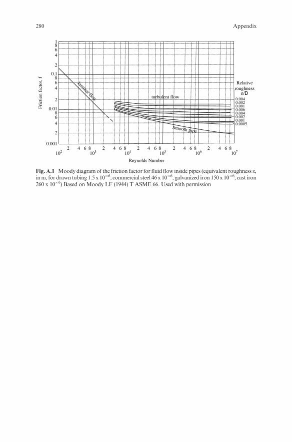
Fric
tion
fact
or, f
2
0.01
468
2
0.1
468
Smooth pipe
0.00050.0010.0020.0040.0060.0010.0020.004
Relativeroughness
ε/D
1071061051041031022 4 86 2 4 86 2 4 86 2 4 86 2 4 86
Reynolds Number
2
0.001
468
laminar flow turbulent flow
1
Fig. A.1 Moody diagramof the friction factor for fluid flow inside pipes (equivalent roughness e,inm, for drawn tubing 1.5 x 10�6, commercial steel 46 x 10�6, galvanized iron 150 x 10�6, cast iron260 x 10�6) Based on Moody LF (1944) T ASME 66. Used with permission
280 Appendix

Fig. A.2 Gurney-Lurie chart for a flat plate (1923) Ind Eng Chem 15. Used with permission
Appendix 281
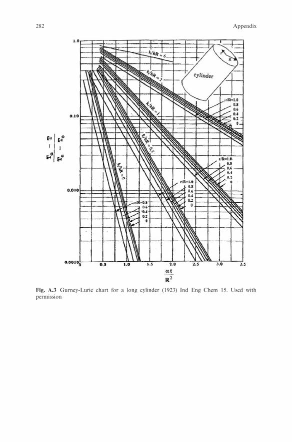
Fig. A.3 Gurney-Lurie chart for a long cylinder (1923) Ind Eng Chem 15. Used withpermission
282 Appendix
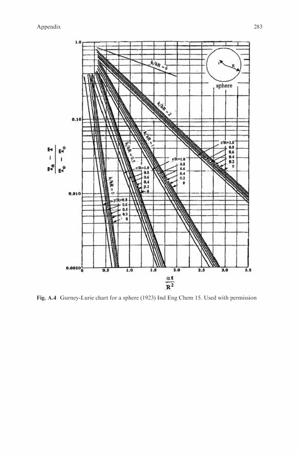
Fig. A.4 Gurney-Lurie chart for a sphere (1923) Ind Eng Chem 15. Used with permission
Appendix 283

Fig. A.5 Heisler chart for determining the midplane temperature of a flat plate (1947)T ASME 69. Used with permission
Fig. A.6 Heisler chart for determining the centerline temperature of a long cylinder (1947)T ASME 69. Used with permission
284 Appendix

Fig. A.7 Heisler chart for determining the center temperature of a sphere (1947) T ASME 69.Used with permission
Fig. A.8 Pressure- enthalpy diagram for HFC 134a with permission from DuPont
Appendix 285

Fig. A.9 Pressure- enthalpy diagram for HFC 404a with permission from DuPont
286 Appendix

Fig. A.10 Psychrometric chart with permission from Carrier
Appendix 287

Table A.1 Bessel functions J0(x) and J1(x)
x J0(x) J1(x)
0 1 0
0.2 0.9900 0.0995
0.4 0.9604 0.1960
0.6 0.9120 0.2867
0.8 0.8463 0.3688
1.0 0.7652 0.4401
1.2 0.6711 0.4983
1.4 0.5669 0.5419
1.6 0.4554 0.5699
1.8 0.3400 0.5815
2.0 0.2239 0.5767
2.2 0.1104 0.5560
2.4 0.0025 0.5202
2.4048 0.0000 0.5192
2.6 �0.0968 0.4708
2.8 �0.1850 0.4097
3.0 �0.2601 0.3391
3.2 �0.3202 0.2613
3.4 �0.3643 0.1792
3.6 �0.3918 0.0955
3.8 �0.4026 0.0128
4.0 �0.3971 �0.06604.2 �0.3766 �0.13864.4 �0.3423 �0.20284.6 �0.2961 �0.25664.8 �0.2404 �0.29855.0 �0.1776 �0.32765.2 �0.1103 �0.34325.4 �0.0412 �0.34535.5201 0.0000 �0.34035.6 0.0270 �0.33435.8 0.0917 �0.31106.0 0.1506 �0.27676.2 0.2017 �0.23296.4 0.2433 �0.18166.6 0.2740 �0.12506.8 0.2931 �0.06527.0 0.3001 �0.00477.2 0.2951 0.0543
7.4 0.2786 0.1096
7.6 0.2516 0.1592
7.8 0.2154 0.2014
8.0 0.1717 0.2346
8.2 0.1222 0.2580
8.4 0.0692 0.2708
8.6 0.0146 0.2728
288 Appendix
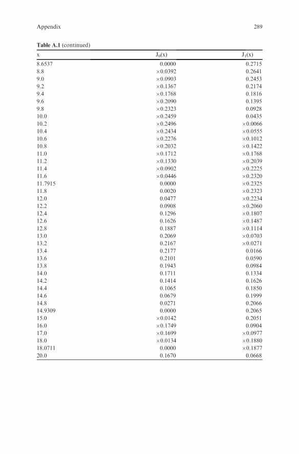
Table A.1 (continued)
x J0(x) J1(x)
8.6537 0.0000 0.2715
8.8 �0.0392 0.2641
9.0 �0.0903 0.2453
9.2 �0.1367 0.2174
9.4 �0.1768 0.1816
9.6 �0.2090 0.1395
9.8 �0.2323 0.0928
10.0 �0.2459 0.0435
10.2 �0.2496 �0.006610.4 �0.2434 �0.055510.6 �0.2276 �0.101210.8 �0.2032 �0.142211.0 �0.1712 �0.176811.2 �0.1330 �0.203911.4 �0.0902 �0.222511.6 �0.0446 �0.232011.7915 0.0000 �0.232511.8 0.0020 �0.232312.0 0.0477 �0.223412.2 0.0908 �0.206012.4 0.1296 �0.180712.6 0.1626 �0.148712.8 0.1887 �0.111413.0 0.2069 �0.070313.2 0.2167 �0.027113.4 0.2177 0.0166
13.6 0.2101 0.0590
13.8 0.1943 0.0984
14.0 0.1711 0.1334
14.2 0.1414 0.1626
14.4 0.1065 0.1850
14.6 0.0679 0.1999
14.8 0.0271 0.2066
14.9309 0.0000 0.2065
15.0 �0.0142 0.2051
16.0 �0.1749 0.0904
17.0 �0.1699 �0.097718.0 �0.0134 �0.188018.0711 0.0000 �0.187720.0 0.1670 0.0668
Appendix 289
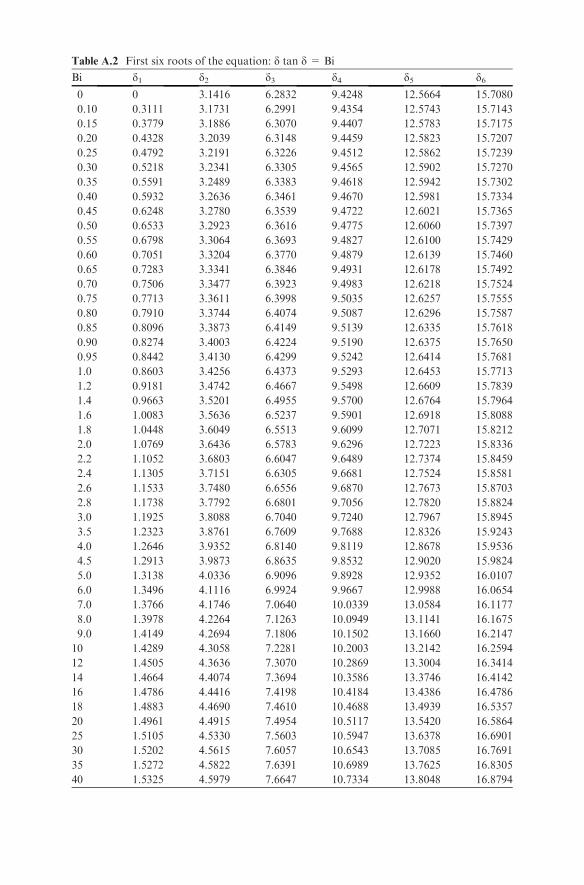
Table A.2 First six roots of the equation: d tan d = Bi
Bi d1 d2 d3 d4 d5 d60 0 3.1416 6.2832 9.4248 12.5664 15.7080
0.10 0.3111 3.1731 6.2991 9.4354 12.5743 15.7143
0.15 0.3779 3.1886 6.3070 9.4407 12.5783 15.7175
0.20 0.4328 3.2039 6.3148 9.4459 12.5823 15.7207
0.25 0.4792 3.2191 6.3226 9.4512 12.5862 15.7239
0.30 0.5218 3.2341 6.3305 9.4565 12.5902 15.7270
0.35 0.5591 3.2489 6.3383 9.4618 12.5942 15.7302
0.40 0.5932 3.2636 6.3461 9.4670 12.5981 15.7334
0.45 0.6248 3.2780 6.3539 9.4722 12.6021 15.7365
0.50 0.6533 3.2923 6.3616 9.4775 12.6060 15.7397
0.55 0.6798 3.3064 6.3693 9.4827 12.6100 15.7429
0.60 0.7051 3.3204 6.3770 9.4879 12.6139 15.7460
0.65 0.7283 3.3341 6.3846 9.4931 12.6178 15.7492
0.70 0.7506 3.3477 6.3923 9.4983 12.6218 15.7524
0.75 0.7713 3.3611 6.3998 9.5035 12.6257 15.7555
0.80 0.7910 3.3744 6.4074 9.5087 12.6296 15.7587
0.85 0.8096 3.3873 6.4149 9.5139 12.6335 15.7618
0.90 0.8274 3.4003 6.4224 9.5190 12.6375 15.7650
0.95 0.8442 3.4130 6.4299 9.5242 12.6414 15.7681
1.0 0.8603 3.4256 6.4373 9.5293 12.6453 15.7713
1.2 0.9181 3.4742 6.4667 9.5498 12.6609 15.7839
1.4 0.9663 3.5201 6.4955 9.5700 12.6764 15.7964
1.6 1.0083 3.5636 6.5237 9.5901 12.6918 15.8088
1.8 1.0448 3.6049 6.5513 9.6099 12.7071 15.8212
2.0 1.0769 3.6436 6.5783 9.6296 12.7223 15.8336
2.2 1.1052 3.6803 6.6047 9.6489 12.7374 15.8459
2.4 1.1305 3.7151 6.6305 9.6681 12.7524 15.8581
2.6 1.1533 3.7480 6.6556 9.6870 12.7673 15.8703
2.8 1.1738 3.7792 6.6801 9.7056 12.7820 15.8824
3.0 1.1925 3.8088 6.7040 9.7240 12.7967 15.8945
3.5 1.2323 3.8761 6.7609 9.7688 12.8326 15.9243
4.0 1.2646 3.9352 6.8140 9.8119 12.8678 15.9536
4.5 1.2913 3.9873 6.8635 9.8532 12.9020 15.9824
5.0 1.3138 4.0336 6.9096 9.8928 12.9352 16.0107
6.0 1.3496 4.1116 6.9924 9.9667 12.9988 16.0654
7.0 1.3766 4.1746 7.0640 10.0339 13.0584 16.1177
8.0 1.3978 4.2264 7.1263 10.0949 13.1141 16.1675
9.0 1.4149 4.2694 7.1806 10.1502 13.1660 16.2147
10 1.4289 4.3058 7.2281 10.2003 13.2142 16.2594
12 1.4505 4.3636 7.3070 10.2869 13.3004 16.3414
14 1.4664 4.4074 7.3694 10.3586 13.3746 16.4142
16 1.4786 4.4416 7.4198 10.4184 13.4386 16.4786
18 1.4883 4.4690 7.4610 10.4688 13.4939 16.5357
20 1.4961 4.4915 7.4954 10.5117 13.5420 16.5864
25 1.5105 4.5330 7.5603 10.5947 13.6378 16.6901
30 1.5202 4.5615 7.6057 10.6543 13.7085 16.7691
35 1.5272 4.5822 7.6391 10.6989 13.7625 16.8305
40 1.5325 4.5979 7.6647 10.7334 13.8048 16.8794
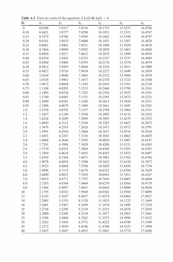
Table A.3 First six roots of the equation: d J1(d)-Bi J0(d) = 0
Bi d1 d2 d3 d4 d5 d60 0.0348 3.8317 7.0156 10.1735 13.3237 16.4706
0.10 0.4421 3.8577 7.0298 10.1833 13.3312 16.4767
0.15 0.5375 3.8706 7.0369 10.1882 13.3349 16.4797
0.20 0.6181 3.8835 7.0440 10.1931 13.3387 16.4828
0.25 0.6861 3.8963 7.0511 10.1980 13.3424 16.4858
0.30 0.7464 3.9090 7.0582 10.2029 13.3462 16.4888
0.35 0.8026 3.9217 7.0652 10.2078 13.3499 16.4919
0.40 0.8524 3.9343 7.0723 10.2127 13.3537 16.4949
0.45 0.8984 3.9469 7.0793 10.2176 13.3574 16.4979
0.50 0.9412 3.9593 7.0864 10.2224 13.3611 16.5009
0.55 0.9812 3.9716 7.0934 10.2272 13.3649 16.5039
0.60 1.0184 3.9840 7.1003 10.2322 13.3686 16.5070
0.65 1.0538 3.9963 7.1073 10.2370 13.3723 16.5100
0.70 1.0872 4.0084 7.1143 10.2419 13.3761 16.5130
0.75 1.1196 4.0205 7.1213 10.2468 13.3798 16.5161
0.80 1.1495 4.0324 7.1282 10.2516 13.3835 16.5191
0.85 1.1780 4.0443 7.1351 10.2565 13.3872 16.5221
0.90 1.2049 4.0561 7.1420 10.2613 13.3910 16.5251
0.95 1.2309 4.0678 7.1489 10.2661 13.3947 16.5281
1.0 1.2558 4.0795 7.1557 10.2709 13.3984 16.5311
1.2 1.3457 4.1249 7.1830 10.2902 13.4132 16.5432
1.4 1.4226 4.1689 7.2099 10.3093 13.4279 16.5552
1.6 1.4892 4.2112 7.2364 10.3283 13.4427 16.5672
1.8 1.5476 4.2519 7.2626 10.3471 13.4573 16.5791
2.0 1.5991 4.2910 7.2884 10.3657 13.4718 16.5910
2.2 1.6451 4.3287 7.3136 10.3843 13.4863 16.6029
2.4 1.6868 4.3644 7.3385 10.4026 13.5007 16.6147
2.6 1.7241 4.3988 7.3629 10.4208 13.5151 16.6265
2.8 1.7579 4.4318 7.3868 10.4388 13.5293 16.6382
3.0 1.7884 4.4634 7.4103 10.4565 13.5433 16.6497
3.5 1.8545 4.5364 7.4671 10.5001 13.5782 16.6786
4.0 1.9078 4.6019 7.5200 10.5422 13.6124 16.7072
4.5 1.9523 4.6604 7.5704 10.5829 13.6459 16.7354
5.0 1.9898 4.7133 7.6178 10.6222 13.6784 16.7629
6.0 2.0490 4.8033 7.7039 10.6963 13.7413 16.8167
7.0 2.0935 4.8771 7.7797 10.7645 13.8007 16.8684
8.0 2.1285 4.9384 7.8464 10.8270 13.8566 16.9178
9.0 2.1566 4.9897 7.9051 10.8842 13.9090 16.9650
10 2.1795 5.0332 7.9569 10.9363 13.9580 17.0099
12 2.2147 5.1027 8.0437 11.0274 14.0464 17.0927
14 2.2405 5.1555 8.1128 11.1035 14.1232 17.1669
16 2.2601 5.1967 8.1689 11.1674 14.1898 17.2329
18 2.2756 5.2298 8.2150 11.2215 14.2478 17.2918
20 2.2880 5.2568 8.2534 11.2677 14.2983 17.3441
25 2.3108 5.3068 8.3262 11.3575 14.3996 17.4522
30 2.3262 5.3410 8.3771 11.4222 14.4749 17.5349
35 2.3372 5.3659 8.4146 11.4706 14.5323 17.5994
40 2.3455 5.3847 8.4432 11.5081 14.5774 17.6508
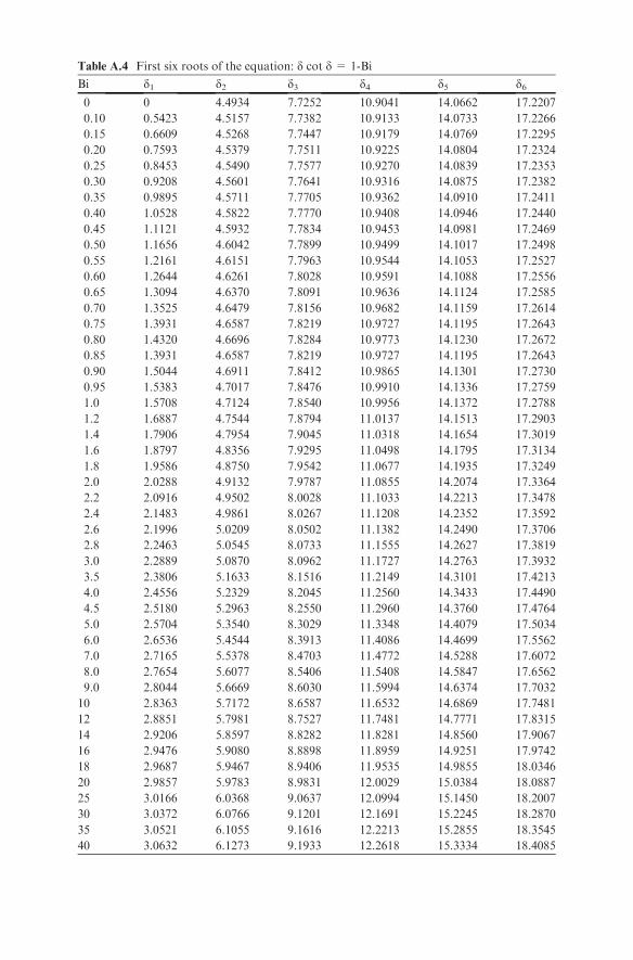
Table A.4 First six roots of the equation: d cot d = 1-Bi
Bi d1 d2 d3 d4 d5 d60 0 4.4934 7.7252 10.9041 14.0662 17.2207
0.10 0.5423 4.5157 7.7382 10.9133 14.0733 17.2266
0.15 0.6609 4.5268 7.7447 10.9179 14.0769 17.2295
0.20 0.7593 4.5379 7.7511 10.9225 14.0804 17.2324
0.25 0.8453 4.5490 7.7577 10.9270 14.0839 17.2353
0.30 0.9208 4.5601 7.7641 10.9316 14.0875 17.2382
0.35 0.9895 4.5711 7.7705 10.9362 14.0910 17.2411
0.40 1.0528 4.5822 7.7770 10.9408 14.0946 17.2440
0.45 1.1121 4.5932 7.7834 10.9453 14.0981 17.2469
0.50 1.1656 4.6042 7.7899 10.9499 14.1017 17.2498
0.55 1.2161 4.6151 7.7963 10.9544 14.1053 17.2527
0.60 1.2644 4.6261 7.8028 10.9591 14.1088 17.2556
0.65 1.3094 4.6370 7.8091 10.9636 14.1124 17.2585
0.70 1.3525 4.6479 7.8156 10.9682 14.1159 17.2614
0.75 1.3931 4.6587 7.8219 10.9727 14.1195 17.2643
0.80 1.4320 4.6696 7.8284 10.9773 14.1230 17.2672
0.85 1.3931 4.6587 7.8219 10.9727 14.1195 17.2643
0.90 1.5044 4.6911 7.8412 10.9865 14.1301 17.2730
0.95 1.5383 4.7017 7.8476 10.9910 14.1336 17.2759
1.0 1.5708 4.7124 7.8540 10.9956 14.1372 17.2788
1.2 1.6887 4.7544 7.8794 11.0137 14.1513 17.2903
1.4 1.7906 4.7954 7.9045 11.0318 14.1654 17.3019
1.6 1.8797 4.8356 7.9295 11.0498 14.1795 17.3134
1.8 1.9586 4.8750 7.9542 11.0677 14.1935 17.3249
2.0 2.0288 4.9132 7.9787 11.0855 14.2074 17.3364
2.2 2.0916 4.9502 8.0028 11.1033 14.2213 17.3478
2.4 2.1483 4.9861 8.0267 11.1208 14.2352 17.3592
2.6 2.1996 5.0209 8.0502 11.1382 14.2490 17.3706
2.8 2.2463 5.0545 8.0733 11.1555 14.2627 17.3819
3.0 2.2889 5.0870 8.0962 11.1727 14.2763 17.3932
3.5 2.3806 5.1633 8.1516 11.2149 14.3101 17.4213
4.0 2.4556 5.2329 8.2045 11.2560 14.3433 17.4490
4.5 2.5180 5.2963 8.2550 11.2960 14.3760 17.4764
5.0 2.5704 5.3540 8.3029 11.3348 14.4079 17.5034
6.0 2.6536 5.4544 8.3913 11.4086 14.4699 17.5562
7.0 2.7165 5.5378 8.4703 11.4772 14.5288 17.6072
8.0 2.7654 5.6077 8.5406 11.5408 14.5847 17.6562
9.0 2.8044 5.6669 8.6030 11.5994 14.6374 17.7032
10 2.8363 5.7172 8.6587 11.6532 14.6869 17.7481
12 2.8851 5.7981 8.7527 11.7481 14.7771 17.8315
14 2.9206 5.8597 8.8282 11.8281 14.8560 17.9067
16 2.9476 5.9080 8.8898 11.8959 14.9251 17.9742
18 2.9687 5.9467 8.9406 11.9535 14.9855 18.0346
20 2.9857 5.9783 8.9831 12.0029 15.0384 18.0887
25 3.0166 6.0368 9.0637 12.0994 15.1450 18.2007
30 3.0372 6.0766 9.1201 12.1691 15.2245 18.2870
35 3.0521 6.1055 9.1616 12.2213 15.2855 18.3545
40 3.0632 6.1273 9.1933 12.2618 15.3334 18.4085

Table A.5 Error function
x erf (x) erfc (x)
0 0 1
0.05 0.056372 0.943628
0.10 0.112463 0.887537
0.15 0.167996 0.832004
0.20 0.222703 0.777297
0.25 0.276326 0.723674
0.30 0.328627 0.671373
0.35 0.379382 0.620618
0.40 0.428392 0.571608
0.45 0.475482 0.524518
0.50 0.520500 0.479500
0.55 0.563323 0.436677
0.60 0.603856 0.396144
0.65 0.642029 0.357971
0.70 0.677801 0.322199
0.75 0.711155 0.288845
0.80 0.742101 0.257899
0.85 0.770668 0.229332
0.90 0.796908 0.203092
0.95 0.820891 0.179109
1.0 0.842701 0.157299
1.1 0.880205 0.119795
1.2 0.910314 0.089686
1.3 0.934008 0.065992
1.4 0.952285 0.047715
1.5 0.966105 0.033895
1.6 0.976348 0.023652
1.7 0.983790 0.016210
1.8 0.989091 0.010909
1.9 0.992790 0.007210
2.0 0.995322 0.004678
2.1 0.997021 0.002979
2.2 0.998137 0.001863
2.3 0.998857 0.001143
2.4 0.999311 0.000689
2.5 0.999593 0.000407
2.6 0.999764 0.000236
2.7 0.999866 0.000134
2.8 0.999925 0.000075
2.9 0.999959 0.000041
3.0 0.999978 0.000022
Appendix 293
Index
Air conditioning, 249
Bessel functions, 102–103, 109, 111,288, 289
Biot numberheat transfer, 102–104, 108–140mass transfer, 163
Breadheat transfer in, 86, 100water activity of, 198
Cheese, diffusion of NaCl, 170, 178Clostridium botulinum, 181–182CO2, cryogenic fluid, 209Colebrook equation, 45, 49Concentration
boundary layer, 156evaporation, 215–236material balance, 12–16unsteady-state mass transfer,
163–180Conduction of heat
steady state, 55–66unsteady state, 101–140
Convection of heat, 67–94forced, 68–76free, 77–79, 83
Cookie, baking of, 98Cooling
of a can, 188coil, 249evaporative of lettuce, 9, 194forced-air, 135hydrocooling, 126, 136load, 195, 208, 209Newton’s law of, 68room, 135section of pasteurizer, 89
Cucumber, diffusion of NaCl in, 174–176
Cylindersteady state heat conduction, 55, 58, 60unsteady state heat conduction, 102–104,
107–113, 123–126, 132–134unsteady state mass transfer, 163–165,
174–176
Decimal reduction time, 181–191Dew-point, 237–243Diffusion
of NaCl in cucumber, 174–176of NaCl in feta cheese, 170–174steady state, 141–154
Distillation, flash, 24Dryer
belt, 254, 266heat losses in, 82, 85solar, 100spray, 156, 158, 254–255, 272tray, 255, 260, 264tunnel, 254, 270
Dry ice, 209Drying
air recirculation in, 267constant rate period, 253–255, 257–258,
260–262falling rate period, 254, 257, 258, 265rate curve, 257time calculation, 258–260, 265
Energy balances, 21–31Error function, 102–103, 120, 128, 170, 177, 293Evaporation, 215–236Evaporator
double-effect backward, 232double-effect forward, 220, 230four effect backward, 235four effect forward, 234single effect, 217, 225, 226, 228
295
Fanning equation, 42, 49Feta cheese, diffusion of NaCl in, 170–174Fish, freezing, 211Fluid flow, 33–40
friction losses in, 44, 45, 51of honey, 38of non-Newtonian fluids, 37, 38, 40of olive oil, 37pressure drop in, 35, 49Reynolds number in, 35, 36, 37, 51of tomato concentrate, 38velocity distribution in, 40
Fourier’s law, 56, 64Fourier number in heat transfer, 101,
105–127Fourier number in mass transfer, 163–176Freezing, 193–214
freezing load, 200, 211Cleland and Earle’s modification, 202freezing time calculation, 201–208,
212–213Pham’s modification, 205, 212Plank’s equation, 201, 202Plank number, 203Stefan number, 203
Frictionlosses in fluids, 44, 45, 51
F-value, 181–191
Glucosesyrup, heating of, 129syrup, mass balance in, 18
Grashof numberin heat transfer, 68, 69, 77, 79, 83in mass transfer, 160
Gurney-Lurie chart, 104, 109–127, 281–283
Hagen-Poiseuille equation, 34, 35, 37, 38Head
developed head by a pump, 42, 43, 46net positive suction head, 41, 46
Heat exchangers, 69calculations in, 86, 88, 90, 94effectiveness of, 87
Heat transfer coefficient, 67–69calculation, 71–81overall, 68, 81–85radiation, 97
Heisler chart, 104, 109–127, 284, 285Holding tube, 90, 92, 182Honey
crystallization of, 17viscosity determination of, 38
Humid heat, 237, 238, 242, 247, 248, 261Humidity
humidity ratio, 237–251, 260–263, 267relative humidity, 237–251
Humid volume, 237, 238, 241–251, 263, 269
Lewis number, 156
Mass balance, 11–20, 25, 28, 29evaporator, 218, 222, 223, 227, 231honey, 17marmalade, 19milk, 16olive oil, 19orange juice, 12, 15sugar syrup, 14
Mechanical energy balance equation, 41, 42,46, 50, 52
Milkcanned concentration, 16concentration of, 233heating of, 22pasteurization of, 90spray dried, 272standardization of, 19sterilization of, 28, 120substrate for yogurt culture, 190
Moody diagram, 42, 43, 49, 280
Newtonian and Non-Newtonian fluids, 33,34, 37, 39, 40
Nusselt number, 68calculation of, 71–83
Olive oil, 19, 37Oven, heat transfer losses, 59
Packaging, mass transfer in, 145–148,151–153
Pasteurization, 181–191Pasteurizer, heat transfer calculations, 90Permeability, gas, 142–143, 146–148,
151–153Potato
drying of, 266heat transfer in, 140packaging of chips, 153
Prandtl number, use of, 68–84Pressure drop calculations, 33, 35, 37–40, 42,
48, 49, 53Psychrometrics, 237–252Psychrometric chart, 287
296 Index
Pumpdeveloped head, calculation, 46, 53mechanical energy balance equation, 41,
42, 46, 50, 52,net positive suction head, 42, 47, 54Selection, 48
Radiation, heat transfer by, 95–100heat transfer coefficient, 97
Refrigerant chartsHFC,134a, 285HFC 404A, 286
Refrigeration, 193–198, 208, 209COP, 198load, 194–195, 209mechanical refrigeration system, 196
Reynolds numberin fluid flow calculations, 33–40in heat transfer calculations, 67–84in mass transfer calculations, 155–162
Riedel chart, 201
Schmidt number, 155–162Schwartzberg’s equation, 200, 203, 204, 211Semi-infinite body
unsteady state heat transfer, 104,127–128, 137–139
unsteady state mass transfer, 163,176–177
Sherwood number, 155–162Slab
unsteady state diffusion, 165–174,177–180
unsteady state heat conduction, 102–107,113–119, 130–132, 134–135
Soil, moisture transfer in, 176–177Sphere
unsteady state heat conduction, 102–104,121–123, 126–127
Steam infusion sterilizer, 28Sterilization, 181–191Sulfur dioxide, transfer in apple slice,
168–169
Temperaturedew-point, 237–243sky, 99–100wet bulb, 237–243, 254, 255, 261, 263, 266
Thermal processing, see Pasteurization;Sterilization
Thermos, heat losses in, 97–98Tomato
flow of concentrate, 38–40juice, concentration of, 215, 220paste, drying of, 260transient heating of, 139
Unitsbasic and derived, 1conversion, 2–4
Velocity calculation in fluid flow, 35–40Viscosity measurement, 38Vitamin thermal destruction, 184–187
Water vapor permeability, 142Water vapor transmission rate, 146–148
Z value, 181–191
Index 297