solution for automotive - mrc gigacomp › pdfs › amotech-antennas... · antenna line-up...
TRANSCRIPT

AMOTECH
→
SOLUTION FOR
AUTOMOTIVE
CONFIDENTIALCopyright 201у. AMOTECH Co., Ltd. all rights reserved.

AMO GROUP
AMO
SENSE
AMO
TECH
AMOGREENTECH
Incheon, South Korea
8 sites (5 in Korea & 2 in China & 1 in Vietnam)
11 locations in worldwide
6 centers (3 in Korea & 3 in China)
KOSDAQ-published in 2003 (Established in 1994)
$180M(2014) → $320M(2015) → $330M(2016) → $360M(2017)
Antenna division
Head office
Factory
Sales office
R&D center
Type
Sales revenue

FACTORY
QINGDAO
KOREACHINA
INCHEON
Antenna Passive Components
HASUNG
Amorphous core
SUCHAM
HTF Nano fiber membrane Air vent
POSEUNG
Shielding sheet WPC BLDC motor
CHOENAN
LED substrate Module Lightening
Motor Antenna (GPS) WPC
VIETNAM
VINHYEN
Antenna (NFC)
SHANDONG

COMPETITIVENESS
• No. 1 market share : NFC antenna
• Support customers to pass certificate
• EMVCo / ISO (for European market)
• Felica (for Japanese market)
• ISIS (for USA market)
• NFC forum, ISO (for Chinese market)
• All credit card (Visa, Master, Discover)
• Biggest capacity
• Fully equipped test bench
• Automation measuring machine
• In-house material
→ Flexibility in material composition
• Ferrite sheet
• Glass metal sheet
• Hybrid sheet
• Various certificate experience
• Customized design
• Co-design with chipset maker
• R&D manpower : 12%
Antenna
core competence
▪ Chipset
▪ Certificate

CUSTOMIZED DESIGN
Concept
Design
Proto
PP
MP
Information & Guide
Guide & Report
Concept
Customized
design
Approve
MP
Approval
Customer AMO
Items Tool
EM simulation
HFSS
CST
SEMCAD
PCB designCADSTAR
ALTIUM
Mechanical design
AUTOCAD
SOLIDWORKS
RHINO
Design guide
Simulation
Optimization
Measurement
- Gain & Efficiency
- Isolation
- Radiation pattern
- OTA (TRP/TIS)
▶ Simulation Tools
▶ Major Process
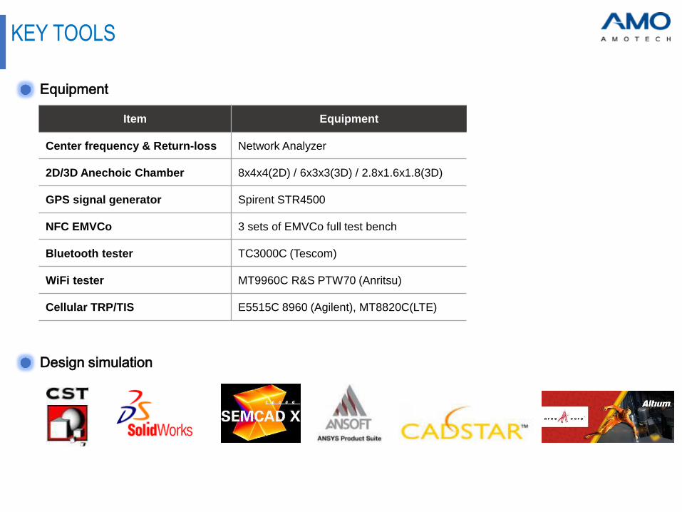
KEY TOOLS
Item Equipment
Center frequency & Return-loss Network Analyzer
2D/3D Anechoic Chamber 8x4x4(2D) / 6x3x3(3D) / 2.8x1.6x1.8(3D)
GPS signal generator Spirent STR4500
NFC EMVCo 3 sets of EMVCo full test bench
Bluetooth tester TC3000C (Tescom)
WiFi tester MT9960C R&S PTW70 (Anritsu)
Cellular TRP/TIS E5515C 8960 (Agilent), MT8820C(LTE)
Equipment
Design simulation

DESIGN SERVICE
Custom antenna design &
Device layout optimization
1. 2. 3.
Capability of electro magne-
tic simulationAntenna co-existence test
▲ Monopole ▲ PIFA
▲ cable assembly

MEASUREMENT
1.
3. 4.
5.
2.
Test No. #1-1
Antenna AMAN301512ST01
Series 1.8nH
Shunt N/C
GND 1.0nH
Freq.
(MHz)
Efficiency
(%)
Avg. gain
(dBi)
Peak gain
(dBi)
2400 MHz 65.21 -1.86 3.15
2442 MHz 69.58 -1.58 3.11
2485 MHz 61.22 -2.13 2.97
Matching information Passive result : VSWR / Smith chart
Passive antenna 2D / 3D radiation pattern
Active measurement
Passive antenna gain
※ AMOTECH measurement
√ To provide test report including No. 1 ~ 5
√ To ensure the customer achieve target spec.

For AVN / Infotainment ▪ Bluetooth antenna
▪ WiFi antenna
▪ NFC antenna
For Telematics (e-call)▪ GNSS(GPS / GLONASS / Beidou) antenna
▪ WiFi antenna
▪ Bluetooth antenna
▪ 3G/4G antenna
For Wireless charging▪ Coil + sheet
▪ Thermal sheet
For car sharing ▪ NFC antenna
▪ GPS antenna
For V2X ▪ 5.9GHz antenna
For Shark antenna▪ GNSS (GPS / GLONASS / Beidou) antenna
▪ SDARS antenna
For Smart entry / Key fob▪ LF antenna
▪ 433MHz antenna
▪ NFC antenna
For BCM / SMK / IBU▪ 433MHz antenna
TOTAL SOLUTION

ANTENNA TREND
• Conventional type
• New type_1
- Shark fin + TCU
• New type_2
- No shark fin
TCU
Shark fin
SDARS
(SXM)
L1+L2
LTE1
LTE2
LTE3
LTE4
V2X
BT/WiFiBT/WiFi
▪ Shark fin

ANTENNA TREND
AudioAV
(Audio + Video)
AVN
(AV + Navigation)CID/AVN
∙ Bluetooth ∙ Bluetooth
* Chip / PCB pattern
∙ BT / WiFi / MIMO
* Chip / PCB pattern
∙ Display : 7~8inch
∙ BT / WiFi / MIMO / NFC
* Cable assembly
∙ Display : Over 12inch
▪ Navigation transition
▪ NFC embedded technology

ANTENNA LINE-UP
Frequency(MHz)
Bluetooth
WiFi
GPS
WiFi Dual
850, 900 MHz 1,710~2,170 MHz
1,575 MHz
2,450 MHz
704 MHz 2,690 MHz
2,450 / 5,800 MHz
1,559~1,609MHz 2,450 MHz
868 / 915
NFC
13.56 MHz
NFMI
10.579 MHz
ISM
LTE (LTE, GSM, WCDMA)
GSM (GSM, DCS, PCS, UMTS)
GPS / GLONASS / BEIDOU / GALILEO
10.57 13.56 433 704~716 850~960 1,575 1,609 1,710 1,900 2,170 2,450 2,690 5,800
ISM
433

VARIOUS TYPES OF ANTENNAS
GPS
LTE
ISM
Bluetooth
WiFi
Chip
FPCB
PCB+cable
Patch
PCB+cable
Metal
stamping
Carrier
Chip
FPCB
PCB+cable
Carrier
PCB+cable
Chip
Enclosure
Chip
NFC
FPCB
ChipA broad range of
materials
Patch

TELEMATICS / E-CALL
eCall system mandatory for all cars sold in
the EU from Mar. 31, 2018.
Emergency call center Targeted, faster help at
Scene of accident
Notification
forwarding
Cellular :
Chip / PCB + cable assembly
GNSS :
GPS / GLONASS / BEIDOU / GALILEO
Bluetooth & WiFi :
SMD chip

OBD / UBI
Cellular :
Chip / PCB + cable assembly
GNSS :
GPS / GLONASS
Bluetooth & WiFi :
SMD chip
∙ OBD : On Board Diagnosis∙ UBI : Usage Based Insurance∙ TSP : Telecom Service Platform
UBITSP
OBD
Internet TCP/IPGPSTCP/IP

Conventional AMOTECH
BCM - Body Control Module
Body
Control
ModuleUHF
LF
▪ LF antenna
▪ UHF antenna▲ Vehicle test_AMOTECH chip antenna
• Competitive price
• SMT
• Equivalent performance
LF

PATCH ANTENNA DESIGNSGNSS / SDARS
02
Shark fin
03
GNSS module
01
E-call
04
Shark fin
15
GNSS module

PATCHPassive antenna overview
GNSS
(GPS L1 / Glonass/ Galileo
/ Beidou)
GPS L1
+
Glonass
GPS L1
+
GPS L2
SXM
with
air gap
SXM
with 2nd
radiator
GPS
+
SXM
GPS
+
SXM
SDARS
(SXM)
GNSS
+
SXM
With single feed With dual feed25x25-6TDia.42-6T
34x34-3T
35x33-6T
25x25 + 34x34
18x18 + 25x25
GPS L1+
GPS L2+
GPS L5

PATCHStacked Patch Antenna GNSS L1 + L2 Solutions
High perform 42x13mmASPA-A35A
• GNSS L1 (1559~1608MHz)
• GNSS L2 (1215~1255MHz)
• Size : Dia. 42-13T
- GNSS L1 (Dia. 42-4T)
- GNSS L2 (Dia. 42-8T)
Slim 42x8mmASPA-A36A
• GNSS L1 (1559~1608MHz)
• GNSS L2 (1215~1255MHz)
• Size : Dia. 42-8T
- GNSS L1 (Dia. 42-3T)
- GNSS L2 (Dia.42-4T)
Small 33x15mmASPA-A37A
• GNSS L1 (1559~1608MHz)
• GNSS L2 (1215~1255MHz)
• Size
- GNSS L1 (25x25-6T)
- GNSS L2 (33x33-8T)
Peak Gain [dBic] 3.2~4.4
Axial Ratio [dB] 0.7~1.3
Isolation [dB] Min. 23.50
Peak Gain [dBic] 2.2~4.3
Axial Ratio [dB] 1.2~1.5
Isolation [dB] Min. 22.23
Peak Gain [dBic] -1.5~1.0
Axial Ratio [dB] 1.8~3.2
Isolation [dB] Min. 20.63
Peak Gain [dBic] 3.2~4.4
Axial Ratio [dB] 1.0~1.5
Isolation [dB] Min. 33.96
Peak Gain [dBic] 0.7~4.0
Axial Ratio [dB] 0.9~2.7
Isolation [dB] Min. 23.4
Peak Gain [dBic] 3.1~5.0
Axial Ratio [dB] 1.2~1.8
Isolation [dB] Min. 17.9

▪ Requirement check :
GNSS L1 :
L1 : 4dBic @1565.42~1585.42MHz
G1 : 2.5dBic @1599~1619MHz
B1 : ?dBic @1559.098~1563.098MHz
E1 : 4dBic @1609MHz and 1558~1592MHz
PATCHStacked Patch Antenna GNSS L1 + L2 + L5
▲ GNSS L1 : Dia.42-6TGNSS L2/L5 : 50x50-4.8T• Case2 : GNSS L1(Dia.42-4T) / GNSS L2/L5 (Dia. 42-8T)
Band PerformanceG/P
1,000mm
G/P
150mm
GNSS L1
1525~1608M
Zenith Gain [dBic] 0.5~4.2 3.5~5.4
Axial Ratio [dB] 1.5~2.5 1.6~2.5
GNSS L2/l5
1164~1255M
Zenith Gain [dBic] -3.7~1.2 0~4.5
Axial Ratio [dB] 1.5~2.0 1.4~2.0
▲ GNSS L1 : Dia.42-4T)GNSS L2/L5 : Dia. 42-8T
• Case1 : GNSS L1(Dia.42-6T) / GNSS L2&L5(50x50-4.8T)
GNSS L2 :
L2 : 4dBic @1217.6~1237.6MHz
G2 : 2.5dBic @1242~1262MHz
B2 : 2.5dBic @1197.14~1217.14MHz
GNSS L5 :
L5 : -1.5dBic @1166.45~1186.45MHz
E5 : -1.5dBic @1177~1207MHz
Band PerformanceG/P
1,000mm
G/P
150mm
GNSS L1
1558~1619M
Zenith Gain [dBic] - 3.2~4.9
Axial Ratio [dB] - Max. 2.5
GNSS L2/l5
1166~1262M
Zenith Gain [dBic] - -2.4~4.0
Axial Ratio [dB] - Max. 2.5

PATCHGNSS L1+L2+Inmarsat SBAS(ASPA-A57A) - High Performance 50x17mm
GNSS L1+Inmarsat (Dia. 46-8T) / GNSS L2 (50x50x8mm) Ground plane dia. : 150mm
GNSS L1
1559~1608MHz
Peak Gain [dBic] 5.3~5.9
Axial Ratio [dB] Max. 1.4
GNSS L2
1194~1255MHz
Peak Gain [dBic] 2.5~5.6
Axial Ratio [dB] Max. 2.9
INMARSAT
1525~1550MHz
Peak Gain [dBic] 4.5~5.5
Axial Ratio [dB] Max. 2.3
Theta(Θ)Gain @ GNSS L1 + Inmarsat
1525 1535 1540 1545 1550 1559 1561 1563 1565 1570 1575 1580 1585 1592 1595 1599 1608 1610
0 4.50 4.90 5.02 5.55 5.55 5.54 5.52 5.51 5.59 5.63 5.63 5.63 5.76 5.85 5.90 5.77 5.51 5.33
10 4.35 4.74 4.87 5.30 5.31 5.28 5.25 5.26 5.33 5.42 5.43 5.45 5.59 5.65 5.72 5.54 5.27 5.08
20 3.82 4.25 4.35 4.84 4.84 4.81 4.77 4.78 4.85 4.89 4.91 4.91 5.00 5.04 5.06 4.87 4.59 4.41
30 3.00 3.49 3.62 4.11 4.09 4.09 4.06 4.05 4.10 4.14 4.14 4.10 4.17 4.23 4.20 4.02 3.66 3.47
40 1.99 2.46 2.61 3.12 3.10 3.08 3.05 3.04 3.11 3.17 3.18 3.15 3.24 3.29 3.27 3.03 2.62 2.41
50 0.56 1.12 1.30 1.74 1.75 1.74 1.67 1.68 1.74 1.81 1.80 1.80 1.85 1.87 1.87 1.63 1.29 1.09
60 -0.97 -0.45 -0.29 0.22 0.19 0.22 0.18 0.16 0.27 0.26 0.32 0.31 0.39 0.42 0.42 0.20 -0.23 -0.43
70 -2.61 -2.04 -1.94 -1.42 -1.42 -1.46 -1.49 -1.53 -1.45 -1.41 -1.37 -1.41 -1.34 -1.26 -1.30 -1.55 -1.91 -2.17
80 -4.38 -3.81 -3.58 -3.06 -3.02 -3.09 -3.09 -3.10 -2.96 -2.85 -2.84 -2.81 -2.71 -2.69 -2.70 -2.93 -3.34 -3.56
Theta(Θ)Gain @ GNSS L2
1194 1197 1207 1215 1217 1227 1237 1240 1242 1245 1250 1255
0 2.51 3.03 4.51 5.26 5.41 5.68 5.09 4.76 4.59 4.28 3.80 3.20
10 2.23 2.77 4.24 4.97 5.12 5.38 4.80 4.48 4.32 4.01 3.53 2.93
20 1.56 2.05 3.53 4.24 4.39 4.66 4.07 3.75 3.58 3.29 2.82 2.24
30 0.74 1.20 2.57 3.17 3.29 3.50 2.87 2.54 2.35 2.08 1.60 1.05
40 -0.02 0.42 1.60 2.12 2.21 2.27 1.53 1.20 0.98 0.68 0.20 -0.39
50 -1.13 -0.70 0.51 1.00 1.08 1.06 0.22 -0.13 -0.33 -0.70 -1.18 -1.81
60 -3.01 -2.54 -1.33 -0.88 -0.77 -0.80 -1.63 -1.98 -2.22 -2.52 -3.05 -3.63
70 -4.50 -4.11 -3.00 -2.58 -2.52 -2.69 -3.72 -4.13 -4.39 -4.70 -5.31 -5.94
80 -6.22 -5.74 -4.56 -4.06 -4.06 -4.24 -5.39 -5.81 -6.03 -6.46 -7.08 -7.74

PATCHGNSS L1+L5+Inmarsat SBAS(ASPA-A58A) - High Performance 50x17mm
GNSS L1+Inmarsat (Dia. 46-8T) / GNSS L2 (50x50x8mm) Ground plane dia. : 150mm
GNSS L1
1559~1608MHz
Peak Gain [dBic] 4.2~5.3
Axial Ratio [dB] Max. 1.2
GNSS L5
1166~1192MHz
Peak Gain [dBic] 5.3~6.2
Axial Ratio [dB] Max. 2.5
INMARSAT
1525~1550MHz
Peak Gain [dBic] 4.2~4.9
Axial Ratio [dB] Max. 2.3
Theta(Θ)Gain @ GNSS L1 + Inmarsat
1525 1530 1535 1540 1545 1550 1559 1561 1563 156 1570 1575 1580 1585 1592 1595 1599 1608 1610
0 4.24 4.50 4.58 4.70 4.86 4.99 5.26 5.29 5.28 5.25 5.36 5.36 5.24 5.11 4.99 4.86 4.70 4.26 4.24
10 4.18 4.41 4.51 4.64 4.79 4.90 5.12 5.14 5.08 5.05 5.14 5.14 5.03 4.93 4.82 4.69 4.51 4.03 3.98
20 3.73 4.00 4.06 4.21 4.34 4.45 4.67 4.69 4.60 4.59 4.65 4.63 4.52 4.44 4.27 4.15 3.91 3.39 3.37
30 2.95 3.22 3.33 3.42 3.59 3.72 3.94 3.91 3.87 3.83 3.89 3.85 3.77 3.63 3.47 3.34 3.08 2.54 2.51
40 2.01 2.24 2.30 2.45 2.56 2.69 2.97 2.92 2.90 2.87 2.90 2.86 2.72 2.62 2.44 2.33 2.14 1.64 1.58
50 0.69 0.91 0.96 1.07 1.28 1.40 1.62 1.59 1.54 1.47 1.50 1.46 1.29 1.24 1.11 1.01 0.84 0.32 0.28
60 -0.72 -0.52 -0.54 -0.46 -0.29 -0.17 0.03 0.02 -0.06 -0.07 -0.05 -0.11 -0.22 -0.32 -0.51 -0.60 -0.76 -1.32 -1.38
70 -2.37 -2.10 -2.06 -1.93 -1.76 -1.72 -1.65 -1.53 -1.65 -1.74 -1.71 -1.79 -1.93 -2.07 -2.22 -2.33 -2.61 -3.14 -3.20
80 -4.01 -3.80 -3.75 -3.62 -3.44 -3.31 -3.13 -3.22 -3.30 -3.33 -3.34 -3.40 -3.51 -3.66 -3.83 -3.96 -4.22 -4.87 -4.85
Theta(Θ)Gain @ GNSS L5
1166.45 1171.45 1176.45 1177.00 1181.45 1185.45 1192.00
0 5.30 5.70 6.17 6.28 6.18 5.78 5.39
10 5.09 5.50 5.98 6.04 5.95 5.52 5.15
20 4.62 4.99 5.44 5.48 5.35 4.92 4.49
30 4.00 4.34 4.75 4.77 4.61 4.14 3.68
40 3.10 3.46 3.88 3.92 3.73 3.25 2.80
50 1.63 2.03 2.51 2.57 2.41 1.95 1.53
60 -0.19 0.24 0.61 0.68 0.52 0.10 -0.33
70 -1.40 -1.07 -0.66 -0.70 -0.83 -1.39 -1.89
80 -3.37 -3.00 -2.54 -2.48 -2.67 -3.15 -3.63

PATCH- L Stacked Patch L1 + L2 + L5 42x13mm
Band PerformanceG/P
1,000mm
G/P
150mm
GNSS L1
1558~1619M
Zenith Gain [dBic] - 3.2~4.9
Axial Ratio [dB] - Max. 2.5
GNSS L2
1197~1262M
Zenith Gain [dBic] - 0~4.0
Axial Ratio [dB] - Max. 2.5
GNSS L5
1166~1207M
Zenith Gain [dBic] - -2.4~3.4
Axial Ratio [dB] - Max. 2.5 GNSS L1 (Dia.42-4T) / GNSS L2&L5 (Dia. 42-8T) Ground plane dia. : 150mm
1166 1176 1177 1185 1192 1197 1207 1217 1227 1237 1242 1252 1262
0 -2.44 -1.19 -1.15 0.02 1.14 1.93 3.46 4.01 3.73 2.72 2.24 1.16 0.13
10 -2.57 -1.38 -1.33 -0.16 0.96 1.73 3.22 3.76 3.48 2.52 2.00 0.91 -0.07
20 -2.85 -1.74 -1.64 -0.54 0.57 1.31 2.77 3.27 2.91 1.90 1.36 0.26 -0.70
30 -3.45 -2.27 -2.22 -1.08 -0.01 0.76 2.15 2.58 2.17 1.11 0.56 -0.59 -1.62
40 -4.57 -3.27 -3.26 -2.02 -0.95 -0.15 1.28 1.71 1.32 0.19 -0.36 -1.48 -2.52
50 -6.23 -4.93 -4.88 -3.67 -2.52 -1.72 -0.25 0.26 -0.10 -1.16 -1.66 -2.76 -3.78
60 -7.77 -6.69 -6.57 -5.41 -4.34 -3.63 -2.18 -1.80 -2.21 -3.21 -3.77 -4.81 -5.72
70 -8.96 -7.86 -7.80 -6.67 -5.61 -4.96 -3.64 -3.33 -3.87 -5.02 -5.60 -6.76 -7.71
80 -11.02 -9.83 -9.79 -8.59 -7.55 -6.74 -5.38 -5.10 -5.71 -6.86 -7.40 -8.51 -9.39
Theta(Θ)Frequency [MHz]
ASPA-A35A _ High performance Antenna (Dia.42mm-4T + Dia.42mm-8T Stacked Antenna) _ L2+L5 Band RHCP Gain Table

PATCHGNSS L1+L2+L5(ASPA-A59A) - Gain data
Band Performance Spec.G/P
150mm
GNSS L1
1558~1619M
Zenith Gain [dBic] 2~4dBic 5.1~5.8
Axial Ratio [dB] Max. 3 Max. 1.5
GNSS L2
1197~1262M
Zenith Gain [dBic] Min. 2.5dBic 2.7~5.9
Axial Ratio [dB] Max. 3 Max. 1.1
GNSS L5
1166~1207M
Zenith Gain [dBic] Min. -1.5dBic -1.0~5.0
Axial Ratio [dB] Max. 3 Max. 1.1 GNSS L1 (Dia.46-8T) / GNSS L2&L5 (50x50x8mm) Ground plane dia. : 150mm
Theta(Θ)Gain @ GNSS L2/L5
1166 1171 1176 1177 1181 1185 1192 1197 1207 1217 1227 1237 1242 1247 1252 1257 1262
0 -1.01 -0.36 0.29 0.31 0.86 1.50 2.58 3.48 5.00 5.86 5.97 5.29 4.85 4.37 3.82 3.24 2.75
10 -1.22 -0.55 0.02 0.09 0.62 1.24 2.31 3.21 4.72 5.59 5.71 5.00 4.59 4.11 3.62 3.03 2.55
20 -1.69 -1.05 -0.47 -0.46 0.07 0.64 1.71 2.55 4.04 4.89 5.01 4.33 3.91 3.50 3.01 2.43 1.95
30 -2.31 -1.74 -1.20 -1.15 -0.64 -0.12 0.90 1.75 3.16 3.93 4.01 3.33 2.89 2.46 1.93 1.41 0.97
40 -3.16 -2.55 -2.05 -2.00 -1.52 -0.96 0.04 0.86 2.20 2.89 2.95 2.22 1.81 1.33 0.80 0.24 -0.21
50 -4.56 -3.97 -3.40 -3.33 -2.80 -2.25 -1.20 -0.36 1.01 1.72 1.80 1.10 0.66 0.22 -0.26 -0.83 -1.27
60 -6.27 -5.73 -5.16 -5.06 -4.62 -4.06 -2.96 -2.20 -0.79 -0.07 0.04 -0.64 -1.03 -1.43 -1.88 -2.37 -2.81
70 -7.46 -6.93 -6.37 -6.38 -5.89 -5.34 -4.47 -3.64 -2.40 -1.78 -1.77 -2.54 -2.94 -3.37 -3.85 -4.34 -4.83
80 -9.27 -8.73 -8.12 -8.01 -7.68 -7.05 -6.11 -5.33 -4.10 -3.54 -3.46 -4.24 -4.65 -5.06 -5.47 -6.00 -6.41
Theta(Θ)Gain @ GNSS L1
1558 1559 1561 1563 1565.42 1570 1575.42 1580 1585.42 1592 1595 1599 1608 1609 1610 1619
0 5.15 5.18 5.27 5.34 5.39 5.55 5.69 5.69 5.73 5.85 5.89 5.84 5.64 5.60 5.58 5.59
10 5.03 5.03 5.13 5.17 5.19 5.36 5.47 5.48 5.54 5.72 5.72 5.67 5.39 5.35 5.30 5.29
20 4.56 4.61 4.66 4.69 4.72 4.87 4.97 4.96 5.05 5.20 5.17 5.09 4.80 4.74 4.71 4.71
30 3.83 3.86 3.90 3.95 3.98 4.11 4.21 4.22 4.26 4.36 4.36 4.27 3.96 3.91 3.86 3.79
40 2.81 2.86 2.90 2.96 2.98 3.11 3.19 3.18 3.25 3.36 3.37 3.32 3.02 2.99 2.92 2.82
50 1.50 1.54 1.57 1.59 1.63 1.70 1.76 1.79 1.88 1.99 2.01 1.98 1.69 1.62 1.58 1.57
60 -0.11 -0.06 -0.02 0.00 0.05 0.16 0.21 0.23 0.30 0.44 0.45 0.43 0.02 0.02 -0.07 -0.17
70 -1.67 -1.61 -1.59 -1.58 -1.57 -1.48 -1.45 -1.43 -1.38 -1.33 -1.33 -1.42 -1.80 -1.78 -1.91 -1.94
80 -3.39 -3.29 -3.23 -3.22 -3.26 -3.14 -3.01 -3.08 -3.02 -2.91 -2.87 -3.02 -3.40 -3.44 -3.45 -3.59

PATCHGNSS L1+L2+L5(ASPA-A59A) - AR data
Band Performance Spec.G/P
150mm
GNSS L1
1558~1619M
Zenith Gain [dBic] 2~4dBic 5.1~5.8
Axial Ratio [dB] Max. 3 Max. 1.5
GNSS L2
1197~1262M
Zenith Gain [dBic] Min. 2.5dBic 2.7~5.9
Axial Ratio [dB] Max. 3 Max. 1.1
GNSS L5
1166~1207M
Zenith Gain [dBic] Min. -1.5dBic -1.0~5.0
Axial Ratio [dB] Max. 3 Max. 1.1 GNSS L1 (Dia.46-8T) / GNSS L2&L5 (50x50x8mm) Ground plane dia. : 150mm
Theta(Θ)Axial ratio @ GNSS L2/L5
1166 1171 1176 1177 1181 1185 1192 1197 1207 1217 1227 1237 1242 1247 1252 1257 1262
0 0.97 0.99 0.98 0.98 1.02 0.98 0.96 0.94 0.95 1.06 1.05 0.99 0.96 0.92 0.90 0.77 0.77
10 1.13 1.10 1.11 1.10 1.09 1.05 1.05 1.02 0.99 1.07 1.07 1.03 0.96 0.94 0.86 0.89 0.79
20 1.44 1.39 1.41 1.36 1.39 1.38 1.31 1.32 1.23 1.25 1.17 1.07 1.09 1.07 1.05 0.95 0.88
30 2.04 1.96 1.95 2.00 1.90 1.88 1.78 1.73 1.51 1.48 1.36 1.24 1.17 1.11 1.17 1.05 1.00
40 3.03 2.80 2.70 2.72 2.61 2.38 2.26 2.14 1.90 1.74 1.54 1.33 1.26 1.16 1.09 0.99 0.96
50 3.93 3.75 3.64 3.54 3.47 3.23 2.99 2.68 2.36 2.15 1.84 1.52 1.36 1.16 1.06 0.81 0.75
60 4.41 4.18 4.14 4.19 4.17 3.96 3.66 3.64 3.20 2.87 2.36 1.89 1.77 1.50 1.30 1.02 0.91
70 5.83 5.60 5.36 5.29 4.93 4.78 4.43 4.27 3.85 3.41 2.97 2.56 2.28 1.96 1.80 1.73 1.53
80 6.69 6.46 6.19 6.04 5.91 5.48 5.16 4.80 4.28 3.67 3.03 2.44 2.26 2.01 1.86 1.77 1.80
Theta(Θ)Axial ratio @ GNSS L1
1558 1559 1561 1563 1565 1570 1575 1580 1585 1592 1595 1599 1608 1609 1610 1619
0 1.47 1.46 1.41 1.47 1.43 1.37 1.40 1.38 1.39 1.42 1.44 1.52 1.47 1.48 1.50 1.57
10 1.46 1.46 1.46 1.46 1.43 1.40 1.40 1.48 1.47 1.47 1.46 1.53 1.56 1.57 1.52 1.66
20 1.55 1.52 1.47 1.49 1.41 1.45 1.45 1.46 1.51 1.57 1.62 1.60 1.69 1.68 1.74 1.83
30 1.53 1.52 1.55 1.50 1.52 1.52 1.57 1.63 1.63 1.70 1.77 1.82 2.01 1.96 1.98 2.25
40 1.82 1.80 1.86 1.81 1.84 1.89 1.98 2.01 2.09 2.23 2.25 2.33 2.59 2.56 2.58 2.89
50 2.26 2.25 2.28 2.33 2.36 2.42 2.52 2.68 2.76 2.90 2.90 3.05 3.20 3.25 3.28 3.54
60 3.18 3.16 3.23 3.16 3.15 3.28 3.39 3.52 3.48 3.55 3.72 3.67 3.95 3.96 3.94 4.34
70 4.33 4.37 4.43 4.41 4.44 4.54 4.54 4.70 4.61 4.88 4.89 4.86 5.06 4.98 5.03 5.37
80 5.42 5.30 5.52 5.46 5.58 5.52 5.66 5.80 5.87 5.58 5.73 5.77 5.69 5.87 5.92 6.19

PATCHV2X solution in the shark antenna
GNSS (GPS/Gloass/Beidou/Galileo)
SDARS(2320~2345MHz)
Freq.[MHz]
Peak[dBic]
Zenith[dBic]
1575 3.4 3.2
1602 3.87 3.5
Freq.[MHz]
Eff.[%]
Avg.[dBi]
Peak[dBi]
5850 79 -1.0 5.5
5925 69 -1.6 4.6
V2X (5.850~5.925GHz) GNSS (1.575~1.602GHz)
▪ Omni directional
▪ Linear polarization
▪ Directional
▪ RHCP
Application AMOTECH solution Part No.
Omni Directional Car to Car√ 5.9G chip
√ 2.4G/5G dual patch
AMAN1003015ST04
A25-410M870-AMT31
Directional Car to Infrastructure √ Patch G12-4559870-AMT28
GNSS (1.575~1.602G) + V2X (5.850~5.925G)
• V2X

PATCHDual WiFi 2.4GHz and 5GHz & 5.9GHz(Wave)
▲ 25x25-4T
5.9G
WAVE
5G
WLAN2.4G
WLAN
• S11 • Peak gain
▲ Frequency [GHz]

GNSSGPS / SDARS Line-Up (passive patch)
Type Part numberSize
(mm)
Frequency
(MHz)
Gain@Zenith
(dBic)
Axial Ratio
(dB) Polarization
G/P Size
(mm)
Pin
type
A9-4T 9x9x4
GPS L1
-4.5 Typ. 4.0 RHCP 30x30
D12-2T 12x12x2 -4.5 3.0 RHCP 12x12
D12-4T 12x12x4 -2.0 3.0 RHCP 12x12
YDRA-A15-1575 15x15x4 0.9 Typ.2.0 RHCP 30x30
YDRA-A18-1575 18x18x4 3.4 Typ.2.0 RHCP 50x50
A20-4565753-STD60 20x20x4 4.8 Typ.2.0 RHCP 60x60
YDRA-A25-1575 25x25x4 5.8 Typ.2.0 RHCP 70x70
B35-3452753-STD35 35x35x3 2.4 Typ.2.0 RHCP 35x35
SMD
type
B9 9x9x4
GPS L1
-4.5 Typ. 4.0 RHCP 30x30
E12-4T 12x12x4 -3.3 3.0 RHCP About 14x17
B18-4T 18x18x4 4.0 Typ.2.0 RHCP 70x70
G25-4T 25x25x4 5.8 Typ.2.0 RHCP 70x70
Pin
type
S25,SB25,SG25,SH25-STD70 25x25x4SDARS
(SXM)
5.0 2.0 LHCP 70x70
SB34-STD70 34x34x3.2 5.0 2.0 LHCP 70x70

GNSSGPS / GLONASS / BEIDOU / GALILEO Line-Up (passive patch)
Type Part numberSize
(mm)
Frequency
(MHz)
Gain@Zenith
(dBic)
Axial Ratio
(dB) Polarization
G/P Size
(mm)
Pin
type
A13-4T 13x13x4 GPSL1/Glonass 1.0 Typ. 20 RHEP 70x70
A15-4T 15x15x4 GPSL1/Glonass 2.0 Typ. 15 RHEP 70x70
A18-4T 18x18x4 GPSL1/Glonass 2.8 Typ. 12.0 RHEP 70x70
A18-4T 18x18x4 GPSL1/Beidou 3.0 Typ. 10.0 RHEP 70x70
A25-4102920-AMT02 25x25x4 GPSL1/Glonass 3.7 Typ. 8 RHCP 70x70
A25-4T 25x25x4 GPSL1/Beidou 4.5 Typ. 6 RHCP 70x70
A25-6B02920-AMT15 25x25x4 GPSL1/Glonass 4.0 Typ. 8 RHCP 70x70
A25-6T 25x25x6 GPSL1/Beidou 5.0 Typ. 4 RHCP 70x70
N25-4102820-GNS5 25x25x4GPS/Glonass/
Galileo/Beidou
2.0 2.0 RHCP 70x70
N25-6B02920-GNS6 25x25x6 3.0 2.0 RHCP 70x70
SMD
type
E12-4T 12x12x4T GPSL1/Glonass -6.5 Typ. 10 RHEP About 14x17
B18-4T(Glonass) 18x18x4 GPSL1/Glonass 2.7 Typ. 2.0 RHEP 70x70
B18-4T(Beidou) 18x18x4 GPSL1/Beidou 8.0 Typ. 2.0 RHEP 70x70

GNSSGPS / GLONASS / BEIDOU Line-Up (active embedded or external)
Type Part numberSize
(mm)Frequency (MHz)
LNA gain
(dB)
NF
(dB)Current (mA) Cable(mm)/connector
Embedded
type
AGA090904-S0-A1 10x10-6.8T GPS Typ. 19 Typ. 1.2 Typ. 4.0 @ 3VΦ=0.81, L=30 / U.FL
Equivalence
AGA250602-S0-A1 39x5.7-3T GPS Typ. 19 Typ. 1.2 Typ. 4.0 @ 3VΦ=1.13, L=62 / U.FL
Equivalence
AGA121202-S0-A3 12x12-4.8T GPS Typ. 19 Typ. 1.2 Typ. 4.0 @ 3VΦ=1.13, L=100 / U.FL
Equivalence
AGA121204-S0-A11 12x12-6.8T GPS/Glonass Typ. 19 Typ. 1.2 Typ. 4.0 @ 3VΦ=1.13, L=100 / U.FL
Equivalence
AGA151502-S0-A1 15x15-4.8T GPS Typ. 19 Typ. 1.2 Typ. 4.0 @ 3VΦ=1.13, L=100 / U.FL
Equivalence
AGA151504-S0-A8 15x15-6.8T GPS/Glonass Typ. 19 Typ. 1.2 Typ. 4.0 @ 3VΦ=1.13, L=100 / U.FL
Equivalence
AGA181802-S0-A3 18x18-4.8T GPS Typ. 19 Typ. 1.2 Typ. 4.0 @ 3VΦ=1.13, L=100 / U.FL
Equivalence
AGA181804-S0-A8 18x18-6.8T GPS/Glonass Typ. 19 Typ. 1.2 Typ. 4.0 @ 3VΦ=1.13, L=100 / U.FL
Equivalence
AGA252502-S0-A6 25x25-6.5T GPS/Glonass Typ. 30 Typ. 1.5 Typ. 11 @ 3VΦ=1.13, L=100 / U.FL
Equivalence
AGA252504-S0-A7 25x25-8.5T GPS/Glonass Typ. 30 Typ. 1.5 Typ. 11 @ 3VΦ=1.13, L=100 / U.FL
Equivalence
External
type
AGA363913-S0-A1 36x39-13T GPS/Glonass/Beidou Typ. 30 Typ. 1.5 Typ. 14 @ 5V RG174 Ф2.8, L=3,000/ SMA
AGA363914-S0-A5
(New, Pre-LNA)36x39-14T GPS/Glonass/Beidou Typ. 30 Typ. 1.5 Typ. 14 @ 5V RG174 Ф2.8, L=3,000/ SMA
AGA393914-S0-A2
(New, IP66)39x39-14T GPS/Glonass/Beidou Typ. 30 Typ. 1.5 Typ. 14 @ 5V RG174 Ф2.8, L=3,000/ SMA

GNSSGPS chip
Type Part numberSize
(mm)
Frequency
(MHz)VSWR
Gain
Average Peak
PIFA
type
AMAN1003030ST01 10x3.0x3.0 GPS 3.0:1 -0.3 3.7
AMAN1003015ST01
10x3.0x1.5
GPS 3.0:1 -1.1 1.0
AMAN1003015ST02 Glonass 3.0:1 -1.1 2.3
AMAN1003015ST03 GPS+Glonass 3.0:1 -0.7~-0.1 2.8, 2.2

CELLULAR ANTENNA
2G 3G
US
LTE
EU
LTE
GLOBAL
LTE

CELLULAR
Type Part Number Size (mm) Frequency VSWRGain (dBi) EVB Size
(mm)Average Peak
PCB + cable
AMMAP007(FPCB) 40.0x15.0x0.55
GSM850
GSM900
DCS1800
PCS1900
WCDMA
UMTS
3:1 -1.0 3.0 -
AMMAP008(PR4) 40.0x15.0x0.14 3:1 -3.0 4.0 -
AMMAP009 40.0x15.0x0.14 3:1 Min. -4.5 - -
CustomizingPress or
FPCB with carrierOptional - - - -
Cellular
Chip
(SMD)
AMMAP017 20x8-3.2T 3:1 Min. -3.5 3.4 114x50
AMMAP003(F) 24.0x5.5x4.4 3.5:1 Min. -3.7 4 114x45
AMMAP005(R) 24.0x5.5x4.4 3.5:1 Min. -3.7 4 114x45
AMMAQ002 22.0x5.5x4.4 3.5:1 Min. -3.3 3 114x45
AMMAP014 35.0x9.0x3.2 2.7:1 Min. -3.3 3 110x50
AMMAL001 35.0x9.0x3.2 US LTE 2.7:1 Min. -2.6 3 120x50
AMMAL002 35.0x9.0x3.2EU LTE
(791~2690MHz)3.0:1 Min. -3.4 3 120x50
AMMAL004 35.0x9.0x3.2 Global LTE 3.8:1 Min. -3.6 3 141X50

CELLULAR 3GAMMAP014TM (824~960, 1710~2170MHz)]
Item GSM850 GSM900 DCS PCS UMTS
Frequency
[MHz]824~894 880~960 1710~1880 1850~1990 1920~2170
Peak gain
[dBi]1.13 0.89 1.87 2.39 2.99
Average eff.
[%] 69.13% 61.98 %
VSWR 2.7 : 1 max
• Antenna size : 35 * 9 * 3.2T (mm)• Board size : 110 * 50 * 0.8T (mm)
▪ Efficiency @ different EVB size

▪ VSWR / Efficiency @ EVB
Item LTE17 GSM850/LTE5/WCDMA5 LTE2/WCDMA2 WCDMA4
Frequency
[MHz]
704~716
734~746824~894 1850~1990
1710~1755
2110~2155
Peak gain
[dBi]0.59 0.29 2.82
1.96 (1710~1755)
2.78 (2110~2155)
Average eff.
[%] 60.3 % 52.26 % 68.02 %
53.32% (1710~1755)
77.42% (2110~2155)
VSWR 3.62 : 1
CELLULAR US LTEAMMAL001 (704~894, 1710~2155MHz)
Band Frequency (MHz) EFF. (%) Avg. (dB) Peak (dB)
LTC17
704 51.83 -2.85 -0.64
716 53.53 -2.71 -0.57
734 63.72 -1.96 0.09
746 72.12 -1.42 0.59
GSM850
LTE5
WCDMA5
824 60.45 -2.19 0.29
849 55.84 -2.53 0.23
869 49.44 -3.06 -0.11
894 46.58 -3.32 -0.12
LTE2
WCDMA2
1850 68.12 -1.67 2.25
1910 71.43 -1.46 2.8
1930 64.33 -1.92 2.48
1990 70.05 -1.55 2.38
WCDMA4
1710 51.67 -2.87 1.67
1755 54.97 -2.6 1.96
2110 78.7 -1.04 2.16
2155 76.15 -1.18 2.62
• Antenna size : 35 * 9 * 3.2T (mm)• Board size : 120 * 50 * 1.6T (mm)

CELLULAR EU LTEAMMAL002 (791~960, 1710~2690MHz)
• Antenna size : 35 * 9 * 3.2T (mm)• Board size : 120 * 50 * 1.6T (mm)
▪ Efficiency @ EVB
Item LTE20 LTE23 LTE 40 LTE7/LTE41 GSM900 DCS PCS WCDMA
Frequency
[MHz]
791~821
832~862
2000~2020
2180~22002300~2400 2500~2690 880~960 1710~1880 1850~1990 1920~2170
Peak gain
[dBi]2.11 2.02 0.96 1.81 1.8 1.72 2.57 3.54
Average eff.
[%] 61.9 % 59.0 % 51.6 % 52.2 % 52.26 % 57.91 % 65.81 % 69.29 %
VSWR 3.0 : 1
Band Frequency (MHz) EFF. (%) Avg. (dB) Peak (dB)
LTE20
791 50.79 -2.94 0.57
821 59.84 -2.23 1.25
832 66.53 -1.77 1.78
862 70.56 -1.51 2.11
GSM900880 73.92 -1.31 2.34
960 68.04 -1.67 2.7
DCS
1710 51.16 -2.91 0.57
1785 50.76 -2.95 0.88
1805 58.89 -2.30 1.71
1880 59.6 -2.25 1.7
PCS
1850 69.18 -1.6 2.57
1910 68.21 -1.66 2.29
1930 69.57 -1.58 2.32
1990 63.59 -1.97 1.82
WCDMA1920 71.86 -1.44 2.32
1980 64.05 -1.93 1.91
Band Frequency (MHz) EFF. (%) Avg. (dB) Peak (dB)
WCDMA
2140 76.44 -1.17 3.54
2170 70.27 -1.53 3.44
2000 63.40 -1.98 1.85
LTE23
2020 53.11 -2.75 0.91
2180 62.91 -2.01 2.02
2200 56.62 -2.47 1.76
LTE402300 49.04 -3.09 0.51
2400 54.26 -2.65 0.96
LTE7
2500 59.74 -2.24 1.6
2570 45.42 -3.43 0.86
2620 56.09 -2.51 1.81
2690 47.48 -3.23 1.58
LTE41
2555 63.58 -1.97 1.06
2575 65.76 -1.82 1.29
2635 51.39 -2.89 0.25
2655 55.54 -2.55 0.49

CELLULAR GLOBAL LTEAMMAL004 (704~960, 1710~2690MHz)
• Antenna size : 35 * 9 * 3.2T (mm)• Board size : 141 * 50 * 1.6T (mm)
▪ Efficiency @ EVB
Item LTE17 LTE20 LTE23 LTE 40 LTE7/LTE41GSM850
LTE5
GSM900
LTE8
DCS
LTE3
PCS
LTE2
WCDMA1
LTE1
Frequency
[MHz]
704~716
734~746
791~821
832~862
2000~2020
2180~22002300~2400 2500~2690
824~849
869~894880~960
1710~1785
1805~1880
1850~1910
1930~1990
1920~1980
2110~2170
Peak gain
[dBi]1.97 2.09 3.12 1.85 1.46 1.94 1.31 3.14 2.98 3.01
Average eff.
[%] 65.48 % 64.40 % 73.71 % 71.38 % 58.28 % 61.11 % 49.08 % 71.95 % 74.08 % 76.96 %
VSWR 4.0 : 1
Band Frequency (MHz) EFF. (%) Avg. (dB) Peak (dB)
LTE17
704 47.72 -3.21 -0.77
716 60.14 -2.21 0.4
734 72.98 -1.37 1.45
746 81.1 -0.91 1.97
LTE20
791 77.29 -1.12 1.87
821 54.37 -2.65 0.72
832 58.62 -2.32 1.13
862 67.34 -1.72 2.09
GSM850
LTE5
824 54.36 -2.65 0.7
849 66.1 -1.8 1.84
869 63.8 -1.95 1.94
894 60.18 -2.21 1.64
GSM900
LTE8
880 55.22 -2.58 1.31
960 42.95 -3.67 0.15
DCS
LTE3
1710 58.66 -2.32 1.32
1785 77.95 -1.08 3.03
1805 69.83 -1.56 2.73
1880 81.38 -0.89 3.14
Band Frequency (MHz) EFF. (%) Avg. (dB) Peak (dB)
PCS
LTE2
1910 79.65 -0.99 2.88
1930 70.77 -1.5 2.42
1990 68.89 -1.62 2.21
WCDMA1
LTE1
1920 76.33 -1.17 2.63
1980 70.31 -1.53 2.12
2110 79.87 -0.98 2.79
2170 81.36 -0.9 3.01
LTE23
2000 67.01 -1.74 2.04
2020 71.69 -1.45 2.64
2180 71.73 -1.44 2.48
2200 84.42 -0.74 3.12
LTE402300 67.71 -1.69 1.85
2400 75.05 -1.25 1.48
LTE7
LTE41
2500 63.49 -1.97 1.33
2570 63.78 -1.95 1.46
2620 60.09 -2.21 1.14
2690 45.78 -3.39 0.08

CELLULAR GLOBAL LTEAMMAL004 (704~960, 1710~2690MHz)
Gap : 15mm Gap : 10mm
Gap : 5mm Gap : 5mm
Add copper
(10mm)
VSWR 7.6 @ 704MHz
VSWR 6.2 @ 704MHz
VSWR 4.6 @ 704MHzVSWR 3:1
• Roof dimensions : 342 x 207 mm
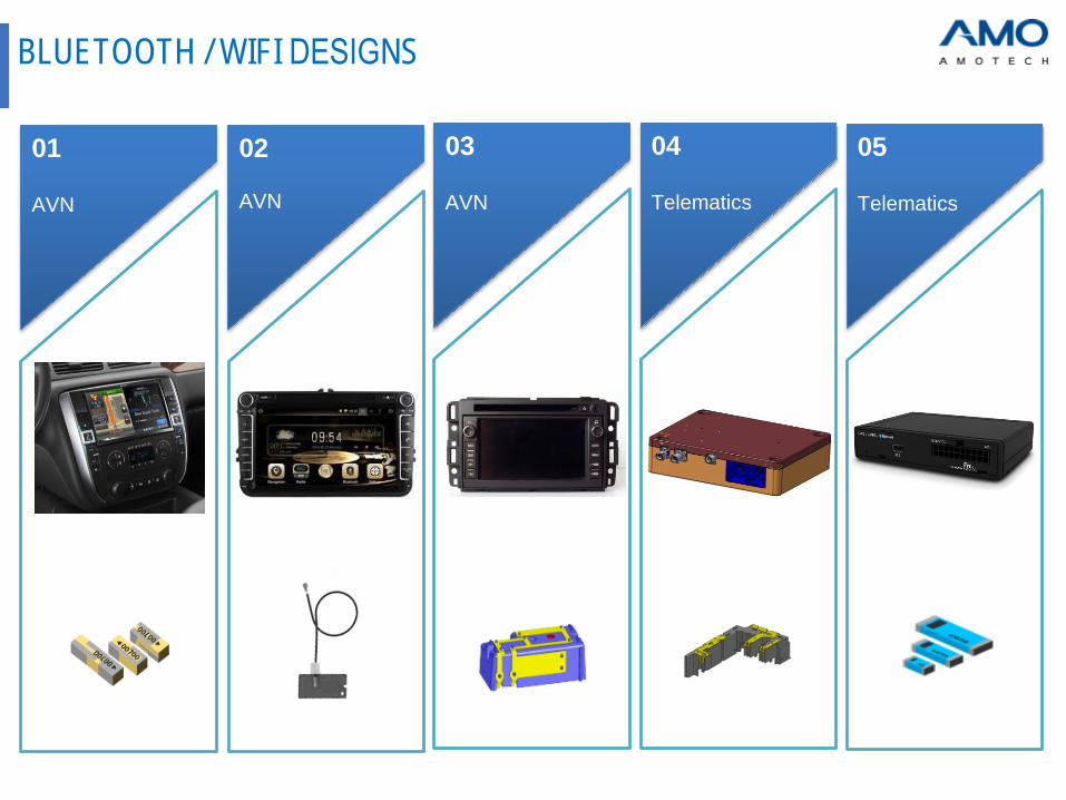
BLUETOOTH / WIFI DESIGNS
02
AVN
03
AVN
01
AVN
04
Telematics
05
Telematics

BLUETOOTH / WIFI NEW ANTENNAS
Frequency Part No. Image Type Bandwidth Radiation pattern
WLAN 5GHz
(5150~5850 MHz)
for IEEE 802.11 a / ac
AMAN103015ST04SMD chip
(10*3*1.5)
Wide
bandwidth
WLAN 5GHz
(5150~5850 MHz)
for IEEE 802.11 a / ac
AMAN103015ST05SMD chip
(10*3*1.5)
Wide
bandwidth
Dual WLAN
(2.4+5GHz)for IEEE 802.11 n
AMAN103015ST07SMD chip
(10*3*1.5)PIFA
GPS
(1575.42 MHz)
+
GNSS
(1592~1610 MHz)
1003015ST03SMD chip
(10*3*1.5)PIFA
▲ @5500MHz
▲ @5500MHz
▲ @2442MHz ▲ @5500MHz
▲ @1575MHz ▲ @1600MHz

BLUETOOTH / WIFI NEW ANTENNAS
Image Details Radiation pattern
Dual-port
external
antenna
√ Port 1: 2.4 GHz
Port 2 : 5 GHz for Access Point (AP)
√ Cable Ø 1.37 mm, length 180 mm
(Cable length changeable)
√ Mini PCI connector
(U.FL Compatible)
WAVE
system
antenna
√ PCB slot antenna with cable
√ Cable : RG178 500mm
(Cable length changeable)
√ V2X wave system
(5850~5925MHz)
▲ @2480MHz
▲ @5500MHz
▲ @5850MHz

BLUETOOTH / WIFI Line-Up
Type Part numberSize
(mm)
Frequency
(MHz)VSWR
Gain (dBi)
Average Peak
Chip
(Helical)
ALA321C3 3.2x1.6x1.2
2400~2485
3.0:1 -1.6 2.3
ALA621C4 6.0x2.0x1.2 2.5:1 -1.0 3.5
ALA621C5 6.0x2.0x1.0 2.5:1 -1.0 3.5
ALA931C5 9.0x3.0x1.2 2.5:1 -0.5 3.5
ALA131C3 11.0x3.0x1.2 2.5:1 -0.5 4.0
Chip
(Mono-Pole)
AMAN402012MS01 4.0x2.0x1.22400~2485
3.0:1 -1.6 2.6
AMAN802012MS02 8.0x2.0x1.2 2.5:1 -0.5 3.5
AMAN1003015ST04 10.0x3.0x1.55150~5850
2.0:1 -1.4 -
AMAN1003015ST05 10.0x3.0x1.5 2.0:1 -1.6 -
Chip
(PIFA)
AMAN201510ST01 2.0x1.5x1.0
2400~2485
3.0:1 -1.0 3.0
AMAN301512ST01 3.0x1.5x1.2 3.0:1 -1.0 3.0
AMAN402012ST01 4.0x2.0x1.2 3.0:1 -1.0 3.0
AMAN1003030ST02 [Dual band] 10.0x3.0x3.02400~2485
5150~58502.5:1 -2.0 -
AMAN1003030ST03 10.0x3.0x3.0 2400~2485 3.0:1 -1.0 3.0
AMAN1003015ST06 [Dual band] 10.0x3.0x1.52400~2485
5150~58502.5:1 -1.2 -
Patch
(On ground)
F12(SMD) 12x12x4 2400~2485 3.0:1 -1.4 3.8
SM25-4552250-STD70 [Dual band] 25x25x52400~2485
5150~58503.0:1
Max.-1.4, -2.7 at edge
Max.-4.2, -1.4 at edge
5.4
6.5

GSM & ISM Line-Up
Type Part Number Size (mm) Frequency VSWRGain (dBi) EVB Size
(mm)Average Peak
PCB + cable
AMMAP007(FPCB) 40.0x15.0x0.55
GSM850
GSM900
DCS1800
PCS1900
WCDMA
UMTS
3:1 -1.0 3.0 -
AMMAP008(PR4) 40.0x15.0x0.14 3:1 -3.0 4.0 -
AMMAP009 40.0x15.0x0.14 3:1 Min. -4.5 - -
Customizing Press or FPCB with carrier Optional - - - -
Main chip
(SMD)
AMMAP003(F) 24.0x5.5x4.4 3.5:1 Min. -3.7 4 114x45
AMMAP005(R) 24.0x5.5x4.4 3.5:1 Min. -3.7 4 114x45
AMMAQ002 22.0x5.5x4.4 3.5:1 Min. -3.3 3 114x45
AMMAP014 35.0x9.0x3.2 2.7:1 Min. -3.3 3 110x50
AMMAL001 35.0x9.0x3.2 US LTE 2.7:1 Min. -2.6 3 120x50
AMMAL002 35.0x9.0x3.2EU LTE
(791~2690MHz)3.0:1 Min. -3.4 3 120x50
AMMAL004 35.0x9.0x3.2 Global LTE 3.8:1 Min. -3.6 3 141X50
Helical type
(Mono-pole)AMAN903012ST05
9.0x3.0x1.2 868MHz 2:1 -7 -3.4 -
9.0x3.0x1.2 915MHz 2:1 -4 -1.3 -

√ Metal sheet
√ High permeability
√ High flux density
√ Specialized in WPC or PMA Rx
√ Ni/Zn, Mn/Zn basis
√ High & low ’
√ Specialized in NFC antenna
√ Specialized in WPC & PMA
√ Specialized in A4WP
AWS AFS AWFS
√ Hybrid type sheet
√ Specialized in WPC+PMA+NFC
High Efficiency
Thin
layers
Multi standard
Heat control
WPC+PMA / WPC+NFCHigh thermal conductivity
Specialized in WPC A1 & PMAHigh efficiency with thin thickness
In-house material
NFC SHIELDING SHEET

NFC
NFC /
NFC tag
▪ Convenient wireless paring
▪ User setting & S/W update available with paring
▪ Dynamic data exchange with mobile having NFC
▪ Information long download with I2C, SPI, UART
▪ Suitable for home appliance application
NFC full
module
▪ Tag & R/W & Peer-to-peer NFC full support (active module)
▪ Payment available
▪ All type of NFC tag support (Type A, B, A/B, F)
▪ Compact size
▪ Suitable for mobile or wearable application
NFC+WLC
combo
▪ Thin thickness but high antenna performance
▪ Having special shielding sheet for NFC and WLC antenna
▪ Payment & Wireless power charging
▪ Suitable for mobile or home appliance application

NFC DESIGNS
02
Key fob
03
Door
01
AVN
04
Car
payment
05
WLC
armrest

AMOTECH
Competitiveness
Quick turn-around for custom design
Value added product with unique materials
Total solution from material to module
Production technology◦ Design own process from development stage
◦ No. 1 in WPT market share
Design & Development◦ Rx / Tx
◦ Circuitry design for module
◦ Combo solutionFollow up market demand
and industrial standard◦ Close cooperation with IC maker
Various materials in house◦ Metal glass sheet
◦ Ferrite sheet◦ Hybrid sheet
NFC+WPC/PMA+MST√ World’s 1st technology√ Total thickness < 0.3 (mm)
WIRELESS POWER CHARGING - WPC

▪ TI / NXP / IDT reference design
▪ ARM, AVR, K-line, LIN, vector can
▪ HFSS simulation
▪ 2D & 3D
▪ NiZn ferrite sheet with flexibility, low loss
and various shape
▪ Available hybrid sheet for NFC & WLC
▪ Having high permeability
Various shielding sheet Simulation
Circuit design & Programming Mechanical design
WPC CAPABILITIES

▲ 2.5 W ▲ 5 W ▲ 10 W ▲ NFC+WLC combo
• Ultra thin profile
• Compatible industrial standard [Inductive / Resonant]
• Working with major IC suppliers
AMO WPT Rx “ Wide Product Line-up”
▲ WPC+PMA
NFC+WPC/PMA+MST√ World’s 1st technology√ Total thickness < 0.3 (mm)
▲ A4WP ▲ PRU category 3
SINGLE MODE
DUAL MODE
MODULE
RESONANT
WPC RX SOLUTIONS

• Customized design available
• Compatible industrial standard [Inductive / Resonant]
AMO WPC Tx
A6
A11
Resonant
Wearable
Medium power (15W)
▲ PTU class 4
WPC TX SOLUTIONS

ESD / EMI SOLUTIONS
ESD/EOS EMI/ESD
AVMC AIES ADF ASF ADMF AHF
Car audioRGB ● ●
I/O ● ●
AVN
LVDS ● ●
SD card ● ●
HDMI ● ●
ClusterRGB ●
RMII (ethernet) ● ●
Telematics RMII (ethernet) ● ●
Multi-jackUSB 2.0 ● ●
Aux ●
RSES
CID
RGB ● ●
LVDS ● ●
Camera
AVM
ADAA
RGB ● ●
LVDS ● ●
BCM CAN ●
▪ EMI / ESD Solution
▪ ESD / Surge solution
CategoryEMI / ESD
filter
EMI
single filter
Series ADF ASF
Size (mm) 1210 / 2012 1608
Category Chip varistorESD
suppressor
Series AVMC AIES
Size (mm)1005 / 1608 /
2012 / 25201015 / 1608
Category CMFDMF
(Dual)
Series AHFE ADMF
Size (mm) 1210 / 2012 1210 / 2012
Compliant with AEC-Q200

AMOVentMemsTM Electric Vent Membrane is “Ultra Thin Fiber” in the form of nonwovens.
AMOventmemsTM creates 3D open pore structure by nm level control of fiber diameter.
• High porosity & Uniform pore size
• Minimal acoustic transmission loss & impedance
1. High air permeability
• Quick recovery after liquid immersion
2. Special treatment
• Flexibility of membrane design upon the customer’s request
• IPX4 / IPX7 / IPX8 / 3 ATM / 5 ATM
3. Customized membrane Waterproof adhesive
Activearea
MEMBRANE

MEMBRANE
Material flexibility
• PVDF, PAN, PES, etc
• PU, Bio-polymers, etc
Process flexibility
• Electric & air combined
hybrid electro spinning
• In-house test available
Production flexibility
• Substitution of existing products
• Pure nano fiber membrane
products
Fiber & Web flexibility
• Fiber diameter : 100 ~ 500nm
• Weight : 0.3 ~ 100gsm
• Thickness : ~ 100㎛• Pore size : 0.1 ~ 10㎛
Fiber web
control
Converting
technology
Spinning
technology
Polymer
science
▶ Vent structure
design technology
▶ Die cutting and assembly
technology
▶ Sound performance test and
analysis
▶ Membrane material
design technology

Your Contact in Europe:
MRC Gigacomp GmbH & Co. KG
Bahnhofstraße 1, 85354 Freising
Tel. +49-8161-9848-0
Fax +49-8161-9848-20
www.mrc-gigacomp.com