solu elementos de maquinas - hamrock, bernard j. jacobson, bo schmid, steven r
DESCRIPTION
solucionario del libro elementos de maquinas de hamrockTRANSCRIPT

Chapter 1 • Introduction
1.1 Design transport containers for milk in 1 gallon and 1 liter sizes.
Notes: There are a number of design considerations that can be included in this problem. Someexamples are considered here, but the student should not be restricted in the types of solutionspursued. This type of problem is an excellent opportunity for brainstorming, where a group isencouraged to provide all possible answers to the problem regardless of feasibility. For example,the materials considered could include wood barrels, ceramic jugs or foil or plastic bags, as inintraveneous fluid containers.
Solution:The transport containers for milk should be easy to handle and store as well as being easy to pourfrom without spilling. The material should be recyclable or be able to be burned leaving harmlesscombustion products. The obvious material choices are paper or plastic materials, although glassbottles and metal cans can be considered as possibilities. For a one liter container the standardtype Pure Pac or Tetra Pac Bric made of plastic carton is a good design.
A one gallon container has to be compact to be easily stored in a refrigerator. The width,depth, and height should be similar in size, which would be about 156 mm x 156 mm x 156 mm.That size is too large to grip with one hand. Therefore, a one gallon container is preferably madeof a plastic with an integral handle.
1.2 Design a simple coat hanger to be used by dry cleaners. It should be able to accommodateboth a winter coat and a pair of trousers. It should function well but also be asinexpensive as possible.
Notes: See the notes to problem 1.
Solution:If they are not hung simultaneously, a steel wire frame of triangular shape with a hook at
the top could be used. The horizontal portion could be covered with a high friction coating or tapeor glue to keep the trousers from sliding off.
For coats, a sturdier frame is needed, requiring either a larger gage of wire or pursuit ofanother alternative such as wood or plastic hangers.
1.3 Journal bearings on train boxcars in the early 19th century used a “stink additive” in theirlubricant. If the bearings got too hot, they would attain a noticeable odor, and an oilerwould give the bearing a squirt of lubricant at the next train stop. What design philosophydoes this illustrate? Explain.
Solution:The most obvious design philosophy is the Doctrine of Manifest Danger. This philosophy
suggests that systems be designed so that a failure can be detected before it occurs. In this case, adry bearing becomes hot, and the bad smell indicates a loss of lubricant before the bearing failureis catastrophic.
It should be noted that other answers are possible. For example, the principal of uniformsafety suggests that the level of safety of all components be kept at the same level. If failure of

one component, in this case a bearing, is imminent, then extra maintenance on this bearing isjustified by the principal of uniform safety.
1.4 A safety chain is used in automotive towing applications. Which design philosophy isbeing incorporated into the towing system design?
Solution:Since the safety chain is used in addition to the towbar, it is an example of redundancy,
and it is a passive system. Furthermore, it is an example of a fail-safe design, because if thetowbar fails, the towed vehicle will follow the car and will not swerve into other lanes and collidewith other vehicles.
1.5 A hand-held drilling machine has a bearing to take up radial and thrust load from thedrill. Depending on the number of hours the drill is expected to be used before it isscrapped, different bearing arrangements will be chosen. A rubber bushing has a 50-hrlife. A small ball bearing has a 300-hr life. A two bearing combination of a ball bearingand a cylindrical roller bearing has a 10,000 hr life. The cost ratios for the bearingarrangements are 1:5:20. What is the optimum bearing type for a simple drill, asemiprofessional drill, and a professional drill?
Notes: This problem is fairly subjective, but there should be a realization that there is an increasein expected life for a professional drill versus a simple drill. In fact, for certain users, a 50 hourlife is probably sufficient.
Solution:Notice that the cost per time is highest for the rubber bushing and lowest for the ball bearingcylindrical bearing combination. However, the absolute cost is higher for the longer lastingcomponents, so the expected life must be assessed. Rough estimates based on expected lives areas follows.a) Simple drill - use rubber bushingbearings.b) Semi-professional drill - either two ball bearings or a ball and cylindrical roller bearingcombination.c) Professional drill - use a ball and cylindrical roller bearing combination.
1.6 Using the hand-held drill described in Problem 1.5, if the solution with the small ballbearing was chosen for a semiprofessional drill, the bearing life could be estimated to be300 hr until the first spall forms in a race. The time from first spall to when the wholerolling-contact surface is covered with spalls is 200hr, and the time from then until a ballcracks is 100 hr. What is the bearing lifea) If high precision is required?b) If vibrations are irrelevent?c) If an accident can happen when a ball breaks?
Notes: This problem is fairly subjective, but there should be a realization that there is a decreasein expected life for the high precision drill, etc.
Solution:a) For high precision, no spall should be allowed so the life is 300 hrs.b) If vibrations are irrelevent, the drill can be used until a ball breaks, or 600hours.

c) Depending on the severity of the accident, it is possible that an entirely different bearingshould be used. However, safety allowances of 300-500 hours may be reasonable.
1.7 The dimensions of skis used for downhill competition need to be determined. Themaximum force transmitted from one foot to the ski is 2500N, but the snow conditionsare not known in advance, so the bending moment acting on the skis is not known. Theweight of the skier and equipment is 100 kg. Estimate the safety factor needed.
Notes: There are two different approaches, that of section 1.5.1.1, and that of a worst casescenario.
Solution:Using the approach of section 1.5.1.1, the largest safety factor from Table 1.1 is nsx=3.95,
and the largest value of nsy from Table 1.2 is 1.6. Therefore, the largest safety factor, if there ispoor control of materials and loading, and if the consequences are sever, is given by Equation 1.2as:
ns=nsxnsy=(3.95)(1.6)=6.32Another approach is to perform a worst case scenario analysis. If the weight of skier and
equipment is 100 kg and the maximum load on the ski is 2500N, then the centrigugal accelerationis 23 m/s2. If the speed of the skier is 35m/s (126km/hr), the radius from the ski track will be 53m. If the speed is 20 m/s, the radius is 17.4m. This means that no overstressing should ever occurdue to bending of the ski, so the safety factor could be chosen just above one.
1.8 A crane has a loading hook that is hanging on a steel wire. The allowable normal tensilestress in the wire gives an allowable force of 100,000N. Find the safety factor that shouldbe used.a) If the wire material is not controlled, the load can cause impact, and fastening the hookin the wire causes stress concentrations. (If the wire breaks, people can be seriously hurtand expensive equipment can be destroyed.)b) If the wire material is extremely well controlled, no impact loads are applied, and thehook is fastened in the wire without stress concentrations. (If the wire breaks, no peopleor expensive equipment can be damaged.)
Notes: Equation (1.2) is needed to solve this problem, with data obtained from Tables 1.1 and 1.2.
Solution:a). If the quality of materials is poor (A=p), the control over the load to the part is poor (B=p), andthe accuracy of the stress analysis is poor (C=p), then nsx=3.95 as given in Table 1.1. If theeconomic impact and danger are both very serious (D=E=vs), then from Table 1.2, nsy=1.6.Therefore, the required safety factor is obtained from Equation (1.2) as
ns=nsxnsy=(3.95)(1.6)=6.3b) If the quality of materials, the control over the load to the part, and the accuracy of the stressanalysis are all very good (A=B=C=vg), then nsx=1.1 as given in Table 1.1. If the economicimpact and danger are both not serious (D=E=ns), then from Table 1.2, nsy=1.0. Therefore, therequired safety factor is obtained from Equation (1.2) as
ns=nsxnsy=(1.1)(1.0)=1.1

1.9 Give three examples of fail-safe and fail-unsafe products.
Notes: This is an open-ended problem, and many different solutions are possible.
Solution:Examples of fail safe products are: 1) electric motors, which fail to move and cause no hazardswhen they fail. 2) Bowling pins, because of their distance from bowlers, do not present anyhazards when they shatter. 3) Furniture upholstery, which causes aesthetic objection long beforestructural failure occurs. Examples of fail unsafe products include: 1) Bungee cords, as in bungeecord jumping from bridges and the like; 2) parachutes, which cause a fatal injury in the vastmajority of failures, and 3) A fan on an exhaust hood over a fume producing tank, such as anelectroplating tank. Failure of the forced air circulation system exposes plant personnel to harmfulfumes.
1.10 An acid container will damage the environment and the people around if it leaks. Thecost of the container is proportional to the container wall thickness. The safety can beincreased either by making the container wall thicker or by mounting a reserve tray underthe container to collect the leaking acid. The reserve tray costs 10% of the thick-walledcontainer cost. Which is less costly, to increase the wall thickness or to mount a reservetray under the container?
Notes: This problem uses the approach described by Equation (1.2) and Tables 1.1 and 1.2.
Solution:If the safety factor is unchanged, then for a thicker container wall, we see that with danger topersonnel rated very serious and economic impact very serious (D=E=vs), then nsy=1.6. If areserve tray is used, the required safety factor for the container (D=E=ns) is nsy=1.0. Therefore, ifA is the cost of the container with thicker walls, then the cost of the container with a reserve trayis
A1.6
+ 0.1( )A = 0.725A
Therefore, with the same safety factor, it is less costly to have the reserve tray.
1.11 The unit for dynamic viscosity in the SI system is newton-seconds per square meter, or
pascal-seconds (N-s/m2 = Pa-s). How can that unit be rewritten by using the basic
relationships described by Newton’s law for force and acceleration?
Notes: The only units needed are kg, m, and s.
Solution:By definition, a Newton is a kilogram-meter per square second. Therefore, the unit for dynamicviscosity can be written as:
Ns
m2 = kgm
s2
s
m2 = kgsm

1.12 The unit for dynamic viscosity in Problem 1.11 is newton-second per square meter
(Ns/m2) and the kinematic viscosity is defined as the viscosity divided by the fluid
density. Find at least one unit for kinematic viscosity.
Notes: The only units needed are m and s.
Solution:The units for kinematic viscosity can be written as:
ηk = ηρ
=
Ns
m2
kg
m3
= Nsmkg
=
kgm
s2
sm
kg= m2
s
1.13 A square surface has sides 1m long. The sides can be split into decimeters, centimeters,or millimeters, where 1m=10dm, 1dm=10cm, and 1cm=10mm. How many millimeters,centimeters, and decimeters equal 1m? Also, how many square millimeters, squarecentimeters and square decimeters equal one square meter?
Notes: This is fairly straightforward; Table 1.3(b) is useful.
Solution:From Table 1.3(b), one meter equals 10 dm, 100 cm and 1000 mm. Therefore, a square meter is:
1m2=(1000mm)
2=1 million (mm)
2.
1m2=(100cm)
2=10,000 (cm)
2
1m2=(10dm)
2=100(dm)
2
1.14 A volume is 1 tera (mm3) large. Calculate how long the sides of a cube must be to contain
that volume.
Notes: From Table 1.3 (b), tera is 1 x 10¹²
.
Solution:A tera (mm
3) is 10
12 (mm
3). Therefore, this volume is
1012 mm3 1m1000mm
3
= 1000m3
A cube with this volume has sides with length of 10m.
1.15 A ray of light travels at a speed of 300,000 km/s=3 x 108m/s. How fast will it travel in 1
ps, 1 ns, and 1µs?
Notes: An interesting assignment is to have students submit string of the required length for thepicosecond and nanosecond cases.
Solution:The distance traveled in a picosecond is:

x = v∆t = 3 ×10⁸m / s( ) 10−12s( ) = 3 ×10⁻⁴m = 0.3mm
In one nanosecond, light travels:
x = v∆t = 3 ×10⁸m / s( ) 10−9s( ) = 0.3 m = 300mm
In one microsecond, light travels:
x = v∆t = 3 ×10⁸m / s( ) 10−6s( ) = 300m
1.16 Two smooth flat surfaces are separated by a 10-µm thick lubricant film. The viscosity of
the lubricant is 0.100 Pa-s. One surface has an area of 1 dm2 and slides over the plane
surface with a velocity of 1 km/hr. Determine the friction force due to shearing of thelubricant film. Assume the friction force is the viscosity times the surface area timesvelocity of the moving surfaces and divided by the lubricant film thickness.
Notes This problem is simple if consistent units are used.
Solution:Rewriting terms into consistent units, 10µm=10
-5m, 0.100Pas=0.100Ns/m
2,
1dm2=(0.1m)
2=0.01m
2, and
1kmhr
= 1000m3600s
= 0.2778m / s
Therefore the friction force is given by:
F = η0Aub
h=
0.1Ns
m2
0.001m2( ) 0.2778m / s( )
10−5m= 27.78N
1.17 A firefighter sprays water on a house. The nozzle diameter is small relative to the hosediameter, so the force on the nozzle from the water is
F = vdma
dtwhere v is the water velocity, and dma/dt is the water mass flow per unit time. Calculatethe force the firefighter needs to hold the nozzle if the water mass flow rate is 3 tons/hrand the water velocity is 100km/hr.
Notes: A ton can be misperceived; in metric units, a ton is 1000kg, while in English units it is2000 lbf. Since the units in this problem are metric, the metric interpretation is used. Thisproblem is not difficult as long as consistent units are used.
Solution:The velocity can be written as:
100kmhr
= 100,000m3600s
= 27.78m / s
The mass flow rate can be rewritten as:dma
dt= 3tons
hr= 3000kg
3600s= 0.8333kg / s
Therefore, the force needed is

F = vdma
dt= 27.78m / s( ) 0.8333kg / s( ) = 23.15 N
1.18 The mass of a car is 1346 kg. The four passengers in the car weigh 65.55 kg, 75.23 kg,88.66kg, and 91.32 kg. It is raining and the additional weight due to the water on the caris 1.349 kg. Calculate the total weight of the car, including the weight of the passengersand the weight of the water, using four significant figures.
Solution:The weight is
Wtot=1346kg+65.55kg+75.23kg+88.66kg+91.32kg+1.349kg±0.5kg=1668.109kg±0.5kgTherefore the total weight is 1668kg.
1.19 During an acceleration test of a car, the acceleration was measured to be 1.4363 m/s2.Because slush and mud adhered to the bottom of the car, the weight was estimated to be1400±100kg. Calculate the force driving the car and indicate the accuracy.
Solution:Since the force is given by P=maa, the force is given by
P = maa = 1400kg ±100kg( ) 1.4363m / s2( ) = 2010.82 ±143.6 N =2154.45N
1867.19N

Page 2-1
Chapter 2 • Load, Stress and Strain
2.1 The stepped shaft A-B-C shown in sketch a is loaded with the forces P1 and/or P2. Notethat P1 gives a tensile stress σ in B-C and σ/4 in A-B and that P2 gives a bending stress σat B and 1.5σ at A. What is the critical sectiona) If only P1 is applied?b) If only P2 is applied?c) If both P1 and P2 are applied?
Notes: This solution will ignore advanced concepts such as stress concentrations that would existat the fillet, since this material is covered later in the text. Similarly, the location in the crosssection where the maximum stress occurs could be identified with the information in Chapter 4,but will be left for the student.
Solution:If only P1 is applied, the critical section is the length B-C, since the tensile stress is highest in thissection.If only P2 is applied, the largest stress occurs at A.If both P1 and P2 are applied, the maximum stress in section A-B occurs at point A and is
σA=σ/4+1.5σ=1.75σThe maximum stress in section B-C occurs at point B and is
σB=σ+σ=2σTherefore, the critical section is B-C, in particular point B.
2.2 The stepped shaft in Problem 2.1 (sketch a) has loads P1 and P2. Find the loadclassification if P1’s variation is sinuous and P2 is the load from a weighta) If only P1 is applied.b) If only P2 is applied.c) If both P1 and P2 are applied.
Notes: This solution uses the terminology on pages 30-32.
Solution:If only P1 is applied, then the load is cyclic with respect to time (see page 30), and is a
normal load (see page 31).If only P2 is applied, the load is sustained with respect to time, and is both a shear load
and a bending load. However, for long columns, bending is usually more important than shear, soit is reasonable to classify P2 as a bending load.
If both P1 and P2 are applied, then the load is cyclic with respect to time (although themean stress is not zero), and the loading is combined (see page 32).
2.3 The sign convention for bending moments can be derived from the differential equationfor the elastic line:
Page 2-2
EIy”=-MWhere
E=modulus of elasticity, PaI=area moment of inertia, m4
M=bending moment, N-my"=d2y/dx2=second derivative of y with respect to x, m-1
y=deflection, mThis gives a positive (tensile) stress in the fibers on the beam in the positive (y) direction.Find how the slope of the beam changes with increasing x coordinate for positive andnegative bending.
Notes: The slope of the beam is the first derivative of the deflection, so one must integrate thegiven equation to obtain the solution.
Solution:The slope of the beam is given by θ=dy/dx. Integrating the given equation,
dy
dx= θ = −
Mx
EI+ C
Where C is a constant of integration, and reflects the effects of boundary conditions. If we ignoreC, we can see that if the bending moment is negative, the slope of the beam is positive forpositive x and negative for negative x. If the moment is positive, the slope is negative for positivex and positive for negative x.
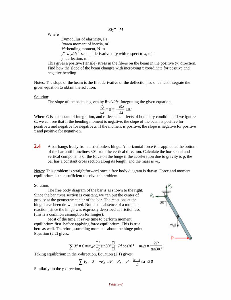
2.4 A bar hangs freely from a frictionless hinge. A horizontal force P is applied at the bottomof the bar until it inclines 30° from the vertical direction. Calculate the horizontal andvertical components of the force on the hinge if the acceleration due to gravity is g, thebar has a constant cross section along its length, and the mass is ma.
Notes: This problem is straightforward once a free body diagram is drawn. Force and momentequilibrium is then sufficient to solve the problem.
Solution:The free body diagram of the bar is as shown to the right.
Since the bar cross section is constant, we can put the center ofgravity at the geometric center of the bar. The reactions at thehinge have been drawn in red. Notice the absence of a momentreaction, since the hinge was expressly described as frictionless(this is a common assumption for hinges).
Most of the time, it saves time to perform momentequilibrium first, before applying force equilibrium. This is truehere as well. Therefore, summing moments about the hinge point,Equation (2.2) gives:
M = 0∑ = magl
2sin30°
− Pl cos30°; mag =
2P
tan30°Taking equilibrium in the x-direction, Equation (2.1) gives:
Px = 0 = −Rx + P; Rx = P∑ =gma
2t a n 3 0°
Similarly, in the y-direction,

Page 2-3
Py = 0 = Ry − gma ; Ry = gma∑
2.5 Sketch b shows the forces acting on a rectangle. Is the rectangle in equilibrium?
Notes: To satisfy equilibrium, Equations (2.3) must be satisfied.
Solution:Taking the sum of forces in the x-direction,
ΣFx=30N-20N-10N=0Therefore, equilibrium in the x-direction is satisfied. Taking equilibrium in the y-direction gives
ΣFy=-18N+20N-20N+18N=0Therefore, equilibrium in the y-direction is satisfied. Taking moments about point A,
ΣMA=(20N)(7cm)+(10N)(5cm)-18N(7cm)=64NcmTherefore, moment equilibrium is not satisfied, and the rectangle is not in equilibrium.
2.6 Sketch c shows the forces acting on a triangle. Is the triangle in equilibrium?
Notes: To satisfy equilibrium, Equations (2.3) must be satisfied.
Solution:Taking the sum of forces in the x-direction,
ΣFx=65.37N-40N(cos10°)-30N(cos30°)=0.00Therefore, equilibrium in the x-direction is satisfied. Taking equilibrium in the y-direction gives
ΣFy=39.76N-17.81N-40N(sin10°)-30N(sin30°)=0.00Therefore, equilibrium in the y-direction is satisfied. Taking moments about point A,
ΣMA=(39.76N)(2.5cm)-40N(cos10°)(5cm)+30N(sin30°)(6.5cm)=0.00NcmTherefore, the triangle is in equilibrium.

Page 2-4
2.7 Sketch d shows a cube with side lengths a and eight forces acting at the corners. Is thecube in equilibrium?
Notes: For three dimensional equilibrium, Equations (2.1) and (2.2) must be satisfied.
Solution:Taking the sum of forces in the x-direction,
ΣFx=P+P-P-P=0Therefore, equilibrium in the x-direction is satisfied. Taking equilibrium in the y-direction gives
ΣFy=P+P-P-P=0Therefore, equilibrium in the y-direction is satisfied. There are no forces in the z-direction, soequilibrium is automatically satisfied. Taking moments about the z-axis,
ΣMoz=Pa+Pa-Pa-Pa=0Therefore, equilibrium about the z-axis is satisfied. Taking moments about the x-axis,
ΣMoz=Pa-Pa=0Therefore, equilibrium about the x-axis is satisfied. Taking moments about the y-axis,
ΣMoy=Pa-Pa=0Therefore, the cube is in equilibrium.
2.8 A downhill skier stands on a slope with a 5° inclination. The coefficient of frictionbetween the skis and the snow is 0.10 when the ski is stationary and 0.07 when the skistarts to slide. Is the skier in static equilibrium when he is stationary and when he slidesdown the slope?
Notes: For equilibrium, the force Equations in (2.3) needs to be satisfied.

Page 2-5
Solution:A free-body diagram of the skier is shown tothe right. The skier’s weight is mag, and theslope has a normal force as a reaction and afriction force which develops tangent to theslope. Summing forces in the direction normalto the slope yields:
ΣF=N-magcos5°; N=magcos5°Taking forces tangent to the slope,
ΣF=magsin5°-µN=magsin5°-µmagcos5°; µ=tan5°=0.08749If the skier is stationary, the coefficient of friction is 0.10, and there is enough friction to keep theskier stationary. If the skier is moving, then the coefficient of friction is 0.07, so the friction forcedeveloped is not enough to maintain equilibrium. The skier will accelerate.
2.9 Given the components shown in sketches e and f, draw the free-body diagram of eachcomponent and calculate the forces.
Notes: For equilibrium, the force Equations in (2.3) needs to be satisfied. Assume there is nofriction in sketch (e). In sketch f, moment equilibrium shows that the only possible force in eachmember is an axial force.
Solution:The free body diagram for sketch e is shown to the left. Flat surfaces give normal reaction forcesas shown. From Equation (2.3), and summing forces in the y-direction,
ΣFy=0=-W+N1cos30°+N2cos60°; N1=W/cos30°-N2(cos60°/cos30°)Summing forces in the x-direction,
ΣFx=0=N1sin30°-N2sin60°=(W/cos30°-N2(cos60°/cos30°))sin30°-N2sin60°; N2=0.5WSubstituting into the x-direction equilibrium equation gives N1=0.866W.The free body diagram for sketch f is shown to the right. For equilibrium in the x-direction,
ΣFx=0=P-P2sin30°; P2=2P=2.4kNTaking equilibrium in the y-direciton.
ΣFy=-P1+P2cos30°=-P1+2Pcos30°; P1=1.732P=2.08kN

Page 2-6
2.10 A 5-m-long bar is loaded as shown in sketch g. The bar cross section is constant along itslength. Draw the shear and moment diagrams and locate the critical section.
Notes: In such problems, one must first obtain the reactions before generating the shear andmoment diagrams. Also, it is useful to consider moment equilibrium first. In this problem, theshear and moment diagrams are obtained through the method of sections.
Solution:The reaction forces have been added to the figure in red. Summing moments about the origingives
ΣMo=0=10kN(2m)-Ay(3m)+3.2kN(5m);Ay=12kNSumming forces in the y-direction yields
ΣFy=0=-Oy+10kN-Ay+3.2kN; Oy=10kN-12kN+3.2kN=1.2kNThe method of sections described on page 39 is used to obtain the shear and moment diagrams.This proceeds as follows:a) 0≤x<2m: ΣFy=0=-Oy+V; V=Oy=1.2kN
ΣMO=0=M-V(x); M=Vx=(1.2kN)xNote: at x=2m, M=2.4kNm
b) 2m≤x<3m: ΣFy=0=-Oy+10kN+V;V=Oy-10kN=-8.8kN
ΣMO=0=M-V(x)-10kN(2m); M=20kNm-(8.8kN)x
c)3m≤x: ΣFy=0=-Oy+10kN-12kN+V;V=3.2kN
ΣMO=0=M-V(x)-10kN(2m)+12kN(3m);M=-16kNm+3.2x
The shear and moment diagrams are plotted as follows:
From these shear and moment diagrams, it can be seen that the critical section is at point A.
2.11 A beam is supported by a wire in one end and by a pin in the other end. The beam isloaded by a force parallel with the wire. What is the direction of the reaction force in thepin?
Notes: This merely requires an understanding of the equations of equilibrium. One of thefundamental notions is that “you can’t push on a rope”, so that the wire can only support an axial,tensile load.

Page 2-7
Solution:Force equilibrium gives that the force in the pin has to be parallel with the wire since the wire canonly transmit an axial force. Therefore, the force in the pin has to be in the same direction as inthe wire.
2.12 Sketch h shows a simple bridge. The midpoint of the bridge is held up by a wire leadingto the top hinge of the two equal beams. When a truck runs over the bridge, the force inthe wire is measured to be 500,000 N. Determine the forces in the beams and thehorizontal force component in the middle of the bridge.
Notes: This problem can be easily solved by drawing a free body diagram of one of the beamsand then applying the equations of equilibrium.
Solution:A free body diagram of the left beam is shown to the right. It is assumed that each beam takesone-half the load, as shown. From moment equilibrium, about the pin, it can be seen that
ΣM=0=(250,000N)(lcos45°)-PH(lsin45°); PH=250,000NTherefore, the load carried by the beam is
Pbeam = 250kN( )2 + 250kN( )2 = 353.6kNTaking force equilibrium in the horizontal direction gives
ΣFh=0=Rx-PH; Rx=PH=250kNThis is the horizontal force component in the middle of the bridge.
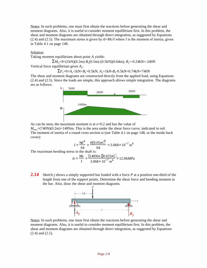
2.13 Sketch i shows a 0.05-m-diameter steel shaft supported by self-aligning bearings (whichcan provide radial but not bending loads on the shaft). A gear causes each force to beapplied as shown. All length dimensions are in meters. The shaft can be consideredweightless. Determine the forces at A and B and the maximum bending stress. Drawshear and moment diagrams.
Page 2-8
Notes: In such problems, one must first obtain the reactions before generating the shear andmoment diagrams. Also, it is useful to consider moment equilibrium first. In this problem, theshear and moment diagrams are obtained through direct integration, as suggested by Equations(2.4) and (2.5). The maximum stress is given by σ=Mc/I where I is the moment of inertia, givenin Table 4.1 on page 148.
Solution:Taking moment equilibrium about point A yields:
ΣMA=0=(1kN)(0.2m)-By(0.5m)-(0.5kN)(0.64m); By=-0.24kN=-240NVertical force equilibrium gives Ay:
ΣFy=0=Ay-1kN+By+0.5kN; Ay=1kN-By-0.5kN=0.74kN=740NThe shear and moment diagrams are constructed directly from the applied load, using Equations(2.4) and (2.5). Since the loads are simple, this approach allows simple integration. The diagramsare as follows:
As can be seen, the maximum moment is at x=0.2 and has the value ofMmax=(740N)(0.2m)=148Nm. This is the area under the shear force curve, indicated in red.The moment of inertia of a round cross section is (see Table 4.1 on page 148, or the inside backcover):
I = πd4
64= π 0.05m( )4
64= 3.068× 10⁻⁷ m4
The maximum bending stress in the shaft is:
σ = McI
= 148Nm( ) 0.025m( )3.068× 10⁻⁷ m4 = 12.06MPa
2.14 Sketch j shows a simply supported bar loaded with a force P at a position one-third of thelength from one of the support points. Determine the shear force and bending moment inthe bar. Also, draw the shear and moment diagrams.
Notes: In such problems, one must first obtain the reactions before generating the shear andmoment diagrams. Also, it is useful to consider moment equilibrium first. In this problem, theshear and moment diagrams are obtained through direct integration, as suggested by Equations(2.4) and (2.5).

Page 2-9
Solution:Moment equilibrium about point A yields:
ΣMA=0=P(l/3)-By(l); By=P/3Vertical force equilibrium gives:
ΣFy=0=Ay-P+By; Ay=P-By=P-P/3=2P/3The shear and moment diagrams are obtained through direct integration and are shown below.
2.15 Sketch k shows a simply supported bar loaded by two equally large forces P at a distancel/4 from its ends. Determine the shear force and bending moment in the bar, and find thecritical section with the largest bending moment. Also, draw the shear and momentdiagrams.
Notes: In such problems, one must first obtain the reactions before generating the shear andmoment diagrams. Also, it is useful to consider moment equilibrium first. In this problem, theshear and moment diagrams are obtained through direct integration, as suggested by Equations(2.4) and (2.5).
Solution:Moment equilibrium about point A yields:
ΣMA=0=P(l/4)+P(3l/4)-By(l); By=PVertical force equilibrium gives
ΣFy=0=Ay-P-P+By; Ay=PThe shear and moment diagrams are obtained through direct integration and are shown below.
The largest bending moment occurs between the two applied forces and has the magnitude ofM=Pl/4.
2.16 The bar shown in sketch l is loaded by the force P. Determine the shear force andbending moment in the bar. Also, draw the shear and moment diagrams.

Page 2-10
Notes: In such problems, one must first obtain the reactions before generating the shear andmoment diagrams. Also, it is useful to consider moment equilibrium first. In this problem, theshear and moment diagrams are obtained through direct integration, as suggested by Equations(2.4) and (2.5).
Solution:Moment equilibrium about point A yields:
ΣMA=0=Pl+Byl; By=-PVertical force equilibrium gives:
ΣFy=0=-P+Ay+By; Ay=2PThe shear and moment diagrams are obtained through direct integration and are shown below.
2.17 Sketch m shows a simply supported bar with a constant load per unit length w0 imposedover its entire length. Determine the shear force and bending moment as functions of x.Draw a graph of these functions. Also, find the critical section with the largest bendingmoment.
Notes: In such problems, one must first obtain the reactions before generating the shear andmoment diagrams. Also, it is useful to consider moment equilibrium first. In this problem, theshear and moment diagrams are obtained through direct integration, as suggested by Equations(2.4) and (2.5).
Solution:For the purposes of equilibrium, the distributed load can be replaced by a point load of magnitudew0l at the midpoint of the span. Therefore, moment equilibrium about point A yields:
MA = 0 = w0ll2
− Byl∑ ; By = w0 l
2Force equilibrium in the vertical direction gives:
Fy = 0 = Ay − w0l∑ +By ; Ay = w0 l2
The shear and moment diagrams are obtained through direct integration and are shown below.

Page 2-11
It can be seen that the maximum moment occurs at mid-span. The magnitude of this force is thearea under either triangle on the shear curve, as suggested by Equation (2.5). This gives
Mmax = 12
wol2
l
2
= w0l
2
8
2.18 Sketch n shows a simply supported beam loaded with a ramp function over its entirelength, the largest value being 2P/l. Determine the shear force and the bending momentand the critical section with the largest bending moment. Also, draw the shear andmoment diagrams.
Notes: One must first obtain the reactions before generating the shear and moment diagrams.Also, it is useful to consider moment equilibrium first. In this problem, the shear and momentdiagrams are obtained through the method of sections.
Solution:The loading is described by
q x( ) = − 2Pl
xl
= − 2Px
l2
In analyzing equilibrium, the loading is replaced by a force of magnitude P at a location ofx=2l/3. Therefore, moment equilibrium about point A gives:
MA = 0 = P2 l3
− By l( ); By = 2P
3∑
Vertical force equilibrium gives:
Fy = 0 = Ay − P + By ; Ay = P − By = P3
∑Taking a section at a location x in the span,
Fy = 0 = Ay − 12
2Px
l2
x( )∑ −V ; V = P
3− Px2
l2
MA = 0 = 12
2Px
l2
x( ) 2
3x
∑ + Vx − M;
M = 2Px3
3l2 +P
3− Px2
l2
x = Px
3− Px3
3l2
The shear and moment diagrams are shown below:

Page 2-12
The maximum moment occurs when V=0, which occurs at:
0 = P3
− Px2
l2 ; x = l3
Substituting this into the moment equation gives
Mmax = P3
l3
−
P
3l2l3
3
= Pl3 3
− Pl9 3
= 2Pl9 3
2.19 Draw the shear and moment diagrams, and determine the critical section for the loadingconditions shown in sketch o. Neglect the weight of the bar. Let w0=100kN/m, P=5kN,M=2x10
4N-m, and l=300mm.
Notes: One must first obtain the reactions before generating the shear and moment diagrams.Also, it is useful to consider moment equilibrium first. In this problem, the shear and momentdiagrams are obtained through singularity functions. Table 2.2 on page 43 is useful for writingthe load distribution in terms of singularity functions.
Solution:For equilibrium reasons, the distributed loads can be replaced by point loads as shown below:
Taking moment equilibrium about point A gives:
MA = 0 = 5kN( ) 0.200m3
+10kN 0.15m( )+ 5kN 0.233 m( ) − By 0.2m( )+ 5kN 0.3m( ) + 20kNm∑
or By=22.6kN. Taking force equilibrium in the vertical direction gives:Fy = 0 = Ay − 5kN −10kN − 5kN + By − 5kN ;Ay = −2.4kN∑
Therefore, the load distribution can be written in terms of singularity functions as (see Table 2.2on page 43):
−q x( ) = 2.4kN x −1 − 1kN / m x 1 − x − 0.1 m 1[ ] + 22.6 kN x − 0.2 m −1
+1kN / m x − 0.2m 1 − x − 0.3 m 1[ ]− 5kN x −0.3m −1 + 20kNm x − 0.3m −2
Therefore, the shear distribution is given by Equation (2.4) as
V x( )= 2.4kN x 0 − 1kN / m
2x 2 − x − 0.1m 2 − x − 0.2m 2 + x − 0.3m 2[ ]
+22.6kN x − 0.2m 0 − 5kN x − 0.3m 0 + 20kNm x − 0.3m −1
And the moment distribution is given by Equation (2.5) as

Page 2-13
M x( ) = 2.4 kN x 1 − 1kN / m
6x 3 − x − 0.1 m 3 − x − 0.2 m 3 + x − 0.3m 3[ ]
+22.6kN x − 0.2 m 1 − 5kN x − 0.3m 1 + 20kNm x − 0.3m 0
The shear and moment diagrams are sketched below:
2.20 Redo problem 2.19 while considering the weight of the bar per unit length to bew0=5N/m.
Notes: This problem is useful after Problem 2.19 has been completed, since the statics thensuggests the answer - that the beam weight is negligible.
Solution:Taking moment equilibrium about point A gives:
MA = 0 = 5kN( ) 0.200m
3
− 5N / m( ) 0.3m( ) 0.15m( )∑
+10kN 0.15m( ) + 5kN 0.233m( ) − By 0.2m( ) + 5kN 0.3m( ) + 20kNm
or By=22.601kN. Taking force equilibrium in the vertical direction gives:Fy = 0 = Ay − 5kN −10kN − 5kN + By − 5kN ;Ay = −2.4004kN∑
These reactions are so close to the reactions in Problem 2.19 that the difference in the shear andmoment diagrams is negligible. The derivation is identical to Problem 2.19, but the load functionhas two terms associated with the weight.
2.21 Find the expressions for the shear force, bendingmoment, and axial load P for the curved member shownin sketch p. Neglect the weight of the bar. Let P=10Nand r=1m.
Notes: The reactions must be determined before the problem canbe solved. The method of sections can be used to obtain asolution for this problem.
Solution:Taking moments about the base of the curved member gives:
ΣM=0=M0-(Pcos30°)r-(Psin30°)r; M0=1.366Pr=13.7NmTaking vertical force equilibrium:
ΣFy=0=Ry-Psin30°; Ry=Psin30°=5NTaking horizontal force equilibrium,
ΣFx=0=Rx+Pcos30°; Rx=-8.66NTaking a section of the member at an angle θ gives the free body diagram shown below.Equilibrium in the x-direction gives:

Page 2-14
ΣFx=0=Rx+Vcosθ-PsinθEquilibrium in the y-direction gives:
ΣFy=0=Ry-Vsinθ-PcosθThese two equations yield
P=Rxsinθ+Rycosθ=(-8.66N)sinθ+(5N)cosθV=-Rxcosθ+Rysinθ=(8.66N)cosθ+(5N)sinθ
Moment equilibrium about the curved member end gives:ΣM=0=M0+Rx(rsinθ)-Ry(r-rcosθ)+M; M=-M0-rRxsinθ+rRy(1-cosθ)
M=-13.7Nm-(1m)(-8.66N)sinθ+(1m)(5N)(1-cosθ)=-13.7Nm+8.66Nmsinθ+5Nm(1-cosθ)
2.22 Sketch q shows a sinusoidal distributed force applied to a beam. Determine the shearforce and bending moment for each section of the beam.
Notes: The reactions must be determined before the problem can be solved. This solution usessingularity functions to obtain the shear and bending moment diagrams.
Solution:The sinusoidal distribution is symmetric, so we know that the statically equivalent load can beplaced at the center of the beam, and has a magnitude of
P = w0 sinπxl
dx0
l∫ = − lw0
πcos
πxl
x=0
x= l
= 2 lw0
πTaking moment equilibrium about point A,
MA = 0 = Pl2
− By l( ); By = P
2= lw0
π∑Vertical force equilibrium gives
Fy = Ay − P + By ;Ay = P − By = 2lw0
π−∑ lw0
π= lw0
πThe load function is given by
−q x( )= − lw0
πx −1 + w0 sin
πxl
− lw0
πx − l −1
Equation (2.4) gives
V x( )= − q x( )dx∫ = − lw0
πx 0 − lw0
πcos
πxl
+ lw0
π− lw0
πx − l 0
Equation (2.5) gives
M x( ) = V x( )dx∫ = − lw0
πx 1 − l2 w0
π2 sinπxl
+ lw0x
π− lw0
πx − l 1
2.23 Find the length c that gives the smallest maximum bending moment for the loaddistribution shown in sketch r.

Page 2-15
Notes: The reactions must be determined before the problem can be solved. This solution usesmethod of sections to obtain the shear and bending moment diagrams. Note that large negativebending stresses are still objectionable. For small values of c, note that the moment in the centerpart will be large; for large values of c, the moment towards the edges will be larger. Therefore,the solution requires that the absolute value of the largest negative moment equal the largestpositive moment.
Solution:Because of symmetry, both R1 and R2 will have the value of w0l/4. Note that the shear andbending moment diagrams will be symmetric. Therefore, using the method of sections between cand l/2, and considering only moment equilibrium,
Mx = 0 =w0x2
2 l
x
3
−
w0l
4x − c( ) + M; M =
w0l
4x − c( ) −∑ w0 x3
6 lAt x=c, this gives a value of
Mx=c =w0l
4c − c( ) −
w0c3
6l= −
w0c3
6lwhile at x=l/2,
Mx= l / 2 =w0 l
4
l
2− c
−
w0l
2
3
6l=
w0l2
8−
w0lc
4−
w0l2
48=
5w0 l2
48−
w0lc
4Using the requirement that Mx=l/2=-Mx=c gives:
w0c3
6l=
5w0 l2
48−
w0lc
4;
c3
6l=
5l2
48−
lc
4This is solved numerically as c=0.380l.
2.24 Draw the shear and moment diagrams for the load distribution shown in sketch s and the
load intensity of q(x)=<x>n when n=2 and 3. Also, calculate the reaction forces.
Notes: The statics is difficult in this problem, since the load distribution requires one to obtain thecentroid through integration. Once the reactions are found, the shear and moment diagrams can befound through the use of singularity functions.

Page 2-16
Solution:To obtain the forces, the load distribution is replaced by a concentrated force. The magnitude ofthe force is given by:
P = kxn dx0
1∫ =
k
n + 1xn+1
0
l
=kln+1
n + 1The position of the concentrated force for this statically equivalent system is given by:
x =
xkxndx0
l
∫
kx ndx0
l
∫=
kxn+1dx0
l
∫
kxndx0
l
∫=
k
n + 2ln+2
k
n + 1ln+1
=n + 1
n + 2l
Moment equilibrium about point 1 yields R2 as follows:
M = 0∑ = R2 l − Px ; R2 =Px
l=
1
l
kln+1
n +1
n + 1
n + 2l
=
kln+1
n + 2
Taking vertical force equilibrium,
Fy = 0 = R1 + R2 − P; R1 = P − R2 =kln+1
n +1−
kln+1
n + 2=
kln+1
n +1( ) n + 2( )∑Therefore, the load distribution function for n=2 is given by
q x( ) = −R1 x −1 + k x 2 − k x − l 2 − 2kl x − l 1 − kl2 x − l 0 − R2 x − l −1
Using Equation (2.4), the shear in terms of singularity functions is
−V x( ) = −R1 x 0 +k
3x 3 − x − l 3( ) − kl x − 1 2 − kl2 x − l 1 − R2 x − l 0
Equation (2.5) gives the moment distribution in terms of singularity functions as
−M x( ) = −R1 x 1 +k
12x 4 − x − l 4( ) −
kl
3x −1 3 −
kl 2
2x − l 2 − R2 x − l 1
These are sketched below.
2.25 Draw the shear and moment diagrams and give the reaction forces for the loaddistribution shown in sketch t.

Page 2-17
Notes: One must first obtain the reactions before generating the shear and moment diagrams.Also, it is useful to consider moment equilibrium first. In this problem, the shear and momentdiagrams are obtained through direct integration, as suggested by Equations (2.4) and (2.5).
Solution:Due to symmetry, the reaction forces are equal, and have the value Ay=By=w0a. The shear andmoment diagrams are obtained through direct integration and are as follows:
2.26 The loading acting on a beam consists of a distributed load of 2500 N/m over the entirebeam, and three concentrated loads, each of 5000N, located at l/4, l/2, and 3l/4. The beamlength is 8m. Choose the type of beam support and the position. Also, draw the shear andmoment diagrams.
Notes: There is much freedom in this problem to choose the support. This solution uses a beamwhich is simply supported at its ends, so that the problem is illustrated as follows.
Solution:From symmetry, the reactions are simply calculated as Ay=By=17.5kN. Therefore, the shear andmoment diagrams, obtained through direct integration, are as follows:
2.27 The maximum load for a bridge crossing a river occurs when a fully loaded truck passesover. The maximum load is 550,000N distributed over 22m (the farthest distance betweenthe wheels of a vehicle). The weight of the 100m long bridge is 210 tons. Choose theposition of the bridge pillars and the type of support.

Page 2-18
Solution:This is an open-ended problem. Since the number of pillars is not restricted, any number can bechosen, but due to accuracy in the building process it should be assumed that each pillar carriesits own load independent of the other pillars. Thus the bridge works as if it is hinged at eachpillar. Choosing the distance between pillars to be 20 or 25m with the support type hinged at oneend of the bridge and simply supported, e.g., on rollers, on the other pillars to accommodate thethermal expansion due to temperature variation.
2.28 The simply supported bar shown in sketch u has P1=5kN, P2=8kN, w0=4kN/m, andl=12m. Use singularity functions to determine the shear force and bending moments asfunctions of x. Also, draw your results.
Notes: One must first obtain the reactions before generating the shear and moment diagrams.Also, it is useful to consider moment equilibrium first. Table 2.2 on page 43 helps in writing theload in terms of singularity functions.
Solution:Summing moments about A gives:
MA = 0 = P1l
4
−
w0l
2
l
2
+ P2
3l
4
−
w0l
8
3 l
4+ l
12
+ By l( )∑
By = − 5kN
4+ 4kN / m( ) 12m( )
4− 3 8kN( )
4+ 5 4kN / m( ) 12m( )
48= 9.75kN
Vertical force equilibrium gives
Fy∑ = 0 = Ay + P1 − w0 l2
+ P2 − w0 l8
+ By = 0 ; Ay = 7.25kN
Using the information in Table 2.2 on page 43, the load using singularity functions is:
−q x( )= Ay x−1 + P1 x − l
4
−1
+ P2 x − 3l4
−1
+ By x − l−1 − w0 x − l
4
0
+ 4w0
lx − 3l
4
1
− 4w0
lx − l
1
Using Equation (2.4), the shear in terms of singularity functions isV x( )= −q x( )dx∫
= Ay x 0 + P1 x − l
4
0+ P2 x − 3l
4
0+ By x − l 0 − w0 x − l
4
1+ 2w0
lx − 3l
4
2− 2w0
lx − l 2
Equation (2.5) gives the moment distribution in terms of singularity functions asM x( ) = V x( )dx∫
= Ay x 1 + P1 x − l
4
1+ P2 x − 3 l
4
1+ By x − l 1 − w0
2x − l
4
2+ 2w0
3lx − 3l
4
3− 2w0
3lx − l 3
These are sketched below.

Page 2-19
2.29 Use singularity functions for the force system shown in sketch v to determine the loadintensity, the shear force, and the bending moment. From a force analysis determine thereaction forces R1 and R2. Also, draw the shear and moment diagrams.
Notes: One must first obtain the reactions before generating the shear and moment diagrams.Also, it is useful to consider moment equilibrium first. Table 2.2 on page 43 helps in writing theload in terms of singularity functions.
Solution:Taking moment equilibrium about point O,
MO∑ = 0 = 40 lb( ) 4in( ) − 30lb( ) 8in( )− R2 14in( )+ 60lb( ) 18in( ); R2 = 71.43lbTaking force equilibrium in the vertical direction,
ΣFy=0=R1-40lb+30lb+R2-60lb; R1=-1.43lbUsing the information in Table 2.2 on page 43, the load distribution can be written in terms ofsingularity functions as:
−q x( )= −1.43lb x −1 − 40lb x − 4in −1 + 30lb x − 8in −1 + 71.43lb x −14in −1 − 60lb x −18in −1
Using Equation (2.4), the shear distribution in terms of singularity functions is
V x( )= −1.43lb x 0 − 40lb x − 4in 0 + 30lb x −8in 0 + 71.43 lb x −14in 0 − 60lb x −18in 0
Using Equation (2.5), the moment distribution in terms of singularity functions is:
M x( ) = −1.43lb x 1 − 40lb x − 4in 1 + 30lb x − 8in 1 + 71.43 lb x −14in 1 − 60lb x −18in 1
The shear and moment diagrams are sketched below.

Page 2-20
2.30 Use singularity functions for the force system shown in sketch w to determine the loadintensity, the shear force, and the bending moment. Draw the shear and momentdiagrams. Also, from a force analysis, determine the reaction forces R1 and R2.
Notes: This problem is very similar to problem 12.29. One must first obtain the reactions beforegenerating the shear and moment diagrams. Also, it is useful to consider moment equilibriumfirst. Table 2.2 on page 43 helps in writing the load in terms of singularity functions.
Solution:Taking moment equilibrium about point O,
ΣMO=0=(35lb)(3in)+(40lb)(7in)+(60lb)(8in)-R2(18in); R2=48.06lbTaking force equilibrium in the vertical direction,
ΣFy=0=R1-35lb-40lb-60lb+R2; R1=86.94lbUsing the information in Table 2.2 on page 43, the load distribution can be written in terms ofsingularity functions as:
−q x( )= 86.94lb x −1 − 35lb x − 3in −1 − 40lb x − 7in −1 − 60lb x − 8in −1 + 48.06lb x −18in −1
Using Equation (2.4), the shear distribution in terms of singularity functions is
V x( )= 86.94lb x 0 − 35lb x − 3in 0 − 40 lb x − 7in 0 − 60lb x − 8in 0 + 48.06 lb x −18in 0
Using Equation (2.5), the moment distribution in terms of singularity functions is:
M x( ) = 86.94lb x 1 − 35lb x − 3in 1 − 40lb x − 7in 1 − 60lb x − 8in 1 + 48.06lb x −18in 1
The shear and moment diagrams are sketched below.
2.31 Draw a free-body diagram of the forces acting on the simply supported bar shown insketch x, with w0=6kN/m and l=12m. Use singularity functions to draw the shear forceand bending moment diagrams.

Page 2-21
Notes: One must first obtain the reactions before generating the shear and moment diagrams. Thestatics is greatly simplified by the symmetry of the problem. Table 2.2 on page 43 helps inwriting the load in terms of singularity functions.
Solution:Because of symmetry,
Ay = By = 12
2w0 l3
= w0l
3= 6kN / m( ) 12m( )
3= 24kN
Using the information in Table 2.2 on page 43, the load distribution can be written in terms ofsingularity functions as:
−q x( )= 24kN x −1 − 3w0
lx 1+ 3w0
lx − l
3
1
+ 3w0
lx − 2 l
3
1
+ 24kN x − l −1 − 3w0
lx − l 1
Using Equation (2.4), the shear distribution in terms of singularity functions is
V x( )= 24kN x 0 − 3w0
2 lx 2 + 3w0
2 lx − l
3
2
+ 3w0
2 lx − 2 l
3
2
+ 24kN x − l 0 − 3w0
2 lx − l 2
Using Equation (2.5), the moment distribution in terms of singularity functions is:
M x( ) = 24kN x 1 − w0
2lx 3 + w0
2lx − l
3
3
+ w0
2lx − 2 l
3
3
+ 24kN x − l 1 − w0
2lx − l 3
= 24kN x 1 − 1kN
4m2 x 3 + 1kN
4m2 x − l3
3
+ 1kN
4m2 x − 2 l3
3
+ 24kN x − l 1− 1kN
4m2 x − l 3
The shear and moment diagrams are sketched below.
2.32 Sketch y shows a simply supported bar with w0=5kN/m and l=12m. Draw a free-bodydiagram of the forces acting along the bar as well as the coordinates used. Use singularityfunctions to determine the shear force and the bending moment.

Page 2-22
Notes: One must first obtain the reactions before generating the shear and moment diagrams. Thestatics is greatly simplified by the symmetry in the problem. Table 2.2 on page 43 helps in writingthe load in terms of singularity functions.
Solution:Because of symmetry,
Ay = By = 12
w0l2
= w0l
4= 5kN / m( ) 12m( )
4= 15kN
Using the information in Table 2.2 on page 43, the load distribution can be written in terms ofsingularity functions as:
−q x( )= 15kN x−1 − 5
kNm
x0 + 5kN
6m2 x1 − 5kN
3m2 x − 6m1 + 5kN
6m2 x −12m1 + 5kN / m x − 12
0 + 15 x −12−1
Using Equation (2.4), the shear distribution in terms of singularity functions is
V x( )= 15kN x 0 − 5kN
mx 1 + 5kN
12m2 x 2 − 5kN
6m2 x − 6m 2 + 5kN
12m2 x −12m 2 + 5kN / m x −12 1 + 15 x −12 0
Using Equation (2.5), the moment distribution in terms of singularity functions is:
M x( ) = 15kN x1 − 5kN
2mx
2 + 5kN
36m2 x3 − 5kN
18m2 x − 6m3 + 5kN
36m2 x −12m3 + 5kN
2mx −12 2 +15 x −12 1
The shear and moment diagrams are sketched below.
2.33 Redo the case study 2.1 problem if the 400-N force is evenly distributed along the widthof the roller and a unit step is used to represent the loading. The width of the roller is 30 mm. Doboth (a) and (b) portions of the case study while considering a unit step representation.
Notes: The approach is very similar to that in the case study, except that the singularity functionsare slightly different to reflect periodic distributed loads instead of periodic point loads.
Solution:The new load distribution function is

Page 2-23
−q x( )= −800 N x −1 + 400N0.03m
x − 0.060m 0 − 400 N0.03m
x − 0.090m 0 + 400 N0.03m
x − 0.13m 0 − 400N0.03m
x − 0.16m 0
+ 400 N
0.03mx − 0.20m 0 − 400 N
0.03mx − 0.23m 0 + 400N
0.03mx − 0.27m 0 − 400 N
0.03mx − 0.30m 0 − 800 N x − 0.36m −1
Using Equation (2.4), the shear distribution in terms of singularity functions is
V x( )= −800N x 0 + x − 0.36m 0[ ]+ 400N0.03m
x − 0.060m 1 − x − 0.090m 1 + x − 0.13m 1[− x − 0.16m 1 + x − 0.20m 1 − x − 0.23m 1 + x − 0.27m 1 − x − 0.30m 1]
Using Equation (2.5), the moment distribution in terms of singularity functions is:
M x( ) = −800N x 1 + x − 0.36m 1[ ]+ 400N0.06m
x − 0.060m 2 − x − 0.090m 2 + x − 0.13m 2[− x − 0.16m 2 + x − 0.20m 2 − x − 0.23m 2 + x − 0.27m 2 − x − 0.30m 2]
The shear and moment diagrams are sketched below.
The maximum moment can be evaluated at x=0.18m as
M 0.18m( ) = −800N 0.18m 1[ ]+ 400 N0.06m
0.18m − 0.060m 2 − 0.18m − 0.090m 2[+ 0.18m − 0.13m 2 − 0.18m − 0.16m 2] = −88Nm
The general expressions are similar to those in the case study, and are:
−q x( )= − nP2
x −1 + x − 2a − n −1( )b −1[ ]+ Pc
x − a − b i −1( )− c2
0
− x − a − b i−1( ) + c2
0
i=1
n
∑
V x( )= − nP2
x 0 + x − 2a − n −1( )b 0[ ]+ Pc
x − a − b i −1( ) − c2
1
− x − a − b i−1( ) + c2
1
i=1
n
∑
M x( ) = − nP2
x 1 + x − 2a − n −1( )b 1[ ]+ P2c
x − a − b i − 1( ) − c2
2
− x − a− b i−1( ) + c2
2
i=1
n
∑
where n is the number of rollers, a is the distance from bearing to first roller, b is the centerdistance between rollers and c is the roller width.
2.34 A simply supported beam has a parabolic load distribution beginning at x=0. Usesingularity functions to draw the shear and moment diagrams.
Notes: The maximum value is not specified, so it is given the value of qmax. Equilibrium is slightlymore complex in this case, since the geometry has no simple centroid expression.

Page 2-24
Solution:Moment equilibrium about point A gives
MA = 0 =∑ qmaxx2
l2 x( )dx − P2l ;P2 =0l∫ 1
lqmax x2
l2 x( )dx = qmaxl40
l∫Force equlibrium allows determination of P1 as:
FA = 0 =∑ P1 + P2 − qmax x2
l2dx; P1 = −qmaxl
4+ qmax l
3= qmax l
120l∫
Therefore, the load function is
−q x( )= qmaxl
12x −1 − x 2
l2 + l4
x − l −1
Using Equation (2.4), the shear distribution in terms of singularity functions is
V x( )= qmaxl
12x 0 − x 3
3l2 + l4
x − l 0
Using Equation (2.5), the moment distribution in terms of singularity functions is:
M x( ) = qmaxl
12x 1 − x 4
12 l2+ l
4x − l 1
The shear and moment diagrams are sketched below.
2.35 Draw a free-body diagram of the forces acting on the simply suported beam shown insketch x and used in Problem 2.31. The central section (l/3<x<2l/3) has the load actingupward (in the negative y direction) instead of as shown. Use singularity functions todetermine the shear force and bending moments and draw the diagram.
Notes: This is straightforward if Problem 2.31 has already been completed. One must first obtainthe reactions before generating the shear and moment diagrams. The statics is greatly simplifiedby the symmetry of the problem. Table 2.2 on page 43 helps in writing the load in terms ofsingularity functions.
Solution:

Page 2-25
One can see that the areas where the load acts downwards and upwards are equal, so there is nonet load applied. Because of symmetry, Ra=Rb=0. Using the information in Table 2.2 on page 43,the load distribution can be written in terms of singularity functions as:
−q x( )= 3w0
lx 1 − 3w0
lx − l
3
1
− 2w0 x − l3
0
+ 2w0 x − 2 l3
0
− 3w0
lx − 2 l
3
1
+ 3w0
lx − l 1
Using Equation (2.4), the shear distribution in terms of singularity functions is
V x( )= 3w0
2lx 2 − x − l
3
2
− x − 2l3
2
+ x − l 2
− 2w0 x − l3
1
− x − 2l3
1
Using Equation (2.5), the moment distribution in terms of singularity functions is:
M x( ) = w0
2lx 3 − x − l
3
3
− x − 2l3
3
+ x − l 3
− w0 x − l3
2
− x − 2l3
2
The shear and moment diagrams are sketched below.
2.36 An extra concentrated force with an intensity of 60kN is applied downward at the centerof the simply supported bar shown in sketch y. Draw a free-body diagram of the forcesacting on the bar. Assume l=12m and w0=5kN/m. Use singularity functions to determinethe shear force and bending moments and draw the diagrams.
Notes: This problem is straightforward if Problem 2.32 has been completed. One must first obtainthe reactions before generating the shear and moment diagrams. The statics is greatly simplifiedby the symmetry in the problem. Table 2.2 on page 43 helps in writing the load in terms ofsingularity functions.
Solution:Because of symmetry,
Ay = By = 12
w0l2
+ 1
2P = 45kN

Page 2-26
Using the information in Table 2.2 on page 43, the load distribution can be written in terms ofsingularity functions. Here we decide to ignore the terms acting at the right end of the beam, sincethese do not affect the shear and moment diagrams.
−q x( )= 45kN x −1 − 5kNm
x 0 + 5kN
6m2 x 1 − 60kN x − 6m −1 − 5kN
3m2 x − 6m 1
Using Equation (2.4), the shear distribution in terms of singularity functions is
V x( )= 45kN x 0 − 5kNm
x 1 + 5kN
12m2 x 2 − 60kN x − 6m 0 − 5kN
6m2 x − 6m 2
Using Equation (2.5), the moment distribution in terms of singularity functions is:
M x( ) = 45kN x 1 − 5kN2m
x 2 + 5kN
36m2 x 3 − 60kN x − 6m 1− 5kN
18m2 x − 6m 3
The shear and moment diagrams are sketched below.
2.37 Use singularity functions to determine the shear and bending moments for the loadingsituation shown in sketch z.
Notes: One must first obtain the reactions before generating the shear and moment diagrams.Table 2.2 on page 43 helps in writing the load in terms of singularity functions.
Solution:Moment equilibrium about point A gives:
MA = 0 = 2Pl + w0l2
l
3
+ 2w0 l( ) 2 l( ) +∑ w0 l
2
11l
3
+ P 3l( ) − By 4l( ); By = 5P
4+ 3w0l
2Force equilibrium gives:
Fy = 0 = Ay + By − 3P − 3w0l ; Ay = 3P + 3w0 l∑ − By = 3w0 l2
+ 7P4
Therefore, the load distribution is given by
−q x( ) = −Ay x −1 + w0 x 0 − w0l
x 1 + 2 P x − l −1 + 3w0l
x − l 1
− 4w0
lx − 2 l 1 + P x − 3l −1 + 3w0
lx − 3l 1
−q x( ) = 3w0l
2+ 7P
4
x −1 + w0
ll x 0 − x 1 + 3 x − l 1 − 4 x − 2 l 1 +3 x − 3l 1[ ]+ P 2 x − l −1 + x − 3l −1[ ]

Page 2-27
Note that we have ignored the terms which become active at x=4l, since these do not affect thediagram or calculations on the beam. The shear distribution is obtained from Equation (2.4) as:
V x( )= 3w0 l2
+ 7P4
x 0 + w0
2l2l x 1 − x 2 + 3 x − l 2 − 4 x − 2 l 2 + 3 x −3 l 2[ ]+ P 2 x − l 0 + x − 3l 0[ ]
Using Equation (2.5), the moment distribution in terms of singularity functions is:
M x( ) = 3w0l2
+ 7P4
x 1 + w0
6l3l x 2 − x 3 + 3 x − l 3 − 4 x − 2 l 3 + 3 x − 3l 3[ ]+ P 2 x − l 1 + x − 3l 1[ ]
2.38 Obtain the shear force and moment expressions using singularity functions for a pinnedbeam at both ends with loading conditions described in sketch aa. Draw a free-bodydiagram of the forces acting on the bar. Draw the shear force and moment along thelength of the bar and give tabular results. Assume w0=4kN/m, P=3kN, and l=12m.
Notes: One must first obtain the reactions before generating the shear and moment diagrams.Table 2.2 on page 43 helps in writing the load in terms of singularity functions.
Solution:Moment equilibrium about point A gives:
MA = 0 = Pl3
− w0l6
2l
9
∑ + Byl − P
2l3
+ w0l
6
7l
9
; By = − 5l
9
w0
6
+ P
3= −3.444kN
Force equilibrium gives:
Fy = 0∑ = Ay + By + P −P + w0 l6
− w0l6
; Ay = −By = 3.444kN
Therefore, the load distribution is given by
−q x( )= Ay x −1 − 3w0
lx 1 − x − l
3
1
+ x − 2l3
1
+ w0 x − l3
0
+ x − 2l3
0
+ P x − l3
−1
− x − 2l3
−1
Note that we have ignored the terms which become active at x=l, since these do not affect thediagram or calculations on the beam. The shear distribution is obtained from Equation (2.4) as:
V x( )= Ay x 0 − 3w0
2lx 2 − x − l
3
2
+ x − 2l3
2
+ w0 x − l3
1
+ x − 2l3
1
+ P x − l3
0
− x − 2l3
0
Using Equation (2.5), the moment distribution in terms of singularity functions is:
M x( ) = Ay x 1 − w0
2lx 3 − x − l
3
3
+ x − 2l3
3
+ w0
2x − l
3
2
+ x − 2l3
2
+ P x − l3
1
− x − 2l3
1
The shear and moment diagrams are sketched below:

Page 2-28
2.39 A steel bar is loaded by a tensile force P=25kN. The cross section of the bar is circularwith a radius of 7mm. What is the normal stress in the bar?
Notes: Equation (2.7) is needed to solve this problem.
Solution:The cross sectional area of the bar is:
A = πr2 = π 0.007m( )2 = 1.539×10⁻⁴ m2
Equation (2.7) gives
σ = PA
= 25kN
1.539 ×10⁻⁴ m2 = 162MPa
2.40 A stainless steel bar of square cross section has a tensile force of P=15kN acting on it.Calculate how large the side l of the cross-sectional area must be to give a tensile stress inthe bar of 120MPa.
Notes: Equation (2.7) is needed to solve this problem.
Solution:The cross sectional area of the bar is l2. Therefore, from Equation (2.7),
σ = PA
; A = l2 = Pσ
; l = Pσ
= 15kN120MPa
= 0.0112m = 11.2 mm
2.41 What is the maximum length lmax that a copper wire can have if its weight should not givea higher stress than 75 MPa when it is hanging vertically? The density of copper is 8900kg/m3, and the density of air is so small relative to that of copper that it may be neglected.The acceleration of gravity is 9.81 m/s2.
Notes: Equation (2.7) is needed to solve this problem.
Solution:If the wire has a cross sectional area of A, then its volume is V=Almax. The weight of this wire is
P=ρgAlmax
From Equation (2.7),

Page 2-29
σ = PA
= ρgAlmax
A= ρglmax ; lmax = σ
ρg= 75MPa
8900kg / m3( ) 9.81m / s2( ) = 859m
2.42 A machine weighing 5 tons will be lifted by a steel rod with an ultimate tensile strengthof 860 MPa. A safety factor of 5 is to be used. Determine the diameter needed for thesteel rod.
Notes: Equations (1.1) and (2.7) are needed to solve this problem. Note that a ton is 1000 kgwhen the problem is stated in metric units.
Solution:The design stress is determined from Equation (1.1) as:
ns = σall
σd; σd = σall
ns= 860MPa
5=172MPa
The applied load is P=(5000kg)(9.81m/s2)=49.05kN. Therefore, the required diameter iscalculated from Equation (2.7) as:
σ = PA
= P
πd 2
4
; d = 4Pπσ
= 4 49.05kN( )π 172MPa( ) = 0.0191m =19.1mm
2.43 The largest measured ocean depth (near the Philippines in the Pacific) is 11 km. Whatultimate strength is required for a steel wire to reach the bottom without being torn apartby its own weight? The density of steel is 7860kg/m
3 and that of water is 1000kg/m
3.
Notes: The approach is very similar to problem 2.41, but now the buoyancy force is subtractedfrom the load.
Solution:If the wire has a cross sectional area of A, then its volume is V=Almax. The load on the top of thewire is the weight of the wire minus the buoyancy force which tends to support the wire.Therefore,
P=(ρsteel-ρwater)gAlmax
From Equation (2.7),
σ = PA
=ρsteel − ρwater( )gAlmax
A= ρsteel − ρwater( )glmax
= 7860kg / m3 −1000kg / m3( ) 9.81m / s2( ) 11000m( ) = 740 MPa
Reviewing the properties of steel on the inside front cover, there is no steel that can reach to thisdepth without failing at the surface.
2.44 In Problem 2.43 a steel wire is used to measure the ocean depth. Find a way to do themeasurements without risking breaking the wire due to tensile stresses being too high.

Page 2-30
Notes: It is very helpful to complete Problem 2.43 before attempting this problem. This is anopen-ended problem, with many possible solutions. Students should be encouraged to developtheir own creative solutions to this problem.
Solution:The obvious solution is to make the wire of a polymer or other material with exactly the samedensity as water and with the same compressibility as water. Each part of the wire is then buoyantand the tensile stress is zero along the whole wire. Another way is to use a steel wire but attachfloats at regular intervals, this producing buoyancy of the wire parts.
2.45 A string on a guitar is made of nylon and has a cross-sectional diameter of 0.6mm. It istightened to a force P=15N. What is the stress in the string?
Notes: Equation (2.7) is needed to solve this problem.
Solution:The cross sectional area of the string is:
A = πd 2
4= π 0.0006m( )2
4= 2.827×10⁻⁷ m2
Equation (2.7) gives
σ = PA
= 15N
2.827 ×10⁻⁷m2 = 53.1MPa
2.46 Determine the normal and shear stresses in sections A and B of sketch bb. The cross-sectional area of the rod is 0.025m2. Ignore bending and torsional effects.
Notes: To solve this problem, one must be capable of solving for the reactions at A, be familiarwith the method of sections, and be able to use Equation (2.7).
Solution:From equilibrium, the reactions at the wall include the forces Rx=0, Ry=10kNcos30°=8.66kN, andRz=10kNsin10°=5kN. Taking a section at A, and applying Equation (2.7),
σ = −Py
A= − 8.66kN
0.025m2 = −346.4kPa
The maximum shear stress is discussed in Chapter 5, but we can estimate the average shear stressas
τave = Pz
A= −5.0kN
0.025m2 = −200kPa

Page 2-31
The negative signs are consistent with the sign convention shown on page 33. At location B, thereis no normal force, so σ=0. Since we are told to ignore torsional effects, we can estimate theaverage shear stress as:
τave = PA
= 10kN
0.025m2 = 400kPa
2.47 Determine the normal and shear stresses due to axial and shear forces at sections A and Bin sketch cc. The cross sectional area of the rod is 0.025m2.
Notes: To solve this problem, one must be capable of solving for the reactions at A, be familiarwith the method of sections, and be able to use Equation (2.7). Also, use θ=30°. Finally, calculatethe average shear stress, not the maximum for a round cross section as is discussed in Chapter 4.
Solution:Taking a section at AA, there is an axial force and a shear force. While one can work in the x andy directions, the answer is more easily obtained by applying equilibrium to the coordinate systemwhich is defined by the section. The free body diagram of the forces (moments are ignored forthis problem) at section AA are:
Therefore, taking force equilibrium in the direction normal to the surface:ΣF=0=Pn-Psinθ; Pn=Psinθ=(10kN)(sin30°)=5kN
Therefore the normal stress is:
σ =Pn
A=
5kN
0.025m2 = 200kPa
Taking force equilibrium in the direction of the surface yields:ΣF=0=Ps-Pcosθ; Ps=Pcosθ=(10kN)(cos30°)=8.66kN
Therefore the average shear stress is
τ =Ps
A=
8.66kN
0.025m2 = 346.4kPa

Page 2-32
At section BB, force equilibrium gives Pn=0 and Ps=10kN. Therefore the normal stress is σ=0and the shear stress is
τ =Ps
A=
10kN
0.025 m2 = 400kPa
2.48 For the stress element given in Figure 2.13 determine how large the shear stress willbecome if all three normal stresses are doubled.
Notes: This problem is deceptively simple.
Solution:The normal stresses and shear stresses are independent of each other; if the normal stresses aredoubled, there is no effect on the shear stresses, so they remain the same.
2.49 The normal stresses in the x, y, and z directions are all equal to 100MPa, and the shearstresses are all zero. Find the stresses acting on a plane having the normal in the direction of thespace diagonal
13
,13
,13
.
Notes: This problem uses Equations (B.4) through (B.9).
Solution:Refer to the directions in the new plane as x’, etc. These stresses are given by Equations (B.4)through (B.9) in Appendix B. As long as the directions are orthogonal,
σ ′ x = 13
σx + σ y + σz( )+ 0 + 0 + 0 = 100MPa
σ ′ y = 13
σ x + σ y + σz( )+ 0 + 0 + 0 = 100MPa
σ ′ z = 13
σx + σ y + σz( )+ 0 + 0 + 0 = 100MPa
The shear stresses are:
τ ′ z , ′ x = σ3
cos ′ x ,z( )+ cos ′ x ,x( )+ cos ′ x , y( )[ ]+ 0 + 0 + 0
If x’ is perpendicular to y’ and z’, then this gives τz’,x’=0. Similarly, τx’,y’=τy’,z’=0.
2.50 If the stresses are such that σx=-σy and σz=τxy=τxz=τyz=0, find the shear stress acting onthe plane diagonal between the x and y axes and parallel to the z direction.
Notes: Equation (B.8) solves this problem.
Solution:In this new orientation, note that

Page 2-33
cos ′ x ,x( ) = 12
, c o s′ x ,y( ) = 12
, c o s ′ x ,z( ) = 0
cos ′ y , x( ) = − 12
, c o s ′ y ,y( ) = 12
, c o s ′ y ,z( ) = 0
cos ′ z ,x( ) = 0 , c o s ′ z , y( ) = 0, cos ′ z , z( ) =1Using Equation (B.8) on page 906 yields the following, keeping only non-zero terms:
τ ′ x ′ y = σx
2− 1
2
+
σy
212
+ 0 + 0+ 0 + 0 = − σx
2+
σ y
2Since σx=-σy, one can write that τx’y’=-σx=σy.
2.51 A stressed element with shear stress τyx acting in the x-direction on the surface has thenormal in the y direction. Determine the shear stress acting in the y direction on thesurface having a normal in the x direction.
Notes: This merely requires an understanding of equilibrium.
Solution:Refer to Figure 2.14 (b) to visualize the stresses. Applying moment equilibrium about the z-axesyields:
M = 0 =∑ τ xydA1dx2
2( )− τyxdA2dy2
2( )Since dA1=dydz and dA2=dxdz,
τxydxdydz − τyxdxdydz = 0 ; τ xy = τ yx
2.52 Sketch dd shows a distributed load on asemi-infinite plane. The stress in polarcoordinates based on the plane stressassumption is
σr = − 2w0 cosθπr
σθ=τrθ=τθr=0Determine the expressions σx, σy, and τxy
in terms of r and θ.
Notes: Since x,y and r,θ are orthogonal coordinates, Equations (2.12) and (2.14) can be used tosolve the problem.
Solution:The derivation on pages 51 and 52 applies equally well if the desired stress in Equation (2.12) isσx in terms of σr, σθ, and τrθ. Therefore,
σx = 2τrθ sinθ cosθ + σr cos2 θ +σθ sin 2θ = 0 − 2w0 cosθπr
cos2θ + 0 = − 2w0 cos3θ
πrFor σy, use θ’=90°-θ and apply Equation (2.12):

Page 2-34
σ y = 2τrθ sin ′ θ cos ′ θ + σ r cos2 ′ θ + σθ sin2 ′ θ
= 2τrθ sinθ cosθ + σr sin2 ′ θ +σ θ cos2 ′ θ = 0 − 2w0 cosθπr
sin2 θ + 0 = −2w0 cosθ sin2θ
πrτxy is given by Equation (2.14) as
τxy = τrθ cos2θ −σ r − σθ
2s i n 2θ = −σr
sin2θ2
= −σr sinθ cosθ
2.53 Sketch ee shows loading of an extremely thin and infinitely long plane. Determine theangle θ needed so that the stress element will have no shear stress. For plate thickness tw,modulus of elasticity E and Poisson’s ratio ν, find the reduction in thickness of the plate.
Notes: Equation (2.14) gives the required shear stress equation. The thickness reduction is givenby Hooke’s Law, the proper form of which is given in Table B.2 on page 920.
Solution:The applied stress state is σx, σy, τxy=0. Equation (2.14) gives the shear stress at an orientation φas:
τφ = τ xy cos2φ −σx −σ y
2sin2 φ = 0 ; s i n 2φ = 0; φ = 0
From Table B.2 on page 920, Hooke’s Law for a biaxial stress state gives:
εz = σz
E− ν
Eσx +σ y( ) = − ν
Eσx +σ y( )
From Equation (2.33),
εz = − νE
σ x + σ y( ) = ∆ twtw
; ∆tw = − νtwE
σx + σ y( )
2.54 The stress state in a machine element is given by
S =167 40 −30
40 25 12
−30 12 −25
where all the values are in megapascals. Determine the stress tensor if the coordinates arerotated such that xà y=x’;yà-x=y’; and zàz=z’.
Notes: Equation (B.4) through (B.9) in Appendix B are needed for this problem.
Solution:Note for this problem, cos(x’,x)=0, cos(x’,y)=1, cos(x’,z)=0, cos(y’,x)=-1, cos(y’,y)=0,cos(y’,z)=0, cos(z’,x)=0, cos(z’,y)=0, cos(z’,z)=1. From Equation (B.5) on page 905,

Page 2-35
σx’=(σx)0+σy(1)+σz(0)+2τxy(0)(1)+2τyz(1)(0)+2τzx(0)(0)=σy
Therefore, σx’=25MPa. Similarly, σy’=σx=167MPa, σz’=σz=-25MPa, τx’y’=-τxy=-40MPa, τy’z’=-τzx=30MPa, τz’x’=τyz=12MPa. Therefore, the stress tensor in the rotated coordinate system is:
S =25 −40 12
−40 167 30
12 30 −25
2.55 A stress tensor is given by
S =178 −83 0
−83 12 0
0 0 0
where all values are in megapascals. The stress state is applied to a machine elementmade of AISI 1020 steel. Calculate the principal normal stresses and the principal shearstresses. Alsom find the stress tensor if the coordinate system is rotated such thatxà z=x’;yày=y’; and zà-x=z’.
Notes: Equations (2.16) and (2.18) are used in this problem in addition to (B.4) through (B.9) asin Problem 12.54.
Solution:Note that τxz=τyz=σz=0, so this is a plane stress field. Therefore, Equation (2.16) gives
σ1,σ2 =σx +σ y
2± τxy
2 +σ x − σy( )2
4=
178MPa +12MPa
2± −83MPa( )2 +
178MPa −12MPa( )2
4or σ1=212.4MPa and σ2=-22.38MPa. From Equation (2.18), the principal shear stress is:
τ1 ,τ2 = ± τ xy2 +
σ x −σ y( )2
4= ± −83MPa( )2 + 178MPa −12MPa( )2
4or τ1=117.4MPa and τ2=-117.4MPa. Note for this case cos(x’,x)=0, cos(x’,y)=0, cos(x’,z)=1,cos(y’,x)=0, cos(y’,y)=1, cos(y’,z)=0, cos(z’,x)=-1, cos(z’,y)=0, cos(z’,z)=0. Therefore, fromEquations (B.4) to (B.9), σx’=σz=0, σy’=σy=12MPa, σz’=σz=178MPa, τx’y’=τyz=0, τy’z’=-τxy=83MPa, τz’x’=-τzx=0. Therefore the stress tensor is
S =0 0 0
0 12 83
0 83 178
2.56 A thin, square steel plate has normals to the sides in the x and y directions. A tensilestress σ acts in the x direction, and a compressive stress -σ acts in the y direction.Determine the normal and shear stresses on the diagonal of the square.
Notes: Equations (2.20) and (2.21) give the stresses at the desired angle.
Solution:Note that there are no shear stresses on the sides of the square, so the applied normal stresses arethe principal stresses, and also this is a plane stress case. Therefore, σ1=σ and σ2=-σ. Also, the

Page 2-36
diagonals of the square occur at angles φ=45° and 135° from the reference coordinate system.From Equation (2.20),
σ45° = σ1 +σ2
2+ σ1 − σ2
2cos2φ = σ −σ
2+ σ − −σ( )
2cos90° =0
σ135° = σ1 + σ2
2+ σ1 −σ2
2cos2φ = σ − σ
2+ σ − −σ( )
2cos270 °= 0
From Equation (2.21),
τ45° = −σ1 − σ 2
2sin2φ = −
σ − −σ( )2
sin90° = −σ
τ135° = −σ1 − σ2
2s i n 2φ = −
σ − −σ( )2
s in270° =σ
2.57 A thin, rectangular brass plate has normals to the sides in the x and y directions. A tensilestress σ acts on the four sides. Determine the principal normal and shear stresses.
Notes: The principal normal stresses are given by (2.16) and the principal shear stresses are givenby Equation (2.18).
Solution:From Equation (2.16), the principal normal stresses are:
σ1,σ2 =σx +σ y
2± τxy
2 +σ x − σy( )2
4= σ + σ
2± 0 + 0 = σ
From Equation (2.18), the principal shear stresses are:
τ1 ,τ2 = ± τ xy2 +
σ x −σ y( )2
4= 0
2.58 Given the thin, rectangular brass plate in Problem 2.57, but with the stress in y-directionbeing σy=-σ instead of +σ, determine the principal normal and shear stresses and theirdirections.
Notes: The solution approach is the same as Problem 2.57.
Solution:From Equation (2.16), the principal normal stresses are:
σ1,σ2 =σx +σ y
2± τxy
2 +σ x − σy( )2
4= σ − σ
2± 0 + σ +σ
2
2
= ±σ
From Equation (2.18), the principal shear stresses are:
τ1 ,τ2 = ± τ xy2 +
σ x −σ y( )2
4= ± 0+
σ − −σ( )( )2
4= ±σ
2.59 For the following stress states, draw the appropriate Mohr’s circle, determine theprincipal stresses and their directions, and show the stress elements:

Page 2-37
a) σx=30, σy=-20, and τxy=10b) σx=30, σy=-30, and τxy=10c) σx=50, σy=-50, and τxy=0d) σx=σy=-10
All stresses are in megapascals.
Notes: The Mohr’s Circle approach described on pages 55-56 is used to solve this problem.
Solution:a) For this stress state, the center of the circle is placed at (5,0) per Equation (2.22). Using a pointon the circle of (σy,τxy)=(-20,10), the circle is drawn as follows:
The radius of the circle is given by Equation (2.23) as
r = 30 − −20( )2
2
+ 10( )2 = 26.93
Therefore the principal stresses are 5±26.93, so σ1=31.93 and σ2=-21.93. The angle of the stresselement is given by Equation (2.15) as
t a n 2φσ =2τ xy
σ x − σy= 20
50= 0.4; φσ = 10.9°
b) For this stress state, the center of the circle is placed at (0,0) per Equation (2.22). Using a pointon the circle of (σy,τxy)=(-30,10), the circle is drawn as follows:
The radius of the circle is given by Equation (2.23) as
r =σx −σ y
2
2
+ τxy2 = 30 − −30( )
2
2
+ 10( )2 = 31.62
Therefore the principal stresses are 0±31.62, so σ1=31.62 and σ2=-31.62. The angle of the stresselement is given by Equation (2.15) as

Page 2-38
t a n 2φσ =2τ xy
σ x − σy= 20
60= 0.333; φσ = 9.22°
c) For this stress state, the center of the circle is placed at (0,0) per Equation (2.22). Using a pointon the circle of (σy,τxy)=(-50,0), the circle is drawn as follows:
The radius of the circle is given by Equation (2.23) as
r =σx −σ y
2
2
+ τxy2 = 50 − −50( )
2
2
+ 0( )2 = 50
Therefore the principal stresses are 0±50, so σ1=50 and σ2=-50. The angle of the stress element isgiven by Equation (2.15) as
t a n 2φσ =2τ xy
σ x − σy= 0
100= 0; φσ = 0°
d) For this stress state, the center of the circle is placed at (-10,0) per Equation (2.22). Using apoint on the circle of (σy,τxy)=(-10,0), the circle is drawn as follows:
The radius of the circle is given by Equation (2.23) as
r =σx −σ y
2
2
+ τxy2 = −10 − −10( )
2
2
+ 0( )2 = 0
Mohr’s circle for this case is a point, the element is under hydrostatic pressure. The angle to theprincipal stresses is undefined, since all orientations give the same stress state. The principalstresses are -10±0, so σ1=-10 and σ2=-10.
2.60 Repeat Problem 2.59 fora) σx=55, σy=-15, and τxy=40b) σx=0, σy=30, and τxy=20

Page 2-39
c) σx=-20, σy=40, and τxy=-40d) σx=30, σy=0, and τxy=-20
All stresses are in megapascals.
Notes: The Mohr’s Circle approach described on pages 55-56 is used to solve this problem.
Solution:a) For this stress state, the center of the circle is placed at (20,0) per Equation (2.22). Using apoint on the circle of (σy,τxy)=(-15,40), the circle is drawn as follows:
The radius of the circle is given by Equation (2.23) as
r =σx −σ y
2
2
+ τxy2 = 55 − −15( )
2
2
+ 40( )2 = 53.15
Therefore the principal stresses are 20±53.15, so σ1=73.15 and σ2=-55.15. The angle of the stresselement is given by Equation (2.15) as
t a n 2φσ =2τ xy
σ x − σy= 80
70= 1.1428; φσ = 24.4°
b) For this stress state, the center of the circle is placed at (15,0) per Equation (2.22). Using apoint on the circle of (σy,τxy)=(30,20), the circle is drawn as follows:
The radius of the circle is given by Equation (2.23) as
r =σx −σ y
2
2
+ τxy2 = 0 − 30( )
2
2
+ 20( )2 = 25
Therefore the principal stresses are 15±25, so σ1=40 and σ2=-10. The angle of the stress elementis given by Equation (2.15) as

Page 2-40
t a n 2φσ =2τ xy
σ x − σy=
40
−30= −1.33333; φσ = −26.56°
c) For this stress state, the center of the circle is placed at (10,0) per Equation (2.22). Using apoint on the circle of (σy,τxy)=(40,-40), the circle is drawn as follows:
The radius of the circle is given by Equation (2.23) as
r =σx −σ y
2
2
+ τxy2 = −20 − 40
2
2
+ −40( )2 = 50
Therefore the principal stresses are 10±50, so σ1=60 and σ2=-40. The angle of the stress elementis given by Equation (2.15) as
t a n 2φσ =2τ xy
σ x − σy= −80
−60= 1.3333; φσ = 26.56°
d) For this stress state, the center of the circle is placed at (15,0) per Equation (2.22). Using apoint on the circle of (σy,τxy)=(0,-20), the circle is drawn as follows:
The radius of the circle is given by Equation (2.23) as
r =σx −σ y
2
2
+ τxy2 = 30 − 0
2
2
+ −20( )2 = 25
Therefore the principal stresses are 15±25, so σ1=40 and σ2=-10. The angle of the stress elementis given by Equation (2.15) as
t a n 2φσ =2τ xy
σ x − σy= −40
−30= 1.3333; φσ = 26.56°

Page 2-41
2.61 Given the state of stresses shown in the two parts of sketch ff determine the principalstresses and their directions by using a Mohr’s circle and the stress equations. Show thestress elements. All stresses in sketch ff are in megapascals.
Notes: Equations (2.13) and (2.14) are needed to solve this problem.
Solution:a) Note that σ45°=28MPa and τ45°=-20MPa. From Equation (2.13),
σ45° = 28MPa =σ x + σy
2+
σx −σ y
2cos2φ +τ xy sin2φ =
σ x +σ y
2+ 30MPa;σx + σy = −4MPa
From Equation (2.14),
τ45° = −20MPa = τxy c o s 9 0° −σ x −σ y
2sin90° = −
σx − σy
2; σx − σy = 40MPa
These two equations yield σx=18MPa and σy=-22MPa. The center of the Mohr’s circle is placed,per Equation (2.22), at ((σx+σy)/2,0)=(-2MPa,0). Using a point on the circle of (-22MPa, 30MPa),the circle is drawn as follows:
The radius of the circle is given by Equation (2.23) as:
r =σx −σ y
2
2
+ τxy2 = 18MPa + 22MPa
2
2
+ 30MPa( )2 = 36.0MPa
Therefore the principal stresses are σ1=-2MPa+36MPa=34MPa and σ2=-2MPa-36MPa=-38MPa.b) For this case, the known values are σφ=40MPa, σy=60MPa, τφ=20MPa and φ=-30°. Therefore,Equations (2.13) and (2.14) give the following two simultaneous algebraic equations:
σ−30° = 40MPa =σ x + σ y
2+
σ x − σ y
2cos2 φ + τxy s i n 2φ
=σ x +60MPa
2+
σx − 60MPa
2cos −60°( ) + τxy sin −60°( ); 0.75σ x − 0.866τxy = 25MPa
and
τ−30° = 20MPa = τ xy c o s 2φ −σ x − σy
2sin2 φ = τxy cos −60°( ) − σx − 60MPa
2sin −60°( );
0.5τxy + 0.433σx = 46.0MPa
These equations are solved as σx=69.8MPa and τxy=31.57MPa. The center of the Mohr’s circle isplaced, per Equation (2.22), at ((σx+σy)/2,0)=(64.9MPa,0). Using a point on the circle of(-60MPa, 31.57MPa), the circle is drawn as follows:

Page 2-42
From the circle, the radius is given by:
r = 64.9MPa − 60MPa( )2 + 31.57MPa( )2 = 31.95MPaTherefore the principal stresses are σ1=64.9MPa+31.95MPa=96.8MPa and σ2=64.9MPa-31.95MPa=33MPa.
2.62 Given the normal and shear stresses σx=12 ksi, σy=6 ksi and τxy=-4ksi, draw the Mohr’scircle diagram and the principal normal and shear stresses on the x-y axis. Determine thetriaxial stresses and give the corresponding Mohr’s circle diagram. Also, determine theoctahedral stresses.
Notes: Mohr’s circle is obtained in the same fashion as in Problems 2.59 and 2.60. The triaxialstresss are ordered according to σ1≥σ2≥σ3, and it is known that this is a plane stress state so one ofthese triaxial normal stresses is zero. The three dimensional Mohr’s circle diagram is then easilydrawn. The octahedral stresses are obtained from Equations (2.26) and (2.27).
Solution:The center of the Mohr’s circle is placed, per Equation (2.22), at ((σx+σy)/2,0)=(9ksi,0). Using apoint on the circle of (σy,τxy)=(6ksi,-4ksi), the circle is drawn in the left sketch as follows:
The radius of the circle is calculated from the circle as:
r = 9ksi − 6ksi( )2 + 4ksi( )2 = 5ksiTherefore the principal stresses are σ1=9ksi+5ksi=14ksi and σ2=9ksi-5ksi=4ksi. The thirdprincipal stress is zero since this is a plane stress circumstance. The three dimensional Mohr’scircle can be drawn using these stresses as shown in green. Note that the radii of the circles areeasily calculated to give the principal shear stresses (see Equation (2.25)) as τ1/2=5ksi, τ2/3=2ksiand τ1/3=7ksi. Therefore, from Equation (2.26), the octahedral normal stress is

Page 2-43
σoct =σ 1 + σ 2 + σ3
3=
14ksi + 4ksi + 0
3= 6ksi
The octahedral shear stress is given by Equation (2.27) as
τoct =2
3τ1 / 2
2 + τ2 /32 + τ1 / 3
2[ ]1 / 2=
2
35ksi( )2 + 2ksi( )2 + 7ksi( )2 = 5.888ksi
2.63 Given the normal and shear stresses σx=16 ksi, σy=9 ksi and τxy=5ksi, draw the Mohr’scircle diagram and the principal normal and shear stresses on the x-y axis. Determine thetriaxial stresses and give the corresponding Mohr’s circle diagram. Also, determine theoctahedral stresses.
Notes: Mohr’s circle is obtained in the same fashion as in Problems 2.59 and 2.60. The triaxialstress are ordered according to σ1≥σ2≥σ3, and it is known that this is a plane stress state so one ofthese triaxial normal stresses is zero. The three dimensional Mohr’s circle diagram is then easilydrawn. The octahedral stresses are obtained from Equations (2.26) and (2.27).
Solution:The center of the Mohr’s circle is placed, per Equation (2.22), at ((σx+σy)/2,0)=(12.5ksi,0). Usinga point on the circle of (σy,τxy)=(9ksi,5ksi), the circle is drawn in the left sketch as follows:
The radius of the circle is calculated from the circle as:
r = 12.5ksi − 9ksi( )2 + 5ksi( )2 = 6.10ksiTherefore the principal stresses are σ1=σc+r=12.5ksi+6.1ksi=18.6ksi and σ2=σc-r=12.5ksi-6.1ksi=6.4ksi. The third principal stress is zero since this is a plane stress circumstance. The threedimensional Mohr’s circle can be drawn using these stresses as shown in green. Note that theradii of the circles are easily calculated to give the principal shear stresses (see Equation (2.25))as τ1/2=6.1ksi, τ2/3=3.2ksi and τ1/3=9.3ksi. Therefore, from Equation (2.26), the octahedral normalstress is
σoct =σ 1 + σ 2 + σ3
3=
18.6ksi + 6.4ksi + 0
3= 8.33ksi
The octahedral shear stress is given by Equation (2.27) as
τoct =2
3τ1 / 2
2 + τ2 /32 + τ1 / 3
2[ ]1 / 2=
2
36.1ksi( )2 + 3.2ksi( )2 + 9.3ksi( )2 = 7.71ksi
2.64 Given the normal and shear stresses σx=10 ksi, σy=24 ksi and τxy=-6ksi, draw the Mohr’scircle diagram and the principal normal and shear stresses on the x-y axis. Determine the

Page 2-44
triaxial stresses and give the corresponding Mohr’s circle diagram. Also, determine theoctahedral stresses.
Notes: Mohr’s circle is obtained in the same fashion as in Problems 2.59 and 2.60. The triaxialstresss are ordered according to σ1≥σ2≥σ3, and it is known that this is a plane stress state so one ofthese triaxial normal stresses is zero. The three dimensional Mohr’s circle diagram is then easilydrawn. The octahedral stresses are obtained from Equations (2.26) and (2.27).
Solution:The center of the Mohr’s circle is placed, per Equation (2.22), at ((σx+σy)/2,0)=(17ksi,0). Using apoint on the circle of (σy,τxy)=(24ksi,-6ksi), the circle is drawn in the left sketch as follows:
The radius of the circle is calculated from the circle as:
r = 24ksi− 17ksi( )2 + 6ksi( )2 = 9.22ksiTherefore the principal stresses are σ1=σc+r=17ksi+9.22ksi=26.22ksi and σ2=σc-r=17ksi-9.22ksi=7.78ksi. The third principal stress is zero since this is a plane stress circumstance. Thethree dimensional Mohr’s circle can be drawn using these stresses as shown in green. Note thatthe radii of the circles are easily calculated to give the principal shear stresses (see Equation(2.25)) as τ1/2=9.22ksi, τ2/3=3.89ksi and τ1/3=13.11ksi. Therefore, from Equation (2.26), theoctahedral normal stress is
σoct =σ 1 + σ 2 + σ3
3=
26.22ksi + 7.78ksi + 0
3= 11.3ksi
The octahedral shear stress is given by Equation (2.27) as
τoct =2
3τ1 / 2
2 + τ2 /32 + τ1 / 3
2[ ]1 / 2=
2
39.22ksi( )2 + 3.89ksi( )2 + 13.11ksi( )2 = 11.0ksi
2.65 In a three-dimensional stress field used to describe the stresses below the surface of a ballin a ball bearing, the principal stresses are given as σ1=300MPa, σ2=200MPa and σ3=-2800MPa. Calculate and draw the Mohr’s circle diagram.
Notes: Since the principal stresses are given, the circle can be drawn directly.
Solution:Note from Figure 2.19 that the principle stresses are the locations where the individual circlesintersect with the σ-axis. Therefore, the circle can be drawn as follows:

Page 2-45
2.66 Given the normal and shear stresses σx=-10ksi, σy=15ksi, and τxy=5ksi, determine or drawthe following:
a) Two-dimensional Mohr’s circle diagramb) Normal principal stresses on x-y axisc) Shear principal stress on x-y axisd) Three-dimensional Mohr’s circle diagram and corresponding principal normaland shear stresses.e) Octahedral normal and shear stresses.
Notes: Mohr’s circle is obtained in the same fashion as in Problems 2.59 and 2.60. The triaxialstresss are ordered according to σ1≥σ2≥σ3, and it is known that this is a plane stress state so one ofthese triaxial normal stresses is zero. The three dimensional Mohr’s circle diagram is then easilydrawn. The octahedral stresses are obtained from Equations (2.26) and (2.27).
Solution:The center of the Mohr’s circle is placed, per Equation (2.22), at ((σx+σy)/2,0)=(2.5ksi,0). Using apoint on the circle of (σy,τxy)=(15ksi,5ksi), the circle is drawn in the left sketch as follows:
The radius of the circle is calculated from the circle as:
r = 15ksi − 2.5ksi( )2 + 5ksi( )2 = 13.5ksiTherefore the principal stresses are σ1=σc+r=2.5ksi+13.5ksi=16ksi and σ3=σc-r=2.5ksi-13.5ksi=-11ksi. The second principal stress is zero since this is a plane stress circumstance, and we’venumbered the principal stresses according to σ1≥σ2≥σ3. The three dimensional Mohr’s circle canbe drawn using these stresses as shown below:

Page 2-46
Note that the radii of the circles are easily calculated to give the principal shear stresses (seeEquation (2.25)) as τ1/2=8ksi, τ2/3=5.5ksi and τ1/3=13.5ksi. Therefore, from Equation (2.26), theoctahedral normal stress is
σoct =σ 1 + σ 2 + σ3
3=
16ksi + 0 − 11ksi
3= 1.67ksi
The octahedral shear stress is given by Equation (2.27) as
τoct =2
3τ1 / 2
2 + τ2 /32 + τ1 / 3
2[ ]1 / 2=
2
38ksi( )2 + 5.5ksi( )2 + 13.5ksi( )2 = 11.1ksi
2.67 A thin plate is loaded with stresses σx=σ, σy=-σ, σz=0 (perpendicular to the plate),
τxy=τyx=σ/21/2
and τxz=τzx=τyz=τzy=0. Calculate the octahedral normal and shear stresses.
Notes: Equations (2.26) and (2.28) are evaluated to solve the problem.
Solution:Equation (2.26) gives the octahedral normal stress as:
σoct =σ x + σy + σz
3=
σ − σ + 0
3= 0
The octahedral shear stress is given by Equation (2.28) as:
τoct = 1
3σx − σ y( )2
+ σ y − σ z( )2+ σ z − σ x( )2 + 6 τ xy
2 + τyz2 + τ xz
2( )
= 1
3σ + σ( )2 + −σ( )2 + −σ( )2 + 6
σ 2
2+ 0 + 0
= 1
39σ 2 = σ
2.68 The strain tensor in a machine element is
T =0.0012 −0.0001 0.0007
−0.0001 0.0003 0.0002
0.0007 0.002 −0.0008
Find the strain in the x, y, and z directions, in the direction of space diagonal1
3,
1
3,
1
3
, and in the direction εx, εy, εz.
Notes: This problem requires evaluation of direction cosines from Equations (B.4) through (B.9),and evaluation of Equation (B.10) to get the desired strains.
Page 2-47
Solution:Note that the normal strains are εx=0.0012, εy=0.0003, and εz=-0.0008. From Equations (B.4) to(B.9), cos(z’,x)=0.8147, cos(z’,y)=0.2037, and cos(z’,z)=-0.5431. Therefore, Equation (B.10)
gives εz’=0.0002245. The strains in direction 1
3,
1
3,
1
3
is given by
cos(z”,x)=cos(y”,x)=cos(x”,x)=0.577. Equation (B.10) then gives εz”=0.0005.
2.69 The strain tensor is
T =0.0023 0.0006 0
0.0006 0.0005 0
0 0 0
Calculate the maximum shear strain and the principal strains.
Notes: This is a plane strain situation, so Equations (2.38) and (2.39) are needed to solve thisproblem.
Solution:Note that since εz=γzy=γzx=0, Equation (2.39) gives:
γ max = ±21
2γ xy
2
+εx − εy
2
2
= ±2 0.0006( )2 +0.0023 − 0.0005
2
2
= ±0.00216
From Equation (2.38), the principal strains are:
ε1 ,ε2 =εx + εy
2±
1
2γ xy
2
+εx − εy
2
2
=εx + εy
2±
γ max
2=
0.0023 + 0.0005
2±
0.00216
2or ε1=0.00248 and ε2=0.00032.
2.70 For the stresses in a stress element it is possible to find coordinate directions where theshear stresses are zero and the normal stresses are parallel with the new coordinatedirections. Is it possible to determine the stress state in a machine element just by usingtwo strain gages?
Solution:It is possible only if the element is in a state of plane stress. Since strain gages are placed onsurfaces, this is possible, unless the machine element is being compressed, such as if it was in apressure vessel.

Page 3-1
Chapter 3 • Solid Materials
3.1 A 2-m long polycarbonate tensile rod has a cross-sectional diameter of 130 mm. It is usedto lift a tank weighing 65 tons from a 1.8 m deep ditch onto a road. The vertical motionof the crane’s arc is limited to 4.2 m. Will it be possible to lift the tank onto the road?
Notes: There are two parts to this problem which must be considered: first, does the applied stressexceed that allowed for polycarbonate, and second, can the tank clear the ditch after including thedeflection of the polycarbonate. Since metric units are used in this problem, a “ton” is interpretedas 1000 kg.
Solution:From Table A.4 for polycarbonate, Su=65.5 MPa, and the total percent elongation is 110%. Theload lifted is P=65(1000kg)(9.81m/s
2)=637kN. The stress is given by Equation (2.7) as:
σ =P
A=
P
πd 2
4
=637kN
π 0.13m( )2
4
= 48MPa
This stress is lower than the allowable stress for polycarbonate, so it is concluded that the tankcan be lifted.
3.2 Materials are normally classified according to their properties, processing routes, andapplications. Give examples of common metal alloys that do not show some of thetypical metal features in their applications.
Notes: There are many possible solutions to this problem, and students should be encouraged todescribe their own applications.
Solution:In terms of properties, gray cast iron does not have any ductility due to the plate-formed graphitedistributed in the matrix. Thus it has much greater compressive strength than tensile strength andis a good damping material, all of which are counter to usual metal trends. Often, powder metalsare sintered, using a processing route similar to ceramics. Mercury, being in molten form at roomtemperature, is not used in typical metal applications. Sodium is used as a heat transfer medium insome atomic power plants, where the metal is boiled at the hot end and condensed at the cool end.
3.3 Equation (B.56) gives the relationship between stresses and strains in isotropic materials.For a polyurethane rubber the elastic modulus at 100% elongation is 7 MPa. When therubber is exposed to a hydrostatic pressure of 10 MPa, the volume shrinks 0.5%.Calculate Poisson’s ratio for the rubber.
Notes: This problem is straightforward. Note that a hydrostatic pressure of p means thatσx=σy=σz=-p. The volume change can be derived as shown here, or else a hint can be given to thestudent that the volume change is equal to:
∆VV
= ε1 + ε2 + ε3

Page 3-2
Solution:Consider, for a box-shaped element of sides l1,l2, and l3, so the volume is l1l2l3. If under a stressstate the strains are ε1, ε2 and ε3, then the new lengths are l1
’=(1+ε1)l1, l2’=(1+ε2)l2, and l3
’=(1+ε3)l3.The new volume is given by:
′ V = l1′ l2′l3′ = 1 + ε1( ) 1+ ε2( ) 1+ ε3( )l1l2l3
Therefore, the change in volume is given by:
∆VV
= ′ V −VV
=1+ ε1( ) 1+ ε2( ) 1+ ε3( )l1l2l3 − l1l2l3
l1l2 l3= 1+ ε1( ) 1+ ε2( ) 1+ ε3( )−1
If this is expanded, and if the strains are all small so that second order terms can be ignored, thevolume change is
∆VV
= ε1 + ε2 + ε3
From Equations (B.56), if the stress state is σx=σy=σz=-10MPa and all other stresses are zero,then
εx = 1E
σx −ν σy +σz( )[ ]; εy = 1E
σy − ν σz + σ z( )[ ]; εz = 1E
σz −ν σx +σ y( )[ ]Substituting into the expression for volume change,
∆VV
= ε1 + ε2 + ε3 = 1E
σx − ν σy + σz( )+ σ y − ν σ x + σ z( )+ σz −ν σx +σ y( )[ ] = 3 pE
1− 2ν( )For p=10MPa, ∆V/V=0.5%, so
∆VV
= 3pE
1− 2ν( ); 0.005 = 3 1 0MPa( )7MPa( ) 1− 2ν( ); ν = 0.4994
3.4 A fiber-reinforced plastic has fiber-matrix bond strength τf=10MPa and fiber ultimatestrength Su=1GPa. The fiber length is constant for all fibers at l=3mm. The fiber diameterd=30µm. Find whether the fiber strength of the fiber-matrix bond will determine thestrength of the composite.
Notes: Equation (3.2) is needed to solve this problem.
Solution:From Equation (3.2),
lcr = Sud2τ f
=1GPa( ) 30µm( )
2 10MPa( ) = 0.0015m = 1.5mm
The actual fiber length is twice this critical length, so the fiber strength will determine thestrength of the composite.
3.5 Having the same material as in Problem 3.4, but with fiber length l=1mm, calculate if it ispossible to increase the fiber stress to Su=1GPa but making the fiber rectangular insteadof circular, maintaining the same cross sectional area of each fiber.
Notes: Equation (3.2) is needed to solve this problem.
Solution:

Page 3-3
Equation (3.2) gives the critical length of a fiber, but this is derived from force equilibrium.Equation (3.2) can be written as:
lcr =Sud
2τ f; 2τ f lcr = Sud ; πdτ f
lcr
2
= Su
πd2
4; τ f πd( ) lcr
2
= SuA f
The first term in parentheses on the left side of the equation is the circumference; if the crosssection is square, then 2(wt+ht) should be substituted for πd, where wt is the width and ht is theheight of the cross section. Therefore, Equation (3.2) becomes:
τ f 2 wt + ht( )( ) lcr
2
= Suw tht
Similarly, the cross-sectional area of the fiber is wtht, and since the cross sectional area isconstant, we know:
w tht =π4
30µm( )2 = 7.069 × 10⁻¹⁰m2
To answer the question, we use these two simultaneous equations, along with lcr=1mm=0.001m,Su=1GPa, and τf=10MPa. This yields ht=12.06µm and wt=58.63µm or wt=12.06µm and ht=58.63µm (orientation is arbitrary).
3.6 A copper bar is stressed to its ultimate strength Su=250MPa. The cross sectional area ofthe bar before stressing is 100 mm
2, and the area at the deformed cross section where the
bar starts to break at the ultimate strength is 60 mm2. How large a force is needed to reach
the ultimate strength?
Notes: To solve this problem, one must realize that the ultimate strength is based on maximumload divided by initial area.
Solution:The force needed to reach Su is given by
P=(Su)A=(250MPa)(100mm2)=25kN
3.7 AISI 440C stainless steel has ultimate strength Su=807MPa and fracture strengthSfr=750MPa. At the ultimate strength the cross sectional area of a tension bar made ofAISI 440C is 80% of its undeformed value. At the fracture point the minimum cross-sectional area has shrunk to 70%. Calculate the real stresses at the point of ultimatestrength and at fracture.
Notes: One needs to realize that Su and Sfr are defined for a tension test specimen from its initialarea.
Solution:For an ultimate strength of 807MPa, the load that can be supported is (807MPa)(A). If the area is0.8A, then the real stress at this point is given by Equation (2.7) as:
σ = PA
= 807MPa( ) A0.8A
=1009MPa
Similarly, at fracture, where the area is 0.70A, the real stress is:
σ = PA
= 750MPa( )A0.7A
= 1071MPa

Page 3-4
3.8 According to sketch a a beam is supported at point A and at either B or C. At C thesilicon nitride tensile rod is lifting the beam end with force P=St
fr, where Ac is the crosssectional area of the rod. Find the distance A-B such that the silicon nitride rod would becrushed if it took up a compressive force at B instead of a tensile force at C. Note thatSc
fr=15Stfr for silicon nitride. Also, find the reaction forces at A for the two load cases.
Notes: This is fairly straightforward. The reactions are found from equilibrium, and the reactionsyield the answer.
Solution:Assume that the distance is such that there is a compressive load on rod B as shown. Since thecompressive fracture strength is fifteen times larger than the tensile fracture strength, we knowP’=15P. If the compressive rod exerts a force 15P and the tensile rod doesn’t exist, then momentequilibrium about point A yields
MA = 0∑ = 15P ′ l − mag l − x( ); ′ l =mag l − x( )
15P=
mag l − x( )15 S ftAc( )
If there is a tensile rod at A and no compressive rod at B, and P=SftAc, then moment equilibriumgives the load mag that causes failure as:
MA = 0∑ = P l( ) − mag l − x( ); mag =Pl
l − xVertical force equilibrium gives the reaction at A as:
Fy = 0∑ = Ay − mag + P; Ay = mag − P =Pl
l − x− P =
Px
l − x=
Sft Acx
l − x=
8P
7However, if there is a compressive rod at B, then moment equilibrium yields:
MA = 0∑ = 15P ′ l ( ) − mag l − x( ); mag =15P ′ l
l − xVertical force equilibrium gives the reaction at A as:
Fy = 0∑ = Ay − mag − 15P; Ay = mag + 15P =15P ′ l
l − x+ 15P =15S ft Ac
′ l + l − x
l − x
=
120P
7The distance AB is l’=l/15.
3.9 Polymers have different properties depending on the relationship between the localtemperature and the polymer’s glass transition temperature Tg. The rubber in a bicycletire has Tg=-12°C. Could this rubber be used in tires for an Antarctic expedition attemperatures down to -70°C?
Notes: This requires an understanding of the implications of glass transition temperature asshown in Figure 3.10 on page 103. This problem should consider the rubber to be a thermoplastic.
Solution:

Page 3-5
From Figure 3.10 on page 103, note that below the glass transition temperature, no permanentdeformation is allowed to the polymer. This should not be too great a concern, since a tire shouldhopefully remain elastic. However, the elastic strains which can be withstood at low temperaturesare much lower than those near or above the glass transition temperature. Therefore, it is notrecommended that the tire be used below its glass transition temperature.
3.10 Given an aluminum bronze with 20wt% aluminum and 80wt% copper, find the density ofthe aluminum bronze.
Notes: The rule of mixtures, described on Page 106, is needed to solve this problem.
Solution:The density of aluminum is, from the inside front cover, 2710kg/m3. The density of copper is8940kg/m3. The rule of mixtures (see page 106) suggests that the density can be calculated from alinear interpolation between the densities of the alloy components. Therefore, the density of thealuminum bronze is given by:
ρbronze = 0.2ρal + 0.8 ρcu = 0.2( ) 2710kg / m3( ) + 0.8( ) 8940kg / m3( ) = 7690kg / m3
3.11 The glass-fiber reinforced plastic in Example 3.8 (section 3.5.2) is used in an applicationwhere the bending deformations, caused by the applied static load, will crack the plasticby overstressing the fibers. Will a carbon-fiber reinforced plastic also crack if it has thesame elastic properties as the glass-reinforced plastic?
Notes: The following data is needed from Example 3.8: Ec=150GPa, Eg=70GPa, Sug=0.7GPa,Suc=1GPa. Since the strains are constant, one merely needs to apply Hooke’s law to obtain thestress in the carbon fibers.
Solution:The fiber reinforced composite has the same elastic properties whether the reinforcement is glassor carbon fiber (see Example 3.8 - volume percentages of reinforcement were calculated to ensurethis condition). Therefore, the total strain experienced by the composite is constant, as is thestrain seen by the fibers. Applying Hooke’s law,
σc
Ec=
σg
Eg;σc =
Ec
Egσg =
150GPa
70GPa0.7GPa( ) = 1.5GPa
Since this stress still exceeds the ultimate strength for the carbon fibers, they will crack in thedescribed loading.
3.12 In Problem 3.11, carbon fibers were used to reinforce a polymer matrix. Theconcentration of fibers was decreased in Example 3.8 (section 3.5.2) to give the sameelastic properties for the carbon-fiber-reinforced polymer as for the glass-reinforcedpolymer. If instead the fiber concentration were kept constant at 10% when the glassfibers were changed to carbon fibers, how much smaller would the deformation be for thesame load, and would the fibers be overstressed or not? The material properties are thesame as in Example 3.8.

Page 3-6
Notes: Assume that the loading is a given load, not deformation-based. To solve this problem,one must determine the stiffness of the composite for the two cases, then express the strain ratioin terms of the elastic modulus. Substituting for the material properties of the glass fibers atfracture allows one to determine if the carbon fibers will survive. The following data is neededfrom Example 3.8: Ec=150GPa, Eg=70GPa, Sug=0.7GPa, Suc=1GPa, Em=2GPa.
Solution:For a fiber volume fraction of 10%, the stiffness of the carbon fiber reinforced polymer is givenby Equation (3.10) as:
Ecc=Emνm+Efνf=(2GPa)(0.9)+(150GPa)(0.1)=16.8GPaThe stiffness of the glass fiber reinforced polymer is similarly calulated as
Ecg=Emνm+Egνg=(2GPa)(0.9)+(70GPa)(0.1)=8.8GPaAssuming a constant applied stress for the two cases, the fiber strain ratio is given by
δc
δg=
Ecg
Ecc=
8.8GPa
16.8 GPa= 0.524
Therefore, the stress in the carbon fiber, assuming the loading is sufficient to just cause failure ofglass fibers, is:
σc = 0.524Ec
EgSug = 0.524
150GPa
70GPa
0.7GPa( ) = 0.786GPa
Since the strength of the carbon fibers is 1GPa, they will survive the loading.
3.13 A bent beam, shown in sketch b, is loaded withP=128,000N. The beam has a square cross section a2. Thelength of a side a=30mm. The length l1=50mm andl2=100mm. The yield strength Sy=350MPa (medium-carbonsteel). Find whether the stresses in tension and shear arebelow the allowable stresses. Neglect bending.
Notes: The stresses calculated are average stresses, and do not reflectthe distribution of shear stress in beams as covered in Chapter 4.The allowable stresses given in Equations (3.13) and (3.14) are usedto solve this problem.
Solution:The average shear stress over length l1 is given by
τave =P
a2 =128kN
0.03m( )2 = 142.2MPa
The allowable shear stress is given by Equation (3.14) asτall=0.4Sy=0.4(350MPa)=140MPa
Therefore, the shear stress is larger than that allowed for the material.The normal stress in length l2 is:
σ =P
a2 = 142.2MPa
Since the lowest allowable stress is, from Equation (3.13), equal to 0.45Sy=157MPa, the normalstresses are acceptable.

Page 3-7
3.14 A tough material, such as soft stainless steel (AISI 316), has yield strength Sy=207MPa,ultimate strength Su=552MPa, and 60% elongation. Find the ratio of the materialtoughness to the resilience assuming that the stress-strain curve consists of two straightlines according to sketch c.
Notes: The toughness is the ability to absorb energy up to fracture. Resilience is the amount ofenergy available in elastic recovery after yield.
Solution:Toughness is defined on page 113 as the ability to absorb energy up to fracture. Therefore, thetoughness is given by the area under the stress strain curve. For the material given, assuming thecurves are straight lines, this area is:
Toughness =1
2207MPa( ) 0.002( ) +
207MPa + 552MPa
2
0.60 − 0.002( ) = 220MPa = 220MNm / m3
The resilience is the energy available for elastic recovery. Based on yield strength, the resilienceis:
R =1
2207MPa( ) 0.002( ) = 0.207MNm / m3
The ratio of toughness to resilience is then 220/0.207=1062.
3.15 A steel cube has side length l=0.1m, modulus of elasticity E=206GPa, and Poisson’s ratioν=0.3. Find the compressive stresses needed on four of the cube faces to give the sameelongation perpendicular thereto as a stress σ in that perpendicular direction.
Notes: This problem uses Hooke’s law to obtain a solution.
Solution:The elongation in the direction of stress is given by the strain and Hooke’s law as
δ = εσ l =σE
l
The average transverse strain for a compressive stress σc is
εt = −νσc
EThe total transverse strain from the two perpendicular stresses is
εt ,total = 2ε t = −2νσc
EThe strain should be the same as if the stress σ was applied in the direction:
δ =σE
l = −2νσc
El;σc = −
σ2ν
= −σ
2 0.3( )= −1.67σ

Page 3-8
3.16 For the stressed steel cube in Problem 3.15, calculate the volume ratio (vtension/vcompression)when σ=500MPa.
Notes: Realize that the volume of the stressed cube is v=[l(1+ε1)][l(1+ε2)][l(1+ε3)]. This problemuses the results of Problem 3.15.
Solution:The volume of the cube in tension is given by
vt = l 1+ ε1( )l 1 + ε2( )l 1 + ε3( ) = l3 1 + σE
1 − ν σ
E
2
= 0.1m( )3 1 + 500MPa
206GPa
1 − 0.3( ) 500MPa
206GPa
2= 1.00097 ×10⁻³m3
The volume of the cube in compression is
vc = l 1 + ε1( )l 1 + ε2( ) l 1+ ε3( )= l3 1 − 2ν σc
E
1 + σc
E− ν σ c
E
2
= 0.1m( )3 1 − 2 0.3( ) −1.67( )500MPa
206GPa
1 + −1.67( ) 500 MPa( )
206GPa− 0.3( ) 500MPa
206GPa
2
= 0.99675 ×10⁻³m3
Therefore, the ratio of the volumes is vt/vc=1.0097/0.99675=1.004235.
3.17 Hooke’s law describes the relationship between uniaxial stress and uniaxial strain. Howlarge is the ratio of deformation for a given load within the group of materials consideredin Chapter 3?
Notes: The materials in Table 3.2 should be considered. Therefore, as the stiff material, usesilicon carbide, and as the compliant material, use natural rubber.
Solution:Reviewing Table 3.2 on page 108, we select silicon carbide as the stiffest material listed withEsic=450GPa, and natural rubber is the least stiff with Er=0.004GPa. From Hooke’s law, thedeformation is inversely proportional to applied stress. Therefore,
δr
δsic=
1/ Er( )1/ Esic( ) =
Esic
Er=
450GPa
0.004GPa= 1.125 × 10⁵
3.18 According to Archard’s wear equation, the wear depth is proportional to the slidingdistance and the contact pressure. How will the contact pressure be distributed radiallyfor a disk brake if the wear rate is the same for all radii?
Notes: Equation (3.26) is used to solve the problem.
Solution:From Equation (3.26) the wear rate per unit width is
Wr’=KAplA=KAplφr=constant
Page 3-9
Therefore, solving for pl,
pl =C
KAφr=
C1
rTherefore, the pressure is inversely proportional to the radius.
3.19 Given a brake pad for a disk brake on a car, and using Archard’s wear constant,determine how the wear is distributed over the pad if the brake pressure is constant overthe pad.
Notes: Equation (3.26) is used to solve the problem.
Solution:The wear rate per width is given by Equation (3.26) as:
Wr’=KAplA=KAplφr
If p1 is constant, then this can be rewritted as Wr’=C1r, or that the wear rate across the pad is
directly proportional to the radius.

Page 4-1
Chapter 4 • Normal, Torsional, Bending, andTransverse Shear Stresses and Strains
4.1 An area in the x-y coordinate system, as shown in sketch a, consists of a large circlehaving radius r out of which are cut three smaller circles having radii r/3. Find the x and ycoordinates for the centroid. The radius r is 10 cm.
Notes: Equations (4.5) and (4.6) are used to solve the problem. It may be helpful to think of thecutouts as “negative areas” in the application of Equations (4.5) and (4.6).
Solution:Note that the area of the large circle is A=πr
2=π(0.1m)
2=3.14x10
-2m
2. The area of the smaller
circles is A=πr2=π(0.1m/3)
2=3.49x10
-3m
2. The centroid locations of the individual circles are
shown on the sketch. Therefore, the y-coordinate of the centroid is given by Equation (4.5) as:
y =A1y 1 + A2 y 2 + ...
A1 + A2 + ...=
3.14 × 10⁻²m2( ) 0.1m( ) − 3.49 ×10⁻³ m2( ) 0.1m + 0.1m + 0.167m( )3.14 ×10⁻² m2( ) − 3 3.49 ×10⁻³ m2( ) = 0.0889m
The x-coordinate is given by Equation (4.6) as:
x =A1x 1 + A2x 2 + ...
A1 + A2 + ...=
3.14 × 10⁻²m2( ) 0.1m( ) − 3.49 ×10⁻³ m2( ) 0.05m + 0.1m + 0.15m( )3.14 ×10⁻² m2( ) − 3 3.49 ×10⁻³ m2( ) = 0.10m
Therefore, the centroid is located at x=10cm and y=8.89cm.
4.2 The circular surface in sketch a has circular cutouts glued onto it diagonally below thetop cutout such that the centroids of the three cutouts are at x=r and y=r/3. Find the x andy coordinates for the centroid (r=10cm).
Notes: The approach is similar to Problem 4.1. Equations (4.5) and (4.6) are used to solve theproblem. It may be helpful to think of the cutouts as “negative areas” in the application ofEquations (4.5) and (4.6).

Page 4-2
Solution:Note that the area of the large circle is A=πr
2=π(0.1m)
2=3.14x10
-2m
2. The area of the smaller
circles is A=πr2=π(0.1m/3)
2=3.49x10
-3m
2. The centroid locations of the individual circles are
shown on the sketch. Therefore, the y-coordinate of the centroid is given by Equation (4.5) as:
y = A1y 1 + A2y 2 + ...
A1 + A2 + ...
=3.14 × 10⁻²m2( ) 0.1m( ) − 3.49 × 10⁻³ m2( ) 0.1m + 0.1m + 0.167m( ) + 3 3.49 × 10⁻³m2( ) 0.0333m( )
3.14 ×10⁻²m2( ) − 3 3.49 ×10⁻³m2( ) + 3 3.49 ×10⁻³m2( )or y=0.0704m=7.04cm. The x-coordinate is given by Equation (4.6) as:
x = A1x 1 + A2x 2 + ...
A1 + A2 + ...
=3.14 × 10⁻²m2( ) 0.1m( ) − 3.49 × 10⁻³ m2( ) 0.5m + 0.1m + 0.15m( )+ 3 3.49 × 10⁻³ m2( ) 0.1m( )
3.14 ×10⁻²m2( ) − 3 3.49 ×10⁻³m2( ) + 3 3.49 ×10⁻³m2( )or x=0.1m=10cm. Therefore, the centroid is located at x=10cm and y=8.89cm.
4.3 The rectangular area shown in sketch b is situated symmetrically in the x-y coordinatesystem. The lengths of the rectangle’s sides are a in the x-direction and b in the y-direction. Find the moments of inertia Ix and Iy and the polar moment of inertia J for therectangular surface.
Notes: The solution is obtained by evaluating Equations (4.7) and (4.9).
Solution:The moments of inertia Ix and Iy are given by Equation (4.7):
Ix = y2dAA∫ = y2ady−b /2
b / 2∫ = a3
y3( )−b /2
b / 2= ab3
12
Iy = x2dAA∫ = x2bdx−a /2
a / 2∫ = b3
x3( )−a /2
a / 2= ba3
12The polar moment of inertia, J, is obtained from Equation (4.9) as:
J = Ix + Iy = ab3
12+ ba3
12= ab
12a2 + b2( )
4.4 Derive the area moment of inertia for the hollow circular area shown in Table 4.1.

Page 4-3
Notes: The results from Example 4.2 on page 143 are used in this solution. An alternativeapproach would be to evaluate the integrals in Equation (4.7).
Solution:For the solid circle considered in Example 4.2 on page 143, the area moment of inertia was foundto be Ix=Iy=πr
4/4. Therefore, the moments of inertia for the inner and outer circles are:
Ixi = Iyi = πri4
4; Ixo = Iyo = πro
4
4Therefore, the moment of inertia for the hollow circular area is:
Ix = Iy = πro4
4− πri
4
4
4.5 Derive the area moment of inertia for the elliptical quadrant shown in Table 4.1.
Notes: This problem is solved by application of Equation (4.7) given the equation of an ellipse.
Solution:Recall that the equation of an ellipse can be written as:
x2
a2 + y2
b2 = 1; x = a2 1 − y2
b2
; y = b2 1− x2
a2
For the elliptical quadrant shown in Table 4.1, Equation (4.7) gives the following:
Ix = y2dAA∫ = y2xdy0
b∫ = y2 a2 1 − y2
b2
dy0
b∫
This is solved with the help of an integral table as:
Ix =a
b
b4
8
π2
=
ab3π16
Similarly, Iy is obtained from Equation (4.7) as:
Iy = x2dAA∫ = x2ydx
0
b∫ = x2 b2 1 −
x2
a2
dx
0
b∫
which is solved as
Iy =a3bπ
16
4.6 Derive the moment of inertia for the triangular section shown in Table 4.1.
Notes: This problem is solved by application of Equation (4.7).
Solution:The sketch to the right helps to understand the definition of the geometry. The equation for x’ isgiven by
′ x = b 1− yh
and that for y’ is

Page 4-4
′ y =
hx
a, 0≤ x ≤ a
hb− xb − a
, a ≤ x ≤ b
Therefore, from Equation (4.7),
Ix = y2dAA∫ = y2 ′ x dy0
h∫ = y2b 1− yh
dy0
b∫ = by3
3− y4
4h
0
h
= bh3
12
Iy = x2dAA∫ = x2 ′ y dx
0
a∫ + x2 ′ y dx
a
b∫ = x2 hx
a
dx
0
a∫ + x2 h b −x( )
b − a
dx
a
b∫
= ha3
4+
h b4 − ba3( )3 b − a( )
+h a 4 − b4( )
4 b− a( )=
hb a2 + ab + b2( )12
4.7 Derive the area moment of inertia for a rectangular section with a cutout shown in sketchc.
Notes: The moment of inertia should be calculated about the x- and y- axes, but an extension tothe problem could include calculating the moment of inertia about the new centroids. Note thatthe circular cutout and the rectangular shape do not have the same centroid location in the y-direction. Therefore, the Parallel-Axis Theorem given by Equations (4.11) and (4.12) is used tosolve this problem. Also, the problem is simplified by using data from Table 4.1.
Solution:
The area of the circle is πr2=π(0.025m)
2=0.00196m
2. Note that for the rectangular area, Table 4.1
gives
Ixr = bh3
3= 0.08m( ) 0.1m( )3
3= 2.667 ×10⁻⁵ m4
Iyr = hb3
12= 0.1m( ) 0.08m( )3
12= 4.267 ×10⁻⁶ m4

Page 4-5
where the second subscript is intended to differentiate the rectangle from the circle. Also, itshould be noted that for the moments of inertia to be evaluated about the x-y axes, Ixr needs to betaken for the base of the rectangle and Iyr needs to be taken from the centroid. For the circle,Table 4.1 gives the moment of inertia about the circle’s centroid as:
Ix c = Iy c = πr4
4= π 0.025m( )4
4= 3.068×10⁻⁷ m4
Therefore, noting that the circle and the square have their centroids located at x=0, we canimmediately write
Iy=Iyr-Iyc=4.267x10⁻⁶m
4-3.068x10
-7m
4=3.960x10
-6m
4
However, the moment of inertia of the circle about a different axis than its centroid requiresapplication of the Parallel-Axis Theorem. Therefore, the moment of inertia of the circle about thex-axis is given by Equation (4.11) as:
Ixc = Ix c + Ady2 = 3.068 ×10⁻⁷ + 0.00196m2( ) 0.06m( )2 = 7.375×10⁻⁶ m4
Therefore,
Ix=Ixr-Ixc=2.667x10⁻⁵m
4-7.375x10
-6m
4=1.929x10
-5m
4.
4.8 Derive the area moment of inertia and the polar moment of inertia for the tworelationships shown in sketch d.
Notes: Equations (4.7) and (4.9) are needed to solve this problem.
Solution:From Equation (4.7),
Ix = y2dAA∫ = y2dydx
x2 /10
x∫0
3∫ =
1
3x3 −
x2
10
3
dx
0
3∫ =
1
3
x4
4−
x7
7000
0
3
= 6.646m4
Iy = x2dAA∫ = x2dydx
x2 /10x∫0
3∫ = x2 x − x2
10
dx0
3∫ = x3 − x4
10
dx0
3∫ = x4
4− x5
50
0
3
=15.39m4
Therefore, from Equation (4.9),
J=Ix+Iy=6.646m4+15.39m
4=22.04m
4
4.9 An elevator is hung by a steel rope. The rope has a cross sectional area of 200mm2 and a
modulus of elasticity of 70GPa. The upward acceleration when the elevator starts is 3
m/s2. The rope is 100m long and the elevator weighs 1000kg. Determine the stress in the

Page 4-6
rope, the elongation of the rope due to the elevator’s weight, and the extra elongation dueto the acceleration.
Notes: The stress is obtained from Equation (4.22), and the elongation from (4.23) and (4.24).
Solution:The stress due to the static weight alone is given by Equation (4.22) as:
σ = PA
=1000kg( ) 9.81m / s2( )
0.0002m2 = 49.05MPa
The stress due to the acceleration alone is given by the same equation as:
σ = PA
=1000kg( ) 3m / s2( )
0.0002m2 = 15MPa
Therefore the total stress is σtot=49.05MPa+15MPa=64.05MPa. The strain due to the elevator’sweight is given by Equation (4.24), and the elongation by (4.23). Combining the equations gives:
ε = δl
= σE
; δ = σ lE
= 49.05MPa( ) 100m( )70GPa
= 0.0701m = 70.1mm
Similarly, the extra elongation due to the acceleration is:
ε = δl
= σE
; δ = σ lE
= 15MPa( ) 100m( )70GPa
= 0.0214m = 21.4mm
4.10 The 700-m-long cables in a suspension bridge are stressed to 200MPa tensile stress. Thetotal force in each cable is 10MN. Calculate the cross-sectional area, the total elongationof each cable, and the spring rate when the modulus of elasticity is 70GPa.
Notes: The area is obtained from Equation (4.22). The elongation can be calculated as in Problem4.9 or obtained directly from Equation (4.25). The spring rate is obtained from Equation (4.26).
Solution:If σ=200MPa under a force of 10MN, then the area is obtained from Equation (4.22) as:
σ = PA
; A = Pσ
= 10MN200MPa
= 0.05m2
The elongation is obtained from Equation (4.25) as:
δ = PlAE
= 10MN( ) 700m( )0.05m2( ) 70GPa( )
= 2m
The spring rate is obtained from Equation (4.26) as:
k = Pδ
= 10MN2m
= 5MN / m
4.11 A 1.28-m long steel piston in a hydraulic cylinder exerts a force of 4000kgf. The piston ismade of AISI 1080 steel and has a diameter of 50mm. Calculate the stress in the piston,the elongation, and the spring rate.
Notes: This problem is solved in the same manner as Problem 4.10. Some additional care must betaken to ensure proper units, and the elastic modulus of AISI 1080 steel is obtained from the

Page 4-7
inside front cover of the text. The stress is obtained from Equation (4.22). The elongation can becalculated from Equation (4.25). The spring rate is obtained from Equation (4.26).
Solution:From the inside front cover, the elastic modulus for AISI 1080 steel is 207GPa. The area of the
piston is A=πd2/4=π(0.05m)
2/4=0.00196m
2. The stress in the piston is obtained from Equation
(4.22) as:
σ = − PA
= −4000kg( ) 9.81m / s2( )
0.00196m2 = −20.0MPa
Note that the stress is negative because it is a compressive stress. The elongation is obtained fromEquation (4.25) as:
δ =σl
E=
−20MPa( ) 1.28m( )207GPa
= −1.237 × 10⁻⁴ m = −0.124mm
The spring rate is obtained from Equation (4.26) as:
k = AEl
=0.00196m2( ) 207GPa( )
1.28m= 317MN / m
4.12 A steel pillar supporting a highway bridge is 14m high and made of AISI 1040 steeltubing having an outer diameter of 1.5m and a wall thickness of 30mm. The weightcarried by the pillar is 12MN. Calculate the deformation of the pillar, the spring rate, andthe stress in the pillar.
Notes: This problem uses a similar approach as Problem 4.11.
Solution:The elastic modulus of AISI 1040 steel is obtained from the inside front cover as 207GPa. Thecross sectional area of the tube is:
A = π4
1.5m( )2 − 1.5m − 0.06m( )2[ ] = 0.1385m2
The stress is then obtained from Equation (4.22), recalling that a compressive stress is negative:
σ = −P
A= −
12MN
0.1385m2 = −86.6MPa
The elongation is obtained from Equation (4.25) as:
δ = σlE
= −86.6MPa( ) 14m( )207GPa
= −0.00586m = −5.86mm
The spring rate is obtained from Equation (4.26) as:
k = AEl
=0.1385m2( ) 207GPa( )
14m= 2.048GN / m
4.13 The foundation of a bronze statue is made of a 3m high conical tube of constant wallthickness (8mm). The tube’s outer diameter is 200mm at the top (just under the statue)and 400mm at the ground. The tube material is AISI 316 stainless steel. The statueweighs 1630kg. Calculate the deformation of the tube, its spring rate, and the maximumand minimum compressive stresses in the tube.

Page 4-8
Notes: The first step is to calculate the area as a function of height of the tube, x. This then allowscalculation of strain as a function of x, which can be integrated to obtain the total deflection. Thestiffness is then the ratio of the load to the total deflection.
Solution:From the inside front cover, the elastic modulus for AISI 316 stainless steel is 193 GPa. Let theposition, x, along the tube be measured from the top (just under the statue). The diameter as afunction of position is then
d = 0.2m + x0.4m − 0.2m
3m
= 0.2m 1 + x
3m
The cross section area at a location x is:
A x( ) = πd2
4− π
4d − 0.016m( )2 = π
40.032m( )d − 0.016m( )2[ ] = 0.0251m( ) d − 0.008m( )
Substituting for d,
A x( ) = 0.0251m( ) 0.2m( ) 1+ x3m
− 0.008m
= 0.00482m2 + 0.00167m( )x
The stress at any position x is given by Equation (4.22) as:
σ x( ) = − PA x( ) = −
1630kg( ) 9.81m / s2( )0.00482m2 + 0.00167m( )x
= − 9.575MN / m2.88m + x
Note that the maximum stress occurs at x=0 and is -3.32MPa and the minimum stress occurs atx=3m and is -1.63MPa. The strain as a function of position is then obtained from (4.24) as:
ε x( ) = σ x( )E
= − 9.575MN / m2.88m + x( ) 193GPa( ) = − 4.961× 10⁻⁵ m
2.88m + xThe deformation is then:
δ = ε x( )0l∫ dx = − 4.961×10⁻⁵ m
2.88m + xdx0
l∫ = − 4.961× 10⁻⁵m( ) ln5.882.88
= −35.3µm
The spring rate is calculated from Equation (4.26) as:
k = Pδ
=−1630kg( ) 9.81m / s2( )
−35.3µm= 453MN / m
4.14 Calculate the deflection at point A of the hanging cone shown in
sketch e. The cone has a density of 2000 kg/m3.
Notes: An expression must be obtained to find the volume as a function ofposition. Then Equation (4.25) allows solution of the problem. Since E isnot given, the deflection can only be determined as a function of elasticmodulus.
Solution:Note from Equation (4.25) that δ is given by:

Page 4-9
δ =Pxdx
AxE0
l∫ =
ρvgdx
πrx2 E0
l∫ +
106dx
πrx2E0
0.5∫
But rx=0.05m at x=0, and rx=0.025m at x=1m. Therefore, rx can be solved as:x
1=
0.05 − rx0.05 − 0.025
; rx = 0.05 −x
40where x is in meters. v can be expressed in terms of rx and x as:
v =πrx
2 2 − x( )3
−π 0.025( )2
3Substituting into the expression for δ,
δ =
2000−π 0.025( )2
3+ π 2 − x( )
30.05 − x
40
2
9.807( )dx
π 0.05 − x
40
2E
+ 106dx
π 0.05 − x
40
2E
0
0.5∫∫
= 20 ,540
E+ 84,882,600
E= 8.490 × 10⁷
Ewhere δ is in meters for E in Pa.
4.15 An aluminum core having a diameter di of 30 mm is placed within a tubular steel shafthaving a diameter do of 50mm, see sketch f. A flange is welded to the end of the shaft,and a pullet force of 100kN is applied. The shaft is 100mm long. Find the deflection atthe end of the shaft. Assume that the moduli of elasticity are 2x10
11Pa for steel and
0.7x10¹¹
Pa for aluminum.
Notes: This is a statically indeterminate problem. To obtain the load in the steel and thealuminum, two equations are needed. The first is force equilibrium, the second is that thedeflection of the steel and aluminum members is the same. Once the loads are obtained, thestresses are calculated from Equation (4.22) and the deflections from (4.25) for either thealuminum or steel member.
Solution:Using an s subscript to refer to the steel tube and an al for the aluminum, the area of thealuminum core is Aal=πd
2/4 =7.069x10
-4m
2. The area of the steel tube is calculated as
As=0.001257m2. Note that the deflection of the tube and core must be the same, or, from Equation
(4.25),
δs = Ps lAsEs
= δal = Pal lAalEal
; Ps = PalAsEs
AalEal= Pal
0.001257m2( ) 200GPa( )0.0007069m2( ) 70GPa( )
= 5.08Pal
Also, from static equilibrium,Pal+Ps=100kN;Pal+5.08Pal=100kN; Pal=16.44kN
Therefore, Ps=83.55kN. The deflection is obtained from Equation (4.25) for either aluminum orsteel, but is calculated using aluminum data here as:
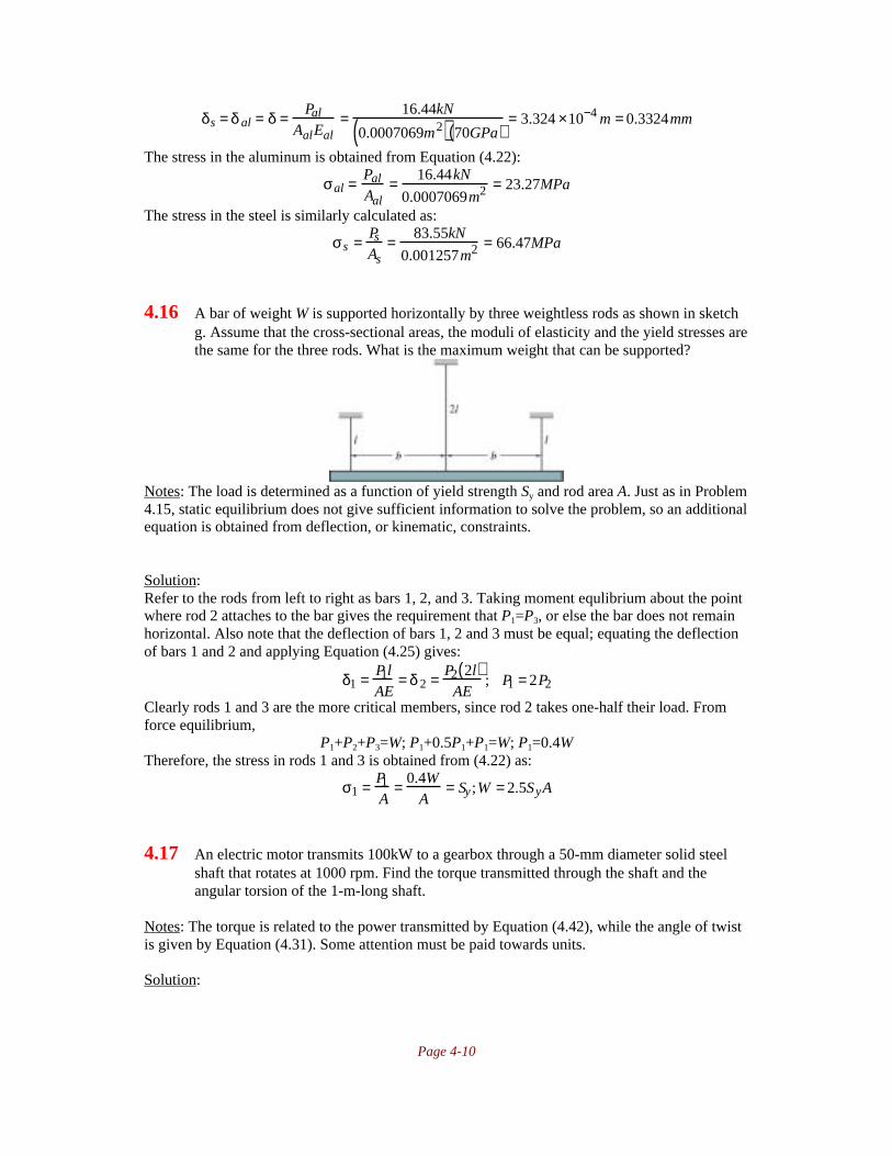
Page 4-10
δs = δ al = δ = Pal
AalEal= 16.44kN
0.0007069m2( ) 70GPa( )= 3.324 ×10⁻⁴ m = 0.3324mm
The stress in the aluminum is obtained from Equation (4.22):
σal = Pal
Aal= 16.44kN
0.0007069m2 = 23.27MPa
The stress in the steel is similarly calculated as:
σs = Ps
As= 83.55kN
0.001257m2 = 66.47MPa
4.16 A bar of weight W is supported horizontally by three weightless rods as shown in sketchg. Assume that the cross-sectional areas, the moduli of elasticity and the yield stresses arethe same for the three rods. What is the maximum weight that can be supported?
Notes: The load is determined as a function of yield strength Sy and rod area A. Just as in Problem4.15, static equilibrium does not give sufficient information to solve the problem, so an additionalequation is obtained from deflection, or kinematic, constraints.
Solution:Refer to the rods from left to right as bars 1, 2, and 3. Taking moment equlibrium about the pointwhere rod 2 attaches to the bar gives the requirement that P1=P3, or else the bar does not remainhorizontal. Also note that the deflection of bars 1, 2 and 3 must be equal; equating the deflectionof bars 1 and 2 and applying Equation (4.25) gives:
δ1 = P1lAE
= δ 2 = P2 2l( )AE
; P1 = 2P2
Clearly rods 1 and 3 are the more critical members, since rod 2 takes one-half their load. Fromforce equilibrium,
P1+P2+P3=W; P1+0.5P1+P1=W; P1=0.4WTherefore, the stress in rods 1 and 3 is obtained from (4.22) as:
σ1 = P1
A= 0.4W
A= Sy ;W = 2.5SyA
4.17 An electric motor transmits 100kW to a gearbox through a 50-mm diameter solid steelshaft that rotates at 1000 rpm. Find the torque transmitted through the shaft and theangular torsion of the 1-m-long shaft.
Notes: The torque is related to the power transmitted by Equation (4.42), while the angle of twistis given by Equation (4.31). Some attention must be paid towards units.
Solution:
Page 4-11
The angular velocity of the shaft is ω=1000rpm=104.7rad/s. Therefore, Equation (4.42) gives thetorque as:
T =hp
ω= 100kW
104.7rad / s= 955Nm
From the inside front cover, the elastic modulus of steel is 207GPa, and Poisson’s ratio is 0.3.Therefore, the shear modulus is, from Equation (B.53) on page 918:
G = E2 1+ν( ) = 207GPa
2 1+ 0.3( ) = 79.6GPa
The polar moment of inertia for the round cross section is, from Table 4.1 on page 148,
J = πr4
2= π 0.025m( )4
2= 6.136×10⁻⁷ m4
The angle of twist is then obtained from Equation (4.31) as:
θ = TlJG
= 955Nm( ) 1m( )6.136×10⁻⁷ m4( ) 79.6GPa( )
= 0.01955rad = 1.12°
4.18 The torque-transmitting shaft in Problem 4.17 is too heavy for the application, so it isexchanged for a circular tube having a 50-mm outside diameter and a 40-mm insidediameter. Find the angular torsion of the tube-formed shaft, which is 1m long, when100kW is transferred at 1000 rpm. The shear modulus is 80,000N/mm
2. Also, find the
maximum shear stress in the tube and the percentage of weight decrease from the solidshaft.
Notes: The approach is similar to Problem 4.17, which is not needed to solve this problem. Thetorque is related to the power transmitted by Equation (4.42), while the angle of twist is given byEquation (4.31). The maximum shear stress is obtained from Equation (4.34). Some attentionmust be paid towards units.
Solution:The angular velocity of the shaft is ω=1000rpm=104.7rad/s. Therefore, Equation (4.42) gives thetorque as:
T =hp
ω= 100kW
104.7rad / s= 955Nm
The polar moment of inertia for the tube is, from Table 4.1 on page 148,
J =π ro
4 − ri4[ ]
2=
π 0.025m( )4 − 0.020 m( )4[ ]2
= 3.623×10⁻⁷m4
The angle of twist is then obtained from Equation (4.31) as:
θ = TlJG
= 955Nm( ) 1m( )3.623 ×10⁻⁷ m4( ) 80GPa( )
= 0.0329rad =1.89°
The weight ratio of the tube to the solid shaft is:
Wtube
Wsolid= ρAt l
ρAsl=
π ro2 − ri
2( )πro
2 = 0.025m( )2 − 0.020m( )20.025m( )2 = 0.36
Or in other words, there was a 64% weight savings.

Page 4-12
4.19 A torque transmitting, hollow steel shaft with a circular cross section has an outerdiameter of 50mm and an inner diameter of 40mm. Find the maximum length possiblefor the shaft if the torsion should be below 10° at a torque of 2000 Nm.
Notes: This is similar to problems 4.17 and 4.18. The length is obtained from Equation (4.31), butthe angle of twist must be expressed in radians.
Solution:From the inside front cover, the elastic modulus of steel is E=207GPa, and Poisson’s ratio isν=0.3. Therefore, the shear modulus is, from Equation (B.53) on page 918:
G = E2 1+ν( ) = 207GPa
2 1+ 0.3( ) = 79.6GPa
The polar moment of inertia for the round cross section is, from Table 4.1 on page 148,
J =π ro
4 − ri4[ ]
2=
π 0.025m( )4 − 0.020 m( )4[ ]2
= 3.623×10⁻⁷m4
The angle of twist is 10°=0.1745rad. Therefore, Equation (4.31) can be solved for the length as:
θ = TlJG
; l = θJGT
=0.1745rad( ) 3.623×10⁻⁷ m4( ) 79.6GPa( )
2000Nm= 2.52m
4.20 The bronze statue described in Problem 4.13 is asymmetrical, so that when a gale forcewind blows against it, a twisting torque of 1000 Nm is applied to the tube. Calculate howmuch the statue twists. The tube’s wall thickness, 6mm at the top and 12 mm at thebottom, is assumed to be proportional to its diameter.
Notes: This problem requires the determination of the diameter as a function of tube height,which then allows the determination of polar moment of inertia as a function of height. Equation(4.31) gives the angle of twist.
Solution:For the AISI 316 stainless steel, E=193GPa and ν=0.3 as found on the inside front cover.Equation (B.53) on page 918 gives the shear modulus as:
G = E2 1+ν( ) = 193GPa
2 1+ 0.3( ) = 74.23GPa
The outer diameter of the tube, in meters, is
d0 x( ) = 0.200 1 + x3
The inner diameter in meters is
di x( ) = 0.2− 0.012( ) 1+ x3
= 0.188 1+ x
3
The polar moment of inertia is, using the data from Table 4.1 on page 148,
J x( ) =π32
do4 − d i
4( ) =π32
1+x
3
4
0.24 − 0.1884( ) = 3.44 ×10⁻⁵( ) 1+x
3
4
Therefore, the angle of twist is
θ =T
G
dx
J x( )0
3m∫ =
1000Nm
74.23GPa
dx
3.44 × 10⁻⁵( ) 1+x
3
4 =0
3m∫ 3.423× 10⁻⁴rad = 0.0196°
Page 4-13
4.21 Determine the minimum diameter of a solid shaft used to transmit 500kW of power froma 2000 rpm motor so that the shear stress does not exceed 50MPa.
Notes: The torque is related to the power transmitted by Equation (4.42). The maximum shearstress is given by Equation (4.34). This should be expressed as a function of the diameter, setequal to the allowable stress of 50MPa, and then solved for the diameter.
Solution:The angular velocity of the shaft is ω=2000rpm=209rad/s. Therefore, the torque transmitted isgiven by Equation (4.42) as:
T =hp
ω= 500kW
209rad / s= 2390Nm
From Table 4.1, the polar moment of inertia for a round cross section is J=πd4/32. c from
Equation (4.34) is d/2. Therefore, the diameter is obtained form the maximum shear stress from(4.34):
τmax = cTJ
= d / 2( ) 2390Nm( )πd4 / 3 2( ) = 38240Nm
πd3 = 50MPa; d3 = 38,240 Nmπ 50MPa( ) = 0.000243m3
or d=0.0624m=62.4mm
4.22 A steel coupling is used to transmit a torque of 30,000Nm. The coupling is connected tothe shaft by a number of 5mm diameter bolts placed equidistant on a pitch circle of 0.3mdiameter. The inner diameter of the coupling is 0.1m. The allowable shear stress on thebolts is 500MPa. Find the minimum number of bolts needed.
Notes: The bolts are assumed small enough and placed at a large enough diameter so that theshear stress is assumed constant across a bolt section. One must merely apply torque equilibriumto solve this problem.
Solution:If the bolt diameter is 5mm, then the cross sectional area is A=πd
2/4=1.963x10
-5m
2. If the
allowable shear stress on a bolt is 500MPa, then the force transmitted by each bolt isF=τA=(500MPa)(1.963x10
-5m
2)=9817N.
If there are n bolts on the 0.3m diameter, then the torque they can support is nF(0.15m). Equatingthis to the applied torque yields:
T = nF 0.15m( ); 30 ,000Nm = n 9817N( ) 0.15m( ); n = 20.3Therefore, 21 bolts are needed.
4.23 A shaft and a coupling are to transmit 50kW of power at an angular speed of 1000rpm.The coupling is connected to the shaft by 10 bolts, 20mm in diameter, placed on a pitchcircle of 200mm. For an allowable stress on the bolts of 100MPa, are the bolts able totransfer this power?
Notes: This problem is similar to Problem 4.22. The torque transmitted is calculated fromEquation (4.42). Torque equilibrium is then applied to solve the problem.

Page 4-14
Solution:
The cross sectional area of each bolt is A=πd2/4=3.14x10
-4m
2. If the allowable shear stress on a
bolt is 100MPa, then the force transmitted by each bolt isF=τA=(100MPa)(3.14x10
-4m
2)=31.4kN.
If there are 10 bolts on the 0.2m diameter, then the torque they can support is10F(0.1m)=31.4kNm. The angular speed is 1000rpm=104.7rad/s. The applied torque is calculatedfrom Equation (4.42) as:
T =hp
ω= 50kW
104.7rad / s= 477Nm
This is a much lower torque than the bolts can safely transfer.
4.24 A beam transmitting a bending moment M of 5000Nm has a square cross section 100 by100mm. The weight is decreased by making either one or two axial circular holes alongthe beam. Determine whether one or two holes gives the lowest weight for the beam at agiven bending stress. Neglect the transverse shear stress.
Notes: The ratio of moment of inertia of the section to the area can be compared for the twoalternatives; this is because the extreme fiber distance, the beam length and material are allconstant.
Solution:
The two alternatives are sketched above. The moments of inertia and areas for the two shapes are:
I1 =a4
12−
2π4
r4 =a4
12−
π4
a
4
4
2( ) =a4
4
1
3−
π128
A1 = a2 − 2πa
4
2
= a2 1 −π8
I2 =a4
12−
π4
r 4 =a4
12−
π4
a
2
4
=a4
4
1
3−
π16
A2 = a2 − πa
2
2
= a2 1−π4
Therefore, the following ratios can be written:
I1A1
=
a4
4
1
3− π
128
a2 1 − π8
=a2 1
3− π
128
4 − π2

Page 4-15
I2
A2=
a4
4
1
3− π
16
a2 1 − π4
=a2 1
3− π
16
4 − π
Therefore, comparing the two cases:
I1 / A1
I2 / A2=
a2 1
3− π
128
4 − π2
4 − π
a2 1
3− π
16
= 0.797
Therefore, the beam with two holes gives the lower weight at a given bending moment.
4.25 A straight beam is loaded at the ends by moments M: the area moment of inertia for the
beam is I=a3b/12. Find the bending stress distribution in the beam when M=1000Nm,
a=3cm, and b=6cm. Also, find the radius of curvature to which the beam is bent. The
beam’s modulus of elasticity is 2.05 x 10¹¹
Pa.
Notes: Equation (4.49) gives the bending stress distribution; Equation (4.50) gives the radius ofcurvature.
Solution:
From the given data, the moment of inertia is I=a3b/12=(0.03m)
3(0.06m)/12=1.35x10
-7m
4.
Therefore, the bending stress distribution is given by Equation (4.49) as:
σ = MyI
= 1000Nm( )y1.35 ×10−7 m3 = 7.41GN / m3( )y
The maximum bending stress occurs for y=a/2, or σmax=111MPa. The radius of curvature iscalculated from Equation (4.50) as:
1r
= MEI
; r = EIM
=205GPa( ) 1.35 ×10⁻⁷m4( )
1000Nm= 28.1m
4.26 The beam in Problem 4.25 is bent in a perpendicular direction so that I=ab3/12. Find the
bending stress distribution and the radius of curvature to which the beam is bent.
Notes: This is solved in the same manner as Problem 4.25, except that the values of a and b havechanged.
Solution:
From the given data, the moment of inertia is I=ab3/12=(0.03m)(0.06m)
3/12=5.4x10
-7m
4.
Therefore, the bending stress distribution is given by Equation (4.49) as:
σ = MyI
= 1000Nm( )y5.4 ×10−7m3 = 1.85GN / m3( )y
The maximum bending stress occurs for y=b/2, or σmax=55.5MPa. The radius of curvature iscalculated from Equation (4.50) as:
1r
= MEI
; r = EIM
=205GPa( ) 5.4 ×10⁻⁷ m4( )
1000Nm= 110.7m

Page 4-16
4.27 A curved bar has a rectangular cross section with height h=r0-ri=50mm and widthb=100mm. Its inner radius is 100mm. Find the distance between the neutral axis and thecentroid.
Notes: This problem merely requires application of Equation (4.58).
Solution:Note that ro=ri+h=150mm. The eccentricity is given by Equation (4.58) as:
e = ri + ro2
− ro − ri
lnror1
= 100mm +150mm2
− 150mm −100mm
ln150
100
= 1.68mm
4.28 The curved bar is loaded with a bending moment of 3000 Nm. Find the stress at theinnermost and outermost radii.
Notes: These stresses are obtained from Equations (4.65) and (4.66). The results from Problem4.27 are used to obtain this solution.
Solution:As derived in Problem 4.27, e=1.68mm=0.00168m. With a height of 50mm and a width of
100mm, the cross sectional area is A=0.005m2. Therefore, the stress at the inner surface is, from
Equation (4.65),
σi = − Mci
Aeri= − 3000Nm( ) 0.025m − 0.00168m( )
0.005m2( ) 0.00168m( ) 0.1m( )= −83.29MPa
The stress at the outer surface is, from Equation (4.66),
σo = Mco
Aero= 3000Nm( ) 0.025m + 0.00168m( )
0.05m2( ) 0.00168m( ) 0.15m( )= 63.52MPa
4.29 Two beams with rectangular cross sections axb are placed on top of each other to form abeam having height 2a and width b. Find the area moments of inertia Ix and Iy for the twobeamsa) When they are welded together along the lengthb) When they are not welded together.
Notes: The implication is that if the beams are welded together they act as a single beam; if notwelded, they act as two individual beams.
Solution:If the beams are welded together, it is as if the cross section is of one material, so from Table 4.1,
Ix = bh3
12= b 2a( )3
12= 2ba3
3
Iy = b3h12
= b3 2a( )12
= b3a6

Page 4-17
If they are not welded together, then the moments of inertia are:
Ix = bh3
12+ bh3
12= 2b a( )3
12= ba3
6
Iy = b3h12
+ b3h12
= b3 a( )12
+ b3 a( )12
= b3a6
4.30 Two thin steel plates having width b/20 and height 5a are placed one at each side of thetwo beams in Problem 4.29. See sketch h. Find the moments of inertia around the x and yaxesa) When the plates are not welded together.b) When they are welded together as shown in sketch hc) When they are welded together to form a closed tube 5ax1.1b.
Notes: The approach is the same as in Problem 4.29.
Solution:If the plates are not welded together, then the moments of inertia of the individual beams areadded together. Ix is calculated as
Ix = 21
12
b
20
5a( )3 + 2
ba3
12=1.21ba3
For Iy, note that even though the thin plates are not welded to the other plates, they still areseparated, so their moment of inertial about the y-axis needs to be evaluated using the Parallel-Axis Theorem. Therefore,
Iy = 21
12
ab3 + 2
112
5a( ) b
20
3
+ 2 5a( ) b20
b
2+ b
40
2
= 0.304ab3
If the plates are welded together, then the plates can be taken as one area. Ix is then calculated as:
Ix = 21
12
b
20
5a( )3 + 2
112
b( ) 2a( )3 = 2.375ba3
and by taking advantage of the geometry, Iy is
Iy = 112
5a( ) b + b20
+ b20
3
− 21
12
1.5a( ) b( )3 = 0.304ab3
Note that Iy has not changed appreciably; this is attributable to the very thin plates used at theends of the axb plates.
If they are welded to form a closed tube, then Ix is given by:
Ix = 112
1.1b( ) 5a( )3 − 112
b( ) 3a( )3 = 9.21ba3
and Iy is unchanged; it has the value 0.304ab3.

Page 4-18
4.31 A cantilevered beam with a rectangular cross section is loaded by a force perpendicular tothe beam centerline at the free end. The cross section is 75 mm high and 25 mm wide.The vertical load at the beam end is 20,000N. Calculate how long the beam should be togive tensile and compressive stresses 10 times higher than the maximum shear stress.Also, calculate these stresses.
Notes: Equation (4.48) gives the maximum bending stress, and Table 4.3 gives the maximumshear stress.
Solution:
For the cross section defined, the moment of inertia is (0.025m)(0.075m)3/12=8.79x10
-7m
4. For a
cantilever with a load P at the free end, the maximum moment is M=Pl=(20,000N)l. Themaximum shear is V=P=20,000N. Therefore, the maximum shear stress is, from Table 4.3 onpage 170,
τmax = 3V2A
= 3 20 ,000N( )2 0.025m( ) 0.075m( ) =16MPa
Since the maximum normal stress is ten times the maximum shear stress, it is 160MPa. FromEquation (4.48),
σmax = McI
=20,000 N( ) l( ) 0.075m
2
8.79 ×10⁻⁷m4 = 160MPa; l = 0.1875m = 187.5mm
4.32 A cantilevered beam with a circular-tube cross section has an outer diameter of 100mmand a wall thickness of 10mm. The load perpendicular to the beam is 15,000N, and thebeam is 1.2m long from the point of force to the wall where the beam is fastened.Calculate the maximum bending and shear stresses.
Notes: The approach is similar to Problem 4.31. Equation (4.48) gives the maximum bendingstress, and Table 4.3 gives the maximum shear stress.
Solution:The maximum moment occurs at the wall and equals M=Pl=(15,000N)(1.2m)=18kNm. Themaximum shear force is V=P=15kN. The moment of inertia of the beam is (see Table 4.1 on page148):
I = π64
do4 − di
4( ) = π64
0.1m( )4 − 0.08m( )4( ) = 2.898×10⁻⁶ m4
From Table 4.3 on page 170, the maximum shear stress is:
τmax = 2VA
= 2 15kN( )π4
0.1m( )2 − 0.08m( )2( )= 10.61MPa
From Equation (4.48),
σ = McI
= 18kNm( ) 0.05m( )2.898×10⁻⁶ m4 = 310.5MPa
4.33 A fishing rod is made of glass-fiber-reinforced plastic in the form of a tube having anouter diameter of 10 mm and a wall thickness of 1.5mm. The glass fibers are parallel to

Page 4-19
the tube axis, so that the bending shear stress is carried by the plastic and the bendingstresses are carried by the fibers. The fishing rod is 2m long. Determine whether the rodfails from tensile stresses in the fibers or from shear overstressing in the plastic. Thebending strength of the fiber-reinforced plastic is 800MPa, and its shear strength is3.2MPa.
Notes: The bending normal stresses are calculated from Equation (4.48) and the maximum shearstress is obtained from Table 4.3 on page 170. Comparing the critical load for the two failuremodes allows solution of the problem.
Solution:The maximum moment occurs at the wall and equals M=Pl=(P)(2m). The maximum shear forceis V=P. The moment of inertia of the rod is (see Table 4.1 on page 148):
I = π64
do4 − di
4( ) = π64
0.01m( )4 − 0.007m( )4( ) = 3.73 ×10⁻¹⁰ m4
From Table 4.3 on page 170, the maximum shear stress is tmax=2V/A, so that the largest loadthat can be applied at the end of the rod is:
τmax = 2PA
= 3.2MPa; P =3.2MPa( ) π
40.01m( )2 − 0.007m( )2( )
2= 64N
The maximum load that can be supported without causing bending failure is obtained fromEquation (4.48), recognizing the maximum allowable bending stress is 80MPa:
σmax = McI
= P 2m( ) 0.005m( )3.73 ×10⁻¹⁰m4 = 800MPa ;P = 29.8N
Therefore, the rod fails first from overstressing the fibers.
4.34 Two aluminum beams, like the one shown in Fig. 4.6, are welded together to form aclosed cross section with dimensions 240 by 80mm. The weld was badly done, so that thewall is only 2 mm thick instead of 8mm. The allowable shear stress in the weld is 50MPa,whereas the maximum allowable bending stress is 150MPa. Find whether the 2-m-longbeam fails first at the outermost fibers or at the welds.
Notes: The moment of inertia and the first moment have to be calculated for the shape. Themaximum load is then calculated for the two failure modes as in Problem 4.33. The onlydifference is that Equation (4.67) is needed to obtain the maximum shear stress.
Solution:The moment of inertia for the cross section is:
I = b1h13
12− b2h2
3
12= 0.08m( ) 0.24m( )3
12− 0.064m( ) 0.224m( )3
12= 3.222 ×10⁻⁵ m4
For a cantilever, the maximum moment is M=Pl=(2m)P. Therefore, Equation (4.48) gives:
σmax = McI
= PlcI
; P = σ maxIlc
=150MPa( ) 3.222× 10⁻⁵ m4( )
2m( ) 0.120m( ) = 20.14kN
The first moment of area is calculated as:
Q = 0.06m( ) 0.08m( ) 0.12m( )− 0.056m( ) 0.064 m( ) 0.112m( ) =1.746 ×10⁻⁴m3
Equation (4.67) then gives:

Page 4-20
τmax = VQIwt
; V = τmaxIwt
Q=
50MPa( ) 3.22 ×10⁻⁵ m4( ) 0.004m( )1.746 ×10⁻⁴ m3 = 36.9kN
The weld fails first.
4.35 To decrease as much as possible the weight of beams subjected to bending, the center ofgravity of the cross section is placed as far away from the beam center of gravity aspossible. A beam supporting a floor has a cross section as shown in sketch i. The bendingmoment acting on the beam is 3000Nm, and the shear force is 1000N. Calculate themaximum bending stress and maximum shear stress.
Notes: The moment of inertia and the first moment have to be calculated for the shape. Themaximum load is then calculated for the two failure modes as in Problem 4.34.
Solution:The moment of inertia for the cross section is:
I = b1h13
12− b2h2
3
12= 0.100m( ) 0.16m( )3
12− 2
0.048m( ) 0.14m( )3
12=1.218 ×10⁻⁵m4
Therfore, Equation (4.48) gives:
σmax = McI
= 3000Nm( ) 0.08m( )1.218×10⁻⁵ m4 = 19.7MPa
The first moment of area is calculated as:Q=(0.035m)(0.004m)(0.07m)+(0.01m)(0.1m)(0.075m)=8.48x10
-5m
3
Equation (4.67) then gives:
τmax = VQIwt
=1000N( ) 8.48 ×10⁻⁵m3( )1.218×10⁻⁵ m( ) 0.004m( )
= 1.74MPa

Page 5-1
Chapter 5Deformation
5.1 A beam is loaded by a concentrated bending moment M at the free end. The size of themoment equals the maximum moment, or Pl. Find the vertical and angular deformationsalong the beam by using the equation of the elastic line, Eq. (5.3).
Notes: This problem requires integration of Equation (5.3) twice, and then application ofboundary conditions for a cantilever.
Solution:Equation (5.3) gives
∂ 2y
∂x2 = − MEI
= − PlEI
Integrating twice,∂y
∂x= − Pl
EIx + C1
y = − Pl2EI
x2 + C1x + C2
Referring to the sketch above, the boundary conditions are dy/dx=0 at x=0 and y=0 at x=0. Thefirst boundary condition gives C1=0. The second gives C2=0. Therefore, the angular deflectionand the vertical deflection along the beam are given by (see Equation (5.6)):
∂ydx
= θ = − PlEI
x; y = − Pl2EI
x2
The maximum vertical deflection occurs at x=l and is
ymax = − Pl3
2EI
5.2 A simply supported beam of length l carries a force P. Find the ratio between the bendingstresses in the beam when P is concentrated in the middle of the beam and evenlydistributed along it. Use the moment-curvature relation given in Equation (5.3). Also,calculate the ratio of deformations at the middle of the beam.
Notes: To determine the maximum stresses, the largest moment must be determined. The shearand moment diagrams are found as in Chapter 2. Integration of Equation (5.3) then gives theanswer.
Solution:The sketch and shear and moment diagrams for the two cases are shown below. In both cases, themaximum stress and deflection are at the center.

Page 5-2
I. Point Load CaseFor the point load case, moment equation up to x=l/2 is M(x)=-Px/2. The maximum moment, atx=l/2, is Mmax=-Pl/4. Therefore, from Equation (5.3), and integrating twice,
d2y
dx 2 = − MEI
= Px2EI
; dydx
= Px2
4EI+ C1; y = Px3
12EI+ C1x + C2
The boundary conditions are that y=0 at x=0 and dy/dx=0 at x=l/2. The first boundary conditiongives C2=0. The second gives:
dydx
= Px2
4EI+ C1; 0= Pl2
16EI+ C1; C1 = − Pl2
16EITherefore, the deflection is
y = Px3
12EI− Pl2
16EIx = Px
4EIx2
3− l2
4
The maximum deflection occurs at x=l/2 and is:
ymax = Pl8EI
l2
12− l2
4
= − Pl3
48EI
II. Distributed loadFor this case, the moment distribution is
M = P2
x2
l− x
The maximum moment, evaluated at x=l/2, is Mmax=-Pl/8. From Equation (5.3), and integratingtwice, gives
d2y
dx 2 = − MEI
= P2EI
x − x2
l
;
dydx
= P2EI
x2
2− x3
3l
+ C3 ; y = P
2 EIx3
6− x4
12l
+ C3x + C4
The first boundary condition is that at x=0, y=0. Therefore, C4=0. The second boundary conditionis that dy/dx=0 at x=l/2, so that
dydx
= P2 EI
x2
2− x3
3l
+ C3; 0 =
P2EI
l2
8− l3
24l
+ C3; C3 = − Pl2
24EI
Therefore the deflection, and the maximum value evaluated at x=l/2 are:
y =P
2EI
x3
6−
x4
12l
−
Pl2
24EIx =
P
12EIx3 −
x4
2l−
l2x
2
; ymax = yx=l /2 = −
5Pl3
384EI

Page 5-3
III. ComparisonThe ratio of the maximum stresses, from Equation (4.48) gives:
σconc
σ dist=
MconccI
MdistcI
= Mconc
Mdist= −Pl / 4
−Pl / 8= 2
The ratio of maximum deflections is:
yconc
ydist=
− Pl3
48EI
− 5Pl3
384EI
= 384240
= 1.6
5.3 A simply supported beam with length l is centrally loaded with a force P. How large amoment needs to be applied at the ends of the beama) To maintain the slope angle of zero at the supports?b) To maintain the midpoint of the beam without deflection when the load is applied?Use the equation of the elastic line, Eq. (5.3).
Notes: The problem which must be solved is that of a simply supported beam with both aconcentrated load at the center and a moment applied at both ends. Once the elastic equation ofthe beam is determined, the problem can be solved.
Solution:The beam and moment diagrams are obtained as in Chapter 2. The moment distribution is givenby
M=M0-Px/2Therefore, from Equation (5.3) and integrating twice,
d2y
dx 2 = − M x( )EI
= Px2EI
− M0
EI;
dydx
= Px2
4EI− M0x
EI+ C1; y = Px3
12EI− M0x2
2EI+ C1x + C2
The boundary conditions are y=0 at x=0 and dy/dx=0 at x=l/2. The first boundary condition givesC2=0. The second gives:
0 = Pl 2
16EI− M0l
2EI+ C1; C1 = 1
EIM0l
2− Pl2
16
Therefore, the angular deflection and the vertical deflection are given by:
dydx
= Px2
4EI− M0x
EI+ 1
EIM0l
2− Pl2
16
=
1EI
Px2
4− l2
16
+ M0
l2
− x
y = Px3
12EI− M0x2
2EI+ 1
EI
M0l
2− Pl2
16
x = x
EIP
x2
12− l2
16
+ M0
l
2− x
2
To maintain a slope of zero at the supports, set dy/dx=0, x=0, and solve for M0 to give:
dy
dx= 0 =
1
EIP −
l2
16
+ M0
l
2
; M0 =
Pl
8
To have a deflection of zero at the midpoint, set y=0 at x=l/2 and solve for M0:

Page 5-4
y = 0 = l2EI
Pl2
48− l2
16
+ M0
l2
− l4
; M0 = 8Pl2
48l= Pl
6
5.4 Find the relationship between P and w0 so that the slope of the deflected beam is zero atthe supports for the loading conditions shown in sketch a. Assume that E and A areconstant.
Notes: This solution uses singularity functions, although it could be solved through the othermethods in Chapter 2.
Solution:The reactions are shown on the beam above in red. Due to symmetry, the reaction forces areequal and are:
R = P2
+ w0l4
Using singularity functions, the load function is given by:
q x( ) = −w0 x 0 + 2w0
lx 1 − 2w0
lx − l
2
1+ R x − l
2
−1− P x − l −1
+R x − 3l
2
−1− 2w0
lx − 3l
2
1+ 2w0
lx − 2l 1 + w0 x − 2l 0
Therefore, From Equation (2.4),
−V x( ) = −w0 x 1+ w0
lx 2 − w0
lx − l
2
2+ R x − l
2
0− P x − l 0
+R x − 3l
2
0− w0
lx − 3l
2
2+ w0
lx − 2 l 2 + w0 x − 2l 1
And from Equation (2.5),
−M x( ) = − w0
2x 2 + w0
3lx 3 − w0
3lx − l
2
3+ R x − l
2
1− P x − l 1
+R x − 3l
2
1− w0
3lx − 3l
2
3+ w0
3lx − 2l 3 + w0
2x − 2 l 2
From Equation (5.3),
EId2y
dx2 = −M x( )Continuing the integration,
EIdydx
= − w0
6x 3 + w0
12lx 4 − w0
12 lx − l
2
4+ R
2x − l
2
2− P
2x − l 2
+ R
2x − 3l
2
2− w0
12lx − 3 l
2
4+ w0
12lx − 2l 4 + w0
6x − 2l 3 + C1

Page 5-5
EIy = − w0
24x 4 + w0
60 lx 5 − w0
60lx − l
2
5+ R
6x − l
2
3− P
6x − l 3
+ R
6x − 3 l
2
3− w0
60lx − 3l
2
5+ w0
60lx − 2 l 5 + w0
24x − 2l 4 + C1x + C2
The boundary conditions are that y=0 at x=l/2 and y=0 at 3l/2. The first boundary condition gives:
EIy = −w0
24l2
4
+ w0
60ll2
5
+ C1l2
+ C2
The second boundary condition gives
EIy = −w0
243l2
4
+ w0
60 l3l2
5
− w0
60ll( )5 + R
6l( )3 − P
6l2
3
+ C1l2
+ C2
Solving for C1 and C2 gives:
C1 = 55960
w0l3 − Pl2
16
C2 = − 51w0l4
1920+ Pl3
32If the slope is zero at x=l/2,
EIdydx
= 0 = − w0
6l2
3
+ w0
12ll2
4
+ C1 = −w0
6l2
3
+ w0
12ll2
4
+ 55960
w0l3 − Pl2
16Or, simplifying the equation,
0 = 20w0 l3
480− Pl2
16; P = 2w0 l
3
5.5 Given a simply supported beam with two concentrated forces acting on it as shown insketch h, determine the expression for the elastic deformation of the beam for any x byusing singularity functions. Assume that E and I are constant. Also, determine thelocation of maximum deflection and derive an expression for it.
Notes: This problem uses an approach similar to Problem 5.4.
Solution:From symmetry, the reactions are equal and are equal to R1=R2=P. Therefore, the load functionin terms of singularity functions is:
q x( ) = P x −1 − P x − a −1 − P x − l + a −1 + P x − l −1 = P x −1 − x − a −1 − x − l + a −1 + x − l −1[ ]From Equation (2.4),
−V x( ) = P x 0 − x − a 0 − x − l + a 0 + x − l 0[ ]And from Equation (2.5),

Page 5-6
−M x( ) = P x 1 − x − a 1 − x − l + a 1 + x − l 1[ ]From Equation (5.3),
EId2y
dx2 = −M x( ) = P x 1 − x − a 1 − x − l + a 1 + x − l 1[ ]Therefore, integrating twice,
EIdydx
= P2
x 2 − x − a 2 − x − l+ a 2 + x − l 2[ ]+ C1
EIy = P6
x 3 − x − a 3 − x − l+ a 3 + x − l 3[ ]+ C1x + C2
The boundary conditions are y=0 at x=0 and y=0 at x=l. The first boundary condition gives C2=0.The second gives:
EIy = 0 = P6
l3 − l − a( )3 − a3[ ] + C1l; C1 = −P l − a( )a2
Therefore, the deflection is
EIy = P6
x 3 − x − a 3 − x − l+ a 3 + x − l 3[ ]− P l − a( )a2
x
The maximum value is at x=l/2, and is:
EIymax = P6
l2
3
− l2
− a
3
− P l − a( )al4
= P6
l2
3
− l2
− a
3
− 3al l − a( )2
5.6 For the loading condition described in sketch c, obtain the internal shear force V(x) andthe internal moment M(x) by using singularity functions. Draw V(x), M(x), θ(x) and y(x)as a function of x. Assume that w0=9kN/m and l=3m.
Notes: The statics of this problem are a little more difficult than for Problem 5.4 and 5.5, but themethod of solution is similar. The reaction forces are shown in red in the sketch above.
Solution:Summing moments about the left support,
M = 0 =∑ w0l3
l6
+ 1
2w0l3
4l
9
− R2 l; R2 = 7w0 l
54= 7 9kN / m( ) 3m( )
54= 3.5kN
Taking vertical force equilibrium,
F = 0∑ = R1 + R2 − w0l3
− w0l6
; R1 = w0l2
− R2 = 9kN / m( ) 3m( )2
− 3.5kN = 10kN
Therefore, the load distribution can be written in terms of singularity functions as:
Page 5-7
q x( ) = R1 x −1 − w0 x 0 + 3w0
lx − l
3
1− 3w0
lx − 2l
3
1+ R2 x − l −1
= R1 x −1 − w0 x 0 + 3w0l
x − l3
1− x − 2l
3
1
+ R2 x − l −1
From Equation (2.4),
−V x( ) = R1 x 0 − w0 x 1 + 3w0
2 lx − l
3
2
− x − 2l3
2
+ R2 x − l 0
And from Equation (2.5),
−M x( ) = R1 x 1 − w0
2x 2 + 3w0
6lx − l
3
3
− x − 2l3
3
+ R2 x − l 1
The shear and moment diagrams are sketched below:
From Equation (5.3),
EId2y
dx2 = −M x( ) = R1 x 1 − w0
2x 2 + 3w0
6lx − l
3
3
− x − 2l3
3
+ R2 x − l 1
Therefore, integrating twice,
EIdydx
= R1
2x 2 − w0
6x 3 + 3w0
24lx − l
3
4
− x − 2l3
4
+ R2
2x − l 2 + C1
EIy = R1
6x 3 − w0
24x 4 + 3w0
120 lx − l
3
5
− x − 2l3
5
+ R2
6x − l 3 + C1x + C2
Substituting for w0, R1, R2 and l,
EIy = 10kN6
x 3 − 9kN / m24
x 4 + 27kN / m360m
x − l3
5
− x − 2l3
5
+ 3.5kN6
x − l 3 + C1x + C2
The boundary conditions are y=0 at x=0 and y=0 at x=l. The first boundary condition gives C2=0.The second gives:
EIy = 0 = 10kN6
3m( )3 − 9kN / m24
3m( )4 + 27kN / m360m
2m( )5 − 1m( )5[ ]+ C1 3m( );C1 = −5.65kNm2
Therefore, the angular deflection and vertical deflection relationships are:
EIdydx
= EIθ = R1
2x 2 − w0
6x 3 + 3w0
24lx − l
3
4
− x − 2l3
4
+ R2
2x − l 2 − 5.65kNm2
EIy = 10kN6
x 3 − 9kN / m24
x 4 + 27kN / m360m
x − l3
5
− x − 2l3
5
+ 3.5kN6
x − l 3 − 5.65kNm2x
These are sketched below.

Page 5-8
5.7 A simply supported bar is shown in sketch d with w0=4kN/m and l=12m.a) Draw the free body diagram of the bar.b) Use singularity functions to determine shear force, bending moment, slope anddeflection.Provide both tabular results and a diagram of the shear force, the bending moment, theslope and the deflection.
Notes: This problem is very similar to Problem 5.6. The reaction forces are shown in red in thesketch above.
Solution:Summing moments about the left support,
M = 0 =∑ w0l4
l
3
+ w0l
8
7l
12
− R2 l; R2 = w0l
112
+ 796
= 4kN / m( ) 12m( ) 5
32
= 7.5kN
Taking vertical force equilibrium,
F = 0 =∑ − w0 l4
− w0l
8
+ R1 + R2 ; R1 = 3w0 l
8− R2 = 3 4kN / m( ) 12m( )
8− 7.5kN = 10.5kN
Therefore, the load distribution can be written in terms of singularity functions as (note thedirection of positive y):
q x( ) = −R1 x −1 + w0
l / 2( )x 1 − w0
l / 2( )x − l
2
1− w0
l / 4( )x − l
2
1+ w0
l / 4( )x − 3l
4
1− R2 x − l −1
= −R1 x −1 + 2w0
lx 1 − x − l
2
1
− 2 x − l2
1
+ 2 x − 3l4
1
− R2 x − l −1
From Equation (2.4),
−V x( ) = −R1 x 0 + w0
lx 2 − x − l
2
2
− 2 x − l2
2
+ 2 x − 3l4
2
− R2 x − l 0
And from Equation (2.5),
−M x( ) = −R1 x 1 + w0
3lx 3 − x − l
2
3
− 2 x − l2
3
+ 2 x − 3l4
3
− R2 x − l 1
The shear and moment diagrams are sketched below:
From Equation (5.3),

Page 5-9
EId2y
dx2 = −M x( ) = −R1 x 1 + w0
3lx 3 − x − l
2
3
− 2 x − l2
3
+ 2 x − 3l4
3
− R2 x − l 1
Therefore, integrating twice,
EIdydx
= − R1
2x 2 + w0
12 lx 4 − x − l
2
4
− 2 x − l2
4
+ 2 x − 3 l4
4
− R2
2x − l 2 + C1
EIy = − R1
6x 3 + w0
60lx 5 − x − l
2
5
− 2 x − l2
5
+ 2 x − 3 l4
5
− R2
6x − l 3 + C1x + C2
Substituting for w0, R1, R2 and l,
EIy = −10.5kN
6x 3 + 4kN / m
60 12m( ) x 5 − x − l
2
5
− 2 x − l
2
5
+ 2 x − 3l
4
5
− 7.5kN
6x − l 3 + C1x + C2
The boundary conditions are y=0 at x=0 and y=0 at x=l. The first boundary condition gives C2=0.The second gives:
EIy = 0 = − 10.5kN6
12m( )3 + 4kN / m60 12m( ) 12m( )5 − 12m
2
5
− 212m
2
5
+ 212m
4
5
+ C1l; C1 =147.4kNm2
Therefore, the angular deflection and vertical deflection relationships are:
EIdydx
= −5.25kN x 2 + 1kN / m48m
x 4 − x − l2
4
− 2 x − l2
4
+ 2 x − 3 l4
4
− 3.75kN x − l 2 +147.4kNm2
EIy = −1.75kN x 3 + 1kN / m1 5 1 2m( ) x 5 − x − l
2
5
− 2 x − l2
5
+ 2 x − 3l4
5
−1.25kN x − l 3 +147.4kNm2
These are sketched below.
5.8 The simply supported beam in Problem 5.5 is altered so that instead of a concentratedforce P, a concentrated moment M is applied at the same location. The moments arepositive and act parallel with each other. Determine the deformation of the beam for anyposition x along it by using singularity functions. Assume that E and I are constant. Also,determine the location of the maximum deflection.
Notes: Finding the deformation equation uses the same approach as in Problems 5.4 through 5.7.This problem illustrates that determination of the maximum deflection using singularity functionsis fairly difficult, unless it is numerically determined.
Solution:Summing moments about the left support,
M∑ = 0 = M0 + M0 − R2 l; R2 = 2M0
lTaking vertical force equilibrium,
F∑ = 0 = R1 + R2; R1 = −R2 = −2M0
l

Page 5-10
Therefore, the load distribution can be written in terms of singularity functions as (note thedirection of positive y):
q x( ) = R1 x −1 + M0 x − a −2 + M0 x − l + a −2
Note that the terms at x=l have been ignored because they don’t affect the problem. FromEquation (2.4),
−V x( ) = R1 x 0 + M0 x − a −1 + M0 x − l + a −1
And from Equation (2.5),
−M x( ) = R1 x 1 + M0 x − a 0 + M0 x − l + a 0
From Equation (5.3),
EId2y
dx2 = −M x( ) = R1 x 1 + M0 x − a 0 + M0 x − l + a 0
Therefore, integrating twice,
EIdydx
= R1
2x 2 + M0 x − a 1 + M0 x − l + a 1 + C1
EIy = R1
6x 3 + M0
2x − a 2 + M0
2x − l + a 2 + C1x + C2
The boundary conditions are that y=0 at x=0 and y=0 at x=l. The first boundary condition givesC2=0. The second gives:
EIy = 0 = −2 M0
6ll3 + M0
2l − a( )2 + M0
2a2 + C1l; C1 = M0 a− a2
l− l
6
Therefore, substituting for C1 and R1, the deformation of the beam is given by
EIy = −2M06 l
x 3 + M02
x − a 2 + M02
x − l + a 2 + M0 a − a2
l− l
6
x
= M0 − x 3
3 l+ x − a 2
2+ x − l + a 2
2+ a − a2
l− l
6
x
and dy/dx is
EIdydx
= M0 − x 2
l+ x − a 1 + x − l + a 1 + a − a2
l− l
6
The maximum deflection occurs at dy/dx=0, but two intervals have to be examined. The first isfor x<a, so that the maximum deflection occurs at:
0 = − x 2
l+ a− a2
l− l
6
; x = la − a2 − l2
6
However, if a<x<l-a, setting dy/dx=0 yields:
EIdydx
= 0 = M0 − x2
l+ x − a + a − a2
l− l
6
; x2 − xl + a2 + l2
6= 0
Using the quadratic formula and simplifying,
x =l
21 −
1
3−
2a
l
2
The location of maximum deflection is one of these values. One can substitute into the deflectionequation to see which is larger, but if a>l/4, the maximum deflection occurs at x<a, and it islocated at x>a for a<l/4,

Page 5-11
5.9 The simply supported beam in Problem 5.8 has moments applied in opposite directions sothat the moment at x=a is M0 and at x=l-a is -M0. Find the elastic deformation of the beamby using singularity functions. Also, determine the location and size of the maximumdeflection.
Notes: This is a much simpler problem than 5.8, although the approach is the same.
Solution:Taking moment equilibrium about the left support,
ΣM=0=M0-M0-R2l; R2=0Taking force equilibrium,
ΣF=0=R1+R2; R1=0Therefore, the load intensity function is given by:
q x( ) = M0 x − a −2 − M0 x − l + a −2 = M0 x − a −2 − x − l + a −2[ ]From Equation (2.4),
−V x( ) = M0 x − a −1 − x − l + a −1[ ]And from Equation (2.5),
−M x( ) = M0 x − a 0 − x − l+ a 0[ ]From Equation (5.3),
EId2y
dx2 = −M x( ) = M0 x − a 0 − x − l+ a 0[ ]Therefore, integrating twice,
EIdydx
= M0 x − a 1− x − l+ a 1[ ]+ C1
EIy = M0
2x − a 2 − x − l+ a 2[ ]+ C1x + C2
The boundary conditions are y=0 at x=0 and y=0 at x=l. The first yields C2=0, the second yields
0 = M0
2l − a( )2 − a2[ ]+ C1l; C1 = M0 2a − l( )
2Therefore, the deflection is
EIy = M0
2x − a 2 − x − l+ a 2 + 2a − l( )x[ ]
The first derivative of this expression is:
EIdydx
= M0 x − a 1 − x − l + a 1 + 2a − l( )2
Setting this equal to zero yields, for x<a:2a − l
2= 0; a = l
2Therefore, the deflection is a maximum only if the moments are both applied at the same location,at the center of the beam. Otherwise, for a<x<l-a,
EIdydx
= 0 = M0 x − a( )1 + 2a − l( )2
; x − a + a − l
2= 0; x = l
2Therefore, the maximum deflection occurs at mid-span.
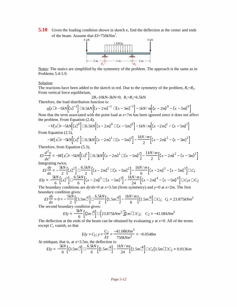
Page 5-12
5.10 Given the loading condition shown in sketch e, find the deflection at the center and endsof the beam. Assume that EI=750kNm
2.
Notes: The statics are simplified by the symmetry of the problem. The approach is the same as inProblems 5.4-5.9.
Solution:The reactions have been added to the sketch in red. Due to the symmetry of the problem, R1=R2.From vertical force equilibrium,
2R1-10kN-3kN=0; R1=R2=6.5kNTherefore, the load distribution function is:
q x( ) = −5kN x −1[ ] + 6.5kN x − 2m −1 + x − 5m −1[ ] − 1kN / m x − 2m 0 − x − 5m 0[ ]Note that the term associated with the point load at x=7m has been ignored since it does not affectthe problem. From Equation (2.4),
−V x( ) = −5kN x 0[ ] + 6.5kN x − 2m 0 + x − 5m 0[ ] −1kN / m x −2m 1 − x − 5m 1[ ]From Equation (2.5),
−M x( ) = −5kN x 1[ ]+ 6.5kN x − 2m 1 + x − 5m 1[ ] −1kN / m
2x − 2m 2 − x − 5m 2[ ]
Therefore, from Equation (5.3),
EId2y
dx2 = −M x( ) = −5kN x 1[ ]+ 6.5kN x − 2m 1 + x − 5m 1[ ] −1kN / m
2x − 2m 2 − x − 5m 2[ ]
Integrating twice,
EIdy
dx= −
5kN
2x 2[ ] +
6.5kN
2x − 2m 2 + x − 5m 2[ ]−
1kN / m
6x − 2m 3 − x − 5m 3[ ]+ C1
EIy = −5kN
6x 3[ ]+
6.5kN
6x − 2m 3 + x − 5m 3[ ] −
1kN / m
24x − 2m 4 − x − 5m 4[ ]+ C1x + C2
The boundary conditions are dy/dx=0 at x=3.5m (from symmetry) and y=0 at x=2m. The firstboundary condition gives:
EIdy
dx= 0 = −
5kN
23.5m( )2[ ]+
6.5kN
21.5m( )2[ ] −
1kN / m
61.5m( )3[ ]+ C1; C1 = 23.875kNm2
The second boundary condition gives:
EIy = −5kN
62m( )3[ ]+ 23.875kNm2( ) 2m( ) + C2; C2 = −41.08kNm3
The deflection at the ends of the beam can be obtained by evaluating y at x=0. All of the termsexcept C2 vanish, so that
EIy = C2 ; y =C2
EI=
−41.08kNm3
750kNm2 = −0.0548m
At midspan, that is, at x=3.5m, the deflection is:
EIy = −5kN
63.5m( )3[ ] +
6.5kN
61.5m( )3[ ]−
1kN / m
241.5m( )4[ ]+ C1 3.5m( ) + C2 = 0.0136m

Page 5-13
5.11 Given the loading condition shown in sketch f obtain an expression for the deflection atany location on the beam. Assume that EI is a constant.
Notes: This is a statically indeterminate problem. The reactions are not known until a deflectionequation is obtained and statics is applied. The problem can be solved by using singularityfunctions, and using the reactions as unknowns until the deflection equation is obtained.
Solution:The reactions have been drawn on the sketch in red. Note that there are three forces and onemoment, so the problem is statically indeterminate. From statics, we obtain two equations, one forforce equilibrium, the other for moment equilibrium about point 1:
F∑ = 0 = −2w0a + R1 + R2 + kδ
M∑ = 0 = M1 − w0a2 + 2R2a + 4kδa −10
3w0a2; M1 = −2R2a − 4kδa +
13
3w0a2
where δ is the deflection at the right side of the beam, or δ=y(x=4a). The load intensity functioncan be written as:
q x( ) = −M1 x −2 + R1 x −1 − w0a x − a −1 + R2 x − 2a −1 −w0
2ax − 2a 1
Note that the terms which become active at x=4a have been ignored since they do not affect theproblem. Using Equation (2.4),
−V x( ) = −M1 x −1 + R1 x 0 − w0a x − a 0 + R2 x − 2a 0 −w0
4ax − 2a 2
From Equation (2.5),
−M x( ) = −M1 x 0 + R1 x 1 − w0a x − a 1 + R2 x − 2a 1 −w0
12ax − 2a 3
Therefore, from Equation (5.3),
EId2y
dx2 = −M x( ) = −M1 x 0 + R1 x 1 − w0a x − a 1 + R2 x − 2a 1 −w0
12ax − 2a 3
Integrating twice,
EIdy
dx= −M1 x 1 +
R1
2x 2 −
w0a
2x − a 2 +
R2
2x − 2a 2 −
w0
48ax − 2a 4 + C1
EIy = −M1
2x 2 +
R1
6x 3 −
w0a
6x − a 3 +
R2
6x − 2a 3 −
w0
240ax − 2a 5 + C1x + C2
We have three boundary conditions: 1) y=0 at x=0. 2) dy/dx=0 at x=0 3) y=0 at x=2a. The firstboundary condition yields C2=0. The second yields C1=0. The third yields
EIy = 0 = −M1
22a( )2 +
R1
62a( )3 −
w0a
6a3
This equation, along with the two equations from statics, allow solution for R1, R2 and M1 in termsof w0, a and δ:
R1 = −5
16w0a +
3
2kδ
R2 = −5
2kδ +
37
16w0a

Page 5-14
M1 = −7
24w0a2 + kδa
δ is determined by evaluating y at x=4a:
EIy = EIδ = −M1
24a( )2 +
R1
64a( )3 −
w0a
63a( )3 +
R2
62a( )3 −
w0
240a2a( )5
This yields
δ =2.55w0a4
14
3ka3 − EI
5.12 Given the loading condition and spring shown in sketch g determine the stiffness of thespring so that the bending moment at point B is zero. Assume that EI is constant.
Notes: The reactions are determined through symmetry. The force needed to obtain a zeromoment can be obtained through statics, but to obtain the required stiffness of the spring, onemust calculate the deflection at mid-span. The approach is similar to previous problems, and usesthe method of singularity functions.
Solution:From symmetry, the reactions are equal and are given by:
R1 = R2 = P − 12
kδ B
Therefore, the load distribution function is given by:
q x( ) = R1 x −1 − P x − l −1 + kδB x − 2l −1 − P x −3l −1 + R2 x − 4 l −1
From Equation (2.4),
−V x( ) = R1 x 0 − P x − l 0 + kδB x − 2l 0 − P x − 3l 0 + R2 x − 4l 0
From Equation (2.5),
−M x( ) = R1 x 1 − P x − l 1 + kδB x − 2l 1 − P x − 3l 1 + R2 x − 4 l 1
If M(x=2l)=0, then:
−M x = 2l( ) = R1 2l( )− Pl = 0; R1 = P2
= P − 12
kδ B; k = PδB
The moment expression becomes
−M x( ) = P2
x 1 − P x − l 1 + P x − 2l 1 − P x − 3l 1+ P2
x − 4 l 1
= P1
2x 1 − x − l 1 + x − 2l 1 − x − 3l 1 + 1
2x − 4 l 1
To obtain the stiffness, we need to determine δB. Therefore, from Equation (5.3),
EId2y
dx2 = −M x( ) = P12
x 1 − x − l 1 + x − 2l 1 − x − 3l 1 + 12
x − 4 l 1
Integrating twice,

Page 5-15
EIdydx
= P2
12
x 2 − x − l 2 + x − 2l 2 − x − 3l 2 + 12
x − 4l 2
+ C1
EIy = P6
12
x 3 − x − l 3 + x − 2l 3 − x − 3l 3 + 12
x − 4 l 3
+ C1x + C2
The boundary conditions are that y=0 at x=0 and y=0 at x=4l. The first boundary condition givesC2=0. The second boundary condition gives:
0 = P6
12
4l( )3 − 3l( )3 + 2 l( )3 − l3
+ C1 4l( ); C1 = − Pl 2
2Therefore, the deflection is:
EIy = P6
12
x 3 − x − l 3 + x − 2l 3 − x − 3l 3 + 12
x − 4 l 3 − 3l2x
At x=2l, the deflection is
EIy = EIδ B = P6
12
2l( )3 − l3 − 6l3
; δB = − Pl3
2EIThis deflection is downward, but the direction has no meaning for the spring; the stiffness is thengiven by:
k = P
Pl 3
2EI
= 2EI
l3
5.13 When there is no load acting on the cantilevered beam shown in sketch h, the spring haszero deflection. When there is a spring and a force of 20kN is applied at point C, adeflection of 50mm occurs at the spring. When there is a spring, if a 50kN load is appliedat the location shown in sketch h, what will be the deflection of the bar? Assume that thestiffness of the spring is 450kN/m.
Notes: The first load case allows calculation of EI through a similar approach as Problems 5.4through 5.12. Once EI is known, the deflection of the bar as a function of position can bedetermined similarly.
Solution:Consider the first case, where a 20kN load is applied at the end and the beam deflection at thespring is 0.050m. If the stiffness of the spring is 450kN/m, then the force applied at the spring is(450kN/m)(0.050m)=22.5kN. Therefore, the load applied to the beam is as follows:
From vertical force equilibrium,ΣF=0=R1+22.5kN-20kN; R1=-2.5kN
From Moment Equilibrium,ΣM=0=-M1+(22.5kN)(2m)-(20kN)(4m); M1=-35kNm
Therefore, the load intensity function is given by:
q x( ) = −2.5kN x −1 − 35kNm x −2 + 22.5kN x − 2m −1 − 20kN x − 4m −1

Page 5-16
From Equation (2.4)
−V x( ) = −2.5kN x 0 − 35kNm x −1 + 22.5kN x − 2m 0 − 20kN x − 4m 0
From Equation (2.5)
−M x( ) = −2.5kN x 1 − 35kNm x 0 + 22.5kN x − 2m 1 − 20kN x − 4m 1
Therefore, applying Equation (5.3),
EId2y
dx2 = −M x( ) = −2.5kN x 1− 35kNm x 0 + 22.5kN x − 2m 1 − 20kN x − 4m 1
Integrating twice,
EIdydx
= −1.25kN x 2 − 35kNm x 1 +11.25kN x − 2m 2 −10kN x − 4m 2 + C1
EIy = −0.4167kN x 3 −17.5kNm x 2 +3.75kN x − 2m 3 − 3.333kN x − 4m 3 + C1x + C2The boundary conditions are that y=0 at x=0 and dy/dx=0 at x=0. The first boundary conditiongives C2=0. The second gives C1=0. Therefore the deflection is
EIy = −0.4167kN x 3 −17.5kNm x 2 +3.75kN x − 2m 3 − 3.333kN x − 4m 3
It is known that at x=2m, y=-0.05m. Therefore, EI can be determined as:
EI −0.05m( ) = −0.4167kN 2m( )3 −17.5kNm 2m( )2 = −73.3333kNm3; EI = 1467kNm2
For the second part of the problem, the forces acting on the beam are as follows:
From Equilibrium,ΣF=0=R1+kδB-50kN; R1=50kN-kδB
ΣM=0=-M1-kδB(2m)+50kN(3m); M1=150kNm-kδB(2m)Therefore, the load intensity function is
q x( ) = R1 x −1 − M1 x −2 + kδB x − 2m −1 − 50kN x − 3m −1
From Equation (2.4)
−V x( ) = R1 x 0 − M1 x −1 + kδB x − 2m 0 − 50kN x − 3m 0
From Equation (2.5)
−M x( ) = R1 x 1 − M1 x 0 + kδB x − 2m 1 − 50kN x − 3m 1
Therefore, applying Equation (5.3),
EId2y
dx2 = −M x( ) = R1 x 1 − M1 x 0 + kδB x − 2m 1 − 50kN x − 3m 1
Integrating twice,
EIdydx
= R1
2x 2 − M1 x 1 + kδB
2x − 2m 2 − 25kN x − 3m 2 + C1
EIy = R1
6x 3 − M1
2x 2 + kδB
6x − 2m 3 − 8.333kN x − 3m 3 + C1x + C2
The boundary conditions are that y=0 at x=0 and dy/dx=0 at x=0. The first boundary conditiongives C2=0. The second gives C1=0. Therefore the deflection is
EIy = R1
6x 3 − M1
2x 2 + kδB
6x − 2m 3 − 8.333kN x − 3m 3
At x=2m, the deflection is y=δB and is given by (after substituting for EI, R1 and M1):
1467kNm2( )δB =R1
62m( )3 −
M1
22m( )2 =
50kN − (450kN / m)δB
68m3( ) − 2m2( ) 150kNm − 2kδBm( )
Solving for δB yields δB=-0.08749m. Therefore, M1=71.28kNm, and R1=10.63kN. Substituting inthe deflection equation, y is given by:
y = 1
1467kNm2 1.77kN x 3 − 35.63kNm x 2 + 6.565kN x − 2m 3 − 8.333kN x − 3m 3[ ]

Page 5-17
5.14 Determine the deflection at point A and the maximum moment for the loading shown insketch i. Consider only the bending effect and assume that EI is constant.
Notes: The structure is two half rings hinged together; the shading can cause some students tomistake it as a disk. This problem is solved by calculating the strain energy due to bending fromEquation (5.19), then applying Castigliano’s Theorem (Equation (5.30)).
Solution:Due to symmetry, only one-half of the ring is considered. Consider the free body diagram of thearbitrary section shown to the right above. From horizontal force equilibrium,
ΣF=0=R-P/2; R=P/2From moment equilibrium about point O,
M∑ = 0 = M + P2
rsinθ( ); M = − P2
r sinθ( )The maximum moment occurs for sinθ=1, which occurs at θ=π/2. The maximum moment isM=Pr/2. From Equation (5.19), the strain energy due to bending is:
U = 2M2
2EIrdθ0
π / 2∫ = 2P2r3 sin2θ
8EIdθ = P2r3
4EIθ2
− s i n 2θ4
0
π /2
= P2r3π16EI0
π /2
∫Applying Castigliano’s Theorem in the form of Equation (5.30),
δH = ∂U∂P
= ∂∂P
P2r3π16EI
=
Pr3π8EI
5.15 Determine the maximum deflection of the beam shown in sketch j.
Notes: The approach is very similar to the approach in Problems 5.5 through 5.14.
Solution:The reactions have been added to the sketch in red. From vertical force equilibrium,
ΣF=0=R1-w0l; R1=w0lFrom moment equilibrium,
ΣM=0=M1-w0l2/2; M1=w0l
2/2
Therefore the load intensity function is:

Page 5-18
q x( ) = M1 x −2 + R1 x −1 − w0 x 0 + w0 x − l 0
= w0 l2
2x −2 + w0 l x −1 − w0 x 0 + w0 x − l 0
From Equation (2.4)
−V x( ) = w0l2
2x −1 + w0 l x 0 − w0 x 1 + w0 x − l 1
From Equation (2.5)
−M x( ) = w0 l2
2x 0 + w0 l x 1 − w0
2x 2 + w0
2x − l 2
Therefore, applying Equation (5.3),
EId2y
dx2 = −M x( ) = w0 l2
2x 0 + w0l x 1 − w0
2x 2 + w0
2x − l 2
Integrating twice,
EIdydx
= w0l2
2x 1 + w0 l
2x 2 − w0
6x 3 + w0
6x − l 3 + C1
EIy = w0l2
4x 2 + w0 l
6x 3 − w0
24x 4 + w0
24x − l 4 + C1x + C2
The boundary conditions are that y=0 at x=0 and dy/dx=0 at x=0. The first boundary conditiongives C2=0. The second gives C1=0. Therefore the deflection is
EIy = w0l2
4x 2 + w0 l
6x 3 − w0
24x 4 + w0
24x − l 4
The maximum deflection occurs at x=l+a, and is:
EIymax = w0l2
4l + a( )2 + w0 l
6l + a( )3 − w0
24l + a( )4 + w0
24a( )4
ymax = w0l2
24EI9l2 + 20al +12a2[ ]
5.16 Determine the deflection at any point in the beam shown in sketch k. Use singularityfunctions.
Notes: The approach is very similar to the approach in Problems 5.5 through 5.15. Note that thisproblem is statically determinate.
Solution:Summing moments about point B,
M∑ = 0 = kδ Al − Pl3
; kδ A = P3
From vertical force equilibrium,
F∑ = 0 = kδA − P + RB ; RB = P− kδ A = P − P3
= 2P3
Therefore, the load intensity function is:

Page 5-19
q x( ) = P3
x −1 − P x − 2l3
−1
+ 2P3
x − l −1 = P3
x −1 −3 x − 2l3
−1
+ 2 x − l −1
From Equation (2.4)
−V x( ) = P3
x 0 − 3 x − 2 l3
0
+ 2 x − l 0
From Equation (2.5)
−M x( ) = P3
x 1− 3 x − 2l3
1
+ 2 x − l 1
Therefore, applying Equation (5.3),
EId2y
dx2 = −M x( ) = P3
x 1− 3 x − 2l3
1
+ 2 x − l 1
Integrating twice,
EIdydx
= P6
x 2 − 3 x − 2l3
2
+ 2 x − l 2
+ C1
EIy = P18
x 3 −3 x − 2l3
3
+ 2 x − l 3
+ C1x + C2
The boundary conditions are that y=-δA at x=0 and y=0 at x=l. The first boundary condition givesC2
EI= −δA = −
P
3kThe second boundary condition gives
0 =P
18l3 − 3
l
3
3
+ C1l −
PEI
3k; C1 =
PEI
3kl−
4Pl2
81
Therefore, the deflection is:
EIy =P
18x 3 − 3 x −
2l
3
3
+ 2 x − l 3
+
PEI
3kl−
4Pl2
81
x −
PEI
3k
5.17 Determine the deformation of a cantilevered beam with loading shown in sketch l as afunction of x. Also determine the maximum bending stress in the beam and the maximumdeflection. Assume E=207GPa, I=250cm
4, P=1000N, w0=3000N/m, a=0.5m, b=0.15m,
c=0.45m. The distance from the neutral axis to the outermost fiber of the beam is 0.040m.
Notes: The method of superposition can be used for this problem, since the problem can bebroken down into two cases which appear in Table 5.1 on page 193. The maximum deflectionoccurs at the free end of the cantilever, and the maximum moment occurs at the wall.
Solution:The loading can be broken down into the first two cases in Table 5.1 are used, so the deflection ofthe beam is the sum of the individual deflections, or:
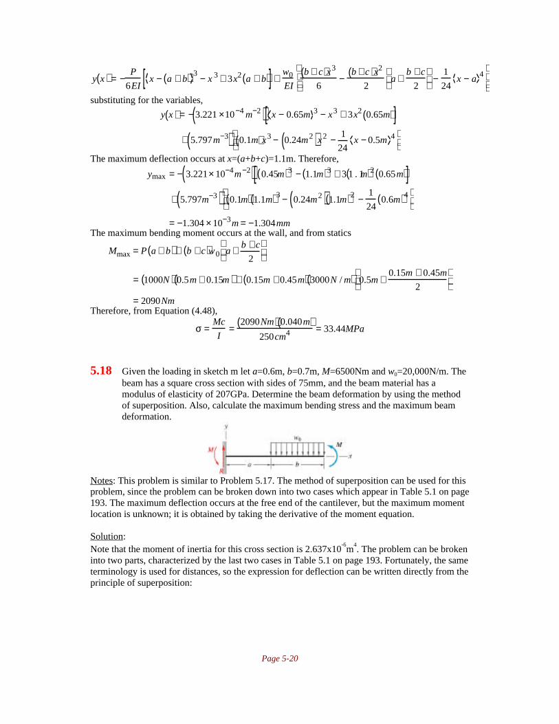
Page 5-20
y x( ) = −P
6EIx − a + b( ) 3 − x 3 + 3x2 a + b( )[ ] +
w0
EI
b + c( )x3
6−
b + c( )x2
2a +
b + c
2
−
1
24x − a 4
substituting for the variables,
y x( ) = − 3.221 ×10⁻⁴ m−2( ) x − 0.65m 3 − x3 + 3x2 0.65m( )[ ]+ 5.797m−3( ) 0.1m( )x3 − 0.24m2( )x2 − 1
24x − 0.5m 4
The maximum deflection occurs at x=(a+b+c)=1.1m. Therefore,
ymax = − 3.221× 10⁻⁴m−2( ) 0.45m( )3 − 1.1m( )3 + 3 1 . 1m( )2 0.65m( )[ ]+ 5.797m−3( ) 0.1m( ) 1.1m( )3 − 0.24m2( ) 1.1m( )2 −
1
240.6m( )4
= −1.304 × 10⁻³m = −1.304mmThe maximum bending moment occurs at the wall, and from statics
Mmax = P a + b( )+ b + c( )w0 a + b + c
2
= 1000N( ) 0.5m + 0.15m( ) + 0.15m + 0.45m( ) 3000N / m( ) 0.5m +0.15m + 0.45m
2
= 2090NmTherefore, from Equation (4.48),
σ =Mc
I=
2090Nm( ) 0.040m( )250cm4 = 33.44MPa
5.18 Given the loading in sketch m let a=0.6m, b=0.7m, M=6500Nm and w0=20,000N/m. Thebeam has a square cross section with sides of 75mm, and the beam material has amodulus of elasticity of 207GPa. Determine the beam deformation by using the methodof superposition. Also, calculate the maximum bending stress and the maximum beamdeformation.
Notes: This problem is similar to Problem 5.17. The method of superposition can be used for thisproblem, since the problem can be broken down into two cases which appear in Table 5.1 on page193. The maximum deflection occurs at the free end of the cantilever, but the maximum momentlocation is unknown; it is obtained by taking the derivative of the moment equation.
Solution:Note that the moment of inertia for this cross section is 2.637x10
-6m
4. The problem can be broken
into two parts, characterized by the last two cases in Table 5.1 on page 193. Fortunately, the sameterminology is used for distances, so the expression for deflection can be written directly from theprinciple of superposition:

Page 5-21
y =w0
EI
bx3
6−
bx2
2a +
b
2
−
1
24x − a 4
+
Mx2
2 EI
=20kN / m( )
207GPa( ) 2.637 ×10⁻⁶m4( ) 0.1167m( )x 3 − 0.3325m2( )x2 −1
24x − 0.6m 4
+
6500Nm
2 207GPa( ) 2.637 × 10⁻⁶ m4( ) x2
= 0.004275m−2( )x3 − 0.00623m −1( )x2 − 0.001527m−3( ) x − 0.6m 4
The location of the maximum value is determined by setting the derivative equal to zero andsolving for x. We do this over two intervals because of the presence of a singularity function atx=0.6m. Therefore, for x<0.6m,
dy
dx= 3 0.004275m−2( )x2 − 2 0.00623m−1( )x = 0
This requires that x=0 or x=0.972m. At x=0, y=0 because it is a fixed support. x=0.972m isoutside the range considered for the form of dy/dx. Therefore, there is no local minimum over thisrange, and the deflection at the edge of the interval is y=0. Over the range 0.6m<x<1.3m,
dy
dx= 3 0.004275m−2( )x2 − 2 0.00623m−1( )x − 4 0.001527m−3( ) x − 0.6m( )3 = 0
This has roots of x=0 and x=1.002m. x=0 lies outside the bounds for which the equation for dy/dxis valid. The deflection for x=1.002m is y=-0.001994m. At the end of the beam, y=-0.001503m.Therefore, the maximum deflection is y=-0.001994m=-1.994mm.
The maximum moment location is unknown. From Equation (5.3),
M = −EI( )d 2y
dx 2
Therefore, Mmax will occur where the third derivative of y with respect to x equals zero. The first,second and third derivatives of y(x) are:
dy
dx= 0.01283m−2( )x2 − 0.01246m−1( )x − 0.006108m−3( ) x − 0.6m 3
d2y
dx 2 = 0.02566m−2( )x − 0.01246m−1( ) − 0.018324m−3( ) x − 0.6m 2
d3y
dx 3 = 0.02566m−2( ) − 0.03665m−3( ) x − 0.6m
Setting the last equation equal to zero yields x=1.3m. The moment is then a maximum either atx=1.3 or at x=0, the other end of the beam. At x=1.3m, M=6500Nm. At x=0, M=6800Nm.Therefore, Mmax=6800Nm. The maximum bending stress is, from Equation (4.48),
σ =Mc
I=
6800Nm( ) 0.075m
2
2.637 × 10⁻⁶ m4 = 96.71MPa
5.19 The cantilevered beam shown in sketch n has both a concentrated force and a momentacting on it. Let a=1m, b=0.7m, P=8700N, and M=4000Nm. The beam cross section isrectangular with a height of 80mm and a width of 35mm. Also, E=207GPa. Calculate thebeam deflection by using the method of superposition. Find how large M has to be to givezero deflection at x=a.

Page 5-22
Notes: The problem is broken into two parts, one where only a load is applied at x=a, and onewith a moment applied at the end of the beam. The deflection for the beam is then the sum of thedeflections from the two cases by the principle of superposition. Table 5.1 is used to obtain thedeflections for the two cases.
Solution:The moment of inertia for the beam cross section is:
I =bh3
12=
0.035m( ) 0.080m( )3
12= 1.493× 10⁻⁶m4
Referring to Table 5.1 on page 193, the problem can be separated into a point load case at x=a(the first row in Table 5.1) and a moment applied at the free end (row 3 in Table 5.1). Therefore,from the method of superposition and recognizing the moment is opposite that shown in Table5.1, the deflection is:
y = − P
6 EIx − a 3 − x 3 + 3x2a[ ]+ Mx2
2EI
= −8700N( )
6 207GPa( ) 1.493 × 10⁻⁶ m4( ) x −1m 3 − x 3 + 3x2 1m( )[ ]+4000Nm
2 207GPa( ) 1.493 ×10⁻⁶m4( ) x2
= −0.00469m−2 x −1m 3 − x3 + 3m( )x2[ ] + 0.00647m−2( )x2
Note that if M is unknown, the deflection at x=a is given by:
y x = a( )= −P
6EI−a3 + 3a3[ ] +
Ma2
2EI;
Ma2
2EI=
2a3P
6EI; M =
2
3Pa =
2
38700N( ) 1m( ) = 5800Nm
5.20 A simply supported beam has loads as shown in sketch o. Calculate the beamdeformation by using the method of superposition. Also, calculate the maximum bendingstress and the maximum beam deformation and their locations. Assume that E=207GPaand that the beam has a rectangular cross section with a height of 30mm and a width of100mm. Also, P=1200N, w0=10,000N/m, a=0.2m, b=0.1m, c=0.4m, and d=0.2m.
Notes: This problem can be broken into the two cases given in Table 5.1(b). The approach is thesame as in Problem 5.19, but the relations for the deflection are slightly more complicated.
Solution:The moment of inertia for the beam is
I =bh3
12=
0.100m( ) 0.030m( )312
= 2.25 × 10⁻⁷m4
So that EI=46.57kNm2. Note that this problem can be broken into the case of a point load and a
distributed load, and the two cases combined through the method of superposition. The two casesare given in Table 5.1 (b) on page 193. Note that the variable labels in this problem statement donot correlate exactly with the nomenclature in Table 5.1(b), so care must be taken to use theproper expression. The deflection is:

Page 5-23
y = P
6EI
b + c + d
lx 3 − x − a 3 + 3a2x − 2alx − a3x
l
+ w0c
24lEI4 d + c
2
x 3 − l
cx − a − b 4 − x − a − b − c 4[ ] + x c3 + 6cd2 + 4c2d + 4d 3 − 4 l2 d + c
2
Substituting the given values,
y = 1200N( )6 46.57kNm2( )
0.7
0.9x 3 − x − 0.2m 3 + 3 0.2m( )2x − 2 0.2m( ) 0.9m( )x − 0.2m( )3 x
0.9m
+10kN / m( ) 0.4m( )
24 0.9m( ) 46.57kNm2( ) 4 0.4m( ) x 3 −0.9
0.4x − 0.3m 4 − x − 0.7m 4[ ]+ x −0.976m 3[ ]
= 0.00970m−2 x 3 − 0.004294m−2 x − 0.2m 3 − 0.004949x − 0.008946m−3 x − 0.3m 4 − x − 0.7m 4[ ]To find the position of maximum deflection, set dy/dx=0 and solve for x:dy
dx= 0.0291m−2 x 2 − 0.01288m−2 x − 0.2m 2 − 0.004949 − 0.03578m−3 x − 0.3m 3 − x − 0.7m 3[ ]
For 0<x<0.2, this becomesdy
dx= 0 = 0.0291m−2 x( )2 − 0.004949; x = 0.41m
This is outside the interval considered, so there is no local minimum or maximum over 0<x<0.2.Over 0.2<x<0.3,
dy
dx= 0 = 0.0291m−2 x2 − 0.01288m−2 x − 0.2 m( )2 − 0.004949; x = 0.4429m
Again, there is no local minimum or maximum in the interval 0.2<x<0.3. For 0.3<x<0.7, dy/dxbecomes:
dy
dx= 0.0291m−2x2 − 0.01288m−2 x − 0.2m( )2 − 0.004949 − 0.03578m−3 x − 0.3m( )3
This is solved as x=0.449m. Evaluating the deflection equation at x=0.449m,
ymax = 0.00970m−2 0.449m( )3 − 0.004294m−2 0.249m( )3
−0.004949 0.449 m( ) − 0.008946m−3 0.149m( )4[ ]= −0.001415m = −1.415mm
The bending moment can be found by applying Equation (5.3), so that
−M
EI=
d2 y
dx2 = 0.0582m−2 x − 0.02576m−2 x − 0.2m − 0.10734m−3 x − 0.3m 2 − x − 0.7m 2[ ]The maximum value is found by taking a derivative with respect to x, setting equal to zero, andsolving for x:
d
dx
M
EI= 0.0582m−2 x 0 − 0.02576m−2 x − 0.2m 0 − 0.21468m−3 x − 0.3m 1 − x − 0.7m 1[ ]
or x=0.451m. The maximum moment is then:
− Mmax
EI= 0.0582m−2 0.451m( ) − 0.02576m−2 0.251m( ) − 0.10734m−3 0.151m( )2[ ]
Mmax = EI −0.01733m−1( ) = 46.57kNm2( ) −0.01733m−1( ) = −807Nm
The maximum bending stress is, therefore,
σ =Mc
I=
807Nm( ) 0.015m( )2.25 × 10⁻⁷m4 = 53.8MPa

Page 5-24
5.21 The beam shown in sketch p is fixed at both ends and center loaded with a force of2300N. The beam is 3.2m long and has a square tubular cross section with an outsidewidth of 130mm and a wall thickness of 10mm. The tube material is AISI 1080 high-carbon steel. Calculate the deformation at any point along the beam by using the methodof superposition.
Notes: Symmetry should be used to transform the problem to a 1.6m long cantilever where theslope is zero at the end of the cantilever. Then two cases can be taken from Table 5.1.
Solution:The moment of inertia for the tube is:
I =1
12bo
4 − bi4( ) =
1
120.13m( )4 − 0.11m( )4[ ] = 1.16 ×10⁻⁵m4
Applying symmetry, the beam can be taken as follows:
Note that one-half the load has been applied to the left half of the beam, and an unknown internalmoment exists at the mid-point of the beam, which becomes the end of the cantilever. ApplyingTable 5.1,
y = −P / 2( )6 EI
x −l
2
3
− x 3 +3x2l
2
−
M2 x2
2EI
Note that M2 cannot be determined from statics. However, the end slope of the cantilever must bezero to preserve symmetry. The slope of the cantilever is obtained by taking dy/dx:
dy
dx= −
P( )12EI
3 x −l
2
2
− 3x2 + 3xl
−
M2 x
EI
Since dy/dx=0 at x=l/2, we can solve for M2 as:
0 = −P( )
12EI−3
l
2
2
+ 3l
2
l
−
M2 l
2EI; M2 = −
Pl
8
Therefore, substituting into the expression for y over 0<x<l/2:
y = −P / 2( )6 EI
−x3 +3x2 l
2
+
Plx2
16EI= −
Px2 l
16EI1−
4x
3 l
5.22 Bar A shown in sketch 1 is a 13-mm diameter aluminum bar; bar B is an 8 mm diametersteel bar. The lower member is of uniform cross section and is assumed to be rigid. Findthe distance x if the lower member is to remain horizontal. Assume that the modulus ofelasticity for steel is three times that for aluminum.

Page 5-25
Notes: The problem is statically indeterminate. There are three unknowns, namely the force inmembers A and B and the distance x. The three equations which will be used to solve the problemare force equilibrium, moment equilibrium and a deflection requirement - that for the beam toremain horizontal, the deflection has to be the same at A and B.
Solution:The reactions have been sketched in red. Note that the cross sectional area of bar A is
AA = π4
d2 = π4
0.013m( )2 = 1.327 ×10⁻⁴m2
Similarly, the cross sectional area of bar B is 5.0265x10⁻⁵m
2. Moment equilibrium about point A
yields
MA = 0∑ = 0.3m( )W − PBx; x = 0.3m( )WPB
Vertical force equilibrium yields:F∑ = 0 = PA +PB − W ; PA = W − PB
From Equation (4.26), the deflections at A and B are, respectively:
δ A = PA lAA EA
; δB = PBlABEB
For the bar to remain horizontal, δA=δB. Also, it is given that EB=3EA, and substituting for theareas gives:
δ A = δB; PAl
AAEA= PB l
ABEB;
PAl
1.327 ×10⁻⁴ m2( )EA
= PB l
5.0265×10⁻⁵ m2( ) 3EA( )Solving for PA gives PA=0.8802PB. Substituting into the force equilibrium equation gives
PA = 0.8802PB = W − PB ; PB = W1.8802
Substituting into the moment equilibrium equation gives
x = 0.3m( )WPB
= 0.3m( )WW /1.8802( ) = 0.564m
5.23 An aluminum rod 3/4 in in diameter and 48 in long and a nickel steel rod 1/2 in indiameter and 32 in long are spaced 60 in apart and fastened to a horizontal beam thatcarries a 2000 lbf load, as shown in sketch r. The beam is to remain horizontal after loadis applied. Assume that the beam is weightless and absolutely rigid. Find the location x ofthe load and determine the stresses in each rod.

Page 5-26
Notes: The approach is the same as Problem 5.22. The problem is statically indeterminate. Thereare three unknowns, namely the force in members A and B and the location of the applied forceW. The three equations which will be used to solve the problem are force equilibrium, momentequilibrium and a deflection requirement - that for the beam to remain horizontal, the deflectionhas to be the same at A and B.
Solution:From the inside front cover, the stiffness of aluminum is EA=10Mpsi, and the stiffness of steel is30Mpsi. The reactions have been sketched in red. Note that the cross sectional area of bar A is
AA = π4
d2 = π4
0.75in( )2 = 0.4418in2
Similarly, the cross sectional area of bar B is 0.1963in2. Moment equilibrium about point A yields
MA = 0∑ = x 2000lb( ) − PB 60in( ); x = 60in( )PB
2000lbVertical force equilibrium yields:
F∑ = 0 = PA +PB − 2000lb ; PA = 2000lb − PBFrom Equation (4.26), the deflections at A and B are, respectively:
δ A = PALA
AA EA; δB = PBLB
ABEBFor the bar to remain horizontal, δA=δB. Also, substituting for the lengths, areas, and elasticmoduli:
δ A = δB; PALA
AAE A= PBLB
AB EB;
PA 48in( )0.4418in2( ) 10Mpsi( )
= PB 32 in( )0.1963in2( ) 30Mpsi( )
Solving for PA gives PA=0.500PB. Substituting into the force equilibrium equation gives
PA = 2000lb − PB = 0.500PB ; PB =2000lb
1.500= 1333lb
Therefore, PA=0.516PB=680lb. Substituting into the moment equilibrium equation gives
x =60in( ) 1333lb( )
2000lb= 40.0 in
The stresses are obtained from Equation (4.22):
σA =PA
AA=
667lb
0.4418in2 =1510 psi
σB =PB
AB=
1333lb
0.1963in2 = 6741psi

Page 5-27
5.24 Find the force on each of the vertical bars shown in sketch s. The weight is assumed to berigid and horizontal, implying that the three vertical bars are connected at the weight in astraight line. Also, assume that the support at the top of the bars is rigid. The barmaterials and its circular cross-sectional area are given in the sketch.
Notes: This is a statically indeterminate problem. Fortunately, symmetry greatly simplifies thestatics. Just as in Problems 5.22 and 5.23, an equation based on deformations is used to obtain asolution.
Solution:From the inside front cover, Es=30Mpsi and Eb=16Mpsi. The internal forces in the bars are shownin the sketch in red. Note that symmetry has been applied, so that the steel bars bear the sameload. Vertical force equilibrium on the weight gives:
ΣF=0=2Ps+Pb-5000lb; 2Ps+Pb=5000lbFrom Equation (4.26), the deflections are:
δs = Ps LAsEs
; δb = PbLAbEb
Because of symmetry, the deflection of the steel and bronze must be equal. Also, substituting forthe lengths, areas, and elastic moduli:
δs = δ b; PsL
As Es= Pb L
AbEb;
Ps 36in( )0.2in2( ) 30Mpsi( )
= Pb 36in( )0.3in2( ) 16Mpsi( )
; Ps = 1.25Pb
Substituting into the force equilibrium equation:2 1.25Pb( ) + Pb = 5000lb; Pb =1430lb
Therefore, Ps=1.25Pb=1785lb.
5.25 Two solid spheres, one made of aluminum alloy 2014 and the other made of AISI 1040medium-carbon steel, are lowered to the bottom of the sea at a depth of 8000 m. Bothspheres have a diameter of 0.3m. Calculate the elastic energy stored in the two sphereswhen they are at the bottom of the sea if the density of water is 1000 kg/m
3 and the
acceleration of gravity is 9.807m/s2. Also calculate how large the steel sphere has to be to
have the same elastic energy as the 0.3m aluminum sphere.
Notes: The hydrostatic stress state which is applied is σ1=σ2=σ3=-p. Equation (5.29) allowscalculation of the strain energy.
Solution:The volume of the spheres is:

Page 5-28
V = 43
πr3 = 43
π 0.13m( )3 = 0.0141m3
From the inside front cover, Eal=72GPa, νal=0.33, Es=207GPa, νs=0.3. Note that a pressure gives ahydrostatic stress state of σ1=σ2=σ3=-p, where p is the pressure. p is calculated as
p = ρgh = 1000kg / m3( ) 9.807m / s2( ) 8000m( ) = 78.44MPa
From Equation (5.29), the strain energy is:
U = 1
2Eσ1
2 + σ22 +σ3
2( ) − νE
σ1σ2 +σ2σ3 +σ 3σ1( )
dv
v∫
= 12E
3p2( ) − νE
3p2( )
dv
v∫ = 3Vp2
2E1− 2ν( )
Substituting the elastic constants for aluminum,
Ual = 3Vp2
2E1− 2ν( ) =
3 0 . 0 1 4 1m3( ) 78.44 MPa( )2 72GPa( ) 1− 2 0.33( )( ) = 616.4Nm
and for the steel,
Us = 3Vp2
2 E1− 2ν( ) =
3 0.0141m3( ) 78.44MPa( )2 207GPa( ) 1− 2 0.3( )( ) = 252.2Nm
For the steel sphere to have the same energy as the aluminum sphere, that is, 616.4Nm, thevolume would have to be:
Us = 3Vp2
2 E1− 2ν( ); V = 2Us E
3p2 1− 2ν( )= 2 616.4 Nm( ) 207GPa( )
3 78.44MPa( )2 1− 2 0.3( )( )= 0.0346m2
since V=4πr3/3, the radius would have to be 0.202m, so the diameter would need to be 0.404m.
5.26 Use Castigliano’s approach instead of singularity functions to solve Problem 5.5. Assumethat transverse shear is negligible.
Notes: To find the deflection at a location where no load is applied, apply a fictitious load Q atthat point. From statics, determine the moment in each section, then energy is obtained fromEquation (5.19). Equation (5.30) is then used to obtain the deflection.
Solution:The reactions are shown in red, and a fictitious load Q is applied at the center of the beam wherethe deflection is desired. From symmetry the reaction forces are equal. Therefore, from verticalforce equilibrium,
F∑ = 0 = 2R −2 P− Q; R1 = R2 = Q2
+ P
Taking sections in the beam, and applying moment equilibrium, the bending moment in the beamis found at the various sections:
MAB = P + Q2
x
MBC = P + Q2
x − P x − a( ) = Qx
2+ Pa
MCD = P + Q2
x − P x − a( ) −Q x − l
2
= Q
l2
− x2
+ Pa

Page 5-29
MDE = − Qx2
+ Pa + Ql2
+ Q2
+ P
x − l + a( ) = Q
l2
− x2
+ P l − x( )
Note also from these expressions that∂MAB
∂Q= x
2∂MBC
∂Q= x
2∂MCD
∂Q= l
2− x
2
∂MDE
∂Q= l
2− x
2
From Equation (5.19), the strain energy is:
U = MAB2
2EIdx0
a∫ +MBC
2
2EIdx
al /2∫ +
MCD2
2EIdx
l / 2l−a∫ + MDE
2
2EIdx
l−al∫
The deflection at C in the direction of Q is given by Equation (5.30) as:
δ = ∂U∂Q
= MAB
EI∂MAB
∂Qdx0
a∫ +MBC
EI
∂MBC
∂Qdx
al /2∫ +
MCD
EI
∂MCD
∂Qdx
l / 2l−a∫ + MDE
EI∂MDE
∂Qdx
l−al∫
Substituting for the moments and their derivatives,
EIδ = P + Q
2
x2
2dx
0a∫ + Qx
2+ Pa
x
2dx
al /2∫ + Q
l
2− x
2
+ Pa
l
2− x
2
dx
l / 2l−a∫
+ Ql
2− x
2
+ P l − x( )
l
2− x
2
dx
l−al∫
Setting Q=0 yields
EIδ = P( ) x2
2dx0
a∫ + Pa( ) x2
dxal /2∫ + Pa( ) l
2− x
2
dx
l / 2l −a∫ + P l − x( )( ) l
2− x
2
dx
l−al∫
This is evaluated as
δ = PEI
a3
6+ a
4l2
4− a2
+
al2
l2
− a
− a
43l2
4− 2la + a2
+
16
l − l + a( )3
which can be reduced to
δ =aP 3l2 − 4a2( )
24EI
5.27 Using Castigliano’s theorem, find the maximum deflection of the two-dimensionalcantilevered bar shown in sketch t. Neglect transverse shear.
Notes: The strain energy for bending is calculated with Equation (5.19). Since M=Px, thenCastigliano’s theorem (Equation (5.30)) is used to obtain the deflection at the end of the bar,which is fortunately the location and in the direction of force application.

Page 5-30
Solution:From statics, the moment in the bar is M=Px. From Equation (5.19),
U = M2
2EIdx0
l∫ = P2 x2
2EIdx0
l∫From Equation (5.30),
y = ∂U∂P
= ∂∂P
P2 x2
2 EIdx0
l∫ = 2Px2
2EIdx0
l∫ = Px2
EIdx0
l∫The integral has to be broken into two parts because of the change in cross section, so that:
y = Px2
EIdx0
l /2∫ + Px2
2EIdx
l / 2l∫ = P
EI13
x3
0
l /2
+ P2EI
13
x3
l / 2
l
= 3Pl3
16EI
5.28 The right-angle-cantilevered bracket shown in sketch u is loaded with force P in the z-direction. Derive an expression for the deflection of the free end in the z-direction byusing Castigliano’s theorem. Neglect transverse shear effects.
Notes: The total strain energy is calculated from Equations (5.19) and (5.23). Equation (5.30) isthen used to obtain the desired deflection equation.
Solution:There are three sources of strain energy: bar ab is in bending, and bar bc is in bending andtorsion. For bar ab, the moment is Py, so equation (5.19) gives the strain energy as:
U1 = M2
2EIdy0
h∫ = P2 y2
2 EIdy0
h∫ = P2
2EI13
y3
0
h
= P2h3
6EIFor bar bc, the moment is M=Px (note the convenient definition of the coordinate system).Therefore, Equation (5.19) gives:
U2 = M2
2EIdx0
l∫ = P2 x2
2EIdx0
l∫ = P2
2EI13
x3
0
l
= P2 l3
6EIThere is a constant torque of T=Ph on bar bc, so that Equation (5.23) gives:
U3 = T2
2GJdx0
l∫ = P2h2
2GJdx0
l∫ = P2h2
2GJx( )0
l = P2h2 l2GJ
The total energy is then:
Utot = U1 + U2 +U3 = P2h3
6EI+ P2 l3
6EI+ P2h2 l
2GJFrom Castigliano’s theorem (Equation (5.30)),
δ = ∂U∂P
= ∂∂P
P2h3
6EI+ P2 l3
6EI+ P2h2 l
2GJ
=
Ph3
3EI+ Pl3
3EI+ Ph2l
GJ= P
3EIh3 + l3( ) + Ph2l
GJ

Page 5-31
5.29 A triangular cantilevered plate is shown in sketch v. Use Castigliano’s theorem to derivean expression for the deflection at the free end, assuming that transverse shear isneglected.
Notes: This problem is similar to Problems 5.26 through 5.28, except that the moment of inertiaof the cross section is a function of x. Once an expression is obtained for the moment of inertia,Equation (5.19) gives the strain energy and application of Equation (5.30) (Castigliano’sTheorem) gives the deflection equation.
Solution:The width of the plate varies as a linear function of x. At x=0, w=0. At x=l, w=b. Therefore, thewidth as a function of x is w=bx/l. The moment of inertia as a function of x is then:
I = wh3
12= 1
12bxl
h3 = bh3x
12 lThe moment as a function of x is M=Px. Therefore, Equation (5.19) gives:
U = M2
2EIdx0
l∫ = Px( )2
2Ebh3x12l
dx0l∫ = 6P2lx
Ebh3 dx0l∫ = 6P2l
Ebh312
x2
0
l
= 3P2l3
Ebh3
Applying Equation (5.30),
δ = ∂U∂P
= ∂∂P
3P2l3
Ebh3
=
6 Pl3
Ebh3
5.30 A right angle-cantilevered bracket withconcentrated load and torsional loading at the freeend is shown in sketch w. Using Castigliano’stheorem, find the deflection at the free end in the z-direction. Neglect transverse shear effects.
Notes: This problem is similar to Problem 5.28, butthe loading is slightly more complicated. The totalstrain energy is calculated from Equations (5.19)and (5.23). Equation (5.30) is then used to obtainthe desired deflection equation.

Page 5-32
Solution:From statics, the loading in the vertical section is a torque of Tv=T and a bending moment Mv=Py.For the horizontal section, the torque is Th=Pb, and the moment is Mh=Px+T. Using equations(5.19) and (5.23), the total strain energy is:
U = Mv2
2EIdy
0b∫ + Tv
2
2GJdy
0b∫ + Mh
2
2EIdx
0a∫ + Th
2
2GJdx
0a∫
=Py( )2
2EIdy0
b∫ + T2
2GJdy0
b∫ + Px + T( )2
2EIdx0
a∫ + Pb( )22GJ
dx0a∫
Applying Equation (5.30) (Castigliano’s theorem),
δ z = ∂U∂P
= ∂∂P
Py( )2
2EIdy0
b∫ + T 2
2GJdy0
b∫ + Px + T( )2
2EIdx0
a∫ + Pb( )2
2GJdx0
a∫
= 2Py2
2EIdy0
b∫ + 2 Px + T( )x2 EI
dx0a∫ + 2Pb2
2GJdx0
a∫ = PEI
13
y3
0
b
+ 1EI
Px3
3+ Tx2
2
0
a
+ Pb2
GJx( )0
a
= Pb3
3EI+ 1
EI
Pa3
3+ Ta2
2
+
Pb2a
2GJ=
P b3 + a3( )3EI
+ Ta2
2EI+ Pb2a
GJ
5.31 A cantilevered I-beam has a concentrated load applied to the free end as shown in sketchx. What upward force at point S is needed to reduce the deflection at S to zero? useCastigliano’s theorem. Transverse shear can be neglected.
Notes: The bending moment must be determined through statics over the two intervals. The totalstrain energy is then obtained through Equation (5.19) and Equation (5.30) is then used to obtainthe desired deflection equation.
Solution:Taking a section at x<200mm, the moment in this section is M=Px. For 200mm<x<500mm, themethod of sections gives M=Px-Sy(x-0.2m). Therefore, the strain energy is given be Equation(5.19) as:
U = M2
2EIdx
0l∫ = Px( )2
2EI00.2m∫ dx +
Px − Sy x − 0.2m( )( )2
2EIdx
0.2m0.5m∫
= Px( )22EI0
0.2m∫ dx +P − Sy( )x + Sy 0.2m( )( )2
2EIdx
0.2m0.5m∫
= P 2
2EI13
x3
0
0.2m+
P− Sy( )22EI
13
x3
0.2m
0.5m+
P − Sy( )Sy 0.2m( )EI
12
x2
0.2m
0.5m+
Sy 0.2m( )( )22EI
x( )0.2m0.5m
= P 2 0.2m( )36EI
+P− Sy( )2 0.5m( )3 − 0.2m( )3[ ]
6EI+
P− Sy( )Sy 0.2m( ) 0.5m( )2 − 0.2m( )2[ ]2EI
+Sy 0.2m( )( )2 0.3m( )
2EI

Page 5-33
Applying Equation (5.30), and recognizing the desired deflection is at location S,
δ = ∂U∂Sy
= ∂∂Sy
P2 0.2m( )3
6 EI+
P − Sy( )20.5m( )3 − 0.2m( )3[ ]
6EI+
P − Sy( )Sy 0.2m( ) 0.5m( )2 − 0.2m( )2[ ]2 EI
+Sy 0.2 m( )( )2
0.3m( )2EI
= −2 P − Sy( ) 0.5m( )3 − 0.2m( )3[ ]
6EI+
P − 2Sy( ) 0.2m( ) 0.5m( )2 − 0.2m( )2[ ]2EI
+Sy 0.2m( )2 0.3m( )
EISetting δ=0, and substituting P=5kN,
δ = 0 = −5kN − Sy( ) 0.117m3( )
3EI+
5kN − 2Sy( ) 0.042m3( )2 EI
+Sy 0.012m3
EI; Sy = 10kN
5.32 Using Castigliano’s theorem calculate the horizontal and vertical deflections at point Ashown in sketch y. Assume that E and A are constant.
Notes: This problem is similar to the previous problems, but transverse shear is not negligible.Therefore, the energy is calculated by combining axial, bending and transverse shear strainenergies. The equations are taken from Table 5.2 on page 200. Castigliano’s theorem (Equation(5.30)) is used to obtain the deflection.
Solution:The reactions have been drawn on the sketch in red. From statics, Rx=-Pcosθ=Px, Ry=Psinθ=Py,and M0=-Prcosθ-Prsinθ=-r(Px+Py). If a section is taken at any angle φ, the shear and normalforces can be determined as:
ΣFx=0=Rx+Vcosφ-FsinφΣFy=0=Ry-Vsinφ-Fcosφ
These equations are solved asF=Rycosφ+Rxsinφ=Pycosφ-PxsinφV=Rysinφ-Rxcosφ=Pysinφ+Pxcosφ
From Equation (2.5),
M = Vds∫ = Vrdφ∫ = Ry sinφ − Rx cosφ( )rdφ = r −Ry cosφ − Rx sinφ( ) + C∫The boundary condition is that M=M0 at φ=0, so that
M0 = r − Ry c o s 0− Rx s i n 0( ) + C; C = M0 + rRy
Therefore, the moment is
M = r −Ry cosφ − Rx sinφ( ) + M0 + rRy = M0 + r 1− cosφ( )Ry − Rx sinφ[ ]Referring to Table 5.2 on page 200, the total strain energy is:
U = M2rdφ2EI
+ F2rdφ2EA0
π /2∫ + 3V2rdφ5GA0
π /2∫0π / 2∫ = M2
2EI+ F2
2EA+ 3V 2
5GA
rdφ0
π / 2∫Therefore, the horizontal deflection is obtained by applying Equation (5.30):

Page 5-34
δx = ∂U∂Px
= ∂∂Px
M2
2EI+ F2
2EA+ 3V 2
5GA
rdφ0
π / 2∫ = M
EI∂M∂Px
+ FEA
∂F∂Px
+ 6V5GA
∂V∂Px
rdφ0
π / 2∫
= r3
EI0.5Py +0.356Px( ) + r
20AGEE 12Py +18.85Px( ) − G 10Py − 15.71Px( )[ ]
The vertical deflection is similarly calculated from Equation (5.30):
δy = ∂U∂Py
= ∂∂Py
M2
2EI+ F2
2EA+ 3V 2
5GA
rdφ0
π / 2∫ = M
EI∂M∂Py
+ FEA
∂F∂Py
+ 6V5GA
∂V∂Py
rdφ0
π / 2∫
= r3
4EIπPy + 2Px( ) + r
20AGEE 18.85Py +12Px( ) + G 15.71Py − 10Px( )[ ]
5.33 Calculate the deflection at the point of load application and in the loaddirection for a load applied as shown in sketch z. Assume that E and I areconstant.
Notes: This problem is similar to Problem 5.32, in that the strain energy is fairlycomplicated. Table 5.2 on page 200 gives the equations needed to calculate thestrain energy, and Castiglicano’s theorem (Equation (5.30)) gives the deflection.
Solution:From statics, the horizontal portion has a bending moment Mh=Px and a transverse shear Vh=P.the vertical portion has a bending moment Mv=Pl/4 and an axial force Pv=P. Therefore, using theproper equations in Table 5.2 on page 200, the strain energy is:
U = Mh2
2EIdx
0l / 4
∫ + 3Vh2
5GAdx + Pv
2
2EAdx
0l
∫ +0l /4
∫Mv
2
2 EIdx
0l
∫ = P2x2
2EIdx
0l /4
∫ + 3P 2
5GAdx + P2
2EAdx
0l∫ +
0l /4
∫P2 l2
8EIdx
0l∫
= P2
2EI13
x3
0
l /4+ 3P 2
5GAx( )0
l /4 + P2
2EAx( )0
l + P2 l2
8EIx( )0
l = 13P2 l3
384EI+ 3P2l
20GA+ P2 l
2EA
Therefore, from Equation (5.30),
δ = ∂U∂P
= ∂∂P
13P2 l3
384EI+ 3P2l
20GA+ P2 l
2EA
=
13Pl3
192EI+ 3Pl
10GA+ Pl
EA
5.34 Using Castigliano’s theorem, determine the horizontal and vertical deflections at point Aof sketch aa. Assume that E and I are constant.

Page 5-35
Notes: The sketch shows two links, not one structure. Once the loading on each link is determinedfrom statics, it can be shown that the problem reduces to that of Problem (5.32). This solutionuses the results from Problem (5.32) to obtain a solution.
Solution:The reactions have been drawn on the sketch in red. Note that the force P acting at A has its lineof action through the left support. Therefore, taking moment equilibrium about point 1:
ΣM=0From vertical force equilibrium,
ΣFy=0=R1y-Pcos45°; R1y=Pcos45°From horizontal force equilibrium,
ΣFx=0=R1x-Psin45°; R1x=Psin45°The right link has no load; obviously, there is no strain energy in the right link. Therefore, oneonly needs to consider the left link. Note that this then reduces to Problem 5.32, where φ=-45°,M0=0, and P=-P. Therefore, the deflections are, using the results from Equation (5.32),
δx = r3
EI0.5Py +0.356Px( ) + r
20AGEE 12Py +18.85Px( ) − G 10Py −15.71Px( )[ ]
The vertical deflection is similarly calculated from Equation (5.30):
δy = r3
4EIπPy + 2Px( ) + r
20AGEE 18.85Py +12Px( ) + G 15.71Py − 10Px( )[ ]
5.35 For the structure shown in sketch bb, find the force in each member and determine thedeflection at point A. Assume that E and A are the same in each member.
Notes: The forces in each member are obtained from statics, but in order to obtain the verticaldeflection at point A, include a load Q in the analysis as shown. The force in each member will beobtained by substituting Q=0, but this allows application of Castigliano’s theorem to obtain thevertical as well as horizontal deflection at A. Each member contains only an axial load, soEquation (5.18) gives the strain energy.
Solution:I. Geometry RelationsThe reactions have been added to the sketch in red. Note also the nomenclature for angles andlengths which have been added to the sketch. From geometry, note that β+2θ=π/2. This can berewritten as
β+θ=π/2-θ, or cos(β+θ)=cos(π/2-θ)=sinθAlso,
cosβ=cos(π/2-2θ)=sin(2θ)=2sinθcosθ

Page 5-36
and from the law of sines,a
sin θ= b
sinπ2
− β
;b = 2acosθ
II. Determination of ReactionsThe reactions are determined from statics. From moment equilibrium at point C,
M = 0∑ = 2Ba cosβ + P + Q( )acos β − Pbcos θ = 0
= B 2a sin2θ( )+ P +Q( )a sin2θ − P 2a cos2 θ( ) = 0; B = P2
cotθ − P2
− Q2
From horizontal force equilibrium, Cx=-P. From vertical force equilibrium,
Fy = 0∑ = Cy − B − P − Q; Cy = B + P +Q = P2
cotθ − P2
− Q2
+ P+ Q = P2
cotθ + P2
+ Q2
III. Determination of Member TensionsTaking a section at joint B gives the following free body diagram:
From horizontal force equilibrium,Fx = 0 = FAB cos β +θ( ) − FDB cos β ;∑
FAB = FDBcos β
cos β +θ( ) = FDB2 s i nθ cos θ
sinθ= 2FDB cosθ
From vertical force equilibrium,Fy∑ = 0 = −B − FDB sinβ + FAB sin θ + β( )
= −B − FDB sinβ + 2 FDB cosθ sin θ + β( )These yield
FDB =PH
2cot θ −
PV
2−
Q
2FAB=cosθ[(PHcotθ-PV)-Q]
Taking a section at Joint D gives:From horizontal force equilibrium,
ΣFx=0=FCD-FDB; FCD=FDB
From vertical force equilibrium,ΣFy=0=FCDsinβ+FDBsinβ-P-FAD
These yield
FCD = FDB =PH
2cotθ −
PV
2−
Q
2FAD = 2 FDB sin β − PV = cos2θ PH cotθ − PV − Q[ ] − PV
Taking a section at Joint A gives:From horizontal force equilibrium,
FACsinθ+FABsinθ-PH=0Therefore,
FAC =PH
sinθ− cosθ PH cotθ − PV − Q[ ]
The force in each member is obtained by substituting Q=0.
IV. Determination of Deflections

Page 5-37
The total strain energy is obtained by taking the sum of the individual energies. Since eachmember experiences only an axial load, Equation (5.17) is applied to each member. The totalstrain energy is
U = FAB2
2AEdx0
b∫ +FAC
2
2AEdx0
b∫ + FAD2
2AEdx0
a∫ + FBD2
2AEdx0
a∫ +FCD
2
2 AEdx0
a∫Applying Equation (5.30), the horizontal deflection is:
δx = ∂U∂P
= FAB
AE∂FAB
∂Pdx
0b∫ +
FAC
AE
∂FAC
∂Pdx
0b∫ + FAD
AE∂FAD
∂Pdx
0a∫ + FBD
AE∂FBD
∂Pdx
0a∫ +
FCD
AE
∂FCD
∂Pdx
0a∫
Substituting the following:∂FAB
∂PH= cosθ cotθ
∂FAC
∂PH=
1
sinθ− cosθ cotθ =
1
sinθ−
cos2 θsinθ
=1− cos2θ
sinθ= sinθ
∂FAD
∂PH= cos2θ cotθ
∂FBD
∂PH=
cotθ2
∂FCD
∂PH=
cotθ2
δx is then given by
δx = ∂U
∂PH= P
EAb( )cos θ cotθ −1( ) cosθ cot θ + b sinθ( ) 1
sinθ− cosθ cotθ − 1( )
+ac o s 2θ cot θ c o s 2θ cotθ − 1( ) −1( ) + 2acotθ − 1
2
cot θ2
or, simplifying,
δ x = P
EAb cotθ −1( )cos2θ cotθ +1 − cotθ − 1( ) cosθ sinθ( )[
+a cotθ − 1( )cos22θ cotθ − cos2θ cotθ + cotθ − 1( ) cotθ2
The vertical deflection at point A is:
δy = ∂U∂Q
= FAB
AE∂FAB
∂Qdx
0b∫ +
FAC
AE
∂FAC
∂Qdx
0b∫ + FAD
AE∂FAD
∂Qdx
0a∫ + FBD
AE∂FBD
∂Qdx
0a∫ +
FCD
AE
∂FCD
∂Qdx
0a∫
Substituting:∂FAB
∂PV= −1
∂FAC
∂PV= cosθ
∂FAD
∂PV= − cos2θ
∂FBD
∂PV= −
1
2∂FCD
∂PV= −
1
2

Page 5-38
gives an expression for δy as:
δy = ∂U
∂PV= bP
AEcosθ cotθ −1( ) −1( ) + 1
sinθ− cosθ cotθ − 1( )
cosθ
+ aP
AEcos2θ cotθ − 1{ } −1( ) 1− c o s 2θ( ) + cotθ −1
2
− 1
2
+
cotθ − 1
2
− 1
2
Simplifying,
δ y =∂U
∂PV=
bP
AE
1
sinθ+ cot θ sinθ − cosθ( ) 1 − cosθ( )
+ aP
AE
1
21− cotθ( ) + cos2θ −2 + c o s 2θ + cot2θ 1− cos2θ( ){ }
Page 6-1
Chapter 6 • Failure Prediction for Static Loading
6.1 Given that the stress concentration factor is 3.12 for a machine element made of steelwith a modulus of elasticity of 207GPa, find the stress concentration factor for anidentical machine element made of aluminum instead of steel. The modulus of elasticityfor aluminum is 69GPa.
Solution:Since the elastic stress concentration is entirely determined from the geometry of the machineelement, the stress concentration factor will remain the same. Therefore, Kc=3.12.
6.2 A flat part with constant thickness b is loaded in tension as shown in Fig. 6.3(a). Theheight changes from 50 to 100mm with a radius r=10mm. Find how much higher a loadcan be transmitted through the bar if the height increases from 50 to 70 mm and theradius decreases from 10 to 3mm.
Notes: To answer this question, one must compare the stress concentration factors for the twocases. The stress concentration factors are obtained from Figure 6.3(a) on page 233.
Solution:Referring to the sketch in Figure 6.3(a), H=100mm, h=50mm and r=10mm for the first case.Therefore, H/h=100mm/50mm=2 and r/h=10mm/50mm=0.2. From Figure 6.3(a), Kc for this caseis 1.8. For the second case, H/h=100/70=1.43 and r/h=3mm/70mm=0.043. Therefore, FromFigure 6.3(a), Kc is around 2.8.
The load that can be transmitted depends on the maximum stress. Therefore, for the firstcase:
σmax = Kc1P1
bh1; P1 = bh1σmax
Kc1= b 50mm( )σ max
1.8For the second case:
σmax = Kc 2P2
bh2; P2 =
bh2σmax
Kc2=
b 70mm( )σ max
2.8The ratio of the two forces is:
P1
P2=
b 50mm( )σ max
1.8
b 70mm( )σ max
2.8
= 50mm( )2.870mm( )1.8
= 1.111
Therefore the load carrying capacity decreases even though the thickness of the bar increasedfrom 50 to 70 mm, mainly because the radius of the notch decreased.
6.3 A flat steel plate is axially loaded as shown in sketch a has two holes for electric cables.The holes are situated beside each other and each has a diameter d. To make it possible todraw more cables, the holes are placed with one hole having twice the diameter 2d, asshown in sketch b. Assume that the ratio of diameter to width is d/b=0.2 for the two-holeplate. Which plate will fail first?

Page 6-2
Notes: The exact hole locations have not been specified, so some variation may occur withassumed dimensions. Also, the two-hole case does not correspond to a particular chart in Figure6.1 through 6.6. However, it is possible to obtain a reasonable solution from the existing data. Fora critical application, more advanced approaches, such as finite element analysis, would benecessary. See also Problem 6.6.
Solution:It will be assumed that the top and bottom halves of the plate are symmetric about the centerline,and that the holes are placed in the center of each half of the plate. The locations where the largeststress could occur are A and B in the sketch.
Considering the top half of the problem leads to:Here the diameter to width ratio is 0.4, so Kc isaround 2.2 from Figure 6.2(a). Note that this istrue for point A but not point B in the figureabove.
Because of St. Venant’s Principal, we must be concerned about the stress concentrationsinteracting between the two holes. For B, take a section through the hole diameters to yield:
Here H=b/2, h=b/2-d,r/h=(d/2)/(b/2-d)=0.1b/(0.5b-0.2b)=0.33.Therefore, Kc is just under 2.0 from Figure6.4(a).
Therefore, the larger stress concentration is Kc=2.2 and point A is more important than point B.For the single hole, Figure 6.2 (a) gives a stress concentration of Kc=2.2 (d/b=0.4). Therefore,either design is expected to fail at the same stress.
6.4 A load-carrying beam is loaded with a bending moment M. The minor beam height is hand the width in the perpendicular direction is b. This beam, which carries a balcony onthe wall of a house, is welded together with a beam in the house structure. That beam hasa major height H. Because of manufacturing problems the radius r of the connectionscannot be made larger than rmax but can be made smaller, down to zero. Find how theload-carrying beam should be placed on the house beam to give maximum strength.
Notes: Design recommendations arise from studying Figure 6.3 (b).
Solution:From Figure 6.3 (b), the stick-out H/h should be small to give a low stress concentration factor.Also, the radius to height ratio should be as large as possible. The optimum configuration is tohave the small beam flush with the top side of the large beam which gives zero stressconcentration.

Page 6-3
6.5 A round bar has a fillet with r/d=0.15 and D/d=1.5. The bar transmits both bendingmoment and torque. A new construction is considered to make the shaft stiffer andstronger by making it equally thick on each side of the fillet or groove. Determinewhether that is a good idea.
Notes: Figures 6.5 and 6.6 are used to obtain the solution.
Solution:For r/d=0.15 and D/d=1.5, the stress concentrations for bending is just over 1.5 for bending (fromFigure 6.5 (b)) and about 1.25 for torsion (from Figure 6.5(c)). If instead of a fillet the bar becamea groove, with the same root diameter, then the stress concentrations are obtained from Figure 6.6(b) and (c). The new stress concentration factors are around 1.65 for bending and 1.325 fortorsion. Since the stress concentration factors are higher for the proposed redesign, it is not a goodidea.
6.6 A rectangular plate has a central hole. The width of the plate is b=50mm and the diameterof the hole is d=10mm. The plate is axially loaded with a force P=1500N, and the minorheight of the plate is h=5mm. Is it possible to find the stress concentration factor for theplate without using Figure 6.2?
Notes: Figure 6.2 can obviously be used to solve the problem, and serves as a useful comparisonfor the alternate technique. The problem can be approximated by Figure 6.4 if the plate issectioned. This solution compares the results of both approaches.
Solution:First of all, if Figure 6.2(a) is used with d/b=(10mm)/(50mm)=0.2, Kc=2.5. An alternativeapproach is to cut the beam in half across the center of the hole, then reassembling the twosections so the holes are on the exterior, thereby approximating the loading case in Figure 6.4(a).Note that there are differences; there are not two matching fillets on opposite sides, and theloading is complicated by the presence of a Poisson effect in the original geometry. However, thetwo should be fairly close. For the new, sectioned geometry, r=d/2=5mm, H=b=50mm, h=(b-d)=(50mm-10mm)=40mm. Therefore, H/h=(50mm)/(40mm)=1.25, andr/h=(5mm)/(40mm)=0.125. From Figure 6.4(a), Kc is around 2.3. The error between the two casesis:
%error =2.5 − 2.3
2.5×100% = 8%
6.7 A machine has three circular shafts, each with fillets giving stress concentrations. Theratio of fillet radius to shaft diameter is 0.1 for all three shafts. One of the shafts transmitsa tensile force, one transmits a bending torque, and one transmits torsion. Because theyare stressed exactly to the stress limit (ns=1), a design change is proposed doubling thenotch radii to get a safety factor greater than 1. How large will the safety factors be forthe three shafts if the diameter ratio is 2 (D/d=2)?
Notes: Figure 6.5 is used to solve this problem.

Page 6-4
Solution:For the shaft under tension, Figure 6.5(a) is used to obtain the stress concentration
factors. For D/d=2 and r/d=0.1, Kc=2.0, and corresponds to the original case. If r is doubled, thenr/d=0.2 and Kc=1.65. Since the original design was fully stressed, the new safety factor is
ns =2
1.65= 1.21
For the shaft under bending, Figure 6.5(b) is used to obtain the stress concentrationfactors. For D/d=2 and r/d=0.1, Kc=1.7, and corresponds to the original case. If r is doubled, thenr/d=0.2 and Kc=1.43. Since the original design was fully stressed, the new safety factor is
ns =1.7
1.43= 1.19
For the shaft under torsion, Figure 6.5(c) is used to obtain the stress concentration factors.For D/d=2 and r/d=0.1, Kc=1.43, and corresponds to the original case. If r is doubled, thenr/d=0.2 and Kc=1.22. Since the original design was fully stressed, the new safety factor is
ns =1.43
1.33= 1.17
Therefore, the lowest safety factor is ns=1.17 and corresponds to the torsion-loaded shaft.
6.8 The shaft shown in sketch c is subjected to tensile, torsional, and bending loads.Determine the principal stresses at the location of stress concentration.
Notes: This problem can be easily solved through the principal of superposition. The stressconcentration factors are obtained from Figures 6.5 (a) and (b).
Solution:The rod will see normal stresses due to axial loads and bending, and a shear stress due to torsion.Note that the shear stress due to shear is zero at the extreme fibers where the stresses are largest.The critical location is at the bottom where the bending and axial stresses are both tensile. Assignthe x-axis to the rod axis. The normal stress is given by:
σx = Kc1P
A+ Kc2
Mc
I= 2.0( ) 10kN
π4
0.03m( )2+ 1.75( ) 50kN( ) 0.130m( ) 0.015m( )
π64
0.030m( )4= 4315MPa
where the stress concentration factors of 2.0 and 1.75 are obtained from Figure 6.5 (a) and (b).The shear stress is
τ = KcTc
J= 1.45( ) 100Nm( ) 0.015m( )
π32
0.030m( )4= 27.4MPa
Equation (2.16) gives the principal stresses.
σ1,σ2 =σx + σ y
2± τxy
2 +σx − σy
2
2
=4315MPa
2± 27.4MPa( )2 +
4315MPa
2
2

Page 6-5
or σ1=4315MPa and σ2=-0.17MPa. Note that the shear stress is very small compared to thenormal stress; we could have taken σx as a principal direction.
6.9 A steel plate with dimensions shown in sketch d is subjected to a 150kN tensile force and300Nm bending moment. The plate is made of AISI 1080 steel and is kept at 20°C. Ahole is to be punched in the center of the plate. What is the maximum diameter of thehole for a safety factor of 1.5?
Notes: Equation (3.16) gives the allowable stress in bending. The normal stress is the sum of thebending stress and the axial normal stress, and is equated to the allowable stress. This gives anequation in terms of the hole diameter and the stress concentration factors in tension and bendingwhich can be solved iteratively.
Solution:From the inside front cover, AISI steel has a yield strength of Sy=380MPa. Therefore, theallowable stress is given by Equation (3.16) as:
σall=0.6Sy=0.6(380MPa)=228MPaHowever, since the safety factor is 1.5, the allowable stress for this problem is 228MPa/1.5=152MPa. The stress associated with axial tension is (see Figure 6.2(a)):
σa =Kca P
b − d( )h=
Kca 150kN( )0.235m − d( ) 0.025m( )
=6MN / m
0.235m − dKca
The stress associated with bending is (see Figure 6.2(b)):
σb =6KcbM
b − d( )h2 =6Kcb 300Nm( )
0.235m − d( ) 0.025m( )2 =2.88MN / m
0.235m −dKcb
Therefore, the maximum stress is:
σmax = σa + σb =6MN / m( )Kca + 2.88MN /m( )Kcb
0.235m − dThis should be equated to the maximum allowable stress, of σmax=152MPa. Note that Kca and Kcb
are functions of only d, since the other variables needed for their definition are fixed. Therefore,this equation can be iteratively solved. Note that we can re-write the equation as:
6MN / m( )Kca + 2.88MN / m( )Kcb
0.235m − d= 152MPa; d = 0.235m −
6MN / m( )Kca + 2.88MN / m( )Kcb
152MPaAssume d=100mm, so that d/b=(100mm)/(235mm)=0.426, and d/h=100/25=4. From
Figure 6.2 (a), Kca=2.2 and From Figure 6.2 (b), Kcb=1.46. Therefore, this equation would predict
d = 0.235m −6MN / m( ) 2.2( ) + 2.88MN /m( ) 1.46( )
152MPa= 0.120m
Therefore, the initial value was too small. If we now use d=0.120m=120mm, thend/h=120/25=4.8 and d/b=120/235=0.511. This gives Kca=2.16 and Kcb=1.4. Therefore,
d = 0.235m −6MN / m( ) 2.16( ) + 2.88MN / m( ) 1.4( )
152MPa= 0.123m
This is close to the assumed value, and closer agreement between assumed and calculated valuesis difficult because of the resolution of Figures 6.2(a) and 6.2(b).

Page 6-6
6.10 A Plexiglass plate with dimensions 1m x 1m x 1cm is loaded by a nominal tensile stressof 55MPa in one direction. The plate contains a small crack perpendicular to the loaddirection. At this stress level a safety factor of 1.3 against crack propagation is obtained.Find how much larger the crack can get before it grows catastrophically.
Notes: Equation (6.4) is used to solve this problem.
Solution:For the first case, Equation (6.4) gives:
Kci
1.3= Yσnom πa1 ; Kci = 1.3Yσnom πa1
For the second case, the safety factor would be unity so that:Kci = Yσnom πa2
Substituting for Kci:
Yσnom πa2 = 1.3Yσnom πa1 ; a2 = 1.32a1 = 1.69a1Therefore, the crack can be 69% larger before catastrophic failure occurs.
6.11 A pressure container is made of AISI 4340 steel. The wall thickness is such that thetensile stress in the material is 1100MPa. The dimensionless geometry correction factorY=1 for the given geometry. Find how big the largest crack can be without failure if thesteel is tempereda) at 260°Cb) at 425°C
Notes: The material properties as a function of temper temperature is obtained from Table 6.1.Equation 6.4 is used to solve the problem.
Solution:The nominal stress is given as σnom=1100MPa, and Y=1. The critical crack length is derived fromEq. (6.4):
Kci = Yσnom πa;a =1
πKci
Yσnom
2
From Table 6.1, at a temper of 260°C, the fracture toughness is 50MPam1/2. Therefore, thecritical crack length is 1.3 mm. At a temper of 425°C, The critical crack length is 4.0mm. (Note:a is one-half the crack length.)
6.12 Two tensile test rods are made of AISI 4340 steel tempered at 260°C and aluminum alloy2024-T351. The dimensionless geometry correction factor Y=1. Find how high a stresseach rod can sustain if there is a 2-mm crack half length in each of them.
Notes: The fracture toughness for these materials is obtained from Table 6.1 on page 232. Thenominal stress that can be sustained is then given by Equation (6.4).
Solution:

Page 6-7
From Table 6.1 on page 232, Kci for AISI 4340 is 50.0MPam1/2
. For Al 2024-T351, Kci is36MPam
1/2. Therefore, the stress in the steel is given by Equation (6.4) as:
Kci = Yσnom πa;σnom =Kci
Y πa=
50.0MPa
1( ) π 0.002( )= 631MPa
For the Al 2024-T351,
Kci = Yσnom πa;σnom =Kci
Y πa=
36.0 MPa
1( ) π 0.002( )= 454MPa
6.13 A plate made of titanium alloy Ti-6Al-4V has the dimensionless correction factor Y=1.How large can the largest crack in the material be if it still should be possible toplastically deform the plate in tension?
Notes: To plastically deform the plate, the nominal stress must exceed the yield strength of thematerial. Therefore, Equation (6.4) solves the problem.
Solution:From Table 6.1 on page 232, the fracture toughness for Ti-6Al-4V varies from 44-66 MPam
1/2.
Also, the yield strength is 910MPa. To plastically deform the material, σnom>Sy, or, from Equation(6.4),
Kci = Yσnom πa; σnom =Kci
Y πa≥ Sy
Solving for a,
Kci
Y πa≥ Sy ; a =
1
πKci
YSy
2
=1
πKci
1( ) 910 MPa( )
2
Since Kci has a value between 44-66MPam1/2
, then a has a range of a≤0.744-1.67mm. Therefore,if the largest crack is below 0.744mm in half-length (1.488mm in length), then the nominal stresswill be larger than the yield strength.
6.14 A plexiglass model of a gear has a 1-mm crack half-length formed in its fillet curve(where the tensile stress is maximum). The model is loaded until the crack starts topropagate. Y=1.5. How much higher a load can a gear made of AISI 4340 steel temperedto 425°C carry with the same crack and the same geometry?
Notes: Equation (6.4) is used to solve the problem with data from Table 6.1. This solution makessure that the steel does not plastically deform before catastrophic crack propagation occurs.
Solution:From Table 6.1 on page 232, the fracture toughnesses for plexiglass and steel are 1.0 and 87.4MPam
1/2, respectively. For a gear, the bending stress is directly proportional to the applied load,
so for a constant crack size a and correction factor Y the load possible is directly proportional toKci. Therefore, Kci for steel is 87.4 times larger than for plexiglass, so it may be possible tosupport a load 87.4 times larger.
However, it is possible that the steel will plastically deform at a lower stress than thatneeded to propogate the crack. With a=1mm=0.001m, Equation (6.4) predicts the nominal stresslevel as:

Page 6-8
Kci = Yσnom πa; σnom =Kci
Y πa=
87.4MPa m
1.5( ) π 0.001m( )=1040MPa
Table 6.1 gives the yield strength for AISI 4340 tempered to 425°C as 1420MPa. Therefore, thenominal stress level needed for crack propagation is not sufficient to cause plastic deformation,and a load 87.4 times larger than for plexiglass can be carried.
6.15 A pressure container made of aluminum alloy 2024-T351 is manufactured for a safetyfactor of 2 guarding against yielding. The material contains cracks through the wallthickness with a crack half-length less than 3mm. Y=1. Find the safety factor whenconsidering crack propagation.
Notes: The safety factor guarding against crack propagation is obtained from the ratio of thefracture toughness of the material to the stress intensity factor calculated by Equation (6.4).
Solution:From Table 6.1 on page 232, Sy=325MPa and Kci=36MPa-m
1/2. The safety factor guarding against
yielding is 2, therefore the nominal stress is one-half the yield strength, or σnom=162.5MPa. Thestress intensity factor is therefore calculated from Equation (6.4) as
Ki = Yσnom πa = 1( ) 162.5MPa( ) π 0.003m( ) =15.78MPa mThe safety factor against crack propagation is therefore
ns = Kci
Ki= 36MPa m
15.78MPa m= 2.28
Since the safety factor for yielding is lower than the safety factor guarding against crackpropagation, the safety factor for the pressure vessel is still 2.
6.16 The clamping screws holding the top lid of a nuclear reactor are made of AISI 4340 steeltempered at 260°C. They are stressed to a maximum level of 1250MPa during apressurization test before starting the reactor. Find the safety factor guarding againstyielding and the safety factor guarding against crack propagation if the initial cracks inthe material have Y=1 and a=1mm. Also, do the calculations for the same material buttempered to 425°C.
Notes: This problem is similar to the previous problem. Equation (6.4) is used to solve thisproblem.
Solution:I. AISI 4340 Tempered at 260°CFrom Table 6.1 on page 232, Sy=1640MPa and Kci=50MPa-m
1/2. The safety factor against
yielding is therefore
ns =Sy
σ=
1640MPa
1250MPa= 1.31
From Equation (6.4), the stress intensity factor is
Ki = Yσ nom πa = 1( ) 1250MPa( ) π 0.001m( ) = 70.06 MPa mThe safety factor guarding against crack propagation is therefore

Page 6-9
ns = Kci
Ki= 50MPa m
70.06MPa m= 0.714
Since the safety factor is less than 1, the bolts will fail.II. AISI 4340 Tempered at 435°CFrom Table 6.1 on page 232, Sy=1420MPa and Kci=87.4MPa-m
1/2. Using the same equations, the
safety factor against yielding is ns=1.14, and the safety factor against crack propagation isns=1.25. Therefore, the bolts will not crack.
6.17 A glass tube used in a pressure vessel is made of aluminum oxide (sapphire) to make itpossible to apply 30MPa pressure and still have a safety factor of 2 guarding againstfracture. For a soda-lime glass of the same geometry only 7.5 MPa pressure can beallowed if a safety factor of 2 is to be maintained. Find the size of the cracks the glasstube can tolerate at 7.5MPa pressure and a safety factor of 2. Y=1 for both cases.
Notes: Material properties are obtained from Table A.3. As is shown in Chapter 9, the stress isproportional to the pressure. Equation (6.4) is used to solve this problem.
Solution:From Table A.3 on page 901, the fracture strength of soda-lime glass is 69MPa. The stresses inthe tube are directly proportional to the pressure, so the fracture strength of the aluminum oxidetube is:
S fa
pa=
Sfs
ps;S fa =
S fs pa
ps= 69MPa( ) 30MPa( )
7.5MPa= 276MPa
Note that this is on the low end of the fracture strength values given in Table A.3 for aluminumoxide (Al2O3).
For a safety factor of 2, the applied stress is 276/2=138MPa. From Table 6.1 on page232, using a low value of fracture toughness for Al2O3, use Kcia=3.0MPa-m
1/2. From Equation
(6.4),
Ki = Kci
2= Yσnom πa ; a = 1
πKci
2Yσnom
2
= 1π
3.0MPa m2 1( ) 138MPa( )
2
= 3.76 ×10⁻⁷ m = 37.6µm
For the soda lime glass, the lowest value of fracture toughness is Kci=0.7MPa-m1/2
. The appliedstress is σnom=69MPa/2=34.5MPa. The stress intensity factor is
Ki = Kci
2= Yσnom πa ; a = 1
πKci
2Yσnom
2
= 1π
0.7MPa m2 1( ) 34.5MPa( )
2
= 3.28×10⁻⁷m = 32.8µm
Therefore, the largest crack in the aluminum oxide must be less than 2a or 75.2µm, while forsoda lime glass the largest crack must be smaller than 65.6µm.
6.18 A stress optic model used for demonstrating the stress concentrations at the ends of acrack is made of polymethylmethacrylate. An artificially made crack 100mm long isperpendicular to the loading direction. Y=1. Calculate the highest tensile stress that can beapplied to the model without propagating the crack.
Notes: Material properties are obtained from Table 6.1 and Table A-4. Equation (6.4) is used tosolve this problem.

Page 6-10
Solution:From Table 6.1 on page 232, the critical stress intensity factor for polymethylmethacrylate isKci=1.0MPa-m
1/2. From Equation (6.4) the stress when the crack propagates catastrophically is:
Kci = Yσnom πa; σ nom =Kci
Y πa=
1.0MPa m
1( ) π 0.1m( )= 1.78MPa
From Table A-4 on page 902, the ultimate strength is between 48 and 76 MPa. Therefore, thecrack will propagate at a stress far lower than the ultimate strength of the material.
6.19 A passengerless airplane requires wings that are lightweight and the prevention of cracksmore than 2mm long. The dimensionless geometry correction factor Y is usually 1.5 for asafety factor of 2. What is the appropriate alloy for this application? If Y is increased to4.5, what kind of alloy from Table 6.1 should be used?
Notes: Equation (6.4), combined with material properties from Table 6.1, allow solution of thisproblem.
Solution:To maintain a safety factor of 2, set σnom=Sy/2. Therefore, Equation (6.4) gives:
Kci = Yσnom πa = 1.5( )Sy
2π 0.002m( ) = 0.0594 m( )Sy
From Table 6.1 on page 232, the following data is obtained:Material Kci/Sy (m
1/2)
Aluminum alloy, 2020-T351Aluminum alloy, 7075-T651
Alloy steel 4340, tempered at 260°CAlloy steel 4340, tempered at 425°C
Titanium alloy Ti-6Al-4V
0.1110.05740.03050.06150.0483
Therefore, either Aluminum alloy 2020-T351 or Alloy steel 4340 tempered at 425°C would work.For weight savings, the aluminum alloy is probably the better choice.
If Y=4.5, Equation (6.4) gives:
Kci = Yσnom πa = 4.5( )Sy
2π 0.002m( ) = 0.178 m( )Sy
None of the materials in Table 6.1 would be acceptable for this case.
6.20 The anchoring of the cables carrying a suspension bridge are made of cylindrical AISI1080 steel bars 210mm in diameter. The force transmitted from the cable to the steel baris 3.5 MN. Calculate the safety factor range guarding against yielding.
Notes: The material property is obtained from the inside front cover. Equation (3.13) gives arange for allowable stresses in tension.
Solution:From the inside front cover, the yield strength for AISI 1080 is Sy=380MPa. The stress in the steelbar is

Page 6-11
σ =P
A=
3.5MNπ4
0.21m( )2= 101MPa
Since the safety factor is ns=σall/σ, Equation (3.13) gives
0.45Sy ≤ σall ≤ 0.60Sy ; 0.45 Sy
σ≤ ns ≤
0.60Sy
σ;
0.45 380MPa( )101MPa
≤ ns ≤0.60 380MPa( )
101MPaTherefore the safety factor is in the range of 1.69≤ns≤2.25
6.21 The arm of a crane has two steel plates connected with a rivet that transfers the force inpure shear. The rivet is made of AISI 1040 steel and has a circular cross section with adiameter of 25mm. The load on the rivet is 10kN. Calculate the safety factor.
Notes: Equation (3.14) gives the allowable stress in shear.
Solution:The yield strength of AISI 1040 steel is obtained from the inside front cover as Sy=350MPa. FromEquation (3.14),
tall=0.4Sy=0.4(350MPa)=140MPaThe shear stress on the rivet is
τ =P
A=
10kNπ4
0.025m( )2
= 20.37MPa
Therefore, the safety factor is:
ns =τall
τ=
140MPa
20.37MPa= 6.87
6.22 A telescope stands on four feet, each carrying a load of 200kN. The feet are made of AISI1020 steel, and the floor is a thick plate of AISI 1080 steel on a concrete base. Calculatehow large the diameter of the feet needs to be if they are circular and flat. The safetyfactor is 2.5.
Notes: This problem is straightforward. Equation (3.16) gives the allowable stress.
Solution:From the inside front cover, the yield strength of AISI 1020 steel is Sy=295MPa, and for AISI1080 the yield strength is 380MPa. Since the floor is stronger than the feet, the floor doesn’t haveto be analyzed - it will have a higher safety factor than the feet.
From Equation (3.16), the allowable stress is σall=0.9Sy=0.9(295MPa)=265.5MPa. Sincethe safety factor is 2.5, the design stress is σd=σall/ns=(265.5MPa)/2.5=106.2MPa. Therefore, thediameter of the feet is obtained from:
σ =P
A=
4P
πd2 ;d =4P
πσ=
4 200kN( )π 106.2MPa( )
= 0.049m = 49mm

Page 6-12
6.23 A machine element is loaded so that the principal normal stresses at the critical locationfor a biaxial stress state are σ1=20ksi and σ2=-15ksi. The material is ductile with a yieldstrength of 60ksi. Find the safety factor according toa) The maximum shear stress theory (MSST)b) The distortion-energy theory (DET)
Notes: Equation (6.6) is used to obtain the safety factor for the MSST. Equation (6.11) gives thesafety factor for the DET after the von Mises stress is calculated from Equation (6.9). If the stressis biaxial, then one principal stress is zero.
Solution:First of all, since the stress state is biaxial, then one normal stress is zero. Therefore, the threeprinciple stresses are properly referred to as σ1=20ksi, σ2=0 and σ3=-15ksi, since σ1≥σ2≥σ3. Forthe maximum shear stress theory, Equation (6.6) gives the safety factor as:
σ1 − σ3 =Sy
ns; ns =
Sy
σ1 − σ3=
60ksi
20ksi +15ksi( )= 1.714
The von Mises stress is obtained from Equation (6.9) as:
σe =1
2σ2 − σ1( )2 + σ3 − σ1( )2 + σ3 −σ2( )2[ ]1 / 2
=1
2−20ksi( )2 + −35ksi( )2 + 15ksi( )2[ ]1 / 2
or σe=30.4ksi. Therefore, the safety factor is, from Equation (6.11),
σe =Sy
ns; ns =
Sy
σe=
60ksi
30.4ksi= 1.97
6.24 A glass bottle is filled with a liquid having a compressibility similar to (~1% lower than)the compressibility of the glass. To what depth within an ocean can the bottle be loweredwithout cracking.
Notes: Equations (6.9) is used to solve the problem.
Solution.If the pressure in the glass is hydrostatic, then σ1=σ2=σ3=-p, and Equation (6.10) gives
σe =12
σ2 −σ1( )2 + σ3 −σ1( )2 + σ3 −σ2( )2[ ]1 / 2=
12
−p + p( )2 + − p + p( )2 + − p + p( )2[ ]1 / 2= 0
Therefore, there is no limit to the depth that the bottle can be lowered (and is also the reasonrocks are not pulverized at the bottom of the ocean or inside the earth’s crust).
6.25 A bolt is tightened, subjecting its shank to a tensile stress of 80ksi and a torsional shearstress of 50ksi at a critical point. All the other stresses are zero. Find the safety factor tatthe critical point by the DET and the MSST. The material is high-carbon steel (AISI1080). Will the bolt fail because of the static loading?
Notes: Equations (2.16), (6.6), (6.10), and (6.11) are used to solve this problem.
Solution:

Page 6-13
From the inside front cover, the yield stress for AISI 1080 steel is 55ksi. Directions are arbitrary;let’s refer to the tensile stress as σx=80ksi and the shear stress as τxy=50ksi. Since all otherstresses are zero, Equation (2.16) gives the principal stresses as
σ1,σ2 =σx + σ y
2± τxy
2 +σx − σy
2
2
=80ksi
2± 50ksi( )2 +
80ksi
2
2
or σ1=104ksi, σ2=-24ksi. Note that the other stresses are zero, so the principal stress out of theplane of the normal and shear stresses is zero. Putting the stresses in the proper order (σ1≥σ2≥σ3),we assign them the values σ1=104ksi, σ2=0ksi, σ3=-24ksi. From Equation (6.6),
σ1 − σ3 =Sy
ns; ns =
Sy
σ1 − σ3=
55ksi
104ksi − −24ksi( )= 0.43
which is the safety factor for the maximum shear stress theory. Equation (6.9) gives
σe = 1
2σ1 − σ2( )2 + σ1 − σ3( )2 + σ2 −σ 3( )2[ ]1 / 2
= 1
2104ksi − 0( )2 + 104ksi + 24ksi( )2 + 0 + 24ksi( )2[ ]1 / 2
= 118ksi
From Equation (6.11),
σe =Sy
ns; ns =
Sy
σe=
55ksi
118ksi= 0.47
Since the safety factor is less than one for both cases, both cases predict failure.
6.26 A torque is applied to a piece of chalk used in a classroom until the chalk cracks. Usingthe maximum normal stress theory (MNST) and assuming the tensile strength of thechalk to be small relative to its compressive strength, determine the angle of the crosssection at which the chalk cracks.
Notes: Given the loading condition, the angle of the largest tensile stress is obtained fromEquation (2.15). Based on the MNST, failure will occur at this angle.
Solution:For pure torque, the stress state is τxy=τ and σx=σy=0. The angle of the largest tensile stress, φσ, isgiven by Equation (2.15) as:
t a n 2φσ =2τ xy
σ x − σy=
2τ xy
0= ∞
Therefore, φσ=45°. The chalk will crack along a 45° angle from its circumference.
6.27 A cantilevered bar 500mm long with square cross section has 25mm sides. Threeperpendicular forces are applied to its free end, a 100-N force is applied in the y and z-directions, and a force of 1000N is applied in the x-direction (bar axis). Calculate theequivalent stress at the clamped end of the bar by using the DET when the sides of thesquare cross section are parallel with the y and z directions.
Notes: The stresses are largest at the corners, where the total stress is the sum of two bendingstresses and the axial stress. The effective stress is obtained from Equation (6.9).
Solution:

Page 6-14
The moment of inertia for the cross section is:
I =bh3
12=
a4
12=
0.025m( )4
12= 3.255 × 10⁻⁸ m4
The cross sectional area is A=a2=(0.025m)
2=6.25x10
-4m
2. Since the bar is cantilevered, the
loading is a combined situation of two bending moments and one axial load. The perpendicularmoments are M1=M2=Fl=(100N)(0.5m)=50Nm. The axial load is 1000N. Therefore, themaximum stress occurs at a corner of the cross section, and is the sum of the stresses due to thethree loads. Therefore,
σx =M1c
I+
M2c
I+
P
A= 2
50Nm( ) 0.0125m( )3.255 × 10⁻⁸m4 +
1000N
6.25 ×10⁻⁴ m2 = 40.00MPa
There is no stress in the y- or z-directions. Also, at the outside edge of the bar, the shear stress iszero (see page 169). Therefore, σ1=40.00MPa, σ2=σ3=0. From Equation (6.9), the von Misesstress is
σe =1
2σ1 − σ2( )2 + σ1 − σ3( )2 + σ2 −σ 3( )2[ ]1 / 2
=1
240MPa( )2 + 40MPa( )2 + 0( )2[ ]1 / 2
This is evaluated as σe=40MPa.
6.28 A shaft transmitting torque from the gearbox to a rear axle of a truck is unbalanced, sothat a certrifugal load of 500N acts at the middle of the 3m-long shaft. The AISI 1040tubular steel shaft has an outer diameter of 70mm and an inner diameter of 58mm.Simultaneously, the shaft transmits a torque of 6000Nm. Use the DET to determine thesafety factor guarding against yielding.
Notes: The moment must be determined, which then allows for calculation of the bending stress.The torque results in a shear stress; this combined stress state is then transformed to obtain theprincipal stresses. Equations (6.9) and (6.11) are then used to solve the problem.
Solution:From the inside front cover, the yield strength of AISI 1040 steel is Sy=350MPa. The moment ofinertia for the shaft is:
I =π64
do4 − di
4( ) =π64
0.070m( )4 − 0.058m( )4( ) = 6.23 ×10⁻⁷ m4
Similarly, J=1.246x10⁻⁶m
4. For a simply supported shaft, the maximum moment occurs at the
center of the shaft and has the value M=Pl/4=(500N)(3m)/4=375Nm. Therefore, the bendingstress is obtained from Equation (4.48) as:
σx =Mc
I=
375Nm( ) 0.035m( )6.23 ×10⁻⁷m4 = 21.07MPa
The shear stress due to the torque is given by Equation (4.34) as:
τxy =Tc
J=
6000Nm( ) 0.035m( )1.246 × 10⁻⁶m4 =168.5MPa
Also, σy=σz=τzx=τyz=0. Therefore, from Equation (2.16),
σ1,σ2 =σx + σ y
2± τxy
2 +σx − σy
2
2
=21.07MPa
2± 168.5MPa( )2 +
21.07MPa
2
2
Therefore, σ1=179.4MPa, σ2=0, and σ3=-158.3MPa. Note that the principal stresses have beenrenumbered so that σ1≥σ2≥σ3. Equation (6.9) gives the effective stress as

Page 6-15
σe = 1
2σ1 − σ2( )2 + σ1 − σ3( )2 + σ2 −σ3( )2[ ]1 / 2
= 1
2179.4MPa − 0( )2 + 179.4 MPa + 158.3MPa( )2 + 158.3MPa( )2[ ]1 / 2
=292.6 MPa
From Equation (6.11),
σe =Sy
ns; ns =
Sy
σe=
350MPa
292.6MPa= 1.196
6.29 The right-angle-cantilevered bracket used in Problem 5.30, sketch w, has a concentratedforce of 1000N and a torque of 300Nm. Calculate the safety factor. Use the DET andneglect transverse shear. Assume that the bracket is made of AISI 1040 steel and use thefollowing values: a=0.5m, b=0.3m, d=0.035m, E=205GPa, and ν=0.3.
Notes: The stresses must be determined using the approach described in Chapter 4. From thestress state, the principal stresses are determined. Equation (6.6) gives the safety factor for theMaximum Shear Stress Theory, and Equations (6.9) and (6.11) give the safety factor for theDistortion-Energy Theory.
Solution:From the inside front cover, Sy=350MPa for AISI 1040 steel. The moment of inertia of thebracket cross section is:
I =π64
d4 =π64
0.035m( )4 = 7.366 × 10⁻⁸m4
Similarly, J=1.4732x10⁻⁷m
4. The maximum stress for the bracket occurs at the wall (x=a). The
loading is a bending moment and a torque. The moment is due to the applied torque T and theload P, and is
M=Pa+T=(1000N)(0.5m)+300Nm=800NmTherefore, the bending stress is obtained from Equation (4.48) as:
σx =Mc
I=
800Nm( ) 0.0175m( )7.366 ×10⁻⁸m4 = 190MPa
At the wall, there is a torque of T=Pb=(1000N)(0.3m)=300Nm. The shear stress due to the torqueis given by Equation (4.34) as:
τxy =Tc
J=
300Nm( ) 0.0175m( )1.4732 × 10⁻⁷ m4 = 35.6MPa
Also, σy=σz=τzx=τyz=0. Therefore, from Equation (2.16),
σ1,σ2 =σx + σ y
2± τxy
2 +σx − σy
2
2
=190MPa
2± 35.6MPa( )2 +
190 MPa
2
2
Therefore, σ1=196MPa, σ2=0, and σ3=-6.45MPa. Note that the principal stresses have beenrenumbered so that σ1≥σ2≥σ3. From Equation (6.6), the safety factor for MSST is:
σ1 − σ3 =Sy
ns; ns =
Sy
σ1 − σ3=
350MPa
196MPa + 6.45MPa=1.73
Equation (6.9) gives the effective stress as

Page 6-16
σe = 1
2σ1 − σ2( )2 + σ1 − σ3( )2 + σ2 −σ 3( )2[ ]1 / 2
= 1
2196MPa − 0( )2 + 196MPa + 6.45MPa( )2 + 6.45MPa( )2[ ]1/ 2
= 199MPa
From Equation (6.11), the safety factor for DET is:
σe =Sy
ns; ns =
Sy
σe=
350MPa
199MPa=1.76
6.30 A 10-cm diameter shaft is subjected to a 10kNm steady bending moment, an 8kN-msteady torque, and a 150kN axial force. The yield strength of the shaft material is600MPa. Use the MSST and the DET to determine the safety factors for the various typesof loading.
Notes: This is similar to problems 6.28 and 6.29, but now a stress due to the axial force must beincluded. From the stress state, the principal stresses are determined. Equation (6.6) gives thesafety factor for the Maximum Shear Stress Theory, and Equations (6.9) and (6.11) give thesafety factor for the Distortion-Energy Theory.
Solution:The moment of inertia of the shaft cross section is:
I =π64
d4 =π64
0.10m( )4 = 4.909 × 10⁻⁶ m4
Similarly, J=9.817x10⁻⁶m
4. The area of the cross section is πd
2/4=0.00785m
2. The bending stress
is obtained from Equation (4.48) as:
σx =Mc
I=
10kNm( ) 0.05m( )4.909 × 10⁻⁶ m4 =101.8MPa
The normal stress due to the axial load is
σx =P
A=
150kN
0.00785m2 = 19.10MPa
Therefore, the maximum normal stress is σx=101.8MPa+19.10MPa=120.9MPa. The shear stressdue to the torque is given by Equation (4.34) as:
τxy =Tc
J=
8kNm( ) 0.05m( )9.817 ×10⁻⁶m4 = 40.7MPa
Also, σy=σz=τzx=τyz=0. Therefore, from Equation (2.16),
σ1,σ2 =σx + σ y
2± τxy
2 +σx − σy
2
2
=120.9MPa
2± 40.7MPa( )2 +
120.9 MPa
2
2
Therefore, σ1=133.3MPa, σ2=0, and σ3=-12.42MPa. Note that the principal stresses have beenrenumbered so that σ1≥σ2≥σ3. From Equation (6.6), the safety factor for MSST is:
σ1 − σ3 =Sy
ns; ns =
Sy
σ1 − σ3=
600MPa
133.3MPa + 12.42MPa= 4.12
Equation (6.9) gives the effective stress as
σe = 1
2σ1 − σ2( )2 + σ1 − σ3( )2 + σ2 −σ 3( )2[ ]1 / 2
= 1
2133.3MPa − 0( )2 + 133.3MPa + 12.42MPa( )2 + 12.42 MPa( )2[ ]1 / 2
=140MPa

Page 6-17
From Equation (6.11), the safety factor for DET is:
σe =Sy
ns; ns =
Sy
σe=
600MPa
140MPa= 4.28
6.31 Use the MSST and the DET to determine the safety factor for 2024 aluminum alloys foreach of the following stress states:a) σx=10MPa, σy=-60MPab) σx=σy=τxy=-30MPac) σx=-σy=20MPa and τxy=10MPad) σx=2σy=-70MPa, and τxy=40MPa
Notes: This problem does not require determination of the stresses as in Problems 6.28 through6.30, but uses the same approach. From the stress state, the principal stresses are determined.Equation (6.6) gives the safety factor for the Maximum Shear Stress Theory, and Equations (6.9)and (6.11) give the safety factor for the Distortion-Energy Theory.
Solution:From Table 6.1, the yield strength for 2024-T351 is Sy=325MPa.
For σx=10MPa, σy=-60MPa, note that there are no shear stresses. Therefore, we candirectly write the principal stresses as σ1=10MPa, σ2=0MPa and σ3=-60MPa. Note that theprincipal stresses have been renumbered so that σ1≥σ2≥σ3. From Equation (6.6), the safety factorfor MSST is:
σ1 − σ3 =Sy
ns; ns =
Sy
σ1 − σ3=
325MPa
10MPa + 60MPa= 4.64
Equation (6.9) gives the effective stress as
σe = 1
2σ1 − σ2( )2 + σ1 − σ3( )2 + σ2 −σ 3( )2[ ]1 / 2
= 1
210MPa − 0( )2 + 10MPa + 60MPa( )2 + 60MPa( )2[ ]1 / 2
=65.57MPa
From Equation (6.11), the safety factor for DET is:
σe =Sy
ns; ns =
Sy
σe=
325MPa
65.57MPa= 4.96
For σx=σy=τxy=-30MPa, Equation (2.16) gives
σ1,σ2 =σx + σ y
2± τxy
2 +σx − σy
2
2
=−30MPa − 30MPa
2± 30MPa( )2 + 0( )2
Therefore, σ1=0MPa, σ2=0MPa and σ3=-60MPa. Note that the principal stresses have beenrenumbered so that σ1≥σ2≥σ3. From Equation (6.6), the safety factor for MSST is:
σ1 − σ3 =Sy
ns; ns =
Sy
σ1 − σ3=
325MPa
0MPa + 60MPa= 5.42
Equation (6.9) gives the effective stress as
σe = 1
2σ1 − σ2( )2 + σ1 − σ3( )2 + σ2 −σ 3( )2[ ]1 / 2
= 1
20 + 60MPa( )2 + 60MPa( )2[ ]1/ 2
= 60MPa
From Equation (6.11), the safety factor for DET is:

Page 6-18
σe =Sy
ns; ns =
Sy
σe=
325MPa
60MPa= 5.42
For σx=-σy=20MPa and τxy=10MPa, Equation (2.16) gives
σ1,σ2 =σx + σ y
2± τxy
2 +σx − σy
2
2
=20MPa − 20MPa
2± 10MPa( )2 +
20MPa + 20MPa
2
2
Therefore, σ1=22.36MPa, σ2=0MPa and σ3=-22.36MPa. Note that the principal stresses havebeen renumbered so that σ1≥σ2≥σ3. From Equation (6.6), the safety factor for MSST is:
σ1 − σ3 =Sy
ns; ns =
Sy
σ1 − σ3=
325MPa
22.36MPa + 22.36MPa= 7.27
Equation (6.9) gives the effective stress as
σe = 1
2σ1 − σ2( )2 + σ1 − σ3( )2 + σ2 −σ3( )2[ ]1 / 2
= 1
222.36MPa − 0( )2 + 22.36 MPa + 22.36 MPa( )2 + 22.36MPa( )2[ ]1 / 2
= 38.73MPa
From Equation (6.11), the safety factor for DET is:
σe =Sy
ns; ns =
Sy
σe=
325MPa
38.73MPa= 8.39
For σx=2σy=-70MPa, and τxy=40MPa, Equation (2.16) gives
σ1,σ2 =σx + σ y
2± τxy
2 +σx − σy
2
2
=−70MPa − 35MPa
2± 40MPa( )2 +
−70MPa + 35MPa
2
2
Therefore, σ1=0MPa, σ2=-8.84MPa and σ3=-96.16MPa. Note that the principal stresses havebeen renumbered so that σ1≥σ2≥σ3. From Equation (6.6), the safety factor for MSST is:
σ1 − σ3 =Sy
ns; ns =
Sy
σ1 − σ3=
325MPa
0MPa + 96.16MPa= 3.38
Equation (6.9) gives the effective stress as
σe = 1
2σ1 − σ2( )2 + σ1 − σ3( )2 + σ2 −σ 3( )2[ ]1 / 2
= 1
28.84MPa( )2 + 96.16MPa( )2 + −8.84MPa + 96.16MPa( )2[ ]1 / 2
= 92.06MPa
From Equation (6.11), the safety factor for DET is:
σe =Sy
ns; ns =
Sy
σe=
325MPa
92.06MPa= 3.53
6.32 Four different stress elements, each of the same material, are loaded as shown in sketchese,f,g,h. Use the MSST and the DET to determine which element is the most critical.

Page 6-19
Notes: Equations (2.16), (6.6), (6.10), and (6.11) are used to solve this problem.
Solution:(e) σ1=21MPa, σ2=0, σ3=-21MPa. Therefore, from Eq. 6.6: σ1-σ3=42MPa. Also, from Eq. 6.9,
σe =1
2σ1 − σ2( )2 + σ2 − σ3( )2 + σ3 −σ1( )2[ ]1 / 2
= 36MPa
(f) σ1=28.5 MPa, σ2=0, σ3=-7.5MPa. Thus, σ1-σ3=36MPa. Also,
σe =1
2σ1 − σ2( )2 + σ2 − σ3( )2 + σ3 −σ1( )2[ ]1 / 2
= 33MPa
(g) σ1=30MPa, σ2=30MPa, σ3=0. Thus, σ1-σ3=30MPa. Also σe=30MPa.(h) σx=30MPa, σy=0, τxy=-10MPa. Therefore, from Equation (2.16), σ1=33MPa, σ2=0, σ3=-3.02MPa. Therefore, σ1-σ3=36.02MPa, σe=31.6 MPa.This shows that the stress state in (e) is the largest.
6.33 The rod shown in sketch i is made of AISI 1040 steeland has two 90° bends. Use the MSST and the DET todetermine the minimum rod diameter for a safety factor of 2 atthe most critical section.
Notes: Recognizing that the critical section is at the wall, thecomponent stresses can be expressed as functions of the roddiameter. Applying MSST or DET gives an expression that canbe solved for d.
Solution:The yield strength for AISI 1040 is obtained from the inside front cover as 350MPa. The criticalsection is at the wall; the rod is slender so transverse shear effects will be ignored. The 8kN loadcauses a torque equal to T1=8kN(0.75m)=6kNm, and bending moment Mx1=8kN(0.3m)=2.4kNm.The 10kN load causes axial normal stress, a bending moment Mz1=10kN(0.75m)=7.5kNm and abending moment Mx2=10kN(0.05m)=500Nm, which is in the opposite direction as Mx1. The 75kN
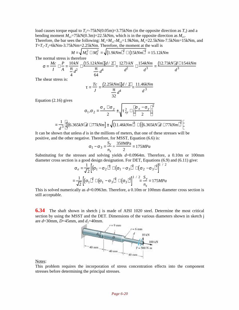
Page 6-20
load causes torque equal to T2=-75kN(0.05m)=3.75kNm (in the opposite direction as T1) and abending moment Mz2=75kN(0.3m)=22.5kNm, which is in the opposite direction as Mz1.Therefore, the bar sees the following: Mx=Mx1-Mx2=1.9kNm, Mz=22.5kNm-7.5kNm=15kNm, andT=T1-T2=6kNm-3.75kNm=2.25kNm. Therefore, the moment at the wall is
M = Mx2 + Mz
2 = 1.9kNm( )2 + 15kNm( )2 = 15.12kNmThe normal stress is therefore
σ =Mc
I+
P
A=
10kNπ4
d2+
15.12kNm( ) d / 2( )π64
d4=
12.73 kN
d2 +154kNm
d3 =12.73kN( )d + 154kNm
d3
The shear stress is:
τ =Tc
J=
2.25kNm( ) d / 2( )π32
d4=
11.46kNm
d 3
Equation (2.16) gives
σ1 ,σ2 =σ x + σ y
2± τ xy
2 +σ x − σy
2
2
=1
d 3 6.365kN( )d + 77kNm[ ] ± 11.46kNm( )2 + 6.365kN( )d + 77kNm( )2
It can be shown that unless d is in the millions of meters, that one of these stresses will bepositive, and the other negative. Therefore, for MSST, Equation (6.6) is:
σ1 − σ3 =Sy
ns=
350MPa
2= 175MPa
Substituting for the stresses and solving yields d=0.0964m. Therefore, a 0.10m or 100mmdiameter cross section is a good design designation. For DET, Equations (6.9) and (6.11) give:
σe =1
2σ1 − σ2( )2 + σ1 − σ3( )2 + σ2 −σ3( )2[ ]1 / 2
= 1
2σ1( )2 + σ1 − σ3( )2 + σ3( )2[ ]1 / 2
=Sy
ns= 175MPa
This is solved numerically as d=0.0963m. Therefore, a 0.10m or 100mm diameter cross section isstill acceptable.
6.34 The shaft shown in shetch j is made of AISI 1020 steel. Determine the most criticalsection by using the MSST and the DET. Dimensions of the various diameters shown in sketch jare d=30mm, D=45mm, and d2=40mm.
Notes:This problem requires the incorporation of stress concentration effects into the componentstresses before determining the principal stresses.
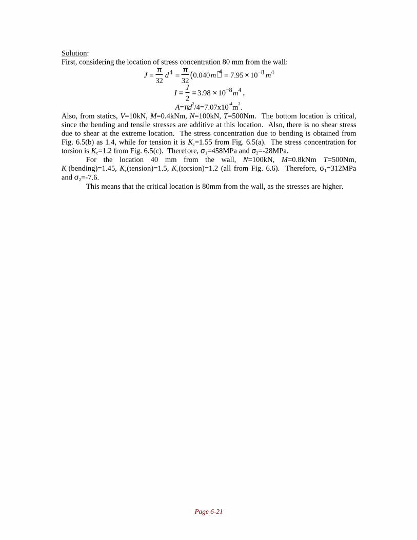
Page 6-21
Solution:First, considering the location of stress concentration 80 mm from the wall:
J =π32
d4 =π32
0.040m( )4 = 7.95 × 10⁻⁸ m4
I =J
2= 3.98 × 10⁻⁸m4 ,
A=πd2/4=7.07x10
-4m
2.
Also, from statics, V=10kN, M=0.4kNm, N=100kN, T=500Nm. The bottom location is critical,since the bending and tensile stresses are additive at this location. Also, there is no shear stressdue to shear at the extreme location. The stress concentration due to bending is obtained fromFig. 6.5(b) as 1.4, while for tension it is Kc=1.55 from Fig. 6.5(a). The stress concentration fortorsion is Kc=1.2 from Fig. 6.5(c). Therefore, σ1=458MPa and σ2=-28MPa.
For the location 40 mm from the wall, N=100kN, M=0.8kNm T=500Nm,Kc(bending)=1.45, Kc(tension)=1.5, Kc(torsion)=1.2 (all from Fig. 6.6). Therefore, σ1=312MPaand σ2=-7.6.
This means that the critical location is 80mm from the wall, as the stresses are higher.

Page 7-1
Chapter 7Failure Prediction for Cyclic and Impact Loading
7.1 A tuning fork is hit with a pencil and starts to vibrate with a frequency of 440Hz. Themaximum bending stress in the tuning fork is 4MPa at the end positions. Calculate themean stress, the range of stress, the stress amplitude, the stress ratio, and the amplituderatio. Also calculate how much stress the tuning fork can sustain without being plasticallydeformed if it is made of AISI 1080 steel.
Notes: Equations (7.1) through (7.5) are used to obtain a solution.
Solution:From Equation (7.1), the mean stress is:
σm = σmax + σmin
2= 4MPa − 4MPa
2= 0
The stress range is given by Equation (7.2) asσr = σmax −σmin = 4MPa − −4 MPa( ) = 8MPa
The stress amplitude is obtained from Equation (7.3) as:
σa = σr
2= 8MPa
2= 4MPa
The stress ratio is obtained from Equation (7.4):
Rs = σmin
σmax= −4MPa
4MPa= −1
The amplitude ratio is given by Equation (7.5):
Aa = σa
σm= 4MPa
0= ∞
From the inside front cover, the yield strength of AISI 1080 steel is 380 MPa, and this is thelargest stress that the material can withstand without permanent deformation.
7.2 The jack for a Volvo consists of a mechanism in which the lift screw extends horizontallythrough two corners of the mechanism while the other two corners apply a force betweenthe ground and the car to be lifted. The maximum compressive stress in the jack is 190MPa when the Volvo is jacked up so high that both wheels on one side of the car are inthe air and the load on the jack is 8000N. How many times can the jack be used for asmall truck that weighs 6 tons and loads the jack to 17000N before the jack fails fromfatigue? The jack material is 1080 steel.
Notes: The first step is to determine which regime of fatigue is applicable by comparing the stressto the fatigue strengths from Equations (7.7) and (7.8). The jack is in high-cycle, finite life, sothat Equation (7.15) is used to determine the number of cycles to failure.
Solution:From the inside front cover for AISI 1080 steel, Su=615MPa and Sy=380MPa. Since the stress isproportional to load, the stress encountered by the jack in raising the truck is:

Page 7-2
σ = Ftσc
Fc= 17000N( ) 190MPa( )
8000N= 403.8MPa
From Equation (7.7), the stress endurance limit is:
Se′ = 0.45Su = 0.45 615MPa( ) = 276.8MPa
While from Equation (7.8), the fatigue strength where high-cycle fatigue begins is:Sl
’=0.75Su=0.75(615MPa)=461.3MPaSince the applied stress is between these two levels, the jack encounters high-cycle, finite-lifefatigue. From Equations (7.12) and (7.13),
bs = −13
logSl
′
Se′
= − 1
3log
461.3MPa276.8MPa
= −0.07394
C = logSl
′( )2
Se′
= log461.3( )2
276.8
= 2.8858
Therefore, the number of cycles until failure is, from Equation (7.15),
Nt′ = S f
′ 10−C ( )1/ b s= 403.8( )10−2.8858( )1 /−0.07394( )
= 6052
This is the approximate number of cycles until failure.
7.3 The shaft shown in sketch a rotates at high speed while the imposed load remains static.The shaft is machined from ground, high carbon steel (AISI 1080). If the loading issufficiently large to produce a fatigue failure after 1 million cycles, where would thefailure most likely occur? Show all necessary computations and reasoning.
Notes: The failure is expected to be due to bending, since the stresses are completely reversing.Once must therefore investigate all likely locations to determine the maximum normal stress,including the effects of stress concentrations.
Solution:Note the locations a, b, c, and d in the figure, which are the probable failure locations,
either because of stress concentration (a, c, d) or because the loading is largest (b). Upon furtherinspection, the difference between shoulder a and d is the radius. Since the radius is smaller forthe left shoulder than the right one, it will have a higher stress concentration factor, and the rightshoulder doesn’t have to be considered. In terms of the analysis to be followed, there are nodifferences between the locations in the shaft in terms of manufacturing method, size effects,temperature effects, reliability, etc, except that the fatigue stress concentration factor must becalculated. Also, from the inside front cover, AISI 1080 steel has an ultimate strength of 89ksi.

Page 7-3
I. Left ShoulderTaking a section at point a, the moment is M=(P/2)(1in), with the diameter equal to 1 in. Thestress concentration is obtained from Figure 6.5 (b), using D/d=1.12in/1in=1.25 andr/d=(1/16in)/1in=0.0625, so that Kc=1.75. From Figure 7.6 on page 272, qn is about 0.75.Therefore, from Equation (7.19),
Kf=1+(Kc-1)qn=1+(1.75-1)(0.75)=1.56The maximum stress at a is:
σ = K fMc
I= 1.56( )
0.5in( )P( ) 0.5in( )π64
1in( )4= 7.94in−2( )P
II. Midpoint of ShaftAt the midpoint, the bending moment is M=(P/2)(3in)=(1.5in)P. The diameter of the shaft is1.25in at this location. There is no stress concentration here, so the maximum stress is given byEquation (4.48) as:
σ =Mc
I=
1.5in( )P( ) 1.25in / 2( )π64
1.25in( )4= 7.82in−2( )P
III. GrooveTaking a section at the groove, the moment is M=(P/2)(2in)=(1in)P. Although the diameter is notspecified at this location, it is reasonable to approximate it as 1in. Kc is obtained from Figure6.6(b), using D/d=1.25in/1in=1.25 and r/d=(1/8in)/1in=0.125, so that Kc=1.7. From Figure 7.6, qn
is around 0.85. Therefore, from Equation (7.19),Kf=1+(Kc-1)qn=1+(1.7-1)(0.85)=1.595
The maximum stress is
σ = K fMc
I= 1.595( )
1in( )P( ) 0.5in( )π64
1in( )4= 16.2in−2( )P
IV. SummarySince the stress is largest at the groove, this is the most likely fatigue failure location.
7.4 For each of the bars shown in sketches b and c, which are made of AISI 1040 cold drawnsteel, determine
a) The static tensile load causing failureb) The alternating (completely reversing) axial load ±P that would be just on the verge of
producing eventual fatigue failure.
Notes: The discussion on page 227 suggests that stress concentrations are relieved by plasticdeformation under static loads; certainly this mild steel will relieve the stresses so that they areignored. The stress concentration is not ignored for the fatigue failure. Also, a surface correctionfactor kf is calculated from Equation (7.21).
Solution:

Page 7-4
For AISI 1040 steel, the inside front cover gives Sut=75ksi=520MPa. Since the material is ductile,stress concentration are ignored (see discussion on page 227). Therefore, the critical load foreither bar is:
P=σA=(520MPa)(0.025m)2=325kN
For a fatigue loading, and the bar in sketch b (without a notch), we note from Equation(7.7) for axial loading:
Se’=0.45Su=0.45(520MPa)=234MPa
The bar may be cold drawn, but the notch must be machined; either case gives, from Table 7.3,that e=4.51MPa, and f=-0.265. Therefore, from Equation (7.21),
k f = eSutf = 4.51 520( )−0.265 = 0.86
The size factor is ks=1 for axial loading (see page 275). All other factors are ignored. Therefore,from Equation (7.16),
Se=kfkskrktkmSe’=(0.86)(1)(234MPa)=201MPa.
For the notched bar, from Figure 6.4(a) for H/h=30/25=1.2 and r/h=2.5/25=0.1, we getKc=2.35. From Figure 7.6 on page 272 we get for Sut=520MPa and r=2.5mm that qn=0.75(approx). Therefore, Equation (7.19) gives
K f = 1 + Kc − 1( )qn = 1 + 2.35 −1( ) 0.75( ) = 2.01For the unnotched bar, there is no stress concentration, so we set the applied stress equal
to the endurance limit:sall=Pall/A=Se; Pall=SeA=(201MPa)(0.025m)2=126kN
For the notched bar, the endurance limit must be reduced by the factor Kf:
σall =P
A=
Se
K f;P =
SeA
K f=
201MPa( ) 0.025m( )2
2.01= 62.5kN
Note that slightly different answers are acceptable; numbers read off charts can be slightlydifferent, and there can be small discrepancies between using Equation (7.21) versus Figure 7.7.
7.5 A stepped shaft, as shown in sketch d, has a major diameter of 2 in, a minor diameter of 1in, and a notch radius of 0.1 in. It was machined from high-carbon steel (AISI 1080). Theloading is one of completely reversed torsion. During a typical 30s of operation underoverload conditions, the nominal stress in the 1-in diameter section was measured to beas shown in sketch e. Estimate the life of the shaft when it is operating continually underthese conditions.
Notes: The modified endurance limit has to be calculated using a surface finish factor, fatiguestress concentration factor, and size factor. The life at each stress is calculated from Equation(7.15), and the total life is calculated from Miner’s Rule, Equation (7.24).
Solution:
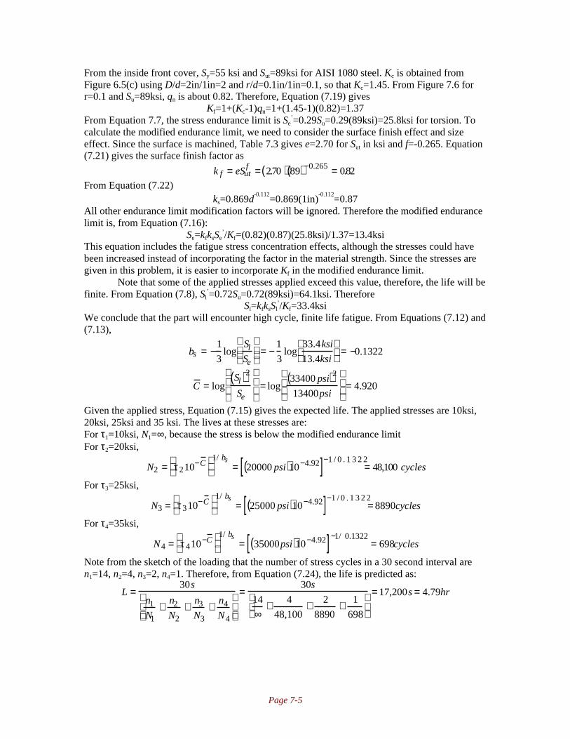
Page 7-5
From the inside front cover, Sy=55 ksi and Sut=89ksi for AISI 1080 steel. Kc is obtained fromFigure 6.5(c) using D/d=2in/1in=2 and r/d=0.1in/1in=0.1, so that Kc=1.45. From Figure 7.6 forr=0.1 and Su=89ksi, qn is about 0.82. Therefore, Equation (7.19) gives
Kf=1+(Kc-1)qn=1+(1.45-1)(0.82)=1.37From Equation 7.7, the stress endurance limit is Se
’=0.29Su=0.29(89ksi)=25.8ksi for torsion. Tocalculate the modified endurance limit, we need to consider the surface finish effect and sizeeffect. Since the surface is machined, Table 7.3 gives e=2.70 for Sut in ksi and f=-0.265. Equation(7.21) gives the surface finish factor as
k f = eSutf = 2.70( ) 89( )−0.265 = 0.82
From Equation (7.22)ks=0.869d
-0.112=0.869(1in)
-0.112=0.87
All other endurance limit modification factors will be ignored. Therefore the modified endurancelimit is, from Equation (7.16):
Se=kfksSe’/Kf=(0.82)(0.87)(25.8ksi)/1.37=13.4ksi
This equation includes the fatigue stress concentration effects, although the stresses could havebeen increased instead of incorporating the factor in the material strength. Since the stresses aregiven in this problem, it is easier to incorporate Kf in the modified endurance limit.
Note that some of the applied stresses applied exceed this value, therefore, the life will befinite. From Equation (7.8), Sl
’=0.72Su=0.72(89ksi)=64.1ksi. ThereforeSl=kfksSl
’/Kf=33.4ksiWe conclude that the part will encounter high cycle, finite life fatigue. From Equations (7.12) and(7.13),
bs = −1
3log
Sl
Se
= −
1
3log
33.4ksi
13.4ksi
= −0.1322
C = logSl( )2
Se
= log
33400 psi( )2
13400psi
= 4.920
Given the applied stress, Equation (7.15) gives the expected life. The applied stresses are 10ksi,20ksi, 25ksi and 35 ksi. The lives at these stresses are:For τ1=10ksi, N1=∞, because the stress is below the modified endurance limitFor τ2=20ksi,
N2 = τ210−C
1/ bs
= 20000 psi( )10−4.92[ ]−1 / 0 . 1 3 2 2= 48,100 cycles
For τ3=25ksi,
N3 = τ310−C
1/ bs
= 25000 psi( )10−4.92[ ]−1 / 0 . 1 3 2 2= 8890cycles
For τ4=35ksi,
N4 = τ410−C
1/ bs
= 35000psi( )10−4.92[ ]−1/ 0.1322= 698cycles
Note from the sketch of the loading that the number of stress cycles in a 30 second interval aren1=14, n2=4, n3=2, n4=1. Therefore, from Equation (7.24), the life is predicted as:
L =30s
n1
N1+ n2
N2+ n3
N3+ n4
N4
=30s
14
∞+ 4
48,100+ 2
8890+ 1
698
= 17,200s = 4.79hr

Page 7-6
7.6 A flood-protection dam gate is supposed to operate only once per week for 100 years, butsuddenly after 30 years of use it needs to be operated twice per day (each time the hightide comes in). Find how much lower the bending stress must be from then on to still givea total life of 100 years. The material being fatigued is medium-carbon steel (AISI 1040).
Notes: This problem is solved through application of Equation (7.14), requiring equations (7.12)and (7.13).
Solution:From the inside front cover, the ultimate strength of AISI 1040 steel is Su=520MPa. The originalintended life was (100years)(52weeks/year)(1cycle/week)=5200 cycles. The used life is0.3(5200)=1560 cycles. If the gate will be operated twice a day for 70 years, the number of cyclesit must survive is (70years)(365.25days/year)(2cycles/day)=51100cycles. From Equation (7.8),recognizing the loading is bending,
Sl’=0.9Su=0.9(520MPa)=468MPa
Also, from Equation (7.7) for bendingSe
’=0.5Su=0.5(520MPa)=260MPaFrom Equation (7.24), the required life is:
n1N1
+n2
N2= 1=
1560
5200+
51100
N2; N2 = 73000cycles
From Equations (7.12) and (7.13),
bs = −1
3log
Sl′
Se′
= −
1
3log
468MPa
260 MPa
= −0.08509
C = log′ S l( )2
′ S e
= log
468MPa( )2
260 MPa
= 8.9255
Therefore, the allowable stress level for N=73000 cycles is given by Equation (7.14) as:
S f′ = 10C N( )bs = 108.9255 73000( )−0.08509 = 325MPa
Note that for the original design, the allowable stress level was:
S f′ = 10C N( )bs = 108.9255 5200( )−0.08509 = 407MPa
so the new stress level is roughly 20% lower than the original case.
7.7 A hydraulic cylinder has a piston diameter D=100mm and a piston rod diameterd=33mm. The hydraulic pressure alternately applied to each side of the piston isp=300bars. The pressure induces in the rod a compressive force of πpD
2/4 or a tensile
force of πp(D2-d
2)/4, depending on which side of the piston the pressure is applied. The
piston rod material is martensitic stainless steel (AISI 410). Find the endurance life of thepiston rod.
Notes: One must calculate the stresses and compare them to the endurance strength of thematerial to determine which regime of fatigue is appropriate. The life is obtained from Equation(7.15).
Solution:From the inside front cover, the ultimate strength of AISI 410 stainless steel is Su=483MPa andthe yield strength is Sy=275MPa. From equations (7.7) and (7.8) for axial loading,
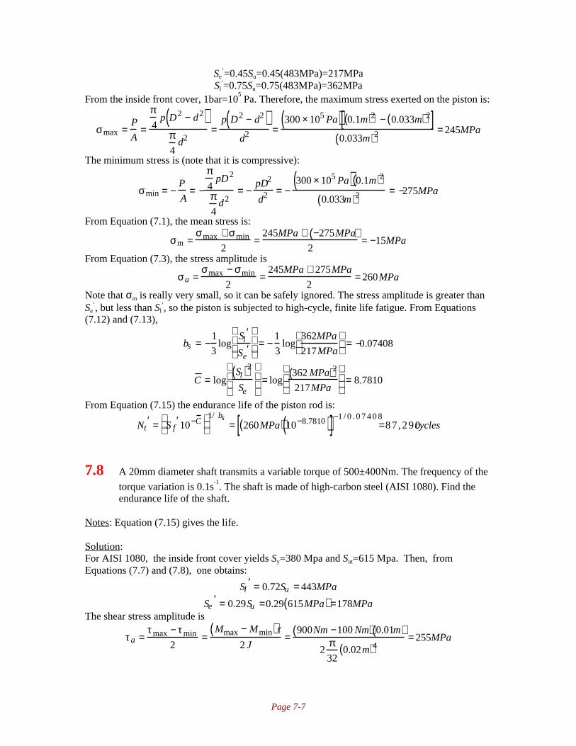
Page 7-7
Se’=0.45Su=0.45(483MPa)=217MPa
Sl’=0.75Su=0.75(483MPa)=362MPa
From the inside front cover, 1bar=105 Pa. Therefore, the maximum stress exerted on the piston is:
σmax =P
A=
π4
p D2 − d2( )π4
d2=
p D2 − d2( )d2 =
300 × 105 Pa( ) 0.1m( )2 − 0.033m( )2[ ]0.033m( )2 = 245MPa
The minimum stress is (note that it is compressive):
σmin = −P
A= −
π4
pD2
π4
d2= −
pD2
d2 = −300 × 105 Pa( ) 0.1m( )2
0.033m( )2 = −275MPa
From Equation (7.1), the mean stress is:
σm =σmax + σmin
2=
245MPa + −275MPa( )2
= −15MPa
From Equation (7.3), the stress amplitude is
σa =σmax − σmin
2=
245MPa + 275MPa
2= 260MPa
Note that σm is really very small, so it can be safely ignored. The stress amplitude is greater thanSe
’, but less than Sl’, so the piston is subjected to high-cycle, finite life fatigue. From Equations
(7.12) and (7.13),
bs = −1
3log
Sl′
Se′
= −
1
3log
362MPa
217MPa
= −0.07408
C = logSl( )2
Se
= log
362 MPa( )2
217MPa
= 8.7810
From Equation (7.15) the endurance life of the piston rod is:
Nt′ = S f
′10−C
1/ bs
= 260MPa( ) 10−8.7810( )[ ]−1 / 0 . 0 7 4 0 8=87 ,290cycles
7.8 A 20mm diameter shaft transmits a variable torque of 500±400Nm. The frequency of the
torque variation is 0.1s-1. The shaft is made of high-carbon steel (AISI 1080). Find the
endurance life of the shaft.
Notes: Equation (7.15) gives the life.
Solution:For AISI 1080, the inside front cover yields Sy=380 Mpa and Sut=615 Mpa. Then, fromEquations (7.7) and (7.8), one obtains:
Sl′ = 0.72Su = 443MPa
Se′ = 0.29Su =0.29 615MPa( ) =178MPa
The shear stress amplitude is
τa =τmax − τmin
2=
Mmax − Mmin( )r
2 J=
900Nm −100 Nm( ) 0.01m( )2
π32
0.02m( )4= 255MPa

Page 7-8
Note that this value is indeed between Sl’ and Se’, so it will fail under a finite number of cycles.The life is given by equation (7.15):
N = S f′10−C( )1/ b
From Equations (7.12) and (7.13) as:
C = logSl
′( )2
Se′
= log443x106( )2
178x106 = 9.04
bs = −1
3log
Sl′
Se′
= −0.132
So that the number of cycles for which 255MPa would cause failure, that is, for Sf’=255Mpa,
N = 255x106( ) 10−9.04( )( )−1 / 0 . 1 2 8 7= 62 ,900cycles
For a frequency of 0.1 cycles per second, this results in a life of 174 hrs.
7.9 Find for the shaft in Problem 7.8 how large the shaft diameter has to be to give infinitelife.
Notes: The stress amplitude must equal the fatigue endurance limit for this case. This solutionuses the results of Problem 7.8.
Solution:From Problem 7.8, Se
’=178MPa. The shear stress amplitude is
τa =τmax − τmin
2=
Mmax − Mmin( ) d
2J
=900Nm − 100Nm( ) d
2
2π32
d4=
2037Nm
d3
For infinite life, the shear stress amplitude must be less than or equal to Se’. Therefore,
τa = 178MPa =2037Nm
d 3 ; d = 0.0225m = 22.5 mm
7.10 A notched bar has the diameter D=25mm and the notch radius r=0.5mm. It experiencesrotational bending fatigue. The bottom diameter of the notch is 24mm. Find which of thesteels AISI 1020, 1040, 1080, or 316 will give the highest allowable bending moment forinfinite life. Calculate that moment.
Notes: This problem requires calculation of endurance limit and fatigue stress concentrationfactors for the metals under consideration.
Solution:For the materials given, the following data can be obtained from the inside front cover:Alloy Su (MPa) Sy (MPa) qn
102010401080
395520615
295350380
0.40.580.62

Page 7-9
316 552 207 0.60The notch sensitivity is read from Figure 7.6 on page 272 and placed in the last column above.Also, from Figure 6.6 (b) on page 226, with D/d=25/24=1.04 and r/d=0.5/24=0.021, Kc=2.5.The fatigue stress concentration factor for each alloy is then given by Eq. 7.19 and equals for1020: 1.6; 1040: 1.87; 1080: 1.93; 316:1.9. To compare the alloys, one can reduce theendurance limit by 1/Kf per the discussion on page 271. The allowable stresses after reducing theendurance limit by the fatigue stress concentration factors are then, from (7.7): Se=0.5Su/Kf;1020: 123MPa; 1040: 139 MPa; 1080: 159 MPa; 316: 145. Of these, the 1080 alloy gives thehighest allowable stress. The moment which is allowable in AISI 1080 is
Se =Se
′
K f= 159MPa =
Mc
I= M
0.012mπ64
0.024m( )4
;M = 215Nm
7.11 A straight, circular rotating beam has a diameter of 30mm and a length of 1m. At the endof the beam a stationary load of 500N is applied perpendicularly to the beam, giving abending deformation. Find which surface machining method can be used to give infinitelife to the rotating beam if it is made of:a) AISI 1020 steelb) AISI 1080 steelNote that ks=kr=km=1
Notes: The bending stress is obtained from Equation (4.48). The endurance limit is obtained fromEquation (7.7), and the modified endurance limit from (7.16) with only the surface correctionfactor (kf) incorporated.
Solution:First of all, note that the bending stress is, from Equation (4.48):
σ =Mc
I=
M d / 2( )π64
d4
=500N( ) 1m( ) 0.03m( ) /2
π64
0.03m( )4
=188.6MPa
For infinite life, the modified endurance limit must be greater than this stress.I. AISI 1020 SteelFrom the inside front cover, Sut=395MPa. Therefore, from Equation (7.7) for bending,
Se′ = 0.5Su = 0.5 395MPa( ) = 197.5MPa
From Equation (7.16) and the requirement that Se≥σ,
Se = k f Se′ ≥ σ = 188.6MPa; k f ≥
188.6 MPa
197.5MPa= 0.954
Reviewing Figure 7.7, the only acceptable surface finish is polished. Even a ground surface giveskf of around 0.9, which would result in finite life.II. AISI 1080 Steel.From the inside front cover, Sut=615MPa. Therefore, from Equation (7.7) for bending,
Se′ = 0.5Su = 0.5 615MPa( ) = 307.5MPa
From Equation (7.16) and the requirement that Se≥σ,
Se = k f Se′ ≥ σ = 188.6MPa; k f ≥
188.6 MPa
307.5MPa= 0.61
Reviewing Figure 7.7, the acceptable finishes come from polishing, grinding, machining or colddrawing. Hot rolling is marginal; it may be acceptable, but probably not.

Page 7-10
7.12 The pedals on a bicycle are screwed into the crank with opposite threads, one left-handthread and one right-hand thread, to ensure that the pedals do not accidentally unscrew.Just outside the thread is a 0.75-mm radius fillet connecting the 12.5mm-diameterthreaded part with an 11-mm diameter central shaft in the pedal. The shaft is made ofAISI 4340 alloy steel tempered at a low temperature to give an ultimate stress of 2GPa.Find the fatigue stress concentration factor for the fillet, and calculate the maximumallowable pedal force for infinite life if the force from the foot is applied 70mm from thefillet.
Notes: The fatigue stress concentration factor must be calculated from Equation (7.19).Insufficient information is given to obtain any endurance limit modification factors, so thissolution is based on maintaining a stress below Se
’.
Solution:The stress concentration factor is obtained from Figure 6.5(b) using
r/d=0.75mm/11mm=0.068 and D/d=12.5mm/11mm=1.14, so that Kc=1.75. The notch sensitivityis obtained from Figure 7.7 as qn=0.95. Therefore, Kf is obtained from Equation (7.19) as:
Kf=1+(Kc-1)qn=1+(1.75-1)(0.95)=1.71Therefore, since the moment is P(0.07m), the bending stress is
σ = K fMc
I= 1.71( ) P 0.07m( ) 0.011m / 2( )
π64
0.011m( )4= 9.16 × 10⁵m−2( )P
Note that the fatigue stress concentration factor has been used to increase the stress; it could havebeen used to reduce the allowable strength to get the same result. For bending, the endurancelimit of the material is obtained from Equation (7.7) as Se’=0.5Su=0.5(2GPa)=1GPa. Therefore,equating the stress to the strength:
σ = 9.16 × 10⁵ m−2( )P = Se′ = 1GPa; P =1090N
7.13 A saddle pole for a mountain bike has a fillet of 5-mm radius connecting the top part ofthe pole (which has a diameter of 35mm) with the bottom part of the pole (which has adiameter of 25 mm). The saddle pole is solid and made of 2024 aluminum. Find thefatigue stress concentration factors for axial load and bending.
Notes: The theoretical stress concentration factor (Kc) can be obtained from the Figure 6.5 onpage 225. To get the fatigue stress concentration factors, one needs to use the notch sensitivityfrom Figure 7.6, and Equation (7.19).
Solution:For this pole, r/d=5/25=0.2 and D/d=35/25=1.4. Therefore, from Figure 6.5 on page 225, Kc foraxial loading is roughly 1.55 and for bending Kc is about 1.375. From Figure 7.6 with r=5 mmand extrapolating off the chart, qn is approximately 0.8, so Kf is, from Equation (7.19), and axialloading:
K f = 1 + Kc − 1( )qn = 1 + 1.55 −1( ) 0.8( ) = 1.44For bending, Equation (7.19) becomes:
K f = 1 + Kc − 1( )qn = 1 + 1.375 − 1( ) 0.8( )= 1.3

Page 7-11
7.14 During the development of a new submarine a 1-to-20 model was used. The model wastested to find if there was any risk of fatigue failure in the full-scale submarine. To be onthe safe side, the stresses in the model were kept 15% higher than the stresses in the full-size submarine. Is it possible to conclude that the full-size submarine will be safe if themodel was safe at a 15% higher stress level?
Notes: This involves consideration of the size factor, Equation (7.22).
Solution:Some portions submarine may be effectively modeled with a scale model. However, consider abending or tension specimen, where all features are the same, but the size is smaller. FromEquation (7.22), the size factor for the scale model (m subscript) and the full-sized submarine (fsubscript) are:
ksm = 1.189dm−0.112
ksf = 1.189d f−0.112 =1.189 20dm( )−0.112 = 20( )−0.112ksm = 0.715ksm
Therefore, for the model has to be stressed at (1/0.715)=1.399 times the full size submarine stresslevel. The model’s survival does not guarantee the success of the full-sized submarine.
7.15 During the development of a new car it was found that the power from the motor was toohigh for the gearbox to handle. When maximum torque was transmitted through thegearbox, 50% of the gearboxes failed within the required lifetime of 800 hours. Howmuch stronger should the gearbox be made to ensure that only one gearbox out of 1000would fail within 800hr?
Notes: This problem requires application of the reliability factor.
Solution:Referring to Table 7.4 on page 275, the reliability factor is kr=1.00 for 50% failures. If one out ofone thousand were to fail, that is, for a reliabilty of 99.9%, kr=0.75. Therefore the strength shouldbe increased by (1/0.75)=1.33. Therefore, the gearbox should be 33% stronger.
7.16 Truck gearboxes are dimensioned for infinite life at maximum torque regarding contactstresses and bending stresses for all gear steps. Car gearboxes are dimensioned for finitelife according to typical running conditions. Maximum torque for the first gear cantypically be maintained only 3 to 6s for each acceleration before the maximum speed isreached. If a driver accelerates at full power 20 times per day for 20 years on the firstgear, the required life is only 60 to 120hr. The normal load spectrum gives a life of200,000 km for 99% of the gearboxes. A driver uses the car twice a year to move his 10-ton boat 50km, the distance between his home and the harbor, during the 10-year life ofthe car. Calculate how much of the 200,000km nominal life of the gearbox is consumedby the boat moving if the life is inversely proportional to the load raised to the 3.5 power.During the move the gearbox load is four times higher than normal.

Page 7-12
Notes: This problem requires application of Miner’s Rule, Equation (7.24).
Solution:Use an n subscript for the normal use condition and a b subscript for hauling the boat. The loadon the gear box is 4 times higher than normal during the 100km/year (50km to the harbor and50km going back). At four times higher load, the life of the gearbox is
Nb = 200,000km
43.5 = 1563km
Therefore, from Equation (7.24)
nn′
Nn′ + nb
′
Nb′ = 1; nn
′ = Nn′ 1− nb
′
Nb′
= 200,000( ) 1−
10yr( ) 100km / yr( )1563km
= 72,000km
Therefore, moving the boat consumes 64% of the gearbox life.
7.17 The hand brakes of a bicycle are often the same type for the front and rear wheels. Thehigh center of gravity (compared with the distance between the wheels) will increase thecontact force between the front wheel and the ground and will decrease the contact forcebetween the rear wheel and the ground when the brakes are applied. If equal force isapplied to each of the two brakes, the rear wheel will start sliding while the front wheel isstill rolling. The manufacturer of the brake wires did not know about this differencebetween the front and rear wheels, so the wires were dimensioned as if the wheels hadequal contact force and thus needed equal force in the two brake wires. The wires wereoriginally dimensioned to withstand 20 years’ use with brake applications at a forcenecessary to lock the two (equally loaded) wheels. How long will the life of the wires beif the friction between the front wheels and the ground is just enough to lift the rear wheelfrom the ground? Assume the endurance life is proportional to the stress raised to the -10power.
Solution:When both wheels brake the bike, the wire force on each brake is half of the force needed tobrake the bike with only one brake. Since the endurance life is proportional to the stress raised tothe -10, the life for the front brake is 2
-10=9.766x10
-4 times the calculated life, which was 20
years. The life is
L = 20years( ) 9.766 ×10⁻⁴( ) = 0.01953yr = 7.129days
Thus the life is only seven days instead of 20 years.
7.18 Ball bearings often run at varying load and speed. Life is inversely proportional to thecontact stress raised to the 31/3 power for a number of bearing types. For ball bearingsthe contact stresses are approximately proportional to the third root of the load. A ballbearing in a gearbox is dimensioned to have a life of 1752 million revolutions, half ofwhich are at half of the maximum motor torque, one-quarter at full motor torque, andone-quarter at 75% of full motor torque. Calculate the bearing life if the motor torque iskept constant at the maximum level.
Notes: This problem requires application of Miner’s Rule, Equation (7.24).
Solution:

Page 7-13
Let the full motor torque give the life L1. 75% of the full motor load gives the life of
L75 = L1
0.75( )3 1 / 9= 2.694L1
and 50% of the full motor torque gives a life of
L50 = L1
0.50( )31/9 = 10.89L1
For a total life of 1752 million revolutions, 876 million will be at maximum motor torque, and438 million will take place at 75% and 50% torque. Therefore, Equation (7.24) gives:
n1′
N1′ + n2
′
N2′ + n3
′
N3′ = 1= n100
′
N100′ +
n50′
N50′ +
n75′
N75′ = 876×106
L1+ 438×106
10.89 L1+ 438× 106
2.694L1
Solving for L1 gives L1=681 million. Therefore, the life at maximum torque is 681 millionrevolutions.
7.19 A circular cold-drawn steel bar with a solid cross section is subjected to a cyclic forcethat ranges from a maximum of 80,000 lbf in tension to a minimum of 30,000 lbf incompression. The ultimate strength is 158,000 psi and the yield strength is 133,000 psi.The critical safety factor is 2. Determine the following:a) The modified endurance limitb) The cross-sectional area that will produce fatigue failure and the correspondingdiameter.c) The region (a, b, c, or d) assuming modified Goodman criteria, and why.
Notes: A surface finish factor must be calculated, all other factors are proven or assumed to beone. The region in the modified Goodman criteria follows from Table 7.6 on page 285.
Solution:Since the bar is steel, the stress endurance limit can be obtained from Equation (7.7) as:
Se’=0.45Su=0.45(158ksi)=71.1ksi
The modified endurance limit will be calculated from Equation (7.16), but correction factors needto be calculated first. No information exists regarding stress concentrations, so we will assumeKf=1. The surface finish factor is calculated from Equation (7.21), using e=2.70 and f=-0.265 asobtained from Table 7.3 on page 274. Therefore, kf is:
k f = eSutf = 2.70( ) 158( )−0.265 = 0.706
(Note that kf could also be read from Figure 7.7 as around 0.68, which is close to the valuecalculated from Equation (7.21)). As discussed on page 275, ks=1 for axial loading. Noinformation is given to suggest reliability, temperatures or other effects are important, so we takekr=kt=km=1. Therefore, Equation (7.16) gives:
Se=kfkskrktkmSe’=(0.706)(71.1ksi)=50.20ksi
From Equation (7.1), the mean stress is:
σm = σmax + σmin
2= Pmax + Pmin
2A=
80kip + −30kip( )2A
= 25kipA
We will use the modified Goodman relationship, as required in the problem statement. Note thatSe-Sy=50.2ksi-133ksi=--82.8ksi. Referring to Table 2.6 on page 285, region a therefore cannot bethe one corresponding to this stress state. Neither can region b, since σm>0. Therefore, eitherregion c or d is the proper one, and it will not be known which region is correct until after afailure equation has been applied. Assume the stress state is described by region c. Therefore, thefailure equation from Table 7.6 gives:

Page 7-14
σmax + σmSe
K f Su−1
=
Se
nsK f;
80kipA
+ 25kipA
50.2ksi158ksi
−1
= 55ksi
2
Solving for A gives A=2.29in2, so d=1.71 in. The mean stress is then
σm = 25kipA
= 25kip
2.29in2 = 10.9ksi
Referring to Table 7.6, and recognizing that Kf=1, Region c requires:
σm ≤Sy − Se
1− Se
Su
= 133ksi − 50.2ksi
1− 50.2ksi
158ksi
= 121ksi
Since this is true, region c is the correct region of the modified Goodman relationship.
7.20 Both bars used in Problem 7.4 and shown in sketches b anc c are made from cold-drawn,medium-carbon steel (AISI 1040). Determine the safety factor for each bar. The loadvaries from 10 to 40 kN. Use the modified Goodman relationship.
Notes: This problem is similar to problem 7.19. The region in the modified Goodman criteriafollows from Table 7.6 on page 285.
Solution:From the inside front cover, Su=520 MPa and Sy=350 MPa. From Equation (7.7), the endurancelimit is 0.45 Su=234 MPa. From Figure 7.7 (a) on page 273, the surface finish factor is kf=0.77.For axial loading, the size factor is 1 (see text on page 275), and no further information is given.Therefore the modified endurance limit is Se=(0.77)(234MPa)=180MPa.I. Unnotched Bar:Here the maximum stress is σmax=(40,000N)/(0.025m)2=64 MPa. The mean stress isσm=(25,000N)/(0.025m)2=40MPa. Note that the mean stress is positive, so either region c or dfrom Figure 7.10 on page 283 is active; we calculate
Sy −Se
K f
1 −Se
K f Su
=350MPa −
180MPa
1
1 −180MPa
(1)(520 MPa)
= 260MPa
Since the mean stress is less than this value, we conclude that region (c) is active (see Table 7.6,page 285). Therefore, the failure equation is, from Table 7.6 on page 285,
σmax + σmSe
K f Su−1
=
Se
nsK f;64 MPa+ 40MPa
180MPa
(1)(520 MPa)−1
=
180MPa
1(ns );ns = 4.75
II. Notched barHere there is a stress concentration factor of Kc=2.4 and a notch sensitivity of about 0.775.Therefore, Kf=1+(2.4-1)(0.775)=2.085~2.1 The maximum and mean stresses are the same sincethe root area is the same. Again, to determine if the active region is c or d we calculate
Sy −Se
K f
1 −Se
K f Su
=350MPa − 180MPa
2.1
1 −180MPa
(2.1)(520MPa)
= 316MPa

Page 7-15
So again the active region is c, and the safety factor is calculated as before and equals 2.8.
7.21 The 7/16 in thick component in sketch f is designed with a filletand a hole. The load varies from 12000 to 2000 lbf. Thefollowing strengths are given: Su=56ksi, Sy=41ksi. Using theGoodman failure theory, determine the safety factor for the holeas well as the fillet. At which location will failure occur first?Will the component fail?
Notes: One must obtain the fatigue stress concentration factors from thetheoretical stress concentration factor, the notch sensitivity andEquation (7.19). The endurance limit is obtained from Equation (7.7).Insufficient information is given about the part to calculate anycorrection factors for Equation (7.16) so Se is taken as Se
’. Equation(7.28) gives the safety factor. Note that the errata suggests using a 3mmradius; either approach gives full credit for the homework.
Solution:Note that from Equation (7.7) for axial loading, Se
’=0.45Su=0.45(56ksi)=25.2ksi. Consider thehole and the fillet separately.I. HoleNote that d/b=0.75/1.875=0.4, so from Figure 6.2(a) on page 222, Kc=2.22. From Figure 7.6,qn=0.78. Therefore, from Equation (7.19),
K f = 1 + Kc − 1( )qn = 1 + 2.22 − 1( ) 0.78( ) =1.95Note for the hole that the maximum and minimum nominal stresses are:
σmax =Pmax
h w − d( )=
12,000 lb
0.4375in( ) 1.875in − 0.75in( )= 24.38ksi
σmin =Pmin
h w − d( )=
2,000 lb
0.4375 in( ) 1.875 in − 0.75in( )= 4.063ksi
Therefore, the alternating and mean stresses are, from Equations (7.3) and (7.1), respectively:
σa =σmax − σmin
2=
24.38ksi − 4.063ksi
2= 10.16ksi
σm =σmax + σmin
2=
24.38ksi + 4.063ksi
2= 14.22ksi
Note that
Sy − Se
K f
1 − Se
K fSu
=41ksi − 25.2ksi
1.95
1− 25.2ksi
1.95 56ksi( )
= 36.5ksi
Since this is greater than σm, we conclude we are in region c of the modified Goodman diagram.Therefore, the failure criterion is taken from Table 7.6 on page 285 as:
σmax + σmSe
K f Su− 1
= 24.38ksi + 14.22ksi( ) 25.2ksi
1.95 56ksi( )− 1
=
Se
nsK f=
25.2
ns 1.95( )or ns=0.96.II. Fillet

Page 7-16
For this geometry, r/h=0.25/1.375=0.18 and H/h=1.875/1.375=1.36. Therefore, from Figure6.3(a) on page 223, Kc=1.6. From Figure 7.6 for r=0.25in and Su=56ksi, qn=0.78. Therefore, fromEquation (7.19),
K f = 1 + Kc − 1( )qn = 1 + 1.6 − 1( ) 0.78( ) = 1.468The maximum and minimum stresses are:
σmax =Pmax
hw=
12,000 lb
1.375in( ) 0.4375( )=19.95ksi
σmin =Pmin
hw=
2,000 lb
1.375in( ) 0.4375( )= 3.325ksi
Therefore, the alternating and mean stresses are, from Equations (7.3) and (7.1), respectively:
σa =σmax − σmin
2=
19.95ksi − 3.325ksi
2= 8.31ksi
σm =σmax + σmin
2=
19.95ksi + 3.325ksi
2= 11.64ksi
Again, note that
Sy − Se
K f
1 − Se
K fSu
=41ksi − 25.2ksi
1.468
1− 25.2ksi
1.468 56ksi( )
= 34.37ksi
Since this is greater than σm, the failure equation is, from Table 7.6 on page 285,
σmax + σmSe
K f Su− 1
= 19.95ksi + 11.64ksi( ) 25.2ksi
1.468 56ksi( )−1
=
Se
nsK f=
25.2
ns 1.468( )Solving for ns gives ns=1.44. Therefore, the component will fail, and it will fail first at the hole.
7.22 The flat bar shown in sketch g is made of cold-drawn, high carbon steel (AISI 1080). Thecyclic, nonzero, mean axial load variation is from a minimum of 2kN to a maximum of10kN. Using the modified Goodman failure theory, determine the safety factors for thehole, the fillet and the groove. Also, indicate where the flat bar will first fail.
Notes: The hole, notch and fillet must each be analyzed separately. One must obtain the fatiguestress concentration factors from the theoretical stress concentration factor, the notch sensitivityand Equation (7.19). The endurance limit is obtained from Equation (7.7). Insufficientinformation is given about the part to calculate any correction factors for Equation (7.16) so Se istaken as Se
’. Equation (7.28) gives the safety factor.
Solution:First of all, note that for AISI 1080 steel, Su=615MPa and Sy=380MPa.Se
’=0.45Su=0.45(615MPa)=277MPa. The surface finish correction factor is, from Equation (7.21)and data from Table 7.3 on page 274,
k f = eSutf = 4.51( ) 615( )−0.265 = 0.82

Page 7-17
Also, because the loading is axial, ks=1. Insufficient information is available to consider otherfatigue strength modification factors, so they will be ignored in this problem. Therefore, fromEquation (7.16),
Se=kfksSe’=(0.82)(1)(277MPa)=227MPa
Consider the hole, groove and the fillet separately. Assume that the stress concentrations are farenough apart that they can be taken independently.I. HoleFor the hole, d/b=5mm/35mm=0.143, so from Figure 6.2(a) on page 222, Kc=2.6. From Figure7.6 on page 272, qn=0.82. Therefore, from Equation (7.19),’
K f = 1 + Kc − 1( )qn = 1 + 2.6 − 1( ) 0.82( ) = 2.312The maximum and minimum stresses are:
σmax =Pmax
h w − d( )=
10kN
0.005m( ) 0.035m − 0.005m( )= 66.7MPa
σmin =Pmin
h w − d( )=
2kN
0.005m( ) 0.035m −0.005m( )= 13.3MPa
Therefore, the alternating and mean stresses are, from Equations (7.3) and (7.1), respectively:
σa =σmax − σmin
2=
66.7MPa − 13.3MPa
2= 26.67MPa
σm =σmax + σmin
2=
66.7MPa + 13.3MPa
2= 40MPa
Now note the following:
Sy − Se
K f
1 − Se
K fSu
=380MPa − 227MPa
2.312
1 − 227MPa
2.312( ) 615MPa( )
= 335MPa
Since 0<σm<335, then the proper failure equation from Table 7.6 on page 285 is:
σmax + σmSe
K f Su− 1
=
Se
nsK f= 66.7MPa + 40MPa( ) 227MPa
2.312( ) 615MPa( )−1
=
227MPa
ns 2.312( )or ns=2.97.II. FilletFor the fillet, r/h=0.160 and H/h=1.4, so from, so from Figure 6.3(a) on page 223, Kc=1.75. FromFigure 7.6 on page 272, qn=0.84. Therefore, from Equation (7.19),
Kf=1+(Kc-1)qn=1+(1.75-1)(0.84)=1.63The maximum and minimum stresses are:
σmax =Pmax
hw=
10kN
0.005m( ) 0.025m( )= 80MPa
σmin =Pmin
hw=
2kN
0.005m( ) 0.025m( )= 16MPa
Therefore, the alternating and mean stresses are, from Equations (7.3) and (7.1), respectively:
σa =σmax − σmin
2=
80MPa −16MPa
2= 32MPa
σm =σmax + σmin
2=
80MPa + 16MPa
2= 48MPa
Now note the following:

Page 7-18
Sy − Se
K f
1 − Se
K fSu
=380MPa − 227MPa
1.63
1 − 227MPa
1.63( ) 615MPa( )
= 311MPa
Since 0<σm<311, then the proper failure equation from Table 7.6 on page 285 is:
σmax + σmSe
K f Su− 1
=
Se
nsK f= 80MPa + 48MPa( ) 227MPa
1.63( ) 615MPa( )− 1
=
227MPa
ns 1.63( )or ns=3.25.III. GrooveFor the groove, r/h=0.103 and H/h=1.2, so from, so from Figure 6.4(a) on page 224, Kc=2.3.From Figure 7.6 on page 272, qn=0.83. Therefore, from Equation (7.19),
Kf=1+(Kc-1)qn=1+(2.3-1)(0.83)=2.08Using the same approach as above the maximum and minimum stresses are σmax=68.97MPa,σmin=13.79MPa, so that σa=27.59MPa and σm=41.38MPa. Now note the following:
Sy − Se
K f
1 − Se
K fSu
=380MPa − 227MPa
2.08
1 − 227MPa
2.08 615MPa( )
= 329MPa
Since 0<σm<329MPa, then the proper failure equation from Table 7.6 on page 285 is:
σmax + σmSe
K f Su− 1
=
Se
nsK f= 80MPa + 48MPa( ) 227MPa
2.08( ) 615MPa( )− 1
=
227MPa
ns 2.08( )
or ns=2.70.
7.23 A 10,000lbm elevator is supported by a stranded steel cable having a 2.5in2 cross section
and an effective modulus of elasticity of 12x106 psi. As the elevator is descending at a
constant velocity of 400 ft/min, an accident causes the cable, 60 ft above the elevator, tosuddenly stop. Determine the static elongation of the cable, the impact factor, themaximum elongation, and the maximum tensile stress developed in the cable.
Notes: The elongation is obtained from Equation (4.25). The impact factor is obtained fromEquation (7.46), which also gives the maximum deflection and force.
Solution:Note that v=400ft/min=80in/s. The deflection is given by Equation (4.25) as:
δ = PLAE
=10,000 lb( ) 60 ft( ) 12in / ft( )
2.5 in2( ) 12Mpsi( )= 0.24 in
The impact factor is obtained from Equation (7.44), but first it must be realized that Equation(7.44) was derived using a dropped weight as the energy input, while in this case the input energyis the kinetic energy associated with motion of the elevator car. Therefore, to apply Equation(7.44), use

Page 7-19
magh = 12
mv2 ; h = v2
2g= 80in / s( )2
2 32.2 ft / s2( ) 12in /1 ft( )= 8.28in
Therefore,
Im = 1+ 1 + 2hδ
=1+ 1+ 2 8.28in( )0.24in
= 9.37
The maximum deflection and load can also be obtained from Equation (7.46):
Im = δmax
δ; δmax = Imδ = 9.37( ) 0.24in( ) = 2.25in
Im = Pmax
W; Pmax = ImW = 9.37( ) 10,000 lb( ) = 93.7kip
Therefore, the maximum stress is:
σmax = Pmax
A= 93.7 kip
2.5in2 = 37.5ksi
7.24 A person is planning a bungee jump from a 40m high bridge. Under the bridge is a riverwith crocodiles, so the person does not want to be submerged into the water. The rubberrope fastened to the ankles has a spring constant of 3600N divided by the length of therubber rope. Thus one meter length of rope will have a spring constant of 3600 N/m. Thedistance from the ankles to the top of the head is 175 cm, and the person weighs 80kg.Calculate how long the rope should be.
Notes: Equation (7.42) is used to solve this problem. The maximum deflection is calculated sothat the person does not enter the water.
Solution:The goal is to maximize the excitement without being eaten by crocodiles. Therefore, h=40m, andso that the person doesn’t enter the water,
lr+dmax+lp=hWhere lr is the rope length, δmax is the maximum rope elongation, and lp is the person’s height.Therefore,
40m=lr+δmax+1.75m; δmax=38.25-lr.The weight of the person is 80kg(9.81m/s
2)=784.6N. The stiffness of the rope is k=3600N/m/lr.
Substituting all of these variables into Equation (7.42) gives
δmax = 38.25m − lr = Wk
+ Wk
2
+ 2Wk
h = 784.6N
3600N / lr( ) + 784.6N3600N / lr( )
2
+ 2784.6N
3600N / lr( )
40m( )
This is solved numerically as lr=16.96m or 60.07m. Since h is only 40 m, the only answer whichmakes sense is lr=16.96m. Therefore, dmax=38.25-lr=21.29m.
7.25 A toy with a bouncing 50-mm diameter steel ball has a compression spring with a springconstant of 100,000N/m. The ball falls from a 3m height down onto the spring, which canbe assumed to be weightless, and bounces away and lands in a hole. Calculate themaximum force on the spring and the maximum deflection during the impact. The steelball density is 7840kg/m
3.

Page 7-20
Notes: The weight of the ball is calculated from its volume and density, and then Equation (7.42)solves the problem.
Solution:The weight of the ball is the product of its volume and density, or
W = 43
πr3
ρg( ) = 4
3π 0.025m( )3
7840kg / m3( ) 9.81m / s2( ) = 5.03N
Therefore, Equation (7.42) gives:
δmax = Wk
+ Wk
2
+ 2Wk
h = 5.03N
100,000 N / m+ 5.03N
100,000 N / m
2
+ 25.03N
100,000 N / m
3m( )
or δmax=0.01743m=17.43mm. The maximum force is given by Equation (7.45) as:Pmax=kδmax=(100,000N/m)(0.01743m)=1743N.
7.26 At a building site a 1-ton containerhangs from a crane in a wire and isthen placed on the floor so that thewire becomes unloaded. The containeris pushed to the elevator shaft where itis lowered as shown in sketch h. Bymistake there is a 1-m slack in the wirefrom the crane when the container fallsinto the elevator shaft. Calculate themaximum force in the wire if it has across-sectional steel surface of 500mm
2
and an effective modulus of elasticityof 70GPa and is 25m long from thecrane to the container.
Notes: This problem is very similar to Problem 7.25. Equation (7.42) is used to calculate themaximum deflection.
Solution:The spring constant for the wire is given by:
k = AEl
=500mm2( ) 1m / 1 0 0 0mm( )2 70GPa( )
25m= 1.4MN / m
The weight is W=(1000kg)(9.807m/s2)=9807N. Therefore, Equation (7.42) gives:
δmax = Wk
+ Wk
2
+ 2Wk
h = 9807N
1.4MN / m+ 9807N
1.4MN / m
2
+ 29807N
1.4MN / m
25m( )
or dmax=0.1256m=125.6mm. The maximum force is obtained from Equation (7.45) as:Pmax=kδmax=(1.4MN/m)(0.1256m)=175.8kN.
7.27 Modern kitchen drawers have small rubber springs mounted onto the sides of the insideof the front plate to take up the force and stop the drawer when it is being closed. The

Page 7-21
spring constant for each of the two rubber springs is 400kN/m. The drawer is full ofcutlery, which weighs 5 kg, and is closed with a speed of 0.5m/s, Calculate the maximumforce in each rubber spring if the drawer itself weighs 1 kg anda) The cutlery is in a container that is fixed in the drawer so that it moves with thedrawer.b) The cutlery is in a plastic container that can slide 8 cm with a coefficient of friction of0.25 inside the drawer.
Notes: Part (a) can be solved by equating the kinetic energy to the stored energy in the spring, andthen applying Equation (7.45). In part (b), one must make certain the container is stopped byfriction before it hits the end of the drawer. The maximum force is then the friction force plus theacceleration force for the empty drawer.
Solution:I. Fixed LoadIf the cutlery is fixed in the drawer, the mass which is to be stopped is 6kg. Equating the energystored in the spring to the kinetic energy, and recalling that there are two springs,
mau2
2= 2kδmax
2
2; δ max = mau2
2kThe maximum force is then, from Equation (7.45),
P = kδmax = kmau2
2k= mau2k
2=
6kg( ) 0.5m / s( )2 400kN / m( )2
= 548N
II. Sliding LoadFirst it must be determined if the container is stopped by friction or if it hits the end of the drawer.The work done against friction is magµl. Equating this to the kinetic energy gives the velocitywhere the container strikes the back of the drawer as:
maumax2
2= ma gµl ;umax = 2gµl = 2 9.807m / s2( ) 0.25( ) 0.08m( ) = 0.626m / s
Therefore, since the drawer is closed at only 0.5m/s, the cutlery is stopped by friction. Therefore,the maximum force in the rubber spring is the acceleration force for the empty drawer plus thefriction force from the cutlery. The acceleration force from the empty drawer is:
δa = mau2
2k=
1kg( ) 0.5m / s( )2
2 400kN / m( ) = 5.59 ×10⁻⁴m
The friction force is Fµ=µmg=(0.25)(5kg)(9.807m/s2)=12.26N. The deflection associated with
friction is then
δµ =Fµ
2k= 12.26N
2 400kNm( ) = 1.532 ×10⁻⁵m
The total deflection is then δ=δa+δµ=5.59x10⁻⁴m+1.532x10
-5m=5.743x10
-4m. From Equation
(7.45),Pmax=kδ=(400kN/m)(5.743x10
-4m)=229.7N
7.28 Car doors are easy to slam shut but difficult to press shut by hand force. The door lockhas two latches, the first easily engaged, and the second requiring the rubber seal aroundthe door to be quite compressed before it can engage. The rubber seal gives a springconstant of 50,000N/m at the lock position for the door, and the mass moment of inertiafor the door around its hinges is 2.5kg-m
2. The distance between the lock and the hinges

Page 7-22
is 1m. Calculate what force is needed to press the car door shut at the lock if a speed of0.8m/s at the lock slams it shut.
Notes: This problem is similar to Problem 7.27. The deflection is obtained by equating kineticenergy to the stored energy in the spring. Equation (7.45) gives the maximum force.
Solution:The kinetic energy of the swinging door should overcome the elastic energy stored in thecompressed rubber seal. The kinetic energy of the rotating mass is Jω2
/2 where J is the massmoment of inertia and ω is the angular velocity. Equating this to the elastic energy in the rubberseal:
Jω 2
2≥ kδ max
2
2; δmax = Jω2
k=
2.5kgm2( ) 0.8m / s1m
2
50,000N / m= 0.00566m = 5.66mm
The force needed to overcome the spring for this deflection is obtained from Equation (7.45):Pmax=kδmax=(50,000N/m)(0.00566m)=282.8N

Page 8-1
Chapter 8Lubrication, Friction and Wear
8.1 Describe the difference between conformal and nonconformal surfaces.
Solution:Conformal surfaces fit snugly into each other, and they have very large contact areas.Nonconformal surfaces have very small contact areas. At zero load, the contact area in aconformal contact is still large, while in a non-conformal surface the contact at zero load is asingle point. The load carrying area in a conformal surface is relatively constant, but it increasessignificantly with load for nonconformal surfaces.
8.2 Determine which of the following contact geometries is conformal and which isnonconformal.a) Meshing gear teethb) Ball and inner race of a ball bearingc) Journal bearingd) Railway wheel and rail contacte) Car making contact with the roadf) egg and egg cupg) Eye and socket
Notes: This problem requires an understanding of conformal and nonconformal surfacesdescribed in section 8.2 on p. 309.
Solution:Conformal surfaces: journal bearing, egg and egg cup, eye and socket.Nonconformal surfaces: meshing gear teeth, ball and inner race of a ball bearing, railway wheeland rail contact, car making contact with the road.
8.3 Describe three applications for each of the four lubrication regimes: hydrodynamiclubrication, elastohydrodynamic lubrication, boundary lubrication and partial lubrication.
Notes: The answers to this problem can be very different from those listed here. This assignmentis an excellent opportunity for a literature search.
Solution:Examples of hydrodynamic lubrication include: journal bearing for a crankshaft in a car engine,tilting pad bearings in hydroelectric power plants, magnetic head separated from a computer harddisk, water skis, air hockey pucks, etc.
Examples of elastohydrodynamic lubrication include ball bearings, gear contacts, humanhip joints, bowling balls on lubricated lanes, etc.
Examples of boundary lubrication include rubbing bearings, door hinges, MEMS devices,metal forming operations such as coining, etc.
Examples of partial lubrication include most metal forming operations, wet clutchessurfaces, artificial hips, lightly greased frying pan, etc.

Page 8-2
8.4 A hydrodynamic journal bearing is loaded with a normal load W and rotating with asurface velocity ub. According to Equation (8.1) find how much higher rotational speedthe bearing needs to maintain the same minimum film thickness if the load W is doubled.
Solution:Equation (8.1) gives:
hmin( )HL ∝ ub
W
1 / 2
Therefore, if the load is doubled, the speed must be doubled to maintain the same film thickness.
8.5 A ball bearing lubricated with a mineral oil runs at 3000 rpm. The bearing is made ofAISI 52100 steel and is loaded to a medium-high level. Find how much thinner the oilfilm will be if the load is increased 10 times. How much must the speed be increased tocompensate for the higher load while keeping the oil film thickness constant?
Notes: Equations (8.3) and (8.4) are used to solve this problem.
Solution:If the load is increased tenfold, then W2=10W1. Therefore, from Equation (8.3)
hmin1
hm i n 2= W1
W2
−0.073
= 110
−0.073
=1.183
or hmin1=1.183hmin2. If the speed is to be increased, and the new film thickness is the same as theoriginal case, then applying Equation (8.4),
hm i n 2
hmin1= 1
1.183= u2
u3
0.68
;u2
u3= 0.78
or the new speed has to be (1/0.78)=1.28
8.6 Two bearing types, one hydrodynamic journal bearing and one ball bearing, operate witha film parameter of 8.3. Calculate how much lower the speed for each bearing has to beto decrease the film parameter to 5.2.
Notes: The surface roughnesses do not change, so from Equation (8.8), the ratio of the filmparameters equals the ratios of film thicknesses. This then allows application of Equations (8.1)and (8.4) to solve the problem.
Solution:Note from Equation (8.8) that the film parameter for these cases is proportional to the filmthickness. Therefore, for either bearing,
Λ1
Λ2= 8.3
5.2= hmin1
hmin2
For the hydrodynamic journal bearing, Equation (8.1) is applicable. Therefore, hminαub1/2
.Substituting into the expression above yields

Page 8-3
8.35.2
= hmin1
hmin2= ub1
0.5
ub20.5 ; ub2 = 5.2
8.3
2
ub1 = 0.3925ub1
For a ball bearing, where elastohydrodynamic lubrication occurs, Equation (8.4) is applicable.Therefore, hminαub
0.68. Substituting,
8.35.2
= hmin1
hmin2= ub1
0.68
ub20.68 ; ub2 = 5.2
8.3
1 / 0 . 6 8
ub1 = 0.5028ub1
8.7 A machined steel surface has roughness peaks and valleys. The roughness wavelength issuch that 400 peaks and 400 valleys are found during one roughness measurement. Findhow much the arithmetic average surface roughness Ra=0.1µm will change if one of thesurface roughness peaks and one of the valleys increases from 0.25 to 2.5µm.
Notes: Equation (8.5) is used to solve this problem. This solution is fairly simple, but a numericalinvestigation with a prescribed surface function (sine wave, sawtooth, square wave, etc.) andmore measurement points on the interval could be performed.
Solution:Equation (8.5) gives, for the original trace,
Ra1 = 1N
z ii=1
N
∑ = 1800
zii=1
800
∑ = 0.1 µm
For the second case,
Ra2 = 1N
zii=1
N
∑ = 1800
zii=1
800
∑ = 1800
z ii=1
798
∑ + 2.5µm + 2.5µm
=
1800
800Ra1 + 5µm − 0.25µm − 0.25µm( )
Or Ra2=0.106µm.
8.8 A surface with a triangular sawtooth roughness pattern has a peak-to-valley height of5µm. Find the Ra value and the Rq value.
Notes: This could be an interesting computer assignment, where the Ra and Rq values as afunction of the number of measurements could be compared to the exact values calculated here.This solution uses Equations (8.5) and (8.6) in integral form.
Solution:If there are an infinite number of samples, then Equation (8.5) can be written as an integralinstead of a summation. Therefore,
Ra = 1N
zii=1
N
∑ = 1l
z dx0
l
∫For a sawtooth shape, if the absolute value of the curve is to be considered, one can simplify theintegral by recognizing the integral can be broken into four equal parts. Therefore, we can write:
Ra = 1l
z dx0
l
∫ = 4l
4 2.5µm( )l
xdx
0
l /4∫ = 40µm
l212
x2
0
l /4
= 20µm
l2l2
16
=1.25µm
Similarly, Equation (8.6) can be written as:
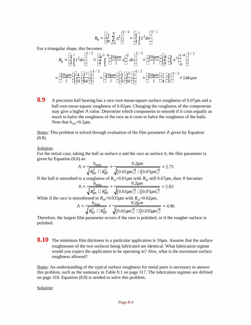
Page 8-4
Rq = 1N
zi2
i=1
N
∑
1 / 2
= 1l
z2dx0
l
∫
1 / 2
For a triangular shape, this becomes
Rq = 1l
z2dx0
l
∫
1 / 2
= 4l
10µml
x
2dx
0
l / 4
∫
1 / 2
= 10µml
4l
13
x3
0
l /4
1 / 2
= 10µml
43l
l3
64
1 / 2
= 10µml
13
l2
16
1 / 2
= 10µml
l4
13
1 / 2= 1.44 µm
8.9 A precision ball bearing has a race root-mean-square surface roughness of 0.07µm and aball root-mean-square roughness of 0.02µm. Changing the roughness of the componentsmay give a higher Λ value. Determine which components to smooth if it costs equally asmuch to halve the roughness of the race as it costs to halve the roughness of the balls.Note that hmin=0.2µm.
Notes: This problem is solved through evaluation of the film parameter Λ given by Equation(8.8).
Solution:For the initial case, taking the ball as surface a and the race as surface b, the film parameter isgiven by Equation (8.8) as:
Λ =hmin
Rqa2 + Rqb
2=
0.2µm
0.02µm( )2 + 0.07µm( )2= 2.75
If the ball is smoothed to a roughness of Rqa=0.01µm with Rqb still 0.07µm, then Λ becomes
Λ =hmin
Rqa2 + Rqb
2=
0.2µm
0.01µm( )2 + 0.07µm( )2= 2.83
While if the race is smoothened to Rqb=0.035µm with Rqa=0.02µm,
Λ =hmin
Rqa2 + Rqb
2=
0.2µm
0.02µm( )2 + 0.035µm( )2= 4.96
Therefore, the largest film parameter occurs if the race is polished, or if the rougher surface ispolished.
8.10 The minimum film thickness in a particular application is 10µm. Assume that the surfaceroughnesses of the two surfaces being lubricated are identical. What lubrication regimewould you expect the application to be operating in? Also, what is the maximum surfaceroughness allowed?
Notes: An understanding of the typical surface roughness for metal parts is necessary to answerthis problem, such as the summary in Table 8.1 on page 317. The lubrication regimes are definedon page 318. Equation (8.8) is needed to solve this problem.
Solution:

Page 8-5
Referring to Table 8.1 on page 317, typical surface roughnesses for machine componentsare usually less than 2µm, except for some extremely large gears. Further, based onmanufacturing processes, a surface roughness around 1 µm is plausible. Therefore, the filmparameter, given by Equation (8.8), will be larger than 5, and therefore is the hydrodynamiclubrication regime. (Note: it is possible, but very unlikely, that the partial lubrication regime maybe the proper one.)
From the definition on page 318, the film parameter must be greater than 5 forhydrodynamic lubrication. Therefore, from Equation (8.8), recognizing the two surfaces have thesame roughness,
Λ = hmin
Rqa2 + Rqb
2( )1 / 2 = hmin
2Rq2( )1 / 2; Rq = hmin
Λ 2= 10µm
5 2= 1.414µm
8.11 Two equally rough surfaces with rms surface roughness Rq are lubricated and loadedtogether. The oil film thickness is such that Λ=2. Find the Λ value if one of the surfaces ispolished so that Rq→0 (i.e., the surface becomes absolutely smooth).
Notes: Equation (8.8) is needed to solve this problem.
Solution:For the first case, Equation (8.8) gives:
Λ1 = hmin
Rqa2 + Rqb
2( )1 / 2= hmin
Rq2 + Rq
2( )1 / 2= hmin
2 Rq2( )1 / 2= 2;
hmin
Rq= 2 2
For the second case,
Λ2 = hmin
Rqa2 + Rqb
2( )1 / 2= hmin
Rq2 + 0( )1 / 2= hmin
Rq2( )1 / 2 = hmin
Rq= 2 2
Or Λ2=2.83. Therefore, the film parameter increases from 2 to 2.83.
8.12 Two lubricated surfaces have rms surface roughnesses Rq of 0.23 and 0.04 µm,respectively. By using a new honing machinery either surface can be made twice assmooth. For good lubrication, which surface roughness is it more important to decrease?
Notes: See problem 8.9.
Solution:The film thickness is determined by geometry and operating conditions, but not roughness in thehydrodynamic regime. Therefore, from Equation (8.8) for the original surfaces,
Λ = hmin
Rqa2 + Rqb
2= hmin
0.23µm( )2 + 0.04µm( )2= 4.28 µm( )−1[ ]hmin
If the 0.23µm surface was smoothened to 0.115µm,
Λ = hmin
Rqa2 + Rqb
2= hmin
0.115µm( )2 + 0.04µm( )2= 8.21 µm( )−1[ ]hmin
while if the 0.04µm surface was smoothened to 0.02µm,

Page 8-6
Λ = hmin
Rqa2 + Rqb
2= hmin
0.23µm( )2 + 0.02µm( )2= 4.33 µm( )−1[ ]hmin
Therefore, it is better to smoothen the rougher surface.
8.13 The absolute viscosity of a fluid at atmospheric conditions is 6 x 10⁻³kgf-s/m
2. Give this
absolute viscosity ina) Reynsb) Poisec) Pound force-seconds per square inchd) Newton-seconds per square meter
Notes: Table 8.2 is useful for solving this problem.
Solution:As discussed on page 320, a reyn is a pound-force second per square inch. Using the
conversions from Table 8.2 on page 320, the viscosity in lbf-s/in2 is
η = 6 ×10⁻³kgf − s / m2( ) 1.422 ×10⁻³ reyn
kgf − s / m2
= 8.532µreyn
In poise, the conversion is as follows:
η = 6 ×10⁻³kgf − s / m2( ) 9.807×10³ cP
kgf − s / m2
= 58.84cP = 0.5884P
A pound force-second per square inch is the same as a reyn, so the viscosity isη=8.532lbf-s/in
2.
In Ns/m2, the conversion is as follows:
η = 6 ×10⁻³kgf − s / m2( ) 9.807cP
kgf − s / m2
= 0.05884Ns / m2
8.14 Given a fluid with an absolute viscosity η between two 1m2 surfaces spaced 1 mm apart,
find how fast the surfaces will move relative to each other if a 10-N force is applied in thedirection of the surfaces when η isa) 0.001Ns/m
2 (water)
b) 0.100 Ns/m2 (a thin oil at room temperature)
c) 10.0Ns/m2 (syrup or cold oil)
d) 108Ns/m2 (asphalt)
Notes: Equation (8.11) is needed to solve this problem.
Solution:From Equation (8.11), the velocity can be calculated as:
η = F / Aub / h
; ub = FhηA
= 10N( ) 0.001m( )η 1m2( ) = 0.01N / m
η
Therefore, the following can be calculated:
η (Ns/m2) ub (m/s)
0.001 10

Page 8-7
0.11010
8
0.10.00110
-10
8.15 For a single ball rolling in a groove determine the following:a) Contact zone dimensionsb) Maximum elastic deformationsc) Maximum pressureThe steel ball has a 10mm diameter and a 4N normal force acting on it. The ball and thegroove have a 200GPa modulus of elasticity and a Poisson’s ratio of 0.3. Assume a6.08mm radius groove in a semi-infinite steel block.
Notes: To solve this problem, calculate the following in order: 1) the radii from Equations (8.15)through (8.18); 2) αr, ke, F and E (Equations (8.19), (8.24), and Table 8.6); 3) E’ (Equation(8.28); 4) Dy and Dx (Equations (8.25) and (8.26)); 5) δmax (Equation (8.27)); 6) pmax (Equation(8.23)).
Solution:A sketch of the ball in the groove is shown below.
Note that the direction the ball rolls is the x-direction, so we can write from the given data thatrax=ray=5mm=0.005m; rbx=∞, rby=-6.08mm=-0.00608m. Therefore, from Equation (8.17),
1Rx
= 1rax
+ 1rbx
= 10.005m
+ 1∞
; Rx = 0.005 m
And from Equation (8.18),1
Ry= 1
ray+ 1
rby= 1
0.005m− 1
0.00608m; Ry = 0.02815m
Therefore, from Equation (8.15),1R
= 1Rx
+ 1Ry
= 10.005m
+ 10.02815m
; R = 0.00425m
From Equation (8.19), the radius ratio is
αr =Ry
Rx= 0.02815m
0.005m= 5.630
Therefore, from Equation (8.24),
ke = αr2/ π = 5.630( )2/ π = 3.00
Note that αr≥1, so F and E are calculated as:
F = π
2+ π
2−1
lnαr = π
2+ π
2−1
ln 5.630( ) = 2.557

Page 8-8
E = 1+
π2
−1
αr=1+
π2
−1
5.630= 1.101
Note from Equation (8.28) that E’ is:
′ E = 2
1−νa2
Ea+ 1−ν b
2
Eb
= 2
1 −ν2
E+ 1−ν 2
E
= E
1 −ν2 = 200GPa
1 − 0.32 = 220GPa
Therefore, the contact dimensions are obtained from Equations (8.25) and (8.26) as:
Dy = 2
6ke2EWRπ ′ E
1 / 3
= 26 3.00( )2 1.101( ) 4N( ) 0.00425m( )
π 220GPa( )
1 / 3
= 2.27× 10⁻⁴ m = 0.227mm
Dx = 2
6EWRπke ′ E
1 / 3
= 26 1.101( ) 4N( ) 0.00425m( )
π 3.00( ) 220GPa( )
1 / 3
= 7.57× 10⁻⁵ m = 0.0757mm
The maximum deformation at the contact center is given by Equation (8.27) as:
δmax = F
9
2ER
W
πke ′ E
2
1 / 3
= 2.557( ) 9
2 1.101( ) 0.00425m( )4N
π 3.00( ) 220GPa( )
2
1 / 3
= 3.91 ×10⁻⁷ m
or δmax=0.391µm. The maximum pressure is given by Equation (8.23) as:
pmax = 6WπDxDy
= 6 4 N( )π 7.57 ×10⁻⁵ m( ) 2.27 ×10⁻⁴ m( ) = 0.445GPa
8.16 A solid cylinder rolls with a load against the inside of an outer cylinder race. The solidcylinder radius is 20mm and the race internal radius is 150mm. The race and the rollerhave the same axial length. What is the radius of a geometrically equivalent cylinder neara plane? The cylinder is made of silicon nitride (E=314GPa, ν=0.26) and the race is madeof stainless steel (E=193 GPa, ν=0.30). If the normal applied load is per unit width is12000N/m, determinea) Contact semiwidthb) Maximum surface stressc) Maximum elastic deformationAlso, indicate what these values would be if the silicon nitride cylinder were replacedwith a stainless steel cylinder.
Notes: The solution is similar to Problem 8.15, but this is a rectangular contact. The radius isobtained from Equation (8.15) after obtaining Rx and Ry from Equations (8.17) and (8.18). Thecontact semiwidth is obtained from Equation (8.29), the surface stress from (8.32), and themaximum deformation from Equation (8.31).
Solution:I. GeometryFor the given geometry, rax=0.020m, rbx=-0.150m, ray=rby=∞. Therefore, from Equations (8.17)and (8.18),
1Rx
= 1rax
+ 1rbx
= 10.020 m
− 10.15m
; Rx = 0.02308m

Page 8-9
1Ry
= 1ray
+ 1rby
= 1∞
− 1∞
; Ry = ∞
Therefore, from Equation (8.15),1R
= 1Rx
+ 1Ry
= 10.02308m
+ 1∞
; R = 0.02308m
II. Silicon Nitride on SteelFrom Equation (8.28),
′ E = 2
1− νa2( )
Ea+
1−ν b2( )
Eb
= 2
1− 0.262
314GPa+ 1− 0.32
207GPa
= 272GPa
The dimensionless load is given by Equation (8.30) as:
′ W = ′ w ′ E Rx
= 12,000 N / m272GPa( ) 0.02308m( ) = 1.912 ×10⁻⁶
so that the semi-contact width can be calculated from (8.29) as
b* = Rx8 ′ W
π
1 / 2
= 0.02308 m( )81 .912×10−6( )
π
1 / 2
= 5.093 ×10⁻⁵ m = 50.93µm
The maximum deformation is, from Equation (8.31),
δmax = 2 ′ W Rx
πln
2π′ W
− 1
=
2 1 . 9 1 2×10⁻⁶( ) 0.02308 m( )π
ln2π
1.912 ×10⁻⁶
−1
= 0.393µm
The maximum pressure is given by Equation (8.32) as:
pmax = ′ E ′ W
2π
1 / 2
= 272GPa( ) 1.912 ×10⁻⁶
2π
1 / 2
= 150MPa
III. Steel on SteelIf a steel cylinder is used instead of silicon nitride, the following equations are changed:
′ E = 2
1− νa2( )
Ea+
1−ν b2( )
Eb
= 2
1 − 0.32
207GPa+ 1− 0.32
207GPa
= 227GPa
′ W = ′ w ′ E Rx
= 12,000 N / m227GPa( ) 0.02308m( ) = 2.290 ×10⁻⁶
b* = Rx8 ′ W
π
1 / 2
= 0.02308 m( )8 2.290× 10⁻⁶( )
π
1 / 2
= 55.73µm
δmax = 2 ′ W Rx
πln
2π′ W
− 1
=
2 2.290 ×10⁻⁶( ) 0.02308 m( )π
ln2π
2.290× 10⁻⁶
−1
= 0.464µm
pmax = ′ E ′ W
2π
1 / 2
= 227GPa( ) 2.290 ×10⁻⁶
2π
1 / 2
= 137MPa
8.17 A 10cm diameter shaft has a 2 cm diameter ball rolling around the outside. Find thecurvature sum, the maximum contact stress, the maximum deflection, and the contactdimensions if the ball load is 1000N. The ball is made of silicon nitride (E=314GPa,

Page 8-10
ν=0.26), and the shaft is made of steel (E=206GPa, ν=0.3). Also determine the values ifboth ball and shaft are made of steel.
Notes: This is similar to Problems 8.15 and 8.16.
Solution:I. GeometryFor the given geometry, rax=ray=0.010m, rbx=0.05m, rby=∞. Therefore, from Equations (8.17) and(8.18),
1Rx
= 1rax
+ 1rbx
= 10.010 m
+ 10.05m
; Rx = 0.00833m
1Ry
= 1ray
+ 1rby
= 10.010m
− 1∞
; Ry = 0.010m
Therefore, from Equation (8.15),1R
= 1Rx
+ 1Ry
= 10.00833m
+ 10.010
; R = 0.00454m
From Equation (8.19),
αr =Ry
Rx= 0.010m
0.00833m=1.2
and from Equation (8.24),ke=αr
2/π=(1.2)
2/π=1.123
Since 1<αr<100, Table 8.6 gives
F = π
2+ π
2−1
lnαr = π
2+ π
2−1
l n 1 . 2( ) = 1.675
E = 1+
π2
−1
αr= 1+
π2
−1
1.2= 1.476
II. Silicon Nitride on SteelFrom Equation (8.28),
′ E = 2
1− νa2( )
Ea+
1−ν b2( )
Eb
= 2
1− 0.262
314GPa+ 1− 0.32
207GPa
= 272GPa
Therefore, the dimensions of the contact are obtained from Equations (8.25) and (8.26):
Dy = 2
6ke2EWRπ ′ E
1 / 3
= 26 1.123( )2 1.476( ) 1000N( ) 0.00454 m( )
π 272GPa( )
1 / 3
= 7.80 ×10⁻⁴ m
Dx = 2
6EWRπke ′ E
1 / 3
= 26 1.476( ) 1000N( ) 0.00454( )
π 1.123( ) 272GPa( )
1 / 3
= 6.95×10⁻⁴ m
The maximum contact pressure can be calculated from Equation (8.23) as:
pmax = 6WπDxDy
= 6 1000N( )π 7.80 ×10⁻⁴m( ) 6.95 ×10⁻⁴m( ) = 3.52GPa
The maximum deflection is obtained from Equation (8.27) as:

Page 8-11
δmax = F
9
2ER
W
πke ′ E
2
1 / 3
= 1.675( ) 9
2 1.476( ) 0.00454m( )1000N
π 1.123( ) 272GPa( )
2
1 / 3
=15.1µm
II. Steel on SteelIf the ball is changed to steel, the following equations are changed:
′ E = 2
1− νa2( )
Ea+
1−ν b2( )
Eb
= 2
1 − 0.32
207GPa+ 1− 0.32
207GPa
= 227GPa
Dy = 2
6ke2EWRπ ′ E
1 / 3
= 26 1.123( )2 1.476( ) 1000N( ) 0.00454 m( )
π 227GPa( )
1 / 3
= 8.28×10⁻⁴ m
Dx = 2
6EWRπke ′ E
1 / 3
= 26 1.476( ) 1000N( ) 0.00454( )
π 1.123( ) 227GPa( )
1 / 3
= 7.38×10⁻⁴ m
pmax = 6WπDxDy
= 6 1 0 0 0N( )π 8.28 ×10⁻⁴m( ) 7.38×10⁻⁴m( ) = 3.13GPa
δmax = F
9
2ER
W
πke ′ E
2
1 / 3
= 1.675( ) 9
2 1.476( ) 0.00454m( )1000N
π 1.123( ) 227GPa( )
2
1 / 3
=17.0µm
8.18 The ball-outer-race contact of a ball bearing has a 17mm ball diameter, an 8.84-mm outerrace groove radius, and a 44.52-mm radius from the bearing axis to the bottom of thegroove. The load on the ball is 25,000N. Calculate the dimensions of the contact ellipseand the maximum deformation at the center of contact. The race and the ball are made ofsteel.
Notes: The problem statement means that rax=8.5mm, rbx=-44.52mm, ray=8.5mm, rby=-8.84mm.Then using Equations (8.15) through (8.21) and *8.25) through (8.27) gives the solution.
Solution:Note that rax=8.5mm, rbx=-44.52mm, ray=8.5mm, rby=-8.84mm. Also, for steel it is known fromthe inside front cover that E=207GPa and ν=0.30. Therefore, from Equation (8.28),
′ E =2
1− νa2
Ea+ 1− ν b
2
Eb
=2
21− ν 2
E
=E
1 − ν2 =207GPa
1 − 0.302 = 227.5GPa
From Equations (8.17) and (8.18):1
Rx=
1
rax+
1
rbx=
1
0.0085m−
1
0.04452m; Rx = 0.0105m
1
Ry=
1
ray+
1
rby=
1
0.0085m−
1
0.00884m; Ry = 0.221m
Therefore, from Equation (8.15),1
R=
1
Rx+
1
Ry=
1
0.0105m+
1
0.221m; R = 0.0100m

Page 8-12
Note that from Equation (8.19) that αr=Ry/Rx=0.221/0.0105=21.035. From Equation (8.24),
ke = αr2/ π = 21.035( )2 /π = 6.954
From Table 8.6 on page 331, and noting that 1<αr<100,
F =
π2
+π2
−1
lnαr =
π2
+π2
−1
ln21.035 = 3.310
E = 1+
π2
−1
αr=1 +
π2
−1
21.035= 1.0271
From Equation (8.25),
Dy = 2
6ke2EWR
π ′ E
1 / 3
= 26 6.954( )2 1.0271( ) 25000N( ) 0.01m( )
π 227.5GPa( )
1 / 3
= 0.00942m = 9.42mm
From Equation (8.20), (Note: Equation (8.26) gives the same answer)
ke =Dy
Dx; Dx =
Dy
ke=
9.42mm
6.954= 1.35mm
Finally, from Equation (8.27), the maximum deflection is
δmax = F
9
2ER
W
πke ′ E
2
1 / 3
= 3.310( ) 9
21.0271( ) 0.01m( )25000N
π 6.954( ) 227.5GPa( )
2
1 / 3
or δmax=73.7µm.
8.19 A rectangular box stands on an inclined plane with the slope angle α. The center ofgravity is in the geometric center of the box, which has a height h and length l. Find the αat which the box starts to slide down.
Notes: This problem required only force equilibrium to be solved. Although this can be done inthe vertical and horizontal directions, it is more easily derived by considering force equilibriumperpendicular and tangent to the surface.
Solution:The free body diagram of the box on the plane is sketched below.
Consider force equilibrium perpendicular to the surface:ΣFy’=0=-magcosα+N=0; N=magcosα
Force equilibrium along the angled surface gives:
Fα = 0 = −magsinα + µN∑ = −mag sinα + µ magcosα( ); µ = magsinαmag cosα
= tan α
Therefore, the block starts to slide as soon as α>tan-1µ.

Page 8-13
8.20 Find the ratio h/l when the box in Problem 8.19 falls over rather than slides down, anddetermine how high the coefficient of friction then has to be.
Notes: This solution uses the results from Problem 8.19.
Solution:For the box to fall over, the vertical gravitational force mag mustbe directed outside the bottom surface of the box. Therefore, thebox falls over if (see sketch):
tan α ≥ l /2ht / 2
= lht
From Problem 8.19, the box will slide if µ<tanα. Therefore, forthe box to tip,
µ > tanα = lht
The box falls over if the ratio ht/l is greater than cotα, but slides (doesn’t tip) if the coefficient offriction is less than tanα.
8.21 A polymer box stands on a slope. The box weighs 10kg and the slope angle is 25°. Topull the box down the slope, a force F=5N is needed. The friction force is proportional tothe load raised to the 0.75. Find the extra weight needed in the box to make it slide downthe slope.
Notes: The non-linear proportionality between friction force and normal load is typical for softpolymers. This solution needs only equilibrium. Consideration of the unloaded (10kg) box allowsdetermination of the proportionality constant between friction and force to the 0.75 power. Usinga load in the box then allows determination of the critical angle.
Solution:Note that the friction relationship is F=CN
0.75, where C is a
constant. A free body diagram of the box is shown.Taking force equilibrium perpendicular to the surface gives:
ΣFp=0=N-magcos25°; N=magcos25°Taking force equilibrium tangent to the surface gives:
F∑ t= 0 = −mags i n 2 5° −F + CN0.75 ; C =
mags i n 2 5° +F
N 0.75
Substituting for N and solving,
C =mags i n 2 5°+ F
mag cos25°( )0.75 =10kg( ) 9.807m / s2( )sin 25°+ 5N
10kg( ) 9.807m / s2( ) cos25°[ ]0.75 =1.60 N / N 0.75
If the weight in the box is unknown, so the weight of the box plus additional material is denotedas W. For the box to slide down the plane, F=0, so that the force equilibrium equations give:
ΣFp=0=N-Wcos25°; N=Wcos25°
F∑ t= 0 = −W s i n 2 5° + 1.6N / N0.75( )N0.75 ; W =
1.6N / N0.75( )N 0.75
sin25°

Page 8-14
Substituting for N gives an equation for W:
W =1.6N / N0.75( ) W cos25°( )0.75
s i n 2 5°; W 0.25 =
1.6 N0.25( ) c o s 2 5°( )0.75
sin25°= 3.52N0.25
Therefore W=153N. Since the box itself weighs (10kg)(9.81m/s2)=98.1N, the extra weight of
material needed is 153N-98.1N=54.9N, or 5.60kg.
8.22 A cross-country skier who waxes the central part of the skis (under the foot) with a high-friction wax can run up a 5.7° slope without slipping backward. The front and the backparts of the skis are waxed with a low-friction wax having a 0.01 coefficient of friction.Determine the downhill slope needed to continue sliding at constant speed.a) If the skier is so light that only the low-friction parts of the skis contact the snow.b) If the skier is so heavy that half the weight is carried by the central part of the skis.
Notes: It was shown in Problem 8.19 that sliding is imminent when µ=tanα, where α is the angleof inclination. This result is used along with force equilibrium to solve this problem.
Solution:For the high friction wax, we can use the results of Problem 8.19 to get the coefficient of frictionas:
µ = tanα = t a n 5 . 7° = 0.100For the light skier, where only the low friction parts of the skis contact the snow, the sameequation predicts the slope where sliding is imminent as:
µ = tanα ; α = tan−1 µ( ) = tan−1 0.01( ) = 0.57°For the heavy skier, the friction force is
F = 0.1( )W
2+ 0.01( )W
2= 0.055W
where W is the weight of the skier. Therefore, the coefficient of friction is µ=F/W=0.055, so thecritical slope is:
µ = tanα ; α = tan−1 µ( ) = tan−1 0.055( ) = 3.15°
8.23 A moose suddenly jumps out onto a dry asphalt road 80m in front of a car running at 108km/hr. The maximum coefficient of friction between the rubber tires and the road is 1.0when they just start to slide and 0.8 when the locked wheels slide along the road. It takes1s for the driver to apply the brakes after the moose jumps onto the road. Find whetherthe car can stop before it hits the moosea) With locked wheels sliding along the roadb) With an automatic braking system (ABS) that keeps the sliding speed so low thatmaximum friction is maintained.
Notes: There are a number of ways of solving this problem. This solution considers the distanceneeded to dissipate the initial kinetic energy through friction.
SolutionThe velocity of the car is v=108km/hr=30m/s. Since it takes one second before the brakes areapplied, the car travels 30m before it begins to slow down. Therefore, the car must be able to stopin 80m-30m=50m in order to avoid hitting the moose. The initial kinetic energy in the car is

Page 8-15
KE =1
2mav2 =
1
2ma 30m / s( )2 = 450m2 / s2( )ma
The energy dissipated in friction is the product of the frictional force and the distance. For adistance of 50m, the energy dissipated for locked wheels is
E=Fd=µmagd=(0.8)ma(9.807m/s2)(50m)=392m
2/s
2ma
This energy is less than the initial kinetic energy in the car. Therefore, the moose is hit. If an ABSsystem is present so that µ=1,
E=Fd=µmagd=(0.8)ma(9.807m/s2)(50m)=490m
2/s
2ma
Since this is greater than the initial kinetic energy in the car, we conclude that the car stops shortof the moose.
8.24 Given a block on an incline as shown in sketch a, find the force requireda) To prevent motion downwardb) To cause motion upwardThe coefficient of friction is 0.30. Draw a free body diagram for both situations showingthe forces involved.
Notes: Because of the direction of the applied force P, it is convenient in this case to performforce equilibrium in the vertical and horizontal directions.
Solution:
I. Prevention of Downward MotionThe free body diagram for this case is as shown. The figurealready has applied the rule that F=µN for the friction force onthe surface. Note that the friction force opposes relative motion.Applying vertical force equilibrium,
Fy = 0 = −600lb + Nc o s 3 5°+ µNsin 35°; N =600 lb
cos35° + 0.3( )sin35°= 605lb∑
Applying horizontal force equilibrium and solving for P gives:Fx = 0 = P − N s i n 3 5°+ µN cos35°∑
P = N sin35° − µc o s 3 5°( ) = 605 lb( ) s i n 3 5°− 0.3cos35°( ) = 198lb
II. Initiation of Upward MotionThe free body diagram is as shown. Note that the friction force,which opposes relative motion, is applied in the oppositedirection as in part I. Applying vertical force equilibrium,
Fy = 0 = −600lb + Nc o s 3 5°− µNsin 35°; N =600 lb
cos35° − 0.3( )sin35°= 927lb∑

Page 8-16
Applying horizontal force equilibrium and solving for P gives:Fx = 0 = P − N sin35° −µN cos35°∑
P = N sin35° + µc o s 3 5°( ) = 927lb( ) sin35° +0 . 3 c o s 3 5°( ) = 760lb
8.25 Three equal blocks of plastic are carrying the weight of a steel slider. At first each blockcarries one-third of the weight, but the central block is made of polytetrafluoroethylene(PTFE) and the outer two blocks are made of polyethylene, so they have differentadhesive wear constants (PTFE, k1=2x10
-5; polyethylene, k1=2x10
-8). Determine how the
load redistributes between the blocks if the hardnesses of the plastics are assumed to bethe same.
Notes: The load redistributes until the wear rate is the same for the two materials. The keyequation is (8.44).
Solution:The load will redistribute until the wear rate is constant. If the wear volume is given by Equation(8.44) as
v = k1WL
3Hthen the wear rate is
∂v
∂t=
∂∂t
k1WL
3H
=
k1W
3H
∂L
∂t=
k1Wu
3Hwhere u is the sliding velocity. For the wear rate of polyethylene (PE) to equal the wear rate ofpolytetrafluoroethylene, (PTFE), and noting HPE=HPTFE=H and u=constant,
k1,PEWPEu
3H=
k1,PTFEWPTFEu
3H;WPE = WPTFE
k1,PTFE
k1,PE= WPTFE
2 × 10⁻⁵
2 × 10−8 = 1000WPTFE
or that the polyethylene carries 1000 times the load of the PTFE.
8.26 Given the plastic blocks in Problem 8.25 and sharing the load so that the wear is equal oneach block, find the coefficient of friction.
Notes: The coefficients of friction for the two materials are obtained from Table 8.8 on page 344.This solution uses the results from Problem 8.25.
Solution:From Table 8.8 on page 344, the coefficient of friction of polyethylene on steel is 0.5, while thecoefficient of friction for polytetrafluoroethylene on steel is 0.2. Recall from Problem 8.25 thatWPE=1000WPTFE. Therefore, the total normal force, which equals the total weight, is
N=2WPE+WPTFE=2001WPTFE
The friction force developed is:F=2(0.5)WPE+(0.2)WPTFE=2(0.5)(1000WPTFE)+0.2WPTFE=1000.2WPTFE
The coefficient of friction is then
µ =F
N=
1000.2WPTFE
2001WPTFE= 0.4999
Note that the polytetrafluoroethylene has a negligible effect on friction because it carries such asmall portion of the load.

Page 8-17
8.27 A 50kg copper piece is placed on a flat copper surface as shown in sketch b. Assume thatcopper has a hardness of 275MPa. Calculate the shear stress, the abrasive wear volume,and the adhesive wear volume.
Notes: Using a coefficient of friction from Table 8.8, the shear stress can be calculated fromEquation (8.39). The adhesive wear volume is calculated from Equation (8.44) while the abrasivewear volume is obtained from Equations (8.45) and (8.46).
Solution:Note from Table 8.8 on page 344 that for copper sliding against copper, µ=1.2 and k1=0.01-0.1.The average value of the adhesive wear constant is 0.055, which will be used in this solution.Note that the problem illustration matches Figure 8.19, with θ=6°. Therefore, Equation (8.39)gives:
µ =τH
+2
πtanθ ; τ = H µ −
2
πtanθ
= 275MPa( ) 1.2 −
2
πtan6°
= 312MPa
Using the value of adhesive wear constant k1=0.055, and using L=7.5m as shown, the adhesivewear volume is obtained from Equation (8.44) as:
v =k1WL
3H=
0.055( ) 50kg( ) 9.807m / s2( ) 7.5m( )3 275MPa( )
= 2.45 ×10⁻⁷m3
The abrasive wear constant (to be used in Equation (8.45)) is obtained from Equation (8.46) as:
k2 =2tan θ
π=
2 t a n 6°π
= 0.0669
Therefore, the abrasive wear volume is (from Equation (8.45)),
vabr =k1k2WL
H=
0.055( ) 0.0669( ) 50kg( ) 9.807m / s2( ) 7.5m( )275MPa
= 4.92 ×10⁻⁸m3
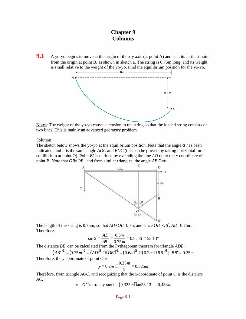
Page 9-1
Chapter 9Columns
9.1 A yo-yo begins to move at the origin of the x-y axis (at point A) and is at its farthest pointfrom the origin at point B, as shown in sketch a. The string is 0.75m long, and its weightis small relative to the weight of the yo-yo. Find the equilibrium position for the yo-yo.
Notes: The weight of the yo-yo causes a tension in the string so that the loaded string consists oftwo lines. This is mainly an advanced geometry problem.
Solution:The sketch below shows the yo-yo at the equilibrium position. Note that the angle α has beenindicated, and it is the same angle AOC and BOC (this can be proven by taking horizontal forceequilibrium at point O). Point B’ is defined by extending the line AO up to the x-coordinate ofpoint B. Note that OB=OB’, and from similar triangles, the angle AB’D=α.
The length of the string is 0.75m, so that AO+OB=0.75, and since OB=OB’, AB’=0.75m.Therefore,
sinα =AD
A ′ B =
0.6m
0.75m= 0.8; α = 53.13°
The distance BB’ can be calculated from the Pythagorean theorem for triangle ADB’:
A ′ B ( )2 = 0.75m( )2 = AD( )2 + D ′ B ( )2 = 0.6m( )2 + 0.2m + B ′ B ( )2 ; B ′ B = 0.25mTherefore, the y coordinate of point O is
y = 0.2m +0.25m
2= 0.325m
Therefore, from triangle AOC, and recognizing that the x-coordinate of point O is the distanceAC,
x = OC tanα = y tanα = 0.325m( ) tan53.13° =0.433m

Page 9-2
9.2 For the yo-yo in Problem 9.1, the central pin has a diameter of 5mm. The outsidediameter of the yo-yo is 50mm, and the diameter of the string is 1mm, which is the sameas the width of the slot of the yo-yo. Will the yo-yo roll from point A to point B iftightened slowly?
Notes: The solution assumes that the yo-yo weight is small enough (or the string is strongenough) so that the string does not break under the tension. This solution uses the solution ofProblem 9.1.
Solution:As the string is shortened, the equilibrium position shifts. The main question is whether or not theyo-yo rolls to A or jumps (i.e., whether or not the equilibrium is stable or unstable). If the string istaught between A and B, its length is lAB=(0.2
2+0.6
2)=0.632m. Therefore, the length varies from
0.75m to 0.632m. Note that the angle α as a function of string length is:
sinα =AD
l=
0.6m
l; α =sin −1 0.6m
l
The length BB’ as a function of string length l is given by:
A ′ B ( )2 = l2 = AD( )2 + D ′ B ( )2 = 0.6m( )2 + 0.2m + B ′ B ( )2 ; B ′ B = l2 − 0.6m( )2 − 0.2mThe y-coordinate as a function of string length is:
y = DB +B ′ B
2= 0.2m +
l2 − 0.6m( )2 − 0.2m
2So that the x-coordinate of the yo-yo (point O) as a function of string length is:
x = y tan α = 0.2m +l2 − 0.6m( )2 − 0.2m
2
tan sin−1 0.6m
l
This is plotted below. Note that the x-coordinate of the yo-yo follows a smooth transition, withoutbifurcations, to point B.

Page 9-3
Alternate Solution:Refer to the sketch given in Problem 9.1. For stable equilibrium,
tan β >2.5 + 0.5
25= 0.12; β > 6.84°
The angle γ is given by
tan γ =0.2
0.6; γ =18 .43°
Since β<γ. we conclude that the yo-yo will roll to point B.
9.3 A person rides a bike on a horizontally flat road. Is this a neutral, stable, or unstableequilibrium position?
Notes: See the text on page 360 for the definitions of neutral, stable and unstable equilibrium.Also, Figure 9.1 depicts these three states.
Solution:This can be answered in two ways, depending on the variable of interest. In terms of position, aflat plane where gravity is the only force field is neutrally stable, as shown in Figure 9.1.In terms of the angle between the bike and the ground it is unstable equilibrium.
9.4 A golf ball is placeda) On top of a small hillb) On a horizontal flat planec) In a shallow grooveFind the type of equilibrium for each condition.
Notes: Refer to Figure 9.1 on page 360.
Solution:a) On top of a small hill is unstable equilibrium, because any infinitesmally small perturbationcauses the ball to roll down the hill.b) On a flat plane is neutral equilibrium, since a small perturbation places the ball in a newequilibrium position.c) In a shallow groove is a stable equilibrium position, since a small perturbation results in theball moving back to the lowest point in the groove.
9.5 A column has pinned ends and is axially loaded in compression. The length is 6m and theweight is 200kg, but the form of the cross section can be changed. The column is made ofsteel (AISI 1040). Find the Euler buckling load fora) A solid circular sectionb) A solid square sectionc) A circular tube with outer diameter of 100mm.d) A square tube with outer dimension of 100mm.

Page 9-4
Notes: The cross sectional area is determined from the weight of the column and the knowndensity of steel. Moments of inertia are found on the inside back cover for the different crosssections. The Euler load is obtained from Equation (9.7).
Solution:From the inside front cover, note that for AISI 1040 steel that E=207GPa and ρ=7850kg/m
3.
From the weight of the column, the area of the cross section can be determined as follows
W = ρV = ρAL; A =W
ρL=
200kg
7850kg / m3( ) 6m( )= 0.00425m2
For both ends pinned, Table 9.1 gives le=l.I. Solid circular section.For the solid circular section, the radius is found from the area as:
A = πr2 ; r =A
π=
0.00425m2
π= 0.0367m
The moment of inertia for a solid circle is (see inside back cover) I=πr4/4=1.44x10
-6m4.
Therefore, Equation (9.7) gives
Pcr =π 2EI
l2 =π2 207GPa( ) 1.44 ×10⁻⁶ m4( )
6m( )2 = 81.7kN
II. Solid square sectionFor the solid square section, the side dimension is calculated from the area as x
2=A; x=0.0652m.
Therefore the moment of inertia is I=x4/12=1.506x10
-6m
4. The Euler load is obtained from
Equation (9.7) as:
Pcr =π 2EI
l2 =π2 207GPa( ) 1.506 × 10⁻⁶m4( )
6m( )2 = 85.5kN
III. Circular TubeIf the outer diameter is 100mm=0.1m, then the inner diameter is calculated from the area as:
A =π4
Do2 − Di
2( ) ; Di = Do2 −
4A
π= 0.1m( )2 −
4 0.00425m2( )π
= 0.0677m
The moment of inertia is then (see inside back cover),
I =π4
ro4 − ri
4( ) =π4
Do
2
4
−Di
2
4
=
π4
0.05m( )4 − 0.0339m( )4( ) = 3.875 × 10⁻⁶m4
So that the Euler load is
Pcr =π 2EI
l2 =π2 207GPa( ) 3.875 ×10⁻⁶m4( )
6m( )2 = 220kN
IV. Square TubeIf the outer dimension is 100mm=0.1m, then the inner dimension is obtained from the area as:
A = xo2 − xi
2; x i = xo2 − A = 0.1m( )2 − 0.00425m2 = 0.0758m
The moment of inertia is then
I =xo
4 − xi4
12=
0.1m( )4 − 0.0758m( )4
12= 5.58 ×10⁻⁶m4
The Euler load is then

Page 9-5
Pcr =π 2EI
l2 =π2 207GPa( ) 5.58 × 10⁻⁶ m4( )
6m( )2 = 317kN
9.6 A column with both ends pinned is 3m long and has a section with an outer diameter of30mm and wall thickness of 5mm. Find which material given in Tables A.1 through A.4gives the highest buckling load. Also, give the buckling loads for AISI 1090 steel,aluminum alloy 2014, and molybdenum.
Notes: The column will be considered to be buckling elastically, since plastic buckling is coveredin later sections. Therefore, Equation (9.7) is used to solve this problem.
Solution:The moment of inertia for the cross section is:
I =π64
do4 − di
4( ) =π64
0.030m( )4 − 0.020m( )4( ) = 3.19× 10⁻⁸ m4
Since we will used Equation (9.7) to obtain the elastic buckling load, the theoretical effectivecolumn length for two pinned ends is, from Table 9.1 on page 366, le=l=3m. Therefore, fromEquation (9.7),
Pcr =π 2EI
l2 =π2 3.19 × 10⁻⁸m4( )
3m( )2 E = 3.50 × 10⁻⁸ m2( )E
Therefore, the material in Tables A.1 through A.4 with the highest elastic modulus will give thelargest buckling load. Reviewing these tables, the material with the highest elastic modulus istitanium carbide.
For AISI 1090 steel, the elastic modulus is E=207GPa. Therefore, the buckling load is:
Pcr = 3.50 ×10⁻⁸m2( )E = 3.50 × 10⁻⁸m2( ) 207GPa( ) = 7245N
For aluminum alloy 2014, E=72GPa, so that the buckling load is:
Pcr = 3.50 ×10⁻⁸m2( )E = 3.50 × 10⁻⁸m2( ) 72GPa( ) = 2520N
For molybdenum, the elastic modulus is E=324GPa, so that
Pcr = 3.50 ×10⁻⁸m2( )E = 3.50 × 10⁻⁸m2( ) 324GPa( ) =11,340 N
9.7 Determine the critical stresses for the four columns considered in Problem 9.5. Let the
column be 8m long and the cross-sectional area be 50cm2. The column material is AISI
1080 steel.
Notes: The critical stress is obtained from Equation (9.10). Otherwise the solution follows theform of Problem 9.5.
Solution:From the inside front cover, note that for AISI 1040 steel that E=207GPa. The area of the crosssection is A=50cm
2=0.005m
2. For both ends pinned, Table 9.1 gives le=l=8m.
I. Solid circular section.For the solid circular section, the radius is found from the area as:

Page 9-6
A = πr2 ; r =A
π=
0.005m2
π= 0.0399m
The moment of inertia for a solid circle is (see inside back cover) I=πr4/4=1.99x10
-6m4.
Therefore, Equation (9.7) gives
Pcr =π 2EI
l2 =π2 207GPa( ) 1.99 ×10⁻⁶ m4( )
8m( )2 = 63.5kN
The critical stress is given by Equation (9.10) as:
σcr =Pcr
A=
63.5kN
0.005m2 = 12.7MPa
II. Solid square sectionFor the solid square section, the side dimension is calculated from the area as x
2=A=0.005m
2;
x=0.0707m. Therefore the moment of inertia is I=x4/12=2.083x10
-6m
4. The Euler load is obtained
from Equation (9.7) as:
Pcr =π 2EI
l2 =π2 207GPa( ) 2.083 ×10⁻⁶m4( )
8m( )2 = 66.5 kN
The critical stress is given by Equation (9.10) as:
σcr =Pcr
A=
66.5kN
0.005m2 = 13.3MPa
III. Circular TubeIf the outer diameter is 100mm=0.1m, then the inner diameter is calculated from the area as:
A =π4
Do2 − Di
2( ) ; Di = Do2 −
4A
π= 0.1m( )2 −
4 0.005m2( )π
= 0.0603m
The moment of inertia is then (see inside back cover),
I =π4
ro4 − ri
4( ) =π4
Do
2
4
−Di
2
4
=
π4
0.05m( )4 − 0.0301m( )4( ) = 4.261× 10⁻⁶m4
So that the Euler load is
Pcr =π 2EI
l2 =π2 207GPa( ) 4.261 ×10⁻⁶m4( )
8m( )2 = 136kN
The critical stress is given by Equation (9.10) as:
σcr =Pcr
A=
136kN
0.005m2 = 27.2 MPa
IV. Square TubeIf the outer dimension is 100mm=0.1m, then the inner dimension is obtained from the area as:
A = xo2 − xi
2; x i = xo2 − A = 0.1m( )2 − 0.005m2 = 0.0707m
The moment of inertia is then
I =xo
4 − xi4
12=
0.1m( )4 − 0.0707m( )4
12= 6.25 ×10⁻⁶m4
The Euler load is then
Pcr =π 2EI
l2 =π2 207GPa( ) 6.25 × 10⁻⁶ m4( )
8m( )2 = 200kN
The critical stress is given by Equation (9.10) as:
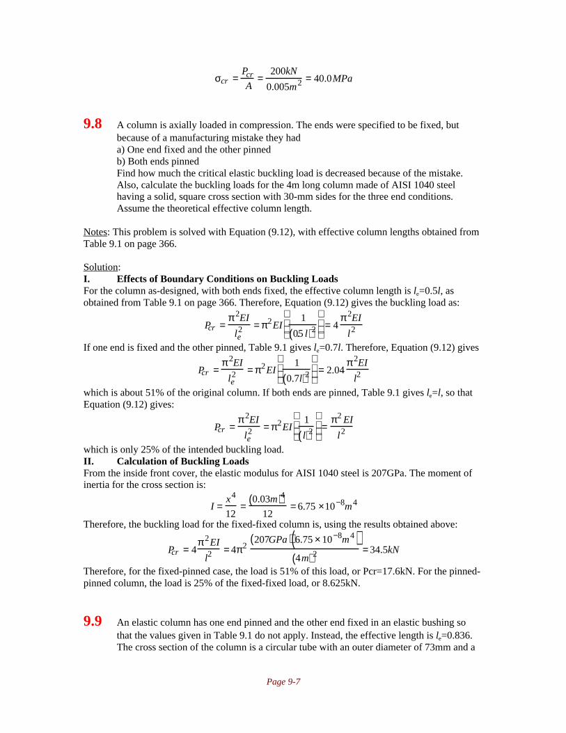
Page 9-7
σcr =Pcr
A=
200kN
0.005m2 = 40.0MPa
9.8 A column is axially loaded in compression. The ends were specified to be fixed, butbecause of a manufacturing mistake they hada) One end fixed and the other pinnedb) Both ends pinnedFind how much the critical elastic buckling load is decreased because of the mistake.Also, calculate the buckling loads for the 4m long column made of AISI 1040 steelhaving a solid, square cross section with 30-mm sides for the three end conditions.Assume the theoretical effective column length.
Notes: This problem is solved with Equation (9.12), with effective column lengths obtained fromTable 9.1 on page 366.
Solution:I. Effects of Boundary Conditions on Buckling LoadsFor the column as-designed, with both ends fixed, the effective column length is le=0.5l, asobtained from Table 9.1 on page 366. Therefore, Equation (9.12) gives the buckling load as:
Pcr =π 2EI
le2 = π2EI
1
0.5 l( )2
= 4
π 2EI
l2
If one end is fixed and the other pinned, Table 9.1 gives le=0.7l. Therefore, Equation (9.12) gives
Pcr =π 2EI
le2 = π2EI
1
0.7l( )2
= 2.04
π 2EI
l2
which is about 51% of the original column. If both ends are pinned, Table 9.1 gives le=l, so thatEquation (9.12) gives:
Pcr =π 2EI
le2 = π2EI
1
l( )2
=
π2 EI
l2
which is only 25% of the intended buckling load.II. Calculation of Buckling LoadsFrom the inside front cover, the elastic modulus for AISI 1040 steel is 207GPa. The moment ofinertia for the cross section is:
I =x4
12=
0.03m( )412
= 6.75 ×10⁻⁸m4
Therefore, the buckling load for the fixed-fixed column is, using the results obtained above:
Pcr = 4π 2EI
l2= 4π2
207GPa( ) 6.75 × 10⁻⁸m4( )4m( )2 = 34.5kN
Therefore, for the fixed-pinned case, the load is 51% of this load, or Pcr=17.6kN. For the pinned-pinned column, the load is 25% of the fixed-fixed load, or 8.625kN.
9.9 An elastic column has one end pinned and the other end fixed in an elastic bushing sothat the values given in Table 9.1 do not apply. Instead, the effective length is le=0.836.The cross section of the column is a circular tube with an outer diameter of 73mm and a

Page 9-8
3.2 mm wall thickness. The column is 11.2 m long. Calculate the elastic buckling load ifthe column is made ofa) AISI 1080 steelb) Polycarbonate
Notes: The buckling load is calculated from Equation Equation (9.12).
Solution:The moment of inertia for the cross section is:
I =π4
ro4 − ri
4( ) =π4
0.0365m( )4 − 0.0333m( )4( ) = 4.28× 10⁻⁷ m4
From the inside front cover, the elastic modulus for AISI 1080 steel is E=207 GPa, so the elasticbuckling load is calculated from Equation (9.12) as:
Pcr =π 2EI
L2 =π2 207GPa( ) 4.28 ×10⁻⁷ m4( )
0.83( ) 11.2m( )[ ]2 = 10.1kN
For polycarbonate, E=2.38 GPa (from Table A.4 on page 902) so
Pcr =π 2EI
L2 =π2 2.38GPa( ) 4.28× 10⁻⁷ m4( )
0.83( ) 11.2m( )[ ]2 =116N
9.10 An elastic AISI 1020 steel column has both ends pinned. It is 12.5m long and has asquare tubular cross section with an outside dimension of 160mm and 4-mm wallthickness. Its compressive axial load is 130kN.a) Determine the safety factor guarding against buckling and yielding.b) If the ends are changed to fixed and the material is changed to aluminum alloy 2014,calculate the safety factors guarding against buckling and yielding.
Notes: Equation (9.12) is used to obtain the buckling load. The safety factor against buckling isthe ratio of the allowable stress to the applied stress, but since the area is constant, this is also theratio of allowable load to applied load. The safety factor against yielding is the ratio of allowablestress to the applied stress.
Solution:For this cross section the area and moment of inertia are:
A = x2 − x − 8mm( )2 = 0.160 m( )2 − 0.152m( )2 = 0.002496 m2
I =1
12x4 − x − 8mm( )4( ) =
1
120.160m( )4 − 0.152 m( )4( ) = 1.013 × 10⁻⁵m4
I. AISI 1020 Steel ColumnFor AISI 1020 steel, the inside front cover gives E=207GPa and Sy=295MPa. With both endspinned, Table 9.1 gives le=l=12.5m. Therefore, Equation (9.12) gives the allowable elasticbuckling load as:
Pcr =π 2EI
L2 =π2 207GPa( ) 1.013 ×10⁻⁵m4( )
12.5m( )2 = 132.5kN
The safety factor against elastic buckling is (see Equation (1.1)):
ns =σall
σd=
Pcr / A( )P / A( )
=Pcr
P=
132.5kN
130kN= 1.02

Page 9-9
Against yielding the safety factor is
ns =σall
σd=
Sy
P / A( )=
ASy
P=
0.002496m2( ) 295MPa( )130kN
= 5.66
II. Aluminum 2014 ColumnFor aluminum 2014, the elastic modulus and yield strength are obtained from the inside frontcover as E=72GPa and Sy=97MPa. If both ends are fixed, then from Table 9.1, le=0.5l=6.25m.Therefore, Equation (9.12) gives the allowable elastic buckling load as:
Pcr =π 2EI
L2 =π2 72GPa( ) 1.013 ×10⁻⁵ m4( )
6.25m( )2= 184.3kN
The safety factor against elastic buckling is (see Equation (1.1)):
ns =σall
σd=
Pcr / A( )P / A( )
=Pcr
P=
184.3kN
130kN=1.42
Against yielding the safety factor is
ns =σall
σd=
Sy
P / A( )=
ASy
P=
0.002496m2( ) 97MPa( )130kN
=1.86
9.11 A beam has both ends mounted in stiff rubber bushings giving bending moments in thebeam ends proportional to the angular displacement of the beam ends. Calculate theeffective beam length if the angular spring constant at the ends is ∂M/∂θ=105Nm/radianin all directions. The beam is 3m long and has a solid circular cross section of AISI 1080steel with a 24mm diameter.
Notes: This problem is solved by using Equation (9.2) and resolving for the critical load using thesame approach as on page 363, but with different boundary conditions. The effective length isobtained from Equation (9.12) once the critical load is obtained.
Solution:From Equation (9.2) and differentiating,
dy
dx= θ = C1
P
EIcos x
P
EI
− C2
P
EIsin x
P
EI
The boundary conditions are that y=0 at x=0 and θ=0 at x=l/2-x0. The first boundary conditiongives C2=0. The second gives:
0 = C1P
EIcos
l
2− x0
P
EI
;
l
2− x0
P
EI= ±
π2
; x0 =l
2−
π2
EI
P
From Equation (5.3), the bending moments at the loading points are:
M = − 105 Nm / rad( ) dy
dx= −EI
d2y
dx2
where d2y/dx
2 is
d2y
dx 2 =d
dx
dy
dx
=
d
dxC1
P
EIcos x
P
EI
= −C1
P
EIsin x
P
EI
Therefore, the moment equation becomes

Page 9-10
105 Nm / rad( )C1P
EIcos x
P
EI
= −C1
P
EIsin −x0( ) P
EI
; t a nx0
P
EI
=
105 Nm / rad
P / EI
Solving this expression numerically gives Pcr=14,145N.The effective length is obtained from Equation (9.12) as:
Pcr =π 2EI
le2 ; le = π
EI
Pcr= π
207GPa( )π 0.024m( )4 /64
14,145N= 1.534m
9.12 Two circular columns are made of different materials, steel and aluminum. The cross-sectional areas are the same and the moduli of elasticity are 207GPa for the steel and72GPa for the aluminum. Find the ratio of the critical buckling lengths for the steel andaluminum columns while assuming that the same buckling load is applied to bothcolumns.
Notes: Equation (9.10) is used to solve this problem.
Solution:For the same buckling load, Equation (9.10) gives:
Pcr =π 2EI
le2 ;
π 2EaI
lea2 =
π 2EsI
les2 ;
les
lea=
Es
Ea=
207GPa
72GPa=1.696
9.13 A television mast shown in sketch b consists of a circular tube with an outer diameter do
and a wall thickness th. Calculate how long the distance l between the anchoring pointsfor the cables can be if the television mast should deform plastically rather than buckle.
Notes: The purpose of the anchoring points is to force a higher buckling mode. This is a commondesign approach for lattice structures such as booms and scaffolding. This problem is solved bypreserving the n from Equation (9.6) in the derivation of Equation (9.10).
Solution:For this cross section, the area and moment of inertia are:
A =π4
do2 − di
2( )

Page 9-11
I =π64
do4 − di
4( ) =π64
do2 − di
2( ) do2 + di
2( )The anchoring points with the cables as shown force the column into a higher buckling mode.The given geometry uses n=3. Therefore, from Equation (9.6),
P =n2π 2EI
l2
If the mast deforms plastically, thenP
A= Sy ; P = ASy
Substituting and solving for l gives:
ASy =n2π 2EI
3l( )2 ; l =1
3
n2π2EI
ASy=
πn
3
Eπ64
do2 − di
2( ) do2 + di
2( )
π4
do2 − di
2( )Sy
=π4
E do2 + di
2( )Sy
or, substituting for di,
l =π4
E do2 + do − 2th( )2( )
Sy=
π4
2E do2 − 2do th + 2 th
2( )Sy
9.14 A 3m long column of square, solid cross section with both ends fixed must sustain a
critical load of 3x10⁵N. The material is steel with a modulus of elasticity of 207GPA and
a yield stress of 700MPa. Determine the following:a) What minimum dimensions of a square, solid cross section are permitted withouthaving failure? Should the Euler or Johnson equation be used?b) If the critical load is increased by two orders of magnitude (Pcr=3 x 10
7N), what
minimum dimensions of a square, solid cross section are permitted without havingfailure? Also, indicate whether the Euler or Johnson equation should be used.
Notes: Equation (9.18) gives the critical column length. If le/rg from Euler analysis (Equation(9.15) is greater than this value, the column is elastic. Otherwise, the column buckles plasticallyand the Johnson equation (9.16) should be used. This problem specifies use of either the Euler orJohnson equation, so the AISC recommended lengths from Table 9.1 are not used.
Solution:(a) The critical column length for this material is given by Equation (9.18) as:
lerg
T
=2π2E
Sy=
2π2 207GPa( )700MPa( )
= 76.40
From Equation (4.13), for a square cross section, the radius of gyration is
rg =I
A=
w4
12w2 =w
2 3For both ends fixed, Table 9.1 gives le=0.5l=1.5m. Assume the buckling is elastic, so that theEuler equation should be used. Then from Eq. (9.15),
lerg
E
=π 2EA
Pcr;
1.5m( )2 3
w=
π2 207GPa( )w2
3× 10⁵ N; w = 0.045m

Page 9-12
Therefore, rg=0.013m, and le/rg is 115. Since this is greater than the critical column length,buckling is elastic and the minimum dimension is 45 mm.(b) If the buckling load is 3 x 10
7 N, again assuming the Euler equation holds,
lerg
E
=π 2EA
Pcr;
1.5m( )2 3
w=
π2 207GPa( )w2
3× 10⁷ N; w = 0.140m
Then rg=.040m, le/rg=38. Since this is less than the critical aspect ratio, the column is plastic andthe Johnson equation should be used. Therefore, from Eq. (9.16):
σcr =Pcr
w2 = Sy −Sy
2
4π 2E
lerg
2
; w = 0.220m
9.15 A solid, round column with a length of 2m and a diameter of 50mm is fixed at one endand free at the other end. The material’s yield strength is 300MPa and its modulus ofelasticity is 207GPa. Assume concentric loading of the column. Determine the following:a) The critical load on this column.b) The critical load on the column if the free end is also fixed (i.e. both ends are fixed).
Notes: This problem asks for determination of a column’s critical load, so either the Euler orJohnson equations are used for solution of this problem. The AISC requirements would be usedfor a case where the design load for a column has been stated and the goal is to design a columnthat will support this load without buckling.
Solution:For this solid round column, the cross sectional area is A=πr
2=π(0.05m/2)
2=0.00196m
2. The
moment of inertia is (see inside back cover) I=πr4/4=π(0.05m/2)
4/4=0.3068x10
-6m
4. The radius of
gyration is calculated from Equation (4.14) as
rg =I
A=
0.3068 × 10⁻⁶m4
0.00196m2 = 0.0125m
I. Free-Fixed ColumnTable (9.1) gives the theoretical effective column length as le=2l=2(2m)=4m. Therefore,
the slenderness ratio for the column is C=le/rg=4m/0.0125m=320. The critical slenderness ratio isobtained from Equation (9.15) as
Cc =2Eπ2
Sy=
2 207GPa( )π 2
300MPa= 116.7
Since the slenderness ratio of the column exceeds the critical slenderness ratio, the columnbuckles elastically, and the Euler equation (9.7) can be used:
Pcr =π 2EI
l2 =π2 207GPa( ) 0.3068 × 10⁻⁶ m4( )
4m( )2 = 39.2kN
II. Fixed-Fixed ColumnFor this case, Table (9.1) gives the effective column length as le=0.5l=0.5(2m)=1m.
Therefore, the slenderness ratio for this columns is C=le/rg=1m/0.0277m=36.1. Since this is lessthan the critical slenderness ratio, the column buckles plastically and the Johnson equation mustbe used (Equation 9.16). The buckling force is then:

Page 9-13
Pcr = σcrJA = Sy −
Sy2
4π2 E
lerg
2
A[ ] = 300MPa −300MPa( )2
4π 2 207GPa( )80( )2
0.00196m2( ) = 450kN
9.16 A circular cross section bar with a diameter of 2 in and a length of 40 in is axially loaded.The bar is made of medium carbon steel. Both ends are pinned. Determinea) Whether the Johnson or Euler formula should be usedb) The critical load
Notes: The approach is similar to Problem 9.15. This problem asks for determination of acolumn’s critical load, so either the Euler or Johnson equations are used for solution of thisproblem. The AISC requirements would be used for a case where the design load for a columnhas been stated and the goal is to design a column that will support this load without buckling.
Solution:For medium carbon steel, the inside front cover gives for AISI 1040 steel, E=30Mpsi andSy=51ksi. Therefore, from Equation (9.18),
lerg
T
=2π2E
Sy=
2π2 30Mpsi( )51ksi
=108
The area and moment of inertia are:
A =π4
d2 =π4
2in( )2 = 3.14in2
I =π64
d4 =π64
2in( )4 = 0.7854in4
Therefore, the radius of gyration is obtained from Equation (4.13),
rg =I
A=
0.7854in4
3.14in2 = 0.500in
From Table 9.1, for pinned ends, le=l. Therefore, the slenderness ratio for this column islerg
=40 in
0.5 in= 80
Since this is less than the critical slenderness ratio of 108, the column will buckle plastically, andthe Johnson equation (Equation 9.16) must be used. Therefore,
Pcr
A= Sy −
Sy2
4π 2E
lerg
2
= 51ksi −51ksi( )2
4π 2 30Mpsi( )40in
0.5 in
2
= 36.9ksi
Since the area was calculated as 3.14in2, the critical load is Pcr=(3.14in
2)(36.9ksi)=116kip.

Page 9-14
9.17 A low-carbon steel pipe, as shown in sketch c, has an outerdiameter of 2in and a thickness of 0.5in. If it is held in place by aguy wire, determine the largest horizontal force P that can be appliedwithout causing the pipe to buckle. Assume that the ends of the pipeare pin connected
Notes: This problem is similar to the previous problems, but theaxial compressive load must be determined from statics.
Solution:I. Column AnalysisFrom the inside front cover for low carbon steel (AISI 1020),Sy=43ksi and E=30Mpsi. Therefore, Equation (9.18) gives
lerg
T
= 2π2ESy
=2π2 30Mpsi( )
43ksi=117
For this cross section, the area and moment of inertia are:
A = π4
do2 − di
2( ) = π4
2in( )2 − 1in( )2( ) = 2.356in2
I = π64
do4 − di
4( ) = π64
2in( )4 − 1in( )4( ) = 0.7363in4
Therefore, the radius of gyration is obtained from Equation (4.13),
rg = IA
= 0.7363in4
2.356in2 = 0.5590 in
From Table 9.1, le=l=144in. Therefore,lerg
= 144in0.5590 in
= 257.6
Since this is larger than the critical slenderness ratio, the buckling is elastic and the Euler formula(Equation (9.13)) will be used.II. StaticsThe sketch shows a section at the top of the column. The load F is thecompressive buckling load, the force T is the tension in the guy wire, and theforce P is the applied load. Taking horizontal force equilibrium gives
Fx = 0 =∑ 513
T − P; T = 135
P
From vertical force equilibrium,
Fy = 0 =∑ F − 1213
T = F − 1213
135
P
; F = 12
5P
III. Determination of Maximum LoadFrom Equation (9.13), the stress at buckling is:
σcr = π 2E
le / rg( )2=
π2 30Mpsi( )257.6( )2
= 4460 psi
Therefore, the maximum value of F is:
F = σ crA = 4460 psi( ) 2.356in2( ) =10.5kip

Page 9-15
Therefore, the largest value of P is:
F = 125
P; P = 512
F = 512
10.5kip( ) = 4.38kip
9.18 A 20-mm diameter, medium carbon steel (AISI 1040) rod is loaded as a column withrounded ends. The critical load is 110kN. How long can the rod be and still carry thefollowing percentages of the critical load: a) 90%, b) 50%, and c) 2%? Also, indicatewhether the Johnson or Euler equation should be used.
Notes: The approach is similar to problems (9.14) to (9.17). For elastic buckling, the Eulerequation (9.13) is used. For plastic buckling, the Johnson equation (9.16) is used. Selecting whichequation is used depends on the slenderness ratio of the column compared to the criticalslenderness ratio (Equation (9.18)).
Solution:I. Column AnalysisFrom the inside front cover for AISI 1040 steel, E=207GPa and Sy=350MPa. Therefore, fromEquation (9.18),
lerg
T
= 2π2ESy
= 2π2 207GPa( )350MPa
=108
The area and moment of inertia are:
A = π4
d2 = π4
0.02m( )2 = 3.14 ×10⁻⁴m2
I = π64
d4 = π64
0.02m( )4 = 7.854× 10⁻⁹ m4
Therefore, the radius of gyration is obtained from Equation (4.13),
rg = IA
= 7.854× 10⁻⁹ m4
3.14 ×10⁻⁴ m2 = 0.00500m
From Table 9.1, for rounded or pinned ends, le=l.II. 90% of Critical LoadFor this case, the load that can be carried is (0.90)(110kN)=99kN. Assume that the buckling iselastic. From Equation (9.13),
σcr = Pcr
A= π2E
le / rg( )2 ; lerg
=
π 2EAPcr
=π 2 207GPa( ) 3.14 ×10⁻⁴ m2( )
99kN= 80.5
Since this is less than the critical slenderness ratio, the column does not buckle elastically, and theJohnson equation should be used. From Equation (9.16),
PcrA
= Sy −Sy
2
4π 2E
lerg
2
;lerg
= 4π2 E
Sy2 Sy − Pcr
A
= 4π 2 207GPa( )350MPa( )2 350MPa − 99kN
3.142 ×10⁻⁴ m2
= 48.2
Therefore, the maximum column length islerg
= 48.2; le = 48.2rg = 48.2 0.005m( ) = 0.241m

Page 9-16
III. 50% of Critical LoadFor this case, the load that can be carried is (0.50)(110kN)=55kN. Assume that the buckling iselastic. From Equation (9.13),
σcr = Pcr
A= π2E
le / rg( )2 ; lerg
=
π 2EAPcr
=π 2 207GPa( ) 3.14 ×10⁻⁴ m2( )
55kN=108
This is very close to the critical slenderness ratio, and the buckling mode can be taken as eitherelastic or plastic to get the same answer. Since the slenderness ratio of the column is 108 toachieve 55kN, the column length is
lerg
=108;le = 108 rg( ) = 108 0.00500m( ) = 0.540m
IV. 2% of Critical LoadFor this case, the load that can be carried is (0.02)(110kN)=2.2kN. Assume that the buckling iselastic. From Equation (9.13),
σcr = Pcr
A= π2E
le / rg( )2 ; lerg
=
π 2EAPcr
=π 2 207GPa( ) 3.14 ×10⁻⁴ m2( )
2.2kN= 540
This is larger than the critical slenderness ratio, so the column buckles elastically. Since theslenderness ratio of the column is 540 to achieve 2.2kN, the column length is
lerg
=108;le = 540 rg( ) = 540 0.00500m( ) = 2.7m
9.19 Most types of steel have similar moduli of elasticity but can have widely different yieldstrength properties depending on the alloying and the heat treatment. For a columnhaving a solid circular cross section with a diameter of 20mm, the yield strengths forthree steels are 300, 600, and 1000MPa. Find for each steel the critical column lengthwhere buckling would not be a problem.
Notes: The critical slenderness ratio is given in Equation (9.15).
Solution:The area and moment of inertia are:
A = π4
d2 = π4
0.02m( )2 = 3.14 ×10⁻⁴m2
I = π64
d4 = π64
0.02m( )4 = 7.854× 10⁻⁹ m4
Therefore, the radius of gyration is obtained from Equation (4.13),
rg = IA
= 7.854× 10⁻⁹ m4
3.14 ×10⁻⁴ m2 = 0.00500m
The critical length can be obtained from Equation (9.18):
le = rg2π 2E
Sy= 0.5 ×10⁻² m( ) 2π2 207GPa( )
Sy
If Sy=300MPa, this becomes:
le = 0.5 ×10⁻² m( ) 2π2 207GPa( )300MPa
= 0.5835m
For Sy=600MPa,

Page 9-17
le = 0.5 ×10⁻² m( ) 2π2 207GPa( )600MPa
= 0.4126m
For Sy=1000MPa,
le = 0.5 ×10⁻² m( ) 2π2 207GPa( )1000MPa
= 0.3196m
9.20 For a fixed cross sectional area of a steel column, find the geometry that would give thelargest buckling load. The minimum column wall thickness is 5mm
Solution:From Equation (9.12), the buckling load is:
Pcr = π 2EI
le2
The largest critical load is one which maximizes the moment of inertia. Example 9.3 showed thata hollow circular area gives the largest moment of inertia and therefore the largest buckling loads.
Note, however, that boundary conditions can affect the optimum cross section. Forexample, if a column is pinned in one direction but fixed in the perpendicular direction, bucklingis more likely in the pinned direction. A circle would no longer be the best geometry. Theextreme case is when the boundary conditions preclude buckling in one direction, in which case,the optimum geometry is an ideal I-beam, with all of the material in the flanges and zero web.
9.21 A rectangular cross section tube is axially loaded in compression. The tube outsidedimensions are 70 and 90mm. The tube is 2.5m long, and both ends are pinned. The wallthickness is 9mm. Find which of the steels in Appendix A.1 should be used so that plasticbuckling is not a problem.
Notes: Equation (9.18) is used to obtain a material property requirement in order to avoid plasticbuckling. The materials in Appendix A.1 are then evaluated with respect to this property.
Solution:The cross section will buckle across the axis that minimizes the buckling load, so it will naturallybuckle along the axis that minimizes the moment of inertia. For the rectangular shape, this occurswhen the smaller dimension is the height of the cross section. Therefore, use ht=0.070m andb=0.090m. The area and moment of inertia for the cross section are:
A = bht − b − 2t( ) h − 2t( ) = 0.07m( ) 0.09m( ) − 0.052m( ) 0.072m( ) = 0.002556m2
I =1
12bht
3( ) − b − 2 t( ) ht − 2t( )3[ ] =1
120.090m( ) 0.07m( )3 − 0.072m( ) 0.052m( )3[ ] =1.729 ×10⁻⁶ m4
Therefore the radius of gyration is obtained from Equation (4.13) as:
rg =I
A=
1.729 ×10⁻⁶ m4
0.002556m2 = 0.0260m
From Equation (9.18),
lerg
=2π 2E
Sy;
E
Sy=
1
2π2lerg
2
=1
2π 22.5m
0.0260m
2
= 468

Page 9-18
Note that this is a maximum value for E/Sy; larger values would indicate the column is shorterthan the critical length needed to avoid plastic buckling. Therefore, a material with a value ofE/Sy>468 would buckle plastically. Using the material properties in Table A.1, the following tablecan be constructed:Material E (GPa) Sy (MPa) E/Sy
IronNodular cast ironMalleable cast ironAISI 1020AISI 1040AISI 1080Ferritic SSAustenitic SSMartensitic SS
207165172207207207200193200
130275220295350380345207275
1592600782702591548578932727
Therefore, none of the materials in Appendix A.1 will buckle elastically for the given column.
9.22 The column considered in Problem 9.21 is made of AISI 1020 steel. Find the criticalbuckling load.
Notes: This solution relies upon the solution for Problem 9.21. Problem 9.21 showed that thismaterial buckles plastically. Therefore, the Johnson equation will be used without the usualcalculations to determine if the buckling mode is elastic or plastic.
Solution:From the solution to Problem 9.21, A=0.002556m
2, I=1.729x10
-6m
4, rg=0.0260m, and le=2.5m.
From the inside front cover for AISI 1020 steel, E=207GPa and Sy=295MPa. It was shown inProblem 9.21 that the column buckles plastically. Therefore, from Equation (9.16),
Pcr
A= Sy −
Sy2
4π 2E
lerg
2
= 295MPa( ) −295MPa( )2
4π 2 207GPa( )2.5m
0.026m
2
= 196.5MPa
Since the area is 0.002556m2, the critical load is Pcr=(0.002556m
2)(196.5MPa)=502kN.
9.23 A 2.5m long column with one end fixed and one end free is made of aluminum alloy2014 and has a solid, round cross section. Determine the diameter of the column for thefollowing loads:a) P=500kNb) P=800kN
Notes: This problem uses a similar approach to the previous problems. For elastic buckling, theEuler equation (9.13) is used. For plastic buckling, the Johnson equation (9.16) is used. Selectingwhich equation is used depends on the slenderness ratio of the column compared to the criticalslenderness ratio (Equation (9.18)).
Solution:From the inside front cover for aluminum alloy 2014, E=72GPa and Sy=97MPa. Note from Table9.1 that for one end fixed and the other free, le=2l=2(2.5m)=5m. The critical slenderness ratio isobtained from Equation (9.15) as
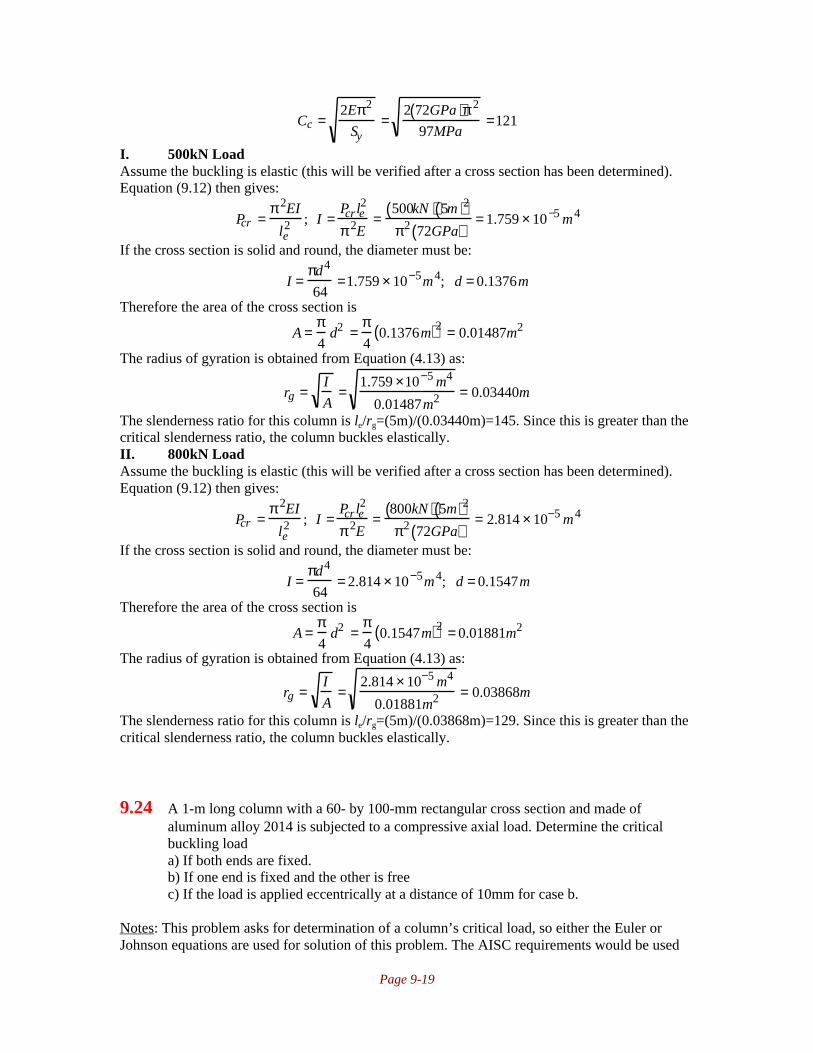
Page 9-19
Cc =2Eπ2
Sy=
2 72GPa( )π 2
97MPa=121
I. 500kN LoadAssume the buckling is elastic (this will be verified after a cross section has been determined).Equation (9.12) then gives:
Pcr =π 2EI
le2 ; I =
Pcr le2
π 2E=
500kN( ) 5m( )2
π2 72GPa( )= 1.759 × 10⁻⁵ m4
If the cross section is solid and round, the diameter must be:
I =πd4
64=1.759 × 10⁻⁵m4; d = 0.1376m
Therefore the area of the cross section is
A =π4
d2 =π4
0.1376m( )2 = 0.01487m2
The radius of gyration is obtained from Equation (4.13) as:
rg =I
A=
1.759 ×10⁻⁵ m4
0.01487m2 = 0.03440m
The slenderness ratio for this column is le/rg=(5m)/(0.03440m)=145. Since this is greater than thecritical slenderness ratio, the column buckles elastically.II. 800kN LoadAssume the buckling is elastic (this will be verified after a cross section has been determined).Equation (9.12) then gives:
Pcr =π 2EI
le2 ; I =
Pcr le2
π 2E=
800kN( ) 5m( )2
π2 72GPa( )= 2.814 × 10⁻⁵ m4
If the cross section is solid and round, the diameter must be:
I =πd4
64= 2.814 × 10⁻⁵m4; d = 0.1547m
Therefore the area of the cross section is
A =π4
d2 =π4
0.1547m( )2 = 0.01881m2
The radius of gyration is obtained from Equation (4.13) as:
rg =I
A=
2.814 × 10⁻⁵ m4
0.01881m2 = 0.03868m
The slenderness ratio for this column is le/rg=(5m)/(0.03868m)=129. Since this is greater than thecritical slenderness ratio, the column buckles elastically.
9.24 A 1-m long column with a 60- by 100-mm rectangular cross section and made ofaluminum alloy 2014 is subjected to a compressive axial load. Determine the criticalbuckling loada) If both ends are fixed.b) If one end is fixed and the other is freec) If the load is applied eccentrically at a distance of 10mm for case b.
Notes: This problem asks for determination of a column’s critical load, so either the Euler orJohnson equations are used for solution of this problem. The AISC requirements would be used

Page 9-20
for a case where the design load for a column has been stated and the goal is to design a columnthat will support this load without buckling. For this homework only, either approach isacceptable. For the eccentric loading, the critical column load is determined by numericallysolving Equation (9.33)
Solution:Note that for Al-2014, the inside front cover gives the values E=72GPa and Sy=97MPa.Therefore, the critical slenderness ratio is, from Equation (9.15),
Cc =2Eπ2
Sy=
2 72GPa( )π 2
97MPa=121
The cross sectional area is A=(0.06m)(0.10m)=0.006m2. The moment of inertia is (see inside back
cover) I=bh3/12=(0.1m)(0.06m)
3/12=1.80x10
-6m
4. (Note that we use h=0.06 so that the moment of
inertia is minimized; the column will buckle on this axis before it buckles on the axis where theheight is 0.1m. This can be easily demonstrated with a yard or meter long ruler.) The radius ofgyration is then obtained from Equation (4.14) as
rg =I
A=
1.80 ×10⁻⁶m4
0.006m2 = 0.0173m
I. Fixed-Fixed ColumnFor this case, Table 9.1 gives le=0.5l=0.5(1m)=0.5m. Therefore, the slenderness ratio for thiscolumn is C=le/rg=0.5m/0.0173m=28.9. Since this is below the critical slenderness ratio, thecolumn buckles plastically and the Johnson equation (Equation 9.16) is used. The buckling forceis then:
Pcr = σcrJA = Sy −Sy
2
4π 2E
lerg
2
A[ ]= 97MPa −97MPa( )2
4π 2 72GPa( )28.9( )2
0.006m2( ) = 565kN
II. Fixed-Free ColumnFor this case, Table 9.1 gives le=2l=2(1m)=2m. Therefore, the slenderness ratio for this column isC=l/rg=2m/0.0173m=115.6. Since this is below the critical slenderness ratio (although not bymuch), the column buckles plastically and the Johnson equation (Equation 9.16) is used. Thebuckling force is then:
Pcr = σcrJA = Sy −Sy
2
4π 2E
lerg
2
A[ ]= 97MPa −97MPa( )2
4π 2 72GPa( )115.6( )2
0.006m2( ) = 316kN
III. Eccentric ColumnFor the eccentric column, the critical load is obtained from Equation (9.33) using e=0.01m andc=h/2=0.03m:
P =SyA / 2( )
1 + ec
rg2 sec
le2rg
P
EA
=97MPa( ) 0.006m2( ) / 2
1 + 0.01m( ) 0.03m( )0.0173m( )2 sec
115.6
2
P
72GPa( ) 0.006m2( )
This is solved numerically as P=109.6kN.
9.25 A column with pinned ends and solid rectangular cross section with dimensions of35x60mm is made of AISI 1040 steel. The 4m long column is loaded with an eccentricity

Page 9-21
of 15mm. Find the elastic deflection if a 100N compressive load is applied. Also,calculate how large a load can be applied without permanent deformation occurring.
Notes: The maximum deflection is given by Equation (9.28). The largest load that can be appliedwithout plastic deformation is obtained by substituting the yield strength for σmax in Equation(9.30).
Solution:The largest deflection occurs when the 35 mm dimension is the height of the cross section. Forthis case, I=bh
3/12=(0.060m)(0.035m)
3/12=2.14x10
-7m
4. The area of the cross section is
A=(0.035)(0.060)=0.0021m2. The radius of gyration is then r
2=I/A=1.02x10
-4m
2. rg is then 0.0101
m. If the load is 100 N, the deflection is given by Eq. (9.28) as:
ymax = e secl
2
P
EI
− 1
= 0.015m( ) sec
4m
2
100N
207GPa( ) 2.14 ×10⁻⁷m4( )
− 1
= 68µm
For 1040 steel, the yield stress is 350 MPa. Then from Equation. (9.30),
Sy = P
A1 + ec
rg2 sec
l
2rg
P
EA
= P
0.0021m2 1+ 0.015m( ) 0.0175m( )0.010m( )2
sec4m
2 0.010m( )P
207GPa( ) 0.0021m2( )
This is solved numerically to yield P=21.94 kN.
Alternate Solution:As shown above, I=2.1438 x 10⁻⁷m4, A=0.021m2 and r=0.01010m. From Eq. (9.28),
ymax = 0.015 sec4
2
100
207 ×109( ) 2.144 × 10⁻⁷( )
− 1
= 67.86 × 10⁻⁶ m = 67.86µm
Note thatec
rg=
0.015( ) 0.0175( )1.021 ×10−4 = 2.571
From Equation (9.30),
350 × 106
2
=
P
2.1 ×10⁻³ 1= 2.571sec4
2 0.0101( )
P
207 × 109( ) 2.1 ×10⁻³( )
This reduces to:
P =367,500
1 + 2.571sec 9.498× 10⁻³( ) P[ ]Successive iteration gives P=21,938N.
9.26 The column considered in Problem 9.25 will have a varying load in the range 0 to24000N. Calculate and plot the deformation as a function of the axial load.

Page 9-22
Notes: The deflection as a function of load is given by Equation (9.28).
Solution:The largest deflection occurs when the 35 mm dimension is the height of the cross section. Forthis case, I=bh
3/12=(0.060m)(0.035m)
3/12=2.14x10
-7m
4. The area of the cross section is
A=(0.035)(0.060)=0.0021m2. The radius of gyration is then r
2=I/A=1.02x10
-4m
2. rg is then 0.010
m. The deflection is given by Eq. (9.28) as:
ymax = e secl
2
P
EI
− 1
= 0.015m( ) sec
4m
2
P
207GPa( ) 2.14 ×10⁻⁷ m4( )
− 1
Some typical calculations and a plot are as follows:P (N) y (m)
02000400060008000
10,00012,00014,00016,00018,00020,00022,00024,000
0.00146.00319.00524.00773.01080.01468.01974.02661.03644.05167.07837.13726

Page 10-1
Chapter 10 • Cylinders
10.1 A journal bearing is to be manufactured with optimum geometry for minimum power lossfor a given load and speed. The relative clearance c/r=0.001. The journal diameter is100mm. Find the accuracy to which the bearing parts have to be manufactured so thatthere is not more than ±10% error in the relative clearance.
Notes: This problem is straightforward, merely requiring an understanding of the termsintroduced in section 10.2.
Solution:Since the radius is 50mm, and c/r=0.001, so that c=0.001(50mm)=0.050mm=50µm. Theallowable error is ±10% of 50 µm or ±5µm. The radial error, if shared equally between thejournal and the bearing, is one-half this value (±2.5µm), or the diametral error for each is ±5µm.
10.2 A press fit between a solid steel shaft and a steel housing is dimensioned to be of class 7.By mistake the shaft is ground at 22°C higher temperature than originally anticipated, sothat when the shaft cools, the diameter is slightly too small. The shaft material is AISI1040 steel. What will be the class of fit between the shaft and the housing because of thismistake? Also, if the grinding temperature were 50°C higher rather than 22° higher, whatwould the class of fit be?
Notes: The class of fit is obtained from the definitions in Table 10.3. The change in diameter isobtained from thermal stresses, and can be calculated from Equation (10.56).
Solution:The coefficient of thermal expansion for AISI 1040 steel is obtained from the inside front coveras α=11.3x10
-6 °C
-1. Because of this unexpected temperature, the diametral change is calculated
from Equation (10.56) as
∆d = αd∆ t = 11.3 ×10⁻⁶°C−1( ) 22°C( )d = 2.486 ×10⁻⁴d
From Table 10.3 on page 388, the interference for a Class 7 fit is δ=0.0005d. For this shaft, uponcooling, the interference decreases an additional amount due to the heating, so that
δ=0.0005d-2.486x10⁻⁴d=0.0002514d
From Table 10.3, it can be seen that the class of fit has changed to Class 6.If the temperature change is 50° higher, then the diametral change is
∆d = αd∆ t = 11.3 ×10⁻⁶°C−1( ) 50°C( )d = 5.65×10⁻⁴ d
Therefore, the interference is nowδ=0.0005d-5.65x10
-4d=-0.000065d
This means that the shaft is loose. The class of fit becomes meaningless for this case, but it couldreasonably be labeled as Class 4.
10.3 A cylinder with a 0.3-m inner diameter and a 0.40m outer diameter is internallypressurized to 140 MPa. Determine the maximum shear stress at the outer surface of thecylinder.

Page 10-2
Notes: Equation (10.2) suggests that thick walled cylinder theory holds. Therefore, Equations(10.23) and (10.24) give σr and σθ, respectively, while Equation (10.9) gives σz. The maximumshear stress is, as can be seen from a three-dimensional Mohr’s circle as in Figure 2.19 on page59, τmax=σ1-σ3.
Solution:Note that the wall thickness for this case is 0.05m, and di/th=0.3m/0.05m=6. Therefore, fromEquation (10.2), we must use thick walled cylinder theory. Therefore, using Equation (10.23) andr=ro,
σr =
piri2 1− ro
2
r2
ro2 − ri
2 =
piri2 1− ro
2
ro2
ro2 − ri
2 = 0
From Equation (10.24),
σθ =
piri2 1 + ro
2
r2
ro2 − ri
2 =
piri2 1+ ro
2
ro2
ro2 − ri
2 = 2piri2
ro2 − ri
2 = 2 140MPa( ) 0.3m / 2( )2
0.4m / 2( )2 − 0.3m / 2( )2 = 360MPa
From equilibrium, we can equate the force from the internal pressure acting on the area πri2 to the
stress acting on area π(ro2-ri
2). Therefore,
piπri2 = σ zπ ro
2 − ri2( );σ z = piπri
2
π ro2 − ri
2( ) = piri2
ro2 − ri
2( ) = 140MPa( ) 0.15m( )2
0.2m( )2 − 0.15m( )2 = 180MPa
Since σ1≥σ2≥σ3, the principal stresses are σ1=360MPa, σ2=180MPa and σ3=0. Therefore, fromthe three dimensional Mohr’s circle of Figure 2.19, the maximum shear stress is
τmax = σ1 −σ3
2= 360MPa − 0
2= 180MPa
10.4 A rubber balloon has the shape of a cylinder with spherical ends. At low pressure thecylindrical part is 25cm long with a diameter of 2 cm. The rubber material has constantthickness and is linearly elastic. How long will the cylindrical part of the balloon be whenit is inflated to a diameter of 10cm? Assume that the rubber’s modulus of elasticity isconstant and that the Poisson’s ratio is 0.5.
Notes: It will be assumed that the thickness, though not specified, is small enough to allow theapproximation of a thin-walled pressure vessel. Equations (10.10) and (10.11) give the stresses inthe hoop and axial directions. The stress is related to the strain by Equation (B.54) on page 918with the radial stress equal to zero, or else the biaxial stress equations given in Table B.2 on page920 can be used directly.
Solution:From Equations (10.10) and (10.11):
σ1 =pir
th
σ2 =pir
2th=
1
2σ1
We know that for a thin-walled pressure vessel, the radial stress is negligible, so this is a biaxialstress state. The strain ε1 occurs in the θ-direction and is (see Equation 4.23):

Page 10-3
ε1 =δl
=π d f − di( )
πdi=
10cm − 2cm
2cm= 4
Hooke’s Law for this biaxial stress case is given in Table B.2 on page 920. In the first principaldirection, this yields:
ε1 =σ1
E−
νσ2
E=
σ1
E−
0.5( ) 1
2σ1
E=
3σ1
4E= 4; σ1 =
16E
3In the other principal direction, Table B.2 on page 920 gives:
ε2 =σ2
E−
νσ1
E=
σ1
E
1
2−
1
2
= 0
Therefore, the balloon does not stretch. Note, however, that any other value of Poisson’s ratiothan 0.5 would lead to balloon elongation.
10.5 A thin-walled cylinder of pressurized gas is fixed by its two ends between rigid walls.Obtain an expression for the wall reactions in terms of cylinder length l, thickness th,radius r, and internal pressure pi.
Notes: This can be solved by equating the change in length due to the internal pressure to thechange in length due to the wall force. The proper forms of Hooke’s law are obtained fromAppendix B. To obtain this solution, it must be assumed that the pressure vessel does not buckle.
Solution:For a thin-walled cylinder, Equations (10.10) and (10.11) give
σθ = pirth
; σz = pir2th
; σr = 0
Note that σr=0 is the assumption for a thin walled pressure vessel. According to Hooke’s law,given by Equation (B.53) on page 918, the axial strain is given by
εz = ∆ll
= 1E
σz −νσθ − νσr[ ] = 1E
pir2th
−ν pirth
; ∆l = lpir
Eth
12
−ν
The wall reactions result in a stress in the axial direction, but no other stresses, so that σx=P/A.Note that A=2πrth. Therefore, from Hooke’s law for a uniaxial stress state, Equation (B.62) gives
σ = PA
= Eε = E∆ll
; ∆l = PlEA
= Pl2πErth
The two changes in length must be equal; one way of looking at this is that the change in lengthdetermines the reaction force. Therefore,
Pl2πErth
= lpirEth
12
− ν
; P = πpir
2 1− 2ν( )
10.6 A pressurized cylinder has an internal pressure of 1MPa, a thickness of 8mm, a length of4m, and a diameter of 108cm. The cylinder is made of AISI 1080 steel. What is thevolume increase of the cylinder due to the internal pressure?
Notes: the stresses are obtained from Equations (10.10) and (10.11). Using Hooke’s law, thestrains in the r- and z- directions are found. This gives the change in length and the change inradius, which allows a new volume to be calculated.

Page 10-4
Solution:For carbon steel, the inside front cover gives E=207GPa and ν=0.3. Note that for this cylinderdi/th=100cm/0.8cm=125, so according to Equation (10.1), this is clearly a thin-walled cylinder.From Equations (10.10) and (10.11), and noting for thin-walled cylinders that σr=0, we obtain theother two principal stresses as
σθ = pd2th
= 1MPa( ) 1.08m( )2 0.008m( ) = 67.5MPa
σz = pd4th
= 1MPa( ) 1.08m( )4 0.008m( ) = 33.75MPa
Hooke’s law (see Equation (B.53) on page 918) gives the axial strain as:
εz = 1E
σz − νσθ − νσr( ) = 1207GPa
33.75MPa − 0.3( ) 67.5MPa( )( ) = 65.2µm / m
The change in length is then
εz = ∆ll
;∆l = εz l = 65.2µm / m( ) 4m( ) = 2.61 ×10⁻⁴m
The hoop strain is
εθ = 1E
σθ − νσz − νσr( ) = 1207GPa
67.5MPa− 0.3( ) 33.75MPa( )( ) = 277µm / m
Therefore,
εθ = π d + ∆d( )− πdπd
= ∆dd
;∆d = dεθ = 1.08m( ) 277µm / m( ) = 2.99 ×10⁻⁴m
The original volume is
V = πd 2l4
= π 1.08m( )2 4m( )4
= 3.66435m3
The pressurized volume is
V = π d + ∆d( )2 l + ∆l( )4
=π 1.08m + 2.99×10⁻⁴ m( )2
4m + 2.61×10⁻⁴ m( )4
= 3.666622m3
The change in volume is 0.002268m3, or a 0.062% change in volume.
10.7 A 1-m diameter cylindrical container with two hemispherical ends is used to transportgas. The internal pressure is 5MPa and the safety factor is 2.0. Using the MSSTdetermine the container thickness. Assume the tangential strains of the cylinder and thesphere are equal, since they are welded joints. The material is such that E=200GPa,Sy=430MPa and v=0.3.
Notes: The thickness needs to be calculated for the cylindrical wall and the hemispherical endcaps, and the larger thickness is the one prescribed. It is assumed there are no stressconcentrations at the weld and thin-walled pressure vessel theory holds. The assumption isconfirmed, but if the wall thickness required was too large, the analysis would be repeated forthick walled pressure vessel theory.
Solution:I. Cylindrical wallAssume that thin-walled pressure vessel theory holds, so that σr=0. For the cylinder, the otherprincipal stresses are given by Equations (10.10) and (10.11):

Page 10-5
σ1 = pirth
; σ2 = pir2th
and σ3=0. Therefore, from Equation (6.6), the maximum shear stress theory gives:
σ1 −σ3 =Sy
ns;
pirth
− 0 =Sy
ns;th = pirns
Sy= 5MPa( ) 0.5m( ) 2( )
430MPa= 0.0116m = 11.6mm
II. Spherical end capThe principal stresses for this case are
σ1 = σ2 = pir2th
and σ3=0 as before. Therefore, Equation (6.6) gives
σ1 −σ3 =Sy
ns;
pi r2th
− 0 =Sy
ns; th = pirns
2Sy= 5MPa( ) 0.5m( ) 2( )
2 430MPa( ) = 0.0058m = 5.8mm
Note that D/th=1m/5.8mm=172, so according to Equation (10.1) this is a thin-walled pressurevessel.
Fortunately, the thin-walled assumption was verified. If the final wall thickness waslarger than that allowed by thin wall theory, the analysis would start over with thick walledtheory, using Equations (10.9), (10.23) and (10.24) to obtain the principal stresses.
10.8 A solid cylinder made of AISI 1020 steel rotates at a speed that produces a safety factorof 3 against the stress causing yielding. To instrument the shaft, a small hole is drilled inits center for electric wires. At the same time the material is changed to AISI 1080 steel.Find the safety factor against yielding of the new shaft.
Notes: The MSST theory makes this analysis simple, although the DET can also be used. For asolid cylinder, Equation (10.42) gives the largest principal stress, while Equation (10.37) givesthe largest stress for a cylinder with a small central hole. Use ri~0 for the latter case to reflect thatthe hole is very small.
Solution:From the inside front covers, Sy for AISI 1020 is 43ksi, while that for AISI 1080 is 55ksi. Notethat the axial stress is zero, so from the maximum shear stress theory, Equation (6.6) gives
σ1 −σ3 = σ1 =Sy
nsFor the solid cylinder, the maximum stress at the center is given by Equation (10.42) as:
σ1 = σθ ,max = 3+ ν8
ρ roω( )2 = Sy /3 = 43ksi3
=14.3ksi
For the cylinder with a very small hole, use ri=0 in Equation (10.37) to obtain:
σ1 = σθ ,max = 3+ ν4
ρω2 ro2 + ri
2 1 −ν( )3+ν
= 3 +ν4
ρ roω( )2
Comparing the two equations, we can see that the stress has doubled with the drilling of thecentral hole, so that the stress is now 28.6ksi. Therefore, since the AISI has a yield strength of55ksi, the new safety factor is 55ksi/28.6ksi=1.92.
10.9 A flywheel is mounted on a tubular shaft. The shaft’s inner diameter is 30mm and itsouter diameter is 50mm. The flywheel is a cylindrical disk with an inner diameter of

Page 10-6
50mm, an outer diameter of 300mm, and a thickness of 35mm. Both the shaft and theflywheel are made of AISI 1080 steel. The flywheel is used to store energy, so that therotational acceleration is proportional to the angular speed ω. The angular acceleration∂ω/∂t is to be held within ±0.2ω. Calculate the shaft speed at which the flywheel starts toslide on the shaft if the press-fit pressure at ω=0 is 127MPa and the coefficient of frictionbetween the shaft and the flywheel is 0.13.
Notes: The product of contact pressure and coefficient of friction must equal the shear stressneeded to accelerate the flywheel. The contact pressure is the press fit minus the radial stress(given by Equation (10.36) evaluated at a radius of 25mm).
Solution:First of all, note that for AISI 1080 steel, the inside front cover gives ρ=7840kg/m
3. The mass of
the flywheel is (see Table 4.2 on page 150)
ma =πlρ do
2 − di2( )
4=
π 0.035m( ) 7840kg /m3( ) 0.3m( )2 − 0.05m( )2( )4
= 18.9kg
Therefore, the flywheel mass moment of inertia (see Table 4.2) is
J =ma do
2 − di2( )
8=
18.9kg( ) 0.3m( )2 − 0.05m( )2( )8
= 0.2067kgm2
For a maximum angular acceleration of α=∂ω/∂t=0.2ω, the inertial torque is
T = Jα = J∂ω∂t
= J 0.2ω( ) = 0.2067kgm2( ) 0.2( )ω = 0.04134ω
This torque must be larger than the interfacial torque developed by friction at the flywheel/shaftinterface. Note that as the shaft rotates, the contact pressure decreases. The torque developed atthe interface is
T=µ(p-σr)(2πrl)(r)=2πµr2l(p-σr)where the 2πrl is the area on which the contact pressure (p-σr) acts. r is the torque arm. σr is givenby Equation (10.36) evaluated at a radius of 25mm using ri=15mm and ro=150mm:
σr = 3+ν8
ρω2 ri2 + ro
2 − ri2ro
2
r2 − r2
= 3 + 0.38
7840kg / m3( ) 0.015m( )2 + 0.150m( )2 − 0.015m( )2 0.150m( )2
0.025m( )2 − 0.025m( )2
ω
2
= 45.28kg / m( )ω 2
Therefore, the torque developed by friction as a function of rotational speed is:
T = µ p −σr( ) 2πrl( ) r( ) = 0.13( ) 127MPa − 45.28kg / m( )ω2( ) 2π 0.035m( ) 0.025m( )2( )= 2269Nm − 0.000809kgm2( )ω 2
Equating this to the inertial torque yields:
2269Nm − 0.000809kgm2( )ω 2 = 0.04134ωThis has one positive root which is obtained from the quadratic formula as ω=1649rad/s=15,750rpm.

Page 10-7
10.10 The flywheel and the shaft in Problem 10.9 are made of aluminum alloy 2014 instead ofsteel. Find at what speed the flywheel will start to slide if the coefficient of friction is0.14 and the press fit pressure is 30 MPa.
Notes: The solution is very similar to Problem 10.9, requiring only minor changes in the materialproperties, a new contact pressure and a new friction coefficient.
Solution:First of all, note that for aluminum alloy 2014, the inside front cover gives ρ=2800kg/m
3. The
mass of the flywheel is (see Table 4.2 on page 150)
ma =πlρ do
2 − di2( )
4=
π 0.035m( ) 2800kg /m3( ) 0.3m( )2 − 0.05m( )2( )4
= 6.73kg
Therefore, the flywheel mass moment of inertia (see Table 4.2) is
J =ma do
2 − di2( )
8=
6.73kg( ) 0.3m( )2 − 0.05m( )2( )8
= 0.0737kgm2
For a maximum angular acceleration of α=∂ω/∂t=0.2ω, the inertial torque is
T = Jα = J∂ω∂t
= J 0.2ω( ) = 0.0737kgm2( ) 0.2( )ω = 0.0147kgm2( )ωThis torque must be larger than the interfacial torque developed by friction at the flywheel/shaftinterface. Note that as the shaft rotates, the contact pressure decreases. The torque developed atthe interface is
T=µ(p-σr)(2πrl)(r)=2πµr2l(p-σr)where 2πrl is the area on which the contact pressure (p-σr) acts. r is the torque arm. σr is given byEquation (10.36) evaluated at a radius of 25mm using ri=15mm and ro=150mm:
σr = 3+ν8
ρω2 ri2 + ro
2 − ri2ro
2
r2 − r2
= 3 + 0.38
2800kg / m3( ) 0.015m( )2 + 0.150m( )2 − 0.015m( )2 0.150m( )2
0.025m( )2 − 0.025m( )2
ω
2
= 16.17kg / m( )ω 2
Therefore, the torque developed by friction as a function of rotational speed is:
T = µ p −σr( ) 2πrl( ) r( ) = 0.14( ) 30MPa − 16.17kg /m( )ω 2( ) 2π 0.035m( ) 0.025m( )2( )= 577 Nm − 0.000311kgm2( )ω 2
Equating this to the inertial torque yields:
577Nm − 0.000311kgm2( )ω2 = 0.0147kgm2( )ωThis has one positive root which is obtained from the quadratic formula as ω=1339rad/s=12,780rpm.
10.11 The flywheel and the shaft given in Problem 10.9 are axially loaded by a force of50,000N. Calculate the shaft speed at which the flywheel starts to slide on the shaft.
Notes: The vector sum of the axial force and the circumferential inertial force have to be

Page 10-8
balanced by the frictional force developed. This requires a slight modification of the approach inProblem 10.9.
Solution:First of all, note that for AISI 1080 steel, the inside front cover gives ρ=7840kg/m
3. The mass of
the flywheel is (see Table 4.2 on page 150)
ma =πlρ do
2 − di2( )
4=
π 0.035m( ) 7840kg /m3( ) 0.3m( )2 − 0.05m( )2( )4
= 18.9kg
Therefore, the flywheel mass moment of inertia (see Table 4.2) is
I =ma do
2 − d i2( )
8=
18.9kg( ) 0.3m( )2 − 0.05m( )2( )8
= 0.2067kgm2
For a maximum angular acceleration of α=∂ω/∂t=0.2ω, the inertial force on the surface is
F = Tr
= Jαr
= Jr
∂ω∂ t
= Jr
0.2ω( ) =0.2067kgm2( ) 0.2( )ω
0.025m= 1.6536kgm( )ω
There is in addition an axial force of 50kN. The force developed by the contact pressure is:F=T/r=µ(p-σr)(2πrl)=2πµrl(p-σr)
where the 2πrl is the area on which the contact pressure (p-σr) acts. σr is given by Equation(10.36) evaluated at a radius of 25mm using ri=15mm and ro=150mm:
σr = 3+ν8
ρω2 ri2 + ro
2 − ri2ro
2
r2 − r2
= 3 + 0.38
7840kg / m3( ) 0.015m( )2 + 0.150m( )2 − 0.015m( )2 0.150m( )2
0.025m( )2 − 0.025m( )2
ω
2
= 45.28kg / m( )ω 2
Therefore, the force developed by friction as a function of rotational speed is:
F = µ p− σ r( ) 2πrl( ) = 0.13( ) 127MPa− 45.28kg / m( )ω2( ) 2π 0.035m( ) 0.025m( )( )= 90.77kN − 0.0324kgm( )ω 2
Equating this to the vector sum of inertial and axial forces yields:
90.77kN − 0.0324kgm( )ω 2 = 1.6536ω( )2 + 50000N( )2
Squaring both sides, and solving for ω yields ω=1122rad/s=10,710rpm.
10.12 A 6in diameter solid steel shaft is to have a press fit with a 12 in outer diameter by 10 inlong hub made of cast iron. The maximum allowable hoop stress is 5000 psi. The moduliof elasticity are 30x10
6psi for steel and 20x10
6psi for cast iron. Poisson’s ratio for steel
and cast iron is 0.3. The coefficient of friction for both steel and cast iron is 0.11.Determine the following:a) Total radial interferenceb) Axial force required to press the hub on the shaftc) Torque transmitted with this fit
Notes: The maximum hoop stress gives the interface pressure from Equation (10.45). Thispressure then gives the total radial interference from Equation (10.51). The force needed forassembly is obtained from (10.54) and the torque from (10.55).

Page 10-9
Solution:The contact stress is obtained from the maximum hoop stress in the hub from Equation (10.45)as:
σθ =pf ro
2 + r f2( )
ro2 − rf
2 ; p f =σθ ro
2 − rf2( )
ro2 + r f
2( ) =5000psi( ) 6in( )2 − 3in( )2( )
6in( )2 + 3in( )2( ) = 3000 psi
The total radial interference is given by Equation (10.51) as:
δr = r f p fro
2 + rf2
Eh ro2 − r f
2( ) + νh
Eh+
rf2 + ri
2
Es rf2 − ri
2( ) − νs
Es
= 3 in( ) 3000 psi( ) 6in( )2 + 3in( )2
20Mpsi( ) 6in( )2 − 3in( )2( ) + 0.320Mpsi
+ 3in( )2 + 0
30Mpsi( ) 3in( )2 − 0( ) − 0.330Mpsi
or δr=.001095in.The assembly force is calculated from Equation (10.54) as:
p f µ = Fmax
2πr f l; Fmax = 2 p f µπr f l = 2 3000psi( ) 0.11( )π 3in( ) 10in( ) = 62.2kip
The maximum torque, from Equation (10.55) is T=Fmaxrf=(62.2kip)(3in)=186.6kip-in.
10.13 A flat, 0.5-m-outer diameter, 0.1-m-inner-diameter, 0.08-m thick steel disk shown insketch a is shrink fit onto a shaft. If the assembly can transmit a torque of 100 kN-m, determinethe fit pressure and the total radial interference. The coefficient of friction is 0.25.
Notes: The fit pressure can be determined from the torque, friction and area on which the stressdevelops. For this case, we can use the simplified Equation (10.53) to obtain the total radialinterference.
Solution:Since the transmitted torque is 100kNm, the friction force needed to obtain this isF=T/r=100kNm/0.05m=2MN. Therefore, the interface pressure is, from the known coefficient offriction:
W=F/µ=2MN/0.25=8MNThe pressure at the interface is this force divided by the area on which it acts, or
p f =W
A=
W
2πrf l=
8MN
2π 0.05m( ) 0.08m( )= 318MPa

Page 10-10
From the inside front cover, typical values for steel are E=207GPa and ν=0.3. Therefore,Equation (10.53) gives:
δr =2rf pf ro
2
E ro2 − r f
2( ) =2 0.05m( ) 318MPa( ) 0.25m( )2
207GPa( ) 0.25m( )2 − 0.05m( )2( ) =1.60 × 10⁻⁴m = 0.16mm
10.14 A flat, 0.1m-outer diameter, 0.05m inner diameter, 0.12 m thick steel disk is shrink fitonto a shaft with a 0.02 m inner diameter. If the assembly can transmit a torque of 12 kN-m, determine the fit pressure and the total radial interference. The coefficient of friction is0.25.
Notes: The approach is the same as in Problem 10.13. The fit pressure can be determined fromthe torque, friction and area on which the stress develops. For this case, we can use the simplifiedequation (10.52) to obtain the total radial interference.
Solution:Since the transmitted torque is 12kNm, the friction force needed to obtain this isF=T/r=12kNm/0.025m=480kN. Therefore, the interface pressure is, from the known coefficientof friction:
W=F/µ=480kN/0.25=1.92MNThe pressure at the interface is this force divided by the area on which it acts, or
p f =W
A=
W
2πrf l=
1.92MN
2π 0.025m( ) 0.12m( )= 102MPa
From the inside front cover, typical values for steel are E=207GPa. Therefore, Equation (10.52)gives:
δr =2rf
3p f ro2 − ri
2( )E ro
2 − r f2( ) rf
2 − ri2( ) =
2 0.025m( )3 102MPa( ) 0.05m( )2 − 0.01m( )2( )207GPa( ) 0.05m( )2 − 0.025m( )2( ) 0.025m( )2 − 0.01m( )2( )
This is evaluated as δr=3.75x10⁻⁵m or 37.5 micrometers.
10.15 A supported cantilever beam is loaded as in sketch b.If at the time of assembly the load was zero and thebeam was horizontal, determine the stress in the roundrod after the load is applied and the temperature islowered by 70°C. Beam moment of inertia isIbeam=9.8x10
7(mm)
4. The beam and rod material is
high-carbon steel.
Notes: As is typical in many statically indeterminate cases, thisproblem can be solved if an equation for deflection isdeveloped. In this case, the required equation is that thedeflection of the beam tip must equal the deflection caused bythe internal force and the deflection caused by thermal strain.Table 5.1 (a) on page 193 gives a useful equation for the beamdeflection.

Page 10-11
Solution:First of all, note that for steel, the inside front cover gives the values E=207GPa andα=11.0x10
-6/°C. The moment of inertia is also more conveniently written as I=9.8x10
-5m
4.
We will assume that the rod is much less rigid than the beam, so that if the beam shrinksdue to the temperature drop, the rod gives no appreciable resistance to this deflection. On theother hand, the rod cannot contract without causing a stress in the beam. Therefore, we will onlyhave to worry about vertical deflections.
Note that the deflection in the rod depends on the stress seen by the rod, and therelationship assuming elastic behavior is:
ε =σE
+ α∆T =Pr
AE+ α∆T ; δrod = εlr =
PrlrAE
+ αlr∆T
where Pr is the load in the rod and lr is the length of the rod. From Table 5.1(a) on page 193, thedeflection at the tip of the cantilever depends on the force applied to the tip by:
δc =Pc lc
3
3EIThere are two unknowns in the problem, namely Pr and Pc. From statics, we can write
Pc+Pr=50,000NFrom compatibility, we know that the deflection of the cantilever must equal the deflection of therod:
δrod = δc ; PrlrAE
+ αlr∆T =Pclc
3
3EIThese simultaneous equations give the result of Pr=64,650N and Pc=14,650N, but it pulls thecantilever upwards instead of down. Therefore, the stress in the rod is
σr =P
Ar=
64.65kNπ4
0.025m( )2= 132MPa
10.16 A 10-in-long tube (with properties E=30x106psi and α=7x10
-6/°F) having a cross
sectional area of 1 in2 is intalled with fixed ends so that it is stress free at 80°F. In
operation, the tube is heated throughout to a uniform 480°F. Careful measurementsindicate that the fixed ends separate by 0.008in. What loads are exerted on the ends of thetube, and what are the resultant stresses?
Notes: To solve this problem, it must be realized that the temperature rise will cause an expansionin an uncontrained tube; the rigid ends develop a compressive stress sufficient to exactly counterthe thermal expansion. Equation (10.59) allows solution of this problem.
Solution:Equation (10.59) gives:
ε=εσ+εtm
εtm is given by Equation (10.58) asεtm=α∆tm=(7x10
-6/°F)(480°F-80°F)=0.0028
The total strain can be calculated from the deflection as:
ε =∆l
l=
0.008in
10in= 0.0008
Therefore, we can calculate that εσ=0.0008-0.0028=-0.002. The stress is then obtained fromHooke’s law as:
σ=Eε=(30x106psi)(-0.002)=-60ksi
The negative sign should be recognized as indicating a compressive stress.

Page 10-12
10.17 A solid square bar is constrained between two fixed supports as shown in sketch c. Thesquare bar has a cross section of 5 by 5 in and is 2 ft long. The bar just fits between fixed supportsat the initial temperature of 60°F. If the temperature is raised to a final temperature of 120°F,determine the average thermal stress developed in the bar. Assume that E=30x10
6 psi and
α=6.5x10⁻⁶/°F.
Notes: This problem is solved with the same equations as 10.16, except that the total strain isnow zero.
Solution:The fixed walls force the total strain to be zero, so equation (10.59) gives:
ε=0=εσ+εtm; εσ=-εtm
εtm is given by Equation (10.58) asεtm=α∆tm=(6.5x10
-6/°F)(120°F-60°F)=3.9x10
-4
Therefore, we can calculate that εσ=-3.9x10⁻⁴. The stress is then obtained from Hooke’s law as:
σ=Eε=(30x106psi)(-3.9x10
-4)=-11.7ksi
The negative sign should be recognized as indicating a compressive stress.
10.18 Two stiff shafts are connected by a thin walled elastic tube to a press-fit connectionaccording to sketch d. The contact pressure between the shafts and the tube is p. Thecoefficient of friction is µ. Calculate the maximum torque Τmax that can be transmittedthrough the press fit. Describe and calculate what happens if the torque decreases fromΤmax to θTmax, where 0<θ<1.
Notes: If loaded from a static reference, the behavior is straightforward. An interesting and subtlepoint is the behavior resulting from unloading from a torque sufficient to cause sliding betweenthe shaft and tube.
Solution:The maximum torque Tmax is transmitted when the shear stress at the contact between the shaftand the tube are equal to the normal pressure times the coefficient of friction, or
Tmax =µpπdld
2=
µpπd 2l
2When this torque is applied, the tube is sliding with the shaft or sliding is imminent. If the tubewas not sliding, and the torque is reduced to θTmax, nothing out of the ordinary occurs.
However, if the tube was sliding, it should be realized that a constant stress was appliedto the tube, so that the ends of the tube will deform more than the center. Now, if the torque isdecreased to θTmax, the tube quits sliding, and the central part of the tube will elastically spring

Page 10-13
back and reverse the friction forces over a length x from each shaft. The forces are sketchedbelow for one-half the connection:
Moment equilibrium gives:
θTmax = µp l − x( )πd2
2− x
πd2
2
= l − 2 x( ) πµpd2
2
Substituting for Tmax:
θµpπd2t
2
= l − 2x( )πµpd2
2;θ =
l − 2 x
l=1 −
2x
l; x =
l 1 − θ( )2
10.19 A 50-mm diameter steel shaft and a 60-mm long cylindrical bushing in the same materialwith an outer diameter of 80mm have been incorrectly shrink fit together and have to bedismounted. What axial force is needed for this if the diametral interference is 50µm andthe coefficient of friction is 0.2?
Notes: The geometry and interference allow calculation of the interface pressure from Equation(10.53). This pressure then allows calculation of the required axial force for disassembly fromEquation (10.55).
Solution:For steel, E=207GPa, as seen on the inside front cover. Note that the radial interference isδr=25µm. Therefore, from Equation (10.53),
p f =Eδr ro
2 − r f2( )
2r fro2 =
207GPa( ) 25µm( ) 0.04m( )2 − 0.025m( )2( )2 0.025m( ) 0.04m( )2 = 63.07MPa
The force required to dismount the press fit is given by Equation (10.55) as:Pmax = 2πµr f lp f = 2π 0.2( ) 0.025m( ) 0.06m( ) 63.07MPa( ) = 119kN
10.20 A bushing press fit on a shaft shown in e is going to be dismounted. What axial force Pa
is needed to dismount the bushing if at the same time, the bushing transmits a torque T=500 Nm?The diametral interference δ=30µm, the coefficient of friction µ=0.1 and the modulus of elasticityis E=210GPa.
Notes: The diametral interference gives a maximum shear stress at the interface; this shear stresscan’t be exceeded without slipping. The total applied shear stress is due to two components: the

Page 10-14
applied torque (given by Equation (10.55)) and the axial shear stress. Since these stresses areperpendicular, the total applied stress is obtained from the Pythagorean theorem.
Solution:The interface pressure can be calculated from Equation (10.53):
δr =2rf pf ro
2
E ro2 − r f
2( ) ; p f =δr E ro
2 − r f2( )
2r fro2 =
15µm( ) 210GPa( ) 0.035m( )2 − 0.025m( )2( )2 0.025m( ) 0.035m( )2 = 30.86MPa
This leads to a maximum shear stress from Equation (10.54) as:τmax = pf µ = 30.86MPa( ) 0.1( ) = 3.086MPa
The circumferential stress is caused by the applied torque:
τc =T
A=
T
2πrf2l
=500Nm
2π 0.025m( )2 0.1m( )= 1.273MPa
The relationship between the axial and circumferential stress is given on page 407, and allowscalculation of the allowed axial stress:
τmax2 = τa
2 + τc2 ; τa = τmax
2 − τ c2 = 3.086MPa( )2 − 1.273MPa( )2 = 2.811MPa
Therefore, the axial load needed to dismount the bushing is
τa =Pa
2πr f l; Pa = 2πrf lτa = 2π 0.025m( ) 0.1m( ) 2.811MPa( )= 44.2kN
10.21 To help in dismounting the wheel in Example 10.8, both an axial force and a moment areapplied at the shaft-flywheel junction. How large a moment is needed to decrease theaxial force to 50kN when the wheel is dismounted?
Notes: This problem is very similar to Problem 10.20. The diametral interference gives amaximum shear stress at the interface; this shear stress can’t be exceeded without slipping. Thetotal applied shear stress is due to two components: the applied torque (given by Equation(10.55)) and the axial shear stress. Since these stresses are perpendicular, the total applied stressis obtained from the Pythagorean theorem.
Solution:Example 10.8 on page 409 gives pf=72.96MPa. This leads to a maximum shear stress fromEquation (10.54) as:
τmax = pf µ = 72.96MPa( ) 0.11( ) = 8.026MPaThe axial stress is caused by the applied force:
τa =P
A=
P
2πrf l=
50kN
2π 0.0525m( ) 0.12m( )= 1.263MPa
The relationship between the axial and circumferential stress is given on page 407, and allowscalculation of the allowed circumferential stress:
τmax2 = τa
2 + τc2 ; τc = τmax
2 − τa2 = 8.026MPa( )2 − 1.263MPa( )2 = 7.926MPa
Therefore, the torque or axial moment needed to dismount the bushing is
T = τcArf =τ c 2πr f l( )r f = 7.926MPa( ) 2π( ) 0.0525m( )2 0.12m( ) = 16.48kNm

Page 10-15
10.22 Two AISI 1040 steel cylinders are press fit on each other. The inner diameter is 200mm,the common diameter is 300mm, and the outer diameter is 400mm. The radialinterference of the two cylinders is 0.1mm.
a) Draw the radial and tangential stress distributions due to the press fit.b) If the internal pressure is 207MPa and the external pressure is 50MPa, determine the radial andtangential stress distributions due only to these pressures.c) Superimpose the stress distributions from a) and b) to obtain the total radial and tangentialstress distribution.
Notes: The fit pressure is calculated from Equation (10.52), not Equation (10.53) as was done inearlier problems, because this is not a solid shaft. The equations for internally and externallypressurized cylinders are then repeatedly applied for the different cases to solve this problem.Note that for part b), this solution uses the approximation that the equivalent system is anexternally pressurized outer cylinder and an internally pressurized inner cylinder, that is, that thestresses at the fit radius are zero.
Solution:I. Press Fit onlyNote that for AISI 1040, E is obtained from the inside front cover as 207GPa. The pressure at theinterface is calculated from Equation (10.52):
δr =2rf
3p f ro2 − ri
2( )E ro
2 − rf2( ) rf
2 − ri2( ) ; p f =
δrE ro2 − r f
2( ) r f2 − ri
2( )2r f
3 ro2 − ri
2( )=
0.0001m( ) 207GPa( ) 0.2m( )2 − 0.15m( )2( ) 0.15m( )2 − 0.1m( )2( )2 0.15m( )3 0.2m( )2 − 0.1m( )2( ) = 22.36MPa
For the outer cylinder, the pressure distribution is obtained from Equations (10.23) and (10.24) as(note that ri is 0.15m for the outer cylinder):
σr =
piri2 1−
ro2
r2
ro2 − ri
2 =
22.36MPa( ) 0.15m( )2 1 − 0.2m( )2
r2
0.2m( )2 − 0.15m( )2 = 28.7MPa −1.15MN
r2
σθ =
piri2 1 +
ro2
r2
ro2 − ri
2 =
22.36MPa( ) 0.15m( )2 1 + 0.2m( )2
r2
0.2m( )2 − 0.15m( )2 = 28.7MPa +1.15MN
r2
And for the inner cylinder (note that ro=0.15m), the stresses are given by Equations (10.29) and(10.30) as:
σr =
piro2 ri
2
r2 − 1
ro2 − ri
2 =
22.36MPa( ) 0.15m( )2 0.1m( )2
r2 − 1
0.15m( )2 − 0.1m( )2 =0.402MN
r2 − 40.25MPa
σθ = −
poro2 1+ ri
2
r2
ro2 − ri
2 = −
22.36MPa( ) 0.15m( )2 1 + 0.1m( )2
r2
0.15m( )2 − 0.1m( )2= −40.25MPa − 0.402MN
r2
II. Pressures only

Page 10-16
Assuming that the cylinders can be taken as internally and externally pressurized cylinders, andignoring fit effects, the same equations can be used to obtain the stress distributions. For the outercylinder, Equations (10.29) and (10.30) give (note that ri=0.15m and ro=0.2m):
σr =
poro2 ri
2
r2 −1
ro2 − ri
2 =
50MPa( ) 0.2m( )2 0.15m( )2r2 −1
0.2m( )2 − 0.15m( )2 = 2.57MN
r2 −114MPa
σθ = −114MPa − 2.57MN
r2
For the inner cylinder, Equations (10.23) and (10.24) give (note, ri=0.1m, ro=0.15m):
σr =
piri2 1− ro
2
r2
ro2 − ri
2 =
207MPa( ) 0.1m( )2 1 − 0.15m( )2
r2
0.15m( )2 − 0.1m( )2 = 165.6MPa − 3.726MN
r2
σθ = 165.6MPa +3.726 MN
r2
III. Combined StressesFrom the principle of superposition, the stresses for the inner cylinder are:
σr = 165.6MPa −3.726MN
r2 +0.402MN
r2 − 40.25MPa =125.35MPa −3.324MN
r 2
σθ = 165.6MPa +3.726 MN
r2 − 40.25MPa − 0.402MN
r2 =125.4MPa + 3.324MN
r2
and for the outer cylinder,
σr =2.57MN
r2 − 114MPa + 28.7MPa −1.15MN
r2 =1.42MN
r2 − 85.3MPa
σθ = − 2.57MN
r 2 −114MPa + 28.7MPa + 1.15MN
r2 = − 1.42MN
r 2 − 85.3MPa
These stresses are plotted below.
10.23 A thick-walled cylinder is placed freely inside another thick-walled cylinder. Whatpressure is induced on the surfaces between the two cylinders by internally pressurizingthe inner cylinder? Hint: Equate the radial displacement of the outer wall of the innercylinder with that of the inner wall of the outer cylinder.

Page 10-17
Notes: Pressurization of the inner cylinder leads to an interface pressure pf, a relationship forwhich is the goal of this problem. Equations (10.20) and (10.22) give σq and σr for the innercylinder; Hookes Law for a biaxial stress state in Equation (10.15) gives the strain at theinterface, so that the radial displacement can be calculated. The displacement for the outercylinder is calculated from Equation (10.28).
Solution:The inner cylinder sees an internal pressure pi and an external pressure pf. At the outside radius,the stresses σq and σr are given by equations (10.20) and (10.22) as (note: ro=rf):
σθ =piri
2 − poro2 − riro
r
2po − pi( )
ro2 − ri
2 =
pi ri2 − p f rf
2 −rirf
rf
2
p f − pi( )rf
2 − ri2 =
2 piri2 − p f rf
2 + ri2( )
rf2 − ri
2
σr =piri
2 − poro2 + po − p i( ) rori
r
2
ro2 − ri
2 =
pi ri2 − p f rf
2 + p f − pi( ) r frir f
2
rf2 − ri
2 = −p f
From Equation (10.15), the radial displacement of the inner cylinder is:
δri =rf
Eσθ − νσr( ) =
rf
E
2piri2 − p f rf
2 + ri2( )
r f2 − ri
2 +νp f
For the outer cylinder, the radial displacement at the interface is obtained from Equation (10.28)as (note: ri=rf):
δro = piriE
ro2 + ri
2
ro2 − ri
2 + ν
=
p fr f
E
ro2 + rf
2
ro2 − r f
2 +ν
Equating the displacement of the inner cylinder and outer cylinder,
δro = δri ; p f rf
E
ro2 + rf
2
ro2 − rf
2 +ν
=
r f
E
2piri2 − p f r f
2 + ri2( )
r f2 − ri
2 + νp f
Solving for pf,
p fro
2 + rf2
ro2 − r f
2 +r f
2 + ri2
r f2 − ri
2
=
2 piri2
r f2 − ri
2 ; pf =
2p iri2
rf2 − ri
2
ro2 + rf
2
ro2 − rf
2 +rf
2 + ri2
rf2 − ri
2
= 2piri2
rf2 − ri
2( ) ro2 + r f
2( )ro
2 − r f2 +
r f2 + ri
2( ) ro2 − rf
2( )ro
2 − rf2
=2p iri
2 ro2 − r f
2( )2rf
2 ro2 − ri
2( ) = pi
ro2 − rf
2( )ri2ro
2 − ri2( )rf
2
10.24 A flat, 0.5m-outer-diameter, 0.1m inner-diameter, 0.1m-thick disk is shrink fit onto asolid shaft. Both the shaft and the disk are made of high carbon steel. The assemblytransmits 10MW of power at 1000 rpm. Calculate the minimum temperature to which thedisk must be heated for this shrink fit. The coefficient of friction is 0.25.
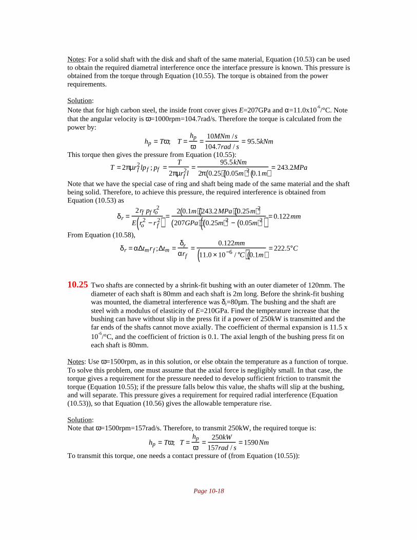
Page 10-18
Notes: For a solid shaft with the disk and shaft of the same material, Equation (10.53) can be usedto obtain the required diametral interference once the interface pressure is known. This pressure isobtained from the torque through Equation (10.55). The torque is obtained from the powerrequirements.
Solution:Note that for high carbon steel, the inside front cover gives E=207GPa and α=11.0x10
-6/°C. Note
that the angular velocity is ω=1000rpm=104.7rad/s. Therefore the torque is calculated from thepower by:
hp = Tω; T =hp
ω=
10MNm /s
104.7rad / s= 95.5kNm
This torque then gives the pressure from Equation (10.55):
T = 2πµr f2 lp f ; pf =
T
2πµrf2l
=95.5kNm
2π 0.25( ) 0.05m( )2 0.1m( )= 243.2MPa
Note that we have the special case of ring and shaft being made of the same material and the shaftbeing solid. Therefore, to achieve this pressure, the required interference is obtained fromEquation (10.53) as
δr =2rf pf ro
2
E ro2 − r f
2( ) =2 0.1m( ) 243.2MPa( ) 0.25m( )2
207GPa( ) 0.25m( )2 − 0.05m( )2( ) = 0.122mm
From Equation (10.58),
δr = α∆tmr f ;∆tm =δr
αrf=
0.122mm
11.0 × 10⁻⁶ / °C( ) 0.1m( )= 222.5°C
10.25 Two shafts are connected by a shrink-fit bushing with an outer diameter of 120mm. Thediameter of each shaft is 80mm and each shaft is 2m long. Before the shrink-fit bushingwas mounted, the diametral interference was δr=80µm. The bushing and the shaft aresteel with a modulus of elasticity of E=210GPa. Find the temperature increase that thebushing can have without slip in the press fit if a power of 250kW is transmitted and thefar ends of the shafts cannot move axially. The coefficient of thermal expansion is 11.5 x10
-6/°C, and the coefficient of friction is 0.1. The axial length of the bushing press fit on
each shaft is 80mm.
Notes: Use ω=1500rpm, as in this solution, or else obtain the temperature as a function of torque.To solve this problem, one must assume that the axial force is negligibly small. In that case, thetorque gives a requirement for the pressure needed to develop sufficient friction to transmit thetorque (Equation 10.55); if the pressure falls below this value, the shafts will slip at the bushing,and will separate. This pressure gives a requirement for required radial interference (Equation(10.53)), so that Equation (10.56) gives the allowable temperature rise.
Solution:Note that ω=1500rpm=157rad/s. Therefore, to transmit 250kW, the required torque is:
hp = Tω; T =hp
ω=
250kW
157rad / s= 1590Nm
To transmit this torque, one needs a contact pressure of (from Equation (10.55)):

Page 10-19
T = 2πµr f2 lp f ; p f =
T
2πµr f2 l
=1590Nm
2π 0.1( ) 0.04m( )2 0.08m( )= 19.77MPa
Therefore, the required radial interference to generate this pressure is, from Equation (10.53),
δr =2rf pf ro
2
E ro2 − r f
2( ) =2 0.06m( ) 19.77MPa( ) 0.06m( )2
210GPa( ) 0.06m( )2 − 0.04m( )2( ) = 20.3µm
The temperature rise in the ring to allow assembly is, from Equation (10.56),
∆tm =δr
αrf=
40µm
11.5 ×10⁻⁶ / °C( ) 0.04m( )= 86.9°
The temperature rise when the interference is 20.3µm is:
∆tm =δr
αrf=
20.3µm
11.5 ×10⁻⁶ / °C( ) 0.04m( )= 44.1°
Therefore, the rings can heat 86.9°C-44.1°C=42.8°C before slipping.
10.26 A 10-mm thick, 100-mm wide ring is shrunk onto a 100-mm diameter shaft. Thediametral interference is 75µm. Find the surface pressure in the shrink fit and themaximum torque that can be transmitted if the coefficient of friction µ=0.10. Themodulus of elasticity is E=210GPa.
Notes: Assuming both materials are the same, the surface pressure is obtained from Equation(10.53), and the torque from Equation (10.55). Note that the diametral interference, not the radialinterference, has been given in the problem.
Solution:Note that δr=75µm/2=37.5µm. The material for the ring and the shaft are the same, and the shaftis solid, so Equation (10.53) can be used. Therefore,
δr =2rf pf ro
2
E ro2 − r f
2( ) ; p f =δr E ro
2 − r f2( )
2r fro2 =
37.5µm( ) 210GPa( ) 0.06m( )2 − 0.05m( )2( )2 0.05m( ) 0.06m( )2
= 24.06MPa
The torque is then calculated from Equation (10.55):
T = 2πµr f2 lp f = 2π 0.10( ) 0.05m( )2 0.1m( ) 24.06MPa( ) = 3780Nm

Page 10-20
10.27 A railway car buffer has a spring consisting of11 outer rings and 11 inner rings where one ofeach ring type is a half-ring at the end of thespring. On one occasion a railway car with atotal mass of 10,000 kg rolls until it hits a rigidstop. The force stopping the car is equal in theouter and the inner rings. The speed of the carjust before the stop is 18 km/hr. Find thecompression of the outer and inner rings andthe stresses in the rings if the coefficient offriction µ=0.10 and the modulus of elasticityE=210GPa. The ring dimensions are shown insketch f. When a spring of this type iscompressed, the spring rate k (i.e., forcedivided by deformation) is
k = Pδ
=πE tan α tan α + γ( )
nry
Ay+ ri
Ai
where
α=cone angle for springγ=friction angletanγ=µ=coefficient of frictionry, ri=radii to surface center of gravityAy, Ai = cross sectional areas of rings.
Notes: This problem can be solved through equlibrium and conservation of energy.
Solution:Note that the following can be readily calculated:
γ=tan-1µ=tan
-1(0.1)=5.7°
Ay = Ai = 80( ) 30( ) + 80( ) 40( ) tan15°2
= 2829mm2
From static equilibrium, ri and ry can be calculated as:
150 − ry( )Ay = 15 2400( ) + 30 + 40tan15°3
429; ry = 132.2mm
ri − 90( )Ai = 15 2400( )+ 30 + 40tan15°3
429 ; ri = 107.8mm
Therefore, the spring constant is
k =πE tan α tan α +γ( )
nryAy
+ riAi
= π 210GPa( ) tan15° tan 15°+ 5.7°( )11+11−1( ) 103( ) 132.2
2829+ 107.8
2829
= 37.49MN / m
The kinetic energy which is in the railway car is
Uv = 12
mav2 = 12
10,000 kg( ) 18 1000( )3600
2
= 125kNm
Noting that δ=P/k, the energy needed to compress the spring is

Page 10-21
U f = Pδ2
= P2
2kThe railway car has two buffers, so conservation of energy requires:
2U f = Uv ; P2
2k= Uv ; P = 2kUv = 2 37.49MN / m( ) 125kNm( ) = 2.165MN
Therefore, the deflection of the spring is
δ = Pk
= 2.165MN37.49MN / m
= 57.7mm
σy and σi are found from:
P = πσ y Ay tan α +γ( );σy = PπAy tan α + γ( ) = 2.165MN
π 2829mm2( ) 0.37787( )= 645MPa
σi=-σy=-645MPa
10.28 A railway car weighing 20 tons has in each end two buffers of the type described inProblem 10.27. The data are Ay=Ai=200mm2, ry=70mm, ri=60mm, n=22, α=14°, γ=7°,and E=206GPa. The car hits a rigid stop with a velocity of 1 m/s. Find the maximumforce in each buffer and the energy absorbed. At what speed does the car bounce back?
PP1
=tan α +γ( )tan α −γ( )
Notes: The equations in Problem 10.27 are needed to solve this problem, as are conservation ofenergy and the definition of spring constant.
Solution:The spring constant for compression is obtained from the expression in Problem 10.27 as:
kc =πE tanα tan α + γ( )
nry
Ay+ ri
Ai
= π 206GPa( ) tan14° tan 14° +7°( )22( ) 0.070
200 ×10−6 + 0.060
200 ×10−6
= 4.32MN / m
The spring constant during release is:
kr = kctan α +γ( )tan α −γ( ) = 4.32MN / m( ) tan7°
tan21°=1.38MN / m
As in Problem 10.27, there are two buffers, so one-half the kinetic energy is absorbed in eachspring. Therefore,
12
mav2
2
=
Pmaxδmax
2= kcδmax
2
2;δmax = v
ma
2kc= 1( ) 10,000
4.32 ×106 = 0.0481m
Therefore, the maximum spring force isPmax=kcδmax=(4.32MN/m)(0.0481m)=208kN
The absorbed energy is
Ua =Pmax − Pmax
′( )δmax
2=
2.08( ) 105( ) 1− 0.32( ) 0.0481( )2
= 3400Nm
The return speed of the car after bouncing is
mavx2
2= Pmax
′δmax
22( );vx = Pmax
′δmax
ma / 2=
0.32( ) 2.08( ) 105( ) 0.0481( )10,000
= 0.565m / s

Page 10-22

Page 11-1
Chapter 11 • Shafting
11.1 A shaft assembly shown in sketch a is driven by a flat belt at location A and drives a flatbelt at location B. The drive belt pulley diameter is 300mm; the driven belt pulley is 500mm. The belts are long relative to the sheave diameter. The distance between sheaves is800 mm, and the distance from each sheave to the nearest bearing is 200 mm. The beltsare horizontal and load the shaft in opposite directions. Determine the size of the shaftand the types of steel that should be used. Assume a safety factor of 5.
Notes: This is an open-ended problem in that the shaft diameter will depend on the materialchosen. For this solution, AISI 1080 steel is used. The axes referenced in the solution have beenadded in green on the figure, as have the labels "1" and "2" for the bearings. These labels are allarbitrary. Also, the reactions at the bearings have been added in red.
Approach: This problem will require determination of the stresses in the critical section of theshaft. The first step, as always, is to find the bearing reactions. One must then calculate thenormal stress due to bending, the shear stress due to torsion and obtain the principal stresses, allas a function of shaft diameter. From this, one uses a static failure criterion (this solution uses thedistortion energy criterion) to find the minimum shaft diameter.
I. Determination of ReactionsFrom equilibrium of forces and moments in the xy plane, it can be easily shown that R1y=R2y=0.Taking equilibrium in the z-direction:
ΣFz=0=R1z-700N-200N+300N+600N+R2z
ΣM1=0=-(200N+700N)(0.2m)+(300N+600N)(1.m)+R2z(1.2m); R2z=-600NThe negative sign indicates it acts in the negative z-direction. Substituting this value into the forceequilibrium equation gives R1z=600N.
II. Identification of Critical SectionThe pulley diameters are given as 300 and 500 mm, so the radii are 150 and 250 mm. The
torque applied at point A is (700N-200N)(0.15m) = 75Nm. The torque at B is (300-600)(0.25m)=-75Nm. Therefore, the shaft sees a torque between the pulleys, but there is no torque in the shaftelsewhere. The shear force, bending moment and torque diagrams are shown. From the diagrams,it can be seen that the critical location is just to the inside of either pulley, so we take M=120Nmand T=75Nm. Note that we are neglecting shear; the shear stresses from vertical shear are a

Page 11-2
maximum at the center of the shaft and zero where thebending stresses are maximum. Shafts are considered tobe slender and more likely to fail from areas ofmaximum normal stress due to bending than from shear.This can be verified for this case by the student byrepeating the following analysis at the center of the shaftcross section.
III. Determination of Stress Components andPrincipal Stresses
Remember that since the shaft cross section iscircular, from Table 4.1 on page 148,
I =πd4
64, J =
πd4
32, c =
d
2
Therefore, from Equations (4.48) and (4.34), respectively:
σx =Mc
I=
120Nm( ) d / 2( )πd4 / 6 4( ) =
3840
πd3 Nm
τ =cT
J=
d / 2( ) 75Nm( )πd4 / 3 2( ) =
1200
πd3 Nm
Note that σy and σz are zero, so that from Equation (2.16), the principal normal stresses can befound as:
σ1,σ2 =σx + σ y
2± τxy
2 +σ x − σy( )2
4=
1
πd 3 Nm3840
2+ 12002 +
38402
4
so that
σ1 =4184Nm
πd3 , σ2 = −344
πd3 Nm
IV. Application of Failure CriterionAs discussed in the note above, this is an open ended problem, and this solution will
consider the special case of AISI 1080 steel as the shaft material. From the inside front cover, theyield strength of AISI 1080 is 380MPa. From Equations (6.10) and (6.11) on page 238, failureoccurs when
σe = σ12 + σ2
2 − σ1σ2( )1 / 2>
Sy
ns
1
πd3 Nm 41842 + −344( )2 − 4184( ) −344( )( )1 / 2>
380 × 106 N / m2
5This can be solved for d as d<0.02635m or d<26.35mm. Since shaft diameters are generallyexpressed in integers of millimeters for small shafts, it is good design practice to specify a shaftdiameter of 30 mm.
11.2 The gears in the shaft assembly shown in Fig. 11.1(a) transmit 100 kW of power androtate at 3600 rpm. Gear wheel 1 is loaded against another gear such that the force P1 acts

Page 11-3
in a 45° upward direction at a radius of 80 mm from the shaft center. The force P2 actsvertically downward at a radius of 110mm from the shaft center. The distance frombearing A to gear 1 is 100 mm, that from gear 1 to gear 2 is 85mm, and that from gear 2to bearing B is 50 mm. Do the following:
a) Draw a free-body diagram with forces acting on the shaft when bearings A and Btransmit only radial forces.
b) Give values of force components as well as the resultant force at locations A and B.c) Give the transmitted torque.d) Draw a bending moment diagram in the x-y and x-z planes along with a torque
diagram. Also, indicate what the maximum bending moment and the maximum torqueshould be.
e) Find the safety factor according to the distortion-energy-theory (DET) and themaximum shear stress theory (MSST) if the shaft has a diameter of 35 mm and ismade of high-carbon steel (AISI 1080).
Notes: As usual, we will assume that the power loss in the bearings is negligible.
Solution: The solution follows the order of the assigned questions.
I. Free Body Diagram
The sketch for the problem, with the coordinate system used in the solution as well as the forcereactions are shown above left. Above right are the xy and xz plane views of the free bodydiagram when the forces P1 and P2 act radially, that is, without the associated torques.
II. Determination of ReactionsBefore we can determine the reactions, we have to obtain P1and P2. Since the speed is
3600rpm, ω=(3600)(2π)/60=377rad/s. Therefore, from Equation (4.41),
T =hp
ω=
100,000 Nm / s
377/ s= 265Nm
We will assume that there are no torque losses in the bearings or in the gear teeth. Therefore, thetransmitted torque is applied equally and oppositely to both gears. The forces P1 and P2 can becalculated as
P1 =T
r1=
265Nm
0.08m= 3315N
P2 =T
r2=
265Nm
0.110m= 2410N

Page 11-4
We can then derive the reactions from force and moment equilibrium as follows. First, in the xyplane, using counterclockwise moments as positive, the moment and force equations yield:
MA = 0 = P1 cos45°( ) 0.1m( )∑ − P2 0.185m( ) + By 0.235m( ) ;By = 900N
Fy = 0 = Ay + P1 c o s 4 5° −P2 + By = Ay + 2344N −∑ 2410N + 900N ; Ay = −834NThen in the xz plane,
MA = 0 = P1 sin45°( ) 0.1m( ) − Bz 0.235m( );Bz = 998N∑Fz = 0 = Az − P1 s i n 4 5°+ Bz = Az − 2344N + 998N ;Az =1350N∑
The shear, bending and torque diagrams are as follows:
The resultant forces at A and B are the vector sums of their components, or
A = Az2 + Ay
2 = 1350N( )2 + −834N( )2 = 1590N
B = Bz2 + By
2 = 998N( )2 + 900N( )2 =1340N
The maximum moment occurs at either gear 1 or gear 2; in reviewing the moment diagrams, thelarger components are at gear 1, so we calculate the maximum moment as:
Mmax = 83.4Nm( )2 + 135Nm( )2 = 159Nm
III. Safety Factor of ShaftFor AISI 1080 steel, the yield strength is found on the inside front cover as 380MPa. For
the distortion-energy theory, equation (11.14) gives the safety factor for a shaft diameter ofd=35mm=0.035m as:
ns =πd3Sy
32 M2 + 3
4T 2
=π 0.035m( )3 380MPa( )
32 159Nm( )2 + 3
4265Nm( )2
= 5.73
For the maximum shear stress theory, equation (11.18) gives:
ns =πd3Sy
32 M2 + T 2=
π 0.035m( )3 380MPa( )32 159Nm( )2 + 265Nm( )2
= 5.18

Page 11-5
11.3 The shaft assembly given in Problem 11.2 has an extra loading from thermal expansionof the shaft. The bearings are assumed to be rigid in the axial direction, so that when theshaft heats up it cannot elongate but instead compressive stress builds up. Determine thethermal stresses and find the safety factor by the DET if the shaft heats up
a) 5°Cb) 15°C
Notes: There are a number of approaches for solving this problem. One could calculate thecomponent of thermal stress, bending stress and torsion shear stress and use a Mohr's circleapproach to determine the principal stresses for direct substitution in the distortion-energy theory.A simpler approach is to take advantage of the derivation in the book and use Equation (11.22).
Solution: The linear thermal expansion coefficient for steel is found from Table 3.5 on page 118as 11x10-6/°C. The stiffness of steel is found on the inside front cover as 207GPa. Taking thetemperature rise of 5°, the axial thermal stress is given by
σ = εE = αE∆T = 11 × 10−6 / °C( ) 207GPa( ) 5°C( ) = 11.4MPa
The axial load is
P = σA =σπd 2
4=
11.4MPa( )π 0.035m( )2
4= 11.0kN
Equation (11.22) can be solved for the safety factor as:
ns =πd3Sy
4 8M + Pd( )2 + 48T2=
π 0.035m( )3 380MPa( )4 8 1 5 9Nm( ) + 11.0kN( ) 0.035m( )( )2 + 48 265Nm( )2
= 5.17
If the temperature rise is 15°C, then the same approach is followed, so that P=32.9kN andns=4.24.
11.4 Given the shaft assembly in Problem 11.2, but calculating as if the AISI steel were brittle[using the maximum-normal-stress theory (MNST)], find the safety factor ns for fatigueby using the information in problem 11.2.
Notes: The solution shown here incorporates correction factors for surface finish and size onfatigue strength. Most shafts are machined or drawn; it is rare that a shaft is polished or ground,so this is the basis for the surface finish correction factor.
Solution: First, the fatigue strength of AISI 1080 steel is determined. Then, Equation (11.40)gives the solution.
I. Fatigue Properties of ShaftFrom Equation (7.7), we know that the endurance limit for steel (unmodified) is 0.5Sut,
where Sut for 1080 steel is 615MPa as found on the inside front cover. The only correction factorsthat we know must be included are the surface finish factor and the size factor. If the shaft ismachined or cold drawn then the surface finish factor is given by Equation (7.21) usingcoefficients from Table 7.3 on page 274:
k f = eSutf = 4.51( ) 615MPa( )−0.265 = 0.82
The size factor is given by Equation (7.22) on page 275 as
ks = 1.189d−0.112 =1.189 35( )−0.112 = 0.80The modified endurance limit is given by Equation (7.16) as:

Page 11-6
Se = k f ks ′ S e = k f ks 0.5Sut( ) = 0.82( ) 0.80( ) 0.5( ) 615MPa( ) = 202MPa
II. Fatigue Analysis of Shaft.The safety factor is given by Equation (11.40), where the following values are taken fromProblem 11.2:
Mm=0, Ma=159Nm, Ta=0, Tm=265Nm, d=0.035mAlso, we will assume there are no stress concentration associated with the shaft. Therefore thesafety factor is
ns = πd3Su / 1 6
Kc Mm + Su
SeMa
+ Kc
2 Mm + Su
SeMa
2
+ Kcs2 Tm + Su
SeTa
2
= π 0.035m( )3 615MPa( ) /16
615
202159Nm + 615
202159Nm
2+ 265Nm( )2
= 5.0
11.5 A bridge used for sightseeing is built in the form of a T, where the bottom of the T isfastened into the rock face. The top of the T is situated 7m horizontally from thefastening point, and the length of the cross bar is 8m, half on each side of the fasteningpoint. The bridge was built to carry 40 persons with an average weight of 75kg perperson. Assume that the weight is evenly distributed along the cross bar with a safetyfactor of 8. How large will the safety factor be if all the people gather on one end of thecross bar? The load-carrying structure in the bridge is a circular tube with outer diameterdo and inner diameter di. Use the DET and neglect the weight of the bridge.
Notes: This problem is challenging because no more data has been given than is necessary tosolve the problem. By keeping the diameters of the tube in the derivation, they eventually cancel,allowing determination of the safety factor. The instructor may wish to alter this problem byspecifying a material and a wall thickness and asking the students to determine the member'souter diameter.
Solution: The approach is to calculate the stress state for the first case and use the known safetyfactor to define a relationship between the diameters which remain. The second case is thenanalyzed, compared to the first to eliminate the known function, and the safety factor isdetermined.
I. Uniformly Distributed LoadIn this case, there is no torque, only bending, where the moment is given by:
M = 40( ) 75kg( ) 9.81m / s2( ) 7m( ) = 206,000 Nm
For the tube
c =d0
2; I =
π64
do4 − di
4( )so that the bending stress is
Page 11-7
σx =Mc
I=
206,000 Nm( ) do
2π64
do4 − di
4( )= 2.1MNm
d0
do4 − d i
4
In this case, this is the only stress and we know we achieve a safety factor of 8. Therefore weknow:
ns =Sy
σ x= 8 =
Sy
2.1MNmd0
do4 − di
4
;Sy do
4 − di4( )
do= 16.8MNm
II. Concentrated LoadIf the people are concentrated at one end of the bridge, there is, in addition to the moment, atorque given by
T=(40)(75kg)(9.81kgm/s2)(8m)/2=118kNmThe shear stress which results at the outer diameter is
τxy =Tc
J=
118kNm( ) do / 2( )π32
do4 − d i
4( )
= 0.60MNmdo
do4 − di
4
Therefore the principal stresses are, from Equation (2.16),
σ1,σ2 =σx + σ y
2± τxy
2 +σx − σy
2
2
=do 106 Nm( )
do4 − di
42.1+ 0
2± 0.602 +
2.1− 0
2
2
So that
σ1 =do 106 Nm( )
do4 − di
4 2.26( ), σ2 = −do 106 Nm( )
do4 − di
4 0.159( )
Using Equation (11.11) on page 429 gives
σ12 + σ 2
2 − σ1σ2( )1 / 2=
Sy
ns;ns =
Sy
σ12 + σ2
2 − σ1σ2( )1 / 2
=Sy 10−6 Nm( ) do
4 − di4( )
do
1
2.262 + 0.1592 + 2.26( ) 0.159( )( )1 / 2=16.8
2.38= 7.17
Alternate Solution:Use a 1 subscript for the uniformly distributed load case, and a 2 subscript for the concentratedload. As determined above, M1=M2=206kN-m, T1=0, and T2=118kN-m. Equation (11.13) gives:
d =32ns
πSyM2 +
3
4T2
1 / 3
Comparing the two loading cases, and realizing the diameter is the same for the two cases,
32ns1
πSyM1
2 +3
4T1
2
1 / 3
=32ns2
πSyM2
2 +3
4T2
2
1 / 3
Solving for ns2 and substituting for the moments and torques gives:

Page 11-8
ns2 = ns1
M12 +
3
4T1
2
M22 + 3
4T2
2
= 8( )206kNm( )2 +
3
40( )2
206kNm( )2 + 3
4118kNm( )2
= 7.17
11.6 Find the change in safety factor if the load-carrying structure in the bridge in Problem11.5 is a beam with a solid rectangular section of height h and width b instead of thehollow cylinder. Assume that h/b=6 and that the shear stress is
τmax =T b / 2( )
J* =T b / 2( )
0.298hb3 =T
0.596hb2
Notes: This is similar to problem 11.5, and follows a similar path of solution.
Solution:
I. Uniform Loading The loading hasn't changed from Problem 11.5, so the bending moment for this case is stillM=206kNm. The stress calculation is modified by using the proper formulae for a rectangularcross section:
c =h
2, I =
bh3
12so that the bending stress is
σx =206kNm h / 2( )
bh3 /12=
34kNm
b3
where we have used the relationship h/b=6 or h=6b to eliminate h.
II. Concentrated LoadingThe torque is, as in Problem 11.5, T=118kNm. The shear stress must be calculated for arectangular cross section, so using the equation for shear stress given in the problem statement,
τmax =T
0.596hb2 =118kNm
0.596 6b( )b2 =33.0kNm
b3
The stresses σx and τmax are in different locations, the tensile stress at the top of the beam and theshear stress at the mid-height of the beam. The safety factor for the tensile stress is given byσ1=σx and σ2=0. Thus the DET gives ns=Sy/σx=8. At the mid-height of the beam, the shear stressis
σ1,σ2 = ± τxy2
Thus using the distortion energy theory gives
σ12 + σ 2
2 − σ1σ2( )1 / 2= τxy
2 + τxy2 + τxy
2( )1 / 2= 3τxy
Therefore, the safety factor is given by
ns =Sy
3τxy= 4.82

Page 11-9
11.7 A ladder to a pleasure boat has two vertical aluminum sides to carry the load from thesteps bolted to them. By mistake the bolts on one side of the step were changed to blacksteel and therefore corroded away. Calculate how much the safety factor decreases ifpeople walk at the middle of the steps and all steps except the bad one are fixed to bothvertical sides. The vertical sides are much less elastic than the steps. Use MSST. Thelength of a step (width of the ladder) is 0.600m, and its cross section is 15mm thick and150mm wide.
Notes: This problem is open-ended and has many subtle aspects which would allow differentapproaches and assumptions in its solution. For example, ladders used on pleasure craft are oftenvery close to walls, so that a person will naturally place their weight on the step away from thewall end (applying a torque to the step). Also, the weight of a person has not been defined, so thedimensions of a 95th or 99th percentile person could be obtained from a human factors text. Allof these considerations are fine, but this solution merely demonstrates the general approach to thisproblem.
Solution:Moment equilibrium gives
M0-M+Tx=0; M=M0+Tx=M0-Px/2Integrating Equation (5.3) gives
dy
dx= −
M0x
EI+
Px2
2EI 2( )+ C1
The boundary conditions are, first, that at x=0, dy/dx=0, so that C1=0. The second boundarycondition is that at x=l/2, dy/dx=0, so that
0 = −M0
l
2
EI+
Pl2
4EI 4( ); M0 =
Pl
8Therefore, the moment at x=l/2 is
Mx= l / 2 =Pl
8−
Pl
4= −
Pl
8Therefore,
τ1=2τ2=P/A
σ1,σ2 =σx
2± τxy
2 +σx
2
2
If correctly mounted, this becomes:
σ1,σ2 =Plc
2 8( )I±
P
2 A
2
+Plc
16I
2
; σ1 − σ 2 = 2P
2A
2
+Plc
16I
2
If corroded, this is
σ1,σ2 =Plc
2 2( )I±
P
A
2
+Plc
16I
2
; σ1 − σ 2 = 2P
A
2
+Plc
4I
2
The safety factor decreases for the corroded bolts to
σ1 − σ2( )corroded
σ1 − σ 2( )correct
=
1
A
2+ lc
4I
2
1
2 A
2+ lc
16I
2=
1
0.15 0.15( )
2
+0.6( ) 0.0075( )
4 0.15( ) 0.015( ) 3 / 1 2( )
2
1
0.03 0.15( )
2
+ 0.6( ) 0.0075( )16 0.15( ) 0.015( ) 3 / 1 2( )
2 = 3.998

Page 11-10
11.8 Gears 3 and 4 act on the shaft shown in sketch b. The resultant gear force, PA=600lbf,acts at an angle of 20° from the y axis. The yield stress for the shaft, which is made ofcold-drawn steel, is 71,000 psi and the ultimate stress is 85,000 psi. The shaft is solid andof constant diameter. The safety factor is 2.6. Assume the DET throughout. Also, forfatigue loading conditions assume completely reversed bending with a bending momentamplitude equal to that used for static conditions. The alternating torque is zero and theGoodman relationship is assumed. Determine the safe diameter due to static and fatigueloading. Show shear and moment diagrams in the various places.
Notes: The reaction forces and their labels have been added in red to the problem sketch. It isassumed that there is no torque loss in the bearings.
Solution: The first step is to determine the force on Gear C. This is done by equating torquesapplied at the gears:
ΣT=0=PAcos20°(12in) – PCcos20°(5in); PC=1440 lbsThe torque between the gears is T=PAcos20°(12in)=6766inlb = 6.76 kipin.
I. Determination of Reactions and Shear and Moment Diagrams.Now obtain the reactions be looking at the x-y and x-z planes separately. In the xy plane:
ΣMO=0=(PAcos20°)(20in)+By(36in)-PCsin(20°)(46in); By=316 lbs
ΣFy=0=Oy+PAcos20°+By-PCsin20°; Oy=-387 lbs.
And in the x-z plane:ΣMO=0=PAsin20°(20in)-Bz(36in)-PCcos20°(46in); Bz=-1615lbs
ΣFz=0=Oz+Bz-PAsin20°+PCcos20°; Oz=467 lbs
The shear and bending moment diagrams can then be constructed for the xy and xz planes as:

Page 11-11
The moments at A and B are calculated from the Pythagorean theorem and are 12.1 kip-in at Aand 14.4 kipin at B. This means that the section of the shaft just inside the gear at B is critical, sowe take T=6.76 kipin, and M=14.4 kipin. For the shaft material, Sy=71,000 psi, Su=85,000psi.
II. Static AnalysisUsing the distortion-energy theory, Equation (11.13) gives:
d =32ns
πSyM2 +
3
4T 2
1 / 3
=32 2.6( )
π 71000psi( ) 14400inlb( )2 +3
46760 inlb( )2
= 1.8in
III. Fatigue AnalysisFor fatigue analysis, using MM=0 and MA=14.4 kip-in, TA=0 and TM=6.76 kipin, we need theendurance limit:
′ S e = 0 . 5Su = 0.5(85,000psi) =42,500 psiKf=0.58; ks=0.869(2)-0.112=0.8041, so Se=19.821 ksi
From Equation (11.38):
d = 32ns
πSyMm +
Sy
SeK f Ma
2
+ 3
4Tm +
Sy
SeKfsTa
2
1 / 3
= 32ns
πSy
Sy
SeK f Ma
2
+ 34
Tm2
= 2.18in
Rounding this to the nearest quarter inch shaft suggests using a 2.25 inch diameter.
11.9 Derive Equation (11.39) of the text. Start by showing the stresses acting on an obliqueplane at angle φ. The MNST should be used, implying that the critical stress line extendsfrom Se/ns to Su/ns.
Notes: The approach is very similar to the derivation of Equation 11.31. The derivation starts onpage 432.
Solution:For a brittle material, Figure 11.4(b) becomes the modified sketch shown to the left below.
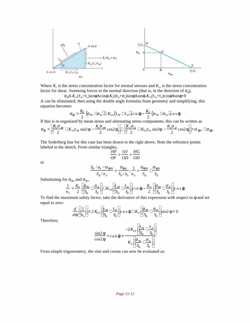
Page 11-12
Where Kc is the stress concentration factor for normal stresses and Kcs is the stress concentrationfactor for shear. Summing forces in the normal direction (that is, in the direction of σφ),
σφA-Kcs(τm+τa)sinφAcosφ-Kc(σm+σa)sinφAsinφ-Kcs(τm+τa)cosφAsinφ=0A can be eliminated; then using the double angle formulas from geometry and simplifying, thisequation becomes
σφ = Kc
2σm +σa( )+ Kcs τm + τa( )s i n 2φ − Kc
2σm + σa( )c o s 2φ
If this is re-organized by mean stress and alternating stress components, this can be written as
σφ =Kcσ m
2+ Kcsτm sin2φ −
Kcσ m
2cos2φ
+
Kcσa
2+ Kcsτa sin2φ −
Kcσ a
2cos2φ
= σ φm + σφa
The Soderberg line for this case has been drawn to the right above. Note the reference pointslabeled in the sketch. From similar triangles,
HF
OF=
OJ
OD=
HG
ODor
Su / ns −σφm
Su / ns=
σφa
Se / ns;
1ns
=σφm
Su+
σφa
SeSubstituting for σφm and σφa,
1ns
= Kc
2σm
Su+ σa
Se
+ Kcs
τ m
Su+ τa
Se
s i n 2φ − Kc
2σm
Su+ σa
Se
c o s 2φ
To find the maximum safety factor, take the derivative of this expression with respect to φ and setequal to zero:
ddφ
1ns
= 2 Kcs
τm
Su+ τa
Se
c o s 2φ + Kc
σm
Su+ σa
Se
sin2 φ = 0
Therefore,
sin2 φcos2φ
= t a n 2φ =−2Kcs
τm
Su+ τa
Se
KcσmSu
+ σaSe
From simple trigonometry, the sine and cosine can now be evaluated as:

Page 11-13
sin2 φ =2Kcs
τm
Su+ τa
Se
Kc2 σ m
Su+ σa
Se
2
+ 4Kcs2 τm
Su+ τa
Se
2
cos2φ =−Kc
σm
Su+ σa
Se
Kc2 σ m
Su+ σa
Se
2
+ 4Kcs2 τm
Su+ τa
Se
2
Substituting into the relationship for ns above gives
1ns
= Kc
2σm
Su+ σa
Se
+ Kcs
τ m
Su+ τa
Se
2Kcsτm
Su+ τa
Se
Kc2 σm
Su+ σa
Se
2
+ 4Kcs2 τm
Su+ τa
Se
2− Kc
2σm
Su+ σa
Se
−Kcσm
Su+ σa
Se
Kc2 σ m
Su+ σa
Se
2
+ 4Kcs2 τm
Su+ τa
Se
2
1
ns=
Kc
2
σm
Su+
σa
Se
+
Kc2 σ m
Su+
σa
Se
2
+ 4Kcsτ m
Su+
τa
Se
2
2 Kc2 σ m
Su+
σa
Se
2
+ 4Kcs2 τm
Su+
τa
Se
2
or, rearranging
2Su
ns= Kc σm +
Suσ a
Se
+ Kc
2 σ m +Su
Seσa
2
+ 4Kcs2 τm +
Su
Seτa
2
which is the desired relationship.
11.10 The shaft shown in sketch c rotates at 1000 rpm and transfers 6kW of power from inputgear A to output gears B and C. The spur gears A and C have pressure angles of 20°. Thehelical gear has a pressure angle of 20° and a helix angle of 30° and transfers 70% of theinput power. All important surfaces are ground. All dimensions are in millimeters. Theshaft is made of annealed carbon steel with Sut=636 MPa and Sy=365 MPa.a) Draw a free body diagram as well as the shear and moment diagrams of the shaft.b) Which bearing should support the thrust load?c) Determine the minimum shaft diameter for a safety factor of 2 and 99% reliability.
Notes: The drawing only shows the shaft; the bearings would be mounted on the shouldersmachined into the shaft. We will merely refer to the bearings as D and E according to the sketchabove. Also, the sketch has the reactions added in red and the applied force components as

Page 11-14
indicated, which will then serve as a free body diagram. Note that gear C's matching gear has notbeen drawn; this solution places it as shown. Also, the problem statement doesn't indicate adirection of rotation for the shaft; the direction of the forces acting tangent to the shaft can beopposite of what is in this solution, but this does not affect the end result nor approach to theproblem. Finally, we are not told how the shaft loads vary or even if they do vary. This can leadto some differences in approaches for solving the problem; in this solution we will note that byspecifying surface finish, fatigue must be a consideration, so we treat the loads as mean loads,take the load variation to be zero and use the fatigue equations for shaft design.
Solution:I. Determination of Reactions, Shear and Moment Diagrams
First of all, let us note that the angular velocity of the shaft is 1000rpm=104.7rad/s. Sincethere is 6 kilowatts transmitted from the drive gear A, then the torque applied at this location isobtained from:
hp=Tω;6000Nm/s=TA(104.7rad/s);TA=57.3NmSince gear B transmits 70% of the power, and the shaft speed is constant, then the torquetransmitted at B is (0.7)(57.3)=40.1Nm, and the torque at gear C is 17.2Nm. The forces can thenbe calculated. For gear A, since 57.3Nm is transmitted and the diameter of the gear is 700mm, thetangential force is
Az=TA/rA=(57.3Nm)/(0.35m)=163.7NSince the pressure angle is 20°, then
tan20°=Ay/Az;Ay=Aztan20°=(163.7N)tan20°=59.6NSimilarly,
Bz=TB/rB=(40.1Nm)/(0.2m)=200N, By=Bztan20°=73N, Bx=Bztan30°=116N,Cz=TC/rC=(17.2Nm)/(0.09m)=191N, Cy=Cztan20°=69.56N.
Dx will be equal and opposite to Bx (see the discussion below regarding why the thrust force istaken at D). Dy and Ey are obtained by moment and force equilibrium in the xy plane:
ΣMD=0=-Cy(90mm)+By(270mm)+Ay(380mm)-Ey(460mm); Ey=78.5N
ΣFy=0=Dy+Cy-By-Ay+Ey=Dy+69.56N-73N-59.6N+78.5N; Dy=-15.5NFrom equilibrium in the xz plane:
ΣMD=0=Cz(90mm)-Bz(270mm)+Az(380mm)+Ez(460mm);Ez=-55N
ΣFz=0=Dz+Cz-Bz+Az+Ez=Dz+191N-200N+163.7N-55N;Dz=-100NThe desired shear, axial force, moment and torque diagrams are as follows.

Page 11-15
II. Thrust LoadThe axial force arises because of the use of a helical gear at B. Thrust loads are not
unusual and will be discussed in much greater detail in Chapter 13. In this case, notice that theaxial force acts to the left according to the drawing of the helical gear. If the thrust load is takenby the bearing on the right, this may excessively load the bearing mounting. If the thrust load istaken by the bearing on the right, then the load is transferred through the shaft shoulder that hasbeen machined to facilitate this transfer. For this reason, the left bearing should take the thrustload.
III. Selection of Shaft Diameter.From the shear and bending moment diagrams, it is clear that the critical location for the
shaft is at point B. We will ignore the contribution of the axial force P, since the stress itcontributes is going to be very small (on the order of one megapascal for a diamter of 10millimeters - clearly negligible). The loading at this location is Tm=57.3Nm, Ta=Mm=0 and thebending moment amplitude is
MB = 7.59Nm( )2 + 8.36Nm( )2 = 11.3NmWe will use Equation (11.35) on page 435 to get the shaft diameter, but we first need themodified endurance limit for the shaft. Equation (11.35) gives the diameter but note that we needto determine the endurance limit for the shaft first. Using the approach described in detail inChapter 7, the endurance limit is (0.5)Sut=0.5(636MPa)=318MPa. kf is given by Eq. (7.21) as
k f = eSutf = 1.58( ) 636( )−0.085 = 0.91
ks is obtained from Equation (7.22) as ks=1.189d-0.112
, and kr is obtained from Table 7.4 as 0.82.Therefore the modified endurance limit is
Se = k f kskr ′ S e = 0.91( ) 1.189d −0.112( ) 0.82( ) 318MPa( ) = 279MPa( )d −0.112
Note that this is true for d in millimeters only (which was the requirement for application ofEquation (7.22)). Therefore, so that d is in meters we can write:
Se = kbkskr ′ S e = 0.91( ) 1.189d −0.112( ) 0.82( ) 318MPa( ) = 279MPa( ) 1000d( )−0.112
From Equation (11.35),

Page 11-16
d = 32ns
πSyMm +
Sy
SeK f Ma
2
+ Tm +Sy
SeK fsTa
2
1 / 3
= 32ns
πSy
Sy
SeMa
2
+ Tm2
1 / 3
= 32 2( )π 365MPa( )
365
279 1000d( )−0.112 11.3Nm( )
2
+ 57.3Nm( )2
1 / 3
Evaluating this numerically gives d=0.0150m. A value of 15 mm could be specified, which mayeven allow the use of standard bar stock for manufacturing the shaft, but it is common practice toround up to the next highest five millimeter diameter, so a better design practice would be tospecify a 20mm shaft diameter.
11.11 In Problem 11.10 if the shaft diameter is 30 mm and the shaft is made of AISI 1080 cold-drawn steel, what is the safety factor while assuming 90% reliability?
Notes: This problem is straightforward after Problem 11.10 has been completed.
Solution:The forces, shear and moment diagrams and loading are all the same. However, AISI 1080 has anultimate strength of 615MPa and a yield strength of 380MPa. Calculating a modified endurancelimit as in Problem 11.10, the unmodified endurance limit is (0.5)Sut=0.5(615MPa)=307.5MPa. kf
is given by Eq. (7.21) as
k f = eSutf = 1.58( ) 615( )−0.085 = 0.91
ks is obtained from Equation (7.22) as ks=1.189d-0.112
,=1.189(30)-0.112
=0.81 and kr is obtained fromTable 7.4 as 0.90. Therefore the modified endurance limit is
Se = k f kskr ′ S e = 0.91( ) 0.81( ) 0.90( ) 307.5MPa( ) = 204MPaTherefore, Equation (11.34) gives:
ns =πd3Sy
32 Mm +Sy
SeK f Ma
2
+ Tm +Sy
SeK fsTa
2=
πd3Sy
32Sy
SeMa
2
+ Tm( )2
= π 0.030m( )3 380 MPa( )
32380 × 11.3Nm
204
2+ 57.3Nm( )2
= 16.5
11.12 The rotor shown in sketch d has a stiff bearing on the left. Find the critical speed whenthe shaft is made of steel with E=210GPa.

Page 11-17
Note: This is a single mass system; the critical speed is given by Equation 11.50 as soon as theend deflection is determined. This is the most work in the problem; the approach is the same as inChapter 5, or else one can use the solution, readily available in any solid mechanics textbook, of
ymax = W6 EI
x2( ) 3l − x( )
Solution: This is a single mass system, and the critical speed is given by Equation (11.50) onpage 442 as
ω = gδ
δ is the maximum deflection of the beam, and for the system shown in the sketch, it is thedeflection caused by the 100kg mass (981N force). We need to derive the deflection of thecantilevered beam.
I. Calculation of Mass DeflectionThe moment as a function of x can be found from statics (and is left for the student to derive) as
M=W(l-x)Where W is the 981N load at the free end and l is the beam length (500mm or 0.5m). FromEquation (5.3) on page 183,
d2y
dx 2 = − MEI
= − W l − x( )EI
Integrating two successive times yields:dydx
= − WEI
lx − 12
x2
+ A
y = − WEI
12
lx2 − 16
x3
+ Ax + B
The boundary conditions for a clamped end are that the slope and the displacement are zero;therefore, A and B are zero. At x=l, which is the position of the mass and also of maximumdeflection,
y = − WEI
12
l3 − 16
l3
= − Wl3
3EIThe negative sign indicates the deflection is downwards; for determination of the critical
frequency the absolute deflection is used, so we use the value of δ=Wl3/3EI.
II. Determination of Critical FrequencyFrom Equation (11.50) and noting that W=mg and I=πd4/64,
ω = gδ
= 3gEI
Wl3= 3Eπd4
64ml3= 3 210GPa( )π 0.08m( )4
64 100kg( ) 0.5m( )3= 318rad / s
The shaft speed is then easily calculated asNa = 318rad / s( ) 60s / m i n( ) 1rev / 2πrad( ) = 3040rpm
11.13 Determine the critical speed in bending for the shaft assembly shown in sketch e. Themodulus of elasticity of the shaft is E=207GPa, its length l=350mm, its diameter d=8mm,and the rotor mass ma=2.3kg.

Page 11-18
Notes: This is a single mass system; the critical speed is given by Equation 11.50 as soon as themass deflection is determined. This is the most work in the problem. This solution will usesingularity functions to get the deflection at the location of the mass, but other approaches can bepursued.
Solution: The left bearing is referred to as A, the right as B as shown in the figure. The reactionscan be found through statics as Ay=2W/3, By=W/3.
I. Determination of Mass DeflectionThe load intensity function can be written as (neglecting the force at B, since our interest onlyextends to the location of the mass):
q(x) = − 2W3
x −1 + W x − l3
−1
From Equation (2.4) on page 41,
V(x) = − q(x)dx−∞
x
∫ = 2W3
x 0 − W x − l3
0
+ C1
M(x) = V(x)dx−∞
x
∫ = 2W3
x 1 − W x − l3
1
+ C1x + C2
where C1 and C2 are constants of integration, They can be evaluated by noting that because of thesimple supports represented by the bearings, the moment is zero at x=0 (therefore C2=0) and thatthe moment is zero at x=l (therefore C1=0). Then applying Equation (5.3),
d2y
dx 2 = − MEI
= − 2W3EI
x 1 + WEI
x − l3
1
Integrating twice yields
y = − W9EI
x 3 + W6EI
x − l3
3
+ C3x + C4
Where C3 and C4 are constants. The boundary conditions are that y=0 at x=0 (yielding C4=0) andy=0 at x=l, yielding
0 = − W9EI
l3 + W6EI
23
l3
+ C3l ;C3 = 5Wl2
81EISubstituting this into the expression for deflection and evaluating this function at x=l/3 gives:
y x = l3
= δ = − W
9EIl3
3
+ 5Wl2
81EIl3
= − Wl3
243EI+ 5Wl3
243EI= 4Wl3
243EI
Now, since W=(2.3kg)(9.81m/s2)=22.6N, l=0.35m, E=207GPa amd I=πd
4/64 with d=0.008m, δ is
calculated as 0.000383m

Page 11-19
II. Calculation of Critical FrequencyThe critical frequency is given by Equation (11.50):
ω = gδ
= 9.81m / s2
0.000383m= 160rad / s
The critical shaft speed is then 1530rpm.
11.14 Calculate the diameter of the shaft in the assembly shown in sketch f so that the firstcritical speed is 9000 rpm. The shaft is made of steel with E=207GPa. The distancea=300mm and the mass ma=100kg. The mass of the shaft is neglected. Use both theRayleigh and Dunkerley methods.
Notes: This is a multiple mass system, and the solution can be found from Equations (11.57) and(11.58). To use either of these equations, we must calculate deflections of the shaft under avariety of conditions. This is the lengthiest part of the problem.
Solution:I. Calculation of DeflectionsFirst of all, note that the loads are PA=200kg(9.81m/s2)=1960N, PB=981N, and I=πd
4/64. The
desired critical frequency is 9000rpm=942rad/s. This solution takes advantage of the deflectionequation given on page 193 combined with the principle of superposition. To differentiate effects,we will refer to deflections as "yij" where the deflection is at location i due to mass j. If we breakthe beam into two problems, where only one mass exists, we get the following:Deflections at A: Deflections at B:a) Use a=0.3m, b=0.6m, l=0.9m, P=1960N.Using x=l/3=0.3m gives the deflection under
gear A as yAA=2.31x10⁻⁹m
5/d
4.
b) Use a=0.6m, b=0.3m, l=0.9m, P=981N,
x=0.3m gives yAB=0.1013x10⁻⁹m
5/d
4. (Note that
the <x-a> term is zero)
a) use a=0.3, b=0.6, l=0.9, P=1960, x=0.6, so
that yBA=2.03x10⁻⁹m
5/d
4
b) Use a=0.6, b=0.3, l=0.9, P=981, x=0.6 so
that yBB=1.16x10⁻⁹m
5/d
4
Therefore, yA=yAA+yAB=3.33x10⁻⁹m
5/d
4 and yB=yBA+yBB=3.19x10
-9m
5/d
4.
II. Rayleigh MethodEquation (11.57) on page 442 gives the critical frequency as a function of load and deflections.For this case, Equation (11.57) becomes:

Page 11-20
ωcr = 942rad / s =g WAδA + WBδB( )
WAδ A2 + WBδB
2
=9.81m / s2( ) 1960N( ) 3.33 ×10⁻⁹m5 / d4( )+ 981N( ) 3.19 ×10⁻⁹m 5 / d4( )[ ]
1960N( ) 3.33×10⁻⁹ m5 / d 4( )2+ 981N( ) 3.19 ×10⁻⁹m5 / d 4( )2
This is solved numerically as d=0.131m=131mm.
III. Dunkerly MethodEquation (11.58) and (11.50) combine to give the estimate of critical speed as:
1
ωcr2 =
1
ω12 +
1
ω 22 =
1
g /δ1( )2 +1
g /δ2( )2 =δ1 + δ 2
g;ωcr =
g
δ1 + δ2
Substituting for δ1 and δ2 gives d=0.133m=133mm.
11.15 The simple support shaft shown in sketch g has two weights on it. Neglect the shaft
weight. Using the Rayleigh method for the stainless steel (E=26 x 106 psi) shaft,
determine the safe diameter to ensure that the first critical speed is no less than 3600rpm.
Note: The approach is the same as for Problem 11.14.
Solution:I. Calculation of DeflectionsFirst of all, note that the loads are PA=300lb, PB=500lb, and I=πd
4/64. The desired critical
frequency is 3600rpm=377rad/s. This solution takes advantage of the deflection equation givenon page 193 combined with the principle of superposition. To differentiate effects, we will referto deflections as "yij" where the deflection is at location i due to mass j. If we break the beam intotwo problems, where only one mass exists, we get the following:Deflections at A: Deflections at B:a) Use a=8in, b=12in, l=20in, P=300lb. Usingx=8in gives the deflection under gear A as
yAA=0.036in5/d
4.
b) Use a=15in, b=5in, l=20in, P=500lb, x=8in
gives yAB=0.041in5/d
4.
a) use a=8, b=12, l=20, P=300, x=15, so that
yBA=0.024in5/d
4
b) Use a=15, b=5, l=20, P=500, x=15 so that
yBB=0.0367in5/d
4
Therefore, yA=yAA+yAB=0.077in5/d
4 and yB=yBA+yBB=0.0607in
5/d
4.
II. Rayleigh Method

Page 11-21
Equation (11.57) on page 442 gives the critical frequency as a function of load and deflections.For this case, Equation (11.57) becomes:
ωcr = 377rad / s =g WAδA + WBδ B( )
WAδ A2 + WBδB
2
=386.4in / s2( ) 300 lb( ) 0.077in5 / d4( ) + 500lb( ) 0.0607in5 / d 4( )[ ]
300 lb( ) 0.077in5 / d4( )2+ 500 lb( ) 0.0607in5 / d4( )2
This is solved numerically as d=2.23in
III. Dunkerly MethodEquation (11.58) and (11.50) combine to give the estimate of critical speed as:
1
ωcr2 =
1
ω12 +
1
ω 22 =
1
g /δ1( )2 +1
g /δ2( )2 =δ1 + δ 2
g;ωcr =
g
δ1 + δ2
Substituting for δ1 and δ2 gives d=2.26in.
11.16 Determine the first critical speed by the Dunkerly and Rayleigh methods for the steelshaft shown in sketch h. Neglect the shaft mass. The moment of inertia is I=πr4/4, wherer is the shaft radius. The method of superposition may be used with the following given:
δ = P6 EI
bx3
l− x − a 3 −
xb l2 − b2( )l
Notes: The approach is the same as for Problem 11.14
Solution:I. Calculation of DeflectionsFirst of all, note that the loads are PA=120lb, PB=80lb, and I=πd
4/64=πr4/4in
4. To differentiate
effects of the two loads, we will refer to deflections as "yij" where the deflection is at location idue to mass j. If we break the beam into two problems, where only one mass exists, we get thefollowing:Deflections at A: Deflections at B:a) Use a=20in, b=70in, l=90in, P=120lb. Usingx=20in gives the deflection under gear A asyAA=0.0367in
b) Use a=60in, b=30in, l=90in, P=80lb, x=20ingives yAB=0.0256in
a) use a=20, b=70, l=90, P=120, x=60, so thatyBA=0.0385in
b) Use a=60, b=30, l=90, P=80, x=60 so thatyBB=0.0407in
Therefore, yA=yAA+yAB=0.0626in and yB=yBA+yBB=0.0792in

Page 11-22
II. Rayleigh MethodEquation (11.57) on page 442 gives the critical frequency as a function of load and deflections.For this case, Equation (11.57) becomes:
ωcr =g WAδA + WBδ B( )
WAδ A2 + WBδ B
2 =386.4in / s2( ) 120 lb( ) 0.0626in( )+ 80lb( ) 0.0792in( )[ ]
120lb( ) 0.0626in( )2 + 500lb( ) 0.0792in( )2
This is solved as ωcr=74.2rad/s=708rpm.
III. Dunkerly MethodEquation (11.58) and (11.50) combine to give the estimate of critical speed as:
1
ωcr2 =
1
ω12 +
1
ω 22 =
1
g /δ1( )2 +1
g /δ2( )2 =δ1 + δ 2
g;ωcr =
g
δ1 + δ2
Substituting for δ1 and δ2 gives ωcr=70.52rad/s=673rpm.
11.17 Calculate the diameter d of the shaft in sketch f so that the lowest critical speed becomes9000rpm. The modulus of elasticity E=107GPa, the distance a=300mm, and the massma=100kg. Neglect the mass of the shaft. Use the Rayleigh and Dunkerly methods.
Notes: The approach is the same as for Problem 11.14
Solution:I. Calculation of DeflectionsThe only change from Problem 11.14 is that the stiffness has changed from 207GPa to 107 GPa.Since the deflections are linearly related to the stiffness, we can directly write the deflectionsfrom the data in problem 11.14 as:
yA=(3.33x10⁻⁹m
5/d
4)(207/107)=6.44x10
-9m
5/d
4
yB=(3.19x10⁻⁹m
5/d
4)(207/107)=6.17x10
-9m
5/d
4
(The alternative is to repeat the approach in problem 11.14)
II. Rayleigh MethodEquation (11.57) on page 442 gives the critical frequency as a function of load and deflections.For this case, Equation (11.57) becomes:
ωcr = 942rad / s =g WAδA + WBδ B( )
WAδ A2 + WBδB
2
=9.81m / s2( ) 1960N( ) 6.44 ×10⁻⁹m5 / d4( ) + 981N( ) 6.17 ×10⁻⁹m5 / d4( )[ ]
1960N( ) 6.44 ×10⁻⁹ m5 / d 4( )2+ 981N( ) 6.17 × 10⁻⁹ m5 / d4( )2
This is solved numerically as d=0.155m=155mm.
III. Dunkerly MethodEquation (11.58) and (11.50) combine to give the estimate of critical speed as:
1
ωcr2 =
1
ω12 +
1
ω 22 =
1
g /δ1( )2 +1
g /δ2( )2 =δ1 + δ 2
g;ωcr =
g
δ1 + δ2
Substituting for δ1 and δ2 gives d=0.156m=156mm.

Page 11-23
11.18 The rotor in sketch i has a shaft diameter of 32 mm, and the disk mass is 170kg. Calculatethe critical speed if the spring rates are 1668 and 3335 N/m, and are the same in alldirections. The elastic modulus E=206GPa. For a shaft without springs, the influence
coefficient α11=l3/6EI.
Solution:The centrifugal force is
P=mayωcr2
The deformation is y=αP, so ωcr2=1/(maα)
The deformation comes from the springs and shaft in bending
α = 14C1
+ 14C2
+ l3 64( )6 Eπd4
Therefore,
ωcr2 =
1
170kg( ) 0.16m( )3 64( )6 206GPa( )π 0.032m( )4 +
1
4 1.668MN / m( )+
1
4 3.335MN / m( )
= 2 0 , 3 3 8 /s2
or ωcr=143rad/s=1360rpm.
11.19 Calculate the critical speed for a rotor shown in sketch j that has two moment-freebearings. The shaft has a diameter of 20mm and is made of steel with E=206GPa.
Notes: The difficult part of this problem is obtaining the deflection at the mass. This can be doneusing the approach in Chapter 4, or else a solution can be obtained from a solid mechanics text orstress analysis handbook. The deflection at the mass is given by
δ = 2Pl3
3EIand this will be used in the solution below.
Solution: From Equation (11.50), the critical speed is given by
ω = gδ
= g 3EI( )2 Pl3
= 3EI
2mal3=
3 206GPa( ) π64
0.020m( )4
2 7kg( ) 0.2m( )3= 208rad / s
Page 11-24
where the equation for deflection given above has been used, as has been the substitution P=mag.The critical speed of 208 rad/s can also be expressed as 1990rpm.
11.20 A flywheel has a hub made of aluminum alloy 2014. The hub is connected to the AISI1040 steel shaft with a flat, 15-mm long key made of AISI 1020 steel. Dimension the keyso that it can transmit 20Nm of torque with a safety factor of 3.
Notes: Often, the key is sized arbitrarily given the torque that must be transmitted. This problemintroduces an additional constraint, namely that a soft hub is used, so the key must not causefailure of the hub. One can foresee this occurring if a very short key is used - the bearing stresseswould cause the hub to plastically deform. We will also assume that the same safety factor is usedfor the hub and the key, which is not normally the case. Usually, the hub uses a much highersafety factor to ensure that no damage will occur in the case of excessive torque. The point of akey is to protect the expensive components, which will not occur if it fails at the same time asthese components. However, the solution scheme for a different safety factor is straightforwardafter doing this problem.
Solution: First we obtain the material properties from the inside front cover as Sy,steel=295MPa,Sy,al=97MPa.
I. Analysis of keyThe key shear criterion is given by Equations 11.60 and 11.61, which when combined give:
τ = 2Tdwl
=Ssy
ns=
0.40Sy
ns;dw = 2Tns
0.40dlSy= 2 20Nm( ) 3( )
0.40 0.015m( ) 295MPa( ) = 6.78 ×10⁻⁵m2
II. Analysis of hubThe bearing stress on the softer hub must be considered. Equations 11.63 and 11.64 give
σ = 4Tdlh
=0.90Sy
ns;dh = 4Tns
0.90lSy= 4 20Nm( ) 3( )
0.90 0.015m( ) 97MPa( ) =1.83 ×10⁻⁴m2
This gives the dimensions of the key as a function of shaft diameter. If the diameter of the shaft is20 mm, then the key dimensions are w=3.39mm and h=9.16mm
11.21 A jaw crusher is used to crush iron ore down to the particle size needed for iron ore pelletproduction. The pellets are later used in a blast furnace to make steel. If the iron orepieces coming into the crusher are too large, the crusher is protected by a torque-limitingkey made of copper. The torque on the 400-mm diameter shaft connecting the flywheelwith the jaw mechanism should never go over 700kN-m. Dimension the copper key sothat the shaft is not damaged when an oversized ore particle comes into the crusher.
Notes: This is an open ended problem, since the shear pin will ultimately require an area basedon the material’s ultimate strength. Good design practice would be to use the same length of pinas the hub on which it is attached - this minimizes the bearing stresses on the hub for a given pinheight.
Solution:Note that for shear pin failure, the ultimate strength should be used, which is 220 MPa for copper(see inside cover of text). The shear force is given by τwl=0.5Suwl (using the maximum shearstress theory). The torque developed is T=0.5Suwlr=700kN-m. The area of the key is then

Page 11-25
wl =700kN − m
0.5 220MPa( ) 0.2m( ) = 0.032m2
Any combination which gives this area will work; arbitrarily setting w=d/4=100mm gives l=320mm. Note: if the distortion energy theory is used, l=275mm.
11.22 The output torque of a flywheel for each revolution of a shaft is 10 Nm from 0 to π and120Nm from π to 2π. The coefficient of fluctuation is 0.04 at an average speed of 2000rpm. Assume that the flywheel disk is an AISI 1040 steel plate of 30-mm constantthickness. Determine the following:
a) Average load torque.b) Locations θωmax and θωmin
c) Energy requiredd) Outside diameter of flywheel
Notes: This problem is straightforward and is very similar to Example 11.7 on page 451.The plot of torque as a function of phase from 0 to 2π is:
Since the intervals are equal, Tave is easily calculated as 65Nm. If this torque is applied, the shaftwill accelerate over the 0 to π interval, and decelerate between π and 2π. Therefore, the maximumangular velocity will be at π, the minimum at 2π. The energy needed is
Ke = T − Tave( )dφπ
2π
∫ = 55πNm
The mass moment of inertia required is given by Equation (11.72):
Im =Ke
C f ωave2 =
55πNm
0.04( ) 2000 ×2π60
2
sec−2= 0.098Nmsec2 = 0.098kgm2
If the flywheel is a disk of thickness 0.030m, and recognizing for steel ρ=7850kg/m3,
Im = 0.098kgm2 =πd2tm ρ
4
d2
8
;d = 0.255m = 255mm
11.23 The output torque of a flywheel for each revolution of a shaft is 200 in-lbf from 0 to π/3,1600 in-lbf from π/3 to 2π/3 , 400in-lbf from 2π/3 to π, 900 in-lbf from π to 5π/3, and200in-lbf from 5π/3 to 2π. Input torque is assumed to be constant. The average speed is860rpm. The coefficient of fluctuation is 0.10. Find the diameter of the flywheel if it iscut from a 1-in thick steel plate.

Page 11-26
Notes: This problem is relatively straightforward. The steps on pages 450-451 can serve as auseful guide to solving this problem. A useful material constant which is needed is the density of
steel, which from the inside front cover is ρ=7840kg/m3=0.28lb/in
3.
Solution:1. Plot of load torque Tl versus θ for one cycle:The plot is given below. To aide in the determination of the average torque, the areas of eachsection have been marked in the curve.
2. Determination of average torqueThe average torque is the total area under the curve divided by the base length (2π). Therefore theaverage torque is 700inlb.3. From the plot of torque versus angular position, the critical area seems to be the sectionof high torque between π/3 and 5π/3. This could be confirmed by considering all possiblesections and taking the one which maximizes the kinetic energy change, but intuition in this caseis correct. Therefore, we will evaluate the kinetic energy change between π/3 and 5π/3.4. The kinetic energy change over this interval is
Ke = Tl − Tave( )dθ∫ = 1600 − 700( )inlbπ3
+ 400 − 700( )inlbπ3
+ 900 − 700( )inlb2π3
= 1000π3
inlb
5. The average speed is given as ωave=860rpm=90.1rad/s.6. The coefficient of fluctuation is given as 0.10. The required mass moment of inertia is,from Equation (11.72)
Im =Ke
C f ωave2 =
1000πinlb
3 0.10( ) 90.1rad / s( )2 = 0.411πinlbs2
And, from Table 4.2 on page 150 for a disk with a thickness of 1 in,
Im = 0.411πinlbs2 =mad2
8=
ρ π4
d2 t
d 2
8=
ρπd4 t
32Solving for d,
d4 =32 0.410πinlbs2( )
ρπt=
32 0.410πinlbs2( ) 386lbm
lbs2 / in
0.28lbm / in3( ) 1in( )=18128in4
or d=11.6 in. A value of 12 inches would be a good design designation.
11.24 A 20-mm thick flywheel is made of aluminum alloy 2014 and runs at 9000 rpm in aracing car motor. What is the safety factor if the aluminum is stressed to a quarter of its

Page 11-27
yield limit at 9000rpm? To decrease the flywheel outer diameter, highly dense exoticmaterials are investigated. Find the best material from Table A.2 that can be substitutedfor aluminum alloy 2014 but with the same safety factor. The flywheel is machined froma solid piece of aluminum alloy 2014 with no central hole, and the thickness cannot belarger than 20mm.
Notes: To minimize the outer diameter while maintaining the same thickness, one has to obtain adenser material. However, given a material, there is an additional requirement that maintain asafety factor of 4 at this speed. Therefore, we will calculate the stress as a function of radius forthe materials in Table A.2 in order of decreasing density until a candidate is found which gives animproved and safe design.
Solution:First of all, note that ω=9000rpm=942rad/s.I. Aluminum flywheelWe note from the text on page 452 that σθ is maximum at r=ri. With ri=r=0, Equations (11.75)and (11.76) become:
σθ = 3+ ν( )8
ρω2ro2
σr = 3+ ν( )8
ρω2ro2
Since these are principal stresses, Equation (6.10) on page 238 gives
σe = σθ2 +σ r
2 − σθσ r( )1 / 2=
3 + ν( )8
ρω2ro2
We can get the material properties for aluminum 2014 from the inside front cover as ν=0.33 and
ρ=2710kg/m3 and Sy=97MPa. Since σe=Sy/4, we can obtain ro as
ro2 =
2Sy
3 +ν( )ρω 2 = 2 97MPa( )3.33( ) 2710kg / m3( ) 942rad / s( )2 ;ro = 0.155m =155mm
or a flywheel diameter of 310mm. The mass moment of inertia is
Im = mad2
8= πd4 tmρ
32=
π 0.31m( )4 0.020m( ) 2710kg /m3( )32
= 0.049kgm2
II. Silver flywheel.Silver is a possible material in Table A.2 because of its high density. The important properties are
ρ=10490kg/m3, ν=0.37, Sy=55MPa. To get a mass moment of inertia of 0.049kgm
2, the diameter
must be
0.049kgm2 = πd 4tmρ32
;d4 =32 0.049kgm2( )
π 0.02m( ) 10490kg / m3( ) ;d = 0.221m
The stress in the silver is given by
σe = 3 + ν( )8
ρω2ro2 = 3+ 0.37( )
810490kg( ) 942rad / s( )2 0.1105m( )2 = 47.9MPa
Since this is more than one-fourth the yield strength, silver cannot be substituted for thealuminum.
III. Molybdenum flywheel

Page 11-28
Molybdenum is the next best material, with ρ=10220kg/m3, ν=0.3, Sy=565MPa. The diameter is
calculated as before as 0.223m, and the resulting stress is 41.7MPa. Since this is less than one-fourth the yield strength, molydbenum will work.
11.25 The aluminum flywheel considered in Problem 11.24 has a mass moment of inertia of
0.0025 kgm2. By mistake the motor is accelerated to 7000 rpm in neutral gear, and the
throttle sticks in the fully open position. The only way to stop the motor is to disconnectthe electric lead from the spark plug. It takes 6s before the motor is motionless.Neglecting the inertia of all movable parts in the motor except the flywheel, calculate theinternal friction moment in the motor and the (mechanical part of the) friction losses inthe motor at 5000 rpm. The friction moment is assumed to be constant at all speeds.
Notes: This problem only needs Equation (11.66) for a solution. This problem is actually anadvanced dynamics problem, where a constant torque causes a flywheel to stop from 7000rpm insix seconds.
Solution:Note that 7000rpm=733rad/s and 5000rpm=524rad/s. Equation (11.66) gives:
Tl − Tm = Imdωdt
;Tl − Tm
Imdt = dω
Here we set Tl to the frictional torque, Tm is the mean torque applied by the motor, which is zeroonce the spark plug is disengaged. Tl and Im are constants, so this equation can be integrateddirectly:
Tl
Imdt
0
6s
∫ = dω733rad /s
0
∫ ;Tl
0.0025kgm2( ) 6s( ) = −733rad / s;Tl = −0.305Nm
The negative sign indicates that it causes decelleration. The friction losses are the product oftorque and angular velocity; since the friction torque is taken as constant, this is:
hp = Tlω = 0.305Nm( ) 524rad / s( ) =160W
11.26 A one-cylinder ignition bulb motor to an old fishing boat has a flywheel that gives themotor a coefficient of fluctuation of 25% when it idles at 180 rpm. The mass moment ofinertia for the flywheel is 1.9kg-m
2. Determine the coefficient of fluctuation at 500 rpm if
the compression stroke consumes equally large energy at all speeds. Also, calculate themass moment of inertia needed to get 20% coefficient of fluctuation at 500 rpm.
Solution:First of all, at idle speed, ω=(180rpm)(2π/60)=18.8 rad/sec. If the energy is constant, fromEquation (11.71),
Ke = ImC f ωave2 = Const.; ImC f1ωave1
2 = ImC f 2ωave22
C f 2 = C f1ωave1
2
ωave22 = 0.25( ) 1802
5002
= 0.032
The kinetic energy is (1.9kgm2)(0.25)(18.8sec-1)2=169Nm. For Cf=0.2 at 500 rpm,
169Nm = Im 0.2( ) 500× 2π60
2
; Im = 0.31kgm2

Page 11-29
11.27 A flywheel for a city bus drive should store as much energy as possible for a givenflywheel weight. The diameter must be less than 1.5 m, and the mass must be smallerthan 250kg. Find which material from Tables A.1 and A.2 gives the highest possiblestored energy for a safety factor of 4 if the flywheel has constant thickness.
Notes: Equation (11.82) gives the requirement for the best performing flywheels. This equationcan be derived using an approach as in problem 11.24. However, this problem merely requiresevaluation of the performance index for the materials in Tables A.1 and A.2.
Solution:The following values are obtained for the materials in Tables A.1 and A.2:Material σmax=Sy/4, MPa ρ, kg/m
3 Mf=σmax/ρIronGray cast ironNodular cast ironMalleable cast ironAISI 1020 steelAISI 1040 steelAISI 1080 steelType 446 stainlessType 316 stainlessType 410 stainless
32.531.2568.75
5573.7587.595
86.2551.7568.75
7870715071207200786078507840750080007800
0.004130.004370.009660.007640.009380.01110.01210.0115
0.006470.00881
Aluminum (>99.5%)2014 AlCopper (99.95%)Brass (70Cu-30Zn)Bronze (92Cu-8Sn)MagnesiumMolybdenumNickelSilverTitanium
4.2524.2517.2518.75
3810.25
141.2534.513.75
60
27102800894085308800174010208900104904510
0.001570.008660.001930.002200.004320.005890.138
0.003880.001310.0133
The maximum value occurs with Molybdenum.
11.28 A flywheel on an AISI 1080 steel shaft is oscillating due to disturbances from acombustion engine. The engine is a four-stroke engine with six cylinders, so that thetorque disturbances come three times per revolution. The flywheel has a shaft diameter of
20mm and is 1 m long, and the flywheel moment of inertia is 0.5 kg-m2. Find the engine
speed at which the large torsional vibrations will appear.
Notes: This problem requires some knowledge of differential equations. The approach is to applyEquations (11.66) and (11.35) to get a differential equation in terms of angular deflection. Thesolution of this equation is sinusoidal with a characteristic frequency which yields the solution.
Solution:From Equation (11.66) and noting that dθ/dt=ω,
Tl − Tm = Imdωdt
= Imd2θdt2

Page 11-30
Where θ is the angular deflection. We take θ as zero at Tm, so that Tm is our reference and is setequal to zero. Our concern is finding what frequencies yield the extreme value of θ. Notehowever, that T is related to θ by equation (4.35) on page 155 as
T = JGθl
so combining these two equations gives a differential equation for θ as:
T = JGθl
= Imd2θdt 2 ;
d2θdt2 − GJ
Im lθ = 0
this has a solutionθ=Asinωet+Bcosωet
where
ωe =GJ
Iml=
79.62GPa( ) π32
0.02m( )4
0.5kgm2( ) 1m( )= 50.0rad / s = 478rpm
but if we take θ=0 at t=0 then B must be zero. If A is zero, there are no vibrations, which weknow is not true. Therefore, A must be non-zero and the shaft vibrates at the critical frequency of478 rpm. Note though that the engine applies torque three times per engine revolution; thereforethe critical engine rpm is one-third this answer or 160 rpm.

Page 12-1
12 • Hydrodynamic Bearings
12.1 To decrease the leakage past a seal of the type discussed in Example 12.1, the sealing gapis tapered and the film shape is
h x( ) = h0 + xdhdx
= h0 + kx
Because of the roughness of the surfaces the outlet (minimum) film thickness h0 has to be at least10µm. Find the optimum oil film shape to minimize the total leakage past the 10-mm wide sealduring a full work cycle (back and forth) of the piston when the fluid viscosity is 0.075 Pa-s, thepiston speed is 0.8 m/s in both directions, the stroke length is 85 mm, the sealing pressure is 1MPa, and the piston diameter is 50mm.
Solution:This problem can be answered directly, from a number of approaches. Note that the physicalwedge term of the Reynolds equation can generate a pressure and therefore a flow. The physicalwedge term is, from Equation (12.22),
ρ ua + ub( )2
∂h∂x
=ρ ua + ub( )
2k
the pressure leads to a Poiseuille type flow and must be minimized. This can only be done in thiscase by minimizing k, since ub is specified and the density is constant. Therefore, we set k=0,basically calling for a uniform film thickness.
To determine what that film thickness should be, note that the sealing pressure and thebearing length has been defined by the problem, as has the viscosity and the sliding speed. FromEquation (12.12), the flow per width is
qx′ = − h3
12η∂p∂x
+h ua + ub( )
2note from Figure 12.3 that either ∂p/∂x or ub will be negative, and ua is zero. Therefore, the flowis minimized by minimizing the value of h. Since we cannot have a zero gap in a seal, and in thiscase the film thickness h0 is limited to 10µm, we use this as the optimum thickness.
12.2 The oil viscosity is 0.01 Pa-s in a very wide slider bearing with an exponential oil filmshape
h=(h0+sh)e-x/l
Find the pressure distribution and calculate the load-carrying capacity per unit widthwhen the sliding speed is 10 m/s if h0=60 µm and the bearing is 0.10 m long in thedirection of motion.
Notes: This is a classic one-dimensional Reynolds equation problem. The key equation is(12.29) and the boundary conditions to be employed are that the pressure is zero at the edges ofthe bearing. This solution will demonstrate the usefulness of using non-dimensional variables, asthe solution, while possible, is much more complicated if dimensional variables are used.
Solution:

Page 12-2
I. Film ShapeThe given film shape is
h=(h0+sh)e-x/l
and is sketched to the right. Note that at x=l, h=h0,so this would yield
h0 = h0 + sh( )e−1 = h0 + sh
e;sh = eh0 − h0 = h0 e− 1( )= 60µm( ) e −1( ) =103µm
We will use non-dimensional variables, signified by capital characters, and defined as follows:
X =x
l; p =
η0ub l
sh2 P; H =
h
sh=
h0 + sh( )e−x / l
sh= H0 +1( )e− X
where H0=h0/sh=60µm/103µm=0.582. Therefore, H=1.582e-X.
II. Reynolds EquationNow that we have the film shape, the Reynolds equation in the form of Equation (12.29) can beapplied as
∂∂x
h3 ∂p∂x
= 6η0ub
∂h∂x
;∂
∂XH3 ∂P
∂X
= 6
∂H∂X
A few algebraic steps have been skipped in this derivation, but it is fairly straightforward toderive the non-dimensional Reynolds equation. In fact, the dimensionless pressure has beendefined so that many of the constants are absorbed into the pressure term in this equation.
Remember that H=1.582e-X
, so that
∂∂X
1.582e−X( )3 ∂P
∂X
= 6
∂ 1.582e −X( )∂X
; 1.5823 ∂∂X
e−3X ∂P
∂X
= −6 1.582e−X( )
∂∂X
e−3X ∂P
∂X
= − 6e−X
1.5822
Integrating twice,
P = 3e2X
1.5822 + C1e3X
3+ C2
where C1 and C2 are constants. The boundary conditions used are that the pressure is zero at theedges of the bearing. This must be the case - if there was a non-zero pressure, then oil would flowout of or into the bearing and the film thickness would increase or decrease as a result. Since weare assuming that the bearing is at steady state, we use P=0 at X=0 and P=0 at X=1 (thesecorrespond to p=0 at x=0 and p=0 at x=l, respectively). Substituting these equations:
0 = 3e0
1.5822 + C1e0
3+ C2 = 3
1.5822 + C13
+ C2
0 = 3e2
1.5822 + C1e3
3+ C2
These yield C1=-1.2039 and C2=-0.7974. Therefore the pressure is
P=1.1987e2X
-0.4013e3X
-0.7974
III. Load SupportTo obtain the load support, integrate the pressure as in Equation (12.40):

Page 12-3
Wz
wt= η0ub l2
sh2 PdX
0
1∫ = η0ub l2
sh2 1.1987e2X − 0.4013e3X − 0.7974( )dX
0
1∫
= η0ubl2
sh2
1.1987
2e2 X − 0.4013
3e3X − 0.7974X
X=0
X=1= η0ubl2
sh2 0.4789( )
Substituting for the remaining variables,
Wz
wt=
η0ubl2
sh2 0.4789( ) =
0.01Ns /m 2( ) 10m / s( ) 0.1m( )2 0.4789( )
1.031 × 10⁻⁴ m( )2 = 45kN / m
12.3 A plain journal bearing has a diameter of 2 in. and a width of 1 in. The full journalbearing is to operate at a speed of 2000 rpm and carries a load of 750lbf. If SAE 20 oil atan inlet temperature of 110°F is to be used, determine the following:a) The radial clearance for optimal load-carrying capacity, the temperature rise and
the mean temperature.b) The performance parameters: coefficient of friction, flow rate, side flow and
attitude angle.c) The kinematic viscosity of the oil at the mean temperature if the oil density is
0.89 g/cm3.
Notes: All of the information is contained in the figures in the chapter, but the approach is oftenconfusing at first because the figures must be referenced in a certain order. The student should beencouraged to keep reviewing the figures and obtaining as much information as possible;eventually sufficient information is obtained to get a solution. Also, reading figures from thetables does introduce some errors, so slight variations from the answers here should be expected.With care, answers should be within ten percent or so from those given here. The alternativeapproach, which yields a better and repeatable solution, is to numerically solve the Reynoldsequation with proper boundary conditions, a task not normally performed by designers because ofthe complexity involved.
Solution:I. Clearance and TemperaturesThe diameter-to-width ratio is λ=2, so from Figure 12.28 on page 509, Bj=0.35 and hmin/c=0.42since this is where the λ=2 curve intersects the optimum load carrying capacity curve. Using thisdata, Figure 12.30 yields rbµ/c=8, Figure 12.31 yields Q=5.2 and Figure 12.32 yields qs/q=0.75.To obtain the clearance from Equation (12.85), we need the viscosity, and to obtain the viscositywe need the mean temperature rise from Equation (12.91b). We first calculate the radial load perarea according to Equation (12.91c):
Wr* = Wr
2rbwt= 750lb
2in( ) 1in( ) = 375psi
Therefore the temperature rise (from Equation (12.91b)) is:
∆tm =0.103Wr
* rµc
Q 1 − 0.5qs
q
= 0.103 375( ) 8( )5.2( ) 1 − 0.5 0.75( )( ) = 95°F

Page 12-4
The mean temperature is tm=ti+∆tm/2=110°F+95/2°F=158°F, or around 70°C. From Figure 8.13
on page 327, η0=0.0130Ns/m2. Using the conversion factor from Table 8.2 on page 320, this is
1.88x10⁻⁶lb-s/in
2. Now, from Equation 12.85 and noting that ωb=2000rpm=209rad/s:
Bj = η0ωbrbwt
πWr
rbc
2
;c = rbη0ωbrbwt
πWrB j
1 / 2
= 1in( )1.88µlbs / in2( ) 209rad / s( ) 1in( ) 1in( )
π 750 lb( ) 0.35( )
1 / 2
= 6.9 ×10⁻⁴ in
II. Performance parametersSince rbµ/c=8, the coefficient of friction is 8c/rb=8(6.9x10-4in)/(1in)=0.0055. the flow rate isfrom the caption on Figure 12.31,
Q = 2πqrbcwtωb
;q = Qrbcwtωb
2π=
5.2( ) 1in( ) 6.9× 10⁻⁴ in( ) 1in( ) 209rad / s( )2π
= 0.120in3 / s
the side flow is obtained from qs/q=0.75, so qs is 0.75(0.120in3/s)=0.09in
3/s. The attitude angle is
obtained from Figure 12.29 as Φ=50°.
III. Kinematic ViscosityIf the oil density is 0.89g/cm
3, then the kinematic viscosity is
ηk =ηρ
=0.0130Ns / m2
890kg / m3( ) = 14.6 ×10⁻⁶m2 / s
12.4 The torque transmission in a speedometer is throughtwo circular plates, with radius r, placed in an oilbath at a distance h from each other (see sketch a).When shaft 1 suddenly starts to rotate, shaft 2 will bemoved by the shear forces in the oil. Find the angularspeed ω2 as a function of time if ω2(t=0)=0 andω1(t)=0 for t≤0. Shaft 2 has a moment of inertia J2
and the oil has viscosity η.
Notes: The approach here is to determine the torque applied by integrating the shear stress on theplates. To do this, one must use the definition of viscosity (Equation 8.11) in cylindricalcoordinates. Once the torque is obtained, the acceleration can be obtained since the moment ofinertia is given. Integrating the angular acceleration and applying the initial conditions leads tothe desired relationship.
Solution:I. Determination of TorqueWe need to determine the torque applied to the shaft. Unfortunately, most of the equations so farhave been in Cartesian coordinates, while this problem is in cylindrical coordinates. We willdetermine the total torque from
Mz = τr( )rdrdθ =∫∫ τθr0
R
∫ 2πr( )dr
The definition of viscosity is given by Equation 8.11, which gives an expression for τθ:

Page 12-5
η =Shear stress
Shear strain rate=
τθr ω2 − ω1( )
h
;τθ =ηr ω 2 − ω1( )
h
substituting into the expression for Mz yields
Mz = τθ r0
R
∫ 2πr( )dr =ηr ω2 −ω1( )
hr
0
R
∫ 2πr( )dr =2πη ω2 − ω1( )
h0
R
∫ r3dr =πR4η ω2 −ω1( )
2h
II. Equations of MotionSince Mz=Jα where α is the angular acceleration,
Mz = J2α2 = J2 ˙ ω 2 =πR4η ω2 − ω1( )
2h; ˙ ω 2 =
πR4η ω2 − ω1( )2hJ2
defining λ as πR4η/2hJ2,
˙ ω 2 = λ ω2 −ω1( )This differential equation has the solution
ω2 = Ae−λt + ω1Applying the initial condition of ω2=0 at t=0 gives A=-ω1. Therefore,
ω2 = ω1 1− e−λt( ) = ω1 1 − e−
πR4η2hJ2
t
12.5 A fixed-inclined slider bearing and a pivoted-pad slider bearing are optimized to giveminimum relative power loss. The pad length l equals the width wt. The bearing carriesthe load Wz=10kN. The viscosity has been chosen to avoid surface contact through thelubricant film. The sliding speed ub=15m/s. Find the minimum film thickness for the
bearing if η=0.08Ns/m2, λ=wt/l=1 and l=0.070m.
Notes: See the notes to problem12.3. Problems 12.5 through 12.7 are related, and can beconsidered as one large problem broken into three segments. The approach in these threeproblems matches the outline starting on page 499.
Solution:From Figure 12.21, we can see that the pivot location Lp is around 0.62 for λ=1 and minimum
power consumed. Figure 12.22 then gives H0/Bt
1/2=0.26. From Equation (12.73), the minimum
film thickness is
h0 = H0 lη0ubwt
WzBt= H0
Bt
l
η0ubw t
Wz
= 0.26( ) 0.070m( )
0.08Ns / m2( ) 15m / s( ) 0.070 m( )10000N
= 52.7µm
12.6 The flat slider bearing in Problem 12.5 is split into two equal halves, each with widthwt=0.035m. Find the viscosity needed at the running temperature to get the sameminimum film thickness as in Problem 12.5. The load is equally split between the twohalves, with 5kN per half. The bearing halves should both be optimized for minimumrelative power loss.

Page 12-6
Notes: This problem requires the results from Problem 12.5. See the notes to problem 12.3.
Solution:For λ=2 and minimum power consumption, Lp is obtianed from Figure 12.21 as 0.68. From
Figure 12.22, H0/Bt
1/2=0.15. From Equation 12.73,
h0 = H0 lη0ubwt
WzBt;η0 = h0
l
Bt
H0
2Wz
ubwt= 52.7µm
0.07m1
0.15
2 5000N15m / s( ) 0.035m( )
= 0.240Ns / m2
12.7 The flat slider bearing in Problem 12.5 has load Wz=10kN and sliding speed ub=15m/s.
The oil viscosity η=0.08Ns/m2, the bearing width wt=0.070m, and the bearing length
l=0.070m. Find the spring constant for the bearing if the force variation is small. Thespring constant is defined as
cs=|∆Wz/∆hp|where
∆Wz=load variation∆hp=oil film thickness variation at the load application point.
Notes: See the notes to Problem 12.3. This problem requires the derivation of the load support asa function of hp, and uses Equation (12.73).
Solution:See the solution to Problem 12.5 to see how the following results are obtained: Lp = 0.62,
H0/Bt
1/2=0.26, h0=52.7µm.
From Figure 12.24(a), Bt
-1/2=0.50 so Bt=4. Therefore, H0=0.26(4)
1/2=0.52. Since H0=h0/sh, this
means that sh=h0/0.52=52.7µm/0.52=101µm. We know the pivot location in the bearing ( Lp), andthe oil film thickness at this location is given by Equation (12.30) as
hp = h0 + sh 1 −lp
l
= 52.7µm + 101µm( ) 1 − 0.62( ) = 91.1µm
The load support is obtained from Equation 12.73 as
h0 = H0 lη0ubwt
WzBt;Wz = 1
h0
2H0
Bt
2
l2η0ubwt( )Since h0/hp=52.7/91.1=0.578, then h0=0.578hp, so that Wz becomes
Wz = 10.578hp
2H0
Bt
2
l2η0ubw t( ) = 1
hp2
10.578
2
0.26( )2 0.070m( )2 0.08Ns / m2( ) 15m / s( ) 0.070m( ) = 1
hp2 83.3µNm2( )
Since we are after the spring constant, we take the derivative of this expression with respect to hp
and evaluate it as:
∂Wz
∂hp= ∂
∂hp
1
hp2 83.3µNm2( )
= − 2
hp3 83.3µNm2( ) = − 2
91.1µm( )3 83.3µNm2( ) = −2.20 ×10⁸N / m
which is probably better expressed as 220N/µm. A spring constant is the load increase resultingin a film thickness increase. The negative sign is because the film thickness decreases as the loadincreases. .

Page 12-7
12.8 A very wide slider bearing lubricated with an oil having a viscosity of 0.03Ns/m2 consists
of two parts, each with a constant film thickness (see sketch b). Find the pressuredistribution in the oil and the size of the bearing load per unit width of the bearing. Alldimensions are in millimeters.
Notes: The parallel-step slider bearing is discussed in detail on pages 484-485 of the textbook.This solution relies upon that discussion, especially Equations (12.47), (12.51) and (12.45) and(12.46).
Solution:From the figure, ns=200/300=0.667. sh=(180µm-60µm)=120µm, h0=0.060mm=60µm,l=300mm=0.3m, ub=8m/s. Therefore, from Equation (12.47), the maximum pressure is
pmax =6η0ubnsl 1 − ns( )sh
1− ns( ) h0 + sh( )3 + nsh03 =
6 0.03Ns / m2( ) 8m / s( ) 0.667( ) .3m( ) 0.333( ) 120µm( )0.33( ) 60µm +120µm( )3 + 0.667( ) 60µm( )3 = 5.517MPa
This pressure occurs at x=200mm. The pressure distributions are linear, and the slopes can bedetermined from Equations (12.45) and (12.46) as:
dp
dx
i=
6η0ub 1− ns( )sh
1 − ns( ) h0 + sh( )3 + nsh03 =
pmax
ns l=
5.517MPa
0.667 0.3m( )= 27.57MPa / m
dp
dx
o= −
6η0ubnssh
1 − ns( ) h0 + sh( )3 + nsh03 = −
pmax
1− ns( )l = −5.517MPa
0.333 0.3m( )= −55.2MPa / m
The normal applied load per width is obtained from Equation (12.51) asWz
wt=
pmax l
2=
5.517MPa( ) 0.3 m( )2
= 0.828MN / m
12.9 An infinitely wide slider bearing, shown in sketch c, has three sections with filmthicknesses 2h1, αh1 and h1, respectively. Find which value of α gives the maximum loadcarrying capacity for given values of h1, l, ub and η. Use the Reynolds equation and theoil flow equation.
Problem sketch

Page 12-8
Pressure profile (see below for derivation)
Notes: The Reynolds equation merely will confirm that the pressure profile in each section islinear. We will use this result combined with the flow rate expressed by Equation (12.12). Notingthat the flow must be constant throughout the bearing, we can equate the flow at points insideeach step. This results in an expression for the pressure, which when integrated gives the loadsupport. Optimizing the load support gives the best value of α.
Solution:Let the pressure at the first step be pa, the pressure at the second step be pb. Then the slope in thefirst step is pa/l, in the second step it is (pb-pa)/l and in the third step it is -pb/l. This is plottedabove to the right. Note that the slope in the second step can be negative if pa>pb. The flow in thefirst step is given by Equation (12.12) as
qx′ = − h3
12ηdpdx
+ hu2
= − h3
12ηpa
l+ hu
2= −
2h1( )3
12ηlpa + 2h1u
2= −2h1
3
3ηlpa + h1u
where u=ub since ua=0. The flow in the second and third steps are, from the same equation:
qx′ = −
h3
12ηdp
dx+
hu
2= −
h3
12ηpb − pa( )
l+
hu
2= −
α3h13
12ηlpb − pa( ) +
αh12
u
qx′ = − h3
12ηdpdx
+ hu2
= h3
12ηpb
l+ hu
2= h1
3
12η lpb + h1u
2By mass conservation, the flow must be constant throughout the whole bearing. Equating theflows in the first and third steps yields:
− 2h13
3ηlpa + h1u = h1
3
12ηlpb + h1u
2while equating flows in the first and second steps yields:
−2h1
3
3ηlpa + h1u = −
α3h13
12ηlpb − pa( ) +
αh12
u
To simplify these equations, multiply the first by α3, then add the equations to eliminate pb terms,
and solve for pa.
−2α 3h1
3
3ηlpa + α3h1u −
2h13
3ηlpa + h1u =
α3h1u
2+
α3h13
12ηlpa +
αh1u
2; pa =
6ηul
h12
2 − α +α 3
8 + 9α3
Substituting this into the first equation and solving for pb yields:
pb = 6ηul
h12
−8+ 8α +α3
8+ 9α 3
The normal load per unit width is obtained by integrating the pressure distribution. Since theregions are linear, we can simply add the areas under the segments of the pressure curve:
′ W z =pal
2
+ pal( ) + pb − pa( ) l
2+
pbl
2
= pa + pb( ) l
Substituting for pa and pb yields
′ W z =6ηul2
h12
2 − α +α 3
8 + 9α 3 +−8 + 8α + α 3
8 + 9α3
=
6ηul2
h12
−6 + 7α + 2α 3
8 + 9α
To obtain the maximum value of W’z, this can be differentiated, set equal to zero and solved forα, or else this equation can be solved numerically, yielding α=1.8.

Page 12-9
12.10 Given the infinitely wide slider bearing shown in sketch d, find the pressure distributionby using the Reynolds equation.
Notes: This is very similar to the derivation on page 482-483. Two approaches can be used: onecan perform the same derivation as in the text, or else one can show the relationship between thetwo film shapes and use the book derivation directly.
Solution:The film shape is
h = hmin + khmin 1− xl
If we substitute khmin for sh in the derivation, the pressure given by Equation (12.39) is still valid ifH0=hmin/khmin=1/k. Therefore, Equation (12.39) yields
P = 6 X 1− X( )1k
+ 1− X
21 + 2
k
12.11 A pivoted pad thrust bearing carrying the weight of a water turbine for a hydroelectricpower plant is lubricated by water. The design should be optimized to give minimumpower loss when the roughness of the bearing surfaces is Ra=7µm, indicating that thebearing minimum film thickness should be 100µm. The load on the bearing from theweight of the turbine and the water is 1MN. The viscosity of water is 0.001 Pa-s and thebearing length to width ratio is 1, which gives minimum power loss for five padscircumferentially around the bearing with a mean radius equal to the bearing pad width.Determine the bearing dimensions and calculate the coefficient of friction at a rotatingspeed of 100rpm.
Notes: See the notes to Problem 12.3. The procedure outlined in the text on page 499-500 ishelpful with this problem.
Solution:For this problem, λ=1 and the design should give minimum power loss. Therefore, from Figure12.21 on page 499, Lp=0.62. From Figure 12.22, H0/Bt
1/2=0.25. Since there are five pads, the load
per pad is 1000kN/5=200kN. Also, it is given that η=0.001Ns/m2 and h0=100µm. Since the radius
equals the bearing pad width, then ub is:
ub = rω = w t 100rpm( ) 2πrad / rev60s /min
= 10.472rad / s( )wt
Therefore, from Equation (12.73), and noting that the length equals the width,

Page 12-10
h0 = H0 lη0ubwt
WzBt= H0
Btwt
η0 10.473rad / s( )wt2
WzSolving for wt,
w t2 = h0
H0 / Bt
Wz
η0 10.473rad / s( ) = 100µm0.25
200000N
0.001Ns / m2( ) 10.473rad / s( )= 1.75m2
or wt=1.32m. This is also the bearing length, l. From Figure 12.24, Bt-1/2
is around 0.5, so Bt is6.25. Since H0/Bt
1/2=0.25, H0=0.625. Therefore, sh=h0/H0=100µm/0.625=160µm. From Figure
12.24,
µlsh Bt
≈ 2.2;µ =2.2sh Bt
l=
2 . 2 1 6 0µm( ) 6.25( )1.32m
= 0.00067
12.12 A propeller shaft thrust bearing for an oil tanker is a pivoted-pad slider bearing with 12pads. Each pad is 300 mm wide and 300 mm long and has a mean radius of 800mm. Theshaft speed is 220 rpm. Find the bearing pivot position and the optimum lubricantviscosity to get minimum power loss. Calculate the coefficient of friction and the powerloss. The lubricant inlet temperature is 63°C, the heat capacity of the oil isCs=1.72x10
6J/(m3°C) and the propeller thrust load is 1.3MN.
Notes: See the notes to Problem 12.3. The procedure outlined in the text on page 499-500 ishelpful with this problem. This problem requires the student to obtain a reasonable film thicknessfrom the data in Table 12.1.
Solution:For this problem, λ=1 and the design should give minimum power loss. Therefore, from Figure
12.21 on page 499, Lp=0.62. From Figure 12.22, H0/Bt1/2
=0.25. From Figure 12.24a, Bt
1/2=2, so
H0=0.5. The load per pad is Wz=1.3MN/12 pads = 108kN. The temperature rise is calculated fromFigure 12.23 as
0.009Cswt l∆tm
Wz= 0.12; ∆tm = 0.12Wz
0.009Cswt l= 0.12 108000N( )
0.0091.72× 106 N / m2°C( ) 0.3 m( ) 0.3 m( )= 9.30°C
Therefore the average temperature is 63°C+9.30°C/2=68°C~70°C.Note that the speed ub=(0.8m)(220rpm)(2π)/60=18.43m/s.No information has been given regarding the film thickness. Step 6 on page 500 suggests
that Table 12.1 be consulted on film thicknesses. Note from Table 12.1 on page 497 that theallowable outlet film thickness is related to the manufacturing methods used in the bearingmanufacture. There is a cost advantage to using a rough surface, as these are least expensive tomanufacture. Therefore, if we take a turned surface, Table 12.1 suggests that the minimumallowable film thickness is h0=50µm. Therefore, from Equation (12.73),
h0 = H0 lη0ubwt
WzBt;η0 = h0
l H0 / Bt( )
2Wz
ubwt
=
50µm0.3m 0.25( )
2108000N
18.43m / s( ) 0.3m( )
= 0.00868Ns / m2
Since sh=h0/H0, sh=100µm. From Figure 12.24b, the coefficient of friction can be derived as:
µlsh Bt
= 2.2;µ =2.2sh Bt
l=
2.2( ) 100µm( ) 2( )0.3
= 0.00147
The power loss per pad is
hp = Fu = µWzub = 0.00147( ) 1.3 × 10⁶ N( ) 18.43m / s( ) = 35.1kW

Page 12-11
12.13 The sealing for an axially moving circular shaft is shown in sketch e. The seal hasrotational symmetry and the shaft moves back and forth with velocity ub. The pressure oneach side of the seal is p=patm=0, and each of the two seal parts has length l. Find themaximum pressure in the isoviscous, incompressible lubricant when the shaft moves tothe right in the sketch. The sealed fluid has viscosity η.
Notes: This problem is a classic Reynolds equation problem, where the Reynolds equation isapplied separately to the inlet and outlet regions, and the two solutions are matched by equatingthe flows at their common boundary. The proper form of the Reynolds equation is Equation(12.29) for this problem.
Solution:I. Inlet RegionIn this region, the film shape is hi=h(2-x/l). When substituted into the Reynolds equation(Equation (12.29)), one gets
∂∂x
hi3 ∂p
∂x
= 6η0ub
∂hi
∂xIntegrating,
hi3 dp
dx= 6η0ubhi + C1;
dpdx
= 6η0ub
hi2 + C1
hi3
Noting that dhi/dx=-h/l in the inlet region, this is rewritten as
dpdhi
= dpdx
dxdhi
= 6η0ub
hi2 + C1
hi3
− l
h
= − 6η0ubl
hi2h
− C1l
hhi3
Integrating,
p = 6η0ub lhih
+ C1l
2hhi2 + C2
The boundary conditions are that p=0 at x=0 (or at hi=2h) and that p=pa at x=l (or at hi=h).Therefore,
0 = 3η0ub l
h2 + C1l
8h3 + C2
pa = 6η0ubl
h2 + C1l
2h3 + C2
Solving for C1 and C2 yields:
C1 = 8h3
3lpa − 8η0ubh; C2 = − pa
3− 2η0ubl
h2
So that the pressure is

Page 12-12
p = 6η0ub l
hih+ C1l
2hhi2 + C2 = 6η0ubl
hih+
8h3
3pa − 8η0ubhl
2hhi2 − pa
3− 2η0ubl
h2
= 2h − hi( ) 2η0ub l hi − h( )hi
2h2 +pa 2h + hi( )
3hi2
II. Outlet RegionHere the film thickness is constant, so the Reynolds equation (Equation (12.29)) becomes
∂∂x
ho3 ∂p
∂x
= 6η0ub
∂ho
∂x= 0;
∂ 2p
∂x2 = 0
Integrating twice givesp=C3x+C4
Using the boundary conditions p=pa at x=l and p=0 at x=2l gives C3=-pa/l and C4=2pa. Note thatthe maximum pressure is at x=l inthis region.
III. Matching ConditionTo determine pa, we equate the flow in the two regions at the location where they meet (matchingcondition). In both regions, the thickness is h, so using equation (12.12), we write
− h3
12ηdpdx
+ hub
2
i
= − h3
12ηdpdx
+ hub
2
o
;dpdx
i= dp
dx
o
In the inlet zone, note that
dpdx
=−2η0ub + 8h2
3lpa
h2 = 83
pa
l− 2η0ub
h2
while in the outlet zone, dp/dx=C3=-pa/l, so83
pa
l− 2η0ub
h2 = − pa
l; pa = 6η0ubl
11h2
Therefore, the pressure in the inlet region is
p = 2h − hi( ) 2η0ubl hi − h( )hi
2h2 +pa 2h + hi( )
3hi2
= 2h − hi( ) 2η0ubl hi − h( )hi
2h2 +6η0ubl 2h+ hi( )
33h2hi2
= 6η0ubl
11h2−6h2 + 11hhi − 4hi
2
hi2
The maximum pressure can be found numerically or by taking the derivative with respect to hi
and setting equal to zero. This yields hi=12h/11 or x=(10/11)l, so that the maximum pressure is
pmax = 0.5682η0 lub
h2
12.14 An oil pump is designed like a journal bearing with a constant oil film thicknessaccording to sketch f. The wrap angle is 320°. The film thickness is 0.2 mm and the oilviscosity is 0.022 Ns/m
2. The shaft diameter 2r=60 mm and the length of the pump in the
axial direction is 50 mm. Find the volume pumped per unit time as a function of theresisting pressure at the rotational speed Na=1500rpm.

Page 12-13
Notes: This problem is straightforward and merely requires one to plug information into Equation(12.12).
Solution:The flow per width is given by Equation (12.12):
qx′ = q
wt= − h3
12ηdpdx
+h ua + ub( )
2The resisting pressure is pmax, the inlet pressure is the reference, set to zero. The speed of thebearing is
ub = rω = 0.030m( ) 1500rev / m i n( ) 2πrad / rev60s / m i n
= 4.71m / s
Assuming the pressure loss is linear with respect to position, the pressure gradient is
dpdx
=pmax( )
π 320°360°
0.060m( )with h=0.2 mm and η=0.022 Ns/m2, Equation 12.12 becomes
qx′ =
q
wt= −
0.002m( )3
12 0.022 Ns / m2( )pmax
π 320
3600.060m( )
+0.0002m( ) 0.030m( ) 157sec −1( )
2
q = 0.05 4.71 × 10⁻⁴ − 1.809 × 10⁻¹⁰ pmax( )When q=0, pmax=2.60MPa.
12.15 An oil pump, shown in shetch g, consists of a shaft rotating with surface speed ub in twobearing halves each with constant film thickness h1 and h2, respectively. The bearinghalves have the same length l. A lightly spring-loaded release valve connects the partwith oil film thickness h1 to the pump outlet. Find and draw the pressure p at the outlet asa function of the oil flow rate q per unit width of the pump.
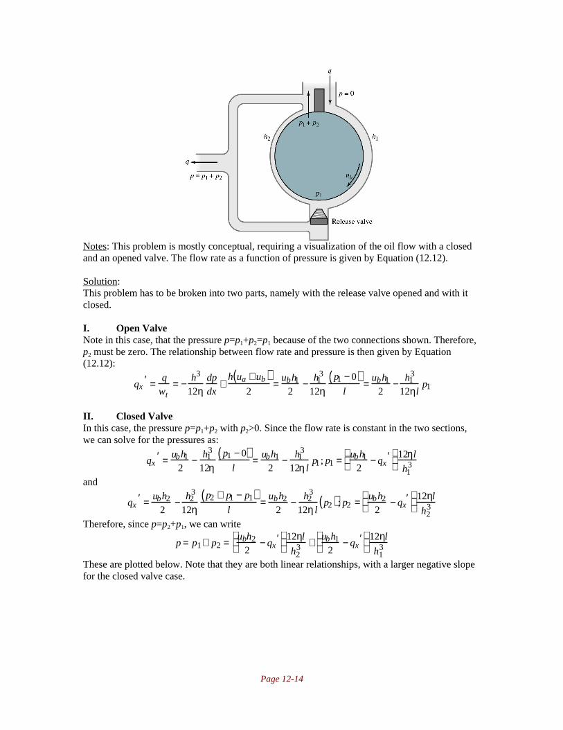
Page 12-14
Notes: This problem is mostly conceptual, requiring a visualization of the oil flow with a closedand an opened valve. The flow rate as a function of pressure is given by Equation (12.12).
Solution:This problem has to be broken into two parts, namely with the release valve opened and with itclosed.
I. Open ValveNote in this case, that the pressure p=p1+p2=p1 because of the two connections shown. Therefore,p2 must be zero. The relationship between flow rate and pressure is then given by Equation(12.12):
qx′ = q
wt= − h3
12ηdpdx
+h ua + ub( )
2= ubh1
2− h1
3
12ηp1 − 0( )
l= ubh1
2− h1
3
12ηlp1
II. Closed ValveIn this case, the pressure p=p1+p2 with p2>0. Since the flow rate is constant in the two sections,we can solve for the pressures as:
qx′ = ubh1
2− h1
3
12ηp1 − 0( )
l= ubh1
2− h1
3
12η lp1 ; p1 = ubh1
2− qx
′
12ηl
h13
and
qx′ = ubh2
2− h2
3
12ηp2 + p1 − p1( )
l= ubh2
2− h2
3
12η lp2( ) ; p2 = ubh2
2− qx
′
12ηl
h23
Therefore, since p=p2+p1, we can write
p = p1+ p2 = ubh2
2− qx
′
12ηl
h23 + ubh1
2− qx
′
12ηl
h13
These are plotted below. Note that they are both linear relationships, with a larger negative slopefor the closed valve case.

Page 12-15
12.16 A full journal bearing is used in a power plant generator in the United States. Thegenerator has four poles and delivers electricity with 60-Hz frequency. The rotor weighs30,000 kg and is equally carried by two journal slider bearings. The shaft diameter is300mm and each bearing is also 300 mm wide. The bearing and shaft surfaces are groundto a surface finish Ra=1µm. Dimension the bearings for minimum power loss andcalculate the coefficient of friction, the side-leakage ratio, and the location of theterminating pressure to find where the oil feed groove can be placed. To make sure thatthe bearings are dynamically stable, choose an eccentricity ratio of 0.82. Calculate thepower loss in the bearing.
Notes: See the notes to Problem 12.3. The film thickness is obtained from Table 12.1 given themanufacturing characteristics of the shaft. The lubricant viscosity needed to optimize the bearingis determined from Equation (12.85). While this appears on the surface to be a fruitless exercise,this allows one to select a lubricant suitable for the application. Normally one cannot get exactlythis viscosity, but close to it, and the difference in performance is usually not significant.
Solution:First of all, note that if the generator had two poles, the shaft speed would need to be 60rev/s toobtain a 60Hz signal. With four poles, the shaft speed needs to be one-half this, or 30rev/s or60πrad/s. The load is shared between two bearings, so the load Wr is
Wr=(30000kg/2)(9.81m/s2)=147kN
From Table 12.1 on page 498, if the shaft surface roughness is Ra=0.1, then the minimumallowable film thickness is h0=25µm. If the temperature rise is excessive with this value, then wewill need to modify this value. The eccentricity has been specified as 0.82, so Equation (12.89)yields
hmin
c= 1− ε ;c = hmin
1− ε= 25µm
1− 0.82= 139µm
Notice that the power loss will be minimum if the coefficient of friction is minimum, so fromFigure 12.28 on page 509, Bj=0.050 (found by the intersection of the “Minimum coefficient offriction curve and hmin/c=1-0.82=0.18). Therefore, from Equation (12.85),
Bj = η0ωbrbwt
πWr
rbc
2
;η0 =B jπWr
ωbrbwt
crb
2
= 0.050( )π 147000N( )60πrad / s( ) 0.150m( ) 0.3m( )
139µm0.15m
2
or η0=0.00234Ns/m2. The diameter to width ratio for this problem is λ=1, so from Figure 12.30,
with Bj=0.05, the coefficient of friction is found as:

Page 12-16
µ rbc
= 2.1; µ = 2.1crb
= 2.1139µm0.15m
= 0.00195
The power loss is the product of the torque and the angular velocity, orhp = µWrrbω = 0.00195( ) 147000N( ) 0.15m( ) 60πrad / s( ) = 8100Nm / s
From Figure 12.32, qs/q=0.87, and from Figure 12.34, the location of the terminating pressure isφ0=53°.
12.17 The power plant generator considered in Problem 12.16 is rebuilt and moved to Europe.The rebuilt generator has two poles and the frequency of the electricity is 50 Hz.Redimension the bearings for minimum power loss and calculate the coefficient offriction, the side-leakage ratio, and the location of the terminating pressure. Let theeccentricity ratio be 0.82 to make sure that the bearings are dynamically stable. Calculatethe power loss.
Notes: The approach is the same as in Problem 12.16. See the notes to Problem 12.16.
Solution:First of all, note that the generator has two poles, so the shaft speed needs to be 50rev/s to obtaina 50Hz signal. Therefore, we take ωb=50rev/s=100πrad/s. The load is shared between twobearings, so the load Wr is
Wr=(30000kg/2)(9.81m/s2)=147kN
From Table 12.1 on page 498, if the shaft surface roughness is Ra=1µm, then theminimum allowable film thickness is h0=25µm. If the temperature rise is excessive with thisvalue, then we will need to modify this value. The eccentricity has been specified as 0.82, soEquation (12.89) yields
hmin
c= 1− ε ;c = hmin
1− ε= 25µm
1− 0.82= 139µm
Notice that the power loss will be minimum if the coefficient of friction is minimum, so fromFigure 12.28 on page 509, Bj=0.050 (found by the intersection of the “Minimum coefficient offriction curve and hmin/c=1-0.82=0.18). Therefore, from Equation (12.85),
Bj = η0ωbrbwt
πWr
rbc
2
;η0 =B jπWr
ωbrbwt
crb
2
= 0.050( )π 147000N( )100πrad / s( ) 0.150 m( ) 0.3m( )
139µm0.15m
2
or η0=0.00140Ns/m2. The diameter to width ratio for this problem is λ=1, so from Figure 12.30,
with Bj=0.05, the coefficient of friction is found as:
µ rbc
= 2.1; µ = 2.1crb
= 2.1139µm0.15m
= 0.00195
The power loss is the product of the torque and the angular velocity, orhp = µWrrbω b = 0.00195( ) 147000N( ) 0.15m( ) 100πrad / s( ) = 13500Nm /s = 13.5kW
From Figure 12.32, qs/q=0.87, and from Figure 12.34, the location of the terminating pressure isφ0=53°.
12.18 A motor speed of 110rpm is used in a gearbox to provide a propeller speed of 275rpm.The propeller shaft diameter is 780mm, and the shaft is directly coupled to the outgoingshaft of the gearbox. The combined influence of the propeller shaft weight and the gearforces gives a 1.1MN load on the journal bearing. Dimension the journal bearing for adiameter-to-width ratio of 2, and find the viscosity and radial clearance needed to give a
Page 12-17
minimum power loss. Also, calculate the power loss in the bearing. The journal bearingdiameter is 780mm and the surface roughness Ra=3µm.
Notes: See the notes to Problem 12.16. The film thickness is obtained from Table 12.1 given themanufacturing characteristics of the shaft. The approach is very similar to Problems 12.16 and12.17.
Solution:With Ra=3µm, Table 12.1 on page 497 suggests that the minimum film thickness should
be at least 50µm (if the temperature rise is excessive, this value is increased). For this bearing,λ=2 and ωb=275rpm(2π)/60=28.8rad/s. Since the minimum power dissipation will occur with theminimum coefficient of friction, we use this curve on Figure 12.28. This intersects the λ=2 curveat Bj=0.03 and hmin/c=0.1 Therefore, c=(50µm)/0.1=500µm. From Eq. (12.85), the oil viscositywhich is needed to obtain this bearing characteristic number is
Bj = η0ωbrbwt
πWr
rbc
2
;η0 =B jπWr
ωbrbwt
crb
2
= 0.03( )π 1.1MN( )28.8rad / s( ) 0.39m( ) 0.195m( )
500µm0.39m
2
or η0=0.0778Ns/m2. From Figure 12.30 on page 510, for Bj=0.03,
µ rbc
= 1.5;µ =1.5500µm0.39m
= 0.00192
The power loss ishp=µWrrbwb=(0.00192)(1.1MN)(0.39m)(28.8rad/s)=23760Nm/s~24kW
12.19 A steam turbine rotor for a small power plant in a paper factory has two journal bearingseach carrying half the weight of a 20,000 N rotor. The rotor speed is 3000 rpm, thebearing diameters are both 120 mm, and the bearings are 120mm wide. Design thebearing with surface roughness Ra=0.6µm and minimum power loss. Calculate thecoefficient of friction, the attitude angle, the oil flow rate, and the side-leakage flow rate.Choose an eccentricity ratio of 0.82 to avoid dynamic instability.
Notes: See the notes to Problem 12.16. The film thickness is obtained from Table 12.1 given themanufacturing characteristics of the shaft. The approach is very similar to Problems 12.16through 12.18.
Solution:Note that ωb=3000rpm(2π)/60=314rad/s. From Table 12.1 for Ra=0.6 µm, the minimum allowablefilm thickness is 12.5µm (if the temperature rise is excessive, this value is increased). Therefore,from Equation (12.89),
hmin
c= 1− ε ;c = hmin
1− ε= 12.5µm
1− 0.82= 69.4µm
From Figure 12.28 for hmin/c=0.18 and λ=1, Bj=0.04, and this is close to the minimum frictioncondition, so that the neither the bearing width nor the eccentricity need to be modified. FromEquation (12.85), the required lubricant viscosity to attain this value of Bj is
Bj = η0ωbrbwt
πWr
rbc
2
;η0 =B jπWr
ωbrbwt
crb
2
= 0.04( )π 10,000 N( )314rad / s( ) 0.06m( ) 0.120m( )
69.4µm0.06m
2
or η0=0.000744Ns/m2. From Figure 12.30 on page 510,
µ rbc
= 2;µ = 2crb
= 269.4µm0.06m
= 0.00231
Page 12-18
From Figure 12.29, φ=35°. From Figure 12.31,
Q = 4.8 = 2πqrbcwtωb
;q = 4.8rbcwtωb
2π=
4.8 0.06m( ) 69.4µm( ) 0.120( ) 314rad / s( )2π
= 1.20 ×10⁻⁴m3 / s
From Figure 12.32, qs/q=0.86; qs=103x10-4m
3/s.
12.20 A full journal bearing is used in an air compressor to support a 5.2kN radial load at aspeed of 2300 rpm. The diameter-to-width ratio is 2 and SAE 50 oil is used with an inlettemperature of 100°C. The radial load per area is 1.5MPa. Determine the minimumbearing dimensions and the radial clearance for both maximum load and minimumcoefficient of friction.
Notes: This is similar to Problems 12.16 to 12.19, except that we now need to take temperatureinto account. The temperature rise will be calculated from Equation (12.91a).
Solution:I. Bearing DimensionsNote that for this bearing, λ=2, so that the radius equals the width. From Equation (12.91c) onpage 512,
Wr* = Wr
2rbwt= 1.5MPa; wt = 5.2kN
2 1 . 5MPa( )
0.5
= 0.0416m
Note also that ω=2300(2π/60)=241rad/s.
II. Clearance for Minimum FrictionWith λ=2 and using the curve for the minimum coefficient of friction, Figure 12.28 on page 509gives Bj=0.036. Therefore, from Figure 12.30, µrb/c=2. From Figure 12.31, Q=5.75. From Figure12.32, qs/q=0.95. (Note that numbers read from charts may vary slightly.) From Equation 12.91aon page 512, the temperature rise is given by (note that Wr
* is in megapascals in this equation)
∆tm =8.3Wr
* µrb / c( )Q 1 − 0.5 qs / q( )( ) = 8 . 3 1 . 5( ) 2( )
5.75( ) 1− 0.5 0.95( )( ) = 8.25°C
Therefore, the mean temperature is 100°C+4°C or 104°C. From Figure 8.13 on page 327, theviscosity of SAE 50 oil at 104°C is around η0=0.0115Pa-s. The clearance can now be calculatedfrom Equation (12.85) as:
Bj =η0ωbrbwt
πWr
rbc
2
;c =η0ωbrb
3wt
πB jWr=
0.0115Ns / m2( ) 241rad / s( ) 0.0416m( )3 0.0416m( )π 0.036( ) 5200N( )
or c=119µm.
III. Clearance for Maximum LoadWith λ=2 and using the curve for the maximum load carrying capability, Figure 12.28 on page509 gives Βj=0.35. Using the same procedure as before, we obtain the values of µrb/c=8.7 (Figure12.30), Q=4.8 (Figure 12.31), and qs/q=0.72 (Figure 12.32). Equation 12.91a gives thetemperature rise as:
∆tm =8.3Wr
* µrb / c( )Q 1 − 0.5 qs / q( )( ) = 8 . 3 1 . 5( ) 8.7( )
4.8( ) 1− 0.5 0.72( )( ) = 35°C
or the mean temperature is around 117°C. Therefore, from Figure 8.13, η0=0.0083Pa-s, so theclearance can be calculated from Equation (12.85) as

Page 12-19
Bj = η0ωbrbwt
πWr
rbc
2
;c = η0ωbrb3wt
πB jWr=
0.0083Ns / m2( ) 241rad / s( ) 0.0416m( )3 0.0416m( )π 0.35( ) 5200N( )
or c=32.4µm.
12.21 A 3.2kN radial load is applied to a 50mm diameter shaft rotating at 1500rpm. A journalbearing is used to carry the radial load. The journal bearing has a diameter-to-width ratioof 1 and is lubricated with SAE 20 oil with an inlet temperature of 35°C. Determine thefollowing:
a) Mean temperature and temperature rise in the bearingb) Minimum film thickness and its locationc) Maximum pressure and its locationd) Total and side-leakage flow rates.
Notes: See the notes to Problem 12.16. In this design problem, one less piece of information hasbeen given about the bearing than in previous problems. The solution, as discussed on page 509,is to design the bearing to have a characteristic number Bj halfway between the minimum frictionand maximum load curves. Otherwise, the problem is similar to Problem 12.20.
Solution:Note that for this problem, ω=1500(2π/60)=157rad/s. λ=1, so wt=2rb=50mm=0.050m. Therefore,from Equation (12.91c) on page 512,
Wr* = Wr
2rbwt= 3.2kN
2 0.025m( ) 0.050m( ) = 1.28MPa
From Figure 12.28 for the λ=1 curve, the midpoint between where it intersects the minimumcoefficient of friction curve and the maximum load curve is around Bj=0.15, and this value will beused for the bearing. Therefore, µrb/c=3.8 (from Figure 12.30), Q=4.4 (Figure 12.31), andqs/q=0.65 (Figure 12.32). Therefore, from Equation (12.91a),
∆tm =8.3Wr
* µrb / c( )Q 1 − 0.5 qs / q( )( ) = 8 . 3 1 . 2 8( ) 3.8( )
4.4( ) 1 − 0.5 0.65( )( ) = 13.6°C
or the mean temperature is around 25+13.6/2=42°C. From Figure 8.13, η0=0.043Pa-s. Equation(12.85) allows calculation of the clearance:
Bj = η0ωbrbwt
πWr
rbc
2
;c = η0ωbrb3wt
πB jWr=
0.043Ns / m2( ) 157rad / s( ) 0.025m( )3 0.050m( )π 0.15( ) 3200N( )
or c=59.1µm. Therefore, from Figure 12.28, hmin/c=0.44, so hmin=26µm. From Figure 12.29,φ=55° The maximum pressure is calculated from Figure 12.33:
Pmax = 0.44 = Wr
2rbwt pmax; pmax = Wr
2rbwt 0.44( ) = 3200N2 0.025m( ) 0.05m( ) 0.44( ) = 2.91MPa
From Figure 12.34, φmax=76°. Since Q=4.4, the flow can be calculated as:
Q = 2πqrbcwtωb
;q = Qrbcwtωb
2π=
4.4( ) 0.025m( ) 59.1 µm( ) 0.050m( ) 157rad / s( )2π
= 8.12 ×10⁻⁶m3 / s
Since qs/q=0.65, then the side flow rate is 0.65q=5.28x10⁻⁶m
3/s.

Page 12-20
12.22 A journal bearing has a diameter of 200 mm and a width of 50 mm while rotating at300rpm and supporting a radial load of 10kN. Calculate the oil viscosity if the maximumpressure obtained in the bearing is 5MPa and the coefficient of friction is 0.003.
Notes: See the Notes to Problem 12.16.
Solution:The angular velocity is ω=300(2π/60)=31.4rad/s. From the given data, λ=0.20m/0.05m=4 andPmax is given from Figure 12.33 on page 511 as:
Pmax = Wr
2rbwt pmax= 10,000 N
2 0.10m( ) 0.050m( ) 5 ×10⁶ N / m2( ) = 0.2
Given this value and λ=4 gives, from Figure 12.33, that Bj=0.12. Therefore, from Figure 12.30,rbµ/c=4.8. Since µ=0.003, rb/c=1600. From Equation (12.85),
Bj =η0ωbrbwt
πWr
r
c
2
;η0 =πB jwr
r
c
2
ωbrbwt
=π 0.12( ) 10 ,000N( )
1600( )2 31.4rad / s( ) 0.1m( ) 0.05m( )= 0.00937Ns / m2
12.23 A shaft is rotating at 1000rpm and is supported by two journal bearings at the two ends ofthe shaft. The bearings are lubricated with SAE 40 oil with an inlet temperature of 25°C.A 5-kN load is applied 0.5m from the left bearing where the total shaft length is 2.5m.The bearing width is 25mm, the diameter is 50mm, and the radial clearance is 0.0315mm. Determine
a) Temperature riseb) Minimum film thicknessc) Maximum pressured) Side-leakage flow ratee) Bearing power loss
Notes: See the notes to Problem 12.16. Two solutions are given. The first shows a simpleapproach of selecting a bearing characteristic number from the known information. In the secondsolution, an iterative approach is used to obtain the same result.
Solution1: Direct ApproachFrom statics, the reactions at the bearings are 4 kN and 1 kN for the left and right bearing, so theleft bearing is critical with Wr=4 kN. Also, the angular velocity is ω=1000*2π/60=104.7 sec-1.Assume it is equally important to have a bearing with both load carrying ability and low friction.Therefore, a bearing characteristic number will be chosen from Figure 12.28 between the extremevalues. For λj=2 and minimum friction, Bj=0.03. For λj=2 and maximum load carrying capability,Bj=0.35. Therefore, we take the average value of 0.19, or around 0.2. Therefore, from Figure12.28, ε=0.68, and hmin/c=0.32. From Figure 12.30, rbµ/c=6. From Figure 12.31, Q=5.4, and fromFigure 12.32, qs/q=0.82. From Equation (12.91c),
Wr* =
Wr
2rbwt=
4kN
2 0.025m( ) 0.025m( )= 3.2MPa
From Equation (12.91a), the mean temperature rise is
∆tm =8.3 Wr
* rb / c( )µQ 1 − 0.5 qs / q( )( ) =
8.3 3.2( ) 6( )5.4( ) 1 − 0.5 0.82( )( ) = 50°C

Page 12-21
Therefore, the mean temperature istm=ti+0.5∆tm=25°C+0.5(50°C)=50°C
From Figure 8.13, the viscosity of the oil is read as 0.065 Ns/m2. Therefore,hmin
c= 0.32;hmin = 0.32c = 0.32( ) 0.0315mm( ) = 0.010mm = 10µm
From Figure 12.33, Pmax=0.33, so
Pmax = Wr
2rbwt pmax; pmax = Wr
2rbwtPmax= 4000N
2 0.025m( ) 0.025m( )0.33= 9.7MPa
Similarly, it can be calculated that q=1.77x10⁻⁶m
3/s, qs=0.79q=1.40x10
-6m
3/s, and
µ=6c/rb=0.0076. The power loss ishp = µWrrbω b = 0.0076( ) 4000N( ) 0.025m( ) 104.7rad / s( ) = 79.6W
Solution2: Iterative ApproachFrom statics, the reactions at the bearings are 4 kN and 1 kN for the left and right bearing, so theleft bearing is critical with Wr=4 kN. Also, the angular velocity is ω=1000*2π/60=104.7 sec-1.The bearing characteristic number is:
Bj = η0ωbrbwt
πwr
rbc
2
= 3.29η0
The bearing diameter to width ratio is 2. The approach is to then assume a temperature rise andthen to evaluate the bearing and determine if the temperature rise that results matches the initialguess. The following table can be constructed:
Quantity ∆tassumed=10°C ∆tassumed=50°CAverage temp. = 25°C+∆t/2 30 50
η0 (From Fig. 8.13) 0.23 Ns/m2 0.065 Ns/m2
Bj=3.29η0 0.69 0.21rbµ/c (From Fig. 12.30) 10.5 6
Q (Fig. 12.31) 4.8 5.05qs/q (Fig. 12.32) 0.61 0.79
∆tcalc 83.6 (higher than initial guess) 52°C (very close to initial)Therefore, the performance parameters are as read from the assumed temperature rise of 50°C.Therefore, from Figure 12.28,
hmin
c= 0.32;hmin = 0.32c = 0.32( ) 0.0315mm( ) = 0.010mm = 10µm
From Figure 12.33, Pmax=0.33, so
Pmax = Wr
2rbwt pmax; pmax = Wr
2rbwtPmax= 4000N
2 0.025m( ) 0.025m( )0.33= 9.7MPa
Similarly, it can be calculated that q=0.249x10⁻⁶m
3/s, qs=0.79q=0.196x10
-6m
3/s, and
µ=6c/rb=0.0076. The power loss ishp = µWrrbω b = 0.0076( ) 4000N( ) 0.025m( ) 104.7rad / s( ) = 79.6W
12.24 The infinitely wide slider bearing shown in sketch h has parallel surfaces, squeeze speedw across the oil film thickness h, and bearing length l. Find the bearing damping constantB=-∂Wz/∂w, where Wz is the bearing load per width. Use the Reynolds equation forsqueeze motion.
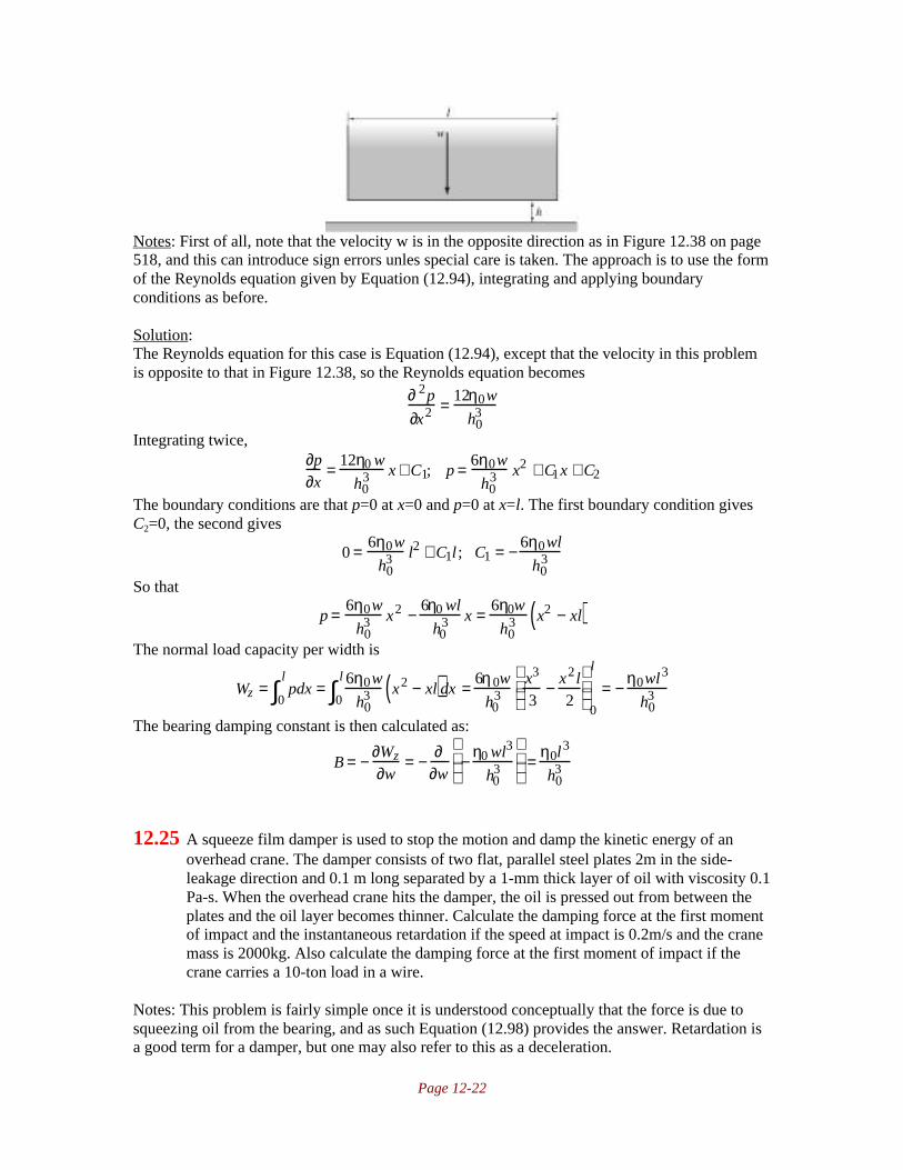
Page 12-22
Notes: First of all, note that the velocity w is in the opposite direction as in Figure 12.38 on page518, and this can introduce sign errors unles special care is taken. The approach is to use the formof the Reynolds equation given by Equation (12.94), integrating and applying boundaryconditions as before.
Solution:The Reynolds equation for this case is Equation (12.94), except that the velocity in this problemis opposite to that in Figure 12.38, so the Reynolds equation becomes
∂ 2p
∂x2 = 12η0w
h03
Integrating twice,∂p∂x
= 12η0 w
h03 x + C1; p = 6η0w
h03 x2 + C1x + C2
The boundary conditions are that p=0 at x=0 and p=0 at x=l. The first boundary condition givesC2=0, the second gives
0 = 6η0w
h03 l2 + C1l ; C1 = − 6η0wl
h03
So that
p = 6η0w
h03 x2 − 6η0 wl
h03 x = 6η0w
h03 x2 − xl( )
The normal load capacity per width is
Wz = pdx0
l
∫ = 6η0w
h03 x2 − xl( )0
l
∫ dx = 6η0w
h03
x3
3− x2 l
2
0
l
= − η0wl3
h03
The bearing damping constant is then calculated as:
B = − ∂Wz
∂w= − ∂
∂w− η0 wl3
h03
=
η0l3
h03
12.25 A squeeze film damper is used to stop the motion and damp the kinetic energy of anoverhead crane. The damper consists of two flat, parallel steel plates 2m in the side-leakage direction and 0.1 m long separated by a 1-mm thick layer of oil with viscosity 0.1Pa-s. When the overhead crane hits the damper, the oil is pressed out from between theplates and the oil layer becomes thinner. Calculate the damping force at the first momentof impact and the instantaneous retardation if the speed at impact is 0.2m/s and the cranemass is 2000kg. Also calculate the damping force at the first moment of impact if thecrane carries a 10-ton load in a wire.
Notes: This problem is fairly simple once it is understood conceptually that the force is due tosqueezing oil from the bearing, and as such Equation (12.98) provides the answer. Retardation isa good term for a damper, but one may also refer to this as a deceleration.

Page 12-23
Solution:The speed at impact is the initial change in the film thickness, so the load support at impact iscalculated from Equation (12.98) as
Wz = wtWz′ = −
w tη0l3
h03
∂h0
∂t=
2m( ) 0.1Ns / m2( ) 0.1m( )3
0.001m( )3 0.2m / s( ) = 40kN
The instantaneous retardation is Wz/ma, or 40kN/2000kg=20m/s2.
The initial damping force does not depend on the mass, only on the contact velocity, so the forcewould still be 40kN.
12.26 The circular hydrostatic thrust bearing shown in sketch i has inner radius ri and outerradius ro, a constant oil film thickness h, and a constant oil flow rate q. The bearing loadis P and the oil viscosity is η. Find the bearing stiffness coefficient cs=-∂P/∂h.
Notes: The approach in Example 12.8 starting on page 522 is very helpful for this problem. Thebasic problem is to obtain the pressure distribution, integrate the pressure to get the load, thentake the derivative with respect to the film thickness to get the stiffness coefficient.
Solution:Using equation (e) from Example 12.8 on page 524 gives the volumetric flow rate in terms of thereservoir pressure pr. Solving this for pr gives
q = − πh3pr
6η0 ln ri / ro( ) ; pr = −6qη0 ln ri / ro( )
πh3
The pressure, given by equation (b) on the same page, is
p = prln r / ro( )ln ri / ro( ) = −
6qη0 ln ri / ro( )πh3
ln r / ro( )ln ri / ro( ) = − 6qη0
πh3 lnrro
=
6qη0
πh3 ln3ri − ln r( )where we have already used the relationship ro=3ri. The normal load is then given by
Wz = πri2 pr + p 2πr( )dr
ri
3ri∫ = πri2pr + 6qη0
πh3 ln3ri − ln r( )
2πr( )dr
ri
3ri∫
Wz = πri2pr + 12η0q
h3ri
2
2ln
1
3
+ 2ri
2
= 6ri2η0q ln 3( )
h3 + 12η0q
h3ri
2
2ln
1
3
+ 2ri
2
= 24η0qri2
h3
Taking the derivative with respect to film thickness to get the stiffness coefficient:
cs = −∂Wz
∂h= −
∂∂h
24η0qri2
h3
=
72η0qri2
h4

Page 12-24
12.27 A circular hydrostatic thrust bearing, shown in sketch j, has a constant oil film thicknessh. A central lubricant reservoir, whose height is much larger than the oil film thickness, isfed by a liquid with pressure pr. Find the pump power needed if the bearing carries loadP. Given that ri=27mm, η=0.00452Ns/m
2, h=0.120mm, ro=200mm, P=3.08x10
4N.
Notes:The approach in Example 12.8 starting on page 522 is very helpful for this problem. Theapproach is to determine the required reservoir pressure and the flow rate. The required pumppower is the product of the pressure and flow rate.
Solution:The reservoir pressure can be calculated from Equation (f) from Example 12.8 on page 525:
Wz =πpr ro
2 − ri2( )
2 l nro / ri( ) ; pr =2Wz ln ro / ri( )
π ro2 − ri
2( ) = 2 30.8kN( ) ln 2 0 0 / 2 7( )π 0.2m( )2 − 0.027m( )2( ) = 106 N / m2
The flow rate is obtained from equation (e) from Example 12.8 on page 524:
q = πh3pr
6η0 ln ro / ri( ) =π 0.000120m( )3 106N / m2( )
6 0.00452 Ns / m2( ) ln 2 0 0 / 2 7( )= 1.0×10⁻⁴ m3 / s
The power required is the product of pressure and flow rate:
hp = prq = 106 N / m2( ) 1.0 ×10⁻⁴ m3 / s( ) =100W
12.28 When some early satellites were launched, the bearings used in gyroscopes were highfrequency squeeze film gas bearings consisting of two flat, circular disks vibratingagainst each other. The lubricating gas film is described by
h = hm + a sinωtsin ωt
where the vibration frequency w is extremely high and the amplitude can be expressed asa=0.8hm. Calculate the bearing load carrying capacity as a function of the air pressure inthe satellite and the bearing diameter when ω is extremely high and the gas is adiabaticwith the pressure-volume relationship
pV1.4 = pmVm1.4 = constant
Notes: This problem requires one to calculate the mean and extremes (minimum and maximum)of volume between the plates and then use the gas law given to determine the pressure. The veryhigh frequency is required, or else there will be large side flow and the mass of gas inside thebearing will vary.

Page 12-25
Solution:The gas volume between the plates is
V = πr2 hmean ± a( ) = πr2hmean 1± 0.8( )The maximum pressure occurs at the minimum volume, so
pmaxVmin1.4 = pmeanVmean
1.4 ;pmax= pmeanVmean
Vmin
1.4
= pmean1
0.2
1.4
= 9.518pmean
Similarly the minimum pressure is
pminVmax1.4 = pmeanVmean
1.4 ;pmin= pmeanVmean
Vmax
1.4
= pmean1
1.8
1.4
= 0.4392 pmean
The mean load carrying capacity over one vibration cycle is
Wz = pmax + pmin
2− pmean
A = 9.518 + 0.4392
2−1
pmean
πd2
4
= 3.125d 2pmean
12.29 A flat, circular, hydrostatic air bearings has an outer diameter of 160mm and a 5-mm-deep recess from the 50mm diameter to the bearing center. The air pressure in the recessis 2MPa, and the pressure around the outside of the bearing is 0.1MPa. Determine thepressure distribution in the bearing if 0.3 kg of air is pumped through the bearing persecond. The air density is 1 kg/m
3 at atmospheric pressure and the air viscosity is 18.2 x
10-6 Pa-s at 22°C. Also, calculate the air film thickness and the friction torque if the
bearing rotates at 8000rpm.
Notes: This approach is similar to that for a liquid lubricant, however the ideal gas law is used torelate density to pressure. Familiarity with Example 12.8 starting on page 522 is helpful for thisproblem. Note that Equation (12.12) gives volume flow rate; mass flow rate is the product ofdensity and volume flow rate.
Solution:I. Pressure DistributionThe radial flow in a hydrostatic bearing is given by Equations (d) and (e) of Example 12.8 onpage 524 as
q = 2πrqr′ = 2πr − h0
3
12η0
dpdr
The mass flow for a compressible gas in a hydrostatic bearing is
dma
dt= ρq = ρ2πr − h0
3
12η0
dpdr
= − 2πrρh0
3
12η0
dpdr
The ideal gas law says that ρ=p/RT, where T is the absolute temperature and R is the gas constant.Substituting this for ρ gives
dma
dt= − 2πrph0
3
12η0RTdpdr
All of these are constant except for p and r. Therefore, we can write
dma
dt= − 2πrph0
3
12η0RTdpdr
;rpdpdr
= − dma
dt6η0RT
πh03 = C1

Page 12-26
where C1 is a constant. Therefore we can separate variables and integrate:
pdp = C1drr
; pdpp
pa∫ =C1drrr
ry∫ ;pa
2 − p2
2= C1 ln
ryr
where pa is the atmospheric pressure, ry is the radius at the edge of the bearing, and p is thepressure at radius r. The boundary condition used to evaluate C1 is that the pressure equals thereservoir pressure at the inner radius, or p=pr at r=ri. Therefore
pa2 − pr
2
2= C1 ln
ryri
;C1 = pa
2 − pr2
2 l nry / ri( )so that the pressure distribution is
pa2 − p2
2= pa
2 − pr2
2ln ry / ri( ) lnryr
; p = pa
2 +pr
2 − pa2( ) ln ry / r( )
ln ry / ri( )
1 / 2
II. Film Thickness and TorqueWe can get the film thickness from the mass flow rate. Note that
dpdr
= ddr
pa2 +
pr2 − pa
2( ) ln ry / r( )2ln ry / ri( )
1 / 2
= − 12
pa2 +
pr2 − pa
2( )ln ry / r( )ln ry / ri( )
−1 / 2pr
2 − pa2( )
ln ry / ri( )rry
ry
r2
= − 1p
pr2 − pa
2( )2r ln ry / ri( )
So that the mass flow is given by
dma
dt= − 2πrρh0
3
12η0
dpdr
= 2πrρh03
12η0
1p
pr2 − pa
2( )2r ln ry / ri( ) = 0.3kg / s
Solving for h0 and evaluating this at the outer radius so that p=patm, ρ=1kg/m3, r=ry=0.08m and
η0=18.2x10⁻⁶Pas as given yields
2πrρh03
12η0
1
p
pr2 − pa
2( )2r ln ry / ri( ) = 0.3kg / s;h0
3 =12η0 p ln ry / ri( ) 0.3kg / s( )
πρ pr2 − pa
2( )=
12 18.2 × 10⁻⁶ Ns / m2( ) 0.1MPa( ) ln 8 0 / 2 5( ) 0.3kg / s( )π 1kg / m3( ) 2MPa( )2 − 0.1MPa( )2( ) = 6.08 ×10 -13m3
or h0=84.7µm. Note that the angular velocity is ω=8000(2π/60)= 838rad/s. The torque for thisbearing is
T = η rωh
2πr( )rdr
ri
ry∫ = 2πωηh
r3drri
ry∫ =πωη ry
4 − ri4( )
2h
=π 838rad / s( ) 18.2 × 10⁻⁶ Ns / m2( ) 0.08m( )4 − 0.025m( )4( )
2 84.7µm( ) = 0.0115Nm

Page 13-1
13 • Rolling-Element Bearings
13.1 In roller bearings the load is carried by rollers and the contacts between rollers and racesare rectangular. The bearing macrogeometry determines which type of load can becarried by the bearing: radial, axial or moment loads. Find which type of load can becarried by the different types of bearing shown in Tables 13.4 and 13.5
Solution:Referring to the nomenclature in Tables 13.4 and 13.5, N-type bearings can only carry a radialload. The outer ring must be guided in relation to the inner ring by some other bearing on theshaft, since even minute elastic deformation of the shaft will make the bearing wander axiallyrelative to the outer ring.
NU-type bearings has the same behavior as the N-type. The only difference is that theroller set is guided by the inner ring of the N-bearing and by the outer ring for the NU-bearing.
NJ-type bearings can carry large radial and small axial loads and impact loads in onedirection but separates like a NU-type in the opposite direction.
NUP-type bearings can carry large radial loads and small axial loads and impact loads inboth axial directions. NUP bearings do not necessarily need to have another bearing on the shaftfor axial guidance.
The bearings shown in Table 13.5 can carry both axial and radial loads, all except thrustbearings which can carry only axial loads in both directions. Roller bearings are all stiffer thanball bearings for the same size. Spherical roller bearings are insensitive to misalignment.
13.2 Too high a power loss can be a problem in extremely high-speed applications of angularcontact bearings. A large part of that power loss comes from the churning of the oil whenthe rolling balls displace the oil and splash it around the bearing. It is therefore importantnot to collect too much oil in the rolling tracks. For a duplex arrangement with thelubricating oil passing through both bearings for cooling, find if a back-to-back or face-to-face arrangement is preferred from a low-power-loss point of view.
Solution:A back-to-back arrangement is preferred from a power loss point of view. The centrifugal forceacting on the oil will fill the volume between the rows of the balls much easier in a face-to-facearrangement than for a back-to-back arrangement.
13.3 A deep-groove ball bearing with itsdimensions is shown in sketch a. Alldimensions are in millimeters. Also, n=11,d=21/32in = 16.67 mm. Find the maximum ballforce and stress as well as the relativedisplacement of the race. The static radial loadcapacity of the bearing is 36,920N. Assume theballs and rings are made of steel.

Page 13-2
Notes: The stress equation is Equation (8.23), which requires calculation of the geometricproperties emphasized in this chapter. The deflections are calculated from Equation (8.27)separately for the ball and inner and outer ring contacts. The total deflection is the sum of the twodeflections.
Solution:I. Maximum Ball Force and StressThe maximum ball force can be calculated from either equations (13.47) or (13.50). 13.50 is moreconservative and will be used here since there is no indication that there is an imperativeperformance requirement. Equation (13.50) gives the maximum ball force as:
wz =n wz( )max
5; wz( )max = 5wz
n= 5 36 ,920N( )
11= 16,782 N
The stress or pressure is given by equation (8.23), but before we can evaluate this equation, wemust calculate the contact ellipse diameters given by Equations (8.25) and (8.26), which needinformation first as well. Note however that the stress will be larger on the inner race. This isbecause all of the radii are the same except for rbx, which is smaller on the inner race than theouter race. Therefore, the contact area will be smaller on the inner race and will give a largerstress. On the inner race, we can obtain the following values from the sketch:
rax=ray=16.67mm/2=8.335mm. rbx=83mm/2=41.5mm. rby=-8.63mmNote that rby is negative and rbx is positive on the inner race.From Equations (8.17) and (8.18),
1Rx
= 1rax
+ 1rbx
= 18.335mm
+ 141.5mm
; Rx = 6.941mm
1Ry
= 1ray
+ 1rby
= 18.335mm
− 18.63mm
; Ry = 243.8mm
Therefore, from Equation (8.15),1R
= 1Rx
+ 1Ry
= 16.941mm
+ 1243.8mm
;R = 6.748mm
from Equation (8.19), αr=Ry/Rx=243.8/6.941=35.12. From Equation (8.24), ke=αr2/π
= 35.122/π
=9.638. From Table 8.6,F is calculated as F=π/2+(π/2-1)lnαr=3.602, and E is 1+(π/2-1)/αr=1.016.Also, from equation (8.2), and noting that for steel E=207GPa and ν=0.3 as tabulated on theinside front cover,
′ E = 2
1−νa2
Ea+ 1−ν b
2
Eb
= E
1 −ν2 = 207GPa
1 − 0.32 = 227.5GPa
Therefore, from Equations (8.25) and (8.26)
Dy = 2
6keEWR
π ′ E
1 / 3
= 26 9.638( ) 1.016( ) 16 ,782N( ) 0.006748m( )
π 227.5GPa( )
1 / 3
= 8.974mm
Dx = 2
6EWR
πke ′ E
1 / 3
= 26 1.016( ) 16,782N( ) 0.006748 m( )
π 9.638( ) 227.5GPa( )
1 / 3
= 0.9311 mm
Therefore, Equation (8.23) gives the maximum stress as
σmax = 6WπDxDy
= 6 1 6 , 7 8 2N( )π 0.008974 m( ) 0.0009311m( ) = 3.836GPa

Page 13-3
II. Total DeflectionWe have to calculate the deflection on the inner and outer races, then take their sum to get thetotal deflection. The inner race is easier, since the geometric properties have already beencalculated. Equation (8.27) gives
δmax = F9
2ERW
πke ′ E
2
1 / 3
= 3.602( ) 92 1.016( ) 0.006748m( )
16,782 Nπ 9.638( ) 227.5GPa( )
2
1 / 3
which is evaluated as δmax=56.68µm on the inner race.On the outer race, we have to use the same equations to get the geometrical factors
needed to get the deflection. Note from the figure that on the outer race, rbx=-116.3/2=-58.15mm,all other radii are the same. Therefore Ry is still 243.8mm, but Rx is now
1
Rx=
1
rax+
1
rbx=
1
8.335mm−
1
58.15mm;Rx = 9.730mm
Therefore, from Equation (8.15),1
R=
1
Rx+
1
Ry=
1
9.730mm+
1
243.8mm;R = 9.355mm
from Equation (8.19), αr=Ry/Rx=243.8/9.730=25.06. From Equation (8.24), ke=αr2/π
= 25.062/π
=7.773. From Table 8.6,F is calculated as F=π/2+(π/2-1)lnαr=3.410, and E is 1+(π/2-1)/αr=1.023.Therefore, from Equations (8.25) and (8.26)
Dy = 26ke
2 EWR
π ′ E
1 / 3
= 26 7.773( )2 1.023( ) 16,782 N( ) 0.009355m( )
π 227.5GPa( )
1 / 3
= 8.670mm
Dx = 2
6EWRπke ′ E
1 / 3
= 26 1.023( ) 16,782 N( ) 0.009355 m( )
π 7.773( ) 227.5GPa( )
1 / 3
=1.115mm
Equation (8.27) gives
δmax = F9
2ERW
πke ′ E
2
1 / 3
= 3.410( ) 92 1.023( ) 0.009355m( )
16,782 Nπ 7.773( ) 227.5GPa( )
2
1 / 3
which is evaluated as δmax=55.41µm for the outer race.The total displacement is δ=δi+δo=55.41µm+56.68µm=112.1µm=0.1121mm.
13.4 In determining how large the contact areas are in a rolling-element bearing at a certainload, the geometry of each bearing part must be known. For a deep-groove ball bearingthe width-to-length ratio of the contact area is given by the race conformity as expressedin Eq. (13.3). Calculate the race conformity for both the inner and outer race contactswhen the ball diameter is 17mm and the radii of curvature in the axial direction are 8.840mm for the inner race and 9.180 mm for the outer race. Also, calculate the free contactangle and endplay when the diametral clearance is 136µm.
Notes: This problem is straightforward, requiring direct application of Equations (13.3), (13.4),(13.7) and (13.10) for solution.
Solution:The race conformity is given by Equation (13.3). For the inner race,
Rri = rid
= 8.840mm17mm
= 0.52

Page 13-4
and for the outer race
Rro = rod
= 9.180mm17mm
= 0.54
The distance between race curvature centers is given by Equation (13.4) ascr=ro+ri-d=9.180+8.840-17=1.02mm
From Equation (13.7) the free contact angle is
cosβ f = 1− cd
2cr;β f = cos−1 1 − cd
2cr
= cos−1 0.136mm
2 1.02mm( )
= 21.04°
Therefore the endplay, given by Equation (13.10) isce=2crsinβf=2(1.02mm)sin21.04°=97.65µm.
13.5 In a spherical roller bearing the inner radius of the outer race (the radius to the sphericalsurface) is 175 mm. The roller diameter is 41 mm and the crowning radius is 168mm.The diametral play is 0.3mm for the outer race. Calculate the race conformity, the freeendplay, and the free contact angle when the angle between each roller center and thebearing center plane is 12°.
Notes: This problem is straightforward, relying on sections 13.4.2.2 and 13.4.2.3 on pages 560 -561.
Solution:For roller bearings, the race conformity is obtained from the equation on page 560 as
Rr = ro2rr
= 175mm2 1 6 8mm( ) = 0.5208
From the second equation on page 561, the free contact angle is
β = cos−1 1− cd
2ro
cos γd
= cos−1 1− 0.330mm2 175mm( )
cos12°
=12.25°
The free endplay is thence=2ro(sinβ-sinγd)+cdsinγd=2(175mm)(sin12.25°-sin12°)+(0.330mm)sin12°=1.562mm
13.6 For a cylindrical roller bearing the separator has the form of a cylinder with outerdiameter of 80 mm, inner diameter of 74mm, and width of 16mm. Fourteen 13-by-13 mmrectangular pockets are evenly distributed around the circumference of the separator. Ineach pocket is a 12.5- by 12.5 mm cylindrical roller. The inner-race outer diameter is65mm and the outer race inner diameter is 90mm. How fast can the bearing inner racerotate before the polyester separator fails? Use a safety factor of 10 and the lowest valuesin Table A.4 for polyester.
Notes: The approach is to use kinematics to obtain a relationship for the cage velocity, thenobtain the stresses due to centripetal forces as a function of this angular velocity.
Solution:A sketch of the separator and the forces acting on the separator are shown below. From Table A-4, the lowest density of polyester is 1040kg/m
3 and the lowest ultimate strength is 41MPa. Note
that the clearance between the inner and outer race is 12.5mm, and this is the maximum height ofthe separator. The total mass of the separator is

Page 13-5
m = ρV = ρ π4
do2 − d i
2( ) ts − nlwtg
= 1040kg / m3( ) π4
0.08m( )2 − 0.074m( )2( ) 0.016m( )− 14( ) 0.013m( ) 0.013m( ) 80mm − 74mm
2
= 0.004694kg
The height of the separator is 3mm, the width of each leg is (16mm-13mm)/2=1.5mm, so the areaof each leg is 4.5mm
2 or for the two legs 9x10
-6m
2.
The centripetal force is given by
2F = v2
rdma cosφ =
−π /2
π /2
∫ v2mar cosφdφ2πr2 = mav2
πr−π / 2
π / 2
∫The sketch to the right shows the velocity components of a rollerand the races. Assuming pure rolling,
ωi − ωc( )ri = ωcro ;ωc = ω iriro + ri
= ω i32.577.5
= 0.4194ωi
The cage mean velocity is then
v = rmeanωc = 0.08m +0.074m( )4
0.419ω i = 0.01615ω i
The stress is given by
σ = FA
= mav2
2πrA=
0.004694kg( ) 0.01615ω i( )2( )2π 0.08m + 0.074 m
4
9 ×10⁻⁶m2( )
= 0.5620kg / m3( )ωi2
Setting this equal to the allowable stress yields ωi=2701rad/s, or 25,790 rpm. Speeds above25,790 rpm will overstress the separator.
13.7 For the cylindrical roller bearing in Problem 13.6 calculate the sliding speed at thecontact between the rollers and the separator if the inner race rotates at 10,000rpm.
Notes: This problem uses Equation (13.28) for solution, and also assumes that the outer race isstationary if the inner race is moving. This could be left as a variable in the solution if desired.
Solution:From Problem 13.6, de=ro+ri=45+32.5=77.5mm, d=12.5mm. The inner race angular velocity isωi=10,000(2π/60)=1047rad/s. If ωo=0, Equation (13.28) gives the angular speed of the rollers as
ωb = de
2dωi 1− d cosβ
de
= 77.5mm2 12.5mm( ) 1047rad / s 1 − 12.5mm
77.5mm
= 2723rad / s
where we have taken β=0. This is the angular speed of the rollers, so the sliding speed at theseparator is ub=ωbrb=(2723rad/s)(0.0125m/2)=17.02m/s.
Page 13-6
13.8 A separator for a cylindrical roller bearing is made of nylon 66 with an ultimate strengthof 80MPa at 20°C. At the maximum service temperature of 260°C the ultimate strengthfalls to 1 MPa. The cage material can withstand a bearing speed of 16,000 rpm at 50°C.What speed can it withstand at 150°C if the ultimate strength varies linearly withtemperature?
Notes: This problem requires calculation of allowable stresses at the temperatures of interest, andalso the realization that stress is proportional to velocity squared. This is demonstrated in Problem13.6, and is to many students intuitive.
Solution:If the strength varies linearly with temperature, then at 50°C, the strength is
S50°C = 80MPa − 80MPa − 1MPa( )260°C − 20°C( ) 50°C − 20°C( ) = 70.12 MPa
and at 150°C, the strength is
S150°C = 80MPa − 80MPa −1MPa( )260°C − 20°C( ) 150°C − 20°C( ) = 37.21MPa
As shown in Problem 13.6, the stress is proportional to the velocity squared, so
S50°C
S150°C=
N50°CN150°C
2
;N150°C = N50°CS150°C
S50°C
0.5
= 16,000rpm( ) 37.2170.12
0.5
= 11,660rpm
13.9 A deep groove ball bearing has a nylon 66 snap cage that is snapped in between the ballsafter they have been mounted. If the arms separating the balls have a square 3 by 3 mmcross section and are 12mm long, calculate how fast a 100mm diameter cage can rotatewithout overstressing the ball separating arms. The maximum allowable bending stress is20MPa.
Notes: The load on the cantilever arises from the inertia, and is distributed along its length.
Solution:The average density of Nylon66 is 1140kg/m
3 from Table A4. The maximum stress in a
cantilever having a constant load intensity along its length is
σ =Mc
I=
ρV rω2( ) l
2c
1
122c( )4
=3ρl2rω2
2c
where ρ is the density, l is the cantilever length, r is the separator radius, ω is the angular velocityand c is one-half the cantilever cross section height. Substituting values and solving for theangular velocity is
σ = 3ρl2rω2
2c;ω = 2σc
3ρl2r= 2 20MPa( ) 0.0015m( )
3 1140kg / m3( ) 0.012m( )2 0.1m / 2( )= 1561rad / s
or ω=14,910rpm.

Page 13-7
13.10 Using the results from Problem 13.3, determine the minimum film thickness and the filmparameter for the ball-inner race contact and the ball-outer race contact. The inner racerotates at 20,000 rpm and the outer race is stationary. The absolute viscosity at p=0 andbearing effective temperature is 0.04 Pa-s. Also, the viscosity-pressure coefficient is 2.3 x10
-8 m
2/N. The rms surface roughnesses are 0.0625µm for the balls and 0.175µm for the
races.
Notes: This problem uses Equation (13.72) for the film thickness, which requires calculation ofthe dimensionless parameters associated with this equation. The film parameter is given byEquation (8.8) on page 593. It is useful to assume that the ball is moving by pure rolling so thatthe velocities can be calculated from Equations (13.30) and (13.32).
Solution:I. Common parametersFrom Problem 13.3, we use the values rax=ray=16.67mm/2=8.335mm. rbx=83mm/2=41.5mm. rby=-8.63mm, d=16.67, Pmax=16,782N, E’=227.5GPa, and ke=9.638 and 7.773 for the inner and outerrace contacts, respectively. From the figure associated with Problem 13.3, we obtain de=99.6mm.We then verify that the contact angle is essentially zero. From Equation (13.14),
rbx = de − d cosβ2 c o sβ
;cos β = de
2rbx + d= 99.6mm
2 41.5mm( )+ 16.67 mm;β = 0.00064°
Since the outer race is stationary, ωo=0. The inner race angular velocity is ωi=20,000(2π/60) =2094rad/s. For pure rolling, u=uai=ubi=|uao|=|ubo|, so Equation (13.30) yields
u =de ωi −ωo( )
41− d 2 cos2 β
de2
=
0.0996m( ) 2094rad / s( )4
1− 16.672
99.62
= 50.6m / s
II. Ball-Inner RaceWe intend to use Equation (13.72), which requires calculation of W, U, and G, since ke is
known to be 9.638. For the inner race contact with the ball, it was determined in Problem 13.3that Rx=6.941mm. The dimensionless load parameter is given by Equation (13.69) on page 583 as
W = P
′ E Rx2 = 16,782 N
227.5GPa( ) 0.006941m( )2 = 0.001531
The dimensionless speed parameter is given by Equation (13.70) as
U = η0u′ E Rx
=0.04 Ns / m2( ) 50.68m / s( )227.5GPa( ) 0.006941m( ) = 1.284 ×10⁻⁹
The dimensionless materials parameter is
G = ξ ′ E = 2.3 ×10⁻⁸m2 / N( ) 227.5GPa( ) = 5233
Therefore, Equation 13.72 gives the minimum film thickness as
Hmin = hminRx
= 3.63U0.68G0.49W −0.073 1− e −0.68ke( )= 3.63 1.284×10⁻⁹( )0.68
52330.490.001531−0.073 1 − e−0.68 9.638( )( ) = 0.0003474
or hmin=2.411µm. The film parameter, from Equation (8.8) is
Λ = hmin
Rqa2 + Rqb
2( )1 / 2 = 2.411µm
0.0625µm( )2 + 0.175µm( )2( )1 / 2 = 12.97
III. Ball-Outer Race

Page 13-8
We use the same approach as in part II, but with Rx=9.730mm and ke=7.773. The dimensionlessload parameter is given by Equation (13.69) on page 583 as
W = P
′ E Rx2 = 16,782 N
227.5GPa( ) 0.009370m( )2 = 7.792 ×10⁻⁴
The dimensionless speed parameter is given by Equation (13.70) as
U = η0u′ E Rx
=0.04 Ns / m2( ) 50.68m / s( )227.5GPa( ) 0.00973 m( ) = 9.158×10⁻¹⁰
The dimensionless materials parameter is still G=5233, so Equation 13.72 gives the minimumfilm thickness as
Hmin = hmin
Rx= 3.63U0.68G0.49 W−0.073 1− e−0.68ke( ) = 0.0002890
or hmin=2.803µm. The film parameter, from Equation (8.8) is
Λ = hmin
Rqa2 + Rqb
2( )1 / 2 = 2.803µm
0.0625µm( )2 + 0.175µm( )2( )1 / 2 = 15.08
13.11 A 0.4in diameter ball is loaded against a plane surface with 25lbf. The other parametersareRms surface finish of ballRms surface finish of planeAbsolute viscosity at p=0 and bearing effective temperatureViscosity-pressure coefficientModulus of elasticity for ball and planePoisson’s ratio for ball and planeFilm parameter
2.5 µin.7.5 µin.
6x10⁻⁶lb-s/in
2
1.6x10⁻⁴in
2/lb
3x10⁷psi
0.33.0
Determine the following:a) Minimum film thicknessb) Mean velocity necessary to achieve the above film thicknessc) Contact dimensionsd) Maximum pressuree) Maximum deformation
Notes: This is similar to problems 13.3 and 13.10, using the same equations and approaches.
Solution:I. Minimum Film ThicknessSince the film parameter and roughnesses are known, the minimum film thickness is obtainedfrom Equation (8.8) as
Λ = hmin
Rqa2 + Rqb
2( )1 / 2;hmin = Λ Rqa2 + Rqb
2( )1 / 2= 3.0( ) 2.5µin( )2 + 7.5µin( )2( )1 / 2
= 23.72µ in
II. Required VelocityThe velocity is obtained from Equation (13.72) by solving for the dimensionless velocityparameter, then solving this parameter for velocity. First we note that since rax=ray=0.2in,rbx=rby=∞ (flat plane). From Equations (8.17) (8.18) and (8.15),
1
Rx=
1
rax+
1
rbx=
1
0.2 in+
1
∞;Rx = 0.2in

Page 13-9
1
Ry=
1
ray+
1
rby=
1
0.2in+
1
∞; Ry = 0.2in
1R
= 1Rx
+ 1Ry
= 10.2 in
+ 10.2 in
;R = 0.1in
Therefore, from Equation (8.19) on page 329, αr=Ry/Rx=1, and since from Equation (8.24)ke=αr
2/π, ke is also 1. From Equation (8.2),
′ E = 2
1−νa2
Ea+ 1−ν b
2
Eb
= E
1 −ν2 = 3×10⁷ psi
1 − 0.32 = 32.97Mpsi
The dimensionless load parameter is given by Equation (13.69) on page 583 as
W =P
′ E Rx2 =
25lb
32.97Mpsi( ) 0.2 in( )2 = 1.896 × 10⁻⁵
The dimensionless materials parameter is
G = ξ ′ E = 1.6×10⁻⁴ in2 / lb( ) 32.97Mpsi( ) = 5275
Solving Equation 13.72 for the velocity parameter U gives
Hmin = hmin
Rx= 23.72µ in
0.2 in= 3.63U0.68 G0.49W −0.073 1 − e −0.68ke( )
= 3.63 U( )0.6852750.49 1.896 × 10⁻⁵( )−0.0731 − e−0 . 6 8 1( )( );U = 4.627 ×10⁻¹⁰
Solving the dimensionless speed parameter (Equation (13.70)) for speed gives
U = η0u′ E Rx
=6 ×10⁻⁶ lbs / in2( ) u( )32.97Mpsi( ) 0.2in( ) = 4.627× 10⁻¹⁰ ;u = 508.5in / s
III. Contact DimensionsFrom Table 8.6 on page 331, F=E=1+(π/2-1)/1=π/2=1.571. Therefore from Equation 8.25,
Dy = 2
6ke2EWR
π ′ E
1 / 3
= 26 1( )2 1.571( ) 25lb( ) 0.1in( )
π 32.97Mpsi( )
1 / 3
= 0.01221in
Since ke=1, from Equation (8.20), Dx=Dyke=0.01221 in.IV. Maximum Stress and DeflectionThe maximum stress is given by Equation (8.23) as
σmax = 6WπDyDx
= 6 25lb( )π 0.01221in( )2 = 320ksi
The maximum deflection is given by Equation (8.27) as
δmax = F9
2ER
W
πke ′ E
2
1 / 3
= 1.571( ) 9
21 .571( ) 0.1in( )25lb
π 1( ) 32.97Mpsi( )
2
1 / 3
=186µ in
13.12 A deep-groove ball bearing has steel races and silicon nitride balls. It is lubricated with amineral oil that has a viscosity of 0.026Ns/m
2 at the application temperature. The
pressure-viscosity coefficient of the oil is 2x10⁻⁸m
2/N. The ball diameter is 17mm, and
the radius of curvature in the axial direction is 8.84 mm for both races. The radii in therolling directions are 30mm for the inner race and 47mm for the outer race. Calculate theminimum oil film thickness when the ball load is 20,000N and the rolling speed is 3m/s

Page 13-10
at the inner-race contact. What should the radius of curvature in the axial direction be forthe outer race to get the same film thickness as that of the inner race?
Notes: This problem first requires calculation of the film thickness for the inner race using thesame approach as the previous two problems. Then the analysis is repeated using this filmthickness as a given but with the value of rby unknown. rby only appears in one term in the filmthickness equation, so this is fairly straightforward.
Solution:I. Ball-Inner Race contactFirst we note that since rax=ray=8.5mm, rbx=30mm, rby=-8.84mm. from Equations (8.17) and(8.18),
1Rx
= 1rax
+ 1rbx
= 18.5mm
+ 130mm
; Rx = 6.623mm
1Ry
= 1ray
+ 1rby
= 18.5mm
− 18.84mm
;Ry = 221mm
Therefore, from Equation (8.19) on page 329, αr=Ry/Rx=221/6.623=33.37, and since fromEquation (8.24) ke=αr
2/π, ke is 9.328. From the inside front cover, for silicon nitride, ν=0.24 and
E=304 GPa, and for steel ν=0.3 and E=207GPa. From Equation (8.2),
′ E = 2
1−νa2
Ea+ 1−ν b
2
Eb
= 2
1 − 0.32
207GPa+ 1− 0.242
304GPa
= 266.8GPa
The dimensionless load parameter is given by Equation (13.69) on page 583 as
W = P
′ E Rx2 = 20,000 N
266.8GPa( ) 0.006623m( )2 =1.709 ×10⁻³
The dimensionless materials parameter is
G = ξ ′ E = 2 ×10⁻⁸m2 / N( ) 266.8GPa( ) = 5336
The dimensionless speed parameter is from Equation (13.70)
U = η0u′ E Rx
=0.026Ns / m2( ) 3m / s( )
266.8GPa( ) 0.006623m( ) = 4.414 ×10⁻¹¹
Equation 13.72 gives the minimum film thickness as:
Hmin = hminRx
= hmin0.006623m
= 3.63U0.68G0.49W −0.073 1− e−0.68ke( )= 3.63 4.414 × 10⁻¹¹( )0.68
53360.49 1.709 ×10⁻³( )−0.0731 − e−0.68 9.328( )( )
or hmin=0.2328µm.
II. Ball-Outer Race ContactFor the outer race, we have rbx=-47mm, so Rx becomes
1Rx
= 1rax
+ 1rbx
= 18.5mm
− 147mm
; Rx = 10.38mm
Ry will be set to give the same film thickness as on the inner race. E’ is still 266.8GPa and G isstill 5336. W and U are recalculated as
W = P
′ E Rx2 = 20,000 N
266.8GPa( ) 0.01038m( )2 = 6.957× 10⁻⁴
Page 13-11
U = η0u′ E Rx
=0.026Ns / m2( ) 3m / s( )266.8GPa( ) 0.01038m( ) = 2.817 ×10⁻¹¹
So that from Equation (13.72),
Hmin = hminRx
= 0.2328µm0.01038m
= 3.63U0.68 G0.49W −0.073 1− e −0.68k e( )= 3.63 2.817 ×10⁻¹¹( )0.68
53360.49 6.957×10⁻⁴( )−0.0731 − e−0.68 k e( )
Solving for ke,
e−0.68 ke( ) = 1− 0.2328µm
0.01038m 3.63 2.817×10⁻¹¹( )0.6853360.49 6.957× 10⁻⁴( )−0.073
= 0.1906
or ke=2.437. From Equation (8.24) and (8.19),
ke = αr2/ π =
Ry
Rx
2 /π
; Ry = Rxkeπ / 2 = 10.38mm( ) 2.437( )π / 2 = 42.06mm
Therefore, from Equation (8.18),1
Ry= 1
ray+ 1
rby= 1
8.5mm− 1
rby= 1
42.06mm;rby =10.65mm
13.13 For the bearing considered in Problem 13.12, the silicon nitride balls are changed to steelballs. Calculate how large the load can be and still maintain the same oil film thickness asobtained in Problem 13.12.
Notes: This problem requires the results of Problem 13.12 and is approached in a very similarfashion, using the same equations.
Solution:For steel, as found on the inside front cover, E=207GPa and ν=0.3. Therefore from Equation 8.2,
′ E = 2
1−νa2
Ea+ 1−ν b
2
Eb
= E
1 −ν2 = 207GPa
1 − 0.32 = 227.5GPa
Repeating the analysis in Problem 13.12, The dimensionless materials parameter is
G = ξ ′ E = 2 ×10⁻⁸m2 / N( ) 227.5GPa( ) = 4550
The dimensionless speed parameter is from Equation (13.70)
U = η0u′ E Rx
=0.026Ns / m2( ) 3m / s( )
227.5GPa( ) 0.006623m( ) = 5.177×10⁻¹¹
Equation (13.72) gives the minimum film thickness as:
Hmin = hmin
Rx= 0.2328µm
0.006623m= 3.515 ×10−5 = 3.63U 0.68G0.49W−0.073 1− e−0.68ke( )
Solving for W,
W −0.073 = 3.515 ×10⁻⁵
3.63U0.68G0.49 1− e−0.68ke( ) = 3.515 ×10⁻⁵
3.63 5.177 ×10⁻¹¹( )0.684550( )0.49 1− e−0.68 9.328( )( )
=1.544
or W=0.002594. From Equation (13.69) on page 583,
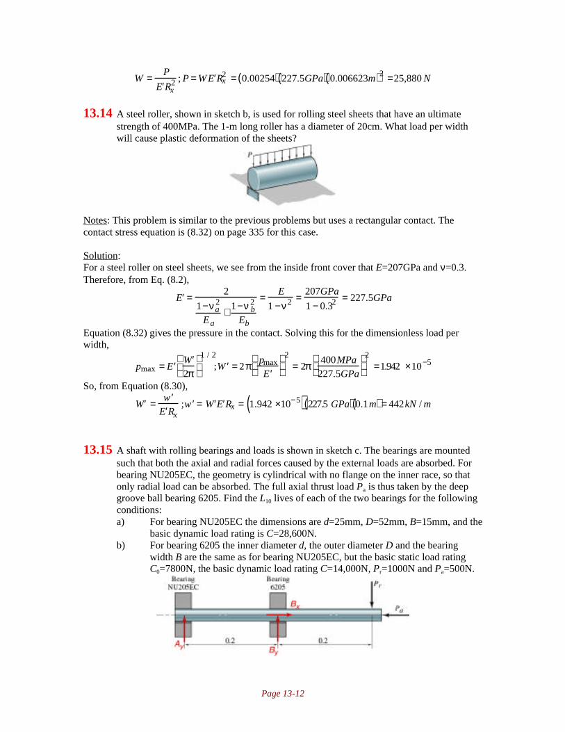
Page 13-12
W = P
′ E Rx2 ; P = W ′ E Rx
2 = 0.00254( ) 227.5GPa( ) 0.006623m( )2 =25,880 N
13.14 A steel roller, shown in sketch b, is used for rolling steel sheets that have an ultimatestrength of 400MPa. The 1-m long roller has a diameter of 20cm. What load per widthwill cause plastic deformation of the sheets?
Notes: This problem is similar to the previous problems but uses a rectangular contact. Thecontact stress equation is (8.32) on page 335 for this case.
Solution:For a steel roller on steel sheets, we see from the inside front cover that E=207GPa and ν=0.3.Therefore, from Eq. (8.2),
′ E = 2
1−νa2
Ea+ 1−ν b
2
Eb
= E
1 −ν2 = 207GPa
1 − 0.32 = 227.5GPa
Equation (8.32) gives the pressure in the contact. Solving this for the dimensionless load perwidth,
pmax = ′ E ′ W
2π
1 / 2
; ′ W = 2π pmax
′ E
2
= 2π 400MPa227.5GPa
2
=1.942 ×10⁻⁵
So, from Equation (8.30),
′ W = ′ w ′ E Rx
; ′ w = ′ W ′ E Rx = 1.942 ×10⁻⁵( ) 227.5 GPa( ) 0.1m( ) = 442kN / m
13.15 A shaft with rolling bearings and loads is shown in sketch c. The bearings are mountedsuch that both the axial and radial forces caused by the external loads are absorbed. Forbearing NU205EC, the geometry is cylindrical with no flange on the inner race, so thatonly radial load can be absorbed. The full axial thrust load Pa is thus taken by the deepgroove ball bearing 6205. Find the L10 lives of each of the two bearings for the followingconditions:a) For bearing NU205EC the dimensions are d=25mm, D=52mm, B=15mm, and the
basic dynamic load rating is C=28,600N.b) For bearing 6205 the inner diameter d, the outer diameter D and the bearing
width B are the same as for bearing NU205EC, but the basic static load ratingC0=7800N, the basic dynamic load rating C=14,000N, Pr=1000N and Pa=500N.

Page 13-13
Notes: The problem requires use of Equation (13.84) to find the L10 lives, as well as the capacityformulas for ball bearings given by Equation (13.84), (13.86) and Table 13.9.
Solution:The reactions have been sketched in the figure in red, noting that bearing NU205EC can only takeradial loads. From equilibrium in the x-direction, Bx=Pa=500N. From moment equilibrium,
By(0.2m)-Pr(0.4m)=0;By=2Pr=2(1000N)=2000N.From force equilibrium in the y-direction,
Ay+By-Pr=0;Ay=Pr-By=-1000NThe lives of the bearings are calculated using Equation (13.84). For the NU205EC
bearing, noting that mk=10/3 for a rectangular contact,
˜ L = C P
m k
= 28,600 N1000N
1 0 / 3
= 71,500 ×106rev
For the 6205 bearing, we have to calculate an equivalent load from Equation (13.86), but we firstneed the factors X and Y from Table 13.9 on page 592. Note that Pa/C0=500/7800=0.064, so fromTable 13.9 we use the row for the deep-groove ball bearing with e=0.27, which is close enough togive good results. Note that in this case Pa/Pr=500N/2000N=0.25, which is less then e, so we readX=1 and Y=0. Therefore, from Equation (13.86),
P=XPr+YPa=(1)(2000N)+0(500N)=2000NThe life is obtained from Equation (13.84) with mk=3 for an elliptical contact.
˜ L = C P
m k
= 14,000 N2000N
3
= 343×106 rev
13.16 Given the shaft and bearings in Problem 13.15 but with the bearing positions shifted sothe 6205 deep-groove ball bearing is in the left end of the shaft and bearing NU205EC isin the middle, find the L10 lives for the two bearings in their new positions.
Notes: This is very similar to Problem 13.15 and the same approach is used.
Solution:The immediate difference is that for the NU205EC bearing, the radial load is now 2000N, and theradial load for the 6205 bearing is now 1000N (it still carries the 500N axial force). Therefore, forthe NU205EC bearing, from Equation (13.84),
˜ L = C P
m k
= 28,600 N2000N
1 0 / 3
= 7098 ×106 rev
Just as in Problem 13.15, Pa/C0=0.064, so we say that e is around 0.27. Now Pa/Pr=0.5, which isgreater than e, so from Table 13.9 we see that X=0.56 and Y=1.6. Therefore the effective load is
P=XPr+YPa=(0.56)(1000N)+1.6(500N)=1360NTherefore, Equation (13.84) yields
˜ L = C P
m k
= 14,000 N1360N
3
=1091 ×106rev
This is the arrangement which gives a longer life.
13.17 A bearing arrangement for a shaft in a gearbox is shown in sketch d. Bearing A is acylindrical roller bearing (NU202EC) C=12,500N. Bearing B is a deep groove ball

Page 13-14
bearing (6309) Find which bearing is likely to fail first and what the L10 is for thatbearing. Length dimensions are in millimeters.
Notes: This is similar to problems 13.15 and 13.16, and the same equations and approach areused.
Solution:The reactions have been placed on the sketch in red. Note that the cylindrical bearing cannotsupport an axial load, so this has been taken fully by the deep groove bearing. From equilibriumin the x-direction,
1000N+Bx-2500cos30°=0; Bx=1165NFrom moment equilibrium about point A,
(2000N)(15mm)+(4000N)(30mm)-By(60mm)+(2500Nsin30°)(90)=0;By=4375NFrom equilibrium in the y-direction,
2000N+Ay-4000+By-2500sin30°=0; Ay=-1125NTherefore, for bearing A, the L10 is from Equation (13.84),
˜ L = C P
m k
= 12,500 N1125N
1 0 / 3
= 3061×106 rev
For bearing B, Pa/C0=1165/31500=0.037. From Table 13.9 on page 592, we see that e is nearly0.24. Since Pa/Pr=1165/4375=0.26>e, we read from Table 13.9 that X=0.56 and Y=1.8. Therefore,the effective load is
P = XPr + YPa = 0.56( ) 4375N( ) +1.8 1165N( )= 4547NSo that Equation (13.84) gives
˜ L = C P
m k
= 52700N4547N
3
=1556 × 106rev
13.18 The two bearings in Problem 13.17 have the same composite surface roughness of the
inner race, rolling element contact, (Rqa2+Rqb
2)
0.5=0.10µm. For bearing NU202EC the
outer radius of the inner race is 9.65 mm, the roller diameter is 5.7 mm, and inner radiusof the outer race is 15.35 mm. For bearing 6309 the ball diameter is 17mm, the outerradius of the inner race is 27.4 mm, and the inner radius of the outer race is 44.4 mm. Thelubricant used has the absolute viscosity η0=0.1Ns/m
2 and the pressure viscosity
coefficient ξ=2 x 10⁻⁸ m
2/N. The bearing rotational speed is 1500 rpm. The cylindrical
roller bearing has 13 rollers and the ball bearing has 10 balls. The ball bearing is made ofAISI 440C (E=200GPa), and the roller bearing is made of AISI 52100 (E=207GPa). Bothmaterials have ν=0.3. Find the adjusted bearing lives L10,adj for the two bearings when theellipticity ratios are 10 and ∞, respectively.

Page 13-15
Notes: This problem is similar to problems 13.10 through 13.13, but the adjusted L10 life isobtained from the film parameter using Figure 13.24 on page 594.
Solution:I. Roller BearingRx is obtained from Equation (8.17)
1Rx
= 1rax
+ 1rbx
= 19.65mm
+ 15 . 7 / 2mm
; Rx = 2.20mm
Also, Ry=∞ because this is a line contact. The velocity of the inner ring is given by
vr = rω = 9.65mm( ) 1500rpm( ) 2πrad / rev60sec /min
= 1.516m / s
The radius of the cage isrc = r
i+ d / 2= 9.65mm + 5.7mm / 2=12.5mm
The cage velocity is vc=vr/2=0.758m/s. Therefore, the angular velocity of the cage is
ωc = vc
rc= 0.758m / s
0.0125m= 60.64 rad / s
The entrainment velocity is then
u = 1500rpm( ) 2πrad / rev60s / m i n
− 60.64
0.00965 m( ) =0.931m / s
Therefore the dimensionless velocity parameter, calculated from Equation (13.70), is
U = η0u′ E Rx
=0.1Ns / m2( ) 0.931m / s( )227.5GPa( ) 0.0022m( ) = 1.86 ×10⁻¹⁰
The dimensionless materials parameter is from Equation (13.71),G=ξE’=(2x10
-8m
2/N)(227.5GPa)=4550
From Equation (13.49),
wz =n wz( )max
4; wz( )max = 4wz
n= 4 1 1 2 5N( )
13= 346N
Therefore, the load parameter is from Equation (13.69),
W = P
′ E Rx2 = 346N
227.5GPa( ) 0.0022m( )2 = 3.151×10⁻⁴
Note that ke=∞. Therefore, from Equation (13.72),
Hmin = hmin
Rx= hmin
0.0022m= 3.63U0.68G0.49W −0.073 1− e−0.68ke( )
= 3.63 1.86 × 10⁻¹⁰( )0.684550( )0.49 3.151 × 10⁻⁴( )−0.073
1− e−∞( ) = 9.800 ×10⁻⁵
Therefore hmin=0.216µm. The film thickness parameter is then Λ=0.216/0.10=2.16, and fromFigure 13.24, The L10 life is 1.3 times the rated L10 life.II. Ball BearingRx is given by
1Rx
= 1rax
+ 1rbx
= 11 7 / 2mm
+ 127.4mm
;Rx = 6.49mm
As above, the velocity of the inner ring is given by
vr = rω = 0.0274m( ) 1500rpm( ) 2πrad / rev60sec /min
= 2.152m / s
The radius of the cage isrc = r
i+ d / 2= 27.4mm +17mm /2 = 35.9mm

Page 13-16
The cage velocity is vc=vr/2=2.152m/s. Therefore, the angular velocity of the cage is
ωc = vc
rc= 2.152m / s
0.0359m= 59.94rad / s
The entrainment velocity is then
u = 1500rpm( ) 2πrad / rev60s / m i n
− 59.94
0.0274m( ) = 2.66m / s
Therefore the dimensionless velocity parameter, calculated from Equation (13.70), is
U = η0u′ E Rx
=0.1Ns / m2( ) 2.66m / s( )220GPa( ) 0.00649m( ) =1.863 ×10⁻¹⁰
The dimensionless materials parameter is from Equation (13.71),G=ξE’=(2x10
-8m
2/N)(220GPa)=4400
From Equation (13.50),
wz =n wz( )max
5; wz( )max = 5wz
n= 5 3287N( )
10=1643N
Therefore, the load parameter is from Equation (13.69),
W = P
′ E Rx2 = 1643N
220GPa( ) 0.00649m( )2 =1.774 ×10⁻⁴
Note that ke=10. Therefore, from Equation (13.72),
Hmin = hmin
Rx= hmin
0.0022m= 3.63U0.68G0.49W −0.073 1− e −0.68ke( )
= 3.63 1.86 × 10⁻¹⁰( )0.684400( )0.49 1.774 × 10⁻⁴( )−0.073
1− e−6.8( ) = 1.005 × 10⁻⁴
Therefore hmin=0.652µm. The film thickness parameter is then Λ=0.652/0.10=6.52, and fromFigure 13.24, The L10 life is 2.3 times the rated L10 life.
13.19 Given the shaft arrangement in Figure 11.3 with the applied forces indicated, bearing B isa cylindrical roller bearing of type NU304EC with C=30,800N, and bearing A is a deep-groove ball bearing of type 6404 (C=30,700, C0=15,000N). Find the L10 life for eachbearing and judge if they are strong enough to be used at 1500rpm for 20 years.
Notes: This problem is similar to the previous problems, where an L10 life will be calculated fromEquation (13.84). Here the calculated life will be compared to the number of cycles expected inservice.
Solution:From Figure 11.3, the reaction components at bearing A are 475N and 150N, and at B thecomponents are 650N and 475N. Therefore the radial forces on A and B are:
RA = 475N( )2 + 150N( )2 = 498N
RB = 475N( )2 + 650N( )2 = 805NFor the NU304EC bearing, Equation (13.84) gives
˜ L = C P
m k
= 30,800 N805N
1 0 / 3
= 1.887×10⁵ million rev.
For the 6404 bearing, Equation (13.84) gives
Page 13-17
˜ L = C P
m k
= 30,700 N498N
3
= 2.343× 10⁵ million rev.
If the bearing is run at 1500rpm for 20 years, the number of revolutions the bearings experience isgiven by:
L = 1500rev / m i n( ) 60min /hr( ) 24hr / day( ) 365day / year( ) 20years( ) =1.577 ×10⁴million rev
13.20 Given the shaft arrangement in Problem 13.19 but with the belt drive at D changed to aworm gear giving the same radial force but also an additional axial force of 800Ndirected from D to A, find the L10 lives of the bearings and judge if they are strong enoughto last 20 years at 1500rpm.
Notes: This problem is very similar to Problem 13.19. Note that the cylindrical bearing cannotsupport the thrust force; this must be taken by the deep groove ball bearing.
Solution:The cylindrical bearing is unchanged, since the thrust force is taken by the deep groove bearing.The ball bearing sees a radial load of 498N and an axial force of 800N. Therefore, sincePa/C0=800N/15000N=0.053, Table 13.9 on page 592 gives e=0.25. Note thatPa/Pr=800/498=1.61, which is larger than e, so we read from Table 13.9 that X=0.56 and Y=1.7.Therefore, the effective load is obtained from Equation (13.86) as
P = XPr + YPa = 0.56( ) 498N( ) +1.7 800 N( ) =1639NSo that Equation (13.84) gives
˜ L = C P
m k
= 30,700 N1639N
3
= 6572 million rev
The life is, as in Problem 13.19,
L = 1500rev / m i n( ) 60min /hr( ) 24hr / day( ) 365day / year( ) 20years( ) =1.577 ×10⁴million revso the bearing is still sufficient for the application, but the bearing life is less than the rated life ofthe application.
13.21 A flywheel has deep groove ball bearings located close to the rotating disk. The diskmass is 50kg, and it is mounted out of balance, so that the center of mass is situated at aradius 1 mm from the bearing centerline. The shaft mass is neglected. The bearings aretwo 6305 deep groove ball bearings with C=22,500N. Find the nominal bearing L10 inhours for each bearing ata) 500 rpmb) 2500 rpmc) 12,500 rpm
Notes: For this problem, the force is assumed to be applied equally to the two bearings, and issimply the product of the flywheel’s acceleration and its mass. The acceleration is that due togravity and that due to the eccentricity of the flywheel, given by rω2
/2.
Solution:Assuming the force of the flywheel is shared between the two bearings, the force on the bearingsis:

Page 13-18
F = m2
a = m2
g+ rω 2( )At 500 rpm=52.36rad/s, the bearing load is
F = m2
a = m2
g+ rω 2( ) =50kg( )
29.81m / s2 + 0.001m( ) 52.36rad / s( )2( ) = 314N
The L10 life is given by Equation (13.84) as
˜ L = C P
m k
= 22500N314N
3
= 3.68×10⁵ million rev
At 500 rpm, this is 12.3 million hours.At 2500 rpm=262rad/s, the bearing load is
F = m2
a = m2
g+ rω 2( ) =50kg( )
29.81m / s2 + 0.001m( ) 262rad / s( )2( ) = 1961N
The L10 life is given by Equation (13.84) as
˜ L = C P
m k
= 22500N1961N
3
= 1510 million rev
At 2500 rpm, this is 10,000 hours.At 12,500 rpm=1309rad/s, the bearing load is
F = m2
a = m2
g+ rω 2( ) =50kg( )
29.81m / s2 + 0.001m( ) 1309rad / s( )2( ) = 43kN
The L10 life is given by Equation (13.84) as
˜ L = C P
m k
= 22500N43000 N
3
= 0.142 million rev
At 12500 rpm, this is 0.19 hours (11 minutes).
13.22 A ball bearing manufacturer wants to make sure that its bearings get long service lives ondifferent components. Extra polishing operation can be applied toa) the ring surfacesb) the ball surfacesc) all contact surfaces
The polishing decreases the roughness by one-half the original roughness, which for the races is0.08 µm and for the balls is 0.04 µm. Find how much the Λ value changes when either a,b, or c is polished.
Notes: This problem requires the use of the film parameter, given by Equation (8.3) for itssolution. The change cannot be calculated absolutely, it can only be compared to the original casewith the information given.
Solution:From Equation (8.8), the film parameter applied to the original surface is
Λ0 = hmin
0.08µm( )2 + 0.04µm( )2= 11.18/ µm( )hmin
If the ring surface is polished to 0.04 µm, and the ball surface roughness remains 0.04µm, thefilm parameter is
Λa = hmin
0.04µm( )2 + 0.04µm( )2= 17.68/ µm( )hmin

Page 13-19
which is 1.581 times the original case. If the ball surface is polished to 0.02µm and the ring isunchanged, then the film parameter is:
Λb = hmin
0.08µm( )2 + 0.02µm( )2= 12.13/ µm( )hmin
This is 1.085 times the original film parameter. If both the ball and the ring are polished, then thefilm parameter becomes:
Λc = hmin
0.04µm( )2 + 0.02 µm( )2= 22 .36 /µm( )hmin
Which is 2 times the original film parameter. It is best to polish the roughest surface, and it is notas advantageous to further polish already smooth surfaces.
13.23 The shaft shown in sketch e transfers power between the two pulleys. The tension on theslack side (right pulley) is 30% of that on the tight side. The shaft rotates at 900 rpm and issupported uniformly by a radial ball bearing at points O and B. Select a pair of radial ballbearings with 99% reliability and 30,000hr of life. All length dimensions are in millimeters.
Notes: Obtaining the forces on the bearings is the most time consuming portion of this problem.The life at 99% reliability is obtained from Figure 13.23 compared to the L10. Otherwise theproblem is similar to the previous few problems.
Solution:The reactions have been added to the sketch in red. Note that the bearings cannot support atorque. Therefore, the tension in the 600 mm diameter pulley can be determined from torqueequilibrium:
(900N)(250mm)-(100N)(250mm)-T(300mm)+0.3T(300mm)=0; T=952.4NNow consider the xy plane. Taking moments about point O,
(1000N)(500mm)+By(900mm)=0;By=-555NThe force is negative because it acts downwards. Summing forces in the y-direction,
ΣFy=0=Oy+1000N-555N;Oy=-444NNow consider the xz plane. Taking moments about point O,
Bz(900mm)+(952.4+0.3(952.4))(1100mm)=0;Bz=-1513NSumming forces in the z-direction,
ΣFz=0=Oz-1513N+1.3(952.4N);Oz=275N
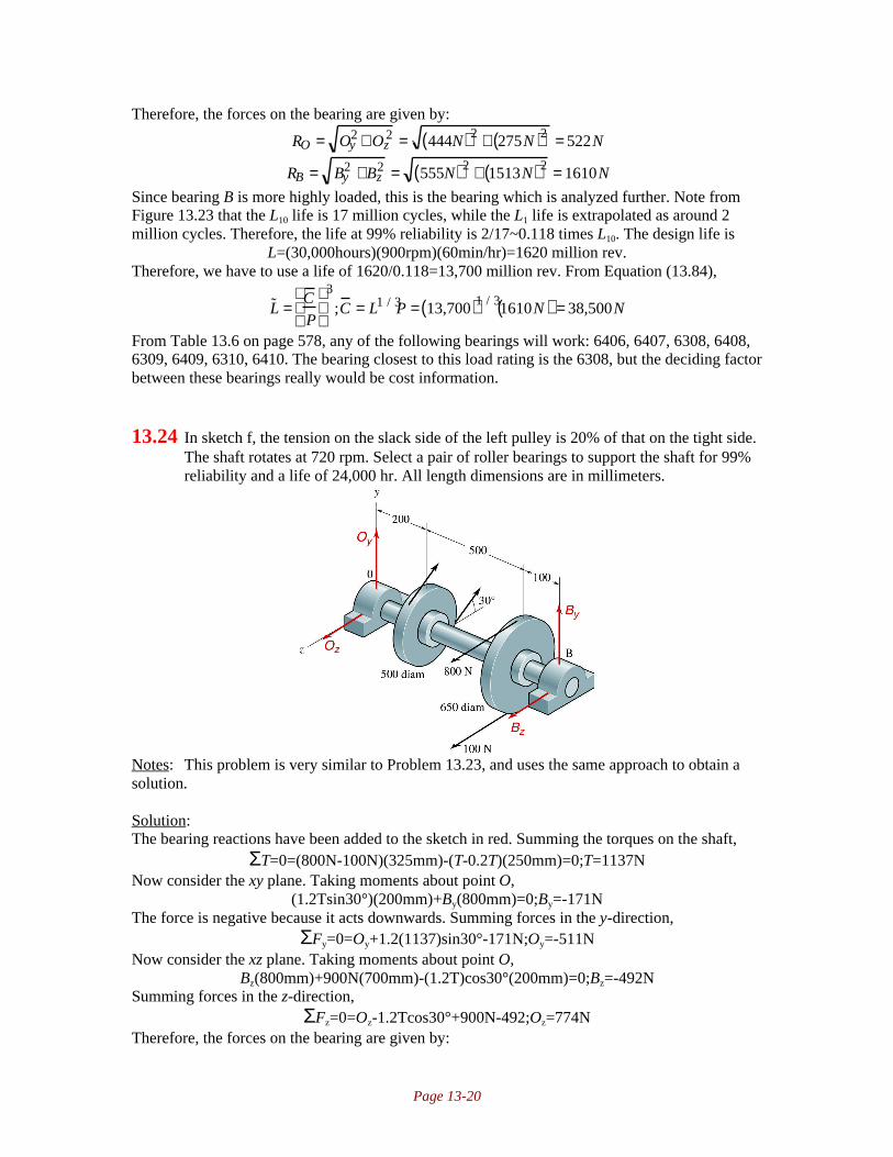
Page 13-20
Therefore, the forces on the bearing are given by:
RO = Oy2 + Oz
2 = 444N( )2 + 275N( )2 = 522N
RB = By2 +Bz
2 = 555N( )2 + 1513N( )2 = 1610N
Since bearing B is more highly loaded, this is the bearing which is analyzed further. Note fromFigure 13.23 that the L10 life is 17 million cycles, while the L1 life is extrapolated as around 2million cycles. Therefore, the life at 99% reliability is 2/17~0.118 times L10. The design life is
L=(30,000hours)(900rpm)(60min/hr)=1620 million rev.Therefore, we have to use a life of 1620/0.118=13,700 million rev. From Equation (13.84),
˜ L = C P
3
;C = L1 / 3P = 13,700( )1 / 31610N( ) = 38,500N
From Table 13.6 on page 578, any of the following bearings will work: 6406, 6407, 6308, 6408,6309, 6409, 6310, 6410. The bearing closest to this load rating is the 6308, but the deciding factorbetween these bearings really would be cost information.
13.24 In sketch f, the tension on the slack side of the left pulley is 20% of that on the tight side.The shaft rotates at 720 rpm. Select a pair of roller bearings to support the shaft for 99%reliability and a life of 24,000 hr. All length dimensions are in millimeters.
Notes: This problem is very similar to Problem 13.23, and uses the same approach to obtain asolution.
Solution:The bearing reactions have been added to the sketch in red. Summing the torques on the shaft,
ΣT=0=(800N-100N)(325mm)-(T-0.2T)(250mm)=0;T=1137NNow consider the xy plane. Taking moments about point O,
(1.2Tsin30°)(200mm)+By(800mm)=0;By=-171NThe force is negative because it acts downwards. Summing forces in the y-direction,
ΣFy=0=Oy+1.2(1137)sin30°-171N;Oy=-511NNow consider the xz plane. Taking moments about point O,
Bz(800mm)+900N(700mm)-(1.2T)cos30°(200mm)=0;Bz=-492NSumming forces in the z-direction,
ΣFz=0=Oz-1.2Tcos30°+900N-492;Oz=774NTherefore, the forces on the bearing are given by:

Page 13-21
RO = Oy2 + Oz
2 = 511N( )2 + 774 N( )2 = 927N
RB = By2 +Bz
2 = 171N( )2 + 492 N( )2 = 521N
Therefore the bearing at O is critical. Note from Figure 13.23 that the L10 life is 17 million cycles,while the L1 life is extrapolated as around 2 millions cycles. Therefore, the life at 99% reliabilityis 2/17~0.118 times L10. The design life is
L=(24,000hours)(720rpm)(60min/hr)=1037 million rev.Therefore, we have to use a life of 1037/0.118=8,786rev. From Equation (13.84),
˜ L = C P
1 0 / 3
;C = L0.3P = 8,786( )0.3 927 N( ) =14,132 N
From Table 13.7 on page 581, any of the bearings on this table will suffice.
13.25 In sketch g the shaft rotates at 1100 rpm and transfers power with light shock from a 600mm diameter pulley to a 300mm diameter sprocket. Select a radial ball bearing forsupport at O and a roller bearing for support at A. The bearings should have a life of24,000 hr at 95% reliability. All length dimensions are in millimeters.
Notes: This is similar to Problem 13.24, and uses the same approach. We are selecting bearingswith no regard to the resulting stress concentration associated with the fillet needed to bemachined into the shaft to allow for bearing mounting. In practice, the shaft shoulder oftendetermines the bearing size, and therefore results in very large safety factors.
Solution:The bearing reactions have been added to the sketch in red. Summing the torques on the shaft,
ΣT=0=(400N-60N)(300mm)-(P)(150mm)=0;P=680NNow consider the xy plane. Taking moments about point O,
-(460sin20°)(400mm)+Ay(600mm)=0;Ay=105NSumming forces in the y-direction,
ΣFy=0=Oy-460Nsin20°+105N;Oy=52.3NNow consider the xz plane. Taking moments about point O,
Az(600mm)-680N(800mm)+(460N)cos20°(400mm)=0;Az=618.5NSumming forces in the z-direction,
ΣFz=0=Oz+460Ncos20°+618.5N-680N;Oz=-371NTherefore, the forces on the bearing are given by:
RO = Oy2 + Oz
2 = 52.3N( )2 + 371N( )2 = 375N
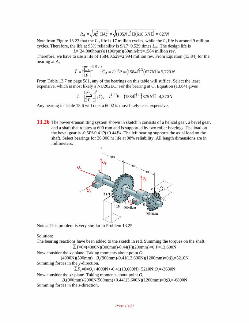
Page 13-22
RA = Ay2 + Az
2 = 105N( )2 + 618.5N( )2 = 627N
Note from Figure 13.23 that the L10 life is 17 million cycles, while the L5 life is around 9 millioncycles. Therefore, the life at 95% reliability is 9/17~0.529 times L10. The design life is
L=(24,000hours)(1100rpm)(60min/hr)=1584 million rev.Therefore, we have to use a life of 1584/0.529=2,994 million rev. From Equation (13.84) for thebearing at A,
˜ L = C AP
1 0 / 3
;C A = L0.3P = 1584( )0.3 627N( ) = 5,720 N
From Table 13.7 on page 581, any of the bearings on this table will suffice. Select the leastexpensive, which is most likely a NU202EC. For the bearing at O, Equation (13.84) gives
˜ L = C AP
3
;C A = L1 / 3P = 1584( )1 / 3375N( ) = 4,370N
Any bearing in Table 13.6 will due; a 6002 is most likely least expensive.
13.26 The power-transmitting system shown in sketch h consists of a helical gear, a bevel gear,and a shaft that rotates at 600 rpm and is supported by two roller bearings. The load onthe bevel gear is -0.5Pi-0.41Pj+0.44Pk. The left bearing supports the axial load on theshaft. Select bearings for 36,000 hr life at 98% reliability. All length dimensions are inmillimeters.
Notes: This problem is very similar to Problem 13.25.
Solution:The bearing reactions have been added to the sketch in red. Summing the torques on the shaft,
ΣT=0=(4000N)(300mm)-0.44(P)(200mm)=0;P=13,600NNow consider the xy plane. Taking moments about point O,
(4000N)(500mm) +By(900mm)-0.41(13,600N)(1200mm)=0;By=5210NSumming forces in the y-direction,
ΣFy=0=Oy+4000N+-0.41(13,600N)+5210N;Oy=-3630NNow consider the xz plane. Taking moments about point O,
Bz(900mm)-2000N(500mm)+0.44(13,600N)(1200mm)=0;Bz=-6890NSumming forces in the z-direction,

Page 13-23
ΣFz=0=Oz-2000N-6890N+0.44(13,600N);Oz=2890NTherefore, the forces on the bearing are given by:
RO = Oy2 + Oz
2 = 3630N( )2 + 2890N( )2 = 4640N
RB = By2 +Bz
2 = 5210N( )2 + 6890N( )2 = 8640N
Note from Figure 13.23 that the L10 life is 17 million cycles, while the L2 life is around 3.9 millioncycles. Therefore, the life at 98% reliability is 3.9/17~0.230 times L10. The design life is
L=(36,000hours)(600rpm)(60min/hr)=1296 million rev.Therefore, we have to use a life of 1296/0.23=5437 million rev. From Equation (13.84) for thebearing at B,
˜ L = C BP
1 0 / 3
;C B = L0.3P = 5437( )0.3 8640N( ) = 115,300N
From Table 13.7 on page 580, none of the bearings on this table will suffice. Additional bearingsare listed on the CD, from which a NU410EC is selected. For the bearing at O, Equation (13.84)gives
˜ L =C OP
1 0 / 3
;C O = L0.3P = 5437( )0.3 4640N( ) = 61,252N
Note that there is a thrust load, so one of the bearings should be a thrust bearing or a taperedroller bearing, probably the one at O since the radial load is smaller. However, if there is aanother method of supporting the axial load, with a hydrodynamic thrust bearing for example,then we can use two roller bearings as prescribed in the problem statement. For the bearing at B,the load rating is higher than any bearing on the chart. An NU410EC can be used (as taken fromthe data on the CD) or else a pair of NU307EC bearings can be used. For the bearing at O, anNU307EC is probably the best choice based on cost, but the shaft diameter may suggest adifferent bearing.
13.27 A cylindrical roller bearing is used to support an 8kN load for 1200 hr at 600rpm.Calculate the load-carrying capacity of this bearing for 95% reliability. What size bearingwould you recommend?
Notes: This is very straightforward, and uses the same approach as the previous few problemsbut without the statics.
Solution:The life is
L10=(1200hr)(600rpm)(60min/hr)=43.2 million rev.Note from Figure 13.23 that the L10 life is 17 million cycles, while the L5 life is around 9 millioncycles. Therefore, the life at 95% reliability is 9/17~0.529 times L10. The design life is 43.2/0.529=81.7 million rev. Therefore, from Equation (13.84)
˜ L = C P
1 0 / 3
;C = L0.3P = 81.7( )0.3 8000N( ) = 30,000 N
From Table 13.7, a NU304EC bearing is sufficient for this application.

Page 13-24
13.28 A deep-groove ball bearing is used to support a 6kN load for 1000 hr at 1200 rpm. For99% reliability what should be the load-carrying capacity of the bearing? What sizebearing should be chosen?
Notes: This problem is the same as Problem 13.27, but with a ball bearing so that mk=3 instead of10/3 in Equation (13.84).
Solution:The life is
L10=(1200hr)(1000rpm)(60min/hr)=72 million rev.Note from Figure 13.23 that the L10 life is 17 million cycles, while the L1 life is extrapolated asaround 2 million cycles. Therefore, the life at 99% reliability is 2/17~0.118 times L10. The designlife is 72/0.118 =610 million rev. Therefore, from Equation (13.84)
˜ L = C P
3
;C = L1 / 3P = 610( )1 / 36000N( ) =50 ,900N
From Table 13.6, a 6407 or larger bearing is sufficient for this application.
Page 14-1
14 • Gears
14.1 For gear transmissions there is a direct proportionality between the local sliding speedexperienced by the contacting surfaces and the power loss. For a normal spur or helicalgear the mean sliding speed is typically 20% of the load transmission speed. Thecoefficient of friction in lubricated gears is typically between 0.05 and 0.1. This leads to apower loss of 1 to 2% and a power efficiency of 99 to 98%. For a hypoid gear in the rearaxle of a car the sliding speed can be 60% of the load transmission speed, and for a wormgear it can be 1200%. Estimate the power efficiencies for a hypoid gear and a worm gear.
Notes: This problem uses the first law, namely that the power input equals the power output plusfrictional losses, and that the efficiency is the ratio of power output to the power input.
Solution:From the first law of thermodynamics, the power input is the outpur power plus the power loss, orhpi=hpµ+hpo. Since the power loss is proportional to the sliding speed, we can write:
hpi = AµNvs + Nvo
The efficiency is defined as the output power divided by the input power. We can use the data forthe spur or helical gear to define the constant A:
e = 99 − 98% = Nvo
AµNvs + Nvo= Nvo
A 0.05 − 0.1( ) 0.2( )Nvo + Nvo;
A = 1
0.05 − 0.1( ) 0.2( ) + 1( ) 0.99 − 0.98( )= 1.0001 − 0.9996
So we can take A as 1. For the hypoid gear the efficency is therefore,
e =Nvo
0.05 − 0.1( ) 0.60( ) + 1( )Nvo= 97% − 94%
while for the worm gear,
e =Nvo
0.05 − 0.1( ) 12( ) + 1( )Nvo= 62.5% − 45.5%
14.2 A pinion has a pressure angle of 20°, a module of 3mm, and 22 teeth. It is meshed with agear having 32 teeth. The center distance between the shafts is 81mm. Determine the gearratio and the diametral pitch.
Notes: The equations needed to solve this problem are Equations (14.3) and (14.9)
Solution:The diametral pitch is, from Equation (14.9):
m =1
pd; pd =
1
m=
1
3mm= 0.333mm−1
The gear ratio is obtained from Equation (14.3):
gr =Ng
N p=
32
22= 1.45
14.3 A gearbox has permanent shaft positions due to the bearing positions, but the gear ratiocan be changed by changing the gear wheels. To achieve similar power transmission

Page 14-2
ability for different gear ratios, a manufacturer chooses to have the same module for twodifferent gear boxes. One of the gear boxes has a pinion with 22 teeth, a gear with 68teeth, and a center distance of 225mm. How large is the gear module and which gearratios are possible for a pinion with 22 or more teeth for the same module?
Notes: The center distance of 225 mm is constant; Equations (14.3), (14.4), (14.6), and (14.9) areused in this problem.
Solution:If the shaft positions are constant, then the center distance of 225 mm is constant. From Equations(14.4) and (14.6) we can calculate the diametral pitch for the specified gear box as:
cd =pc
2πN p + Ng( ) =
1
2 pdNp + Ng( ); pd =
N p + Ng( )2cd
=22 + 68
2 225mm( )= 0.2mm−1
From Equation (14.9) the module is m=1/pd=5mm.Note from Equation (14.4) that if the center distance is constant, then the total number of
teeth in the gear and pinion is constant and equals 90. The gear ratio is given by Equation (14.3)as
gr =Ng
N p=
90 − N p
N p
The pinion, from the definition on page 615, is the smaller wheel. Therefore, Np varies from 22to 45 teeth (note: you can't have a gear with a half-tooth, so Np must be an integer). The gearratios possible are 3.091, 2.913, 2.75, 2.6, 2.462, 2.333, 2.214, 2.103, 2.000, 1.903, 1.813, 1.727,1.647, 1.571, 1.500, 1.432, 1.368, 1.308, 1.250, 1.195, 1.143, 1.093, 1.045, and 1.000.
14.4 The blank for a normal gear with 20 teeth was made too large during manufacturing.Therefore, the addendum for the gear teeth was moved outward, and the tooth thicknessat the tops of the teeth was decreased. The module for the rack was 2mm. Find how largethe maximum gear outside radius can be when the tool flank angle is 20° to avoid zerothickness at the tops.
Solution:The maximum outside circle radius of the gear is the radius that gives the tooth tip thicknessequal to zero. Normal gears have the tooth thickness on the rolling circle of πm/2 and the rollingcircle radius of mN/2. The tooth thickness at the base circle is
sb
mN cos20°=
πN
+ t a n 2 0° −20π180
If the tip radius of the gear is ro when the thickness is zero,sb
m= N tan20° −
20π180
+ π
c o s 2 0° =
2
mro sinα − rbα( )=
2rbm
tanα − α( ) = N sinα − α cosα( )
for a gear with 20 teeth,
sinα − α cosα = tan20° −20π180
+π20
c o s 2 0°;α = 46°
The outside radius is
ro =rb
c o s 4 6°=
mN / 2( ) cos20°cos46°
=2 20( )cos20°
2 c o s 4 6°= 27.05mm
So the maximum outside radius of the gear is 27mm.

Page 14-3
14.5 The inlet and outlet speeds for a reduction gear train are 2000 and 320 rpm, respectively.The pressure angle is designed to be 25°. The gears have a 5 mm module and their centerdistance is 435mm.a) Determine the number of teeth for both gears, the angular pitch, and the radii of
the base, addendum and dedendum circles.b) Find the maximum allowable change in center distance.
Notes: This problem is fairly straightforward, merely requiring direct evaluation of the equationsin section 4.3.
Solution:Equation (14.1) gives
dp+dg=2cd=2(435mm)=870mmAlso, from Equation (14.18),
dg =ωp
ωgdp =
2000
320
d p = 6.25dp
Substituting, dp=120mm, dg=750mm. The number of teeth in the pinion and gear are given byEquation (14.7):
m =dg
Ng; Ng =
dg
m= 750mm
5mm=150T
Np =d p
m= 120mm
5mm= 24T
The circular pitch is, from Equation (14.8):pc=πm=5π=15.7mm
The base circle radii are, from Equation (14.16):
rbp =dp cosφ
2= 120mm cos25°
2= 54.38mm
rbg =dg cosφ
2= 750mm cos25°
2= 339.9mm
Then by using the relations in Table 14.2 and Equations (14.11) through (14.14):
rap =dop
2=
dp
2+ m = 120
2+ 5 = 65mm
rag =dog
2=
dg
2+ m = 750
2+ 5= 380mm
rrp =drp
2=
dp
2− 1.25m = 120
2− 1.25(5) = 53.75
rrg =drg
2=
dg
2− 1.25m = 750
2− 1.25(5) = 368.75mm
The maximum allowable change in center distance is394.25
cos25.9°− 435 = 3.27mm
14.6 The base circle radii of a gear pair are 100 and 260 mm, respectively. Their module is8mm and the pressure angle is 20°. Mounting inaccuracy has caused a 5mm change in

Page 14-4
center distance. Calculate the change in the pitch radii, the center distance, and thepressure angle.
Notes: This problem introduces the equations in section 14.3.3. Equations (14.16), (14.18),(14.1), and (14.5) are used to solve this problem.
Solution:The radii and pressure angle for the gear and pinion are related by Equation (14.16):
rbp = rp cosφ ;rp =rbp
cosφ= 100mm
cos20°= 106.4mm
rbg = rg cosφ ;rg =rbg
cos φ= 260mm
cos20°= 276.7mm
The center distance is given by Equation (14.1). We use a prime symbol to indicate the as-manufactured case, so that we can write:
cd = rp + rg = 267.6mm +106.4mm = 383.1mm
The new center radius is five millimeters higher than this, or
cd′ = cd + 5mm = rp
′ +rg′ = 383.1mm + 5mm = 388.1mm
From equation (14.18),
dp′
dg′ =
N p
Ng=
rp
rg=
rp′
rg′ = 106.4mm
276.7mm= 0.3845
Or that rp’=0.3845rg
’. Substituting into the equation for center distance gives
rp′ + rg
′ = 0.3845rg′ + rg
′ = 388.1 mm;rg′ = 280.3mm
Therefore rp’=107.8mm. The changes in the pitch radii are ∆rg=280.3-276.7=3.61mm,
∆rp=107.8-106.4=1.4mm. The pressure angle is obtained from Equation (14.16) as
rbp = rp′ cos ′ φ ;φ = cos−1 rbp
rp′
= cos −1 100mm
107.8 mm
= 21.92°
14.7 A gear train has a 50.3 mm circular pitch and a 25° pressure angle. Design this gear trainfor the lowest volume occupied and the fewest teeth. Obtain the pitch diameters, thenumber of teeth, the speed ratio, the center distance, and the module of the gear train. Thegearbox housing has a diameter of 620mm.
Notes: This is an open ended problem in a number of ways. First of all, the number of teeth is setby the center distance. Also, the gears should not contact the gearbox housing, so a reasonableclearance has to be chosen. In this solution, we use Np=12 and a clearance between the gears andhousing of 6 mm. These are reasonable values, but are by no means representative of the onlysolution.
Solution:From Equation (14.8), the module is given by
pc=πm;m=pc/π=50.3mm/π=16.0mmIf the number of teeth in the pinion is 12, then the diameter of the pinion is then
dp=mNp=(16mm)(12)=192mmIf the clearance between the housing and the gears is c=6mm, the housing diameter is
dh=dp+dg+2m+2c; 620mm=192mm+dg+2(16mm)+2(6mm); dg=384mm

Page 14-5
Therefore, the number of teeth in the gear is Ng=dg/m=384/16=24. The gear ratio is from Equation(14.18),
gr =ωp
ωg=
Ng
Np=
24
12= 2
The center distance is, from Equation (14.1),cd=(dg+dp)/2=(384mm+192mm)/2=288mm
14.8 For the gears in Example 14.4 calculate the maximum sliding speed between thecontacting gear teeth, and give the position along the line of action where the maximumsliding speed occurs.
Notes: This is an advanced problem that requires good knowledge of Figure 14.11 to obtain thesliding velocity. Gear geometries are obtained in similar fashion to the previous problems. Thesliding speed is the difference in speed perpendicular to the line of action for the two gears. At thepitch point the sliding speed is zero. The sliding speed increases on both sides of the pitch pointand reaches local maxima at the far ends of the line of action (points a and b in Figure 14.11).Note that Example 14.4 gives the tangential velocity at the pitch point, which is different than thegoal in this problem.
Solution:In example 14.4, it is given that Np=20, Ng=38, φ=20°, pd=8 per inch and ωp=3600rpm =377rad/s,and it was calculated that dp=2.5in. From Equation (14.5) it can also be calculated that
dg=Ng/pd=38/8=4.75inTherefore the center distance, from Equation (14.1) is
cd=(dp+dg)/2=(2.5in+4.75in)/2=3.625inThe angular speed of the gear is obtained from Equation (14.18):
ωp
ωg=
Ng
N p;ωg =
N pωp
Ng=
20( ) 377rad / s( )38
=198.4rad / s
From Table 14.2 on page 623, it can be seen that the addendum is a=1/pd=(1/8)in=0.125in.Applying Equations (14.11) and (14.12) to the pinion and gear,
dop=dp+2a=2.5in+2(0.125in)=2.75in; rop=1.375indog=dg+2a=4.75in+2(0.125in)=5.00in; rog=2.50indbp=dp-2a=2.5in-2(0.125in)=2.25in; rbp=1.125indbg=dg-2a=4.75in-2(0.125in)=4.5in; rbg=2.25in
From Figure 14.11 we can obtain the following distances:La*b*=cdsinφ=(3.625in)sin20°=1.240inLa*c=rpsinφ=(1.25in)sin20°=0.4275in
Lcb*=rgsinφ=(4.75in/2)sin20°=0.8123in
Lac = rog2 − rbg
2 − rg sinφ = 2.50in( )2 − 2.25in( )2 − 4.75in / 2( )sin20° = 0.3142in
La*a=La*c-Lac=0.4275in-0.3142in=0.1033in
Lcb = rop2 − rbp
2 − rp sinφ = 1.375in( )2 − 1.125in( )2 − 1.25in( )s i n 2 0° = 0.2873 in
Lbb*=Lcb*-Lcb=0.8123-.2873=0.5252inLab*=La*b*-La*a=1.240in-0.1033in=1.1367inLa*b=La*b*-Lbb*=1.240in-0.5252in=0.7148in
Therefore, the sliding velocity at point a isvsa=Lab*ωg-La*aωp=(1.1367in)(198.4rad/s)-(0.1033in)(377rad/s)=186.6in/s

Page 14-6
Similarly, at b,vsb=La*bωp-Lb*bωg=(0.7150in)(377rad/s)-(0.525in)(198.4rad/s)=165.4in/s
The larger sliding velocity is at a and is 186.6in/s.
14.9 The pinion of the gear train for an endurance strength test machine (sketch a) has 5kW ofpower and rotates clockwise at 1200 rpm. The gears have a 12.57mm circular pitch and a20° pressure angle.a) Find the magnitude and direction of the output speed.b) Calculate the center distance between the input and output shafts.c) Draw free body diagrams of forces on gears 3 and 4.
Notes: This is a very straightforward problem, requiring manipulation of the Equations (14.1),(14.2), (14.5) (14.25), and (14.34)
Solution:The train ratio for this gear train is obtained by applying equation (14.25) twice:
Z52 = N2
N3
N4
N5= 30
504045
= 0.533
Therefore the output shaft is rotating at a speed of Z52Ni=0.533(1200rpm)=640rpm. Since we havean even number of externally meshing gears, the rotation is in the same direction as the input. Tocalculate the center distance from Equation (14.2), we need the gear diameters. We can do thisusing Equation (14.5) once we calculate the pitch diameters. The circular pitch is given as12.57mm. From Equation (14.2),
pc = πdN
=πdg
Ng;dg =
pcNg
π=
12.57mm( )Ng
π≈ 4mm( )Ng
Applying this equation for each gear gives d2=4(30)=120mm, d3=4(50)=200mm,d4=4(40)=160mm, and d5=4(45)=180mm. To calculate the center distance between the shafts,apply Equation (14.1) twice:
cd = cd( )23 + cd( )45 = d2 + d3
2+
d4 + d5
2= 120mm + 200mm
2+ 160mm + 180mm
2= 330mm
The free body diagrams of gears 3 and 4 are asfollows:

Page 14-7
We calculate the tangential forces by noting that power is the product of force and velocity(Equation 4.36), so that
hp = Wt3v3 = Wt3v2 ;Wt3 =hp
v2=
hp
r2ω2= 5000Nm / s
0.120 m / 2( ) 1200rev / m i n( ) 2πrad / rev
60sec /min
= 663.2N
Since the angular velocity of the output shaft was calculated earlier as 640rpm, we can apply thesame equation to obtain the tangential force on gear 4 as:
hp = Wt4v4 = Wt4v5 ;Wt4 =hp
v5=
hp
r5ω 5=
5000Nm / s
0.180m / 2( ) 640rev / min( ) 2πrad / rev60sec /min
= 828.9N
The normal forces are obtained from Equation (14.34) asWr=Wttanφ; Wr3=Wt3tanφ=(663.2N)tan20°=241.4N
Wr4=Wt4tanφ=(828.9N)tan20°=301.7N
14.10 A standard straight gear system consists of two gears with tooth numbers Ng=51 andNp=20. Pressure angle=20° and diametral pitch pd=5.08 per inch. Find the center distancecd and the contact ratio Cr.
Notes: This is similar to the previous problem, but introduces the contact ratio defined byequation (14.20). To determine the length of the line of action, the properties in Table 14.2 needto be determined.
Solution:To obtain the center distance, we use Equation (14.1), but first need to calculate the pinion andgear diameters. Note that from equation (14.6) the circular pitch is
pc=π/pd=π/(5.08in-1)=0.6184in.
The diameters of the pinion and gear are calculated from equation (14.2):
pc =πd p
Np;dp =
Nppc
π=
Np
pd= 20( )
5.08 in−1 = 3.94 in
pc =πdg
Ng;dg =
Ngpc
π=
Ng
pd= 51( )
5.08in−1 = 10.04in
The center distance is then calculated as (from Equation 14.1):
cd =dp + dg
2= 3.94in +10.04in
2= 6.99 in
To calculate the contact ratio, we need the length of the line of action (see Equation (14.19)). Todo so we need the base and outer radii. The outer radii (one-half the outer diameter) is obtained
from Equation (14.11):rop=rp+ap=(3.94in)/2+0.1969=2.17inrog=rg+ag=(10.04in)/2+0.1969=5.22in
From Figure 14.11, it can be seen that rb=rcosφ, so thatrbp=rpcosφ=(3.94in/2)cos20°=1.85inrbg=rgcosφ=(10.04in/2)cos20°=4.72in
From Equation (14.19), Lab is
Lab = rop2 − rbp
2 + rog2 − rbg
2 − cd sinφ = 0.973in

Page 14-8
Therefore, the contact ratio is given by Equation (14.20) as
Cr = Lab
pc cosφ= 0.973in
0.6184in( )cos20°= 1.67
14.11 Given a straight gear with diametral pitch pd=6.35 per inch, pressure angle φ=20°, Ng=28,and Np=18, find the contact ratio Cr.
Notes: This problem uses the same approach and equations as Problem 14.10.
Solution:To obtain the center distance, we use Equation (14.1), but first need to calculate the pinion andgear diameters. Note that from equation (14.6) the circular pitch is
pc=π/pd=π/(6.35in-1)=0.4947in.
The addendum a is given from Table 14.2 as a=1/pd=1/6.35in-1=0.1575in. The diameters of the
pinion and gear are calculated from equation (14.2):
pc =πd p
Np;dp =
Nppc
π=
Np
pd= 18( )
6.35in−1 = 2.835in
pc =πdg
Ng;dg =
Ngpc
π=
Ng
pd= 28( )
6.35in−1 = 4.409in
The center distance is then calculated as (from Equation 14.1):
cd =dp + dg
2= 2.835in + 4.409in
2= 3.622in
To calculate the contact ratio, we need the length of the line of action (see Equation (14.19)). Todo so we need the base and outer radii. The outer radii (one-half the outer diameter) is obtainedfrom Equation (14.11):
rop=rp+ap=(2.835in)/2+0.1575=1.575inrog=rg+ag=(4.409in)/2+0.1575=2.362in
From Figure 14.11, it can be seen that rb=rcosφ, so thatrbp=rpcosφ=(2.835in/2)cos20°=1.332inrbg=rgcosφ=(4.409in/2)cos20°=2.072in
From Equation (14.19), Lab is
Lab = rop2 − rbp
2 + rog2 − rbg
2 − cd sinφ = 0.7356in
Therefore, the contact ratio is given by Equation (14.20) as
Cr = Lab
pc cosφ= 0.7356in
0.4947in( )cos20°=1.582
14.12 Given an internal straight gear with diametral pitch pd=5.08 per inch and Np=22, find thecontact ratio Cr if the center distance is cd=4.33 in and the pressure angle=20°.
Notes: This problem uses an approach similar to Problems 14.10 and 14.11, but here thecenterline distance is known, and the gear radius is determined from this given value. Moreimportantly, since it is an internal gear set, the equations are slightly different.

Page 14-9
Solution:Note that from equation (14.6) the circular pitch is
pc=π/pd=π/(5.08in-1)=0.6184in.
The addendum a is given from Table 14.2 as a=1/pd=1/5.08in-1=0.1969in. The diameter of the
pinion is calculated from equation (14.2):
pc =πd p
Np;dp =
Nppc
π=
Np
pd= 22( )
5.08in−1 = 4.3307in
The gear diameter can be calculated from the center distance from Equation 14.1:
cd =dg − dp
2;dg = 2cd + dp = 2 4.33in( ) + 4.3307in = 12.991in
where the negative sign has been taken because this is an internal gear. To calculate the contactratio, we need the length of the line of action (see Equation (14.19)). To do so we need the baseand outer radii. The outer radii (one-half the outer diameter) is obtained from Equation (14.11):
rop=rp+ap=(4.3307in)/2+0.1969=2.3622inrog=rg-ag=(12.991in)/2-0.1969=6.2986in
From Figure 14.11, it can be seen that rb=rcosφ, so thatrbp=rpcosφ=(4.3307in/2)cos20°=2.0348inrbg=rgcosφ=(12.99in/2)cos20°=6.103in
From Equation (14.19), Lab is
Lab = rop2 − rbp
2 − rog2 − rbg
2 + cd sinφ = 1.123in
Therefore, the contact ratio is given by Equation (14.20) as
Cr =Lab
pc cosφ=
1.123in
0.6184in( )cos20°= 1.933
14.13 A straight gear with diametral pitch pd=6.35 per inch and face width bw=1.575 in hascenter distance cd=4.724 in. The pinion has 20 teeth, the speed is 1000 rpm and thepressure angle φ=20°. Find the contact stress at the pitch point when the gear transmits20kW. Neglect friction forces. The gear steel has modulus of elasticity of 207GPa andPoisson’s ratio of 0.3.
Notes: The contact stress cannot be calculated until it is first determined how many gear teeth arein contact, that is, the contact ratio is needed. To calculate the gear ratio, the same approach as theprevious problems is used. The contact stress is calculated from Equation (8.32).
Solution:Note that from Equation (14.6) the circular pitch is
pc=π/pd=π/(6.35in-1)=0.4947in.
The addendum a is given from Table 14.2 as a=1/pd=1/6.35in-1=0.1575in. The diameter of the
pinion is calculated from equation (14.2):
pc =πd p
Np;dp =
Nppc
π=
Np
pd= 20( )
6.35in−1 = 3.150in ;rp =dp
2= 1.575in
The gear diameter can be calculated from the center distance from Equation 14.1:
cd =dg + dp
2;dg = 2cd − dp = 2 4.724 in( ) − 3.150in = 6.298 in;rg =
dg
2= 3.149in

Page 14-10
To calculate the contact ratio, we need the length of the line of action (see Equation (14.19)). Todo so we need the base and outer radii. The outer radii (one-half the outer diameter) is obtainedfrom Equation (14.11):
rop=rp+ap=1.575in+0.1575=1.7325inrog=rg+ag=3.149+0.1969=3.3459in
From Figure 14.11, it can be seen that rb=rcosφ, so thatrbp=rpcosφ=(1.575in)cos20°=1.4800inrbg=rgcosφ=(3.149in)cos20°=2.959in
The distance between “a” and “c” is
Lac = rog2 − rbg
2 − rg sin20° = 0.3985in
also the base pitch ispb-pccosφ=0.4649in.
Thus, since Lac<pb, this implies that only one pair of teeth are in contact.To calculate the contact stress, we use Equation (8.32), which requires that we first
calculate a number of parameters. Note that the angular speed of the pinion is ω=1000rpm(2π/60)=104.7rad/s. The contact force is P=Pt/cosφ. From the transmitted horsepower,
hp = Ptrpω = P cosφrpω ;P =hp
cosφrpω= 20000Nm / s
cos20° 1.575in( ) 0.0254m / in( ) 104.7( ) = 5081N
The load per width is
′ w = Pbw
= 5081N1.575in( ) 0.0254m / in( ) = 127.0kN / m
The effective modulus is
′ E = 2
1−νa2
Ea+ 1−ν b
2
Eb
= E
1 −ν2 = 207GPa
1 − 0.32 = 227.5GPa
The contact radius is given by Equation (14.44) as
1Rx
= 1rp
+ 1rg
1sinφ
= 11.575in
+ 13.149in
1
s i n 2 0°;Rx = 0.359in = 0.00912m
Therefore, from Equation (8.30),
′ W = ′ w ′ E Rx
= 127kN / m227.5GPa( ) 0.00912m( ) = 6.121×10⁻⁵
The maximum stress is given by Equation (8.32) as
pH = ′ E ′ W
2π
1 / 2
= 227.5 GPa( ) 6.121× 10⁻⁵
2π
1 / 2
= 710MPa
14.14 A spur gear has Ng=40, Np=20, and φ=20°. The diametral pitch, pd=5.08 per inch. Find thecenter distances between which the gear can work (i.e., from the backlash-free state toCr=1).
Notes: This problem is very similar to the previous problems, relying on the same equations. Inaddition, a few simple geometric relationships must be obtained from Figure 14.11.
Solution:Note that from Equation (14.6) the circular pitch is
pc=π/pd=π/(5.08in-1)=0.6184in.

Page 14-11
The addendum a is given from Table 14.2 as a=1/pd=1/5.08in-1=0.1969in. The diameters of the
pinion and gear are calculated from equation (14.2):
pc =πd p
Np;dp =
Nppc
π=
Np
pd=
20( )5.08in−1 = 3.937in;rp =
dp
2=1.969in
pg =πdg
Ng;dg =
Ngpc
π=
Ng
pd=
40( )5.08in−1 = 7.874in;rg =
dg
2= 3.937in
The center distance with zero backlash is calculated from Equation 14.1:cd=rp+rg=1.969in+3.937in=5.9055in
To calculate the contact ratio, we need the length of the line of action (see Equation (14.19)). Todo so we need the base and outer radii. The outer radii (one-half the outer diameter) is obtainedfrom Equation (14.11):
rop=rp+ap=1.969in+0.1969=2.1659inrog=rg+ag=3.937+0.1969=4.1339in
From Figure 14.11, it can be seen that rb=rcosφ, so thatrbp=rpcosφ=(1.969in)cos20°=1.850inrbg=rgcosφ=(3.937in)cos20°=3.700in
From Equation (14.19), Lab is
Lab = rop2 − rbp
2 + rog2 − rbg
2 − cd sinφ = 0.9505in
Therefore, the contact ratio is given by Equation (14.20) as
Cr =Lab
pc cosφ=
0.9505in
0.6184in( )cos20°= 1.636
Note from Figure 14.11 that
cd2 = La*b*
2 + rbg + rbp( )2
where
La*b* = rog2 − rbg
2 + rop2 − rbp
2 − pc cos φif Cr=1. Substituting values, we obtain La*b*=2.3891in. Therefore, cd is
cd2 = La*b*
2 + rbg + rbp( )2= 2.3891in( )2 + 3.700 in + 1.850in( )2 ;cd = 6.042 in
Therefore cd must be between 5.9055in and 6.042 in.
14.15 Given a gear with the following data: Ng=45; Np=18; pd=6.35 per in; and φ=20°, finda) Center distance cd;b) Contact ratio Cr
c) Tooth thickness on the pitch circle for both pinion and gear.
Notes: This is similar to the previous problems, except that the tooth thickness is calculated fromEquation (14.21).
Solution:Note that from Equation (14.6) the circular pitch is
pc=π/pd=π/(6.35in-1)=0.4947in.
The addendum a is given from Table 14.2 as a=1/pd=1/6.35in-1=0.1575in. The diameters of the
pinion and gear are calculated from equation (14.2):
pc =πd p
Np;dp =
Nppc
π=
Np
pd=
18( )6.35in−1 = 2.8346in;rp =
dp
2= 1.4173in

Page 14-12
pg =πdg
Ng;dg =
Ngpc
π=
Ng
pd=
45( )6.35 in−1 = 7.0866in;rg =
dg
2= 3.5433in
The center distance is calculated from Equation 14.1:cd=rp+rg=1.4173in+3.5433in=4.9606in
To calculate the contact ratio, we need the length of the line of action (see Equation (14.19)). Todo so we need the base and outer radii. The outer radii (one-half the outer diameter) is obtainedfrom Equation (14.11):
rop=rp+ap=1.4173in+0.1575=1.5748inrog=rg+ag=3.5433+0.1575=3.7008in
From Figure 14.11, it can be seen that rb=rcosφ, so thatrbp=rpcosφ=(1.4173in)cos20°=1.3318inrbg=rgcosφ=(3.5433in)cos20°=3.3296in
From Equation (14.19), Lab is
Lab = rop2 − rbp
2 + rog2 − rbg
2 − cd sinφ = 0.7592in
Therefore, the contact ratio is given by Equation (14.20) as
Cr =Lab
pc cosφ=
0.7592in
0.4947in( )cos20°=1.6333
The tooth thickness is given by Equation (14.21) as
th =pc
2= 0.24735in
14.16 Given a gear with the center distance cd, find how much the pressure angle φ increases ifthe center distance increases by a small amount ∆cd.
Notes: This solution requires substitution of Equation (14.16) into (14.1). Then one takes thederivative of the center distance with respect to φ to obtain the solution.
Solution:Substituting Equation (14.16) into (14.1) yields
cd = rp + rg =rbp
cosφ+
rbg
cosφ=
rbp + rbg
cosφTaking the derivative with respect to φ,
dcd
dφ=
d
dφrbp + rbg
cos φ
= rbp + rbg( ) tan φ
cosφ=
rbp + rbg
cos φtanφ = cd tanφ
or ∆φ is
∆φ =∆cd
cd tan φ
14.17 A straight gear is free of backlash at theoretical center distance cd=a=0.264m=10.394in.
Pressure angle φ=20°, Ng=47, Np=19, and α=11x10-6/°C. Find the center distance needed
to give a backlash of 0.008378in (0.2128mm). What gear temperature increase is thenneeded relative to the housing temperature to make the gear free from backlash?
Notes: This problem is best visualized with straight gear teeth. The problem can be done inEnglish or SI units; this solution uses SI.

Page 14-13
Solution:Consider the sketch shown, where gear teeth with no backlash are then separated an addtionaldistand ∆a. The clearance between the gear and pinion is then ∆asinφ as shown, and thehorizontal component, which is the backlash, is given by adding the clearance on each side, or
bl =2∆asinφ
cosφ= 2∆a tanφ; ∆a =
bl
2tan φ=
0.2128mm
2 t a n 2 0°= 0.2923mm
If the gear expands because of thermal expansion, then∆a
a= α∆t;∆t =
∆a
αa=
0.2923mm( )0.264m( ) 11 ×10−6 / °C( ) = 100.6°C
14.18 A gear with a center distance of 8in. is going to be manufactured. Different diamteralpitches can be chosen depending on the transmitted torque and speed and on the requiredrunning accuracy. Which diametral pitch should be chosen to minimize gear angularbacklash if the gear ratio is 2?
Notes: Table 14.3 is used to obtain backlash values for different dimeteral pitches. From the gearratio and center distance we can calculate the number of teeth in the pinion and gear for eachvalue of diametral pitch. We have to discard all combinations which lead to fractions of gearteeth. In essence the problem then becomes a search for a diametral pitch which allows for thegear ratio and center distance with an integer of gear teeth.
Solution:From Equation (14.18), it can be seen that dg=2dp and Ng=2Np. Therefore, from Equation (14.1),the center distance is
cd =dp + dg
2=
dp + 2d p
2=
3
2dp = 8in ;dp =
16in
3Therefore, from Equation (14.5),
pd =Np
d p; Np = d ppd =
16in
3
pd

Page 14-14
Referring to Table 14.3 on page 633, it can be seen that the larger the diametral pitch, the smallerthe backlash. Therefore, we would like to have as large a diametral pitch as possible. If a non-standard gear can be manufactured and the torque transfer is not critical, we would call for aslarge a pd as can be manufactured. However, if standard sizes are to be used (that is, restricted toTable 14.3), then with a center distance of 8 inches, the larest diametral pitch is 12 per inch. Thiswould result in a pinion with 64 teeth and a gear with 128 teeth. Note that if the 8 in
-1 diametral
pitch was used, a pinion and gear with a gear ratio of two could not be used with this centerdistance, as the number of pinion teeth would have to be 26.67.
14.19 A gearbox is run with extremely dirty oil, so that the wear rate on the gear flanks is high.To compensate for the gear wear, the shaft center distance can be adjusted down from theoriginal 16 in. The gearbox has 22 teeth on the pinion and 74 teeth on the gear, a pressureangle of 20° and is mounted without backlash when it is new. After a year the backlash is0.1 in. Calculate how much the center distance should be decreaseda) To come to zero backlashb) To come to the recommended backlash
Notes: The calculations are based on the same geometry as in Problem 14.17.
Solution:I. Zero BacklashThe sketch shows the worn gear teeth with a backlash of0.1 in, so that one-half of the backlash is on each side ofthe gear tooth. Therefore, to achieve a zero backlash, thegears must approach each other by a distance of ∆r givenby
∆r tan φ =bl
2;∆r =
bl
2tan φ=
0.1in
2 t a n 2 0°= 0.1374 in
II. Recommended backlashNoting from Equation (14.6) that pd=π/pc, Equation (14.4) can be solved for the diametral pitch as
cd =Np + Ng
2pd; pd =
Np + Ng
2cd=
22 + 74
2 1 6in( )= 3in−1
From Table 14.3 on page 633, the recommended backlash for this case is 0.020 in. If the backlashis this value, then the corresponding distance ∆rrec would be
∆rrec tan φ =bl
2;∆rrec =
bl
2 t a nφ=
0.02in
2 t a n 2 0°= 0.02747in
Therefore, the distance the shaft would have to be moved to obtain the recommended backlash is∆cd=∆r-∆rrec=0.1374in-0.02747in=0.1099in
14.20 In a mechanical clock the pendulum swings back and forth 30 times per minute. Eachswing (back and forth) of the pendulum moves the escapement mechanism one step.

Page 14-15
Calculate at least one gear combination that gives the correct speed for the hour hand, theminute hand, and the second hand.
Notes: This is a very open ended problem. Any gear combination which gives the correctangular velocities is acceptable, this solution merely demonstrates one possible answer.
Solution:We will design a compound gear train (such as illustrated in Figure 14.16) which is commonlyapplied in clock mechanisms. Note that to keep all clock hands rotating in the same direction, it isgood practice to use an even number of speed reducing steps.
First of all, the second hand can be directly driven by the escapement. The second handmust rotate at one revolution per minute, but the pendulum swings at 30 per minute. Theescapement should then be a gear with 30 cogs. 30 pendulum swings then result in one revolutionof the escapement.
The minute hand shaft must be slowed from the second hand by a train value of 60. Thiscan be done, for example, in two steps of 6:1 and 10:1, or in four steps of, for example, 2:1, 3:1,2:1 and 5:1.
The hour hand shaft must be slowed from the minute hand shaft by a train value of 12. Ina double step, this can be done with reductions of 3:1 and 4:1.
A sketch of a system with these reductions is given below.
14.21 In a mangle for pressing household linen the 1500-rpm speed of the drive motor shouldbe reduced to 15 rpm for the gear. Choose a gear that gives the correct gear ratio.

Page 14-16
Notes: This is similar to problem 14.20, and isopen-ended with many possible solutions. Anexample is given below.
Solution:The gear reduction needed is ±100:1.
This can be accomplished in three steps of 4:1,5:1 and 5:1. A gear layout as shown can beused with N1=20, N2=100, N3=20, N4=80,N5=20 and N6=100.
14.22 A drive line needs to be developed for a rear-wheel driven car. The gear ratio in thehypoid gear from the car transmission to the rear wheels is 4.5:1. The rear wheel diameteris 550mm. The motor can be used in the speed interval 1500 to 6000 rpm. At 6000 rpmthe speed of the car should be 200km/hr in the fifth gear. In first gear, it should bepossible to drive as slow as 10km/hr without slipping the clutch. Choose the gear ratiosfor the five gears in the gearbox.
Notes: The high gear (G5) and low gear (G1) are defined by the specified speeds. The remainingdistribution is really a matter of judgement, but the approach here is to use gear ratios that arefairly evenly spaced between the high and low gear.
Solution:Since the speed of the car is specified at 6000 rpm=628rad/s, after the hypoid gear the driveangular velocity is (628rad/s)/(4.5)=139rad/s. Therefore, we can write:
v = rω5 ;ω5 =v
r=
200000m / h 1h / 3 6 0 0s( )(0.550m / 2 )
= 202rad / s .
From Equation (14.18), the gear ratio is
gr5 =ω p
ω g=
139
202= 0.69
Similarly, for first gear, we want 10km/hr at 1500rpm=157rad/s, or 34.90rad/s after the hypoidgear. Therefore, we know the output velocity of the shaft attached to gear 1 is
v = rω5 ;ω5 =v
r=
10000m /h 1h / 3 6 0 0s( )(0.550m /2)
= 10.1rad / s.
Therefore the gear ratio is
gr1 =ω p
ωg=
34.9
10.1= 3.45
The remaining gears are somewhat arbitrary; a reasonable solution is to space the remainderevenly between these extremes so that gr2=2.3, gr3=1.53 and gr4=1.02. Another reasonable solutionwill recognize that it is easy to have a 1:1 gear ratio for gear 4, so gears 2 and 3 can then be 2.3and 1.5.

Page 14-17
14.23 In the train drive shown in sketch b, gear 2 is the inlet of the gear train and transfers 2.1kW of power at 2000 rpm. Each gear contact reduces the speed by 5:3.a) Find the number of teeth for gears 3 and 4.b) Determine the rotational speed of each gear.c) Calculate the torque of each shaft, when because of frictional losses there is a 5% loss
in each mating pair.
Notes: This problem is straightforward, requiring only Equation (14.18) for its solution.
Solution:If the input rpm is 2000, and the gear ratio for each pair of mating gears reduces the speed by 5:3,then the angular velocity and number of teeth in gear 3 is given by Equation (14.18) as
gr =ωp
ωg=
ω2
ω3=
Ng
N p=
N3
N2=
5
3
This gives that the number of teeth in gear 3 is N3=5(30)/3=50 andωg=3ωp/5=3x2000/5=1200rpm. Gear 4 rotates at the same angular velocity as gear 3. Applyingequation (14.18) to the gear 4-gear 5 contact gives:
gr =ωp
ωg=
ω4
ω5=
Ng
N p=
N5
N4=
5
3
Therefore, N4=3N5/5=3(200)/5=120, and ω5=3ω4/5=3(1200rpm)/5=720rpm.If 5% of the power is lost with each gear set, then the power transmitted to gear 3 is
0.95(2.1kW)=1.995kW. This power is transmitted through the shaft to gear 4 without losses. Thepower transmitted to gear 5 is then 0.95(1.995kW)=1.895kW. Since power is the product ofangular velocity and torque,
hpin=2.1kW=Tin(2000rpm)(2πrad/rev)(1min/60sec); Tin=10.0Nmhp34=1.995kW=T34(1200rpm)(2πrad/rev)(1min/60sec); T34=15.875Nmhpout=1.895kW=Tout(720rpm)(2πrad/rev)(1min/60sec); Tout=25.13Nm
14.24 In problem 14.23, the module of all gears in the train drive is 8mm and the pressure angleis 25°. Draw a free-body diagram of the forces acting on each gear in the train.
Notes: This is a straightforward problem, but uses the results from Problem 14.23. Thetangential loads are calculated from the power and the diameter, the radial loads from Equation(14.34).
Solution:

Page 14-18
The diameters of the gears are obtained from Equation (14.7) so that d2=mN2=(8mm)(30)=240mm, d3=(8mm)(50)=400mm, d4=(8mm)(120)=960mm and d5=(8mm)(200)=1600mm. Thetransmitted loads are obtained from the transmitted power as follows:
hp2 = Wt2ω2r;Wt2 =hp2
ω2r=
2100Nm
2000rpm( ) 2πrad / rev( ) 1 m i n / 6 0s( ) 0.12m( )= 83.56N
Similarly,
Wt3 =hp3
ω3r=
1995Nm
1200rpm( ) 2πrad / rev( ) 1 m i n / 6 0s( ) 0.2m( )= 79.38 N
Wt4 =hp4
ω4r=
1995Nm
1200rpm( ) 2πrad / rev( ) 1 m i n / 6 0s( ) 0.48m( )= 33.07N
Wt5 =hp5
ω5r=
1895Nm
720rpm( ) 2πrad / rev( ) 1min/60s( ) 0.8m( )= 31.42N
The radial loads are obtained from Equation (14.34) as Wr=Wttanφ. Therefore, the radial loads areWr2=(83.6N)tan25°=39.0N, Wr3=37.0N, Wr4=15.4N, and Wr5=14.6N. The free body diagrams areas follows:
14.25 In the gear train shown in sketch c the pinion rotates at 420 rpm and transfers 5.5 kW tothe train. The circular pitch is 31.4 mm and the pressure angle is 25°. Find the outputspeed and draw a free-body diagram of the forces acting on each gear.
Notes: This is similar to Problem 14.24. The tangential loads are calculated from the power andthe diameter, the radial loads from Equation (14.34).

Page 14-19
Solution:From Equation (14.9), pc=πm; m=pc/π=10mm. Therefore, from Equation (14.7), the geardiameters are d2=mN2=(10mm)(12)=120mm, d3=(10mm)(42)=420mm, d4=(10mm)(30)= 300mm.The transmitted loads are obtained from the transmitted power as follows:
hp = Tω = Wt rω ; Wt =hp
rω Therefore,
ωout = ωinN2
N3
N3
N4
= 168rpm
Wt2 =hp2
r2ω2=
5500Nm / s
0.06m( ) 420( ) 2π / 6 0( )rad / s= 2084N
From torque equilibrium on gear 3, Wt4=Wt2=2084N. The radial loads are obtained from Equation(14.34) as Wr=Wttanφ. Therefore, the radial loads are Wr2=Wr4=(2084N)tan25°=972N. From forceequilibrium on gear 3, there must be a reaction on the shaft which supports gear 3; the verticaland horizontal components are the same and are Wt2-Wr2=2084N-972N=1112N. The free bodydiagram is given below.
14.26 The input shaft of the planetary gear shown in sketch d has 10 kW of power and isrotating clockwise at 500rpm. Gears 4 and 5 have a module of 4mm. The pressure angleis 20°. The inlet and outlet shafts are coaxial. Find the following:a) The output speed and its direction.b) The minimum inside diameter of the gearbox housing.c) The contact loads acting on each gear.
Notes: The speeds can be determined from Equation (14.29) noting that the angular velocitymust be taken relative to the arm. When done properly, Equation (14.29) reduces to Equations(19.1) and (19.2). Also, the gears 3 and 2 must have the same module and it is

Page 14-20
m = 430 + 35
25 + 30
= 4.727mm
Solution:From Equation (14.29) we can write
Z52 =N2
N3
N4
N5=
25
30
35
30
= 0.972 =
ωout − ωa
ω in − ωaNote that in this case, the angular velocities must be taken relative to the rotating arm. From thisequation, we can solve for ωout as
ωout = Z52 ωin − ωa( ) + ωa = 1− 0.972( ) 500rpm( ) = 13.89 rpmFrom Equation (14.7), the gear diameters are d4=m4N4=(4mm)(35)=140mm, and d5=m5N5=(4mm)(30)=120mm. Therefore, the diameter of the housing is, at a minimum,
dh=d5+2d4+2m=120mm+2(140mm)+2(4mm)=408mmNote that this would give no clearance between the gears and the housing; specification of a valuesuch as 415 mm or 420 mm is good practice.The transmitted loads are obtained from the transmitted power as follows:
hp = Tω = Wt rω ; Wt =hp
rω Therefore,
Wt5 =hp5
r5ω5=
10000Nm / s
0.06m( ) 13.89( ) 2π / 6 0( )rad / s= 114kN
Note that Wt4=Wt5. The radial loads are obtained from Equation (14.34) as Wr=Wttanφ. Therefore,the radial loads are Wr5=Wr4=(114kN)tan20°=41.5kN. Torque equilibrium of planets 3-4 gives
Wt435( ) m4( )
2= Wt3
35( ) m3( )2
Also, the radial distance must satisfy25 + 30( )
2m3 =
30 +35( )2
m4 ; m3 =65
55m4 =
13
11m4
Therefore
Wt3 = Wt435
30
11
13
= 113kN
Wr3 = Wr2 = 113tan20° =41.2kN
14.27 An 18 tooth pinion rotates at 1420 rpm and transmits 52kW of power to the gear trainshown in sketch e. The power of the output shaft o1 is 35% of the input power of thetrain. There is 3% power loss in every gear contact. The pressure angle for all the gears is25°. Calculate the contact forces acting on each gear. All dimensions are in millimeters.

Page 14-21
Notes: The problem is very similar to Problem 14.23 in terms of calculating powers after lossesare accounted for, and Problems 14.24-14.26 in terms of determining gear forces.
Solution:Refer to the gears by numbers as shown. The modules for the meshing gears are not known.Referring to the center distance between the shafts supporting gears 2 and 3, and using equation(14.1) and (14.7):
cd =dp + dg
2=
m23 N2 + N3( )2
;m23 =2 312mm( )
18 + 86= 6mm
Therefore, d2=m23N2=6(18)=108mm, d3=516mm. Similarly for meshing gears 4 & 5 and 6 & 7:
450 =m45 40 +50( )
2;m45 = 10mm
480 =m67 85 +35( )
2;m67 = 8mm
Also, d4=10(40)=400mm, d5=500mm, d6=8mm(85)=680mm, d7=8mm(35)=280mm. Thehorsepowers are determined from the inlet forwards. First of all, the horsepower input to gear 2 isgiven as 52kW. The power transmitted to gear 3 is 0.97(52)=50.44kW. The power output to gear5 must be 35% of the input, or 0.35(52kW)=18.2kW. Therefore, the power which must be takenby gear 4 is (18.2kW)/0.97=18.76kW. The power available to gear 6 is then 50.44kW-18.76kW=31.68kW. Finally, the power transmitted to gear 7 is 0.97(31.68kW)=30.73kW. Thespeeds are determined as follows. The angular velocity of gear 2 is given as 1420rpm=148.7rad/sec. ω3 is given by Equation (14.18):
ω3 =N2
N3ω2 =
18
861420( ) 2π
60= 31.12rad / s e c
Since they are mounted on the same shaft, ω4=ω6=ω3=31.12rad/sec. Using Equation 14.18,
ω5 =N4
N5ω4 =
40
5031.12( ) = 24.9rad / s e c
ω7 =N6
N7ω6 =
85
3531.12( ) = 75.58rad / s e c
The power can also be used to obtain the transmitted load from hp=Wtωr. For gear 2, this resultsin
Wt =h
ω2r2=
52 ×103
148.7s−1( ) . 1 0 8 / 2( )= 6.47kN
Using the same equation, the transmitted loads are as follows:Gear 2 3 4 5 6 7Wt 6.47kN 6.26kN 3.01kN 2.92kN 2.99kN 2.90kNWr 3.01kN 2.92kN 1.40kN 1.36kN 1.39kN 1.35kN
Also, with the pressure angle of 25° given, the contact force is given by Wr=Wttanφ, which is theequation used to obtain the third row of the table above.
14.28 The third gear in the gearbox of a sports car is dimensioned to have a finite life in orderto save weight. When the car is used in a race, the load spectrum is totally different fromthe spectrum produced from normal driving. Therefore, the third gear fails by bendingstresses at the gear roots and the gear teeth crack and fall off. For the load spectrum usedto dimension the gearbox, bending stress failure at the gear tooth root has the same stress

Page 14-22
safety factor as surface pitting at the contact areas. The gears are made of grade 2 steelwith Brinell hardness HB=250. By changing the material to 400 Brinell hardness, thebending stress failures disappear. Is there then any risk of surface pitting?
Notes: This problem requires comparison of the ratios of bending and pitting allowable stressesfor the two steels; if the ratio does not decrease, then there is no additional risk of surface pitting.The allowable bending and contact stresses are obtained from Figures 14.18 and 14.19on pages638-639.
Solution:From Figures 14.18 and 14.19 for HB=250, σall,b=285MPa and σall,c=830MPa. For
HB=400, σall,b=380MPa and σall,c=1190MPaNote from Equation (14.41) that the bending stress is directly proportional to the load.
Therefore the bending strength increase from the material change is 380/285=1.333, or a loadincrease of 33%.
Note from Equation (14.45) that the stress is proportional to the square root of load, sothat the increase in contact stress failure is (1190/830)
2=2.05, or a 105% increase in load capacity.
This is higher than the bending stress increase; therefore there is no risk of surface pittingfailures.
14.29 A speed of 520 rpm is used in a 2:1 gear reduction pair to transfer 3 kW of power for auseful life of 50 million turns with 90% reliability. A pressure angle of 20° is to be used alongwith a safety factor of 2. The loads are uniform with a regular mounting and hub-machined teeth.On the basis of fatigue strength determine the proper material, module, and number of teeth forthis pair, and calculate the pitch diameters and face width.
Notes: This is open ended, since a material can’t really be chosen unless cost data is collected,nor can the geometry be specified in closed form. The geometry is calculated as in earlierproblems, but in addition, the tooth stress is calculated from Equation (14.41). This solution uses1020 steel with BH=152.5, Np=36 and m=3mm.
Solution:We will assume the material used is 1020 steel with Brinell Hardness of 152.5, so that Sut=430MPa and Sy=215 MPa. Use Np=18 and m=3mm, so that Ng=2Np=36. Also, from Equation (14.9),m=1/pd so pd=0.333mm
-1. The diameters are dp=mNp=(3mm)(18)=54mm. Therefore, dg=108mm.
The velocity at the pitch line isv=ω2r2=(520rpm)(2πrad/rev)(1min/60s)(0.054m/2)=1.47m/s
The transmitted load is calculated from the power transferred asWt=hp/v=(3000Nm/s)/(1.47m/s)=2040N
For machined teeth, from Figure 14.24 on page 645, Kv=0.86. From Table 14.5 on page 643,Ka=1.5. Since the module is under 5, Ks=1.00 (see page 644). Also, from Figure 14.22 with Np=18and Ng=36, Yj=0.325. Therefore, from Equation (14.41),
σt = Wt pdKaKsKmbwYj Kv
= 2040N( ) 0.000333m( ) 1.5( ) 1( )Kmbw 0.325( ) 0.86( ) = Se
ns
= 0.504Sut2
= 108MPa;bwKm
= 0.0337
From Figure 14.23, for bw=40 mm, bw/d=0.74, so that Km is around 1.21.

Page 14-23
14.30 An endurance strength test machine (see sketch f) consists of a motor, a gearbox, twoelastic shafts, bearings, and the test gears. The gear forces are created by twisting theshafts when the gears are mounted. At one location the shafts were twisted at an anglerepresenting one gear tooth. Find the gear force in the test gears as a function of theparameters given in the sketch.
Notes: This problem is fairly straightforward, using only Equation (4.31), but also the realizationthat the twist angle is φ=2π/Np.
Solution:The angle the shaft ends are twisted is one gear tooth, or φ=2π/Np. This twist is spread evenlybetween the two shafts giving each a twist of π/Np. Equation (4.31) gives the twist angle as
φ = TLGJ
= PLrb
Gπd 4
32
= 32PLrbπGd 4
φ = TLGJ
= PLrb
Gπd 4
32
= 32PLrbπGd 4 = π
Np; P = Gπ2d 4
32NpLrb
Note from Equation (14.16) and (14.5),
rb = r cosφ = d2
cosφ =Np
2pdcosφ
So that P becomes
P =Gπ 2d4
32Nplrb=
Gπ 2d 4pd
16N p2lcosφ
14.31 For a 2:1 gear reduction the cast iron pinion is rotating at 320 rpm and transfers 5.2kW ofpower. The gears are standard full depth with a 25° pressure angle. Design this gear pairfor a safety factor of 2.
Notes: This is open ended in that there are many gear pairs that will give a solution. This problemis similar to Problem 14.30 in its approach. This solution uses Np=18 and m=5mm.

Page 14-24
Solution:Using Np=18 and m=5mm, then from the gear reduction we know that Ng=36. The pitch diameteris dp=mNp=(5mm)(18)=90mm. The angular velocity is ωp=320rpm=33.51rad/s. Therefore, thepitch line velocity is
v=ωprp=(33.51rad/s)(0.090m/2)=1.508m/sThe transmitted load is then Wt=hp/v=(5200Nm/s)/(1.508m/s)=3448N. From Figure 14.24, forQv≤5, Kv=0.78. From Table 14.5 on page 643, Ka=1.5. Since the module is under 5, Ks=1.00 (seepage 644). Also, from Figure 14.22 with Np=18 and Ng=36, Yj=0.325. Therefore, from Equation(14.41),
σt =Wt pdKaKsKm
bwYj Kv=
3448N( ) 200m−1( ) 1.5( ) 1( )Km
bw 0.325( ) 0.78( )= σall =
Sut
ns
From Figure 14.18, a very low stress for a cast iron is 150MPa, so that we can use Sut=150MPaand σall=75MPa. Therefore, we can solve the stress equation for bw/Km as
3448N( ) 200m−1( ) 1.5( ) 1( )Km
bw 0.325( ) 0.78( )= 75MPa ;
bw
Km=
3448N( ) 200m−1( ) 1.5( ) 1( )75MPa( ) 0.325( ) 0.78( )
= 0.0544
Plotting this relationship onto Figure 14.23 yields Km=1.2 and therefore bw=0.065m.
14.32 To increase the power density of a machine, the rotational speeds are increased. Typicalexamples of this practice are high-speed electric motors and vacuum cleaners, where thespeeds recently have been increased more than tenfold by using modern frequencyconverters. If the output shaft from a high-speed motor must have a low speed, areduction gear is used. The quality of the reduction gear determines how large thedynamic impact forces will be in the output shaft gear. Hobbed gears of quality level 5are used for a gear rotating at 500 rpm at a pitch diameter of 50 mm. To increase thethroughput power, the speed is increased to 5000 rpm. How much higher power can betransferred through the gear at that speed? How high would the power be with extremelyaccurate gearing?
Notes: This problem merely requires comparison of Kv as obtained from Figure 14.24 fordifferent gear qualities.
Solution:Here the only variable which is changed is the velocity. From Equation (14.41), the only factorwhich affects the tooth stress (and therefore affects the load which can be transmitted) is thedynamic factor, Kv. We need to compare Kv values for the situations of interest.
The angular speed is ω=500rpm(2πrad/rev)(1min/60s)=52.36rad/s. The pitch linevelocity is v=rω=(0.025m)(52.36rad/s)=1.309m/s=258ft/min. Therefore, from Figure 14.24 onpage 645, with Qv≤5, Km=0.8. At ten times higher speed or 2580 ft/min, Kv is around 0.50. Thepower, which is the product of force and velocity, will be proportional to the product of Kv and ω(see Equation (14.41)). Therefore,
hp2
hp1= v2 Kv2
v1Kv1= 10( ) 0.5
0.8
= 6.25
Or the power increases by a factor of 6.25 if the speed is increased by a factor of 10.For high quality gears with Qv=11, Figure 14.24 gives Kv=0.88, Comparing the high speed, highaccuracy cast to the low speed low accuracy case,
Page 14-25
hp2
hp1= v2 Kv2
v1Kv1= 10( ) 0.88
0.8
= 11
Or the result is an elevenfold increase in power.
14.33 A 25 tooth pinion running at 1200 rpm and transferring 13 kW gives a 4:1 reduction gearpair. The gears are made of steel. The circular pitch is 15.7mm, the face width is 49mm,and the pressure angle is 20°. Determine the bending stress of the gears.
Notes: This is fairly straightforward, using an approach similar to previous problems, butrequiring Equation (14.41) to obtain the bending stress.
Solution:The bending stress is given by Equation (14.41):
σt =Wt pdKaKsKm
bwYj Kv
These variables will all be evaluated. First of all, from Equation (14.8), m=pc/π=15.7mm/π=5mm.The diameter of the pinion is dp=mNp=5mm(25)=125mm, and the radius is 62.5mm. Thetranmitted load is obtained from
T = Wtrpω p;Wt =T
rpωp=
13000Nm / s
0.0625m( ) 1200rpm × 2π / 6 0( ) =1655N
The diametral pitch is pd=1/m=1/0.005m=200m-1. The face width is given as 0.049m. Ka is
obtained from Table 14.5, but nothing is known about the power source or the driven machine. Itwill be arbitrarily assigned the value of unity, but the particular application may require a highervalue. Ks is obtained from Table 14.6, but with m=5mm, Ks=1. Since bw/d=0.39, Km is about 1.15from Figure 14.23. Since the speed ratio required that the gear have 100 teeth, from Figure 14.22,Yjp=0.36 and Yjg=0.44. Therefore, as is typical, the pinion is the more critical of the meshed gears.The surface velocity of the gears is from equation 14.42:
vt =πdp Nap
12=1546 ft / m i n
Since the gear type has not been specified, the cheapest gears will be assumed so that Kv=0.5.Therefore, the bending stress in the pinion is
σtp =1655N( ) 200m−1( ) 1.0( ) 1.0( ) 1.15( )
0.049( ) 0.36( ) 0.5( )= 43.1MPa
and in the gear,
σtg =0.36
0.44
43.1( ) = 35.3MPa
14.34 A standard gear with pressure angle φ=20° and diametral pitch pd=8.47 per inch transfers24kW at a pinion rotational speed of 1500rpm. Face width bw=15mm, Np=24, Ng=42, andE=207GPa for the gear steel. Find the contact pressure at the pitch point when frictionand power loss are ignored.
Notes: There are two parts to this problem. First of all, one must calculate the contact ratio to seehow many gear teeth are in contact at any time to share the load (as was done in Problems 14.10-14.12). Then one must calculate the Hertzian pressure given by Equation (14.43).

Page 14-26
Solution:To obtain the pressure, we first need to know how many gear teeth are in contact. To calculatethis, we need other quantities. The addendum is, from Table 14.2, a=1/pd=1/847=0.1181in. Notethat from equation (14.6) the circular pitch is
pc=π/pd=π/(8.47in-1)=0.3709in.
The diameters of the pinion and gear are calculated from Equation (14.2):
pc =πd p
Np;dp =
Nppc
π=
Np
pd=
24( )8.47in −1 = 2.834in ; rp = 1.417 in
pc =πdg
Ng;dg =
Ngpc
π=
Ng
pd= 42
8.467in−1 = 4.960in ; rp = 2.480 in
The center distance is then calculated as (from Equation 14.1):
cd =dp + dg
2= 2.835in + 4.960in
2= 3.8975in
The outer radii (one-half the outer diameter) is obtained from Equation (14.11):rop=rp+ap=1.417in+0.1181in=1.5351inrog=rg+ag=2.479in+0.1181in=2.5971in
From Figure 14.11, it can be seen that rb=rcosφ, so thatrbp=rpcosφ=(1.417in)cos20°=1.3315inrbg=rgcosφ=(2.479in)cos20°=2.3295in
From Equation (14.19), Lab is
Lab = rop2 − rbp
2 + rog2 − rbg
2 − cd sinφ = 0.5797in
Therefore, the contact ratio is given by Equation (14.20) as
Cr = Lab
pc cosφ= 0.5797in
0.3710in( )cos20°= 1.66
Therefore, we should assume that there is one pair of gears in contact. The contact force iscalculated from the power transmitted and Equation (14.33):
hp = Tω = P cosφ( )rpω; P =hp
rpω cosφ= 24000Nm / s
1.473in × 0.0254m / in( ) 157rad / s( )cos20°= 4517N
The load per width is
′ w = Pbw
= 4517N0.015m
= 301kN / m
The effective modulus is calculated from equation (8.2), and noting that for steel E=207GPa andν=0.3 as tabulated on the inside front cover,
′ E = 2
1−νa2
Ea+ 1−ν b
2
Eb
= E
1 −ν2 = 207GPa
1 − 0.32 = 227.5GPa
From Equation (14.44),
1Rx
= 1rp
+ 1rg
1sinφ
= 11.4173in
+ 12.4802 in
1
sin20°= 3.2418in−1 ; Rx = 0.3085in
or Rx=7.835mm. The dimensionless load is (see page 647),
′ W = ′ w ′ E Rx
= 301kN / m227.5GPa( ) 0.007835m( ) = 1.689 ×10⁻⁴
Therefore, the contact stress is given by Equation (14.43) as

Page 14-27
pH = ′ E ′ W
2π
1 / 2
= 227.5 GPa( ) 1.689 ×10⁻⁴
2π
1 / 2
=1.188GPa
14.35 A gearbox with spur gears has a fixed shaft center distance, cd. The contact pressurebetween the gears at the pitch points limits the power being transmitted through thegearbox. The rotational speed of the incoming shaft is fixed. The rotational speed of theoutgoing shaft varies with the gear ratio. Find the gear ratio at which the maximum powercan be transmitted through the gearbox.
Notes: The approach to be used is to express the power transmitted as a function of the gearratio, then take the derivative and set equal to zero, solving for the gear ratio to find the optimum.
Solution:From Equation (14.18),
gr =dg
dp=
ω p
ωg=
Ng
Np=
rbg
rbp
From Equation (14.1) and (14.16),
cd = rp + rg = rp 1 + gr( ) = rbp + rbg( ) 1cosφ
= 1+ gr( ) rbp
cosφ=
1+ gr( )rbg
gr cosφTherefore, the pinion and gear radii are
rbg = cdgr cosφ1+ gr
; rbp = cd cosφ1+ gr
The applied power ishp=Tω=Wtrpω=Wrbpω
From Equation (14.43) the dimensionless load is
′ W = W′ E bwRx
; W = ′ W ′ E bwRx
From Equation (14.44),
1Rx
= 1rp
+ 1rg
1sinφ
= 1rbp
+ 1rbg
1tanφ
; Rx =rbg tan φ1 + gr( ) =
grrbp tanφ1+ gr
Substituting for rbp,
Rx = grcd sinφ1 + gr( )2
Substituting into the expression for W,
′ W = W′ E bwRx
; W = ′ W ′ E bwgrcd sinφ1+ gr( )2
so that the power transmitted becomes
hp = ′ W ′ E bwgrcd
2ω sinφcosφ1+ gr( )3
= Cgr
1+ gr( )3
where C is a constant. Taking the derivative with respect to gr,
dhp
dgr=
d
dgrC
gr
1 + gr( )3
= C2
1 + gr( )3 − 3gr 1 + gr( )2
1 + gr( )6
Setting this equal to zero and solving for gr gives gr=0.5. This is the gear ratio which gives themaximum power.

Page 14-28
14.36 A standard gear has pd=8.467 per inch, φ=20°, Ng=40 and Np=20. Find the contactpressure at the position where the top of the larger wheel contacts the pinion. The force isat that moment supposed to split equally between the two contacts. The transmittedpower is 16 kW at 1500 rpm for the smaller wheel. Gear face width bw=18 mm andmodulus of elasticity is E=210GPa. Friction is neglected.
Notes: This problem is similar to Problem 14.34. There are two parts to this problem. First of all,one must calculate the contact ratio to see how many gear teeth are in contact at any time to sharethe load (as was done in Problems 14.10-14.12). Then one must calculate the Hertzian pressuregiven by Equation (14.43).
Solution:Using the same approach as in Problem 14.34, the following are obtained:
rp=1.1811in, rg=2.3621in, pc=0.3710in, cd=3.5432in, rbp=1.110in, rbg=2.220in, rop=1.2992in,rog=2.480in, Lab=0.5722, Cr=1.641.
Therefore, we should assume that there is one pair of gears in contact. The contact force iscalculated from the power transmitted and Equation (14.33):
hp = Tω = P cosφ( )rpω; P =hp
rpω cosφ=
16000Nm / s
1.1811in× 0.0254m / in( ) 1500 × 2π / 6 0( )cos20°= 3613N = 812lb
The load per width is
′ w = Pbw
= 3614N0.018m
= 201kN / m
The effective modulus is calculated from equation (8.2), and noting that E=207GPa and for steelν=0.3 as tabulated on the inside front cover,
′ E = 2
1−νa2
Ea+ 1−ν b
2
Eb
= E
1 −ν2 = 210GPa
1 − 0.32 = 230.7GPa
From Equation (14.44),
1Rx
= 1rp
+ 1rg
1sinφ
= 11.181in
+ 12.362 in
1
sin20°= 3.714in −1; Rx = 0.2693in = 6.840mm
The dimensionless load is (see page 647),
′ W = ′ w ′ E Rx
= 201kN / m230.8GPa( ) 0.00694m( ) = 1.272 ×10⁻⁴
Therefore, the contact stress is given by Equation (14.43) as
pH = ′ E ′ W
2π
1 / 2
= 230.8GPa( ) 1.272 ×10⁻⁴
2π
1 / 2
= 1.038GPa
14.37 A spur gear has pd=8.467 per inch, φ=20°, Ng=58 and Np=28. The gear is loaded with50Nm of torque on the slow shaft. Gear face width bw=20mm and modulus of elasticityE=210GPa. Friction is neglected. Find the contact pressure between the gears just as thesmall wheel comes into contact.
Notes: This problem is similar to Problems 14.34 and 14.36. There are two parts to this problem.First of all, one must calculate the contact ratio to see how many gear teeth are in contact at any

Page 14-29
time to share the load (as was done in Problems 14.10-14.12). Then one must calculate theHertzian pressure given by Equation (14.43).
Solution:Using the same approach as in Problem 14.34, the following are obtained:
rp=1.6535in, rg=3.425in, pc=0.3710in, cd=5.0786in, rbp=1.5538in, rbg=3.2185in, rop=1.7716in,rog=3.5432in, Lab=0.5958, Cr=1.709, a=0.1181.
Since Cr is less than 2, we should assume that there is one pair of gears in contact. The contactforce is calculated from the torque on the gear, and using (14.33) to get the normal load from thetransmitted load:
T = Wtrg = W cos φ( )rg ; W =T
rg cosφ=
50Nm
3.425in( ) 0.0254m / in( ) cos20°( )= 612N
The load per width is
′ w =W
bw=
612N
0.020m= 30.6kN / m
The effective modulus is calculated from equation (8.2), and noting that E=210GPa and for steelν=0.3 as tabulated on the inside front cover,
′ E = 2
1−νa2
Ea+ 1−ν b
2
Eb
= E
1 −ν2 = 210GPa
1 − 0.32 = 230.7GPa
From Equation (14.44),
1
Rx=
1
rp+
1
rg
1
sinφ=
1
1.6535in+
1
3.425 in
1
sin20°= 2.622in−1; Rx = 0.3814in = 9.688mm
The dimensionless load is (see page 647),
′ W =′ w
′ E Rx=
30.6kN / m
230.8GPa( ) 0.009688m( )= 1.369 × 10⁻⁵
Therefore, the contact stress is given by Equation (14.43) as
pH = ′ E ′ W
2π
1 / 2
= 230.8 GPa( ) 1.369 ×10⁻⁵
2π
1 / 2
= 340MPa
14.38 An external spur gear has pd=6.35 per inch, Ng=52, Np=28, φ=20°, pinion rotational speedof 1500rpm, bw=0.7874in, and E=206GPa. Find the largest power the gear can transmit ifthe maximum allowable Hertzian contact pressure is pH=142.1ksi.
Notes: This problem is similar to Problems 14.34 and 14.36-14.27. The largest force iscalculated from the Hertzian stress given in Equation (14.43). The product of transmitted forceand velocity gives the power.
Solution:The effective stiffness is given by
′ E =2
1− νa2
Ea+ 1− ν b
2
Eb
=Es
1− νs2 =
206GPa
1 − 0.32 = 226GPa = 33.Mpsi
The largest Hertzian contact pressure is 142.1 ksi and is given by Equation (14.43) as

Page 14-30
pH = ′ E ′ W
2π
1 / 2
; ′ W = 2πpH
′ E
2
= 2π142ksi
33.0Mpsi
2
= 1.163 ×10⁻⁴
The pitch diameters are obtained from Equation 14.5 as dp=Np/pd=38/6.35=4.41in anddg=Ng/pd=52/6.35=8.18in. Rx is obtained from Equation (14.44):
1
Rx=
1
d p+
1
dg
2
sinφ=
1
4.41in+
1
8.18in
2
sin20°; Rx = 0.49in
so from the equations on Page 647,
′ W =′ w
′ E Rx; ′ w = ′ W ′ E Rx = 1.163 × 10⁻⁴( ) 33Mpsi( ) 0.49in( ) =1.88kip / in
Pz=w'bw=(1.88kip/in)(0.7874in)=1480lbThis is also the normal load, labeled W in Equation (14.33). The transmitted load, from Equation(14.33) is Wt=Wcosφ=(1480lb)cos20°=1390lb. The power is
hp=Wtrpω=(1390lb)(2.20in)(1500rpm)(2πrad/rev)(1min/60sec)=480kipin/sec=72.7hp
14.39 An 18-tooth pinion rotates at 1500 rpm, mates with a 72 tooth gear, and transfers 3.2 kWof power. The module is 4 mm and the pressure angle is 20°. If the gears are made ofsteel with a yield strength of 720MPa, calculate the face width for a safety factor of 5.Also, calculate the contact stress between the mating teeth.
Notes: This is similar to the previous problems. Note that the problem does not specify Hertzianstress, so it is good practice to use the correction factors for the gear contact stress, and to useEquation (14.45) instead of (14.43).
Solution:The tooth stress is given by Equation 14.41:
σt =Wt pdKaKsKm
bwYj Kv=
Sy
n=
720MPa
5= 144MPa
The pinion diameter is dp=Npm=(18)(4mm)=72mm, and at 1500rpm and 3.2kW, the transmittedload is given by
hp = Wtrpω p = Wt 0.036m( ) 1500 ×2π60
= 3200;Wt = 566N
From Equation (14.9), the diametral pitch is pd=1/m=1/0.004m=250m-1. From Table 14.5 and
14.6, Ka=1.0 (assuming uniform load), Ks=1.0 (because m<5 - see page 644). Yjp=0.325 andYjg=0.42 from Fig. 14.22 (Note: this means the pinion is critical.) The surface velocity isv=1113ft/min so Kv=0.625 for inexpensive gears. Therefore,
144MPa =WtpdKa Ks Km
bwYj Kv=
566N( ) 250m( ) 1( ) 1( )Km
bw 0.325( ) 0.625( );bw = 4.84mmKm
Inspecting Figure 14.23 on page 645, for any reasonable value of Km, bw is low. Therefore, wetake Km=1.1 and bw approximately 5.324 mm or 6 mm rounded to the nearest millimeter. E’ is207Gpa/(1-0.32)=227Gpa, and Rx is given by
1
Rx=
1
d p+
1
dg
2
sinφ= 101.5m−1 ;Rx = 9.85mm
Since Pz=Wt/cosφ/bw, W’ is given by (see page 647):
′ W =Wt
′ E Rxbw cosφ=
566N
227GPa( ) .00985m( ) 0.006 m( ) cos20°= 4.49 × 10⁻⁵

Page 14-31
Therefore, the contact stress is , from Equation (14.45),
σc = ′ E ′ W KaKsKm
2πKv
1 / 2
= 227GPa( )4.49 × 10⁻⁵( ) 1( ) 1( ) 1.1( )
2π 0.625( )
1 / 2
= 767MPa
14.40 A 16-tooth pinion rotates at 720 rpm and transfers 5 kW to a 3:1 speed reduction gearpair. The circular pitch is 9.4 mm, the face width is 38 mm, and the pressure angle is 20°.Calculate the contact stresses for this gear pair.
Notes: This is very similar to Problem 14.39. Note that the problem does not specify Hertzianstress, so it is good practice to use the correction factors for the gear contact stress, and to useEquation (14.45) instead of (14.43).
Solution:The module is from Equations (14.6) and (14.9) equal to m=pc/π=9.4mm/π=3.0mm. The piniondiameter is dp=Npm=(16)(3mm)=48mm, the gear diameter is dg=Ngm=(3x16)(3mm)=144mm.From equation (14.44), Rx is given by
1
Rx=
1
d p+
1
dg
2
sinφ=
1
48mm+
1
144mm
2
s i n 2 0°= 0.162mm−1 ;Rx = 6.156mm
The effective modulus is calculated from equation (8.2), and noting that for steel E=207GPa andν=0.3 as tabulated on the inside front cover,
′ E =2
1− νa2
Ea+ 1− ν b
2
Eb
=E
1 − ν2 =207GPa
1 − 0.32 = 227.5GPa
The pitch line velocity isv=wprp=(720rpm)(2πrad/rev)(1min/60s)(0.024m)=1.81m/s
The transmitted load is
hp = Wtv; Wt =hp
v=
5000Nm / s
1.81m / s= 2763N
So that the normal load is, from Equation (14.33), W=Wt/cosφ=2763N/cos20°=2940N. Wehaven't been given any information about the application factor we should choose from Table14.5, so we will set Ka=1 but note that the calculations would need to be modified if any shockwas involved. From Table 14.6, Ks=1.0. From Figure 14.23, using bw=38mm and bw/d=0.8, Km isaround 1.2. From Figure 14.24, using inexpensive gears, and v=1.81m/s=230ft/min, Kv is around0.84. Therefore, W’ is given by (see page 647):
′ W =Wt
′ E Rxbw cosφ=
2763N
227.5GPa( ) .006156m( ) 0.038m( )c o s 2 0°= 5.525 ×10⁻⁵
Therefore, the contact stress is , from Equation (14.45),
σc = ′ E ′ W KaKsKm
2πKv
1 / 2
= 227GPa( )5.525 × 10⁻⁵( ) 1( ) 1( ) 1.2( )
2π 0.84( )
1 / 2
= 985MPa

Page 15-1
Chapter 15 • Fasteners and Power Screws
15.1 An Acme-threaded power screw with a crest diameter of 1 1/8 in. and single threads is
used to raise a load of 25,000 lbf. The collar mean diameter is 1.5 in. The coefficient of
friction is 0.1 for both the thread and the collar. Determine the following:
a) Pitch diameter of the screw
b) Screw torque required to raise the load
c) Maximum thread coefficient of friction allowed to prevent the screw from self-locking
if collar friction is eliminated.
Notes: Recognizing that this is an Acme screw, some data is obtained from Table 15.2 on page
671. In addition, Equations (15.4), (15.8) and (15.10) are used in the solution of this problem.
Solution:
This is an Acme screw, so referring to Table 15.2 on page 671 with a crest diameter of 1 1/8 in,
n=5 per inch. Therefore, from Equation (15.1), p=1/n=0.2in. The pitch diameter is calculated
from Equation (15.4):
dp=dc-0.5p-0.01in=1.125in-0.5(0.2in)-0.01=1.015in
If this is a single thread then the lead, l, equals the pitch, or l=0.2 in. From Equation (15.5), α is
given by
απ π
=
= ( )
= °− −tan tan
.
..1 1 0 2
1 0153 589
l
d
in
inp
From Figure 15.5, it can be seen that β=29°, so from Equation (15.8), θ is
θ α βn =
= °
°
= °− −tan cos tan tan cos . tan .1 1
23 589
29
214 47
The torque to raise the load is given by Equation (15.10):
T Wd
r
kipin in
in lb
rp n
nc c=
( ) +( )−
+
= ( ) ( ) ° ° +( )° − °
+
( )
= −
/ cos tan
cos tan
. / cos . tan . .
cos . . tan .
..
2
251 015 2 14 47 3 589 0 1
14 47 0 1 3 589
1 5
20 1 3995
θ α µ
θ µ αµ
If collar friction is eliminated, then the load will lower if the numerator of Equation (15.12) is
zero, orµ=cosθntanα=cos(14.47°)tan(3.589°)=0.0607
15.2 A car jack consists of a screw and nut. The car is lifted by turning the screw. Calculate
the torque needed to lift a load of 1 ton. The lead of the thread l=9mm, its pitch diameter
is 22 mm, and its thread angle is 30°. The coefficient of friction is 0.10 in the threads and
zero elsewhere.

Page 15-2
Notes: The torque is calculated from Equation (15.10), which required calculation of α and θfrom equations (15.5) and (15.8), respectively. Note that a metric ton is 1000 kg, which is the
load used here. Some students may interpret the load as an English ton, or 2000 lb.
Solution:
From Equation (15.5), α is given by
απ π
=
= ( )
= °− −tan tan .1 1 9
227 42
l
d
mm
mmp
From Equation (15.8), θ is
θ α βn =
= ° °
= °− −tan cos tan tan cos . tan .1 1
27 42
302
14 9
The torque to raise the load is given by Equation (15.10):
T Wd
r
kg m sm
Nm
rp n
nc c=
( ) +( )−
+
= ( )( ) ( ) ° ° +( )° − °
+
=
/ cos tan
cos tan
. /. / cos . tan . .
cos . . tan ..
2
1000 9 810 022 2 14 9 7 42 0 1
14 9 0 1 7 420 25 562
θ α µθ µ α
µ
15.3 A power screw gives the axial tool motions in a numerically controlled lathe. To get high
accuracy in the motions, the heating and power loss in the screw have to be low.
Determine the power efficiency of the screw if the coefficient of friction is 0.10, pitch
diameter is 30 mm, lead is 6 mm and thread angle is 25°.
Notes: The efficiency is the output work divided by the input work. If this is evaluated over a
given distance, such as one screw revolution, then the torque equation can be used. In this
regards, the analysis is similar to Problem 15.2. Note however, that we’re worried about the
efficiency of the screw, not the collar, so we’ll ignore the collar losses, that is, we’ll take µc=0.
Solution:
The input work is the product of the torque and the rotation. Any reference rotation can be used,
so use one revolution or 2π radians as the reference. The torque is given by Equation (15.10), butfirst, from Equation (15.5), α is given by
απ π
=
= ( )
= °− −tan tan .1 1 6
303 65
l
d
mm
mmp
From Equation (15.8), θ is
θ α βn =
= ° °
= °− −tan cos tan tan cos . tan .1 1
23 65
252
12 47
The torque to raise the load is given by Equation (15.10):

Page 15-3
T Wd
r Wm
m Wrp n
nc c=
( ) +( )−
+
= ( ) ° ° +( )
° − °
= ( )
/ cos tan
cos tan
. / cos . tan . .
cos . . tan ..
2 0 030 2 12 47 3 65 0 1
12 47 0 1 3 650 00251
θ α µ
θ µ αµ
If the lead is 6mm, this is the distance the load will be moved in one revolution. The output work
is the product of the load and the distance. Therefore, the ratio of the output work to the input
work is:
eWl
T
W m
W m= = ( )
( )( )= =
θ π0 006
0 00251 20 381 38 1
.
.. . %
15.4 Sketch a shows a stretching device for steel wires used to stabilize the mast of a sailing
boat. Both front and side views are shown and all dimensions are in millimeters. A screw
with square threads (β=0), a lead and pitch of 4 mm and an outer diameter of 20 mm is
used. The screw can move axially but is prevented from rotating by flat guiding pins (side
view in sketch a). Derive an expression for the tightening torque as a function of the
stretching force P when the coefficient of friction of all surface contacts is 0.20. Also,
calculate the torque needed when the tightening force is 1000N.
Notes: This problem requires a derivation similar to that on pages 673-674 for the particular
circumstances of this problem.
Solution:
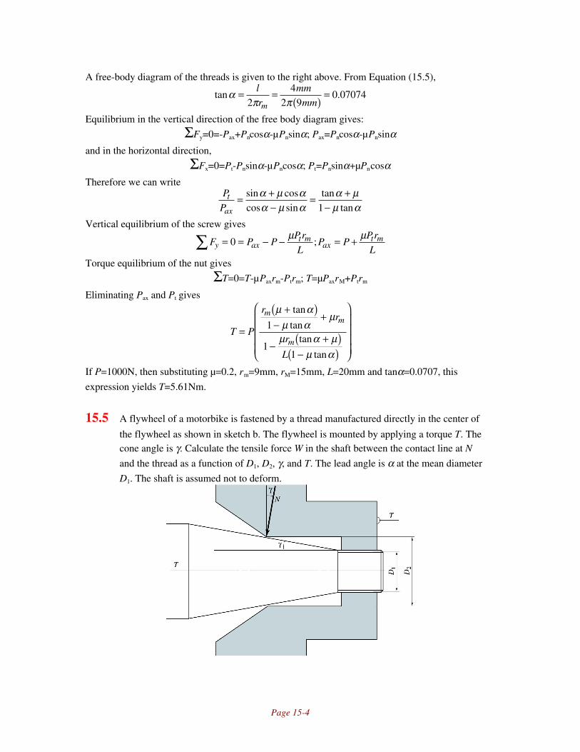
Page 15-4
A free-body diagram of the threads is given to the right above. From Equation (15.5),
tan .απ π
= =( )
=l
r
mm
mmm24
2 90 07074
Equilibrium in the vertical direction of the free body diagram gives:
ΣFy=0=-Pax+Pncosα-µPnsinα; Pax=Pncosα-µPnsinαand in the horizontal direction,
ΣFx=0=Pt-Pnsinα-µPncosα; Pt=Pnsinα+µPncosαTherefore we can write
P
Pt
ax= +
−= +
−sin coscos sin
tantan
α µ αα µ α
α µµ α1
Vertical equilibrium of the screw gives
F P PPr
LP P
Pr
Ly axt m
axt m= = − − = +∑ 0
µ µ;
Torque equilibrium of the nut gives
ΣT=0=T-µPaxrm-Ptrm; T=µPaxrM+Ptrm
Eliminating Pax and Pt gives
T P
rr
r
L
mm
m=
+( )−
+
−+( )
−( )
µ αµ α
µ
µ α µµ α
tan
tantan
tan
1
11
If P=1000N, then substituting µ=0.2, rm=9mm, rM=15mm, L=20mm and tanα=0.0707, this
expression yields T=5.61Nm.
15.5 A flywheel of a motorbike is fastened by a thread manufactured directly in the center of
the flywheel as shown in sketch b. The flywheel is mounted by applying a torque T. Thecone angle is γ. Calculate the tensile force W in the shaft between the contact line at N
and the thread as a function of D1, D2, γ, and T. The lead angle is α at the mean diameter
D1. The shaft is assumed not to deform.

Page 15-5
Notes: This problem is solved by performing torque equilibrium on the flywheel and then using
Equation (15.10) for the screw torque.
Solution:
The forces acting on the shaft are shown above right. Note that when the flywheel is mounted, the
contact slides in the circumferential and the axial direction. Torque equilibrium on the flywheel
gives
T T ND
Tt= = −
−∑ 0
22µ φcos
where Tt is the thread torque and φ is the angle as shown defined by
tantancos
φ αγ
= D
D1
2
Horizontal force equilibrium gives
ΣFx=0=W-Nsinγ-µNsinφcosγ; W=N(sinγ+µsinφcosγ)Substituting this into Equation (15.10) and then the resulting expression into the torque equation
given above yields
TD W WD n
n−
+−
+( )−
=µ φγ µ φ γ
θ α µθ µ α
2 12 20
cos /sin sin cos
cos tan /
cos tan
This could be solved for W if desired.
15.6 To change its oil, a 10-ton truck is lifted a height of 1.7m by a screw jack. The power
screw has Acme threads and a crest diameter of 5 in. with two threads per inch, and the
lead equals the pitch. Calculate how much energy has been used to lift and lower the
truck if the only friction is in the threads, where the coefficient of friction is 0.08
Notes: A ton is taken here as 2000lb, although it may be interpreted as the weight of 1000 kg.
The approach is similar to Problems (15.1) to (15.3), but one must also use Equation (15.12) to
calculate the torque needed to lower the load.
Solution:
For a crest diameter of 5 in, Table 15.2 gives the number of threads per inch as 2, so that the pitch
is 0.5in. From Equation (15.4), the pitch diameter is
dp=dc-0.5p-0.01in=5in-0.5(0.5in)-0.01=4.74inSince the lead, l, equals the pitch, l=0.5 in. From Equation (15.5), α is given by
απ π
=
= ( )
= °− −tan tan
.
..1 1 0 5
4 741 923
l
d
in
inp
From Figure 15.5, it can be seen that β=29°, so from Equation (15.8), θ is
θ α βn =
= °
°
= °− −tan cos tan tan cos . tan .1 1
21 923
29
214 49
The torque to raise the load is given by Equation (15.10) (note that µc=0):

Page 15-6
T Wd
r
kipin
in lb
rp n
nc c=
( ) +( )−
+
= ( ) ( ) ° ° +( )° − °
= −
/ cos tan
cos tan
. / cos . tan . .
cos . . tan .
2
204 74 2 14 49 1 923 0 08
14 49 0 08 1 9235523
θ α µ
θ µ αµ
The energy is the product of the torque and the rotation. To travel 1.7m=66.93in, the screw needs
to rotate 66.93/l=66.93/0.5=133.9revolutions=841.1rad. The energy needed to raise the load is
then
Er=(841rad)(5523in-lb)=4645kip-in or 387kip-ft
The torque to lower the load is obtained from Equation (15.12):
T Wd
r
kipin
in lb
lp n
nc c= −
( ) −( )+
+
= −( ) ( ) − ° °( )° + °
= − −
/ cos tan
cos tan
. / . cos . tan .
cos . . tan .
2
204 74 2 0 08 14 49 1 923
14 49 0 08 1 9232318
µ θ α
θ µ αµ
and the energy needed to lower the load is then
El=(841rad)(2318in-lb)=1950kip-in=162kip-ft
15.7 A single-threaded M32x3.5 power screw is used to raise a 12-kN load at a speed of 25
mm/s. The coefficients of friction are 0.08 for the thread and 0.12 for the collar. The
collar mean diameter is 55 mm. Determine the power required. Also, determine how
much power is needed for lowering the load at 40 mm/s.
Notes: The power is calculated from the torque needed to raise the load or lower the load,
obtained from Equations (15.10) and (15.12), respectively.
Solution:
The bolt designation gives dc=32mm and p=3.5mm. From Equation (15.4) for metric threads,
dp=dc-0.5p-0.25=32mm-(0.5)(3.5mm)-0.25mm=30mm
Since there is a single thread, the lead is the same as the pitch, or l=3.5mm. The torque is givenby Equation (15.10), but first, from Equation (15.5), α is given by
απ π
=
= ( )
= °− −tan tan
..1 1 3 5
302 13
l
d
mm
mmp
Note from Figure 15.5 that β=29°. From Equation (15.8), θ is
θ α βn =
= ° °
= °− −tan cos tan tan cos . tan .1 1
22 13
292
14 49
The torque to raise the load is given by Equation (15.10):

Page 15-7
T Wd
r
kNm m
Nm
rp n
nc c=
( ) +( )−
+
= ( ) ( ) ° ° +( )° − °
+ ( )( )
=
/ cos tan
cos tan
. / cos . tan . .
cos . . tan .
. ..
2
120 030 2 14 49 2 13 0 08
14 49 0 08 2 13
0 055 0 12
261 23
θ α µ
θ µ αµ
Since the lead is l=3.5mm, and the load is raised at 25mm/s, the screw must be rotating at a speed
of ωr=25/3.5=7.14rev/s=44.88rad/s. Therefore the power is the product of torque and angular
velocity, orhpr=Trωr=(61.23Nm)(44.88rad/s)=2748W
The torque to lower the load is given by Equation (15.12) as
T Wd
r
kNm m
Nm
lp n
nc c= −
( ) −( )+
+
= −( ) ( ) − ° °( )° + °
+ ( )( )
= −
/ cos tan
cos tan
. / . cos . tan .
cos . . tan .
. ..
2
120 030 2 0 08 14 49 2 13
14 49 0 08 2 13
0 055 0 12
247 75
µ θ α
θ µ αµ
The lowering speed is ωl=40/3.5=11.43rev/s=71.81rad/s, so the power needed is
hpl=Tlωl=(47.75Nm)(71.81rad/s)=3429W
15.8 A double-threaded Acme power screw is used to raise a 1350-lb load. The outer diameter
of the screw is 1.25 in and the mean collar diameter is 2.0 in. The coefficients of friction are 0.13
for the thread and 0.16 for the collar. Determine the following
a) Required torque for raising and lowering the load
b) Geometrical dimensions of the screw
c) Efficiency in raising the load.
d) Load corresponding to the efficiency if the efficiency in raising the load is 18%.
Notes: This problem is similar to the previous problems, especially Problem 15.2 and 15.7. The
new concepts introduced are the use of a double thread and more in-depth use of the equation for
efficiency (Equation (15.13)).
Solution:
From Table 15.2 on page 671, for a crest diameter of 1.25 in, there are n=5 threads per inch, so
that p=1/n=0.2in, Since this is a double thread, the lead is twice the pitch, or l=0.4in. The pitch
diameter is obtained from Equation (15.4) as
dp=dc-0.5p-0.01=1.25in-0.5(0.2in)-0.01in=1.14in
The torque is given by Equation (15.10), but first, from Equation (15.5), α is given by
απ π
=
= ( )
= °− −tan tan
.
..1 1 0 4
1 146 376
l
d
in
inp
Note from Figure 15.5 that β=29°. From Equation (15.8), θ is

Page 15-8
θ α βn =
= ° °
= °− −tan cos tan tan cos . tan .1 1
26 376
292
14 4
The torque to raise the load is given by Equation (15.10):
T Wd
r
lbin
in in lb
rp n
nc c=
( ) +( )−
+
= ( ) ( ) ° ° +( )° − °
+ ( )( )
= −
/ cos tan
cos tan
. / cos . tan . .
cos . . tan .. . .
2
13501 14 2 14 4 6 376 0 13
14 4 0 13 6 3761 0 0 16 408 1
θ α µ
θ µ αµ
The torque to lower the load is given by Equation (15.12) as
T Wd
r inlblp n
nc c= −
( ) −( )+
+
= −
/ cos tan
cos tan
2233
µ θ α
θ µ αµ
From Equation (15.13), the efficiency is given by
eWl
T
lb in
inlb=
π= ( )( )( )
( )=100
2100 1350 0 4
2 40821 06
.. %
πIf the efficiency is 18% at the same torque, the load is obtained from Equation (15.13) as
eWl
TW
eT
l
inlb
inlb=
π= = ( )( )
( )=100
22100
2 18 408100 0 4
1154;.
π π
15.9 A 25-kN load is raised by two Acme-threaded power screws with a minimum speed of 35
mm/s and a maximum power of 1750 W per screw. Because of space limitations the
screw diameter should not be larger than 45mm. The coefficient of friction for both the
thread and the collar is 0.09. The collar mean diameter is 65mm. Assuming that the loads
are distributed evenly on both sides, select the size of the screw to be used and calculate
its efficiency.
Notes: This problem requires selection of a screw from table 15.2, then analysis of this screw.
Solution:
For a thread diameter of 45mm=1.77 in, the largest screw which can be used is, from Table 15.2,
a 1.75 inch crest diameter screw with 4 threads per inch. Therefore, the pitch is 0.25in=6.35mm.
The pitch diameter is calculated from Equation (15.4) as
dp=dc-0.5p-0.01in=1.75in-0.5(0.25)-0.01in=1.615in=41.02mm
At first, use a single thread so that l=p=6.35mm.
The torque is given by Equation (15.10), but first, from Equation (15.5), α is given by
απ π
=
= ( )
= °− −tan tan
.
..1 1 6 35
41 022 82
l
d
mm
mmp
Note from Figure 15.5 that β=29°. From Equation (15.8), θ is
θ α βn =
= ° °
= °− −tan cos tan tan cos . tan .1 1
22 81
292
14 48

Page 15-9
The torque to raise the load is given by Equation (15.10), using W=12,500N since there are two
screws:
T Wd
r
kNm
m Nm
rp n
nc c=
( ) +( )−
+
= ( ) ( ) ° ° +( )° − °
+ ( )( )
=
/ cos tan
cos tan
.. / cos . tan . .
cos . . tan .. . .
2
12 504102 2 14 48 2 82 0 09
14 48 0 09 2 820 0325 0 09 73 2
θ α µ
θ µ αµ
To raise the load at 35mm/s, the angular velocity ω=35/6.35=5.51rev/s=34.63rad/s. Therefore the
power is
hp=Tω=(73.2Nm)(34.63rad/s)=2540W
This horsepower is too high. Using double threads, the lead is l=2p=12.70mm. Using the same
equations, one obtains α=5.6°, θn=14.4°, Tr=86.24Nm, ω=17.31rad/s, hp=1490W. Therefore, a
double thread screw satisfies the power requirement.
15.10 A screw with Acme thread can have more than one entrance to the thread per screw
revolution. A single thread means that the pitch and lead are equal, but for a double and
triple thread the lead is larger than the pitch. Determine the relationship between the
number of threads per inch n, the pitch p and the lead l.
Notes: If a student has difficulty visualizing this problem, the concept can be illustrated by
wrapping a single string around a pencil, a double thread by wrapping two strings (preferably of
different colors) and a triple thread by wrapping three strings around a pencil.
Solution:
If there are m threads, then the lead is related to the pitch and the threads per inch by
l mpm
n= =
15.11 An M12, coarse pitch, class 5.8 bolt with a
hexagonal nut assembly is used to keep two
machine parts together as shown in sketch c.
Determine the following:
a) Bolt stiffness and clamped member stiffness by
using Wileman’s method.
b) Maximum external load that the assembly can
support for a load safety factor of 2.5.
c) Safety factor guarding against separation of the
members
d) Safety factor guarding against fatigue if a
repeated external load of 10kN is applied to the
assembly.

Page 15-10
Notes: This problem is long only because of the many parts; each part is very straightforward.
The equations used are for part (a), (15.21), (15.25) and (15.26). For part (b), (15.17) and (15.31),
for part (c), (15.32), and for part (d), (15.40).
Solution:
I. Bolt and Member StiffnessNote from the inside front cover that for steel, Es=207GPa and for aluminum Eal=72GPa. From
the sketch we see that Lt=20mm and Ls=40mm. From Table 15.7 on page 689, for a crest diameter
of 12mm and coarse threads, p=1.75mm, At=84.3mm2. From Equation (15.2), ht is
hp mm
mmt = °= ( )
°=0 5
300 5 1 75
301 516
.tan
. .tan
.
From Figure 15.4, the root diameter is:d d h mm mm mmr c t= − ( ) = − ( )( ) =2 0 625 12 2 0 625 1 516 10 105. . . .
Therefore, the bolt stiffness is, from Equation (15.21),
1 4 0 4 0 4 4207
0 04 0 4 0 012
0 012
0 02 0 4 0 010105
0 0101052 2 2 2k E
L d
d
L d
d GPa
m m
m
m m
mb
s c
c
t r
r= + + +
=
( )+ ( )
( )+ + ( )
( )
π π
. . . . .
.
. . .
.
or kb=297.5MN/m. For the member, we use Equation (15.26) with the proper constants taken
from Table 15.3. Referring to the aluminum as member 1 and the steel as member 2, we can write
k Ed A e GPa m e GN mj c alB d Lal c
10 63816 12 3572 0 012 0 7967 0 857= = ( )( )( ) =( )/ . ( ) /. . . /
k Ed A e GPa m e GN mj c steelB d Lal c
20 62873 12 25207 0 012 0 78715 2 644= = ( )( )( ) =( )/ . ( ) /. . . /
Therefore, the joint stiffness, from equation (15.25) is1 1 1 1
0 8571
2 6440 647
1 2k k k GN m GN mk GN m
j j jj= + = + =
. / . /; . /
The stiffness parameter Ck is
Ck
k k
MN m
MN m MN mkb
b j=
+=
+=297 5
297 5 6470 315
. /. / /
.
II. Maximum LoadFrom Table 15.5, for a 5.8 grade bolt, the proof strength is Sp=380MPa, Sut=520MPa and
Sy=415MPa. If we assume this is a reused connection, then from Equation (15.33),
Pi=0.75Pp=0.75SpAt=0.75(380MPa)(84.3mm2)=24,025N~24kN
The maximum load is obtained from Equation (15.31):
nA S P
P CP
A S P
n C
mm MPa kNkNsb
t p i
b kb
t p i
sb k=
−=
−=( )( ) −
( )=
max,max,;
.
. ..
84 3 380 24
2 5 0 31510 2
2
III. Joint SeparationThe safety factor against joint separation is given by Equation (15.32) as
nP
P C
kN
kNsji
j k=
−( ) = ( ) −( )=
max, . ..
124
10 2 1 0 3153 45
IV. Fatigue AnalysisAssuming the threads are rolled, then Kf=2.2 from Table 15.8. We don’t know how the load is
applied, but if we assume the loading is axial, then from Equation (7.7) the endurance limit is

Page 15-11
Se=0.45Su=0.45(520MPa)=234MPa. The prestress is σi=Pi/At=(24kN)/(84.3mm2)=285MPa. The
alternating stress is given by Equation (15.36) as
σak a
t
C P
A
N
mmMPa= = ( ) =0 315 5000
84 318 682
.
..
and the mean stress is calculated from Equation (15.37) as
σmi k m
t
P C P
A
kN N
mmMPa= + = + ( )( ) =24 0 315 5000
84 3303 42
.
..
Therefore, the safety factor against fatigue failure is given by Equation (15.40) as
nS
C KP
A
S
S
P
A
MPa MPa
MPa MPas
ut i
k fa
t
ut
e
m
t
=−
+
=−
( ) ( ) +
=σ 520 285
0 315 2 2 59 31520
23459 31
2 14
. . . .
.
15.12 Find the total shear load on each of the
three bolts for the connection shown in
sketch d. Also, compute the shear
stress and the bearing stress. Find the
area moment of inertia for the 8-mm
thick plate on a section through the bolt
holes.
Notes: An assumption must be made that manufacturing tolerances are such that bolts are loaded
evenly in the vertical direction and that the moment reactions are equally shared by the top and
bottom bolts. Also, the bolts can be taken as points so that the shear stress is uniform over the
cross section.
Solution:
The vertical component of load is 4kN for each bolt if it is shared equally. The moment of
(12kN)(0.2m)=2400Nm is shared by the top and bottom bolts, requiring each to generate a
horizontal force of 2400Nm/((2)(0.032m))=37.5kN. The direction of the force is opposite for the
top and bottom bolts, but this does not matter in terms of the maximum stress. The shear load on
the center bolt is simply 4kN. The top and bottom bolts see a shear of
P kN kN kN= ( ) + ( ) =4 37 5 37 72 2. .
The bolts should be loaded on the shank, not on the threads for such an application, so that the
loaded area is
Ad m
mc= = ( ) = × −π π2 24 2
40 012
41 13 10
..
The central bolt sees a shear stress of
τckN
mMPa=
×=−
4
1 13 1035 44 2.
.

Page 15-12
while the outer bolts see a stress of
τokN
mMPa=
×=−
37 7
1 13 103344 2
.
.The bearing stress (see Equation (15.47)) for the outer bolts is
σ = = −( )( )
= −P
td
kN
m mMPa
37 70 008 0 012
393.
. .
where the negative sign indicates a compressive stress.
The moment of inertia of the cross section is easily calculated using the parallel-axis theorem:
Ith td td
a td
m m m m m mm m m
= − − +
= ( )( ) − ( )( ) − ( )( ) − ( ) ( )( )
3 3 32
3 3 32
12 122
12
0 008 0 13612
0 008 0 01212
20 008 0 012
122 0 032 0 008 0 012
. . . . . .. . .
or I=1.48x10⁻⁶m
4. The bending stress of the plate is
σ = = ( )( )×
=−Mc
IMPa
2400 0 068
1 48 10110 36
.
..
15.13 A coarse-pitch, SAE grade 5 bolt with a hexagonal nut
assembly is used to keep two machine parts together as
shown in sketch e. The major diameter of the bolt is 0.5
in. The bolt and the bottom member are made of carbon
steel. Assume that the connection is to be reused.
Length dimension is in inches. Determine the
following:
a) Length of the bolt.
b) Stiffnesses of the bolt and the member
c) Safety factor guarding against separation of the
members when the maximum external load is 5000lb.
d) Safety factor guarding against fatigue if the repeated
maximum external load is 2500lbf in a released-tension
loading cycle.
Notes: This problem uses the information in previous problems regarding calculation of bolt and
joint stiffness and introduces safety factor calculations from Equations (15.32) and (15.40).
Solution:
The members require 2.2 in of bolt length. Note that we must also allow for the nut and a few
threads beyond the nut. Allowing an extra half-inch of length would lead to a length of 2.7 inches,
so we specify a 2.75 inch length to use a standard bolt size. Therefore, the threaded length is
given by Equation (15.23) as

Page 15-13
Lttot=2dc+0.25in=2(0.5in)+0.25=1.25in
Therefore, Ls=L-Lt=2.75in-1.25in=1.50in. Since the members are a total of 2.2 inches in
thickness, there is only 0.7 inches of thread length in the members, so referring to Figure 15.12,
we take Lt=0.7in
From the inside front cover that for steel, Es=30Mpsi and for aluminum Eal=10.5Mpsi.
From Table 15.6 on page 688, for a crest diameter of 0.50in and coarse threads, n=13 threads/in,
so p=1/13in=0.0769in, At=0.1419in2. From Equation (15.2), ht is
hp in
int = °= ( )
°=0 5
300 5 0 0769
300 0666
.tan
. .tan
.
From Figure 15.4, the root diameter is:d d h in inr c t= − ( ) = − ( )( ) =2 0 625 0 5 2 0 625 0 0666 0 4167. . . . .
Therefore, the bolt stiffness is, from Equation (15.21),
1 4 0 4 0 4 430
1 5 0 4 0 5
0 5
0 7 0 4 0 4167
0 41672 2 2 2k E
L d
d
L d
d Mpsi
in in
in
in in
inb
s c
c
t r
r= + + +
= ( )
+ ( )( )
+ + ( )( )
π π
. . . . .
.
. . .
.
or kb=2.00Mlb/in. The joint stiffness can be calculated from either Equation (15.24) or (15.26),
and we will arbitrarily use the latter. For the member, we use Equation (15.26) with the proper
constants taken from Table 15.3. Referring to the aluminum as member 1 and the steel as member
2, we can write
k Ed A e Mpsi in e Mlb inj c alB d Lal c
10 63816 0 5 1 210 5 0 5 0 7967 5 46= = ( )( )( ) =( )/ . ( . ) / .. . . . /
k Ed A e Mpsi in e Mlb inj c steelB d Lal c
20 62873 0 5 130 0 5 0 78715 16 17= = ( )( )( ) =( )/ . ( . ) /. . . /
Therefore, the joint stiffness, from equation (15.25) is1 1 1 1
5 461
16 174 08
1 2k k k Mlb in Mlb ink Mlb in
j j jj= + = + =
. / . /; . /
The stiffness parameter is given by Equation (15.17) as
Ck
k k
Mlb in
Mlb in Mlb inkb
b j=
+=
+=2 00
2 00 4 080 329
. /. / . /
.
For an SAE grade 5 bolt, Table 15.4 on page 687 gives Su=120ksi, Sy=92ksi and Sp=85ksi. Since
the connection is to be reused, Equation (15.33) gives
Pi=0.75Pp=0.75(AtSp)=0.75(0.1419in2)(85ksi)=9.046kip
Therefore, from Equation (15.32), the safety factor against separation is
nP
P C
kip
kipsji
j k=
−( ) = ( ) −( )=
max,
..
.1
9 0465 1 0 329
2 70
If the repeated maximum external load is 2500lb, in a released-tension cycle, then Pa=Pm=1250lb.
Referring to Table 15.8, we use Kf=3.0 since we are using a standard size where the threads can
be rolled. (A specialty bolt is more likely to be cut.) Therefore, from Equation (7.7), and using
this factor,
S SK
ksie uf
= = ( )( ) =0 45
10 45 120
13
18 0. . .
From Equation (15.40),

Page 15-14
nS
C KP
A
S
S
P
A
ksi kip in
kip
in
kip
in
sut i
k fa
t
ut
e
m
t
=−
+
=− ( )
+
=σ 120 9 046 0 1419
0 3291 250
0 1419
120
18
1 250
0 1419
2 53
2
2 2
. / .
..
.
.
.
.
15.14 An electric-motor driven press (sketch f) has the total press force P=5000 lbf. The screws
are Acme type with β=29°, dp=3in, p=l=0.5in and m=0.05. The thrust bearings for the
screws have dc=5 in and µc=0.06. The motor speed is 1720 rpm, the total speed ratio is
75:1, and the mechanical efficiency is e=0.95. Calculate
a) Press head speed
b) Power rating for the motor
Notes: This problem builds on the approach in Problems 15.1 to 15.8.
Solution:
The speed of the power screw is
Na=1720/75=22.93rpm=144.1rad/s
Therefore the speed of the press head is
v=Nal=(22.93rev/min)(0.5in)=11.47in/min
The load per screw is W=5000lb/2=2500lb. The pitch diameter is obtained from Equation (15.4):
dp=dc-0.5p-0.01=3in-0.5(0.5in)-0.01in=2.74inThe torque is given by Equation (15.10), but first, from Equation (15.5), α is given by
απ π
=
= ( )
= °− −tan tan
.
..1 1 0 5
2 743 32
l
d
in
inp
Note from Figure 15.5 that β=29°. From Equation (15.8), θ is

Page 15-15
θ α βn =
= ° °
= °− −tan cos tan tan cos . tan .1 1
23 32
292
14 47
The torque to raise the load is given by Equation (15.10):
T Wd
r
lbin
in in lb
rp n
nc c=
( ) +( )−
+
= ( ) ( ) ° ° +( )° − °
+ ( )( )
= −
/ cos tan
cos tan
. / cos . tan . .
cos . . tan .. .
2
25002 74 2 14 47 3 32 0 05
14 47 0 05 3 322 5 0 06 752
θ α µ
θ µ αµ
The motor torque is, including the inefficiency in the power transmission,
Tinlb screw screws
motor = ( )( ) =752 2
75
1
0 9521 10
/
..
The power required is
hT N
hppmotor a= =63 000
0 577,
.
15.15 A valve for high-pressure air is shown
in sketch g. The spindle has thread
M12 with a pitch diameter of 10.9 mm,
lead l=1.75mm, and a thread angle of
60°. Derive the relationship between
torque and axial thrust force, and
calculate the axial force against the
seating when the applied torque is
10Nm during tightening. The
coefficient of friction is 0.10.
Notes: This bolt will prevent flow unless an inlet pressure develops a force on the bolt larger than
the axial force during tightening. The analysis requires the use of Equations (15.5), (15.8) and
(15.10).
Solution:
The torque is given by Equation (15.10), but first, from Equation (15.5), α is given by
απ π
=
= ( )
= °− −tan tan
..
.1 1 1 7510 9
2 92l
d
mm
mmp
From Equation (15.8), θ is
θ α βn =
= ° °
= °− −tan cos tan tan cos . tan .1 1
22 92
602
29 97
The torque to raise the load is given by Equation (15.10):

Page 15-16
T Wd
r Wm
m Wrp n
nc c=
( ) +( )−
+
= ( ) ° ° +( )
° − °
= ( )
/ cos tan
cos tan. / cos . tan . .
cos . . tan ..
2 0 0109 2 29 97 2 92 0 129 97 0 1 2 92
0 000913θ α µ
θ µ αµ
And if T=10Nm, then W=11kN
15.16 Derive the expression for the power efficiency of a lead screw with a flat thread (thread
angle β=0°) and find the lead angle a that gives maximum efficiency in terms of the
coefficient of friction. Also, give results if µ=0.1.
Notes: This problem uses equations (15.5), (15.10) and (15.13) to obtain an expression of e in
terms of a. The maximum efficiency is found by taking the derivative of this expression, setting
the derivative equal to zero and solving for a.
Solution:
Note from Equation (15.8) that θ=0. Therefore, from Equation (15.10),
T Wd
rrp
c c=( ) +( )
−+
/ tan
tan
2
1
α µµ α
µ
The collar’s contribution to the lead screw efficiency has noting to do with the thread, and we will
neglect the second term in the parentheses. Therefore, the efficiency is, from Equation (15.13),
eWl
T
l
d
l
dr p p= = −
( ) +( )
=
−+
2 2
1
2
11π π
µ αα µ π α
µ αµ α
tan
/ tan tantancot
But note from Equation (15.5) that tanα=l/πdp, so that
e = −+
11
µ αµ α
tancot
To find the optimum efficiency, take the derivative with respect to α, set to zero and solve for α:
∂∂α
∂∂α
µ αµ α
µ α µα
µ α µα
µ αe = −
+
=− +( )
− −( ) −
+( )=1
1
1 1
10
2 2
2tancot
cotcos
tansin
cot
Therefore the numerator must be zero, so
1 1 2
2 2 21
2 2 2 2+( )( ) = −( )( ) − =
= =
µ α α µ α α α α µ α α
α µ α αµ
cot sin tan cos ; cos sin sin cos ;
cos sin ; tan
For µ=0.1, then α=42°.
15.17 A car manufacturer has problems with the cylinder head studs in a new high-power
motor. After a relatively short time the studs crack just under the nuts, the soft cylinder
head gasket blows out, and the motor stops. To be able to analyze the problem, the car
manufacturer experimentally measures the stiffnesses of the various components. The

Page 15-17
stiffness for all bolts together is 400 N/µm, the stiffness of the gasket is 600 N/µm, and
the stiffness of the cylinder head that compresses the gasket is 10,000 N/µm. By
comparing the life-stress relationships with those for rolling element bearings, the car
manufacturer estimates that the stress amplitude in the screws needs to be halved to get
sufficient life. How can that be done?
Notes: This problem can be solved with a good understanding of the concepts of bolt and joint
stiffnesses and the dimensionless joint parameter.
Solution:When an extra load ∆P is applied to the cylinder head, the force in the stud increases to ∆Pb and
the compression of the gasket and head decrease to ∆P-∆Pb. The extra force in the studs is
∆Pb=kbδ and the force decrease in the gasket is
∆ ∆ ∆P P P
k k
G b
g b
= − =
+
δ
1 1
For a given ∆P and δ, ∆Pb has to be halved by changing the stiffness. From this equation, we can
write
∆ ∆ ∆P P P
k k
kG b
g b
b= + =+
+
δ 11 1
∆∆P
P
k
k kk
b b
g bb
=
++
=
++
=δ
δ 11 1
4001
1 600 1 10 000400
0 4141
/ / / / ,
.
To decrease this to one-half, or 0.2070, the gasket stiffness has to increase. Using the same
equation,1
1 1 10 000400 0 2070 400 1809
/ / ,. ; /
xx N m
++
( ) = =
15.18 A pressure vessel of compressed air is used as an accumulator to make it possible to use a
small compressor that works continuously. The stiffness parameter for the lid around
each of the 10-mm bolt diameters is 900MN/m. The shank length is 20mm. Because the
air consumption is uneven, the air pressure in the container varies between 0.2 and 0.8
MPa many times during the week. After 5 years of use, one of the bolts holding down the
top lid of the pressure vessel cracks off. A redesign is then made, decreasing the stress
variation amplitude by 25%, to increase the life of the bolt to at least 50 years. The stress
variation amplitude is decreased by lengthening the bolts and using circular tubes with
the same cross-sectional area as the solid circular cross section of the bolt to transfer the
compressive force from the bolt head to the lid. Calculate how long the tubes should be.

Page 15-18
Notes: The solution of this problem requires the use of Equations (15.12), (15.16), and (15.21).
Solution:
From Equation (15.12),1 4
207 10
0 02 0 4 0 01
0 01
0 40 0859
664 5 109 2
6
kk N m
bb=
( )( )+ ( ) +
= ×π
. . .
.
..
; . /
From Equation (15.16),
∆P P Pk
k kP Pb b b
b
b j= − =
+−( )max min max min
∆Pb is decreased by 25%, so the new bolt stiffness, kbn, is
k
k k
k
k kbn
bn j
b
b j+=
+=
( )( )+( )
=0 75 0 75664 5 10
664 5 900 100 3186
6
6. ..
..
Solving for kbn yields kbn=420.7x10⁶N/m. Equation (15.21) then gives
1 4 2 0 4 0 42k E
L L d
d dbn
s c
c r=
+ ++
π. .
where L is the length of the tube and the extra screw length. Therefore,
1
420 7 10
4
207 10
0 02 2 0 4 0 01
0 01
0 40 0859
7 089 106 9 23
.
. . .
.
..
; .×
=×( )
+ + ( )( )
+
= × −
πL
L m
The tube should be 7.089 mm long and have a cross sectional area of 78.54mm2.
15.19 A loading hook of a crane is fastened to a block hanging in six steel wires. The hook and
block are bolted together with four 10-mm diameter screws prestressed to 20,000N each.
The shank length is 80 mm and the thread length is 5 mm. The stiffness of the material
around each screw is 1 GN/m. One of the screws of the crane cracks due to fatigue after a
couple of years of use. Will it help to change the screws to 12-mm diameter while other
dimensions are unchanged if the stress variation needs to be decreased by at least 20%?
Notes: This problem uses Equation (15.21) to calculate the bolt stiffness and (15.16) to calculate
the force variation in the bolt.
Solution:
From Table 15.7 on page 689, the tensile stress area for a 10 mm crest diameter screw is 58.0mm2
and the pitch is p=1.5mm. Therefore, from Equation (15.2), ht is
hp mm
mmt = °= ( )
°=0 5
300 5 1 5
301 299
.tan
. .tan
.
From Figure 15.4, the root diameter is:
dr=dc-2(0.625ht)=10mm-2(0.625)(1.299mm)=8.376mm
For a 12-mm crest diameter, At=84.3mm2, p=1.75mm and dr=10.11mm. From Equation (15.21)

Page 15-19
1 4 0 4 0 4 4207
0 08 0 4 0 01
0 01
0 005 0 4 0 008376
0 008376102 2 2 2k E
L d
d
L d
d GPa
m m
m
m m
ms c
c
t r
r= + + +
=
( )+ ( )
( )+ + ( )
( )
π π
. . . . .
.
. . .
.
or k10=169.5MN/m. Similarly for the 12mm bolt,
1 4 0 4 0 4 4207
0 08 0 4 0 012
0 012
0 005 0 4 0 01011
0 01011122 2 2 2k E
L d
d
L d
d GPa
m m
m
m m
ms c
c
t r
r= + + +
=
( )+ ( )
( )+ + ( )
( )
π π
. . . . .
.
. . .
.
or k12=240.0MN/m. The bolt force variation is given by Equation (15.16):
∆ ∆ ∆ ∆Pk P
k k
MN m
MN m MN mP Pb
b
b j10
169 5169 5 1000
0 145=+
= ( )+( )
=. /. / /
.
For the 12 mm bolt:
∆ ∆ ∆ ∆Pk P
k k
MN m
MN m MN mP Pb
b
b j12
240 0240 0 1000
0 194=+
= ( )+( )
=. /. / /
.
The stress variation is the force variation divided by the stress area:
∆ ∆ ∆ ∆σ1010
2
220 145
58 0
10001
2500= =
= ( )−P
A
P
mm
mm
mm Pb
t
.
.
∆ ∆ ∆ ∆σ1212
2
220 194
84 3
10001
2300= =
= ( )−P
A
P
mm
mm
mm Pb
t
.
.
However, if the stress variation is supposed to be reduced 20%, then the stress variation should be
(0.8)(2500)∆P=2000m-2∆P. The twelve millimeter bolts are still insufficient.
15.20 Depending on the roughness of the contacting surfaces of a bolted joint, some plastic
deformation takes place on the tops of the roughness peaks when the joint is loaded. The
rougher the surfaces are, the more pressure in the bolted joint is lost by plastic
deformation. For a roughness profile depth of 20µm on each of the surfaces a plastic
deformation of 6.5 µm can be expected for the two surfaces in contact. For a bolt-and-nut
assembly as shown in Figure 15.13 three sets of two surfaces are in contact. The stiffness
of the two steel plates is 700MN/m when each is 40mm thick. The bolt diameter is 16mm
with metric thread. The shank length is 70mm. The bolt is prestressed to 25kN before
plastic deformation sets in. Calculate how much of the prestress is left after the asperities
have deformed.
Notes: To solve this problem, one must assume that the bolt is prestressed very quickly, and that
plastic deformation in the joint surface asperities takes place much more slowly. Then one can
calculate the stress in the bolt after plastic deformation has relaxed the stress from the initial state.
Solution:
From Table 15.7 on page 689, for a 16mm bolt, the tensile stress area is At=157mm2, p=2mm.
Therefore, from Equation (15.2), ht is
hp mm
mmt = °= ( )
°=0 5
300 5 2
301 732
.tan
.tan
.
From Figure 15.4, the root diameter is:

Page 15-20
dr=dc-2(0.625ht)=16mm-2(0.625)(1.732mm)=13.83mm
Therefore the bolt stiffness is, from Equation (15.21),
1 4 0 4 0 4 4207
0 07 0 4 0 016
0 016
0 01 0 4 0 01383
0 013832 2 2 2k E
L d
d
L d
d GPa
m m
m
m m
mb
s c
c
t r
r= + + +
=
( )+ ( )
( )+ + ( )
( )
π π
. . . . .
.
. . .
.
or kb=428.3MN/m. The deformation of the joint before plastic deformation occurs is:
δ µe eb j
Fk k
kNMN m MN m
m= +
= ( ) +
=1 1
251
428 31
70094 1
. / /.
The plastic deformation reduces this deformation in the bolt. The remaining deformation is (note
that there are three surfaces involved):δp=δe-3(6.5µm)=94.1µm-3(6.5µm)=74.6µm
Therefore the remaining force is
δδ
p pb j
pp
b j
Fk k
Fk k
m
MN m MN mkN= +
=
+( ) =µ+( )
=1 1
1 1
74 61 428 3 1 700
19 8;/ /
./ . / / /
.
15.21 An ISO M12x1.75 class=12.9 bolt is used to
fasten three members as shown in sketch h. The
first member is made of cast iron, the second is
low-carbon steel, and the third is aluminum. The
static loading safety factor is 2.5. Dimensions are
in millimeters. Determine
a) Total length, threaded length, and threaded
length in the joint.
b) Bolt-and-joint stiffness using a 30°cone
c) Preload for permanent connections
d) Maximum static load that the bolt can support
Notes: The student has to determine a reasonable bolt length, and there can be some difference in
the bolt length assumed. This solution uses a bolt length of 80mm. Calculating the bolt stiffness is
as done in previous problems. The joint stiffness is calculated using Equation (15.24) instead of
(15.26) as was done previously.
Solution:
The cone has been sketched in the figure with the sections labeled. The bolt length must be 65
mm plus the length of the nut and space for a few threads beyond the nut. Therefore, we take
L=80mm. From Table 15.7, At=84.3mm2 and p=1.75mm. Therefore, from Equation (15.2), ht is
hp mm
mmt = °= ( )
°=0 5
300 5 1 75
301 516
.tan
. .tan
.

Page 15-21
From Figure 15.4, the root diameter is:
dr=dc-2(0.625ht)=12mm-2(0.625)(1.516mm)=10.105mm
From Table 15.5, Sp=970MPa. From Equation (15.22),
Lt=2dc+6mm=2(12mm)+6mm=30mm
Therefore the shank length is Ls=L-Lt=80mm-30mm=50mm.
Therefore the bolt stiffness is, from Equation (15.21),
1 4 0 4 0 4 4
207
0 05 0 4 0 012
0 012
0 015 0 4 0 01011
0 010112 2 2 2k E
L d
d
L d
d GPa
m m
m
m m
mb
s c
c
t r
r
=+
++
=
( )+ ( )
( )+
+ ( )( )
π π
. . . . .
.
. . .
.
or kb=286.8MN/m. For the joint stiffness, we apply Equation (15.24) for each joint section:
kE d
L d d d d
L d d d d
jii c f
i f i c i c
i f i c i c
=+ −( ) +( )+ +( ) −( )
π α
α
α
tan
lntan
tan
2
2
For section I: cast iron, use Nodular cast iron, E=172GPa (inside front cover), dc=0.012m,
di=1.5dc=0.018m (see text on page 684 explaining the member closest to the nut always has
di=1.5dc), Li=0.025m. Inserting these values and evaluating, kjI=3.448GN/m.
For section II, low carbon steel, E=207GPa, dc=0.012m, di=0.018m+2(0.025m)tan30°=0.0469m,
Li=0.0075m. Therefore, kjII=53.3GN/m.
For section IV, aluminum, E=69GPa, dc=0.012m, di=1.5dc=0.018m, Li=0.030m. Therefore,
kIV=1.311GN/m.
For section III, low carbon steel, E=207GPa, dc=0.012, di=0.018m+2(0.030m)tan30°=0.0526m,
Li=0.0025m. Therefore, kIII=180.4GN/m.
Therefore, the joint stiffness is, from Equation (15.25),1 1 1 1 1 1
3 448
1
53 3
1
1 311
1
180 4k k k k k GN m GN m GN m GN mj jI jII jIII jIV= + + + = + + +
. / . / . / . /
or kj=0.928GN/m. Therefore, from Equation (15.17),
Ck
k k
MN m
MN m GN mkb
b j=
+= =
286 8
286 8 0 9280 236
. /
/ + . /..
The proof load is Pp=AtSp=(84.3mm2)(970MPa)=81.8kN. For a permanent connection, Equation
(15.33) gives Pi=0.90Pp=73.6kN. Therefore, from Equation (15.31),
nA S P
P CP
A S P
n C
mm MPa kNkNs
t p i
b kb
t p i
s k=
−=
−=( )( ) −
( )=
max,max,;
. .
. ..
84 3 970 73 6
2 5 0 23613 8
2
15.22 A pressurized cast iron cylinder shown in sketch I is used to hold pressurized gas at a
static pressure of 8MPa. The cylinder is joined to a low-carbon-steel cylinder head by
bolted joints. The bolt to be used is metric grade 12.9 with a safety factor of 3.
Dimensions are in millimeters. Determine the bolt dimensions and the required number
of bolts.

Page 15-22
Notes: The bolt stiffness is determined from Equation 15.21 after the bolt geometry is
determined. The joint stiffness is found from Equation (15.26), although Equation (15.24) could
be used.
Solution:
Using M36 x 100mm grade 12.9 bolts, from Table 15.5, Su=1220MPa, Sy=1100MPa, Sp=970MPa,
and from Table 15.7, At=817mm2 and p=4mm. Therefore, from Equation (15.2), ht is
hp mm
mmt = °= ( )
°=0 5
300 5 4
303 464
.tan
.tan
.
From Figure 15.4, the root diameter is:
dr=dc-2(0.625ht)=36mm-2(0.625)(3.464mm)=31.67mm
For the 100 mm bolt, the thread length is, from Equation 15.22,
Lt=2dc+6=78mm
Therefore the shank length is 22mm. From the Figure, 33 mm of the thread is exposed in the
member. The bolt stiffness is obtained from Equation 15.21:
1 4 0 4 0 4 4207
0 022 0 4 0 036
0 036
0 033 0 4 0 03167
0 031672 2 2 2k E
L d
d
L d
d GPa
m m
m
m m
mb
s c
c
t r
r= + + +
=
( )+ ( )
( )+ + ( )
( )
π π
. . . . .
.
. . .
.
so that kb=2.208GN/m. The members will be analyzed using the Wileman method. From Table
15.3 on page 684, for cast iron, Ai=0.77871 and Bi=0.61616, E=100GPa, while for carbon steel,
Ai=0.78715 and Bi=0.62873 and E=206.8GPa. The stiffness of the top (carbon steel) joint is, from
Equation (15.26),
k Ed A e GPa m e GN mj c iB d Li c i
10 62873 36 25206 8 0 036 0 78715 14 5= = ( )( )( ) =( )( )/ . /. . . . /
k Ed A e GPa m e GN mj c iB d Li c i
20 61616 36 30100 0 036 0 77871 5 872= = ( )( )( ) =( )( )/ . /. . . /
The total stiffness is then given by1 1 1 1
14 51
5 8724 18
1 2k k k GN m GN mk GN m
jj= + = + =
. / . /; . /
The joint constant is then Ck=kb/(kb+km)=0.3456. Assuming the connection is permanent, which is
usually the case for pressure vessels caps, Equation (15.33) gives Pi=0.9Pp=0.9SpAt=713kN. With
the specified loaded diameter, the applied load is
P pA MPa m MN= = ( )
=8
40 85 4 542π. .
The maximum load that can be taken by a bolt is given by Equation (15.31):
nA S P
P CP
A S P
n C
mm MPa kNkNsb
t p i
k
t p i
sb k=
−=
−=( )( ) −
( )=
maxmax;
..
817 970 713
3 0 345676 7
2
Note that P/Pmax=4.54MN/76.7kN=59.2; use 60 bolts.

Page 15-23
Equation 15.32 then gives
nP
P
nC
kNMN
n
nsji
jk
= =−( )
=−( )
=31
7134 54
1 0 345612 5
max, ..
; .
Therefore, use 60 bolts.
15.23 In the bolted joint shown in sketch j the first member is
made of low-carbon steel, the second member is
aluminum, and the third member is cast iron. Assuming
that the members can be rearranged and the frustum cone
angle is 45°, find the arrangement that can support the
maximum load. Dimensions are in millimeters.
Notes: The maximum load can be achieved by minimizing Ck (see Equation (15.31)), and
therefore maximizing kj. One can solve this problem by considering all alternatives and
calculating the joint stiffness, or one can recognize that symmetry reduces the number of
alternatives by one-half.
Solution:
The maximum load occurs from the smallest value of Ck (see Equation (15.31)). From Equation
(15.17),
Ck
k kkb
b j=
+
So to minimize Ck we want to maximize kj. The stiffness of a joint member is
kE d
L d d d d
L d d d d
jii c f
i f i c i c
i f i c i c
=+ −( ) +( )+ +( ) −( )
π α
α
α
tan
lntan
tan
2
2
We can take any value of dc if our goal is to investigate trends; we take dc=0.020m.
I. Steel-Al-IronFor this case, we have four frustums:
1: low carbon steel, E=207GPa, dc=0.020m, di=1.5dc=0.030m, Li=0.035m, so that k1=15.8GN/m.
2. aluminum, E=69GPa, dc=0.020m, di=0.03+0.035sin45=0.0547, Li=0.0325, so that
k2=13.6GN/m.
3. aluminum, E=69GPa, dc=0.020, di=0.03+0.04sin45=0.0583m, Li=0.0275m, so that
k3=15.88GN/m
4. cast iron, E=172GPa, dc=0.020m, di=1.5dc=0.030m, Li=0.040m, so that k4=12.89GN/m

Page 15-24
Therefore, the stiffness of the member is1 1 1 1 1 1
15 81
213 61
15 881
12 891 2 3 4k k k k k GN m GN m GN m GN mj= + + + = + + +
. / . / . / . /
or kj=3.61GN/m
II. Steel-Iron-Al1: same as above, k1=15.8GN/m.
2: cast iron, E=172GPa, dc=0.020m, di=0.0547m, Li=0.0325m, k2=34.0GN/m
3: cast iron, E=172GPa, dc=0.020m, di=0.03+0.06sin45=0.0724m, Li=0.0075m, k3=118.8GN/m
4: aluminum, E=69GPa, dc=0.020, di=0.03, Li=0.06, k4=4.9GN/m
so that k=3.28GN/m.
III. Al-Steel-Iron1. aluminum, E=69GPa, dc=0.020, di=0.03, Li=0.06, k1=4.9GN/m.
2. steel, E=207GPa, dc=0.02, di=0.03+0.06sin45°=0.0724m, L=0.0075m, k2=143GN/m
3. steel, E=207GPa, dc=0.02, di=0.03+0.04sin45°=0.0583m, L=0.00275m, k3=208GN/m
4. cast iron, E=172GPa, dc=0.02, di=0.03m, Li=0.04m, k4=12.9GN/m
so that kj=3.41GN/m.
Note that all other combinations are the same as one of these. The stiffest member occurs with
aluminum in the center.
15.24 The cylinder shown in sketch k is
pressurized up to 7MPa and is
connected to the cylinder head by
sixteen M24x3 metric grade 8.8 bolts.
The bolts are evenly spaced around the
perimeters of the two circles with
diameters of 1.2 and 1.5m,
respectively. The cylinder is made of
cast iron and its head is made of high-
carbon steel. Assume that the force in
each bolt is inversely related to its
radial distance from the center of the
cylinder head. Calculate the safety
factor guarding against failure due to
static loading.
Notes: This problem is similar to Problem 15.22 in the approach of determining the bolt and joint
stiffness. The maximum load can be calculated using the assumption given in the problem
statement. This problem is open ended in that the student must choose a bolt length, so answers
may vary slightly. This solution uses a bolt length of 80mm.

Page 15-25
Solution:
I. Bolt and Joint Analysis
From Table 15.5, for a grade 8.8 bolt, Sp=600MPa. From Table 15.7, for dc=24mm, At=353mm2
and p=3mm. Therefore from Equation (15.2), ht is
hp mm
mmt = °= ( )
°=0 5
300 5 3
302 598
.tan
.tan
.
From Figure 15.4, the root diameter is:
dr=dc-2(0.625ht)=24mm-2(0.625)(2.598mm)=20.75mm
A reasonable bolt length for the joint and with clearance for the nut is 80mm. From Equation
(15.22),
Lt=2dc+6mm=2(24mm)+6mm=54mm
Therefore Ls=80-54=26mm. Since the combined joint thickness is 55mm, the threaded length in
the members is 55-26=29mm. The bolt stiffness is calculated from Equation (15.21):
1 4 0 4 0 4 4207
0 026 0 4 0 024
0 024
0 029 0 4 0 02075
0 020752 2 2 2k E
L d
d
L d
d GPa
m m
m
m m
mb
s c
c
t r
r= + + +
=
( )+ ( )
( )+ + ( )
( )
π π
. . . . .
.
. . .
.
or kb=1.095GN/m. From Table 15.3, for steel, E=206.8GPa, Ai=0.78715, Bi=0.62873 and for cast
iron, E=100GPa, Ai=0.77871, Bi=0.61616. The joint stiffnesses are:
k Ed A e GPa m e GN mj c iB d Li c i
10 62873 24 25206 8 0 024 0 78715 7 14= = ( )( )( ) =( )( )/ . /. . . . /
k Ed A e GPa m e GN mj c iB d Li c i
20 61616 24 30100 0 024 0 77871 3 06= = ( )( )( ) =( )( )/ . /. . . /
and the joint stiffness is, from Equation (15.25),1 1 1 1
7 141
3 062 14
1 2k k k GN m GN mk GN m
jj= + = + =
. / . /; . /
From Equation (15.17), Ck is
Ck
k k
GN m
GN m GN mkb
b j=
+=
+=1 09
1 09 2 140 338
. /. / . /
.
II. Forces and Safety FactorThe preload for reused connections is obtained from Equation (15.33),
Pi=0.75SpAt=(0.75)(600MPa)(353mm2)=158.9kN
The bolts are placed over two diameters, with eight bolts per circle. The load due to the pressure
is
P=π(1m)2(7MPa)/4=5495kN
Refer to the inner bolt force as P1, the outer as P2. From equilibrium,
8P1+8P2=5495kN
Also, from the assumption given,P
P
D
D1
2
2
1
1 51 2
1 25= = =..
.
Substituting this into the equilibrium equation, P1=381.6kN, P2=305.3kN. The inner bolts are
therefore critical. Using Equation (15.31),
nA S P
P C
mm MPa kN
kNst p i
b k=
−=( )( ) −
( )( )=
max,
.
. ..
353 600 158 9
381 6 0 3380 41
2

Page 15-26
Therefore the design is inadequate.
15.25 A steel plate (sketch l) is riveted to a vertical pillar. The three rivets have a 5/8 inch
diameter and carry the load and moment resulting from the external load of 1950lbf. All
length dimensions are in inches. The yield strengths of the materials are Syrivet=85,000psi
and Syplate=50,000psi. Calculate the safety factors for
a) Shear of rivet when Ssy=0.57Sy.
b) Bearing of rivet
c) Bearing of plate
d) Bending of plate
State how failure should first occur.
Notes: The most time consuming portion of this problem is the statics in order to get the shear
stresses on each rivet. Once the statics is finished, the safety factors are calculated from (15.44),
(15.45), (15.46) and (15.47).
Solution:
I. Statics
The area of each rivet is A=π(5/8in)2/4=0.3068in
2. The figure shows a coordinate system relative
to which lengths are measured. This coordinate system is arbitrary and a different location can be
used without affecting results. The x coordinate of the centroid is:
xx A
A
A in in in
Aini i
i= = − −( ) = −∑
∑2 5 2 5 2 5
30 833
. . ..
The y-coordinate is found to be 0. The distance from the force to the centroid is
16in+2.5in+0.833in =19.33in. The applied torque is
T=(1950lb)(19.33in)=37.7kip-in
The distances from the centroid to the bolts are as follows:
r r in in in inb c= = −( ) + ( ) =2 5 0 833 1 25 2 0842 2. . . .
ro=2.5in+0.833in=3.333in
Since the radius to 0 is the greatest, this will have the largest shear stress and is the rivet that will
be analyzed. If we assume that the area of the rivets is insignificant, the polar moment of inertia
of the rivets is due to the parallel axis theorem, and is
J Ar in in in ini= = ( ) ( ) + ( )[ ] =∑ 2 2 2 2 40 3068 3 333 2 2 084 6 073. . . .

Page 15-27
II. Stress AnalysisThe shear stress due to the torque at a is given by Equation (4.33) as
τ trT
J
in kip in
inksi= = ( ) −( ) =3 333 37 7
6 07320 694
. .
..
The shear stress due to the force is assumed to be shared equally by the three rivets so that
τ pP
A
lb
inksi= = ( ) =3
1950
3 0 30682 119
2..
The shear stress at a due to torsion and due to the force are in the same direction, so that the totalshear stress at 0 is τo=20.69ksi+2.119ksi=22.810ksi. The shear force at 0 is then
Po=τoA=(22.81ksi)(0.3068in2)=7000lbf
III. Failure AnalysisFor shear of rivet, the safety factor is given by Equation (15.45) as:
nS S psi
psissy
o
yrivet
o= = =
( )( )=
τ τ0 4 0 4 85 000
22 8101 49
. . ,
,.
For bearing of the rivet, the normal stress is
σ = =( )( )
=P
td
lb
in inksio 7000
5 8 5 817 92
/ /.
From Equation (15.47), the safety factor against rivet bearing is
nS psi
ksisy= = ( ) =0 9 0 9 85000
17 924 269
. .
..
σFor bearing of the plate, note that the stress is the same (same force, same area) as bearing on the
rivet, but the strength is different, so that the safety factor is
nS psi
ksisy= = ( ) =0 9 0 9 50000
17 922 511
. .
..
σFor bending of the plate at a, we first calculate the moment of inertia as
Iin in in in
in= ( )( ) − ( )( ) =5 8 5 5 8 5 812
6 4983 3
4/ / /.
The moment at 0 is (1950lb)(16in)=31,200in-lb. Therefore, the maximum bending stress at 0 is
σ = = −( )( ) =Mc
I
in lb in
inksi
31 200 2 5
6 498124
, .
.From Equation (15.44), the safety factor against bending is
nS psi
psisy= = ( ) =0 6 0 6 50 000
12 0002 5
. . ,
,.
σThe lowest safety factor is shear of rivet, so this is the failure mode which will occur first.
15.26 The flange of a ship’s propeller shaft is riveted in the radial direction against the hollow
shaft. The outside diameter is 1 m and there are 180 rivets around the circumference,
each with a diameter of 25mm. The rivets are made of AISI 1020 steel and placed in
three rows. Calculate the maximum allowable propeller torque transmitted through the
rivets for a safety factor of 3.

Page 15-28
Notes: The only failure mode which can be analyzed is shear of rivets, since the thickness of the
shaft hasn’t been specified. Equation (15.45) is used for this case.
Solution:
From the inside front cover for 1020 steel, Sy=295MPa. From Equation (15.45),
τπ
π π= = = = ( )( )( )
=4 0 4 0 4
40 4 295 0 025
4 319 32
2 2P
d
S
nP
S d
n
MPa mkN
c
y y c.;
. . ..
Since there are 180 bolts, the maximum shear force that can be supported is
Ptot=180(19.3kN)=3474kN
The maximum torque is therefore
Tmax=Ptot(r)=(3474kN)(0.5m)=1.738MNm
15.27 A rectangular steel plate is connected with rivets to a steel beam as shown in sketch m.
Assume the steel to be low-carbon steel. The rivets have a yield strength of 600MPa. A
load of 24kN is applied. For a safety factor of 3 calculate the diameter of the rivets.
Notes: The problem involves the following steps: 1) Determine the centroid and polar moment
of inertia for the rivet pattern as a function of rivet diameter. 2) Find the rivet with maximum
shear and solve for the shear stress. 3) Calculate the shear stress for the critical bolt.
Solution:
Note the labels added to the figure. The centroid is clearly at the center of the central rivet. The
rivets on the corners have a radius of 120(2)1/2
=169.7mm. The rivets on the center of a side have a
radius of 120mm. Assuming the rivets are small, the polar moment of inertia is
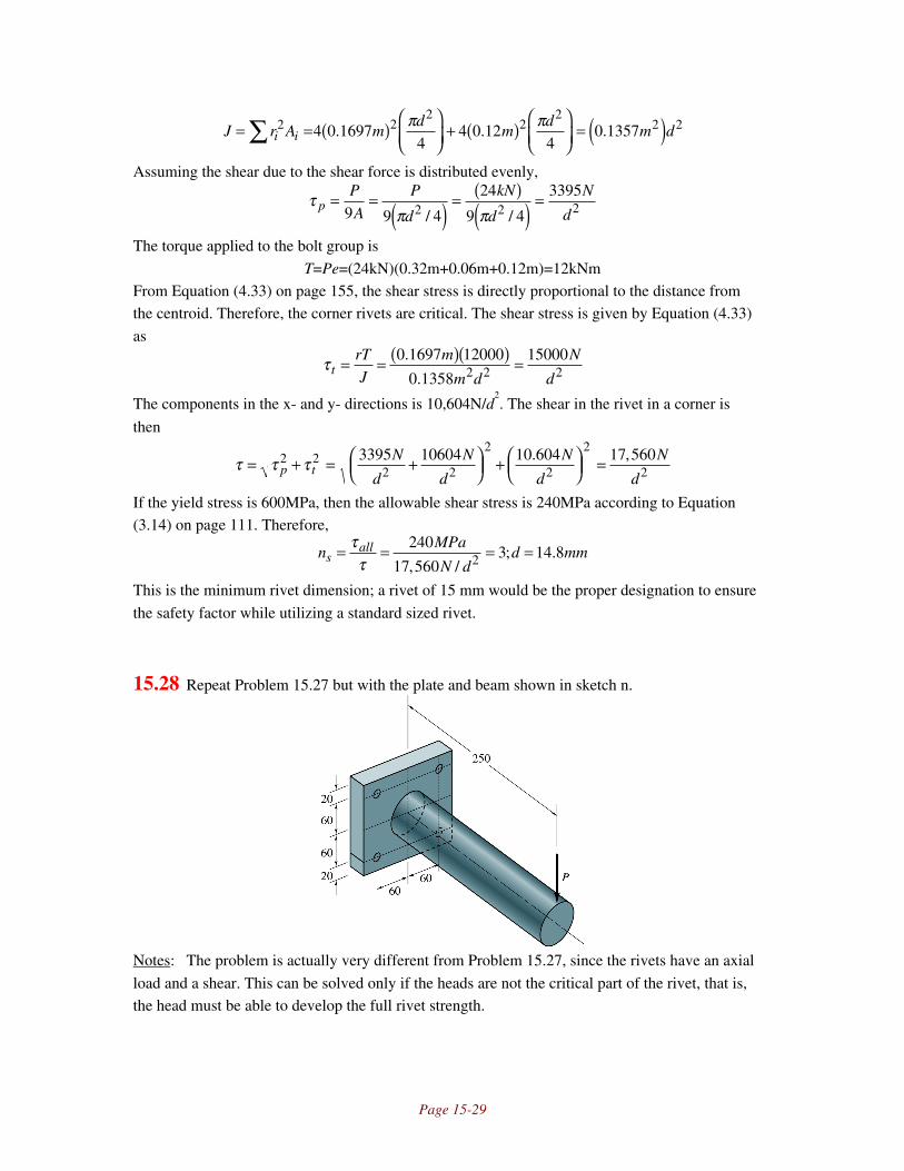
Page 15-29
J r A md
md
m di i= = ( )
+ ( )
= ( )∑ 2 2
22
22 24 0 1697
44 0 12
40 1357. . .
π π
Assuming the shear due to the shear force is distributed evenly,
τπ π
pP
A
P
d
kN
d
N
d= = ( ) =
( )( ) =9 9 4
24
9 4
33952 2 2/ /
The torque applied to the bolt group is
T=Pe=(24kN)(0.32m+0.06m+0.12m)=12kNm
From Equation (4.33) on page 155, the shear stress is directly proportional to the distance from
the centroid. Therefore, the corner rivets are critical. The shear stress is given by Equation (4.33)
as
τ trT
J
m
m d
N
d= = ( )( ) =0 1697 12000
0 1358
150002 2 2
.
.
The components in the x- and y- directions is 10,604N/d2. The shear in the rivet in a corner is
then
τ τ τ= + = +
+
=p tN
d
N
d
N
d
N
d2 2
2 2
2
2
2
23395 10604 10 604 17 560. ,
If the yield stress is 600MPa, then the allowable shear stress is 240MPa according to Equation
(3.14) on page 111. Therefore,
nMPa
N dd mms
all= = = =ττ
240
17 5603 14 82, /; .
This is the minimum rivet dimension; a rivet of 15 mm would be the proper designation to ensure
the safety factor while utilizing a standard sized rivet.
15.28 Repeat Problem 15.27 but with the plate and beam shown in sketch n.
Notes: The problem is actually very different from Problem 15.27, since the rivets have an axial
load and a shear. This can be solved only if the heads are not the critical part of the rivet, that is,
the head must be able to develop the full rivet strength.

Page 15-30
Solution:
The shear stress in each rivet is
τπ π π
= = = = ( )P
d
P
d
N
dN d
/
//
4
4
2400076392 2 2
2
If the plate pivots, then the strain, and therefore the stress, is proportional to the distance from the
bottom edge. Therefore, if the A rivets are the top two rivets and the B rivets are the bottom,
PA=7PB. From moment equilibrium,
2PA(0.14m)+2PB(0.02m)=24000N(0.25m)
Therefore, PA=21,000N, PB=3000N. Therefore the axial stress in rivet A is
σπA
AP
A
kN
dkN d= = =21
426 72
2
/. /
From Equation (2.16),
σ σ σ τ1 2
22
2
22
2 21 26 7
226 7
27 64,
. ..= ±
+ = ±
+ ( )
A AA
d
kN kNkN
or σ1=28.8kN/d2 and σ2=-2.0kN/d
2. The effective stress is, from Equation (6.10) on page 238,
σ σ σ σ σekN
d= − + =1
21 2 2
22
29 8.
Since the safety factor is 3,
nS S d
kNd
kN n
S
kN
MPams
y
e
y s
y= = = ( ) = ( ) =σ
2
29 8
29 8 29 8 3600
0 0122.
;. .
.
To use a standard size, use rivets with a diameter of thirteen.
15.29 The steel plate shown in sketch o is
welded against a wall. Length
dimensions are in inches. The vertical
load is W=4000lbf acts 6.8 inches from
the left weld. Both welds are made by
AWS electrode number E8000. The
allowable shear stress in the weld
should be calculated with ns=3.0.
Notes: The approach in this problem is to first
find the centroid location and distance to the
force from the centroid, then calculate the
stresses at the extreme points on the weld.
Equation (15.54) then gives an equation for the
weld throat depth. This problem is also very
similar to Example 15.11.
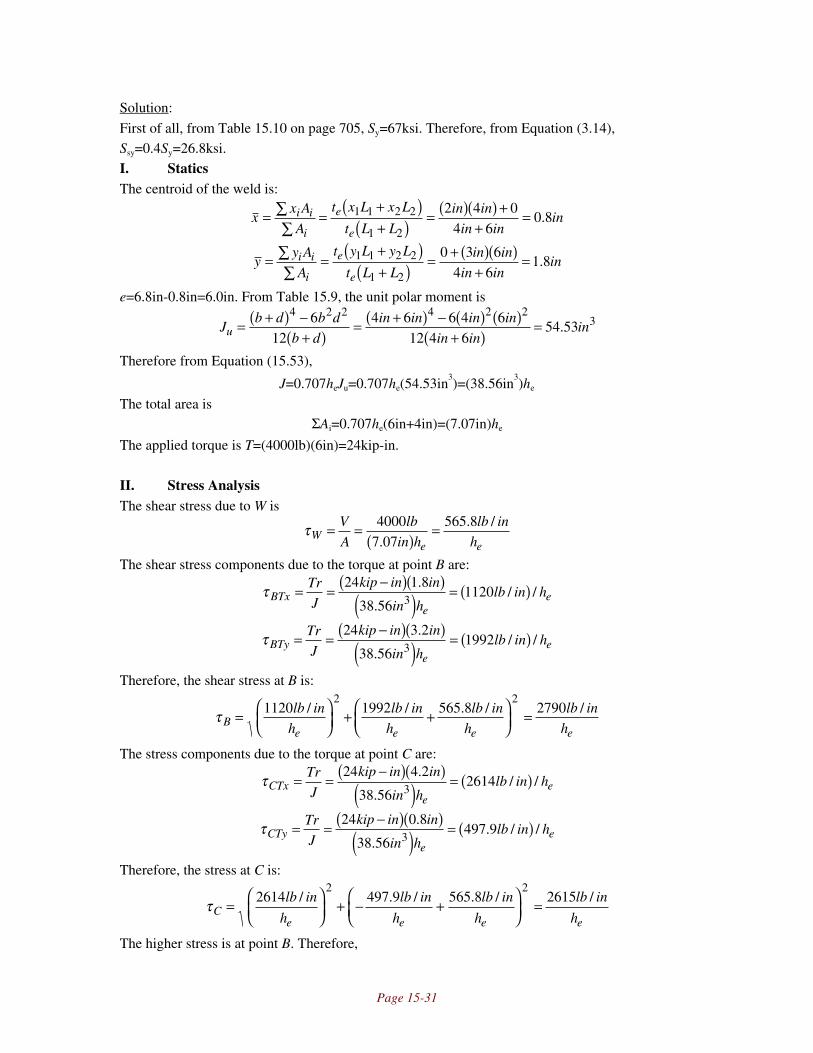
Page 15-31
Solution:
First of all, from Table 15.10 on page 705, Sy=67ksi. Therefore, from Equation (3.14),
Ssy=0.4Sy=26.8ksi.
I. StaticsThe centroid of the weld is:
xx A
A
t x L x L
t L L
in in
in inini i
i
e
e= =
+( )+( ) = ( )( ) +
+=∑
∑1 1 2 2
1 2
2 4 04 6
0 8.
yy A
A
t y L y L
t L L
in in
in inini i
i
e
e= =
+( )+( ) = + ( )( )
+=∑
∑1 1 2 2
1 2
0 3 64 6
1 8.
e=6.8in-0.8in=6.0in. From Table 15.9, the unit polar moment is
Jb d b d
b d
in in in in
in ininu = +( ) −
+( )= +( ) − ( ) ( )
+( )=
4 2 2 4 2 236
124 6 6 4 6
12 4 654 53.
Therefore from Equation (15.53),
J=0.707heJu=0.707he(54.53in3)=(38.56in
3)he
The total area isΣAi=0.707he(6in+4in)=(7.07in)he
The applied torque is T=(4000lb)(6in)=24kip-in.
II. Stress AnalysisThe shear stress due to W is
τWe e
V
A
lb
in h
lb in
h= =
( )=4000
7 07565 8
.. /
The shear stress components due to the torque at point B are:
τBTxe
eTr
J
kip in in
in hlb in h= =
−( )( )( ) = ( )24 1 8
38 561120
3
.
./ /
τBTye
eTr
J
kip in in
in hlb in h= =
−( )( )( ) = ( )24 3 2
38 561992
3
.
./ /
Therefore, the shear stress at B is:
τBe e e e
lb in
h
lb in
h
lb in
h
lb in
h=
+ +
=1120 1992 565 8 27902 2
/ / . / /
The stress components due to the torque at point C are:
τCTxe
eTr
J
kip in in
in hlb in h= =
−( )( )( ) = ( )24 4 2
38 562614
3
.
./ /
τCTye
eTr
J
kip in in
in hlb in h= =
−( )( )( ) = ( )24 0 8
38 56497 9
3
.
.. / /
Therefore, the stress at C is:
τCe e e e
lb in
h
lb in
h
lb in
h
lb in
h=
+ − +
=2614 497 9 565 8 2615
2 2/ . / . / /
The higher stress is at point B. Therefore,

Page 15-32
nS S h
lb inh
lb in
Sssy
B
sy ee
sy= = = = ( ) =τ 2790
33 2790
0 3125/
;/
.
Which is exactly a 5/16 inch weld.
15.30 Two medium-carbon steel (AISI 1040) plates are attached by parallel-loaded fillet welds
as shown in sketch p. E60 series welding rods are used. Each of the welds is 3 in long.
What minimum leg length must be used if a load of 15.0 kN is to be applied with a safety
factor of 3.5?
Notes: The key equation is Equation (15.49).
Solution:
The safety factor for a weld is given by Equation (15.49) as:
nS S h L
Pssy sy e w= =
( )=
τ 1 4143 5
..
From Equation (3.14), Ssy=0.40Sy=0.40(50ksi)=20ksi. Using Lw=6 in and P=15kN=3.37kip,
hkip
ksi inine = ( )( )
( )=
3 5 1 414 3 37
20 60 139
. . ..
However, it is very difficult to lay a bead this small. While this is the minimum bead size for the
required conditions, it is better design practice to specify a 3/16 or 1/4 inch weld, as these are
easier to produce and would give a larger safety factor.
15.31 Determine the weld size required if only the top (AB) portion is welded in Problem
15.30.
Notes: Normally, this would suggest that the weld is loaded in shear due to the force P as well as
a torque T=Pe, where e is half of the width of the plate. It is reasonable for a student to take this
into account, but no dimensions are given for such an analysis. This solution considers only a
shear stress due to the force P, but would have to consider a torque for critical applications.
Therefore, it uses the same approach as problem (15.30).
Solution:
The safety factor for a weld is given by Equation (15.49) as:
nS S h L
Pssy sy e w= =
( )=
τ 1 4143 5
..
Page 15-33
From Equation (3.14), Ssy=0.40Sy=0.40(50ksi)=20ksi. Using Lw=3 in and P=15kN=3.37kip,
hkip
ksi inine = ( )( )
( )=
3 5 1 414 3 37
20 30 278
. . ..
A 3/8 inch weld would be sufficient
15.32 .A bicycle frame is made of welded circular tubes with an outer diameter of 30mm and a
wall thickness of 2.5mm. A cyclist going uphill during a Tour de France race pulls
vertically upward on the right handle to compensate for the large downward thrust on the
right pedal. By doing so he applies a torque of 500 Nm to the bicycle frame. Neglecting
direct shear, how large a part of the tube wall thickness of 2.5 mm has to be covered by
the weld if the shear yield stress is 180MPa in the weld material and 250 Nm is applied to
each weld?
Notes: This problem is very simple; one must merely apply Equation (15.52), solving for the
required inner radius.
Solution:
The polar moment of inertia for the portion of the tube covered by the weld is:
J d d r r m ro i o i i= −( ) = −( ) = ( ) −( )π π π32 2 2
0 0154 4 4 4 4 4.
Equation (15.52) then yields
τ πt
i
Tr
J
Nm m
m rMPa= = ( )( )
( ) −( )=250 0 015
20 015
1804 4
.
.
Solving for ri gives ri=0.0139m or ri=13.9mm. Therefore, 15-13.9=1.1 mm of the tube needs to be
covered by the weld.
15.33 A pressure cooker speeds cooking by utilizing the higher temperature that can be reached
when steam pressure is increased. To speed the cooking of a beef stew, the weight of the
pressure-regulating valve is increased from 100 to 500 g. This action increases the
cooking temperature from 105 to 120°C and the steam pressure from 0.12 to 0.20 MPa.
(1.2 to 2.0 bars). The bottom of the pressure cooker, which is slightly larger than the
outer diameter of the cylindrical wall for stability reasons, is welded with a fillet weld of
class E80 to the cylindrical part. The weld has a leg length of 2 mm and the pressure
cooker outer diameter is 250mm. Calculate the safety factor at 105°C and at 120°C.
Notes: The load on the end of the pressure cooker is the product of the pressure difference from
interior to exterior and the area of the end. Equation (15.49) then gives the shear stress.
Solution:
Page 15-34
From Table 15.10 on page 705, for an E80 electrode, Sy=67ksi=462MPa. Therefore, from
Equation (3.14) on page 111, τall=0.40Sy=0.40(462MPa)=185MPa. The weld length is
πd=π(0.25m)=0.785m.
At 105°C, the internal pressure is 0.12 MPa. The outer pressure is atmospheric pressure,
or 0.101 MPa. Therefore, the force on the pressure cooker bottom is
P pA MPa MPa m N= = −( ) ( ) =∆ 0 12 0 14
0 25 9822. . .π
The shear stress on the weld is given by Equation (15.49) as
τ = = ( )( )( )
=1 414 1 414 9820 002 0 785
0 884. .
. ..
P
h L
N
m mMPa
e w
The safety factor is
nMPa
MPAsall= = =ττ
1850 884
209.
At 120°C, the internal pressure is 0.2MPa, so the force on the pressure cooker bottom is
P pA MPa MPa m N= = −( ) ( ) =∆ 0 20 0 14
0 25 49082. . .π
Therefore, the shear stress on the weld is
τ = = ( )( )( )
=1 414 1 414 49080 002 0 785
4 42. .
. ..
P
h L
N
m mMPa
e w
so that the safety factor is
nMPa
MPAsall= = =ττ
1854 42
42.
15.34 The universal joint on a car axle is welded to the 60-mm outside diameter tube and
should be able to transfer 1500Nm of torque from the gearbox to the rear axle. Calculate
how large the weld leg should be to give a safety factor of 10 if the weld metal is of class
E70.
Notes: The weld leg is calculated from the transmitted torque and resulting shear stress from
Equation (15.52), and the polar moment of the fillet weld using Equation (15.53) and Table 15.9.
Solution:
From Table 15.10 on page 705, for a class E70 weld electrode, the yield strength is
57ksi=393MPa. Therefore, from Equation (3.14) on page 111, τall=0.40Sy=0.40(393MPa)
=157MPa. From Table 15.9, the unit polar moment is
Ju=π(d3/4)=π(0.06m)
3/4=1.697x10
-4m
3
From Equation (15.53), the polar moment of the fillet weld is
J=0.707heJu=0.707he(1.697x10⁻⁴m
3)=1.20x10
-4m
3he
Therefore, from Equation (15.52),
τ te
Tr
J
Nm m
m hMPa= = ( )( )
×( ) =−1500 0 06 2
1 20 10157
4 3. /
.

Page 15-35
Therefore, he=0.002389m or 2.4mm. A 3 or 5 mm weld leg would be a good design designation.
15.35 The steel bar shown in sketch q is welded by an E60XX electrode to the wall. A 3.5 kN
load is applied in the y direction at the end of the bar. Calculate the safety factor against
yielding. Also, would the safety factor change if the direction of load P is changed to the
z direction?
Notes: One must use Table 15.9 for the unit moment of inertia. When the load changes direction,
d and b must be switched in the expression for moment of inertia. Note also that the drawing
designates he=7mm.
Solution:
The leg length is given as 7 mm, with weld length of 50+20=70mm. The geometry gives (from
Table 15.9 on page 703):
Ibd d
mm
yb
b dmm
zd
b dmm
u =+
= ( )( ) + =
=+( )
=+( )
=
=+( )
=+( )
=
4
6
4 20 50 20
6733
2
20
2 20 502 86
2
50
2 20 5017 86
2 22
2 2
2 2
.
.
The moment of inertia is obtained from Equation 15.55:
I=0.707heIuLw=(0.707)(0.007m)(733mm2)(0.070m)=2.54x10⁻⁷m
4
The normal stress is given by Equation 15.57 as
σ = = ( )( )( )×
=−Mc
I
kN m m
mMPa
3 5 0 25 0 01714
2 54 1059 07 4
. . .
..
At the same time, the weld sees a shear due to transverse loading, given by Equation (15.49) as:
τ = = ( ) =1 414 1 414 3 50 007 0 070
10 1. . .
( . )( . ).
P
h L
kN
m mMPa
e w
Performing a Mohr’s circle analysis, the principal stresses are 60.7 MPa and -1.68 MPa. For an
E60XX electrode, Table 15.10 gives the electrode yield strength as 50ksi which equals 345MPa.
The safety factor is then

Page 15-36
nS MPa
MPa MPasy=−
=+( )
=( ) . .
.σ σ1 3
345
60 7 1 685 53
If the force direction was changed to the z-direction (i.e., acting upwards), then Iu can be
calculated as 601.9mm2, I=2.085x10
-7m
4 and σ=135MPa. The shear stress is unchanged. The
resultant safety factor is 2.56, which is a large reduction in the safety factor.
15.36 The bar shown in sketch r is welded to the wall by AWS electrodes. A 5-kN load is
applied at the top of the bar. Dimensions are in millimeters. For a safety factor of 2.5
against yielding, determine the electrode number that must be used and the weld throat
length, which should not exceed 10mm.
Notes: Note that there is a normal stress due to a bending moment and a shear stress due to the
shear force. Therefore, a combined state of stress exists, and the effective stress must be
calculated. The unit moment of inertia is obtained from Table 15.9.
Solution:
Note that the length of the weld is Lw=130mm=0.13m. The shear stress is then obtained from
Equation (15.49):
τ = = ( )( )
=1 414 1 414 50000 13
54 4. ..
. /P
h L
N
h m
kN m
he w e e
From Table 15.9, the unit moment of inertia is
Iu=bd+d2/6=(0.035m)(0.060m)+(0.060m)
2/6=0.0027m
2
From Equation (15.55), the moment of inertia is
I=0.707heIuLw=0.707he(0.0027m2)(0.13m)=0.000248m
3he
The normal stress is then
σ = = ( )( )( ) =Mc
I
N m m
m h
kN m
he e
5000 0 350 0 030
0 000248
2123
. .
.
/
From Equation (2.16),
σ σ σ τ1 2
22
2 2
2 2212
2212
254 4
,/ / . /= ±
+ = ±
+
kN m
h
kN m
h
kN m
he e e
or σ1=(225kN/m)/he and σ2=(-13.1kN/m)/he. The effective stress is , From Equation (2.31)

Page 15-37
σ σ σ σ σee e e e
kN m
h
kN m
h
kN m
h
kN m
h= + −( ) =
+ −
−
−
1
222
1 21 2
2 2 1 2225 13 1 225 13 1/
// . / / . /
or σe=232kN/m/he. The safety factor is
nS
S nkN m
h
kN m
hsall
ey s e
e e= = = ( )
=
σσ; .
/ /2 5
232 580
Note that if he=0.010m, then Sy must be 58MPa=8.3ksi. From Table 15.10, this is met by all
electrodes. Therefore, the following can be stated:
Electrode Number Sy, ksi Sy, MPa he, mm
E60XX
E70XX
E80XX
E90XX
E100XX
E120XX
50
57
67
77
87
107
345
393
462
531
600
738
1.68
1.48
1.26
1.09
0.97
0.79
15.37 AWS Electrode number E100XX is used to weld a bar, shown in sketch s, to the wall.
For a safety factor of 3 against yielding, find the maximum load that can be supported.
What is the maximum stress in the weld and where does it occur? Dimensions are in
millimeters.
Notes: This problem has two different weld thicknesses. For that reason, one must obtain the
moment of inertia by analyzing each weld thickness and its geometry separately.
Solution:
From Table 15.10, an E100XX electrode has a yield strength of Sy=87ksi=600MPa. With a safety
factor of 3, the allowable stress is 200MPa. Refer to the 10mm leg as weld 1, the 6 mm leg as
weld 2. The shear stress from the shear force is, from Equation (15.49),
τ =+
=( )( ) + ( )( )
= ( )−1 414 1 4140 01 0 1 0 006 0 08
955 41 1 2 2
2. .. . . .
.P
h L h L
P
m m m mm P
e w e w
The moment of inertia is from Table 15.9 and Equation (15.55),

Page 15-38
I h I L h I L
mm
m m m m m m
e u w e u w= +( )
= ( ) ( )
( ) + ( )( )( )( )
= × −
0 707
0 707 0 010 05
30 1 0 006 0 04 0 05 0 08 1 268 10
1 1 1 2 2 2
26 4
.
. ..
. . . . . .
The normal stress, from Equation (15.57) is
σ = = ( )( )×
= ( )−−Mc
I
P m m
mm P
0 2 0 025
1 268 1039436 4
2. .
.From Equation (2.16),
σ σ σ τ1 2
22
2 2 2
2 2
2 2
3943
2
3943
2955 4, .= ±
+ =
( )±
( )
+ ( )( )− −
−m P m P
m P
or σ1=(4162m-2)P and σ2=(-219m
-2)P. The effective stress, from
σ σ σ σ σe P m m m m= + −( ) = ( ) + ( ) − ( ) −( )
− − − −12
22
1 21 2 2 2 2 2 2 2
1 2
4162 219 4162 219/ /
or σe=(4275m-2)P. If the maximum allowable stress is 200MPa, then P=46.8kN.
15.38 When manufacturing the fuselage of a commuter airplane, aluminum plates are glued
together with lap joints. Because the elastic deformation for a single plate differs from the
deformation for two plates glued together in a lap joint, the maximum shear stress in the
glue is twice as high as the average shear stress. The shear strength of the glue is 20MPa,
the tensile strength of the aluminum plates is 95MPa, and their thickness is 4.0 mm.
Calculate the overlapping length needed to make the glue joint twice as strong as the
aluminum plate.
Notes: This problem requires the use of Equation (15.50).
Solution:
The tensile force per width is obtained from:
σ σ= = = = ( )( ) =P
A
P
tw
P
wt MPa m kN m; . /95 0 004 380
The glue joint should be twice as strong as the aluminum, or for the glue:P
bkN m kN m= ( ) =2 380 760/ /
From Equation (15.59) and recalling the maximum stress is twice the average stress,
τ ττ τmax
max max; / .= = = =
= ( ) =2
2 2 2 220
760 0 076aveP
bLL
P
b
P
b MPakN m m
or the overlap should be at least 76 mm.
15.39 The ropes holding a children’s swing are glued into two plastic tubes with an inner
diameter of 10 mm and a length of 100 mm. The difference in elasticity between the rope
and the rope plus the plastic tube gives a maximum shear stress 2.5 times as high as the

Page 15-39
mean shear stress in the glue. The glue is an epoxy type with an ultimate shear strength of
12MPa. How heavy can the person on the swing be without overstressing the glue if the
speed of the swing at its lowest point is 6.5 m/s and the distance from the center of
gravity of the person to the fastening points of the ropes is 2m? The safety factor is 10.
Notes: The load is obtained from the produce of the person’s mass and the total accelleration
(gravity plus radial).
Solution:
The total load on the two ropes is
P m g mv
rm m s
m s
mm s ma a a a= + = + ( )
= ( )
22
229 81
6 52 0
30 93. /. /
.. /
The load per rope is then (15.47m/s2)ma. The ultimate shear strength of the glue is 12MPa, so the
maximum mean shear stress is 12/2.5=4.8MPa. The force which the glue can support is then:
Pg=τA=τ(πdL)=(4.8MPa)π(0.01m)(0.1m)=15kN
Since the safety factor is 10, the maximum weight of the person is
10 154 7 1515
154 7972P P m kN m
kN
m skgg a a= = = =; . ;
. /
15.40 A fishing rod is made of carbon fiber reinforced plastic tube. To get optimum elastic
properties along the length of the rod, and to therefore be able to make long and accurate
casts, the concentrations of the fibers in the various parts of the rod have to be different.
It is necessary to scarf joint the rod parts. The tensile strength of the epoxy glue joint is
10MPa and its shear strength is 12.5MPa. These strengths are independent of each other.
Find the optimum scarf angle to make the rod as strong as possible in bending.
Notes: This requires Equation (2.13) and (2.14) to find the optimum scarf angle.
Solution:
The largest stress is at the outer fibers of the fishing rod, and is σ=Mc/I. There are no other stress
components. The normal stress at some angle θ to the surface is given by Equation (2.13) and the
shear stress by Equation (2.14):
σ σ θ θθ = =yMc
Isin sin2 2
τσ
θ θ θ θθ = = =y Mc
I
Mc
I22
22sin sin sin cos
Since the allowable normal stress is 10MPa, and the allowable shear stress is 12 MPa, and these
are independent of each other, the best design will simultaneously achieve the allowable normal
and tensile stress. Therefore,Mc
IMPasin2 10θ =

Page 15-40
Mc
IMPasin cosθ θ =12
The first equation divided by the second yields:Mc
IMc
I
MPa
MPa
sin
sin cos
sincos
tan ; .
21012
39 8θ
θ θ
θθ
θ θ= = = = °

Page 16-1
Chapter 16 • Springs
16.1 A guitar string is made of ASTM A228 steel music wire. To get the correct tone from thestring, a tension of 200N has to be applied. When the string breaks, it is replaced by astring made of ASTM B159 phosphor bronze. What tension will the new string need toget the same tone if the string diameter is the same?
Solution:
If the mass per length is aρ, and there is negligible bending stiffness, vertical force equilibriumgives (see free body diagram above)
F∂ 2y
∂x2 dx = aρdx∂2y
∂t2
This has the solution
y = Asin ωtsinπxL
where
ω = πL
Faρ
= π FmaL
Therefore, for the two strings,
ω2L
π 2 = F1
m1= F2
m2; F1 = m1
m2F2 = ρ1
ρ2F2
From Table 16.1 on page 738, the density of phosphor bronze is 0.320lb/in3. The density of steel
wire is 0.283lb/in3. Therefore the tension needed for phosphor bronze is:
F = 0.32lb / in3
0.283 lb / in3
200N( )= 226N
16.2 A tuning fork is made of ASTM A227 steel and vibrates at an eigenfrequency of 400 Hz.To avoid corrosion, the material is changed to phosphor bronze. At what frequency willthe tuning fork vibrate?
Solution:
From the figure, summing forces:

Page 16-2
T + ∂T∂x
dx − T − aρdx∂2 y
dt2
;
∂T∂x
dx = aρdx∂2y
dt2
From moment equilibrium:
M + ∂M∂x
dx − M − Tdx = 0;∂M∂x
= T
Taking the derivative with respect to x, then substituting for ∂T/∂x,
∂ 2M
∂x 2 = ∂T∂x
= aρ ∂ 2y
∂t2
This has the solution
y = y0 sinπx2L
sinω t
In addition, from Equation (5.3),
M = −EI∂ 2y
∂x2 ;∂ 2M
∂x2 = −EI∂4 y
∂x4 = aρ ∂ 2y
∂t2
Substituting for y and solving for ω,
ω2 = EIaρ
π2L
4
; ω = π2
4L2EIaρ
For the two materials, the ratio of the frequencies isω1
ω2= E1
E2
ρ2
ρ1Therefore, if a b subscript denotes bronze and an s subscript is steel,
ωb = ωsEb
Es
ρs
ρb= 400Hz( ) 15MPa
30MPa0.283lb / in3
0.32 lb / in3 = 266Hz
16.3 An overflow valve, shown in sketch a, has a piston diameter of 15mm and a slit length of5 mm. The spring has a mean coil diameter D=10mm and wire diameter d=2mm. Thevalve should open at 1 bar pressure and be totally open at 3 bar pressure when the springis fully compressed. Calculate the number of active coils, the free length and the pitch ofthe spring. The shear modulus for the spring material G=80GPa. The spring ends aresquared and ground. Determine the maximum shear stress for this geometry.
Notes: The number of active coils is found from Equation (16.15). Equations from Table 16.3 areused for solid length, free length, pitch, and number of total coils. The maximum shear stress iscalculated from Equation (16.9).
Solution:The piston area is

Page 16-3
A =πd p
2
4= π 0.015m( )2
4= 1.767× 10⁻⁴ m2
When the pressure is one bar (0.1MPa), the valve starts to open. The force associated with this
pressure is (1.767x10⁻⁴m2)(0.1MPa)=17.7N. When the pressure is 3 bar (0.3MPa), the force is
53.0N, and the spring deflects a further 5mm=0.005m. Note that from Equation (16.6),C=D/d=10/2=5. Therefore, from Equation 16.15,
δ t = 8PC3Na
Gd; Na = Gdδt
8PC3 = 80GPa( ) 0.002m( ) 0.005m( )8 53.0 N −17.7N( ) 5( )3 = 22.6
The stiffness of the spring, from Equation (16.19) is
k = Pδ t
= 53.0 N −17.7N0.005m
= 7060N / m
Therefore, the spring From Table 16.3, for squared and ground ends,Nt=Na+2=24.6
Ls=d(Nt)=(0.002m)(24.6)=0.0492mWe know that at 53.0N, the spring is at the solid length of 0.0492m. When this load is removed,the deflection is δ=P/k=53.N/7060N/m=0.00751m. Therefore the free length is
Lf=Ls+ds=(0.0492m)+0.0075m=0.0567mFrom Table 16.3, the pitch is
p =l f − 2d
Na= 0.0567m − 2(0.002m)
24.6= 0.00233m = 2.33mm
The maximum shear stress is obtained from Equation (16.11) after the curvature shear correctionfactor is calculated as Kw=(4C-1)/(4C-4)+0.615/C=1.31,
τmax =8DKwP
πd3 =8 0.010m( ) 1.31( ) 53.1N( )
π 0.002m( )3 = 221MPa
16.4 A helical compression spring has mean coil diameter D=90mm and wire diameterd=15mm. The spring has 12 active coils. Derive the equation for the spring deflection andcalculate it for P=4000N. Also, find the shear stress in the wire if the stress concentrationfactor Ki=1.26. The shear modulus of elasticity is G=80GPa.
Notes: The derivation uses equilibrium for a portion of the wire combined with Equation (4.31).The shear stress is calculated from Equation (16.5) and using the stress concentration factorgiven.
Solution:
Consider a small portion of a wire, shown in the sketch. Taking momentequilibrium,
M=PD/2
From Equation (4.31),
θ = MlGJ
= P D / 2( )LGJ
; dθ = P D / 2( )dLGJ
= P D / 2( ) D / 2( )dγGJ
= PD2dγ4GJ
For a circular cross section, J=πd4/32, so

Page 16-4
dθ = PD2dγ4GJ
= 8PD2
πd4Gdγ
Notice from the sketch that the change in length is dδ=(D/2)dθ, so that
dδ = D2
dθ = 4PD3
πd 4Gdγ
The total deflection is
δ = dδ∫ = 4PD3
πd4Gdγ =
0
2πNa
∫ 4PD3
πd 4G2πNa( ) = 8PD3Na
d4G= 8PC3Na
dG
where the substitution C=D/d has been used. For P=4000N, D=0.09m, d=0.015m, Na=12 andG=80GPa, C=D/d=6 and the deflection is
δ = 8PC3Na
dG=
8 4000N( ) 63( ) 12( )0.015m( ) 80GPa( ) = 0.0691m = 69.1mm
The maximum shear stress is obtained from Equation (16.5) combined with the stressconcentration factor as:
τmax = Ki 8PD
πd3 = 1.26( ) 8( ) 4000N( ) 0.090m( )π 0.015m( )3 = 342MPa
16.5 A vehicle has individual wheel suspension in the form of helical springs. The free lengthof the spring lf=360mm and the solid length ls=160mm at a compressive force of 5000N.The shear modulus G=80GPa. Use D/d=9 and calculate the shear stress for pure torsionof the spring wire. The spring ends are squared and ground. Find Na, p, d, D, and τmax.
Notes: An equation for the number of active coils as a function of wire diameter is obtained fromTable 16.3. The deflection equation then gives another equation containing number of active coilsand wire diameter, which can then be solved. The remainder of the terms are then calculated instraightforward fashion similar to Problem 16.3. The maximum shear stress is obtained fromEquation (16.5).
Solution:From Equation (16.15), and going from the solid to free length so that d=0.200m, P=5000N, C=9and G=80GPa gives
δ t = 8PC3Na
Gd;d = 8PC3
Gδ tNa =
8 5000N( ) 93( )80GPa( ) 0.20m( ) Na = 0.00182m( )Na
From Table 16.3 for squared and ground ends, the free length and solid length equations givels=dNt=d(Na+2)
Substituting d=(0.00182m)Na givesLs = 0.00182m( )Na Na + 2( ) = 0.160m; Na = 8.43
Therefore, d=0.0153m=15.3mm. Therefore, since C=9, Equation (16.6) gives D/d=9;D=9d=0.138m=138mm. From Table 16.3, the pitch is obtained as
p =l f − 2d( )
Na= 0.36m − 2 0.0153m( )
8.43= 0.0391m = 39.1mm
The transverse shear factor is Kd=1, since pure torsion is specified. Therefore the maximum shearstress is obtained from Equation (16.5) as
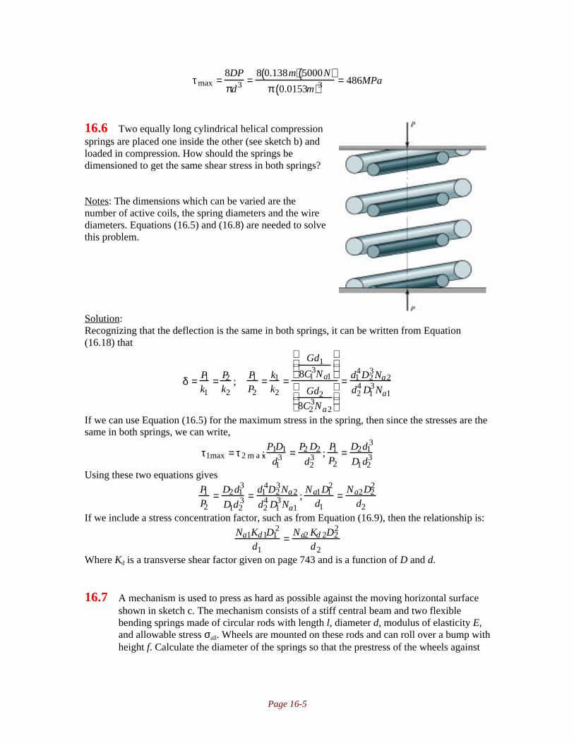
Page 16-5
τmax =8DP
πd3 =8 0.138m( ) 5000N( )
π 0.0153m( )3 = 486MPa
16.6 Two equally long cylindrical helical compressionsprings are placed one inside the other (see sketch b) andloaded in compression. How should the springs bedimensioned to get the same shear stress in both springs?
Notes: The dimensions which can be varied are thenumber of active coils, the spring diameters and the wirediameters. Equations (16.5) and (16.8) are needed to solvethis problem.
Solution:Recognizing that the deflection is the same in both springs, it can be written from Equation(16.18) that
δ = P1
k1= P2
k2;
P1
P2= k1
k2=
Gd1
8C13Na1
Gd2
8C23Na2
= d14D2
3Na2
d24 D1
3Na1
If we can use Equation (16.5) for the maximum stress in the spring, then since the stresses are thesame in both springs, we can write,
τ1max = τ2 m a x;P1D1
d13 = P2 D2
d23 ;
P1
P2= D2d1
3
D1d23
Using these two equations gives
P1
P2= D2d1
3
D1d23 = d1
4D23Na2
d24 D1
3Na1;
Na1D12
d1= Na2D2
2
d2If we include a stress concentration factor, such as from Equation (16.9), then the relationship is:
Na1Kd1D12
d1= Na2 Kd 2D2
2
d2Where Kd is a transverse shear factor given on page 743 and is a function of D and d.
16.7 A mechanism is used to press as hard as possible against the moving horizontal surfaceshown in sketch c. The mechanism consists of a stiff central beam and two flexiblebending springs made of circular rods with length l, diameter d, modulus of elasticity E,and allowable stress σall. Wheels are mounted on these rods and can roll over a bump withheight f. Calculate the diameter of the springs so that the prestress of the wheels against

Page 16-6
the moving surface is as high as possible without plastically deforming the springs whenthe bump is rolled over. The deflection of a spring is shown in sketch d.
Notes: This problem shows that cantilevered beams can be considered as springs. Therelationship between force and deflection can de derived using the approach in Chapter 5, but thisproblem uses the result given in the first row of Table 5.1 on page 193. The bending stress givesthe requirement for P in terms of δ, which is differentiated, set to zero and solved for d to obtainthe optimum diameter.
Solution:We want to maximize the force with respect to cantilever diameter. Because of symmetry, theloads and deflections for the two wheels are equal, or P1=P2=P. There is an extra force caused bythe bump, ∆P=∆P1=∆P2. Also, the deflections are δ1=δ2=f/2. For a cantilever with a load at theend, the relationship between deflection at the end and the load is obtained from the first row ofTable 5.1 on page 193, using a=l,
δ = − P6EI
l − l( )3 − l3 + 3l3[ ] = − Pl3
3EITherefore,
f2
= ∆Pl3
3EI;∆P = 3EIf
2l3 = 3Efπd4
128l3
The bending moment at the end of the cantilever is M=(P+∆P)l, but also since σ=Mc/I,
l P + ∆P( )=σI
lc; P =
σI
lc− ∆P =
σ πd4 / 6 4( )ld / 2
−3Efπd4
128l3=
σπd 3
32l−
3Efπd4
128l3
Therefore, taking the derivative and setting equal to zero, then solving for d:
∂P∂d
= ∂∂d
σπd3
32 l− 3Efπd4
128l3
=
3σπd2
32l− 3Efπd3
32l3= 0 ; 3σd2 = 3Efd3
l2 ; d = σ l2
Ef
The maximum force can be found by substituting this into the expression for P:
Pmax = σπd3
32 l− 3Efπd4
128l3=
σπ σ l2 / Ef( )3
32 l−
3Efπ σl2 / Ef( )4
128l3= πσ4 l5
128E3 f3
16.8 A helical compression spring is used as a catapult. Calculate the maximum speed of abody weighing 10kg being thrown by the catapult, given that τmax=500MPa, D=50mm,d=8mm, Na=20 and G=80GPa.
Page 16-7
Notes: Equation (16.11) will allow for the calculation of the maximum force in the compressionof the spring. The stored energy can then be calculated and equated to the kinetic energy of thebody after launch.
Solution:For this spring, Equation (16.6) gives C=50/8=6.25. Therefore, the Transverse shear factor is
Kd=(C+0.5)/C=6.75/6.25=1.08.Equation (16.9) then gives:
τmax = 8DKdP
πd3 ; P = τmaxπd3
8DKd= 500MPa( )π 0.008m( )3
8 0.050m( ) 1.08( ) = 1860N
From Equation (16.18), the deflection under this load is
δ t = 8PC3Na
Gd= 8 1 8 6 0N( ) 6.25( )3 20( )
80GPa( ) 0.008m( ) = 0.114m = 114mm
The energy stored in the spring is U=Pδ/2=(1860N)(0.114m)/2=106 Nm. Since the kinetic energyof the object is mv
2/2, the maximum velocity is found as
U = K ; 1
2mv2 = 106Nm; v =
212Nm
m=
212Nm
10kg= 4.60m / s
16.9 A spring is preloaded with force Pi and is then exposed to a force increase whereby theshear stress increases to a certain value τ. Choose the mean coil diameter D to maximizethe energy adsorption caused by the force increase.
Notes: The approach is to obtain an equation of energy as a function of spring diameter, then setthe derivative of this expression equal to zero. This solution uses Equation (16.5), althoughEquation (16.9) or (16.12) could be used with an increase in complexity.
Solution:The energy stored in a spring at a load P is
U =Pδ2
=P P / k( )
2=
P2
2k=
4P 2C3Na
Gd=
4P2D3Na
Gd 4
If the shear stress is τ, then from Equation (16.5),
τ = 8DP
πd3 ; P = τπd3
8DTherefore, the energy stored between the two conditions described is
U =
4τπd3
8D
2
D3Na
Gd 4 − 4Pi2D3Na
Gd4 = π 2τ 2d2NaD16G
− 4Pi2D3Na
Gd4
Taking the derivative, setting equal to zero and solving for D yields:
dUdD
= π 2τ 2d2Na
16G− 12Pi
2D2Na
Gd 4 = 0;D = π8 3
τd3
Pi
16.10 A compression spring made of music wire is used for static loading. Wire diameterd=1.4mm, coil outside diameter D0=12.1mm, and there are eight active coils. Also,assume that the spring ends are squared and ground. Find the following:

Page 16-8
a) Spring rate and solid lengthb) Greatest load that can be applied without causing a permanent set in excess of 2%c) Spring free length with load determined in part b that causes the spring to be solid.d) Whether buckling is a problem. If it is, recommend what you would change in theredesign.
Notes: The spring rate is obtained from Equation (16.19), and other equations are taken fromTable 16.3. The strength of the wire is obtained from Equation (16.2) and data from Table 16.2.Whether or not buckling is a problem is assessed from Figure 16.7.
Solution:Note from Figure 16.2(b), that the spring diameter D=D0-d=10.7mm=0.0107m. Therefore, C is,from Equation 16.6, C=D/d=10.7/1.4=7.64. From Table 16.1 on page 738,G=11.5Mpsi=79.3GPa. The spring rate is obtained from Equation (16.19):
k = Gd
8C3Na 1+ 0.5
C2
= 79.3GPa( ) 0.0014m( )8 7.64( )3 8( ) 1+ 0.5
7.642
= 3850N / m
From Table 16.3 on page 746, using squared and ground ends, the solid length isLs=dNt=d(Na+2)=0.0014m(8+2)=0.014m
From Table 16.2 on page 739 for music wire, Ap=2170MPa and m=0.146. Therefore, fromEquation (16.2),
Sut =Ap
d m = 2170MPa
1.4( )0.146 = 2066MPa
From Equation (16.3),Ssy=0.4Sut=0.4(2066MPa)=826.4MPa
The transverse shear factor is Kd=(C+0.5)/C=8.14/7.64=1.065, so that Equation (16.9) gives
τmax = 8DKdP
πd3 ; P = τmaxπd3
8DKd= 826.4MPa( )π 0.0014m( )3
8 0.0107m( ) 1.065( ) = 78.1N
The deflection caused by this load is
δ = Pk
= 78.1N3850N / m
= 0.0203m = 20.3mm
Therefore, the free length is lf=ls+δ=14mm+20.3mm=34.3mm.For this spring, δ/lf=20.3/32.1=0.63, and lf/D=34.3/10.7=3.21 Notice from Figure 16.7 on
page 748 that buckling is not a problem for this spring.
16.11 Design a helical compression spring made of music wire with squared and parallel ends.Assume a spring index C=12, a spring rate k=300N/m, and a force to solid length of 60N.Find the wire diameter and the mean coil diameter while assuming a safety factor ns=1.5.Also, check whether buckling is a problem. Assume steady loading.
Notes: The spring wire diameter is found from the stress requirements, and Equation (16.11) isused for the shear stress. The strength of the wire is obtained from Equation (16.2) and data fromTable 16.2. Whether or not buckling is a problem is assessed from Figure 16.7.
Solution:

Page 16-9
From Table 16.1 on page 738 for music wire, G=11.5Mpsi=79.3GPa. From Table 16.2 on page739 for music wire, Ap=2170MPa and m=0.146. Therefore the strength of the wire in shear is,from Equation (16.2) and (16.3),
Ssy = τall = 0.4 Sut = 0.4Ap
d m = 0.42170MPa
d0.146 = 868MPa
d 0.146
where d is in millimeters. The transverse shear factor is Kd=(C+0.5)/C=12.5/12=1.04. Therefore,the maximum shear stress is, from Equation (16.11),
τmax = 8DKdP
πd3 = 8CKdP
πd2 = 8 1 2( ) 1.04( ) 60N( )πd2 = 1907N
d2
The safety factor is 1.5, so that (note the care to keep consistent units)
ns = τall
τmax= 868MPa( )
d 1000mm / m( )( )0.146d2
1907N=1.5; d = 0.00190 m =1.90mm
Therefore D=1.90mm(12)=22.8mm. From Equation (16.19),
k =Gd
8C3Na 1 + 0.5
C2
; Na =Gd
8C3k 1 + 0.5
C2
=79.3GPa( ) 0.00190m( )
8 123( ) 300N / m( ) 1 + 0.5
12
= 36.2
From Table 16.3, Nt=Na+2=38.2 coils, ls=Ntd=(38.2)(0.00190m)=0.0726m. The deflection fromfree to solid length is
δ = Pk
= 60N300N / m
= 0.2m = 200mm
Therefore the free length is lf=ls+δ=0.0726m+0.2m=0.2726m. Note thatlf/D=0.2726/0.0228=11.96, and ls/lf=0.2/0.2726=0.73. From Figure 16.7, it is clear that the springwill buckle unless constrained or supported.
16.12 Two helical springs with spring ratesof k1 and k2 are mounted one inside the other asshown in sketch e. The difference in unstressedlength is ∆ and the second spring is longer. Aloose clamping device is mounted at the top ofthe springs so that they are deformed andbecome equal in length. Calculate the forces inthe two springs. An external force P is the loadapplied thereafter to the spring. In a diagramshow how the spring forces vary with P.
Notes: The shorter spring elongates, the longer spring compresses, and the total deflection is ∆.Each spring has the same force. This is enough to solve the problem.
Solution:From equilibrium on the clamping device, each spring has the load P0. Also, the compressivedisplacement in the longer spring and the elongation in the shorter add up to ∆. Therefore,
δ1+δ2=∆From Equation (16.18),

Page 16-10
P0
k1+ P0
k2= ∆; P0 = ∆ k1k2
k1 + k2If there is an external force P, equilibrium requires
P1-P2=PBut the deflections must be the same. Since there is a prestress P0, we can write
P1 = P0 + k1Pk1 + k2
P2 = P0 −k2P
k1 + k2The forces in each spring as a function of external load are as follows:
16.13 Using Eqs (16.5) and (16.18) describe how the spring diameter can be chosen to give aslow a maximum shear stress as possible.
Notes: It is helpful to consider the circumstance where there is a load P, and a change in load ∆Pleads to a deflection δ. Then use the suggested equations to obtain an expression for D.
Solution:A deformation increase of δ gives a force increase of ∆P=kδ and a total force of P+∆P.Therefore, from Equation (16.5),
τmax = 8 P + ∆P( )D
πd3 = 8DP
πd3 + 8D∆P
πd3
From Equation (16.18),
∆P = kδ = Gdδ8C3Na
= Gd4δ8D3Na
Therefore, the maximum shear stress is
τmax = 8DP
πd3 + 8GdδπNa D2
Taking derivative with respect to D, setting equal to zero and solving,
∂τ∂D
=8P
πd3 −2Gdδ
πNaD3 = 0; 8P
πd3 =2Gdδ
πNaD3 ; D3 =Gd4δ4PNa
; D =Gd 4δ4PNa
3
16.14 Consider a helical compression spring with plain ends made of hard drawn wire with aspring index of 12 and a stiffness of 0.3kN/m. The applied load on the spring is 60N. For

Page 16-11
a safety factor of 1.5 guarding against yielding find the spring diameter, the wirediameter, the number of coils, and the free and solid lengths of the spring. Does thespring have buckling and/or dynamic instability problems?
Notes: This is the same problem as 16.11, but the wire material is different and additionalinformation is requested. Equation (16.21) gives the critical frequency of the spring.
Solution:From Table 16.1 on page 738, G=11.5Mpsi=79.3GPa. From Table 16.2 on page 739 for musicwire, Ap=1750MPa and m=0.192. Therefore the strength of the wire in shear is, from Equation(16.2) and (16.3),
Ssy = τall = 0.4 Sut = 0.4Ap
d m = 0.41750MPa
d0.192 = 700MPa
d0.192
where d is in millimeters. From Equation (16.12) the transverse shear factor with C=12 isKd=(C+0.5)/C=12.5/12=1.04 Therefore, the maximum shear stress is, from Equation (16.9),
τmax = 8DKwP
πd3 = 8CKwP
πd 2 = 8 12( ) 1.04( ) 60N( )πd2 = 1907N
d2
The safety factor is 1.5, so that (note the care to keep consistent units)
ns = τall
τmax= 700MPa( )
d 1000mm / m( )( )0.192d2
1907N=1.5;d = 0.00218 m = 2.18mm
Therefore D=2.18mm(12)=26.16mm. From Equation (16.19),
k = Gd
8C3Na 1+ 0.5
C2
; Na = Gd
8C3k 1+ 0.5
C2
= 79.3GPa( ) 0.00218m( )8 123( ) 300N / m( ) 1+ 0.5
122
= 41.5
From Table 16.3, Nt=Na=41.5 coils, ls=(Nt+1)d=(42.5)(0.00218m)=0.0927m. The deflection fromfree to solid length is
δ = Pk
= 60N300N / m
= 0.2m = 200mm
Therefore the free length is lf=ls+δ=0.093m+0.2m=0.293m. Note that lf/D=0.293/0.02616=11.2,and δ/lf=0.2/0.3=0.66. From Figure 16.7, it is clear that the spring will buckle unless constrainedor supported. The density of the cold drawn wire is, from Table 16.1, ρ=0.283lb/in
3=7810kg/m
3.
The critical frequency for the spring is, from Equation (16.21),
16.15 An 18 mm mean diameter helical compression spring has 22 coils, has 2 mm wirediameter and is made of chromium vanadium. Determine the following:a) The maximum load-carrying capacity for a safety factor of 1.5 guarding againstyielding.b) The maximum deflection of the spring.c) The free length for squared and ground ends.
fn = 2πNa
d
D2G
32ρ= 2
π 41.5( )0.00218m
0.02616m( )279.3GPa( )
32 7810kg / m3( ) = 27.5Hz

Page 16-12
Notes: The spring wire diameter is found from the stress requirements, and Equation (16.9) isused for the shear stress. The strength of the wire is obtained from Equation (16.2) and data fromTable 16.2.
Solution:Chrome vanadium refers to the alloys for steel, so use the stiffness for steel wire, orG=11.5Mpsi=79.3GPa. From Table 16.2 on page 739 for chrome vanadium wire, Ap=2000MPaand m=0.167. Therefore the strength of the wire in shear is, from Equation (16.2) and (16.3),
Ssy = τall = 0.4Sut = 0.4Ap
d m = 0.42000MPa
20.167 = 712.6MPa
From (16.6), C=D/d=18mm/2mm=9. The transverse shear factor is Kd=9.5/9=1.056. Therefore,from Equation (16.9), the maximum shear stress is:
τmax = 8DKdP
πd3 = 8CKdP
πd2 = 8 9( ) 1.056( )P
π 0.002m( )2 = 6.05 ×10⁶m−2( )PSince the safety factor is 1.5,
ns =Ssy
τmax= 712.6MPa
6.05 ×10⁶m−2( )P = 1.5; P = 78.5 N
From Equation (16.18),
Pδ t
= Gd
8C3Na;δ t = 8PC3Na
Gd=
8 78.5N( ) 93( ) 22( )79.3GPa( ) 0.002m( ) = 0.0635m
From Table 16.3 for squared and ground ends,ls=d(Na+2)=(0.002m)(24)=0.048mlf=ls+δt=0.048m+0.0635m=0.111m
16.16 A 60mm mean diameter helical compression spring with plain ends is made of hard-drawn steel and has a wire diameter of 2.5mm. The shear strength of the wire material is750MPa and the spring has 20 coils. The free length is 500mm. Find the following:a) The required load needed to compress the spring to its solid length.b) By applying the load found in part (a) and then unloading it, whether the spring willreturn to its free length.
Notes: Part (a) is similar to previous problems. Part (b) really asks whether or not the wire’s yieldstrength is exceeded by the loading.
Solution:From Table 16.1, for hard drawn wire, G=11.5Mpsi=79.3GPa. From Table 16.2 for hard drawnwire, Ap=1750MPa, m=0.192. Therefore, the allowable shear stress is calculated from Equations(16.3) and (16.2) as:
Ssy = τall = 0.4Sut = 0.4Ap
d m = 0.41750MPa
2.50.192 = 587MPa
From Table 16.3 on page 746, Nt=Na=20, and ls=d(Nt+1)=(0.0025m)(21)=0.0525m. Since the freelength is 500mm=0.5m, then the change in length in going from free to solid is δ=0.5-0.0525=0.4475m. C=60/2.5=24. From Equation (16.18),
Pδ t
= Gd
8C3Na; P = Gdδt
8C3Na= 79.3GPa( ) 0.0025m( ) 0.4475m( )
8 243( ) 20( )= 40.11N
The transverse shear factor is Kd=(C+0.5)/C=24.5/24 =1.02. Therefore, from Equation (16.9),

Page 16-13
τmax = 8DKdP
πd3 = 8 0.06m( ) 1.02( ) 40.11N( )π 0.0025m( )3 = 400MPa
Since τmax<Ssy, no plastic deformation occurs and the spring will return to its original free lengthwhen released.
16.17 A desk lamp has four helical extension springs to make it possible to position it overdifferent parts of the desk. Each spring is preloaded to 15N, so that no deflection takesplace for forces below 15N. Above 15N force the spring rate is 100N/m. The mean coildiameter is 10mm and the wire diameter is 1mm. Calculate the torsion needed on the wireduring manufacturing to get the correct preload, and calculate how many coils are neededto get the correct spring rate.
Notes: This problem needs Equations (4.31) and (16.35) to obtain a solution.
Solution:Assuming the wire is high-carbon steel with G=11.5ksi=79.3GPa. The torque on each spring dueto the preload is
T=PiR=(15N)(0.005m)=0.075NmFrom Equation (4.31),
θl
= TGJ
= 0.075Nm
79.3GPa( ) π 0.001m( )4 / 3 2( ) = 9.63rad / m
This is the required preload; Equation (16.35) gives the number of required active coils:
k = dG
8NaC3 ; Na = dG
8kC3 = 0.001m( ) 79.3GPa( )8 100N / m( ) 103( ) = 99.125
16.18 A spring balance for weighing fish needs to be dimensioned. The weighing mechanism isa sharp hook hanging in a helical extension spring. To make it easy to read the weight ofthe fish in the range from zero to 10kg, the length of the scale should be 100mm. Thespring material is music wire.
Notes: This is an open-ended problem in that there are more unknowns than equations. Thissolution demonstrates the design approach used for C=10 and d=2mm.
Solution:Take C=10, d=2mm, so D=20mm. From Table 16.1, for music wire, G=11.5Mpsi=79.3GPa.From Table 16.2 for music wire, Ap=2170MPa, m=0.146. Therefore, the allowable shear stress iscalculated from Equations (16.3) and (16.2) as:
Ssy = τall = 0.4Sut = 0.4Ap
d m = 0.42170MPa
2.0.146 = 784MPa
The spring has a load ranging from 0 to (10kg)(9.81m/s2)=98.1N. The deflection over this load is
100mm, so the spring rate is k=P/δ=(98.1N)/(0.1m)=981N/m. From Equation (16.18), the numberof active coils is
k = Gd
8C3Na; Na = Gd
8C3k= 79.3GPa( ) 0.002m( )
8 103( ) 981N / m( )= 20.2

Page 16-14
This spring will be loaded in a cyclic manner; therefore Equation (16.11) should be used for theshear stress (see the text on page 744). The Wahl correction factor is given by Equaton (16.12) as
Kw = 4C −14C− 4
+ 0.615C
= 3936
+ 0.61510
=1.14
The maximum shear stress is then, from Equation (16.11),
τmax = 8DKwP
πd3 = 8 0.02m( ) 1.14( ) 98.1N( )π 0.002 m( )3
= 712MPa
which is, fortunately, less than the allowable shear stress. The unloaded spring length, without thehook ends, is Nad=(20.2)(0.002m)=0.0404m. The extended length is then 0.1404m.
16.19 A muscle-training device consists of two handles with three parallel 500-m-long springsin between. The springs are tightly wound but without prestress. When the springs arefully extended to 1600mm, the force in each spring is 100N. The springs are made ofmusic wire. Dimension the springs.
Notes: This is an open-ended problem in that there are more unknowns than equations. Thissolution demonstrates the design approach used for C=10.
Solution:Assume C=10. Initially, take d=2.mm, so that D=20mm. From Table 16.1, for music wire,G=11.5Mpsi=79.3GPa. From Table 16.2 for music wire, Ap=2170MPa, m=0.146. Therefore, theallowable shear stress is calculated from Equations (16.3) and (16.2) as:
Ssy = τall = 0.4Sut = 0.4Ap
d m = 0.42170MPa
2.0.146 = 784MPa
The spring has a load ranging from 0 to 100N. The deflection over this load is 1100mm, so thespring rate is k=P/δ=(100N)/(1.1m)=90.9N/m. From Equation (16.18), the number of active coilsis
k = Gd
8C3Na; Na = Gd
8C3k= 79.3GPa( ) 0.002m( )
8 103( ) 90.9N / m( )= 218
This spring will be loaded in a cyclic manner; therefore Equation (16.11) should be used for theshear stress (see the text on page 744). The Wahl correction factor is given by Equaton (16.12) as
Kw = 4C −14C− 4
+ 0.615C
= 3936
+ 0.61510
=1.14
The maximum shear stress is then, from Equation (16.11),
τmax = 8DKwP
πd3 = 8 0.02m( ) 1.14( ) 100N( )π 0.002m( )3 = 726MPa
The safety factor for this case is ns=784/726=1.08. If this analysis is repeated, the larger thediameter, the larger the safety factor, but also the larger the spring diameter. Ultimately, there willbe constraints on the size of the spring from the application, but this approach is the one whichwould allow for dimensioning of the spring.
16.20 A 45mm diameter extension spring (similar to that shown in Figure 16.8(a) and (b)) has102 coils and is made of 4 mm diameter music wire. The stress due to preload isequivalent to 10% of the yield shear strength. The hook radius is 5 mm and the bendradius is 2.5 mm. Determine the following:a) The solid length of the spring and the spring stiffness.

Page 16-15
b) The preload and the load that causes failure.
Notes: This is similar to the previous problems. The preload is calculated from Equation (16.36),and failure must be analyzed with respect to shear (Equation (16.38)) and tensile failure(Equation 16.37)).
Solution:For this spring C is given by Equation (16.6) as C=D/d=45/4=11.25. The solid length of the bodyis given by Equation (16.32) as
lb=dNt=d(Na+1)=(0.004m)(102+1)=0.412mThe spring stiffness is obtained from Equation (16.35):
k = dG
8NaC3 = 0.004m( ) 79.3GPa( )8 102( ) 11.253( ) = 273N / m
From Table 16.1, for music wire, G=11.5Mpsi=79.3GPa. From Table 16.2 for music wire,Ap=2170MPa, m=0.146. Therefore, the ultimate strength of the wire is
Sut =Ap
d m = 2170MPa
4.0.146 = 1772MPa
The allowable stress in tension is given by Equation (16.39) as Sty=0.60Sut= 0.60(1772MPa)=1063MPa. The allowable shear stress is calculated from Equations (16.3) and (16.2) as:
Ssy = τall = 0.4Sut = 0.4Ap
d m = 0.42170MPa
4.0.146 = 709MPa
It is given that the shear stress due to the preload is 10% of the shear yield strength, orti=70.9MPa. Therefore, from Equation (16.36), the preload is
Pi = πτ id2
8C= π 70.9MPa( ) 0.004m( )2
8 11.25( ) = 39.6 N
To analyze failure, one must consider both tensile and shear possibilities. The hook radius isr1=0.005m, and the bend radius is r2=0.0025m. From Figure 16.8(a), r3=r1-d/2=0.005m-0.002m=0.003m. From Figure 16.8(b), r4=r2-d/2=0.0005m. The tensile stress is given byEquation (16.37) as
σ = 32PAr1πd3
r1r3
+ 4PA
πd2 = 32 0.005m( )π 0.004m( )3
0.005m0.003m
+
4
π 0.004m( )2
PA = 1.41 ×10⁶m−2( )PA
Or, if σ=Sty, P=754N. The shear stress in the spring is given by Equation (16.38) as:
τB = 8PBC
πd2r2r4
=
8 11.25( )π 0.004m( )2
2.5mm0.5mm
PA = 8.95 ×10⁶m−2( )PA
If τB=Ssy, then PA=79N. Therefore, failure will be by shear at a load of 79N.
16.21 The extension spring shown in sketch f is used in a cyclic motion in turning on an off apower switch. The spring has a 15mm outer diameter and is made of a 1.5 mm diameterwire of hard-drawn steel. The spring has no preload. In a full stroke of the spring theforce varies between 25 and 33 N. Determine the following:a) The number of coils, the free length, the maximum and minimum lengths during cyclicloading, and the spring rate.b) For infinite life with 99% reliability, the safety factors guarding against static andfatigue failure.

Page 16-16
Notes: This is similar to problem 16.20, but now introduces fatigue failure. The shear stress mustbe now calculated with Equation (16.19). Alternating and mean shear stress components must becalculated, and a kc value obtained for the 99% reliability. This solution only shows the results forshear stresses. The normal stresses are less critical in this case and are not shown, but normallyshould be analyzed to ensure this is not the failure mode.
Solution:For this spring, the outer diameter is 15mm, so D=D0-d=15mm-1.5mm=13.5mm=0.0135m.Therefore, C=D/d=13.5/1.5=9. From Table 16.1, for hard drawn wire, G=11.5Mpsi=79.3GPa.Note that the elongation of the spring can be seen from the sketch to be d=(30mm)sin30°=15mm= 0.015m. Therefore, from Equation (16.19),
Pδ
= Gd
8C3Na 1 + 0.5
C2
;Na = Gdδ
8C3P 1 + 0.5
C2
= 79.3GPa( ) 0.0015m( ) 0.015m( )8 93( ) 33N −25N( ) 1+ 0.5
92
= 38.0
The length of the body and the free lengths are, from Equations (16.32) and (16.33):lb=dNt=d(Na+1)=(0.0015m)(39)=0.0585m
lf=lb+δ=0.0585m+0.015m=0.0735mThis loading gives Pa=(33-25)/2=4N, and Pm=(33+25)/2=29N. The Wahl correction factor isgiven by Equation (16.12) as
Kw = 4C −14C− 4
+ 0.615C
= 3532
+ 0.6159
=1.162
so that, from Equation (16.11),
τa = 8CKwPa
πd 2 = 8 9( ) 1.162( ) 4N( )π 0.0015m( )2 = 47.3MPa
τm = 8CKwPm
πd 2 = 8 9( ) 1.162( ) 29N( )π 0.0015m( )2 = 343MPa
From Table 16.2 for hard drawn wire, Ap=1750MPa, m=0.191. Therefore, the ultimate strength ofthe wire is obtained from Equation (16.2) as:
Sut =Ap
d m = 1750MPa
1.50.191 = 1619MPa
The allowable shear stress is calculated from Equations (16.3)as:Ssy = τall = 0.4Sut = 0.4 1619MPa( ) = 648MPa
The static safety factor is then, from Equation (16.27),
ns =Ssy
τa +τm= 648MPa
47.3MPa+ 343MPa= 1.66
From Equation (7.7) and for torsion, Se’=0.29Su=0.29(1619MPa)=469MPa. From Table 7.4 on
page 275, kr=0.82. The manufacturing process is drawing, so from Table 7.3, e=4.51MPa and f=-0.265 so that kf is given by Equation (7.21) as

Page 16-17
k f = eSutf = 4.51MPa( ) 1619( )−0.265 = 0.64
The size factor is, from Equation 7.22, ks=1. Therefore, the shear endurance strength isSse=kfkrSe
’=(0.64)(0.82)(469MPa)=246MPaTherefore, the safety factor against endurance limit fatigue is, from Equation (16.26),
ns = Sse
τa= 246MPa
47.3MPa= 5.2
16.22 Calculate the safety factor guarding against fatigue failure if the spring given in Problem16.21 is designed for 50,000 strokes of motion with 50% reliability.
Notes: Results from Problem 16.21 will be used here. Equation (7.14) is used to get the fatiguestrength at this life.
Solution:For spring steels, Equation (16.30) gives
Ssu=0.6Sut=0.6(1619MPa)=971.4MPaThe fatigue strength will be calculated from Equation (7.14) on page 268. First we need, fromEquation (7.8) that Sl
’=0.72Su=0.72(971.4MPa)=699MPa. From Equation (7.12),
bs = −13
logSl
′
Se′
= − 1
3log
699MPa469 MPa
= −0.0578
From Equation (7.13),
C = logSl
′( )2
Se′
= log6992
469
= 3.02
Therefore, from Equation (7.14),
S f′ = 10C Nt
′( )bs=103.02 50,000( )−0.0578 = 560MPa
Therefore, the safety factor is, from Equation (16.28),
ns =Ssf
τ a= 560MPa
47.3MPa= 11.8
16.23 The extension spring shown in sketch g is used in a car braking system. The spring ismade of 2-mm-diameter wire of hard drawn steel, has a mean coil diameter of 10mm, andhas a free length of 106mm. The spring has 18 active coils and a deflection under brakingforce of 11mm. Determine the following:a) The safety factor of the springb) The torsional and normal stresses at the hook.

Page 16-18
Notes: This is similar to problem 16.20. The key equations needed to obtain a solution to thisproblem are (16.2), (16.11), (16.35), (16.37) and (16.38). It will be assumed that there is nopreload on the spring.
Solution:From Table 16.1, for hard drawn wire, G=11.5Mpsi=79.3GPa. From Table 16.2 for hard drawnwire, Ap=1750MPa, m=0.191. Therefore, the ultimate strength of the wire is obtained fromEquation (16.2) as:
Sut =Ap
d m = 1750MPa
20.191 = 1533MPa
The allowable shear stress is calculated from Equations (16.3)as:Ssy = τall = 0.4Sut = 0.4 1533MPa( ) = 613MPa
From Equation (16.39), the allowable stress that will be needed in Equation (16.37) isSty=0.60Sut=0.60(1533MPa)=920MPa
For this spring C=D/d=10mm/2mm=5. From Equation (16.35),
P = dG
8NaC3 δ = 0.002m( ) 79.3GPa( )8 1 8( ) 53( ) 0.011m( ) = 96.9N
A brake involves a cyclic loading, so Equation (16.11) should be used. The Wahl factor, given byEquation (16.12), is
Kw = 4C −14C− 4
+ 0.615C
= 1916
+ 0.6155
= 1.31
So that the maximum shear stress is:
τmax = 8DKwP
πd3 = 8 0.010m( ) 1.31( ) 96.9( )π 0.002 m( )3 = 404MPa
The safety factor against static shear stress is
ns =Ssy
τmax= 613MPa
404MPa= 1.52
From the sketch, r1=D/4=2.5mm. Also, r3=r1-d/2=2.5mm-2mm/2=1.5mm. r2=D/2=5mm, andr4=r2-d/2=4mm. Therefore, from Equation (16.37),
σ = 32PAr1πd3
r1r3
+ 4PA
πd2 = 32 96.9N( ) 0.0025m( )π 0.002m( )3
2.5mm1.5mm
+ 4 96.9N( )
π 0.002m( )2 = 545MPa
Therefore, the safety factor for tensile stress at A is
ns = Sst
σ A= 920MPa
545MPa= 1.69
From Equation (16.38), the shear stress at B is:
τB = 8PBC
πd2r2r4
=
8 96.9N( ) 5( )π 0.002m( )2
5mm4mm
= 386MPa
with an associated safety factor of
ns =Ssy
τB= 613MPa
386 MPa=1.59
The lowest safety factor is for shear stress inside the spring, and this is the likely failure mode(although shear at the hook is essentially the same safety factor and failures at that location arepossible).
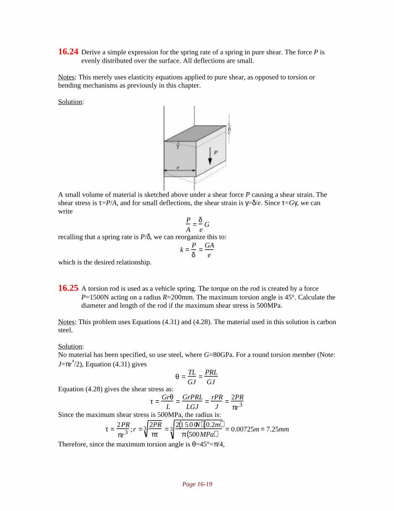
Page 16-19
16.24 Derive a simple expression for the spring rate of a spring in pure shear. The force P isevenly distributed over the surface. All deflections are small.
Notes: This merely uses elasticity equations applied to pure shear, as opposed to torsion orbending mechanisms as previously in this chapter.
Solution:
A small volume of material is sketched above under a shear force P causing a shear strain. Theshear stress is τ=P/A, and for small deflections, the shear strain is γ=δ/e. Since τ=Gγ, we canwrite
PA
= δe
G
recalling that a spring rate is P/δ, we can reorganize this to:
k = Pδ
= GAe
which is the desired relationship.
16.25 A torsion rod is used as a vehicle spring. The torque on the rod is created by a forceP=1500N acting on a radius R=200mm. The maximum torsion angle is 45°. Calculate thediameter and length of the rod if the maximum shear stress is 500MPa.
Notes: This problem uses Equations (4.31) and (4.28). The material used in this solution is carbonsteel.
Solution:No material has been specified, so use steel, where G=80GPa. For a round torsion member (Note:J=πr
4/2), Equation (4.31) gives
θ = TLGJ
= PRLGJ
Equation (4.28) gives the shear stress as:
τ = GrθL
= GrPRLLGJ
= rPRJ
= 2PR
πr3
Since the maximum shear stress is 500MPa, the radius is:
τ = 2PR
πr3 ;r = 2PRπτ
3 = 2 1 5 0 0N( ) 0.2m( )π 500MPa( )
3 = 0.00725m = 7.25mm
Therefore, since the maximum torsion angle is θ=45°=π/4,
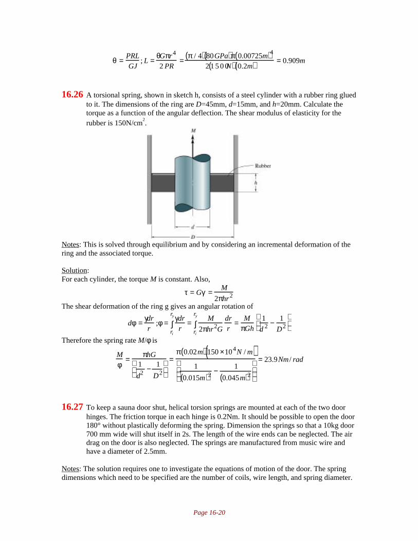
Page 16-20
θ = PRLGJ
; L = θGπr4
2 PR= π / 4( ) 80GPa( )π 0.00725m( )4
2 1 5 0 0N( ) 0.2m( ) = 0.909m
16.26 A torsional spring, shown in sketch h, consists of a steel cylinder with a rubber ring gluedto it. The dimensions of the ring are D=45mm, d=15mm, and h=20mm. Calculate thetorque as a function of the angular deflection. The shear modulus of elasticity for therubber is 150N/cm
2.
Notes: This is solved through equilibrium and by considering an incremental deformation of thering and the associated torque.
Solution:For each cylinder, the torque M is constant. Also,
τ = Gγ = M
2πhr2
The shear deformation of the ring g gives an angular rotation of
dφ = γdrr
;φ = γdrrri
ry
∫ = M
2πhr2G
drrri
ry
∫ = MπGh
1
d 2 − 1
D2
Therefore the spring rate M/φ is
Mφ
= πhG1
d2 − 1
D2
=π 0.02m( ) 150 ×104N / m( )
1
0.015m( )2 − 1
0.045m( )2
= 23.9Nm / rad
16.27 To keep a sauna door shut, helical torsion springs are mounted at each of the two doorhinges. The friction torque in each hinge is 0.2Nm. It should be possible to open the door180° without plastically deforming the spring. Dimension the springs so that a 10kg door700 mm wide will shut itself in 2s. The length of the wire ends can be neglected. The airdrag on the door is also neglected. The springs are manufactured from music wire andhave a diameter of 2.5mm.
Notes: The solution requires one to investigate the equations of motion of the door. The springdimensions which need to be specified are the number of coils, wire length, and spring diameter.

Page 16-21
Solution:The motion of the door is governed by
M − M f = −J ˙ ̇ φ where M is the moment of the spring, Mf is the friction moment, J is the door inertia and φ is theangular position of the door. Using Equation (16.42), M can be expressed as
M = M0 + EIlw
φ
where M0 is the prestress moment. Substituting this into the equation of motion gives
M0 − M f +EI
lwφ = −J ˙ ̇ φ ; ˙ ̇ φ +
EI
Jlwφ +
−M0 + M f
J= 0
This differential equation has the solution
φ = φ0 cosω t + lwEI
−M0 + M f( )where ω is given by
ω = EIJlw
Note that with this solution for φ,˙ ̇ φ = −ω2φ0 cosωt
M0 should be chosen to be as small as possible to close the door from any position, so that M0=Mf.The prestress angle for the spring is
φpEI
lw= M f = 0.2Nm; φp =
M f lwEI
In two seconds, the door should have shut if at time t=0 the door is fully open. Therefore at t=t0,φ=φ0, at t=2s, φ=φ0cos2ω=0. This requires that cos2ω=0 or that ω=π/4rad/s. Substituting in theexpression for ω,
ω = EIJlw
= π4
; lw = 16EI
π2 J=
16 207GPa( ) π 0.00125m( )4 / 4( )π2 0 . 5 1 0kg( ) 0.7m( )2
3
= 0.7878m
For half the door, since there are two hinges, At t=0, φ=φ0+π, or
φ =M f lw
EI+ π = 0.2Nm( ) 0.7878 m( )
207GPa( ) π 0.00125m( )4 / 4( ) + π = 3.539rad = 202.7°
The maximum bending moment in the spring wire is
Mmax = M0 + EIlw
φmax = 0.2Nm +207GPa( ) π 0.00125m( )4 / 4( )
0.7878m3.539rad( ) =1.983Nm
If C=10, Equation (16.41) gives
Ki =4C2 − C − 1
4C C − 1( )=
400 − 10 −1
40 9( )= 1.08
So that from Equation (16.40), the bending stress is
σ = 32K iM
πd3 = 32 1.08( ) 1.983 Nm( )π 0.0025m( )3 = 1397MPa
From Table 16.2, Ap=2170MPa and m=0.146, so that from Equation (16.2),
Sut = A
dm = 2170MPa
2.5( )0.146 = 1898MPa

Page 16-22
so that the safety factor is ns=1898/1397=1.359. The number of coils in the spring is
Na = lwπD
= 0.7878mπ 10( ) 0.0025m( ) =10.03
16.28 A helical torsion spring used in a door handle is made of hard-drawn steel wire with adiameter of 3mm. The spring has 10 active coils and a coil diameter of 21mm. After 5years of use the spring cracks due to fatigue. To get longer fatigue life, the stresses shouldbe decreased by 5%, but the only available cylindrical space is used by the present spring,which has an outside diameter of 24mm, an inside diameter of 18mm, and a length of30mm. The spring rate for the new spring would be the same as the old one. Find asolution.
Notes: There are numerous possibilities, such as choosing a new material or changing the crosssection. Note however that a new material would not be able to reduce the stresses, but a newmaterial may still be acceptable if its fatigue life is superior. This solution uses a rectangular crosssection to achieve the new spring design.
Solution:Note that for this spring, d=3mm. The spring rate needs to be the same, so from Equation (16.42),
Mθ
= EIlw
Also, Equation (16.40) gives the stress, which must be reduced by 5%. If the spring has to take upthe same space, C is constant and Ki will not be changed. Since M is also constant, then c/I has todecrease by 5%. This will be achieved by changing the cross section from circular to rectangular.Therefore, while keeping the same dimensions so that the rectangle’s width is 3mm,
0.95( ) cI
circle= c
I
rect; 0.95( ) d / 2
π64
d4
= h / 2
bh3 / 1 2( ) ;h = 2.36mm
So that the new spring will be of rectangular cross section with the same inner and outer diameter,but the cross section will be of width 3mm and height 2.36mm.
16.29 The oven door on a kitchen stove is kept shut by a helical torsion spring. The springtorque is 1Nm when the door is shut. When the oven door is fully open, it must stay openby gravitational force. The door height is 450mm and it weighs 4kg. Dimension thehelical torsion spring using music wire as the spring material and a wire diameter of4.5mm. Is it also possible to use 3mm wire?
Notes: This is an open ended problem in that one can use any reasonable combination of outerdiameter and number of coils can be used to get an answer. This solution uses C=D/d=10.Equation (16.42) is used in this problem.
Solution:This is an open-ended problem in that any reasonable value of D/d will give a good answer. Thissolution will be based on D/d=10. Recognizing that there needs to be a 1Nm moment at the doorclosed state, the torsion springs needs to be prewound a certain angular deflection θ. At θ+π/2(door open state), then the spring has to just barely support the door weight, which if uniformly

Page 16-23
distributed leads to a moment of M=(4kg)(0.450m/2)(9.81m/s2)=8.83Nm. We then have twoconditions, which allow us to write Eq. 16.42 twice:
θ = MlwEI
= 1Nm( )lwEI
;lwEI
= θ1Nm
θ + π2
= MlwEI
= (8.83Nm)lwEI
Substituting for lw/EI in the second equation gives θ=0.20rad=11.5°. This is the minimum angulardeflection from the free state, and in practice may be more than this so that the door stays openand requires a certain force to close. However, the design analysis will progress using this value.If d=0.0045m, then Equation (16.42) can be solved for the wire length:
θ = MlwEI
; lw = θEIM
=0.20rad( ) 207GPa( ) π
640.0045m( )4
1Nm= 0.83m
The number of turns needed is obtained from this wire length:
lw = πDNa; Na = lwπD
= 0.83mπ 0.045m( ) = 5.89
If d=0.003m, so that D=0.03m, then Equation (16.42) can be solved for the wire length:
θ =MlwEI
; lw =θEI
M=
0.20rad( ) 207GPa( ) π64
0.003m( )4
1Nm= 0.165m
The number of turns needed is obtained from this wire length:
lw = πDNa; Na =lwπD
=0.165m
π 0.03m( )=1.74
16.30 A helical torsion spring, shown in sketch i, is made from hard-drawn steel with a wirediameter of 2.2 mm and 8.5 turns. Dimensions are in millimeters.a) Using a safety factor of 2, find the maximum force and the corresponding angulardisplacement.b) What would the coil inside diameter be when the maximum load is applied?c) For 100,000 loading cycles calculate the maximum moment and the correspondingangular displacement for a safety factor of 2.5 guarding against fatigue failure.
Notes: The force is obtained from Equation (16.40) after the allowable stress in the wire isdetermined. The angular displacement is calculated from Equation (16.43) once the number ofactive coils is found from Equation (16.45). The inside diameter under maximum load is obtainedfrom Equation (16.46). The fatigue strength of the wire is calculated from Equations (7.9)through (7.13), although the Zimmerli equations (16.29) could alternatively be used.
Solution:
Page 16-24
From Table 16.1, for hard drawn wire, G=11.5Mpsi=79.3GPa, and take E=207GPa as for carbonsteel from the inside front cover. From Table 16.2 for hard drawn wire, Ap=1750MPa, m=0.192.Therefore, the ultimate strength of the wire is obtained from Equation (16.2) as:
Sut =Ap
d m = 1750MPa
2.20.192 = 1505MPa
The allowable shear stress is calculated from Equations (16.3)as:Ssy = σall = 0.6Sut = 0.6 1505MPa( ) = 903MPa
Also, for this spring, from Equation (16.6), C=D/d=22mm/2.2mm=10, so from Equation (16.41),
Ki = 4C2 − C −14C C −1( ) = 400 −10 −1
40 9( ) = 1.08
Recognizing that M=P(0.035m), Equation (16.40) gives
σ =Sy
ns=
32K iP 0.035m( )πd3 ; P =
Syπd3
32ns Ki 0.035m( )=
903MPa( )π 0.0022m( )332 2( ) 1.08( ) 0.035m( )
= 12.5N
From Equation (16.45) on page 762,
Na = Nb + Ne = Nb + l1 + l23πD
= 8.5+ 0.035m + 0.035m3π 0.022m( ) = 8.84
So that from Equation (16.43),
θrev =10.18MDNa
Ed4 =10.18 12.5N( ) 0.035m( ) 0.022 m( ) 8.84( )
207GPa( ) 0.0022m( )4= 0.18
Therefore, under the maximum load, the number of coils is Na’=Na+θrev=8.84+0.18=9.02. From
Equation (16.46),
Di′ =
Na Di
Na′ =
8.84 0.0198m( )9.02
= 0.0194m
Note from Equation (7.7) that for bending, Se’=0.5Su=0.5(1505MPa)=753MPa. From Equation
(7.8), Sl’=0.9Su=0.9(1505MPa)=1355MPa. From Equation (7.12),
bs = −13
logSl
′
Se′
= − 1
3log
0.9Sut
0.5Sut
= −0.085
From Equation (7.13),
C = logSl
′( )2
Se′
= log13552
753
= 3.387
Therefore, the fatigue strength is, from Equation (7.14) on page 269,
S f′ = 10C Nt
′( )bs=103.387 100000( )−0.085 = 916MPa
For this spring, σmin=0, σmax=σ, so σm=σa=σ/2. Using a Goodman relationship (see Equation(7.28)),
σa
S f′ + σm
Sut= σ
2 916MPa( ) + σ2 1505MPa( ) = 1
ns= 1
2.5;σ = 455MPa
Therefore, from Equation (16.40), the maximum force is
σ = 32K iP 0.035m( )πd3 ; P = σπd3
32Ki 0.035m( ) = 455MPa( )π 0.0022m( )3
32 1.08( ) 0.035m( ) =12.6 N
Therefore, Mmax=P(0.035m)=12.6N(0.035m)=0.441Nm. The corresponding angular displacementis, from Equation (16.43),

Page 16-25
θrev = 10.18 MDNa
Ed4 = 10.18 0.44Nm( ) 0.022m( ) 8.84( )207GPa( ) 0.0022m( )4 = 0.180rev
16.31 The helical torsion spring shown in sketch j has a coil outside diameter of 22mm, 8.25turns, and a wire diameter of 2 mm. The spring material is hard-drawn steel. What wouldthe applied moment be if the maximum stress equaled the yield limit? Calculate theinside diameter of the loaded spring and the corresponding angular displacement.Dimensions are in millimeters.
Notes: This is similar to the first part of problem 16.30. Equations (16.2) and (16.3) are needed toget the strength of the wire. Equation (16.40) is used to get the normal stress, and Equation(16.43) gives the angular deflection.
Solution:From Table 16.1, for hard drawn wire, G=11.5Mpsi=79.3GPa, and take E=207GPa as for carbonsteel from the inside front cover. From Table 16.2 for hard drawn wire, Ap=1750MPa, m=0.192.Therefore, the ultimate strength of the wire is obtained from Equation (16.2) as:
Sut =Ap
d m = 1750MPa
20.191 = 1532MPa
The yield stress in tension is approximately given by Equation (16.39):Sy =0.6Sut = 0.6 1532MPa( ) = 919MPa
For this spring, D=D0-d=22mm-2mm=20mm=0.020m. From Equation (16.6),C=D/d=20mm/2mm=10. Therefore, from Equation (16.41),
Ki = 4C2 − C −14C C −1( ) = 400 −10 −1
40 9( ) = 1.08
The normal stress is given by Equation (16.40) and set equal to the yield strength, and solved forthe applied moment as follows:
σ = 32K iM
πd3 = Sy ;M =Syπd3
32Ki= 919MPa( )π 0.002m( )3
32 1.08( ) = 0.668Nm
The angular deflection in revolutions is given by Equation (16.43) as
θrev = 10.18MDNa
Ed4 = 10.18 0.668Nm( ) 0.020m( ) 8.25( )207GPa( ) 0.002m( )4 = 0.339
The new number of active coils is given by Equation (16.45) asNa
’=Na+θrev=8.25+0.339=8.589Therefore, from Equation (16.46), the new inner diameter is
Di′ = Na Di
Na′ = 8.25( ) 20mm − 2mm( )
8.589( ) = 17.29mm

Page 16-26
16.32 A helical torsion spring made of music wire has a coil diameter of 17.5mm and a wirediameter of 1.5mm while supporting a 0.15Nm moment with 20% fluctuation. Themaximum number of turns is 12, and the load is 22 mm from the center of the spring. Forinfinite life with 99% reliability, find the safety factors guarding against static and fatiguefailure. Also, determine the inside diameter of the spring when the load has been applied.
Notes: The wire strength is determined as in the previous problems. A mean and alternatingmoment is calculated, which allows calculation of mean and alternating stresses. A Goodmanrelationship is then used for fatigue.
Solution:From Table 16.1, for music wire, G=11.5Mpsi=79.3GPa, and take E=207GPa as for carbon steelfrom the inside front cover. From Table 16.2 for music wire, Ap=2170MPa, m=0.146. Therefore,the ultimate strength of the wire is obtained from Equation (16.2) as:
Sut =Ap
d m = 2170MPa
1.50.146 = 2045MPa
From Equation (7.7) on page 265, Se’=0.5Sut=0.5(2045)=1022MPa. If the wire is drawn, from
Table 7.3, e=4.51 and f=-0.265, so kf is from Equation (7.21):
k f = eSutf = 4.511022( )−0.265 = 0.72
From Table 7.2, kr=0.82 for 99% reliability. The size factor is, from Equation (7.22), ks=1.Therefore, from Equation (7.16),
Se=kfkskrSe’=(0.72)(0.82)(1)(1022MPa)=603MPa
The maximum moment is Mmax=1.2(0.15Nm)=0.18Nm. The minimum moment isMmin=0.8(0.l5Nm)=0.12Nm. Therefore, Ma=(Mmax-Mmin)/2=0.03Nm, and Mm=0.15Nm. For thisspring, C=D/d=17.5/1.5=11.67. Therefore, from Equation (16.41),
Ki = 4C2 − C −14C C −1( ) = 4 11.67( ) −11.67 −1
4 11.67( ) 10.67( ) = 1.07
From Equation (16.40), the alternating stress is:
σa = 32Ki Ma
πd3 = 32 1.07( ) 0.03Nm( )π 0.0015m( )3
= 96.9MPa
Similarly the mean stress is:
σm = 32Ki Mm
πd 3 = 32 1.07( ) 0.15Nm( )π 0.0015m( )3
= 484.4MPa
The static safety factor is
ns = Sut
σ max= Sut
σ a +σ m= 2045MPa
96.9MPa + 484.4MPa= 3.52
The safety factor against fatigue is calculated using a Goodman relationship (Equation (7.28)):1ns
= σa
Se+ σm
Sut= 96.9MPa
603MPa+ 484.4MPa
2045MPa= 0.398; ns = 2.51
16.33 A fishing rod is made like an ideal leaf spring with rectangular cross sections. It is madeof carbon-fiber reinforced plastic with a 150GPa modulus of elasticity. The thickness isconstant at 8mm and the length is 2m. Find how large the cross section must be at the

Page 16-27
handle to carry a 0.3 kg fish by the hook without bending the top of the rod more than200mm. Neglect the weight of the lure. Also, calculate the bending stress.
Notes: Equation (16.51) is needed to obtain the width. Equation (16.49) gives the stress.
Solution:The load is P=(0.3kg)(9.81m/s
2)=2.94N. From Equation (16.51), with d=0.2m and n=1,
δ = 6Pl3
Enbt3;b = 6Pl3
Enδt3 = 6 2.94N( ) 2m( )3
150GPa( ) 1( ) 0.2m( ) 0.008m( )3= 0.00919m = 9.19mm
The stress is obtained from Equation (16.49) as
σ = 6Pl
bt2 = 6 2.94N( ) 2m( )0.00919m( ) 0.008m( )2 = 60.0MPa
16.34 A trampoline is made like a leaf spring with variable width so that the maximum bendingstress in each section of the trampoline is constant. The material is glass-fiber reinforcedplastic with a modulus of elasticity of 28GPa and a bending strength of 300MPa.Calculate the spring rate at the tip of the trampoline and the corresponding safety factor ifa swimmer weighing 80kg jumps onto the trampoline from a height of 2 m. The activelength of the trampoline is 3m, its width is 1.2 m, and its thickness is 38mm.
Notes: The change in potential energy equals the energy stored in bending, and this allowscalculation of the deflection. Using Equation (16.52) gives the stiffness of the spring, so theapplied force can be calculated from the deflection. Equation (16.49) then gives the stress.
Solution:The stiffness of the spring is calculated from Equation (16.52) using n=1:
k = Enbt3
6l3= 28GPa( ) 1( ) 1.2m( ) 0.038m( )3
6 3m( )3 = 11.38kN / m
From the first law of thermodynamics, the energy stored in the spring must be the same as thechange in potential energy of the swimmer. Therefore,
mag h + δ( ) = kδ2
2; δ 2 − 2mag
kδ − 2magh
k= 0; δ = 2mag
2k± 1
22mag
k
2
+ 42magh
k
substituting ma=80kg, g=9.81m/s2, h=2m and k=11.38kN/m gives δ=0.5987m. Therefore, the
maximum force is P=kδ=(11.38kN/m)(0.5987m)=6.81kN. Therefore, from Equation (16.49), thestress is
σmax = 6Pl
bt2= 6 6810N( ) 3m( )
1.2m( ) 0.038m( )2 = 70.7MPa
Therefore, the safety factor is ns=300MPa/70.7MPa=4.24
16.35 The leaf spring of a truck should be able to accommodate 55 mm deflections (up anddown) of the wheels from an equilibrium position when the truck is driven on a roughroad. The static load in the middle of the leaf spring is 50,000N. The modulus ofelasticity for the spring is 207GPa.Assume an allowable stress of 1050 MPa, a safetyfactor of 3, leaf length of 0.8 m, a thickness of 0.02 m, and that they are split into 10layers. Determine the width of the spring.

Page 16-28
Notes: Equation (16.49) gives the stress in the spring, which gives an equation for the springwidth. The deflection is calculated from Equation (16.52).
Solution:With a safety factor of 3, the allowable stress is Using Equation (16.49) to obtain the maximumstress,
σmax =6Pl
bt2=
σall
3;b =
18Pl
σallt2 =
18( ) 50,000 N( ) 0.8m( )1050MPa( ) 0.02m( )2 = 1.714m
From Equation (16.52), the deflection is
δ =6Pl3
Enbt3=
6 50 ,000N( ) 0.8 m( )3
207GPa( ) 10( ) 1.714 m( ) 0.02 m( )3 = 0.0512m = 54.12mm

Page 17-1
Chapter 17 • Brakes and Clutches
17.1 The disk brake shown in sketch a has brake pads in the form of circular sections withinner radius r, outer radius 2r, and section angle π/4. Calculate the brake torque when thepads are applied with normal force P. The brake is worn in so pu is constant, where p isthe contact pressure and u is the sliding velocity. The coefficient of friction is µ.
Notes: If pu is constant, and u=rω, then this gives a relationship for pressure in terms of radius.This relation is then substituted into Equation (17.2) and to eliminate the unknown constant, andinto Equation (17.3) to get an expression for torque.
Solution:Since pu is constant and u=rω, then we can deduce that p=C/rω, where C is a constant.Substituting into Equation (17.2), and noting that the section angle is π/4,
dP = prdθdr = Crω
rdθdr = Cω
dθdr; P = Cω
drdθ
r
2r
∫0
π / 4
∫ = Cπr4ω
;C = 4ωPπr
Note that the torque is generated on both sides of the rotor. Therefore, the torque is obtained fromEquation (17.3) as
T = 2 µpr2drdθ = 2 µ C
rω
r2drdθ = 2µC
ωrdrdθ = 2µC
ωπ4
1
22r( )2 − 1
2r2
= 3πµCr 2
4ω∫∫∫∫∫∫Substituting for C gives T=3µrP.
17.2 An automotive clutch with a single friction surface is to be designed with a maximumtorque of 140Nm. The materials are chosen such that µ=0.35 and pmax=0.35 MPa. Usesafety factor ns=1.3 with respect to slippage at full engine torque and as small an outsidediameter as possible, determine appropriate values of ro, ri and P by using both theuniform pressure and uniform wear models.
Notes: The approach is the same as in Example 17.1 on page 787; an equation is obtained forouter radius in terms of inner radius. Taking the derivative and solving for the optimum gives theanswer. Equations (17.5) and (17.12) are used for the torque for the two wear models.
Solution:I. Uniform Pressure ModelFrom Equation (17.5), and using the safety factor prescribed, the torque is given by

Page 17-2
nsTp = 2πµp0
3ro
3 − ri3( );ro =
3nsTp
2πµp0+ ri
3
1 / 3
= 3 1.3( ) 140Nm( )2π 0.35( ) 0.35MPa( ) + ri
3
1 / 3
= 7.09 ×10⁻⁴ m3 + ri3( )1 / 3
Taking deravitive with respect to ri, setting equal to zero and solving for ri gives:∂ro∂ri
= ∂∂r
7.09 ×10⁻⁴m3 + ri3( )1 / 3
= 13
7.09 ×10⁻⁴m3 + ri3( )−2 / 3
3ri2( ) = 0; ri = 0
Therefore, the outer radius is 0.08917m. From Equation (17.4), the actuating force is
Pp = πp0 ro2 − ri
2( ) = π 0.35MPa( ) 0.08917 m( )2 − 02[ ]= 8743N
II. Uniform Wear ModelFrom Equation (17.12), and using the safety factor gives
nsTw = πµri pmax ro2 − ri
2( )ro = nsTw
πµri pmax+ ri
2
1 / 2
= 1.3( ) 140Nm( )π 0.35( ) 0.35MPa( )
1
ri+ ri
2
1 / 2
= 4.73 ×10⁻⁴ m3 1
ri+ ri
2
1 / 2
Taking derivative with respect to ri as before, setting equal to zero and solving for ri gives:
∂ro∂ri
= 12
4.73 ×10⁻⁴m3 1ri
+ ri2
−1 / 2
−4.73 ×10⁻⁴ m3 1
ri2 + 2ri
= 0
Solving this numerically gives ri=0.0618m, so that ro=0.107m. From Equation (17.13), themaximum actuating force is (remember to use the safety factor)
nsTw =µPw ro + ri( )
2;Pw = 2nsTw
µ ro + ri( ) = 2 1 . 3( ) 140 Nm( )0.35( ) 0.107 m + 0.0618m( ) = 6160N
17.3 The brakes used to stop and turn a tank are built like a multiple disk clutch with threeloose disks connected through splines to the drive shaft and four flat rings connected tothe frame of the tank. The brake has an outer contact diameter of 600mm, an innercontact diameter of 300mm, and six contact surfaces. The coefficient of friction of thebrake is 0.12, and the friction between the caterpillar and the ground is 0.16, which givesa braking torque of 12,800 Nm to block one caterpillar track so that it slides along theground. Calculate the force needed to press the brake disks together to block onecaterpillar track. Also calculate the force when the brake is new.
Notes: When new, the brakes are better characterized by the uniform pressure model of Equation(17.5). After the brakes are in service, however, the brake is better modeled through Equation(17.13) of the uniform wear model.
Solution:Note that there are six contact surfaces. Therefore, the torque per contact surface is 12,800Nm/6=2133Nm. From the uniform wear model, the force needed can be calculated from Equation(17.13) as:
Tw =µPw ro + ri( )
2; Pw = 2Tw
µ ro + ri( ) = 2 2133Nm( )0.12( ) 0.3m + 0.15m( ) = 79kN
For new brakes, the uniform pressure model is better, so Equation (17.5) gives
Tp =2µPp ro
3 − ri3( )
3 ro2 − ri
2( ) ; Pp =3Tp ro
2 − ri2( )
2µ ro3 −ri
3( ) =3 2133Nm( ) 0.3m( )2 − 0.15m( )2( )
2 0.12( ) 0.3m( )3 − 0.15m( )3( ) = 76.2kN

Page 17-3
17.4 A disk brake used in a printing machine is designed as shown in sketch b. The brake padis mounted on an arm that can swivel around point O. Calculate the braking torque whenthe force P=5000N. The friction pad is a circular cross section with the inner radius equalto half the outer radius. Also, a=150mm, b=50mm, D=300mm, and µ=0.25. The wear ofthe brake lining is proportional to the pressure and the sliding distance.
Notes: One equation relates the wear to the product of pressure and sliding distance, anotherrelates wear to the angular rotation. This allows for the pressure to be determined as a function ofφ.
Solution:Since the wear is proportional to the pressure and the sliding distance (which is l=rωt), the wearvolume at some radius r can be written as
dV=C1prωtdAAlso, from the geometry,
dV=C2rcosφTherefore, equating dV/dA gives
dVdA
= C1prωt = C2r cosφ ; p = C2
C1ωtcosφ = C3 cosφ
Note that we have taken ω and t as constants because they do not rely on radius or angularposition. From Equation (17.3), the torque is
T = prdφdrµr
ri
ro
∫ = C3µ r2dr
ri
ro
∫ cos φdφ
−α /2
α / 2
∫ = 23
C3µ ro3 − ri
3( )sinα2
The actuating moment is
Pa = prdφdrr cosφ = C3
6ro
3 − ri3( ) α + sinα( )
−α / 2
α /2
∫ri
ro
∫Substituting into the torque expression gives
T = 4µPasin
α2
α + sinα( ) = 4 0.25( ) 5000N( ) 0.15m( ) sin30°π3
+ s i n 6 0°
=196Nm

Page 17-4
17.5 A disk brake for a flywheel is designed as shown in sketch c. The hydraulic pistonsactuating the brake need to be placed at a radius rp so that the brake pads wear evenlyover the entire contact surface. Calculate the actuating force P and the radius so that theflywheel can be stopped within 4s when it rotates at 1000rpm and has a kinetic energy of5 x 10
5 Nm. The input parameters are µ=0.3, α=30°, ro=120mm, ri=60mm.
Notes: This is solved with the uniform wear model, so that equation (17.7) gives an expressionbetween pressure and radius. Equations (17.2) and (17.3) are then used to obtain a solution.
Solution:First of all, ω=1000rpm=104.7rad/s. From Equation (17.7), p=C/r so C=pr. Therefore, fromEquation (17.2),
P = prdθdr
0
α
∫ri
ro
∫ = Cdθdr
0
α
∫ri
ro
∫ = Cα ro − ri( )
Similarly, from Equation (17.3), noting that there are two friction surfaces,
T = 2 µpr2drdθ
ri
ro
∫0
α
∫ = µCα ro2 − ri
2( )Substituting into the expression for P gives:
P = Tµ ro + ri( )
The kinetic energy of a flywheel is from Equation (11.65), Ke=Jω2/2. The torque causes a
decelleration ofT=-Jdω/dt, or Tdt=-Jdω.
Integrating,
T dt
0
t
∫ = −J dω
ω m
0
∫ ;T = Jωm
t= Jω m
2
22
ω mt= Ke
2ω mt
Therefore

Page 17-5
T dt
0
t
∫ = −J dω
ω m
0
∫ ;T = Jωm
t= Jω m
2
22
ω mt= Ke
2ω mt
= 5×10⁵ Nm( ) 2104.7rad / s( ) 4s( ) = 2390Nm
Therefore, the actuating force is
P = Tµ ro + ri( ) = 2390Nm
0.3( ) 0.12m + 0.06m( ) = 44.3kN
To calculate the position rp, note that
rpP = prdφdrr cosφ
−α / 2
α /2
∫ri
ro
∫ = C ro2 − ri
2( ) sinα2
Since P=Cα(ro-ri),
rp =C ro
2 − ri2( )sin
α2
Cα ro − ri( ) =ro + ri( )sin
α2
α= 0.12m + 0.06m( )sin15°
π / 6= 0.089m
17.6 Three pairs of thrust disk clutches are mounted on a shaft. Each has a pair of frictionalsurfaces. The hardened-steel clutches are identical, with an inside diameter of 100 mmand an outside diameter of 245mm. What is the torque capacity of these clutches basedon a) uniform wear and b) uniform pressure?
Notes: This problem is straightforward and is similar to Problem 17.3. However, one must obtaindata for the contacting materials from Table 17.1 on page 787.
Solution:From Table 17.1 on page 787, for hard steel µ is between 0.15 and 0.25, so we take µ=0.2 as anaverage value. Also from Table 17.1, pmax is between 690 and 1720kPa, so take pmax=1200kPa.There are six friction surfaces. Therefore, for the uniform wear model, the torque is given byEquation (17.12) as
Tw = 6πµripmax ro2 − ri
2( ) = 6π 0.2( ) 0.05 m( ) 1200kPa( ) 0.1225m( )2 − 0.05 m( )2( ) = 2839Nm
For the uniform pressure model, Equation (17.5) gives
Tp = 62πµp0
3ro
3 − ri3( ) = 12π 0.2( ) 1200kPa( )
30.1225m( )3 − 0.005m( )3( ) = 5167Nm
17.7 A pair of disk clutches has an inside diameter of 250mm and an outside diameter of 420mm. A normal force if 18.5kN is applied and the coefficient of friction of the contactingsurfaces is 0.215. Using the uniform wear and uniform pressure assumptions determinethe maximum pressure acting on the clutches. Which of these assumptions wouldproduce results closer to reality?
Notes: Equations (17.4) and (17.10) are needed to solve this problem. Two clutches can bearranged so that each takes the full applied load or that each takes one-half the load. This solutionconsiders the case when each clutch sees the applied load.
Solution:For the uniform pressure model, Equation (17.4) gives

Page 17-6
Pp = πp0 ro2 − ri
2( ); p0 =Pp
π ro2 − ri
2( ) = 18.5kN
π 0.21m( )2 − 0.125m( )2( ) = 206.8kPa
For the uniform wear model, Equation (17.10) gives
Pw = 2πpmaxri ro − ri( ); pmax = Pw
2πri ro − ri( ) = 18,500 N2π 0.125m( ) 0.21m − 0.125m( ) = 277kPa
17.8 A disk clutch is made of cast iron and has a maximum torque of 210 Nm. Because ofspace limitations the outside diameter must be minimized. Using the uniform wearassumption and a safety factor of 1.3, determinea) The inner and outer radii of the clutchb) The maximum actuating force needed.
Notes: The approach is the same as in Example 17.1 on page 787; an equation is obtained forouter radius in terms of inner radius. Taking the derivative and solving for the optimum gives theanswer. Equation (17.12) is used for the torque. Table 17.1 is used to get the friction coefficientand the maximum pressure.
Solution:From Table 17.1 for cast iron, an average value of friction coefficient is 0.20. The low range ofpressure is 690kPa. Equation (17.12) gives the torque as (note the inclusion of the safety factor):
Tw = πµripmax
nsro
2 − ri2( )
ro = nsTwπµri pmax
+ ri2
1 / 2
= 1.3( ) 210 Nm( )π 0.2( ) ri( ) 690kPa( )
+ ri2
1 / 2
= 6.30 ×10⁻⁴ m3 1ri
+ ri2
1 / 2
Taking derivative with respect to ri, setting equal to zero and solving gives:
drodri
= 12
6.30 ×10⁻⁴m3 1ri
+ ri2
−1 / 2
−6.30 × 10⁻⁴ m3 1
ri2 + 2ri
= 0; ri = 0.068m
Therefore, ro=0.118m. Therefore, the maximum actuating force needed is, from Equation (17.10),
Pw = 2π pmax
nsri ro − ri( ) = 2π 690kPa( )
1.30.068m( ) 0.118m − 0.068m( ) =11.3kN
17.9 A disk clutch produces a torque of 125Nm and a maximum pressure of 315kPa. Thecoefficient of friction of the contacting surfaces is 0.28. Assuming a safety factor of 1.8for maximum pressure and design the smallest disk clutch for the above constraints. Whatshould the normal force be?
Notes: The approach is very similar to Problem 17.8.
Solution:Equation (17.12) gives the torque as (note the inclusion of the safety factor):

Page 17-7
Tw = πµripmax
nsro
2 − ri2( )
ro = nsTwπµri pmax
+ ri2
1 / 2
= 1.8( ) 125 Nm( )π 0.28( ) ri( ) 315kPa( )
+ ri2
1 / 2
= 8.12 ×10⁻⁴ m3 1ri
+ ri2
1 / 2
Taking derivative with respect to ri, setting equal to zero and solving gives:
drodri
= 12
8.12 ×10⁻⁴m3 1ri
+ ri2
−1 / 2
−8.12 ×10⁻⁴ m3 1
ri2 + 2ri
= 0;ri = 0.074m
Therefore, ro=0.128m. Therefore, the maximum actuating force needed is, from Equation (17.10),
Pw = 2π pmax
nsri ro − ri( ) = 2π 315kPa( )
1.80.074m( ) 0.128m − 0.074m( ) = 4.39kN
17.10 A leather-face cone clutch is to transmit 1200lbf-in of torque. The half-cone angle α=10°,the mean diameter of the friction surface is 12in, and face width b=2in. For coefficient offriction µ=0.25 find the normal force P and the maximum contact pressure p by usingboth the uniform pressure and uniform wear models.
Notes: Equations (17.23) and (17.21) are used for the uniform pressure model. Equations (17.26)and (17.24) are used for the uniform pressure model. The diameters have to be determined asdefined in Figure 17.4.
Solution:The mean diameter is given as 12 inches. Referring to Figure 17.4 on page 789, it can be seen that
D = dave + 2b2
tan α
= 12in + 2 in( ) tan10° =12.35in
d = dave − 2b2
tan α
= 12in − 2 in( ) tan10° =11.65in
For the uniform pressure model, Equation (17.23) gives
T =µW D3 − d3( )
3sinα D2 − d2( ) ;W =3T sinα D2 − d2( )
µ D3 − d3( ) =3 1 2 0 0inlb( )sin10° 12.35in( )2 − 11.65in( )2( )
0.25( ) 12.35in( )3 − 11.65 in( )3( ) = 139lb
Therefore, from Equation (17.21),
W = πp0
4D2 − d2( ); p0 = 4W
π D2 − d2( ) = 4 1 3 9lb( )π 12.35in( )2 − 11.65in( )2( ) =10.5psi
For the uniform wear model, Equation (17.26) gives
T = µW4 s i nα
D + d( );W = 4T sinαµ D + d( ) = 4 1 2 0 0inlb( )sin10°
0.25( ) 12.35in + 11.65 in( ) =140lb
Note from Equation (17.9) that c=pmaxri=pmaxd/2. Therefore, from Equation (17.24),
W = πc D − d( )= π pmax( ) d2
D− d( ); pmax = 2Wπd D − d( ) = 2 140 lb( )
π 11.65in( ) 12.35 in− 11.65in( ) =10.9 psi
17.11 The synchronization clutch for the second gear of a car has a major cone diameter of50mm and a minor diameter of 40mm. When the stick shift is moved to second gear, thesynchronization clutch is engaged with an axial force of 100N, and the moment of inertia

Page 17-8
of 0.005kg-m2 is accelerated 200rad/s
2 in 1s to make it possible to engage the gear. The
coefficient of friction of the cone clutch is 0.09. Determine the smallest cone clutch widththat still gives large enough torque. Assume the clutches are worn in.
Notes: Since the clutch is worn in, we can use the uniform wear model. Equation (17.26) will beused to determine α, which then allows one to calculate b.
Solution:Note that the torque is the product of the moment of inertia and angular acceleration, so that
T=(0.005kgm2)(200rad/s
2)=1Nm
From Equation (17.26),
T = µW4 s i nα
D + d( );sinα = µW4T
D+ d( ) = 0.09( ) 100N( )4 1Nm( ) 0.05m + 0.04m( ) = 0.2025
or α=11.68°. Therefore, from Figure 17.4,
tan α = D − d2b
;b = D − d2tan α
= 0.05m − 0.04m2tan11.68°
= 0.0242m = 24.2mm
17.12 A safety brake for an elevator is a self-locking cone clutch. The minor diameter is120mm, the width is 60 mm, and the major diameter is 130mm. The force applying thebrake comes from a prestressed spring. Calculate the spring force needed if the 2-tonelevator must stop from a speed of 3m/s in a maximum distance of 3m while the coneclutch rotates five revolutions per meter of elevator motion. The coefficient of friction inthe cone clutch is 0.26.
Notes: Using the sketch of Figure 17.4, the cone angle α must be derived. The torque is obtainedfrom the absorbed energy, and the spring force then follows from Equation (17.23). Note also thatsince the problem statement is in metric units, a ton will be taken as 1000 kg.
Solution:From Figure 17.4, the cone angle is obtained as:
tan α = D − d2b
= 130mm − 120mm( )2 60mm( ) = 0.08333; α = 4.764°
The energy which must be absorbed by the clutch is the product of the torque and angulardisplacement, and this equals the energy change in the elevator over the same interval. Theenergy change in the elevator is the sum of the kinetic and potential energies, so that
Tθ = 12
mav2 + ma gh;T =
12
mav2 + magh
θ=
12
2000kg( ) 3m / s( )2 + 2000kg( ) 9.81m / s2( ) 3m( )15rev 2πrad / rev( )
or T=720Nm. Therefore, from Equation (17.23),
T =µW D3 − d3( )
3sinα D2 − d2( ) ;W =3T sinα D2 − d2( )
µ D3 − d3( ) =3 720Nm( )sin 4.764° 0.13m( )2 − 0.12m( )2( )
0.26( ) 0.13m( )3 − 0.12m( )3( ) = 3678N
17.13 A cone clutch is used in a car automatic gearbox to fix the planet wheel carriers to thegearbox housing when the gear is reversing. The car weighs 1300kg with 53% loading onthe front wheels. The gear ratio from the driven front wheelsto the reversing clutch is

Page 17-9
16.3:1 (i.e., the torque on the clutch is 16.3 times lower than the torque on the wheels ifall friction losses are neglected). The car wheel diameter is 550mm, the cone clutch majordiameter is 85mm and the minor diameter is 80mm, and the coefficients of friction are0.3 in the clutch and 1.0 between the wheel and the ground. Dimension the width of thecone clutch so that it is not self-locking. Calculate the axial force needed when the clutchis worn in.
Notes: Statics on the cone gives a relationship for a cone angle which will disengage whendesired. The torque on the wheel is calculated for spinning tires (the worst case scenario), reducedby the gear ratio, and then Equation (17.26) or (17.23) will allow for determination of W.
Solution:The forces acting on the cone clutch are sketched above for when the inner cone is trying todisengage from the outer cone (thus the direction of the friction force). From horizontalequilibrium, if µNcosα is greater than Nsinα, then the inner cone can’t disengage from the outercone. This means:
N sinα > Nµcosα ; t anα > µ; α > tan−1 0.3 = 0.291rad =16.7°Note from Figure 17.4,
tan α = D − d2b
= 0.085m − 0.080m2b
= 0.0025mb
Combining the two relationships,0.0025m
b> 0.3;b < 0.025m
0.3= 0.0083m
As for the specification of these values, one must consider the likelihood of the frictioncoefficient becoming larger than 0.3, and if so, by how much. If we assume that this is already aworst case scenario, then these values can be used as a design solution, although from amanufacturing perspective it may be better practice to specify a 20° cone angle and b=6mm.However, let us continue the analysis using b=0.0083 and α=16.7°. The torque on the ground asthe front wheels spin (the maximum torque) is:
T = 1300kg( ) 9.81m / s2( ) 0.53( ) 0.550m2
1.0( ) = 1860Nm
The torque at the clutch, because of the gear reduction, is 1860/16.3=114Nm. Therefore, fromEquation (17.23), the axial force required can be found as:
T =µW D3 − d3( )
3sinα D2 − d2( ) ;W =3T sinα D2 − d2( )
µ D3 − d3( ) =3 1 1 4Nm( )s in16.7° 0.085m( )2 − 0.08m( )2( )
0.3( ) 0.085m( )3 − 0.08m( )3( ) = 2646N
while Equation (17.26) would predict
T = µW4 s i nα
D + d( );W = 4T sinαµ D + d( ) = 4 114Nm( )sin16.7°
0.3( ) 0.085m + 0.08m( ) = 2647N
Which is not significantly different from the results of Equation (17.23).
17.14 A cone clutch has a major diameter of 328mm and a minor diameter of 310 mm, is 50mm wide and transfers 250Nm of torque. The coefficient of friction is 0.31. Using theassumptions of uniform pressure and uniform wear, determine the actuating force and thecontact pressure.
Notes: The cone angle is found from Equation (17.4). Equations (17.21) and (17.23) are neededfor the uniform pressure model, Equations (17.24) and (17.26) for the uniform wear model.

Page 17-10
Solution:From Figure 17.4,
tan α = D − d2b
= 328mm − 310mm2 50mm( ) = 0.18; α = 10.2°
For the uniform pressure model, Equation (17.23) can be solved for the force as:
T =µW D3 − d3( )
3sinα D2 − d2( ) ;W =3T sinα D2 − d2( )
µ D3 − d3( ) =3 250Nm( )sin10.2° 0.328m( )2 − 0.310m( )2( )
0.31( ) 0.328m( )3 − 0.310m( )3( )or W=895N. The pressure is obtained from (17.21) as
W = πp0
4D2 − d2( ); p0 = 4W
π D2 − d2( ) = 4 895N( )π 0.328m( )2 − 0.31m( )2( ) = 99.3kPa
For the uniform wear model, Equation (17.26) gives
T = µW4 s i nα
D + d( ); W = 4T sinαµ D + d( ) = 4 250Nm( )sin10.2°
0.31( ) 0.328m + 0.30 m( ) = 896N
Therefore, noting from Equation (17.9) that c=pmaxri=pmaxd/2, the maximum pressure is obtainedfrom Equation (17.24) as
W = πpmaxd D − d( )2
; pmax = 2Wπd D − d( ) = 2 896N( )
π 0.30m( ) 0.318m − 0.30m( ) = 102kPa
17.15 The coefficient of friction of a cone clutch is 0.25. It can support a maximum pressure of410 kPa while transferring a maximum torque of 280Nm. The width of the clutch is65mm. Minimize the major diameter of the clutch. Determine the clutch dimension andthe actuating force.
Notes: The solution is obtained from Equations (17.25) and (17.9).
Solution:From Equation (17.9) note that c=pmaxri=pmaxd/2, so that Equation (17.25) gives:
T = πµpmaxd8sin α
D2 − d2( )Also, since from Figure 17.4,
tan α = D − d2b
; s i nα = D− d
2D − d
2
2+ b2
Substituting into the torque relation gives a complicated function of D and d. Note that at d=0, thetorque transmitted is zero since the maximum pressure is at the center and is infinite for a finitetorque transferred. Therefore, d must be greater than zero. A plot of the required D as a functionof d is shown below. The outer diameter is minimum as it approaches d, so that a approacheszero. Using D=d=0.164 is not practical to manufacture; use D=0.165m and d=0.163m just toillustrate that W in this case is 210N.

Page 17-11
17.16 A block brake is used to stop and hold a rope used to transport skiers from a valley to thetop of a mountain. The distance between cars used to transport the skiers is 100m, thelength of the rope from the valley to the top of the mountain is 4 km, and the altitudedifference is 1.4km. The rope is driven by a V-groove wheel with a diameter of 2m. Therope is stopped and held with a block brake mounted on the shaft of the V-groove wheel,shown in sketch d. Neglect all friction in the different parts of the ropeway except frictionin the driving sheave, and assume that the slope of the mountain is constant. Dimensionthe brake for 20 passengers with each passenger’s equipment weighing 100 kg, andassume that all ropeway cars descending from the top are empty of people. The directionof rotation for the drive motor is shown in the figure. Calculate the braking force Wneeded to hold the ropeway still if all passengers are on the way up. Do the samecalculation if all passengers continue on down to the valley with the ropeway. Thecoefficient of friction in the brake is 0.23.
Notes: The cars and the rope serve as counterweights for each other, so the passengers are theonly load that need to be considered. The sketch shows rotation for the drive motor; whenpassengers going uphill are stopped, the rotation will be in the opposite direction. During theascent of the mountain, the brake is self-energizing; Equation (17.28) allows for calculation of therequired force. During descent, the brake is de-energizing, so one term changes in sign.

Page 17-12
Solution:Note that the forces on the short shoe have been added to the sketch for the angular velocityshown. The slope of the mountain is sinα=1400m/4000m; α=20.49°. If the distance between carsis 100m and the total distance is 4000 m, then there are 40 cars going in each direction. The totalweight of all passengers is
Wt=(20passengers/car)(40cars)(100kg/passenger)(9.81m/s2)=784.6kN.
From statics, the load in the cable is Wtsinα=(784.6kN)sin20.49°=274.6kN. The torque on thedriving wheel is then T=Pr=(274.6kN)(1.0m)=274.6kNm.
If the brake holds the passengers as they are going uphill, the brake rotation will be in theopposite direction as the drive motor, and opposite that shown. It is self-energizing. Momentequilibrium about the pin (see sketch) gives
W(0.45m+0.90m)-P(0.45m)+µP(0.15m)=0The braking force P can be obtained from Equation (17.28),
T = µrP;P =T
µr=
274.6kNm
0.23( ) 0.50m( )= 2.388MN
so that W is 735kN.Going downhill, if there are passengers going both uphill and downhill, the braking force
decreases, since the passengers serve as counterweights for each other. However, if there arepassengers only on the downhill side, the brake needs to hold them in position, and the brakedrum rotation will be opposite that shown. Therefore, the friction force direction changes, but therequired torque is still T=274.6kN, and P=2.388MN. The moment equilibrium equation gives Was:
W 1.35m( )− P 0.45 m( )+ µP 0.15m( );W =P 0.45m + µ 0.15m( )( )
1.35m= 857kN
17.17 The motion of an elevator is controlled by an electric motor and a block brake. On oneside, the rotating shaft of the electric motor is connected to the gearbox driving theelevator, and on the other side it is connected to the block brake. The motor has twomagnetic poles and can be run on either 60- or 50- Hz electricity (3600 or 3000 rpm).When the elevator motor is driven by 50Hz electricity, the braking distance needed tostop is 52cm when going down and 31cm when going up with maximum load in theelevator. To use it with 60-Hz electricity and still be able to stop exactly at the differentfloor levels without changing the electric switch positions, the brake force at the motorshould be changed. How should it be changed for going up and going down? The brakegeometry is like that shown in Fig. 17.5 with d1=0.030m, d3=0.100m, d4=0.400m,r=0.120m, and µ=0.20. Only the inertia of the elevator must be considered, not therotating parts. Make the brake self-energizing when the elevator is going down.
Notes: The energy change in the elevator must be calculated as in Problem 17.12. This problemcan be solved by expressing the ratio of the equations for the elevator going up and going down.In doing so, one must realize that the angular rotation of the drum is linearly proportional to thelinear displacement of the elevator. The best that can be done with the information given is toexpress the required loads at 60Hz in terms of the forces at 50Hz.
Solution:The product of torque and angular displacement of the drum is the energy dissipated, which mustequal the energy of the elevator car. Therefore, while using Equation (17.28) for the descendingcar, energy conservation requires:

Page 17-13
mav2
2+ magh1 = T1φ1 = µrd4W
d3 − µd1φ1
where φ1 is the angular rotation in the brake when the brake is actuated. When raising the car, thesame requirement yields (note: the brake is now de-energizing so Equation (17.30) is used, andthe height change is in the opposite direction):
mav2
2− magh2 = T2φ2 = µrd4W
d3 + µd1φ2
Dividing the first equation by the second:
mav2
2+ magh1
mav2
2− magh2
=
µrd4W
d3 − µd1φ1
µrd4W
d3 + µd1φ2
;
v2
2+ gh1
v2
2− gh2
=
φ1
d3 − µd1φ2
d3 + µd1
= d3 + µd1
d3 − µd1
φ1
φ2
Note that the ratio of angular rotations is the same ratio of the ratio of height changes; thereforeφ1/φ2=h1/h2. Therefore, substituting g=9.81m/s
2, h1=0.52m, h2=0.31m, d3=0.100m µ=0.20, and
d1=0.030m,
v2
2+ 9.81m / s2( ) 0.52m( )
v2
2− 9.81m / s2( ) 0.31m( )
= 0.100m + 0.20( ) 0.030m( )0.10m − 0.20( ) 0.030m( )
0.520.31
;v = 4.93m / s
With a 60Hz power source, the car velocity will be
v2 = 6050
v = 6050
4.93m / s( ) = 5.92m / s
If the stopping distance is the same, the ratio of descending equations for the 50Hz divided by the60Hz cases are:
mav2
2+ magh1
mav22
2+ magh1
=
µrd4W50
d3 − µd1φ1
µrd4W60
d3 − µd1φ1
;
v2
2+ gh1
v22
2+ gh1
=W50
W60
or,
W60 =
v22
2+ gh1
v 2
2+ gh1
W50 =
5.92m / s( )2
2+ 9.81m / s2( ) 0.52m( )
4.93m / s( )2
2+ 9.81m / s2( ) 0.52m( )
W50 = 1.31W50
Similarly, if the car is going up,
mav2
2− magh1
mav22
2− magh1
=
µrd4W50
d3 + µd1φ1
µrd4W60
d3 + µd1φ1
;
v 2
2− gh1
v22
2− gh1
=W50
W60
W60 =
v22
2+ gh1
v 2
2+ gh1
W50 =
5.92m / s( )2
2− 9.81m / s2( ) 0.52 m( )
4.93m / s( )2
2− 9.81m / s2( ) 0.52m( )
W50 = 1.59W50

Page 17-14
17.18 An anchor winding is driven by an oil hydraulic motor with a short-shoe brake to stop theanchor machinery from rotating and letting out too much anchor chain when the windmoves the ship. The maximum force transmitted from the anchor through the chain is1.1MN at a radius of 2m. Figure 17.5 describes the type of block brake used, which isself-energizing. Calculate the brake force W needed when the brake dimensions ared1=0.9m, d3=1.0m, d4=6m, r=3m, and µ=0.31. Also calculate the contact force betweenthe brake shoe and the drum.
Notes: Equations (17.22) and (17.28) are needed to solve this problem.
Solution:The torque which is applied to the shaft containing the brake is
T=(1.1MN)(2m)=2.2MNmTherefore, from Equation (17.28) for a self-energizing shoe,
T = µrd4Wd3 − µd1
;W =T d3 − µd1( )
µrd4=
2.2MNm( ) 1.0m − 0.31( ) 0.9m( )( )0.31( ) 3m( ) 6m( ) = 284kN
Therefore, the normal force can be calculated from Equation (17.27) as:
P = d4Wd3 − µd1
= 6m( ) 284kN( )1.0m − 0.31( ) 0.9m( ) = 2.36MN
17.19 The hand brake shown in sketch e has an average pressure of 600kPa across the shoe andis 50mm wide. The wheel runs at 150rpm and the coefficient of friction is 0.25.Dimensions are in millimeters. Determine the following:a) If x=150mm, what should the actuating force be?b) What value of x causes self-locking?c) What torque is transferred?d) If the direction of motion is reversed, how would the answers to parts a to c change?
Notes: One uses the uniform pressure approach in this problem. After determining the forceacting on the cylinder, the rest of the problem is solved through statics.
Solution:Note that 80°=1.40rad. The normal force acting on the brake is
N = pbrdθ = 600kPa( ) 0.050m( ) 0.17m( ) 1.40 rad( ) = 7121N
−0.70rad
0.70 rad
∫Assume that this force acts at the center of the shoe. Summing moments about the pin:
N 0.5m( ) − µN x( ) − Pn c o s 2 0° 1.250m( ) + Pn sin20° 0.1m + x − 0.150m tan20°( ) = 0Substituting x=0.150m, then Pn=2.97kN.

Page 17-15
For self-locking, Pn is zero, so the moment equation would give
N 0.5m( ) − µNx = 0;x = N 0.5m( )µN
= 0.5m0.25
= 2.0m
The torque transferred isT=µNR=(0.25)(7121N)(0.17m)=303Nm
If the direction is reversed, then self locking cannot occur; N is unchanged, therefore the torquetransferred is unchanged; the moment equation becomes:
N 0.5m( ) + µN x( ) − Pn c o s 2 0° 1.250m( ) + Pn sin20° 0.1m + x − 0.150m tan20°( ) = 0Therefore, for x=0.15m, Pn is found to be 3455N.
17.20 The short-shoe brake shown in sketch fhas an average pressure of 1 MPa and acoefficient of friction of 0.32. The shoe is250 mm long and is 45 mm wide. Thedrum rotates at 310 rpm and has adiameter of 550 mm. Dimensions are inmillimeters.a) Obtain the value of x for the self-locking condition.b) Calculate the actuating force ifx=275mm.c) Calculate the braking torque.d) Calculate the reaction at point A.
Notes: This equation is solved through statics only. The main complication is that this geometryhas both a self-energizing and deenergizing shoe.
Solution:The only shoe that can self-lock is the self-energizing shoe, which in this case is the top one.For self-locking, P=0. Also, N=pbl=(1MPa)(0.25m)(0.045m)=11.25kN. Then, with µ=0.32,moment equilibrium about point A gives:
N 0.58m( ) − µNx − P 1.39m( ) = 0; x = N 0.58m( )µN
= 0.58m0.32
=1.81m
If x=0.275m, solving the moment equilibrium equation for P gives
N 0.58m( ) − µNx − P 1.39m( ) = 0; P =N 0.58m − µx( )
1.39m=
11.25kN( ) 0.58m − 0.32( ) 0.275m( )( )1.39m
= 3982N
With this actuating force, N for the bottom shoe is, from moment equilibrium for the lower shoe,
N 0.58m( ) + µNx − P 1.39m( ) = 0; N =P 1.39m( )
0.58m + µx= 3982N( ) 1.39m( )
0.58m + 0.32( ) 0.275m( ) = 8286N
Therefore the torque isT=µ(Ntop+Nbottom)r=(0.32)(11.25kN+8.286kN)(0.55m)=3.44kNm
The reactions have been added to the sketch in red. The reaction at point A for the top hinge isobtained by applying force equilibrium for the top shoe:
Fx = 0 = Rx + µNtop ;Rx = − 0.32( ) 11.25kN( )= 3.6kN∑Fy = 0 = Ry + Ntop − P;Ry = P − Ntop = 3.982kN −11.25kN = −7.268kN∑
For the bottom shoe:Fx = 0 = Rx − µNbottom ; Rx =∑ µNbottom = 0.32( ) 8.286N( ) = 2.65kN
Fy = 0 = Ry − Nbottom + P; Ry =∑ Nbottom − P = 8.286kN − 3.982kN = 4.30kN

Page 17-16
17.21 The brake on the rear wheel of a car is the long shoe internal type. The brake dimensionsaccording to Figure 17.7 are θ1=10°, θ2=120°, r=95mm, d7=73mm, d6=120mm, andd5=30mm. The brake shoe lining is 38mm wide, and the maximum allowable contactpressure is 5MPa. Calculate the braking torque and the fraction of the torque producedfrom each brake shoe when the brake force is 5000N. Also calculate the safety factoragainst contact pressure that is too high. The coefficient of friction is 0.29.
Notes: Consider the self-energizing and de-energizing shoes separately. MP and MF have to becalculated from (17.34) and (17.35). Equations (17.36) and (17.43) then give the maximumpressure in the shoes. Equation (17.38) gives the torque for each shoe.
Solution:I. Self Energizing ShoeTo apply Equation (17.36), we first need to calculate MF and MP. Note that from the discussion onpage 794, θa=90°. From Equation (17.34),
Mp =brd7 pmax
4sinθa2 θ2 −θ1( ) π
180°− s i n 2θ2 +sin 2θ1
=0.038m( ) 0.095m( ) 0.073m( )
4 s i n 9 0°2 1 2 0° −10°( ) π
180°− sin240 °+ sin20°
pmax = 3.326 ×10⁻⁴ m3( )pmax
and from Equaton (17.35),
MF = µpmaxbrsinθa
−r cosθ2 − cosθ1( ) − d72
sin2 θ2 − sin 2θ1( )
= 0.29( ) 0.038( ) 0.095( )s i n 9 0°
− 0.095( ) cos120°− cos10°( )− 0.073m
2sin2 120° −sin210°( )
= 1.202 ×10⁻⁴ m3( ) pmax
From Equation (17.36),
−Wd6 − MF + MP = 0; − 5000N( ) 0.12m( ) − 1.202 ×10⁻⁴m3( ) pmax + 3.326 ×10⁻⁴m3( )pmax
pmax = 5000N( ) 0.12m( )2.124 ×10⁻⁴m3 = 2.82MPa
The torque for the self energizing shoe is obtained from Equation (17.38) as
T =µpmaxbr2 cosθ1 − cosθ2( )
sinθa= 0.29( ) 2.82MPa( ) 0.038m( ) 0.095m( )2 cos10° −cos120°( )
sin90°or T=416Nm.II. De-Energizing ShoeThe values of MF and MP do not change. However, the pressure is obtained from Equation (17.43)as:
−Wd6 + MF + MP = 0; − 5000N( ) 0.12m( ) + 1.202 ×10⁻⁴m3( ) pmax + 3.326 × 10⁻⁴m3( ) pmax
pmax = 5000N( ) 0.12m( )4.528 ×10⁻⁴m3 = 1.325MPa
The torque for the deenergizing shoe is, from Equation (17.38),
T =µpmaxbr2 cosθ1 − cosθ2( )
sinθa= 0.29( ) 1.325MPa( ) 0.038m( ) 0.095m( )2 cos10°− cos120°( )
s i n 9 0°or T=196Nm.III. SummaryThe total torque is 416+196=612Nm. The self-energizing shoe contributes 416/612=68.0% of thetorque, the de-energizing shoe only 32%. The safety factor against contact pressure is calculatedfrom the self-energizing shoe as ns=5Mpa/2.82MPa=1.77.

Page 17-17
17.22 The maximum volume of the long-shoe internal brake on a car is given as 10-3m
3. The
brake should have two equal shoes, one self-energizing and one deenergizing, so that thebrake can fit on both the right and left sides of the car. Calculate the brake width andradius for maximum braking power if the space available inside the wheel is 400mm indiameter and 100mm wide. The brake lining material has a maximum allowable contactpressure of 4MPa and a coefficient of friction of 0.18. Also, calculate the maximumbraking torque.
Notes: This problem uses Equation (17.36) to obtain an expression for the actuation force. Thetorque equation (17.38) suggests that θ2-θ1 be maximized to maximize the torque, which leads tothe angular extent of the shoes.
Solution:From Equations (17.34), (17.35) and (17.37),
W = pmaxbrd6 sinθa
d7
42 θ2 −θ1( ) π
180°− sin2θ2 + s i n 2θ1
− µ −r cosθ2 − cosθ1( )− d7
2sin2 θ2 −sin 2θ1( )
Note from Equation (17.38) that the braking torque increases when θ2-θ1 increases. This wouldsuggest setting θ2=180° and θ1=0°, but this leads to obvious mounting problems. Therefore, letθ2=175° and θ1=5°. The brake volume is
V=πr2b=10
-3m
3.
From Equation (17.38),
T =µpmax 10−3( )
π sinθacosθ1 − cosθ2( )
Ttotal = Ts + Td = pmax,s + pmax,d( ) 0.18( ) 0.3183× 10⁻³( ) 2( ) 0.9962( )[ ]=1.142 ×10⁻⁴ pmax,s + pmax,d( )
The actuating force W is the same for the two shoes. Therefore, pmax is largest when r/d7 is thesmallest, so r/d7=1.1. Therefore,
Wd6 sinθbrd7
= 4.702 ×106 = pmax,d 1.570 + 1.992( ) 0.18( ) 1.1( )[ ]; pmax,d = 2.394MPa
Ttotal=1.142x10⁻⁴(4+2.394)(10
6)=730Nm.
17.23 A long-shoe brake in a car is designed to give as high a braking torque as possible for agiven force on the brake pedal. The ratio between the actuating force and the pedal forceis given by the hydraulic area ratio between the actuating cylinder and the cylinder underthe pedal. These brake shoe angles are θ1=10°, θ2=170°, and θa=90°. The maximum brakeshoe pressure is 5MPa, the brake shoe width is 40mm and the drum radius is 100mm.Find the distance d7 that gives the maximum braking power for a coefficient of friction of0.2 at any pedal force. What braking torque would result if the coefficient of friction were0.25?
Notes: Equations (17.34) and (17.35) are evaluated to obtain MF and MP. Since the actuating forceis the same for both shoes, Equation (17.37) can be equated to (17.44). Solving for the d7 whichgives W=0 gives a self-locking brake, which is the maximum braking power.

Page 17-18
Solution:Equation (17.34) gives
Mp = brd7 pmax
4sinθa2 θ2 − θ1( ) π
180°− sin2θ2 + sin 2θ1
= 0.04m( ) 0.1m( )d7 5MPa( )4 1( )
2 1 7 0° −10°( ) π180°
− sin340 °+ sin20°
= 31.35kN( )d7
Similarly, from Equation (17.35),
MF =µpmaxbr
sinθa−r cosθ2 − cosθ1( ) −
d7
2sin2 θ2 − sin2 θ1( )
= 0.2( ) 5MPa( ) 0.04( ) 0.1m( )sin90°
− 0.1( ) cos170° −cos10°( ) − d7
2sin2 170° −sin210°( )
= 788Nm
The actuating force is, from Equation (17.37),
W =MP − MF
d6=
31.35kN( )d7 − 788Nm
d6The maximum torque occurs when it self-locks, or when W=0. Solving the numerator for d7 givesd7=0.025m=25mm. For µ=0.25, the brake locks and cannot be rotated.
17.24 A long shoe internal brake similar to that shown in Figure 17.7 should be optimized formaximum wear life. The brake lining wear is proportional to the sliding distance timesthe contact pressure times the coefficient of friction. The actuating force, applied by ahydraulic cylinder, is equally large for the two shoes. The contact pressure is limited to4MPa. The two brake shoes are made geometrically equal to be able to use the brakeequally well for both directions of rotation, but the coefficient of friction might bedifferent. The brake is 120mm in radius and 30 mm wide. The brake torque needed is900Nm. Assume that θ1=20°, θ2=160°, and d7=85mm.
Notes: Equations (17.34) and (17.35) are needed to obtain MF and MP. Since the same actuatingforce is applied to both shoes, Equations (17.37) and (17.44) can be set equal to each other. Theresulting expression, as well as the stated wear model, allows determination of the frictioncoefficients which optimize the design.
Solution:From Equation (17.34),
Mp = brd7 pmax4sinθa
2 θ 2 − θ1( ) π180°
− sin2θ2 + s i n 2θ1
= 0.030m( ) 0.12m( ) 0.085m( )4 s i n 9 0°
2 1 6 0° −20°( ) π180°
− sin320 °+ sin40°
pmax = 4.722 ×10⁻⁴ m3( )pmax
From Equation (17.35),
MF =µpmaxbr
sinθa−r cosθ2 − cosθ1( ) −
d7
2sin2 θ2 − sin2 θ1( )
=µ 0.030m( ) 0.120m( )
s i n 9 0°− 0.120m( ) cos160° −c o s 2 0°( ) −
0.085m
2sin2 160° − sin2 20°( )
pmax
= 8.12 × 10⁻⁴m3( )µpmax

Page 17-19
Now differentiate the shoes with the subscripts s for self engergizing and d for deenergizing.Since the actuating force is constant, Equations (17.37) and (17.44) are equated as:
MPs − MFs = MPd + MFd
4.722 × 10⁻⁴m3( )pmax,s − 8.12 × 10⁻⁴ m3( )µspmax,s = 4.722 × 10⁻⁴m3( )pmax,d + 8.12 × 10⁻⁴ m3( )µd pmax,d
4.722 × 10⁻⁴m3( ) − 8.12 × 10⁻⁴ m3( )µs[ ] pmax,s = 4.722 × 10⁻⁴ m3( ) + 8.12 × 10⁻⁴m3( )µd[ ]pmax,d
For the same amount of wear on each shoe, from the given relationship, this meanspmax,dµd=pmax,sµs, so
4.722 ×10⁻⁴ m3( ) − 8.12 × 10⁻⁴m3( )µs[ ]pmax,s = 4.722 × 10⁻⁴m3( ) + 8.12 × 10⁻⁴ m3( )µd[ ]pmax,sµs
µdFor equal wear, µpmax is equal for the two shoes, therefore,
µd =µs
1 − 3.439µsIf the maximum pressure is 4MPa, torque equilibrium gives µ s=0.1995 and µd=0.6359.
17.25 An external drum brake assembly (see sketch g) has a normal force P=200lbf acting onthe lever. Dimensions are in inches. Assume that the coefficient of friction µ=0.25 andmaximum contact pressure p=100psi. Determine the following from long-shoecalculations:a) Free-body diagram with the directionality of the forces acting on each component.b) Which shoe is self-energizing and which is deenergizing.c) Total braking torqued) Pad width as obtained from the self energizing shoe (deenergizing shoe width equalsself energizing shoe width).e) Pressure acting on the deenergizing shoe.
Notes: MP and MF are calculated as with internal long shoe brakes. Equation (17.38) gives thetorque. The free body diagrams of components are shown:

Page 17-20
Solution:The free body diagrams are as shown, with forces as determined from static equilibrium. Notefrom the sketch that θ1=30°, θ2=150°, θa=90°, d7=17in, r=15in. d6 for the top shoe is simply 40 in,since the force is vertical. The force is not vertical for the bottom shoe, so we need to calculate d6
for the bottom shoe. Note from the triangle that tanα=1000/200=5, so that α=78.64°. Also,tanα=4/x, so that x=0.8in. Finally, d6=(35.5in)sinα=34.52in. The applied force on the bottomshoe is 1020lb, while that on the top is 1000lb.
Note that on the top shoe, the moment due to friction and the applied torque act in theopposite direction, while on the bottom they act in the same directions. Therefore, the bottomshoe is self-energizing.
From Equation (17.34),
Mp = brd7 pmax4sin θa
2 θ2 −θ1( ) π180°
− sin2θ2 + s i n 2θ1
= 15in( ) 17in( )4 s i n 9 0°
2 150° − 30°( ) π180°
− s in300°+ sin60°
bpmax = 377in2( )bpmax
From Equation (17.35),
MF = µpmaxbrsinθa
−r cosθ2 − cosθ1( ) − d72
sin2 θ2 − sin2 θ1( )
= 0.25( ) 15in( )sin90°
− 15in( ) cos150° −c o s 3 0°( )− 17in
2sin2 150° −sin2 30°( )
bpmax = 97.4in2( )bpmax
Since the bottom shoe is self energizing, and p=100psi on the self energizing shoe, Equation(17.37) gives
Wd6 = MP − MF = 377in2( )bpmax − 97.4 in2( )bpmax = 279.6in2( )bpmax
b = Wd6
279.6 in2( )pmax
= 1020 lb( ) 34.52in( )279.6 in2( ) 100 psi( )
= 1.26in
It is good design practice to prescribe a length which is the next largest one-eight or one-quarterinch increment. However, we will progress with the problem using this value of the brake width.For the deenergizing (top) shoe, Equation (17.4) gives:
Wd6 = MP + MF = 377in2( )bpmax + 97.4 in2( )bpmax = 474.4in2( )bpmax
pmax = Wd6
474.4in2( )b = 1000lb( ) 40 in( )474.4in2( ) 1.26in( )
= 67.0 psi
From Equation (17.38), applied separately to the top and bottom shoes:

Page 17-21
Tb =µpmaxbr2 cosθ1 − cosθ2( )
sinθa=
0.25( ) 100psi( ) 1.26 in( ) 15in( )2 c o s 3 0°− cos150°( )sin90°
= 12.25 kipin
Tt =µpmaxbr2 cosθ1 − cosθ2( )
sinθa=
0.25( ) 67.0psi( ) 1.26in( ) 15in( )2 cos30° −cos150°( )s i n 9 0°
= 8.20kipin
Therefore, the total torque is T=Tb+Tl=12.25kipin+8.20kipin=20.45kipin.
17.26 A long-shoe external brake as shown in Fig. 17.10 has a pivot point such that d7=4r,d6=2r, θ1=5°, and θ2=45°. Find the coefficient of friction needed to make the brake self-lock if the rotation is in the direction shown in Fig. 17.10. If the shaft rotates in theopposite direction, calculate the drum radius needed to get a braking torque of 180 Nmfor the actuating force of 10000N.
Notes: MP and MF are calculated as before, but r and µ are unknowns in the expressions. Equation(17.47) gives a requirement for self locking. Equation (17.38) then gives an expression for thetorque.
Solution:From Equations (17.47), (17.34) and (17.35), self locking occurs when W≤0, which requiresbrpmax
sinθa
4r
42 45° − 5°( ) π
180°− sin90° + sin10°
+ µ −r cos45° −cos5°( ) −
4r
2sin2 45° −sin2 5°( )
≤ 0
or µ≥0.8192. Equation (17.38) then gives
Wd6 =br2 pmax
sinθa0.5699 − µ 0.2891 − 0.9848( )[ ];r = 0.04332m = 43.32 mm
17.27 An external, long brake shoe is mounted on an elastic arm. When a load is applied, thearm and the brake lining bend and redistribute the pressure. Instead of the normal sinepressure distribution, the pressure becomes constant along the length of the lining. For agiven actuating force calculate how the brake torque changes when the pressuredistribution changes from sinusoidal to a constant pressure. Also assume that d7=110mm,r=90mm, b=40mm, θ1=20°, θ2=160°, d6=220mm, µ=0.25 and W=12kN.
Notes: This problem requires reformulation of Equations (17.34) and (17.35) in terms of aconstant pressure. Equation (17.47) will give an equation which can be solved for the brakepressure, and then the torque can be readily calculated.
Solution:Note that θ1=20°=0.349rad, and θ2=160°=2.792rad. From Equation (17.34), using a constantpressure p,
MP = d7 sinθdP =d7pbr sinθdθθ1
θ2
∫∫ = d7pbr cosθ1 − cosθ2( )
= 0.11 m( ) 0.04m( ) 0.09 m( ) c o s 2 0° −cos160°( )p = 7.44 × 10⁻⁴ m3( )p
Similarly, from Equation (17.35),

Page 17-22
MF = r − d7 cosθ( )µdP =∫ r − d7 cosθ( )µpbrdθ =∫ µpb r2 θ2 − θ1( ) − rd7 sinθ2 − sinθ1( )[ ]= 0.25( ) 0.040m( ) 0.09m( )2 2.792rad − 0.349rad( ) − 0.09m( ) 0.110m( ) sin160° −s i n 2 0°( )[ ]p
or MF=(1.98x10⁻⁴m
3)p. From Equation (17.47),
Wd6 = MF + MP = 7.44 ×10⁻⁴ m3( )p + 1.98 × 10⁻⁴ m3( )p = 9.42 ×10⁻⁴ m3( )pp =
Wd6
9.42 × 10⁻⁴ m3( ) =12kN( ) 0.22m( )
9.42 × 10⁻⁴m3( ) = 2.80 MPa
The torque is then
T = µpAr = µpbr2 θ2 −θ1( ) = 0.25( ) 2.80MPa( ) 0.04m( ) 0.09m( )2 2.792 − 0.349( ) = 554 NmWith a conventional shoe, Equations (17.34) and (17.35) are applied directly to give:
Mp =brd7 pmax
4sinθa2 θ2 − θ1( ) π
180°− sin2θ2 + sin 2θ1
= 0.04m( ) 0.09m( ) 0.11m( )pmax
4 s i n 9 0°2 1 6 0° −20°( ) π
180°− sin320° +sin40°
= 6.11× 10⁻⁴m3( ) pmax
MF =µpmaxbr
sinθa−r cosθ2 − cosθ1( ) −
d7
2sin2 θ2 − sin 2θ1( )
= 1.52 × 10⁻⁴ m3( )pmax
Therefore, from (17.47),
Wd6 = MF + MP = 6.11 ×10⁻⁴ m3( )pmax + 1.52 × 10⁻⁴m3( )pmax = 7.63 ×10⁻⁴ m3( )pmax
pmax = Wd6
7.63 × 10⁻⁴ m3 = 12000N( ) 0.22m( )7.63 × 10⁻⁴ m3 = 3.46MPa
From Equation (17.38),
Tb =µpmaxbr2 cosθ1 − cosθ2( )
sinθa=
0.25( ) 3.46MPa( ) 0.04m( ) 0.09m( )2 cos20° − cos160°( )sin90°
or T=526.6Nm. Note that the torque with a constant pressure is (554/526.6)=1.05 times theconventional shoe, or 5% greater.
17.28 A long-shoe external brake has two identical shoes coupled in series so that the peripheralforce from the first shoe is directly transferred to the second shoe. No radial force istransmitted between the shoes. Each of the two shoes covers 90° of the circumference,and the brake linings cover the central 70° of each shoe, leaving 10° at each end withoutlining as shown in sketch h. The actuating force is applied tangentially to the brake drumat the end of the loose shoe, 180° from the fixed hinge point of the other shoe. Calculatethe braking torques for both rotational directions when d7=150mm, r=125mm, b=50mm,W=14,000N and µ=0.2. Also show a free-body diagram of these forces acting on the twoshoes.
Notes: MP and MF are calculated from Equations (17.34) and (17.35) as in previous problems.Equation (17.47) gives an equation which allows solution for pmax. Force equilibrium gives theconnecting force. The left shoe follows the same approach but with the friction force acting inthe opposite direction.

Page 17-23
Solution:The free body diagram is shown. From the problem statement, θ1=10°, θ2=80°, therefore θa=80°,b=0.050m, r=0.125m, d7=0.15m. Equation (17.34) gives
Mp = brd7 pmax4sin θa
2 θ2 −θ1( ) π180°
− sin2θ2 + s i n 2θ1
= 0.05m( ) 0.125m( ) 0.15m( )pmax
sin80°2 80° −10°( ) π
180°−sin160° +s i n 2 0°
= 5.815 ×10⁻⁴ m3( )pmax
From Equation (17.35),
MF =µpmaxbr
sinθ a−r cosθ2 − cosθ1( ) −
d7
2sin2 θ2 − sin2θ1( )
= 0.2( ) 0.05m( ) 0.125m( )sin80°
− 0.125m( ) cos80° − cos10°( ) − 0.15m
2sin2 80° −sin2 10°( )
= 3.924 ×10⁻⁵m3( )pmax
Note that d6=d7(2)1/2
. Therefore, from Equation (17.47),
Wd6 = MP + MF = 5.815 ×10⁻⁴m3( )pmax + 3.924 × 10⁻⁵m3( )pmax = 6.207 × 10⁻⁴m3( )pmax
pmax = Wd6
6.207 ×10⁻⁴ m3 = 14000N( ) 0.15m( ) 2
2 6.207 × 10⁻⁴ m3 = 3.383MPa
The connecting force F is obtained from force equilibrium:
F − pbr cosφdφ10°
80°∫ + µpbr sinφdφ
10°
80°∫ = 0; F = pbr cosφdφ
10°
80°∫ − µpbrsinφdφ
10°
80°∫
Recognizing from Equation (17.31) that p=pmax(sinθ/sinθa), this is integrated as:
F =brpmax
4sin θa2 θ2 − θ1( ) π
180+ sin2θ2 − s i n 2θ1
−
µbrpmax
sinθasin2 θ2 − sin 2θ1[ ]
= 0.05m( ) 0.125m( ) 3.383MPa( )4 s i n 8 0°
2 80° −10°( ) π180
+ sin160° −sin20°
−
0.2( ) 0.05m( ) 0.125m( ) 3.383MPa( )sin80°
sin2 80°− sin2 10°[ ]or F=9.08kN. For the right shoe, Equation (17.47) becomes
Fd6 = MP + MF = 6.207 × 10⁻⁴ m3( )pmax
pmax = Fd6
6.207 × 10⁻⁴ m3 = 9.08kN( ) 0.15m( )6.207 × 10⁻⁴m3 = 2.195MPa

Page 17-24
The torque is given by Equation (17.38):
T =µbr2 cosθ1 − cosθ2( )
sinθapmax,l + pmax,r( )
= 0.2( ) 0.05m( ) 0.125m( )2 cos10° − cos80°( )sin80°
3.38MPa + 2.19Mpa( ) = 717Nm
For the drum rotating in the opposite direction, the friction forces change sign. MP is still(5.815x10
-4m
3)pmax, but MF=-(3.924x10
-5m
3)pmax. Equation (17.47) then gives pmax=3.872MPa. The
connecting force is then 19.63kN. pmax for the right shoe is then 5.429MPa and the torque is1197Nm.
17.29 A special type of brake is used in a car factory to hold the steel panels during drillingoperations so that the forces from the drill bits cannot move the panels. The brake isshown in sketch i. Calculate the braking force PB on the steel panel when it moves to theright with the speed ub between drilling operations. The actuating force is PM. The brakelining is thin relative to the other dimensions.
Notes: This problem is solved through statics only. Recognizing that p=cx, then taking momentequilibrium and force equilibrium gives PB in terms of PM.
Solution:The wear of the brake pad is proportional to x so p=cx. Summing moments about the pin,
PM 2L = pbxdxL
2L
∫ = cbx2dxL
2L
∫ = 73
cbL3 ; c = 6PM
7bL2
Summing horizontal forces,
PB = µpbdxL
2L
∫ = µcbx2dxL
2L
∫ = 32
µcbL2
Substituting for c,
PB = 32
µcbL2 = 32
µbL2 6PM
7bL2
=
97
µPM

Page 17-25
17.30 Redo problem 17.19 for long-shoe assumptions. The average contact pressure occurs at40°. Determine the maximum contact pressure and its location. Assume that the distancex is 150mm. What is the braking torque? Also, repeat this problem while reversing thedirection of rotation. Discuss the changes in the results.
Notes: The values of θ1, θ2, and d7 are obtained through geometry. pmax is found from Equation(17.31). MF and MP are found from (17.34) and (17.35). The torque is obtained from (17.38).
Solution:From the geometry,
tan θ0 =100mm + 170mm( ) − 100mm + 150mm( )
500mm; θ0 = 2.3°
Therefore,θ1=90°-40°-2.3°=47.7°
θ2=90°+40°-2.3°=127.7°d7=500mm/cos2.3°=504mm~0.5m
From Equation (17.31), since the average pressure occurs at 40° and θa=90°,
p = pmaxsinθsinθa
; pmax =
p
sinθ=
600,000Pa
s i n 4 0°= 933kPa
Equations (17.34) and (17.35) give:
Mp =brd7pmax
4sinθa2 θ2 − θ1( ) π
180°− s i n 2θ2 + sin 2θ1
=0.05m( ) 0.17m( ) d7( ) 933kPa( )
4s in90°2 1 2 7 . 7° −47.7°( ) π
180°− sin255.4° + sin95.4 °
= 9433N( )d7
or for d7=0.5m, MP=4717Nm. MF is obtained as
MF =µpmaxbr
sinθa−r cosθ2 − cosθ1( ) −
d7
2sin2 θ2 − sin 2θ1( )
=0.25( ) 933kPa( ) 0.05m( ) 0.17m( )
sin90°− 0.17m( ) cos127.7° − cos47.7 °( ) −
0.5m
2sin2 127.7° −sin 2 47.7°( )
= 433.15Nm − 78.33N( )d7 = 394NmFrom moment equilibrium on the bar,
MP − MF + Pn sin 20° 0.1m + 0.15m − 0.15m t a n 2 0°( ) − 1.25mcos20°[ ]= 0; Pn = 3900NSelf locking occurs if MP-MF=0, or:
MP − MF = 9443N( )d7 − 433.15Nm + 78.33 N( )d7 = 0; d7 = 0.0455mThe torque is obtained from Equation (17.38):
T =µbr2pmax cosθ1 − cosθ2( )
sinθa
= 0.25( ) 0.05m( ) 0.17m( )2 933kPa( ) cos47.7° − cos127.7°( )s i n 9 0°
= 433Nm
If the direction is reversed, there is no self locking. Pn is obtained as before, but with the frictionalmoment of opposite sign:
MP + MF + Pn sin 20° 0.1m + 0.15m − 0.15m t a n 2 0°( ) − 1.25mcos20°[ ]= 0; Pn = 4600NThe torque is the same but in the opposite direction.

Page 17-26
17.31 A symmetrically loaded, pivot-shoe brake has a wrap angle of 180° and the optimumdistance d7, giving a symmetrical pressure distribution. The coefficient of friction of thebrake lining is 0.30. A redesign is considered that will increase the braking torquewithout increasing the actuating force. The wrap angle is decreased to 80° (+40° to -40°),and the d7 distance is decreased to still give a symmetrical pressure distribution. Howmuch does the brake torque change?
Notes: This problem is solved by substituting Equation (17.53) into (17.52) and evaluating thetorque for the two cases.
Solution:Note from Equation (17.53),
Rx = pmaxbr2
2θ2π
180°
+ sin2θ2
; pmaxbr = 2Rx
2θ2π
180°
+ sin2θ2
Substituting this into Equation (17.52) gives:
T = 2µr2bpmax sinθ2 = 4µrRx sinθ2
2θ2π
180°
+ sin2θ2
For the 180° wrap angle, θ2=90° and T=1.27µrRx. For the 80° wrap angle, θ2=40° andT=1.08µrRx. Therefore the brake torque decreases by 15%.
17.32 The band brake shown in sketch j is activated by a compressed-air cylinder with diameterdc. The brake cylinder is driven by air pressure p=0.7MPa. Calculate the maximumpossible brake moment if the coefficient of friction between the band and the drum is0.25. The mass force on the brake arm is neglected, dc=50mm, r=200mm, l1=500mm,l2=200mm, and l3=500mm.
Notes: The force on the cylinder is obtained from the product of pressure and area. One then mustapply equilibrium to the torque arm to get the force on the left side, and Equation (17.58) to getthe other force. This then allows calculation of the braking torque from Equation (17.59).

Page 17-27
Solution:The maximum force exerted by the cylinder is:
Pcyl = pπ4
dcyl2 = 0.7MPa( )π
40.05m( )2 =1374N
Force equilibrium on the moment armPcyll3-P1l2=0; P1=3435N
Note that the wrap angle is φ=π+asin(r/l1)=π+asin(0.4)=3.553rad. Note from the direction ofrotation that P2 is larger than P1. Therefore, from Equation (17.58),
P2
P1= eµφ = e 0.25( ) 3.553( ) = 2.43;P2 = 2.43P1 = 2.43 3435N( ) = 8350N
From Equation (17.59),T = r P2 − P1( ) = 0.2 m( ) 8350N − 3435N( ) = 983Nm
17.33 The band brake shown in sketch k has wrap angle φ=225° and cylinder radius r=80mm.Calculate the brake torque when the lever is loaded by 100N and the coefficient offriction is µ=0.3. How long is the braking time from 1200 rpm if the rotor mass momentof inertia is 2.5 kg-m
2?
Notes: Equilibrium on the bar gives P1; Equation (17.58) gives P2. Equation (17.59) gives thebraking torque. The stopping time is obtained from Tt=Jω.
Solution:From moment equilibrium on the bar,
P1a-P(3a)=0; P1=3P=300NFrom Equation (17.58) with a wrap angle of 225°,
P2
P1= eµφπ / 1 8 0° = e 0.3( ) 225( )π / 1 8 0= 3.25; P2 = 3.25P1 = 975N
The braking torque is given by Equation (17.59) asT=r(P2-P1)=(0.08m)(975N-300N)=54Nm
To slow the rotor from 1200 rpm to 0 rpm, we note that Tt=Jω, so that
Tt = Jω ; t = JωT
=2.5kgm2( ) 1200rpm( ) 2πrad / rev( ) 1min/60sec( )
54Nm= 5.82s

Page 17-28
17.34 The hand brake shown in sketch l has wrap angle φ=215° and cylinder radius r=60mm.Calculate the brake torque when the coefficient of friction µ=0.25. How long is thebraking time from 1500 rpm if the rotor moment of inertia is J=2kg-m2?
Notes: Equilibrium on the bar gives P1; Equation (17.58) gives P2. Equation (17.59) gives thebraking torque. The stopping time is obtained from Tt=Jω.
Solution:From moment equilibrium on the bar,
P1(50mm)-P(120mm)=0; P1=168NFrom Equation (17.58) with a wrap angle of 225°,
P2
P1= eµφπ / 1 8 0° = e 0.25( ) 215( )π /180 = 2.56; P2 = 2.56 P1 = 429 N
The braking torque is given by Equation (17.59) asT=r(P2-P1)=(0.06m)(429N-168N)=15.7Nm
To slow the rotor from 1200 rpm to 0 rpm, we note that Tt=Jω, so that
Tt = Jω ; t = JωT
=2kgm2( ) 1500rpm( ) 2πrad / rev( ) 1 m i n / 6 0 s e c( )
15.7Nm= 20.0s
17.35 A brake (see sketch m) consists of a drum with a brake shoe pressing against it. Drumradius r=80mm. Calculate the brake torque when P=7000N, µ=0.35, and brake pad widthb=40mm. The wear is proportional to the contact pressure times the sliding distance.
Notes: Equation (17.48) gives p=pmaxcosφ. Integrating Equation (17.49) over the brake contactarea gives the force, and Equation (17.52) gives the torque.
Solution:From Equation (17.48), and recognizing that we are using φ as the angular position variable,p=pmaxcosφ. The actuating force is given by Equation (17.49) as
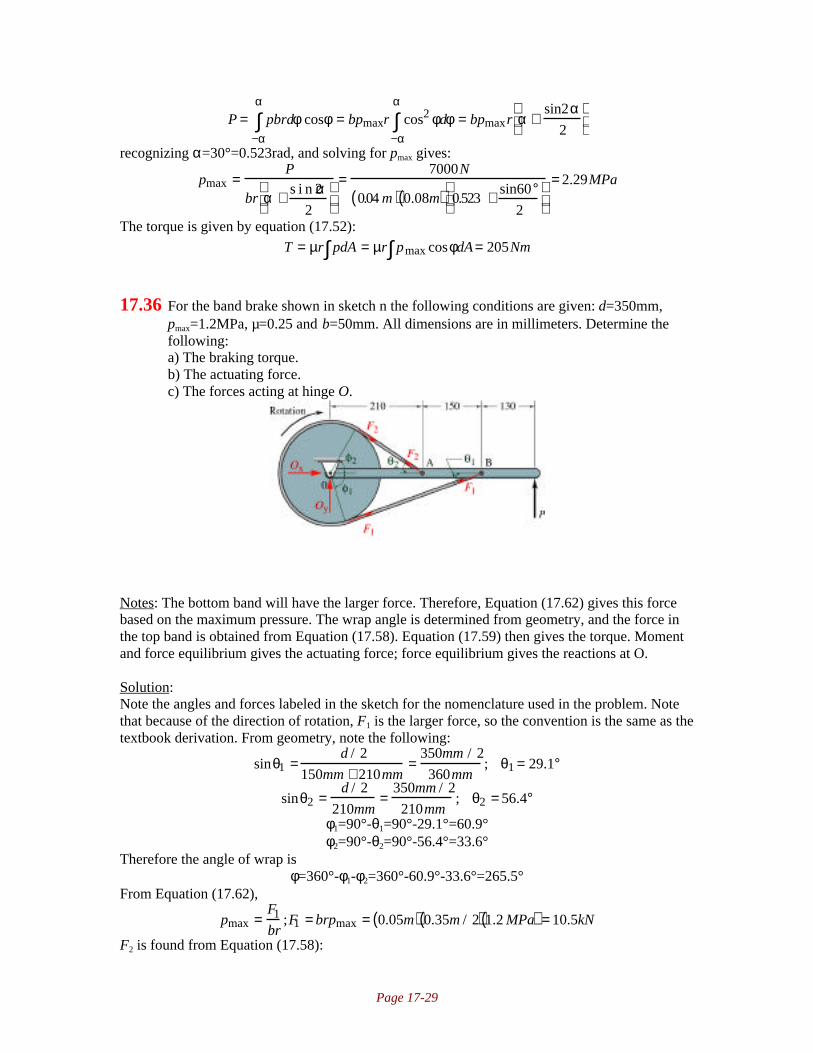
Page 17-29
P = pbrdφ cosφ−α
α
∫ = bpmaxr cos2 φdφ−α
α
∫ = bpmaxr α +sin2α
2
recognizing α=30°=0.523rad, and solving for pmax gives:
pmax =P
br α + s i n 2α2
=7000N
0.04 m( ) 0.08m( ) 0.523 + sin60°2
= 2.29MPa
The torque is given by equation (17.52):
T = µr pdA∫ = µr pmax cosφdA∫ = 205Nm
17.36 For the band brake shown in sketch n the following conditions are given: d=350mm,pmax=1.2MPa, µ=0.25 and b=50mm. All dimensions are in millimeters. Determine thefollowing:a) The braking torque.b) The actuating force.c) The forces acting at hinge O.
Notes: The bottom band will have the larger force. Therefore, Equation (17.62) gives this forcebased on the maximum pressure. The wrap angle is determined from geometry, and the force inthe top band is obtained from Equation (17.58). Equation (17.59) then gives the torque. Momentand force equilibrium gives the actuating force; force equilibrium gives the reactions at O.
Solution:Note the angles and forces labeled in the sketch for the nomenclature used in the problem. Notethat because of the direction of rotation, F1 is the larger force, so the convention is the same as thetextbook derivation. From geometry, note the following:
sinθ1 =d / 2
150mm + 210mm=
350mm / 2
360mm; θ1 = 29.1°
sinθ2 =d / 2
210mm=
350mm / 2
210mm; θ2 = 56.4°
φ1=90°-θ1=90°-29.1°=60.9°φ2=90°-θ2=90°-56.4°=33.6°
Therefore the angle of wrap isφ=360°-φ1-φ2=360°-60.9°-33.6°=265.5°
From Equation (17.62),
pmax =F1
br;F1 = brpmax = 0.05m( ) 0.35m / 2( ) 1.2 MPa( ) = 10.5kN
F2 is found from Equation (17.58):

Page 17-30
F1
F2= eµφπ /180° ; F2 =
F1
eµφπ / 1 8 0° =10.5kN
e 0.25( ) 265.5°( )π / 1 8 0° = 3.30kN
The torque is obtained from Equation (17.59) asT=r(F1-F2)=(0.35m/2)(10.5kN-3.30kN)=1.26kNm
The actuating force is found through moment equilibrium about point O:MO = 0 = P 210mm + 150mm + 130mm( ) − F1sinθ1 210mm + 150mm( ) + F2 sinθ2 210mm( )∑
P = F1 sinθ1 360mm( ) − F2 sinθ2 210mm( )490mm( )
= 10.5kNsin 29.1° 0.36m( ) − 3.3kNs in56.4° 0.21m( )0.49m
or P=2.57kN. The reactions Ox and Oy are found from force equilibrium. For the bar:Fx = 0 = Oxbar − F2 cosθ2 − F1 cosθ1 ; Oxbar = 11kN∑
Fy = 0 = Oybar + F2 sinθ2 − F1 sinθ1 + P; Oybar = 0.21kN∑For the drum:
Fx = 0 = Oxdrum − F2 cosθ2 − F1cosθ1; Oxdrum =11kN∑Fy = 0 = Oydrum − F2 sinθ2 + F1sinθ1; Oydrum = −2.36kN∑
If they are mounted on the same pin, the support reactions need to be subtracted, so that Ox=0kNand Oy=2.57kN.
17.37 The band brake shown in sketch o is 40mm wide and can take a maximum pressure of1.1MPa. All dimensions are in millimeters. The coefficient of friction is 0.3. Determinethe following:a) The maximum allowable actuating forceb) The braking torquec) The reaction supports at O1 and O2
d) Whether it is possible to change the distance O1A in order to have self-locking.Assume point A can be anywhere on line CO1A.
Notes: This is very similar to problem 17.36. As labeled, F1 will be the largest force. Therefore,Equation (17.62) gives this force based on the maximum pressure. The wrap angles aredetermined from geometry, and the force between the drums is obtained from F1 and Equation(17.58). Since the drum mounted on O1 has no applied force, it is an idler, and F3=F2. Equation(17.59) then gives the torque. Moment and force equilibrium gives the actuating force; forceequilibrium gives the reactions at O. Self locking would occur if W=0, and this is investigated bytaking moment equilibrium of bar CB about point O1.
Solution:Note the sketch and the nomenclature used to solve the problem. Note the extra points labeled Gand H. The distance BO2 is obtained from the Pythagorean theorem as
BO2 = 0.18m( )2 + 0.050m( )2 = 0.1868m

Page 17-31
Notice the O2H is the radius of the drum, or 0.1m. Therefore, BH is
BH = 0.1868m( )2 − 0.1m( )2 = 0.1578mθ is obtained from
sinθ =0.1m( )cos θ + 0.05m
0.1578m; θ = 48°
Therefore, φ2=180°+48°=228°. Now note that O1G is the radius of the drum, or 0.1m. Since O1Ais given as 0.135m, and since alternate interior angles are equal, a is
sinα =O1G
O1A=
0.1m
0.135m; α =47.8°
Since F1 is the largest force, it determines the maximum brake lining pressure. From Equation(17.62),
pmax =F1
br;F1 = brpmax = 0.04m( ) 0.1m( ) 1.1MPa( ) = 4.4kN
F2 is found from Equation (17.58):F1
F2= eµφπ /180° ; F2 =
F1
eµφπ / 1 8 0° =4.4kN
e 0.3( ) 228°( )π /180° = 1.33kN
Note that the drum mounted at O1 is an idler; therefore F3=F2=1.33kN, and this drum produces notorque. The torque for the drum mounted at O2 is obtained from Equation (17.59) as
T=r(F1-F2)=(0.1m)(4.4kN-1.33kN)=307NmThe actuating force W is found through moment equilibrium about point O1:
MO1= 0 =∑ W 0.35m( ) − F3sin α 0.135 m( ) − F1sin θ 0.085m + 0.135m( ) − F1 cosθ 0.05m( )
W 0.35 m( )= 1.33kN s in47.8° 0.135m( ) + 4.4kN s i n 4 8° 0.22m( ) + c o s 4 8° 0.05m( )[ ]or W=2.85kN. The reactions O1x and O1y for the bar are found from force equilibrium. For thebar:
Fx = 0 = O1xbar − F3 cosα + F1 cosθ ; O1xbar = −2.05kN∑Fy = 0 = O1ybar − W − F3sinα − F1sinθ ; O1ybar = 7.1kN∑
For the drum:Fx = 0 = O1xdrum − F2 − F3 cosα ; O1xdrum = 2.23kN∑
Fy = 0 = O1ydrum − F3sinα ; O1ydrum = 0.989kN∑If they are mounted on the same supports, then O1x=0.18kN and O1y=8.1kN. For drum 2,
Fx = 0 = O2x − F2 − F1 cosθ ; O2x = 4.27kN∑Fy = 0 = O2y + F1sinθ ; O2y = −3.27kN∑
For the brake to self lock, it would be necessary that F1 be positive for W=0. Taking momentequilibrium for the bar, with the location of A a distance x from point O1:
MO1= 0 = F3 sinα( )x + F1cosθ( )∑ 0.05m( ) + F1sin θ 0.085m + 0.135m( )
This would require x=-0.87m, which is not possible on this bar.

Page 18-1
Chapter 18 • Flexible Machine Elements
18.1 An open flat belt 10 in wide and 0.13 in thick connects a 16-in diameter pulley with a 36in diameter pulley over a center distance of 15 feet. The belt speed is 3600 ft/min. Theallowable preload per unit width of the belt is 100lbf/in, and the weight per volume is0.042 lbf/in
3. The coefficient of friction between the belt material and the pulley is 0.8.
Find the length of the belt, the maximum forces acting on the belt before failure isexperienced, and the maximum power that can be transmitted.
Notes: The length is calculated from Equation (18.5) after α is obtained from (18.4). Thecentrifugal force is given by Equation (18.9). The maximum forces are then obtained fromEquations (18.6) and (18.10). The maximum power that can be transmitted is obtained fromEquation (18.8).
Solution:Note that cd=15ft=180in. Also, the belt cross sectional area is A=twt=(0.13in)(10in)=1.3in
2. The
weight per length is wz’=(0.042lb/in
3)(1.3in
2)=0.0546lb/in. The speed is
3600ft/min=60ft/s=720in/s. From Equation (18.4),
α = sin−1 D2 − D1
2cd
= sin−1 36in− 16in
2 1 5ft( ) 12in / ft( )
= 3.185°
From Equation (18.5),
L = 2cd( )2 − D2 − D1( )2 + π2
D1 + D2( ) +π D2 − D1( )
180°sin−1 D2 − D1
2cd
= 360 in( )2 − 36in −16in( )2 + π2
36in +16in( ) + π 36in −16in( )180°
3.185° = 441in
Assuming the initial preload equals the allowable preload, Fi=1000lb. Therefore, from Equation(18.6),
Fi = F1 + F2
2; F1 = 2Fi − F2 = 2000lb − F2
Equation (18.9) gives the centrifugal force as
Fc = wz′
gu2 = 0.0546lb / in
32.2 ft / s2 60 ft / s( )2 12in / ft( ) = 73.25lb
The wrap angle is, from Equation (18.3),φ1=180°-2α=180°-2(3.185°)=173.6°
Therefore, Equation (18.10) givesF1 − Fc
F2 − Fc= eµφπ /180° = e 0.8( ) 173.6°( )π /180° = 11.29
Substituting for F1 and Fc,2000lb − F2 − 73.25lb
F2 − 73.25lb= 11.29; 12.29F2 = 2753lb; F2 = 224lb
Therefore, F1=2000lb-F2=1776lb. Equation (18.8) gives the power as
hp =F1 − F2( )u33000
= 1776 − 224( ) 3600( )33000
=169hp
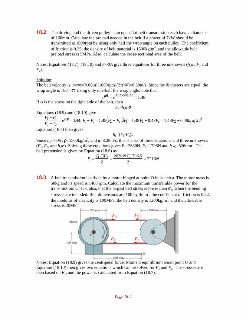
Page 18-2
18.2 The driving and the driven pulley in an open-flat-belt transmission each have a diameterof 160mm. Calculate the preload needed in the belt if a power of 7kW should betransmitted at 1000rpm by using only half the wrap angle on each pulley. The coefficientof friction is 0.25, the density of belt material is 1500kg/m
3, and the allowable belt
preload stress is 5MPa. Also, calculate the cross-sectional area of the belt.
Notes: Equations (18.7), (18.10) and F=σA give three equations for three unknowns (htwt, F1 andF2).
Solution:The belt velocity is u=rω=(0.08m)(1000rpm)(2π/60)=8.38m/s. Since the diameters are equal, thewrap angle is 180°=π. Using only one-half the wrap angle, note that
eµθ = e 0.25( ) π /2( ) = 1.48If σ is the stress on the tight side of the belt, then
F1=htwtσEquations (18.9) and (18.10) give
F1 − Fc
F2 − Fc= eµφ = 1.48; F1 − Fc = 1.48 F2 − Fc( ); F1 = 1.48F2 − 0.48Fc =1.48F2 − 0.48ht wtρu2
Equation (18.7) then giveshp=(F1-F2)u
Since hp=7kW, ρ=1500kg/m3, and u=8.38m/s, this is a set of three equations and three unknowns
(F1, F2, and htwt). Solving these equations gives F1=2630N, F2=1796N and htwt=526mm2. Thebelt pretension is given by Equation (18.6) as
Fi = F1 + F2
2= 2630N +1796N
2= 2213N
18.3 A belt transmission is driven by a motor hinged at point O in sketch a. The motor mass is50kg and its speed is 1400 rpm. Calculate the maximum transferable power for thetransmission. Check, also, that the largest belt stress is lower than σall when the bendingstresses are included. Belt dimensions are 100 by 4mm
2, the coefficient of friction is 0.32,
the modulus of elasticity is 100MPa, the belt density is 1200kg/m3, and the allowable
stress is 20MPa.
Notes: Equation (18.9) gives the centripetal force. Moment equilibrium about point O andEquation (18.10) then gives two equations which can be solved for F1 and F2. The stresses arethen based on F1, and the power is calculated from Equation (18.7).

Page 18-3
Solution:The belt speed is u=rω=(0.075m)(1400)(2π/60)=10.99m/s. Note that the tight side of the belt ison the bottom, so the tension in this side will be labeled F1 as shown. Taking the moments aboutpoint O for the motor,
F2(L1+R)+F1(L1-R)-mgL2=0From Equation (18.9),
Fc = ρAu2 = ρhtw tu2
So that Equation (18.10) becomesF1 − Fc
F2 − Fc= eµφ ;F1 − ρht wtu
2 = eµφ F2 − ρhtw tu2( )
This equation and the moment equation have the unknowns of F1 and F2; substituting the momentequation into the equation above yields F1=1533N and F2=597N. Therefore, the axial stress is
σ1 =F1
htwt=
1533N
0.1m( ) 0.004m( )= 3.833MPa
The bending stress component is, (see page 844),
σb = Ecr
=E ht / 2( )
r= 100MPa( ) 0.002m( )
0.075m= 2.67MPa
The maximum stress is then 2.67MPa+3.833MPa=6.50MPa. This is much less than the allowablestress. The maximum power is calculated from Equation (18.7) as
hp=(F1-F2)u=(1533N-597N)(10.99m/s)=10,290W
18.4 The tension in a flat belt is given by themotor weight, as shown in sketch b. Themass is 80kg and is assumed to beconcentrated at the motor shaft position. Themotor speed is 1405 rpm and the pulleydiameter is 400 mm. Calculate the belt widthwhen the allowable belt stress is 6.00MPa,the coefficient of friction is 0.5, the beltthickness is 5mm, the modulus of elasticity150MPa, and the density is 1200kg/m
3.
Notes: Equation (18.9) gives the centripetal force.The stress is calculated as a combination of axial andbending stress, and set equal to the allowable stress.This combined with moment equilibrium allowssolving for the belt width.
Solution:The belt speed is u=rω=(0.2m)(1405)(2π/60)=29.4m/s. The bending stress in the belt (see page844):
σb = Ecr
=E ht / 2( )
r= 150MPa( ) 0.0025m( )
0.2m= 1.875MPa
The centripetal force is calculated from Equation (18.9) as
Fc = ρAu2 = ρhtw tu2 = 1200kg / m3( ) 0.005m( )wt 29.4m / s( )2 = 5186kg / s2( )wt
Therefore, the stress due to the centripetal force is

Page 18-4
σc = Fc
htwt= 5186kg / s2wt
0.005m( )w t=1.037MPa
Therefore, since the maximum allowable stress is 6MPa, the maximum allowable stress due totension in the belt is
σ1=σall-σb-σc=6MPa-1.875MPa-1.037MPa=3.086MPaNote the sketch shown. From similar triangles, the distance a can be calculated as:
a
700700 − 500( ) /800
+ 250
= 200100 68
; a = 0.740m
Taking moment equilibrium about the hinge point,F1(r+a)+F2(a-r)-Q(0.7)=0
Note that F1=htwtσ1, and since centripetal forces have already been considered, Equation (17.58)gives F2=htwtσ1e
-µφ. Therefore, the moment equation becomes
htwtσ1[a+r+e-µφ
(a-r)]=0.7QTherefore, solving for the belt width,
w t = 0.7Q
htσ1 a + r+ e −µφ a− r( )[ ] =0.7 80kg( ) 9.81m / s2( )
0.005m( ) 3.086MPa( ) 0.74m + 0.2m + e−0.5π 0.74m −0.2 m( )[ ]or wt=0.003384m=33.84mm
18.5 Calculate the maximum possible power transmitted when a full wrap angle is used asshown in sketch c. The belt speed is 5 m/s and the coefficient of friction is 0.19.
Notes: Static equilibrium and Equations (18.7) and (18.10) are needed to solve this problem.
Solution:Note the free body diagrams for the idler:
The transmitted power is from (18.7),

Page 18-5
hp=(F1-F2)uSubstituting (18.7) gives
hp = F2 − htwt ρu2( ) eµφ −1( )uThe presence of a centripetal force will decrease the transmitted power as well as the bearingforce. Equilibrium in the lower part of the free body diagram gives:
F2 − Fc( )s i n 3 0°= mgSo the horsepower becomes
hp = 2mg e0.19π −1( )u = 2 5kg( ) 9.81m / s2( ) 0.8165( ) 5m / s( ) = 400W
18.6 Equation (18.10) gives the belt forces, where F1 is the largest belt force. What is themaximum power the belt can transmit for a given value of F1?
Notes: Equations (18.7), (18.9) and (18.10) give an expression for power in terms of u. Takingthe derivative, setting equal to zero and solving for u gives the optimum velocity. Substitutingthis value into the power expression gives the optimum power.
Solution:From Equation (18.9),
Fc = ′ m u2
where ρ is the weight density of the belt material. Equation (18.10) givesF1 − Fc
F2 − Fc= eµφ ;F1 − Fc = eµφF2 − eµφFc ;F2 =
1
eµφ F1 + eµφ − 1( )Fc( ) = e−µφF1 + 1 − e−µφ( )Fc
Therefore, Equation (18.7) gives
hp = F1 − F2( )u = F1 − e−µφ F1 + 1− e−µφ( )Fc( )u = F1 − Fc( ) 1− e −µφ( )u = 1− e− µφ( ) F1u − Fcu( )Substituting for Fc,
hp = 1− e −µφ( ) F1u − ′ m u2( )u( ) = 1 − e−µφ( ) F1u− ′ m u3( )Taking the derivative with respect to u, setting equal to zero and solving for u gives:
∂hp
∂u= 1− e −µφ( ) F1 − 3 ′ m u 2( ) = 0 ; u2 = F1
3 ′ m ; u = F1
3 ′ m Therefore, Fc becomes
Fc = ′ m u2 = ′ m F1
3 ′ m = F1
3and the maximum horsepower transmitted is:
hp = F1 − Fc( ) 1− e−µφ( )u = F1 − F1
3
1 − e−µφ( ) F1
3 ′ m = 2
31− e−µφ( ) F1
3
3 ′ m = 2
31− e−µφ( ) F1
3
3ρhtwt
18.7 In a flat belt drive with parallel belts the motor and pulley are pivoted at point O asshown in sketch d. Calculate the maximum possible power transmitted at 1200 rpm. Themotor and pulley together have a 50-kg mass at the center of the shaft. The centrifugalforces on the belt have to be included in the analysis. Coefficient of friction is 0.3, beltarea is 300mm
2, and density is 1500kg/m
3.

Page 18-6
Notes: To solve this problem, take equilibrium about the pivot point, then substitute Equation(18.10) to get an expression in terms of F1-Fc. Equation (18.7) then gives the horsepower.
Solution:Note that ω=1200rpm=126rad/s. The belt velocity is u=ωR=126rad/s(0.1m)=12.6m/s. Takingmoments about point O,
M0 = 0 = mgL2 + F1 − Fc( ) R − L1( ) − F2 − Fc( ) R + L1( )∑Note from Equation (18.10),
F2-Fc=(F1-Fc)e-µφ
So the moment equation becomes
mgL2 + F1 − Fc( ) R − L1( ) − F1 − Fc( )e−µφ R + L1( ); F1 − Fc =mgL2
e−µφ R + L1( ) − R − L1( )Equation (18.10) gives
F1 − Fc
F2 − Fc= eµφ ;F1 − Fc = eµφF2 − eµφFc ;F2 =
1
eµφ F1 + eµφ − 1( )Fc( ) = e−µφF1 + 1 − e−µφ( )Fc
Therefore, Equation (18.7) gives
hp = F1 − F2( )u = F1 − e−µφ F1 + 1− e−µφ( )Fc( )u = F1 − Fc( ) 1− e −µφ( )uSubstituting for F1-Fc gives
hp =mgL2
e−µφ R + L1( ) − R − L1( )1− e−µφ( )u =
50kg( ) 9.81m / s2( ) 0.15m( )e− 0.3( )π 0.18m( ) − 0.02m( )
1 − e −0.3 π( ) 12.6m / s( )
or hp=11.3kW.
18.8 A flat belt drive, shown in sketch e, has the top left pulley driven by a motor and drivingthe other two pulleys. Calculate the wrap angles for the two driven pulleys when the fullwrap angle is used on the driving pulley and the power from pulley 2 divided by thepower from pulley 3 is equal to 2. The coefficient of friction is 0.3 and l=4r.

Page 18-7
Notes: The geometry gives the angles φ=10.2° and α1=145.2°. Equation (18.10) is applied threetimes to obtain one expression for the wrap angles α2 and α3. The ratio of horsepower on pulley 2to that on pulley 3 using Equation (18.7) gives a second equation. These then give two equationsand two unknowns.
Solution:Note the terminology which has been added to the sketch. The angle φ is found as:
sinφ = r / 2( )l / 2( ) 2
= r4r 2
= 0.1768; φ = 10.2°
Therefore, the angle θ is θ=90-φ=79.8°. Therefore, α1 is given byα1=360°-90°-45°-79.8°=145.2°
Applying Equation (18.10) three times for the three angles of contact gives:
F3 − Fc = F1 − Fc( )eµα1
F2 − Fc = F1 − Fc( )eµα2
F3 − Fc = F2 − Fc( )eµα3
Therefore,
F3 − Fc = F1 − Fc( )eµα 2eµα 3 = F1 − Fc( )eµα1 ; α1 = α2 + α3Equation (18.10) givesF2 − Fc
F1 − Fc= eµφ ;F2 − Fc = eµα2 F1 − eµα 2 Fc ;F1 = 1
eµα 2F2 + eµα2 −1( )Fc( ) = e−µα2 F2 + 1 − e−µα 2( )Fc
Therefore, Equation (18.7) gives
hp2 = F2 − F1( )u = F2 − e−µα2 F2 + 1− e−µα 2( )Fc( )u = F2 − Fc( ) 1− e−µα2( )uFrom pulley 3, Equation (18.10) gives
F3 − Fc
F2 − Fc= eµφ ;F3 − Fc = eµα 3F2 − eµα3 Fc ; F3 = eµ α3 F2 − eµα 3Fc + Fc
F3 − F2 = eµα3 F2 − eµ α3 Fc + Fc − F2 = eµα 3 −1( ) F2 − Fc( )Therefore, Equation (18.7) gives
hp3 = F3 − F2( )u = F2 − Fc( ) eµα3 −1( )uSince hp2/hp3=2,

Page 18-8
hp2
hp3=
F2 − Fc( ) 1− e−µα2( )uF2 − Fc( ) eµα 3 −1( )u =
1− e −µα 2( )e µα 3 −1( ) = 2
Also, since α1=α2+α3, or α2=145.2°-α3, α2 is then found to be 1.88rad=108° and α3=α1-α2=145.2-108=37.2°
18.9 A flat belt 6 mm thick and 60 mm wide is used in a belt transmission with a speed ratio of1. The radius of the pulleys is 100 mm, their angular speed is 50 rad/s, the center distanceis 1000mm, the belt modulus of elasticity is 200MPa, and the density is 1 kg/dm
3. The
belt is pretensioned by increasing the center distance. Calculate this increase in centerdistance if the transmission should use only half the wrap angle to 1 kW. Centrifugaleffects should be considered. The coefficient of friction is 0.3.
Notes: Equations (18.6), (18.7), (18.9), and (18.10) are used to solve this problem.
Solution:Note that u=(0.1m)(50rad/s)=5m/s. The initial preload is related to the center distance change andgiven by Equation (18.6) as
Fi = ∆aEAL
= F1 + F2
2From Equation (18.9),
Fc=ρbhv2=(1kg/dm
3)(0.006m)(0.060m)(5m/s)
2=9N.
Therefore, from Equation (18.10),F2 − Fc
F1 − Fc= F2 − 9N
F1 − 9N= e−µφ
Also, the horsepower is given from Equation (18.7) ashp=(F1-F2)u=(F2-Fc)(e
µα-1)
Therefore,
Fi = ∆aEAL
=hp eµα +1( )2 eµ α −1( )u + Fc
This results in ∆a=0.008m=8mm.
18.10 A 120-mm wide an 5 mm thick flat belt transfers power from a 250-mm-diameter drivingpulley to a 700 mm diameter driven pulley. The belt has a mass per length of 2.1kg/mand a coefficient of friction of 0.3. The input power of the belt drive is 60kW at 1000rpm. The center distance is 3.5m. Determinea) The maximum tensile stress in the belt.b) The loads for each pulley on the shaft.
Notes: The geometry is as shown in Figure 18.1, and angles α and φ need to be determined. Fc iscalculated from Equation (18.9). Equations (18.7) and (18.10) give two equations to solve for thetwo forces F1 and F2. The maximum stress is then the larger force divided by the area, while thepulley loads are obtained from statics.
Solution:Referring to Figure 18.1 on page 828 for the geometry, α is obtained From Equation (18.4) as:

Page 18-9
sinα =D1 − D2( ) / 2
cd= 700mm − 250mm
2 3500mm( ) ; α = 3.686°
Therefore, since the smaller pulley has the smaller angle of contact, it is the one more likely toslip. Therefore, φ1 is given by
φ1 = 180° −2 3.686°( ) = 172.6° =3.013 radAlso note that the surface speed is
u=ωr=(1000rpm)(2π/60)(0.25m/s)=13.09m/sTherefore, from Equation (18.9),
Fc = ′ m u2 = 2.1kg / m( ) 13.09m / s( )2 = 360NEquations (18.7) and (18.10) give two equations used to obtain F1 and F2:
hp=(F1-F2)u; 60000Nm/s=(F1-F2)(13.09m/s); F1-F2=4584NF1 − Fc
F2 − Fc= eµφ = e0.3 3.013( ) = 2.469; F1 = 2.469F2 −1.469Fc = 2.469 F2 − 529N
Substituting the second equation into the first gives F2=3484N, so that F1=8068N. The maximumstress in the belt is
σ = F1
wt= 8068N
0.12m( ) 0.005m( ) = 13.45MPa
The forces acting on the pulley are, from statics,Fx=(F1-Fc)cosα+(F2-Fc)cosα=(8068N+3484N-2(360N))cos3.686°=10.8kN
Fy=(F1-Fc)sinα-(F2-Fc)sinα=(8068N-3484N)sin3.686°=294N
18.11 A flat belt drive is used to transfer 100 kW of power. The diameters of the driving anddriven pulleys are 300 and 850mm, respectively, and the center distance is 2m. The belthas a width of 200mm, thickness of 10 mm, speed of 20m/s and coefficient of friction of0.35. For a safety factor of 2.0 for static loading, determine the following:a) The belt tensions, contact angles and length for an open configurationb) The loads for each pulley on the axis.
Notes: The angles of interest are obtained from Equations (18.3) and (18.4), and the length from(18.5). The belt tensions are obtained from two simultaneous equations: (18.7) and (18.10). Thepulley loads are obtained from statics.
Solution:Referring to Figure 18.1 on page 828 for the geometry, α is obtained From Equation (18.4) as:
sinα =D1 − D2( ) / 2
cd= 850mm − 300mm
2 2000mm( ) ; α =7.9°
Therefore, since the smaller pulley has the smaller angle of contact, it is the one more likely toslip. Therefore, φ1 is given by Equation (18.3) as:
φ1=180°-2α=180°-2(7.9°)=164.2°=2.866radφ2=180°+2α=180°+2(7.9°)=195.8°=3.417rad
The belt length is, from Equation (18.5),
L = 2cd( )2 − D2 − D1( )2 + π2
D1 + D2( ) +π D2 − D1( )
180°sin−1 D2 − D1
2cd
= 4m( )2 − 0.85m − 0.3 m( )2 + π2
0.85m + 0.3m( ) + π 0.85m − 0.3m( )180°
sin−1 0.85 m − 0.3m
4m
= 5.84m

Page 18-10
Therefore, from Equation (18.9),
Fc = ′ m u2 = 2.kg / m( ) 20m / s( )2 = 800NEquations (18.7) and (18.10) give two equations used to obtain F1 and F2:
hp=(F1-F2)u; 100,000Nm/s=(F1-F2)(20m/s); F1-F2=5000NF1 − Fc
F2 − Fc= eµφ = e0.35 2.866( ) = 2.727; F1 = 2.727 F2 −1.727 Fc = 2.727F2 − 1382N
Substituting the second equation into the first yields F2=3695N. Therefore, F1=8695N.From statics,
Fx=(F1-Fc)cosα+(F2-Fc)cosα=(8695N+3695N-2(800N))cos7.9°=10.7kNFy=(F1-Fc)sinα-(F2-Fc)sinα=(8695N-3695N)sin7.9°=687N
18.12 A synchronous belt transmission is used as a timing belt for an overhead camshaft on acar motor. The belt is elastically prestressed at standstill to make sure it does not slip athigh speeds due to centrifugal forces. The belt is 1100 mm long and weighs 200g. Theelastic spring constant for 1 m of belt material is 10
5N/m. The belt prestress elongates it
2mm. It needs to elongate 4 mm more to start slipping. Calculate the maximum allowablemotor speed if the pulley on the motor shaft has a diameter of 100 mm.
Notes: Equation (18.9) gives the centripetal force in terms of angular velocity. The force dividedby the stiffness gives the elongation, which then can be solved for ω.
Solution:From Equation (18.9),
Fc = ′ m u2 = ′ m ωr( )2
The belt elongation is the force divided by the stiffness, or,
Fcl
105 =′ m u2 l
105 =0 . 2 / 1 . 1( ) ωr( )2
105 /1.1( ) = 5× 10⁻⁹ω2 = 0.002 + 0.004 = 0.006
or ω=1095rad/s=10,460rpm
18.13 A timing belt for power transfer should be used at a velocity ratio of one-third, so that theoutgoing speed should be three times as high as the incoming speed. The material for thebelt reinforcement can be chosen from glass fiber, carbon fiber, and steel wire. Thesematerials give different belt densities as well as different tensile strengths. The glass-fiberreinforced belt has a density of 1400kg/m
3 and an allowable stress of 300MPa. The
carbon-fiber reinforced belt has a density of 1300 kg/m3 and allowable stress of 600MPa.
The steel wire reinforced belt has a density of 2100kg/m3 and an allowable stress of
400MPa. Calculate the maximum power for each belt type if the belt speed is 30 m/s, thebelt cross section size is 50mm
2, and the safety factor is 10.
Notes: The centripetal force is calculated from Equation (18.9). The maximum horsepower isthen calculated from Equation (18.7) including inertia.
Solution:

Page 18-11
From Equation 18.9
Fc = ′ m u2 = ρAu2
Note that the maximum force that can be sustained in the belt is F1=σallA. The area is50mm
2=5x10
-5m
2. The maximum power is then
hp ,max = uns
F1 − Fc( ) = uns
σall A− ρAu2( ) = uAns
σall − ρu2( )Therefore for glass fibers:
hp ,max = uAns
σall − ρu2( ) =30m / s( ) 5 ×10⁻⁵ m2( )
10300MPa −1400kg / m2 30m / s( )2( )
or the maximum power for glass is 44.8kW. For the carbon fibers,
hp ,max = uAns
σall − ρu2( ) =30m / s( ) 5 ×10⁻⁵ m2( )
10600MPa −1300kg / m2 30m / s( )2( )
or the maximum power for carbon fibers is 89.8kW. For the steel wire reinforcement,
hp ,max = uAns
σall − ρu2( ) =30m / s( ) 5 ×10⁻⁵ m2( )
10400MPa − 2100kg / m2 30m / s( )2( )
or the maximum power for steel wire reinforcement is 59.7kW.
18.14 A 25hp, 1750 rpm electric motor drives a machine through a multiple V-belt drive. Thedriver sheave is 3.7 in. in diameter and the wrap angle of the driver is 165°. The weightper length is 0.012lbf/in. Maximum belt preload is 150 lbf, and the coefficient of frictionof the belt material acting on the sheave is 0.2. How many belts should be used? Assumea sheave angle of 18°.
Notes: Equations (18.6) and (18.10) give two equations which are used to obtain the forces F1 andF2. The torque is calculated from Equation (17.59), and Equation (18.8) gives the power per belt.Note that for V-belts, per the discussion on page 834, the flat belt equations are valid if µ isreplaced by µ/sinβ.
Solution:Note that the belt velocity is
u =d
2ω =
3.7in
2
1750rev / m i n( ) 2πrad
rev
1min
6 0 s e c
= 339in / s = 28.25 ft / s =1695 ft / m i n
From Equation (18.9), the centrifugal force is
Fc = wz′
gu2 = 0.012lb / in( )
32.2 ft / s2 28.25 ft / s( )2 12in1 ft
= 3.569lb
The belt forces F1 and F2 are found from Equations (18.6) and (18.10) as:
Fi = 150lb = F1 + F2
2; F1 + F2 = 300lb
F1 − Fc
F2 − Fc= eµφπ /180°sinβ = e 0.2( ) 165( )π / 1 8 0 s i nβ = 6.449; F1 − 3.569lb = 6.449 F2 − 3.569lb( )
Substituting the first equation into the second yields F2=42.88lb. Therefore, F1=257.1 lb. Thetorque is obtained from Equation (17.59) as
T=(F1-F2)(D/2)=(257.1 lb-42.88lb)(3.7in/2)=396.3in-lb.The horsepower per belt is obtained from Equation (18.8) as:

Page 18-12
hp =F1 − F2( )u33000
= 257.1− 42.88( ) 1695( )33000
= 11.0hp
Since 25 hp is required, three belts are needed.
18.15 A V-belt has r1=200mm, r2=100mm, 2β=36° and cd=700mm. The speed of the smaller
sheave is 1200rpm. The cross-sectional area of the belt is 160mm2 and its density is
ρ=1500kg/m3. How large is the maximum possible power transmitted by six belts if each
belt is prestressed to 200N? The coefficient of friction µ=0.30. If 12 kW is transmitted,how large a part of the periphery of the smaller wheel is then active?
Notes: α and φ are found from Equations (18.3) and (18.4). For V-belts, per the discussion onpage 834, the flat belt equations are valid if µ is replaced by µ/sin β. Equations (18.7) and (18.10)are used for to obtain the forces. Equation (18.8) gives the horsepower.
Solution:First of all, note that the velocity is u=rω=(0.1m)(1200rpm)(2πrad/rev)(1min/60s)=12.57m/s.Referring to Figure 18.1 and Equation (18.4),
sinα = D2 − D1
2cd= r2 − r1
cd= 200mm −100mm
700mm= 0.1428; α = 8.213°
From Equation (18.3) for the smaller sheave,φ=180°-2α=180°-2(8.213°)=163.6°
The centripetal force Fc is obtained from Equation (18.9) as
Fc = ′ m u2 = ρAu2 = 1500kg / m2( ) 160mm2( ) 12.57m / s( )2 1m /1000mm( )2 = 37.92N
The belt forces F1 and F2 are found from Equations (18.6) and (18.10) as:
Fi = 200N = F1 + F2
2; F1 + F2 = 400N
F1 − Fc
F2 − Fc= eµφπ /180°sinβ = e 0.3( ) 163.6( )π /180sin18° =15.99; F1 − 37.92 N = 15.99 F2 − 37.92N( )
Substituting the first equation into the second yields F2=57.0N, so that F1=343N. The transmittedhorsepower per belt is, from Equation (18.7),
hp=(F1-F2)u=(343N-57.0N)(12.57m/s)=3595Nm/s=3.595kWTherefore, for six belts, the maximum horespower is 21.57kW.
If 12 kW is transferred and the preload is the same, then Equations (18.6) and (18.7) givetwo equations for F1 and F2:
Fi=200N=(F1+F2)/2; F1+F2=400Nhp=6(F1-F2)u; F1-F2=hp/6u=12kW/(6x12.57m/s=159N
From these equations, F1=279.6N and F2=120.4N. Therefore, the active portion of the sheave isgiven by Equation (18.10) and solving for φ:
F1 − Fc
F2 − Fc= eµφπ /180°sinβ ; e 0.3( )φπ /180sin18° = 279.6N − 37.92N
120.4 N − 37.92 N=2 .930 ; φ = 6 3 . 4°

Page 18-13
18.16 A combined V-belt and flat belt drive, as shown in sketch f, has a speed ratio of 4. ThreeV-belts drive the sheave in three grooves but connect to the larger sheave like flat beltson the cylindrical surface. The center distance is six times the smaller sheave radius,which is 80mm with a speed of 1500rpm. Determine which sheave can transmit a largerpower without slip. Determine the ratio between powers transmitted through the twosheaves. The angle 2β is 36° and the coefficient of friction is 0.30.
Notes: α and φ are found for the two sheaves from Equations (18.3) and (18.4). For V-belts, perthe discussion on page 834, the flat belt equations are valid if µ is replaced by µ/sin β. Equations(18.9) and (18.10) give an equation for the forces F1 and F2. Calculating the power from (18.7)allows for elimination of unknowns and determination of the power ratios.
Solution:Referring to the figure above, and Equation (18.4),
sin β =D2 − D1
2cd=
r2 − r1cd
=4r1 − r1
6r1= 0.5; β = 30°
Using a 2 subscript for the smaller sheave, a 1 for the larger, then from Equation (18.3) for thesmaller sheave,
α2=180°-2α=180°-2(30°)=120°=2π/3and for the larger sheave,
α1=180°+2α=180°+2(30°)=240°=4π/3Equation (18.10) gives for the larger sheave
F1 − Fc
F2 − Fc= eµα1 ; F1 − Fc = eµα2 F2 − eµα1Fc; F1 = e µα 1F2 + 1 − eµα1( )Fc
Therefore, Equation (18.7) gives
hp1 = F1 − F2( )u = eµα1 F2 + 1 − eµα1( )Fc − F2( )u = −1 − eµα1( ) F2 − Fc( )uFor the smaller sheave, we have to substitute µ/sinβ for µ so that
hp2 = − 1 − eµα2 / s i nβ( ) F2 − Fc( )uTherefore, hp1/hp2 is:
hp1
hp2=
1− eµα 1( ) F2 − Fc( )u1 − eµα2 / s i nβ( ) F2 − Fc( )u
=1− eµα 1
1− eµα2 / s i nβ =− 1− e 0.3 4π / 3( )( )
− 1 − e0.3 2π / 3( ) / s i n 1 8°( ) =2.51
6.639= 0.378
Therefore, the smaller sheave can transmit 1/0.378=2.64 times the power of the larger sheave.
Page 18-14
18.17 A V-belt drive for an industrial fan transmits 4kW at a motor speed of 3000 rpm throughfour parallel V-belts of the 4L type. The sheave effective pitch diameter is 4 in, and thespeed ratio is 1. The fan is running continuously. Calculate what the manufacturerspresumed the coefficient of friction to be to get the rated power for the belt drive. Neglectpower variations and assume that all friction forces between the belt and the sheaves aretangent to the sheaves. The density of the V-belt is assumed to be 1000 kg/m
3 and the
prestress gives F1+F2=constant independent of speed. Use the power ratings at 3000 rpmand 5000 rpm for the calculations.
Notes: For a speed ratio of 1, the contact angle is φ=π. Equations (18.10) and (18.7) applied at3000 rpm and (18.7) at 5000 rpm gives a set of three equations which are used to obtain µ. Beltdata must be obtained from Table 18.5(c).
Solutions:Note that φ=π. Table 18.2 on page 836 gives the belt cross section as 1/2 x 5/16 in = 12.7mm x7.94mm. Therefore, wt=12.7mm and ht=7.94mm. The cross sectional area (see Figure 18.4) is
A=(wt-httanβ)ht=(0.0127m-(0.00794)tan18°)(0.00794m)=8.035x10⁻⁵m
2
At 3000 rpm, the horsepower rating is from Table 18.5 (c) as 1.84 hp=1373W, and the belt speedis
u=(3000rpm)(2πrad/rev)(1min/60sec)(2in)(0.0254m/in)=15.96m/sAt 5000 rpm, the horsepower rating is from Table 18.5 (c) as 1.65 hp=1231W, and the belt speedis
u=(5000rpm)(2πrad/rev)(1min/60sec)(2in)(0.0254m/in)=26.60m/sTherefore, Equation (18.9) gives at 3000rpm:
Fc = ′ m u2 = ρAu2 = 1000kg / m3( ) 8.035× 10⁻⁵ m2( ) 15.96m / s( )2 = 20.47 N
and at 5000 rpm,
Fc = ′ m u2 = ρAu2 = 1000kg / m3( ) 8.035× 10⁻⁵ m2( ) 26.60m / s( )2 = 56.85N
Equation (18.10) with µ=µ1/sinβ givesF1 − FcF2 − Fc
= eµφ ; F1 − Fc = eµφ F2 − Fc( ); F1 = eµπ F2 − 20.47N( )+ 20.47N
F1 − F2 =e µπ F2 − 20.47N( ) + 20.47N − F2 = F2 − 20.47N( ) eµπ −1( )Equation (18.7) at 3000 rpm gives:
hp = F1 − F2( )u ;1373W = F2 − 20.47N( ) eµπ −1( ) 15.96m / s( ); F2 = 1373W
15.96m / s( ) eµπ −1( ) + 20.47N
and at 5000 rpm,
hp = F1 − F2( )u ;1231W = F2 − 56.85N( ) eµπ −1( ) 26.60m / s( ); F2 = 1231W
26.6 m / s( ) eµπ −1( ) + 56.85N
Therefore, since F1+F2=constant,
F11+
1373W
15.96m / s( ) eµπ − 1( ) + 20.47N =1231W
26.6m / s( ) eµπ − 1( ) + 56.85N + F12
Solving this for µ gives µ=0.390, and the real friction is µ1=µsin18°=0.12..

Page 18-15
18.18 The input power to shaft A, shown in sketch g, istransferred to shaft B through a pair of mating spurgears and then to shaft C through a 2L-section V-belt drive. The sheaves on shafts B and C have 76-and 200-mm diameters. For the maximum powerthe belt can transfer, determine the following:a) The input and output power torques of thesystem.b) The belt length for an approximate centerdistance of 550mm.
Notes: α must be calculated from Equation (18.3). Powercapacities and correction factors are obtained from Tables18.4 and 18.5. The torque is then calculated from thehorsepower. The belt length is calculated from Equation(18.5).
Solution:Note that the speed of the sheave on shaft B is
N=(1800rpm)(20/50)=720rpmα is calculated from Equation (18.4) as
α = sin−1 D2 − D1
2cd
= sin−1 200mm −76mm
2 550mm( )
= 6.47°
Noting that the pulley diameter is 76mm=2.99in, so from Table 18.5(a), the rated horsepower isinterpolated between the 500rpm rating of 0.06hp and the 1000rpm rating of 0.12 hp as
hpr = 0.12hp − 0.06hp1000rpm − 500rpm
720rpm − 500rpm( ) + 0.06hp = 0.0864hp = 64.45W
Noting that α=6.47°, the loss of contact is 12.94, so Table 18.4 suggests that the correction factorto the rated power is 0.97. Therefore, the maximum power that can be obtained from the belt inthis application is 0.97(64.45W)=62.5W. The input torque on the pulley on shaft B is
TB =hpr
ω= 62.5W
720rpm( ) 2πrad / rev( ) 1min/60s( ) = 0.829Nm
The angular velocity of the pulley on shaft C is
ωC = 720rpm( ) 76mm200mm
= 273.6rpm = 28.65rad / s
so that the torque on shaft C’s pulley is
TC =hpr
ω= 62.5W
28.65rad /s= 2.18Nm
The length of the belt is calculated from Equation (18.5) as
L = 2cd( )2 − D2 − D1( )2 + π2
D1 + D2( ) +π D2 − D1( )
180°sin−1 D2 − D1
2cd
= 1100mm( )2 − 200mm − 76mm( )2 + π2
200mm + 76mm( )+ π 200mm − 76mm( )180°
sin−1 200 − 761100
= 1320mm
or 1.32m.

Page 18-16
18.19 An automobile fan is driven by an engine through a V-belt drive. The engine’s sheave hasa 350-mm diameter and is running at 880 rpm. The fan’s sheave has a 220-mm diameter.The net air drag load of 2.3N is applied tangentially at 330-mm radial distance from thefan axis. Consider 20% loss in other parts of this belt drive and select the size of the V-belt.
Notes: The belt is selected based on the horsepower required in the system. The horsepower iscalculated from Equation (18.12).
Solution:The torque applied to the fan is
T=(2.3N)(0.33m)=0.759NmThe speed of the fan is
ω = 880rpm 350mm / 2 2 0mm( ) = 1400rpm = 146.6rad / sTherefore, the power needed by the fan is
hp=Tω=(0.759Nm)(146.6rad/s)=111.3WSince there are 20% losses in the system, the horsepower which must be transferred by the belt is(1.2)(111.3W)=133.6W. Equation (18.12) gives the rated horsepower, but first note that f1 fromthis equation is taken from Table 18.1 for fans as 1.2. Note also that all three conditions on page
836 exist to some extent, so f2=0.4. Therefore, the required horsepower rating of the belt is
hpr( )input
= hp f1 + f2( ) = 133.6W( ) 1.2 + 0.4( ) = 213.8W = 0.286hp
Note that the smaller pulley is 110mm in radius, or around 4.3 in. The speed of the faster shaft is1400rpm, so reviewing Table 18.5, a 2L section will be too small, while a 3L or a 4L will havesufficient capacity. The cheaper alternative should be selected, which is in all likelihood a 3L.
18.20 A hoist uses a 2 in., 6 x 19 monitor steel wire rope with Lang lay on cast steel sheaves.The rope is used to haul loads up to 8000lbf a distance of 480ft.a) Using a maximum acceleration of 2 ft/s
2, determine the tensile and bending stresses in
the rope and their corresponding safety factors.b) Determine the bearing pressure in the rope and the safety factor when it interacts withthe sheave. Also, determine the stretch of the rope.c) Determine the safety factor due to fatigue and anticipate the number of bends untilfailure.
Notes: Rope properties are obtained from Table 18.7. Equation (18.15) gives the tensile stress,Equation (18.18) the bending stress, Equation (18.19) the bearing pressure (and allowable bearingpressure is obtained from Table 18.9), and the allowable force for fatigue considerations is givenby Equation (18.20).
Solution:From Table 18.7, for 6x19 standard rope, the weight per height is 1.60d
2 lb/ft. Also from Table
18.7, for monitor steel, E=12Mpsi and σall=106ksi. The wire diameter is dw=d/14=1/7in=0.143in,The sheave diameter is D=30d=60in. Therefore, D/dw=420. The weight of the rope is
Fr = 1.60d 2lb / ft( ) 480 ft( ) = 1.6 2( )2( ) 480 ft( ) = 3072lb
The force due to acceleration is
Fa = ma = 8000lb + 3072lb( )32.2 ft / s2 2 ft / s2( ) = 687.7lb

Page 18-17
The total force isFt=Fw+Fr+Fa=8000lb+3072lb+687.7lb=11.76kip
From the text on page 842, Am is roughly 0.38d2=0.38(2in)
2=1.52in
2. Therefore, from Equation
(18.15),
σt = Ft
Am= 11.76kip
1.52in2 = 7737psi
The safety factor for tensile stress is then obtained from Equation (18.16) as
ns = σall
σ t= 106ksi
7.737ksi=13.7
The bending stress is obtained from Equation (18.18):
σb = Edw
D= E
D / dw= 12Mpsi
420= 28.6ksi
So that the safety factor against bending is 106ksi/28.6ksi=3.71. The bearing pressure is obtainedfrom Equation (18.19) as
p = 2Ft
dD=
2 11.76kip( )2in( ) 60 in( ) = 196psi
From Table 18.9, for a 6x19 Lang lay rope and cast steel sheave, the allowable bearing pressure is1000psi. Therefor the safety factor against bearing pressure is ns=1000/196=5.102.
The elongation is given by
δ = FtlAE
=11.76kip( ) 480 ft( ) 12in /1 ft( )
1.52in2( ) 12Mpsi( )= 3.714in
From Equation (18.21) for monitor steel, Su is at least 240ksi, Equation (18.20) then givesthe allowable fatigue force as
Ff = SudD2000
= 240ksi( ) 2in( ) 60in( )2000
=14.4kip
The safety factor against fatigue isnsf=Ff/Ft=14.4kip/11.76kip=1.224
While this apparently is sufficient for infinite life, note that Table 8.8 recommends a safety factorof 5.0 for this application. Therefore, the design is actually insufficient and a redesign would benecessary.
18.21 A steel rope for a crane has a cross-sectional area of 31mm2 and an ultimate strength of
1500N/mm2. The rope is 12m long and is dimensioned to carry a maximum load of
1000kg. If that load is allowed to free-fall 1 m before the rope is tightened, how large willthe stress be in the rope? The modulus of elasticity is 68GPa.
Notes: One merely has to compare the energy of the system before and after free fall. This allowscalculation of the force, and therefore the rope stress.
Solution:The total energy of the system is
mg h+ δ( ) = Fδ / 2where h is the free fall distance of 1m and δ is the maximum elastic deformation in the rope. δ isgiven by
δ = FlAE

Page 18-18
Then the energy equation becomes
mg h + FlAE
= F
Fl2Ae
; F2 l2 AE
− F
mglAE
− mgh = 0
From the quadratic equation, F is 69.3kN. The stress is then
σ = FA
= 69.3kN
31mm2 1000mm / m( )2 = 2236MPa
Therefore, the rope breaks.
18.22 Two 2-cm, 6x19 plow steel wire ropes are used to haul mining material to a depth of
150m at a speed of 8m/s and an acceleration of 1 m/s2. The pulley diameter is 80cm.
Using a proper safety factor, determine the maximum hauling load for these ropes. Aretwo ropes enough for infinite life?
Notes: The total load has to be determined as in Problem 18.20. A safety factor is obtained fromTable 18.8, which then allows calculation of allowable forces.
Solution:From Table 18.7, for 6x19 standard rope, the weight per height is 1.60d
2 lb/ft. Also from Table
18.7, for plow steel, E=12Mpsi and σall=93ksi. From the text on page 842, Am is roughly0.38d
2=0.38(20/25.4)
2=0.236in
2. The weight of the rope is
Fr = 1.60 d 2lb / ft( ) L( ) = 1.620mm
25.4mm / in
2
150m0.3048m / ft
= 488lb
The force due to acceleration is, recongnizing there are two ropes so each carries one-half thehauling force:
Fa = ma =Fw /2 + Fr( )
ga( ) = Fw / 2+ 488lb
32.2 ft / s2 1m / s2( ) 3.28 ft / m( ) = 0.0509Fw + 49.7lb
The total force is
Ft = Fr + Fw
2+ Fa = 488lb + Fw
2+ 0.0509Fw + 49.7lb = 0.5509Fw + 537.7lb
Notice from Table 18.8 that for a mine shaft up to 500ft, the required safety factor is 8.0.Therefore the allowable stress is
σall = σ t
ns= 93ksi
8.0=11.625ksi
Therefore, for tensile overload, the maximum load is
σall = Ft
A= 0.5509Fw + 537.7
0.236in2 =11.625ksi; Fw = 4000lb
For plow steel, from Equation (18.21), Su=240ksi. The fatigue strength is, from (18.20),
Ff = SudD2000
=240ksi( ) 20mm
25.4mm / in
800mm25.4 mm / in
2000= 2.976kip
Ft is, for Fw=4000lb, equal to 2740lb (remember that half the load is carried by each rope).Therefore, the load is marginally below that allowed for infinite life. However, either a ropeinspection program or the use of four cables would be prudent.

Page 18-19
18.23 Using six 16-mm, 6x19 wire ropes, an elevator is to lift a 2500-kg weight to a height of81m at a speed of 4m/s and an acceleration of 1m/s
2. The 726-mm-diameter pulley has a
strength of 6.41 MPa. Determine the safety factors for tension, bending, bearing pressureand fatigue failure. Also, calculate the maximum elongation of the ropes.
Notes: Rope properties are obtained from Table 18.7. Equation (18.15) gives the tensile stress,Equation (18.18) the bending stress, Equation (18.19) the bearing pressure (and allowable bearingpressure is obtained from Table 18.9), and the allowable force for fatigue considerations is givenby Equation (18.20).
Solution:From Table 18.7, for 6x19 standard rope, the weight per height is 1.60d
2 lb/ft. Also from Table
18.7, for plow steel, E=12Mpsi and σall=93ksi. From the text on page 842, Am is roughly0.38d
2=0.38(16/25.4)
2=0.151in
2. The weight of the rope is
Fr = 1.60 d 2lb / ft( ) L( ) = 1.616mm
25.4mm / in
2
81m0.3048m / ft
= 168.7lb
The force due to acceleration is, recognizing there are six ropes so each carries one-sixth thehauling force:
Fa = ma =Fw /6 + Fr( )
ga( ) =
2500kg 2.2lb / kg( ) / 6+168.7lb( )32.2 ft / s2 1m /s2( ) 1 ft /0.3048m( ) = 110.8lb
The total force is
Ft = Fr + Fw
6+ Fa = 168.7 lb+ 110.8lb +
2500kg( ) 2.2 lb / kg( )6
=1198lb
For tensile overload, equation (18.15) gives
σt = Ft
Am= 1198lb
0.151in2 = 7.93ksi
Since D/d=726/16=45.4, Figure (18.7) suggests the rope will have around a 5% loss in strength.Therefore, the safety factor is given by Equation (18.16) as
ns = 0.95σall
σ t= 0.95( ) 93ksi( )
7.93ksi= 11.1
For bending stress, dw=d/16=1mm, so that D/dw=726. The bending stress is obtained fromEquation (18.18):
σb = Edw
D= E
D / dw= 12Mpsi
726= 16.53ksi
So that the safety factor against bending is 93ksi/16.53ksi=5.63. The bearing pressure is obtainedfrom Equation (18.19) as
p = 2Ft
dD= 2 1198lb( )
1 6 / 2 5 . 4in( ) 7 2 6 / 2 5 . 4in( ) = 133.1psi
Therefore the safety factor against bearing pressure is ns=6.41/[(0.1331)(6.895)]=6.985.From Equation (18.21) for monitor steel, Su is at least 240ksi, Equation (18.20) then gives
the allowable fatigue force as
Ff = SudD2000
= 240ksi( ) 1 6 / 2 5 . 4in( ) 7 2 6 / 2 5 . 4in( )2000
= 2.16kip
The safety factor against fatigue isnsf=Ff/Ft=2.16kip/1198lb=1.80
The elongation is given by

Page 18-20
δ =Ftl
AE=
1198lb( ) 81
0.3048ft
0.151in2( ) 12Mpsi( )= 0.1757 ft = 2.11in = 53.6 mm
18.24 Sketch h shows a wire rope drive usedon an elevator to transport dishesbetween floors in a restaurant. Themaximum mass being transported is300kg and hangs by a steel wire. Theline drum is braked during thedownward motion by 800Nm. Therotating parts have a mass moment ofinertia of 13kg-m
2. Calculate the
maximum force in the wire and when itfirst appears.
Notes: This is a rather complicated problem,requiring the determination of the differentialequation of motion for the weight and for thedrum.
Solution:A free body diagram of the system is shown. The extra elongation from the brake force gives
x = φr + F − mg( ) LAE
The rotational motion givesJ˙ ̇ φ = Fr − T
and the force on the mass ism˙ ̇ x = mg − F
Therefore, differentiating the first equation gives
˙ ̇ x = ˙ ̇ φ r + ˙ ̇ F L
AE
Substituting C=AE/L, and substituting for the second derivatives of x and φ,
mg − Fm
= Fr − T( )rJ
+ ˙ ̇ F 1C
; ˙ ̇ F + C
1m
+ r2
J
F =C g + Tr
J
The particular solution to this differential equation is
F = mgJ + mrT
J + mr2
The complimentary solution is
F = Ceλt ; λ2 + C1m
+ r2
J
= 0; λ = ±i
Cm
+ Cr2
J; ωe = C
m+ Cr2
J
Therefore,
F = C1sin ωet + ψ0( ) + mgJ + mrT
J + mr2

Page 18-21
The boundary conditions are that at t=0, x=φr and F=mg. Therefore,
˙ x = ˙ φ r → ˙ F = 0; mg = C1 sinψ0 + mgJ + mrT
J + mr2
Therefore,
˙ F = C1ωe cos ωet + ψ 0( ) = 0; ψ0 = ± π2
; C1 = ± m2gr2 − mrT
J + mr2
Since T=800Nm>(300)(9.81)(0.2)=588=mrg, Fmax is
Fmax =m2gr2 − mrT
J + mr2 + mgJ + mrT
J + mr2 = 2mrT − m2gr2 + mgJ
J + mr2 = 3960N
The maximum force occurs when sin(ωet+π/2)=-1 so that
t =π
ωe=
π
C
m+ Cr2
J
= 0.1327s
18.25 End and front views of a hoisting machine are shown in sketch i. Calculate the liftingheight per drum revolution. Calculate the maximum force in the wire when the drum isinstantly started with angular speed ω to lift a mass m. The free length of the wire is Land its cross sectional area is A. The modulus of elasticity of the wire is E.
Notes: This problem requires solution of the differential equations of motion for the hoist.
Solution:The free body diagram is shown. Each revolution lifts the mass a distance π(R-r). Therefore,
m˙ ̇ x = 2P − mgThe motion and wire elasticity give
Rω − rω( )dt = 2dx + LAE
dp; dxdt
= R − r( )ω2
− L2AE
dPdt
; d 2x
dt2 = − L2AE
d2P
dt2
Substituting into the first equation gives
mL2AE
d2 P
dt2 + 2P = mg
P=Ceλt gives
mL2AE
λ2 + 2 = 0; λ = ±i4AEmL
; ωe = 4AEmL
So that P is given by

Page 18-22
P = B cosωet + Csinωe t+ mg2
The boundary conditions are that at t=0, dx/dt=0 , B=0, so that
R − r( )ω = LAE
dPdt
t=0= L
AE
Cωe; C = ω R − r( )
2mAE
LThe maximum force is
Pmax = mg2
+ m R − r( )2
mAEL
18.26 A hauling unit with 25-mm, 8x19 wire rope made of fiber-core plow steel is used to raise
a 45-kN load to a height of 150m at a speed of 5 m/s and an acceleration of 2m/s2. Design
for a minimum pulley diameter while determining the safety factors for tensile strength,bending stress, bearing pressure and fatigue endurance.
Notes: Rope properties are obtained from Table 18.7. Equation (18.15) gives the tensile stress,Equation (18.18) the bending stress, Equation (18.19) the bearing pressure (and allowable bearingpressure is obtained from Table 18.9), and the allowable force for fatigue considerations is givenby Equation (18.20).
Solution:Note that the load is Fw=45kN=10.12kip. From Table 18.7, for 8x19 rope, the weight per height is1.45d
2 lb/ft. Also from Table 18.7, for plow steel, E=10Mpsi and σall=80ksi. From the text on
page 842, Am is roughly 0.38d2=0.38(25/25.4)
2=0.368in
2. The weight of the rope is
Fr = 1.45d2lb / ft( ) L( ) = 1.4525mm
25.4mm / in
2
150m0.3048m / ft
= 691.3lb
The force due to acceleration is
Fa = ma =45kN
1kip4.448kN
+ 691.3lb
32.22m / s2( ) 1 ft
0.3048m
= 2202lb
The total force isFt = Fr + Fw + Fa = 691.3lb +10,120 lb+ 2202 lb =13.01kip
For tensile overload, equation (18.15) gives
σt = Ft
Am= 13.01kip
0.368in2 = 35.35ksi
Since D/d=21, Figure (18.7) suggests the rope will have around a 7% loss in strength. Therefore,the safety factor is given by Equation (18.16) as
ns = 0.93σall
σ t= 0.93( ) 80ksi( )
35.35ksi= 2.10
For bending stress, dw=d/19=2.67mm, so that D/dw=399. The bending stress is obtainedfrom Equation (18.18):
σb = Edw
D= E
D / dw= 10Mpsi
399= 25.06ksi
So that the safety factor against bending is (0.93)80ksi/25.06ksi=2.99. The bearing pressure isobtained from Equation (18.19) as
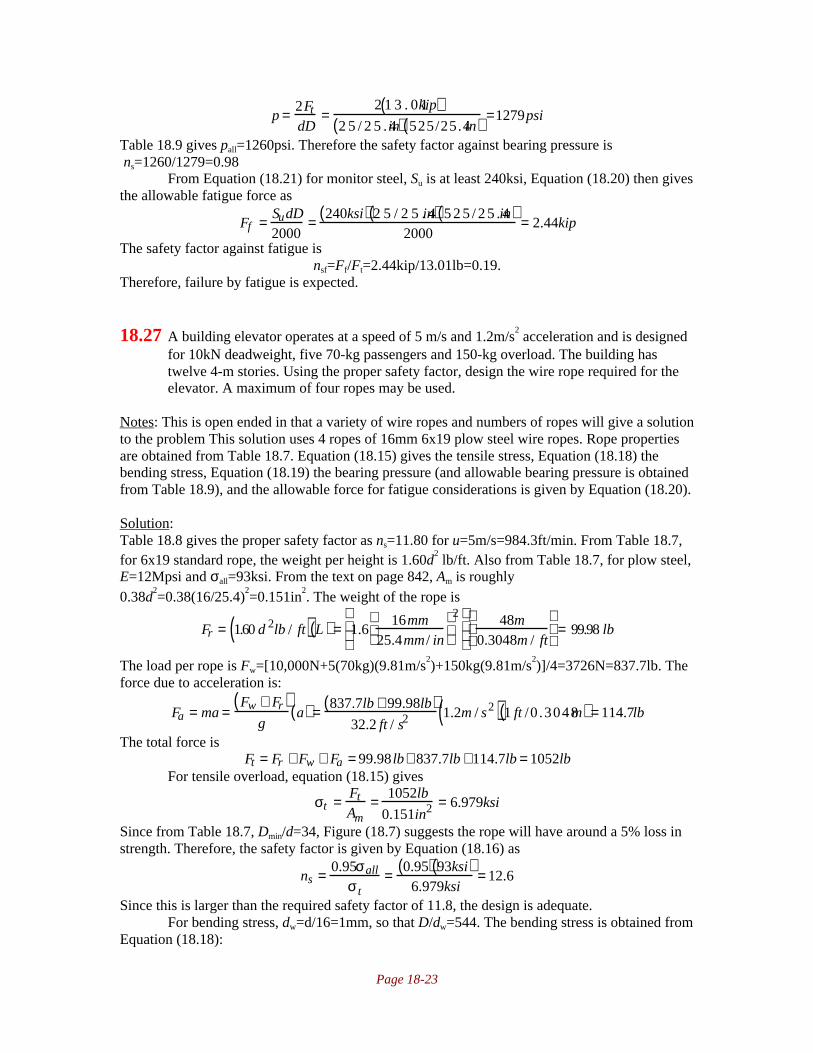
Page 18-23
p = 2Ft
dD=
2 1 3 . 0 1kip( )2 5 / 2 5 . 4in( ) 525/25.4in( ) =1279psi
Table 18.9 gives pall=1260psi. Therefore the safety factor against bearing pressure is ns=1260/1279=0.98
From Equation (18.21) for monitor steel, Su is at least 240ksi, Equation (18.20) then givesthe allowable fatigue force as
Ff = SudD2000
= 240ksi( ) 2 5 / 2 5 . 4in( ) 5 2 5 / 2 5 . 4in( )2000
= 2.44kip
The safety factor against fatigue isnsf=Ff/Ft=2.44kip/13.01lb=0.19.
Therefore, failure by fatigue is expected.
18.27 A building elevator operates at a speed of 5 m/s and 1.2m/s2 acceleration and is designed
for 10kN deadweight, five 70-kg passengers and 150-kg overload. The building hastwelve 4-m stories. Using the proper safety factor, design the wire rope required for theelevator. A maximum of four ropes may be used.
Notes: This is open ended in that a variety of wire ropes and numbers of ropes will give a solutionto the problem This solution uses 4 ropes of 16mm 6x19 plow steel wire ropes. Rope propertiesare obtained from Table 18.7. Equation (18.15) gives the tensile stress, Equation (18.18) thebending stress, Equation (18.19) the bearing pressure (and allowable bearing pressure is obtainedfrom Table 18.9), and the allowable force for fatigue considerations is given by Equation (18.20).
Solution:Table 18.8 gives the proper safety factor as ns=11.80 for u=5m/s=984.3ft/min. From Table 18.7,for 6x19 standard rope, the weight per height is 1.60d
2 lb/ft. Also from Table 18.7, for plow steel,
E=12Mpsi and σall=93ksi. From the text on page 842, Am is roughly0.38d
2=0.38(16/25.4)
2=0.151in
2. The weight of the rope is
Fr = 1.60 d 2lb / ft( ) L( ) = 1.616mm
25.4mm / in
2
48m0.3048m / ft
= 99.98 lb
The load per rope is Fw=[10,000N+5(70kg)(9.81m/s2)+150kg(9.81m/s
2)]/4=3726N=837.7lb. The
force due to acceleration is:
Fa = ma =Fw + Fr( )
ga( ) = 837.7lb + 99.98lb( )
32.2 ft / s21.2m / s2( ) 1 ft /0 .3048m( ) = 114.7lb
The total force isFt = Fr + Fw + Fa = 99.98 lb+ 837.7lb +114.7lb = 1052lb
For tensile overload, equation (18.15) gives
σt = Ft
Am= 1052lb
0.151in2 = 6.979ksi
Since from Table 18.7, Dmin/d=34, Figure (18.7) suggests the rope will have around a 5% loss instrength. Therefore, the safety factor is given by Equation (18.16) as
ns = 0.95σall
σ t= 0.95( ) 93ksi( )
6.979ksi= 12.6
Since this is larger than the required safety factor of 11.8, the design is adequate.For bending stress, dw=d/16=1mm, so that D/dw=544. The bending stress is obtained from
Equation (18.18):

Page 18-24
σb = Edw
D= E
D / dw= 12Mpsi
544= 22.06ksi
So that the safety factor against bending is (0.95)93ksi/22.06ksi=4.00. The bearing pressure isobtained from Equation (18.19) as
p = 2Ft
dD= 2 1052lb( )
1 6 / 2 5 . 4in( ) 5 4 4 / 2 5 . 4in( ) = 156psi
Table 18.9 gives pall=900psi for cast steel. Therefore the safety factor against bearing pressure isns=900/156=5.77.
From Equation (18.21) for monitor steel, Su is at least 240ksi, Equation (18.20) then givesthe allowable fatigue force as
Ff = SudD2000
= 240ksi( ) 1 6 / 2 5 . 4in( ) 5 4 4 / 2 5 . 4in( )2000
= 1.62kip
The safety factor against fatigue isnsf=Ff/Ft=1.62kip/1052lb=1.54
18.28 A three-strand, ANSI 50 roller chain is used to transfer power from a 20-tooth drivingsprocket that rotates at 500 rpm to a 65-tooth driven sprocket. The input power is from aninternal combustion engine, and the chain experiences medium shock. Determine thefollowing:a) The normal powerb) The length of the chain for an approximate center distance of 550mmc) The chordal speed variation
Notes: The normal power is calculated from Equation (18.32) with coefficients from Tables(18.12) and (18.13). The chain length is calculated from (18.26).
Solution:Note that Np=20, Na=500rpm. Using data from Table 18.11, hp=1.18(5.71)(0.746)=5.03kW. FromTables (18.12) and (18.13), a1=1.2 and a2=2.5. Therefore, from Equation (18.32),
hpr=hpa1/a2=5.03kW(2.5)/(1.2)=10.5kW per chainFor ANSI 50 chain, Table 18.10 on page 850 gives pt=5/8in=15.88mm. Therefore, the chainlength is calculated from (18.26) as:
Lpt
= 2cd
pt+ N1 + N2
2+
N2 − N1( )2
4π 2 cd / pt( )= 2
55015.88
+ 20 + 65( )
2+ 65 − 20( )2
4π 2 550 /15.88( )=113.26
Since a chain must have an integer number of links, we take L/pt=114, so that L=1810mm. Thespeed fluctuation is
∆VV
= 100 1 − cos18020
= 1.23%
18.29 To transfer 100kW of power at 400rpm, two strands of roller chain are needed. The loadcharacteristics are heavy shock, poor lubrication, average temperature, and 16hr ofservice per day. The driving sprocket has 13 teeth and the driven sprocket has 42 teeth.Determine the kind, length and size of the chain for a center distance close to 50 pitches.
Notes: This is an open-ended problem in that a number of chains will give an acceptable answer.This solution uses ANSI 200 chain with 13 tooth driving sprocket. The normal power is

Page 18-25
calculated from Equation (18.32) with coefficients from Tables (18.12) and (18.13). The chainlength is calculated from (18.26).
Solution:From Tables (18.12) and (18.13), a1=1.4 and a2=1.7. Therefore, from Equation (18.32),
hpr=hpa1/a2=100kW(1.4)/(1.7)=82.35kW per chainFor ANSI 200 with 13 tooth driving sprocket, Table 18.10 gives pt=2.5in=63.5mm. If cd=50pt,then Equation (18.26) gives
Lpt
= 2cd
pt+ N1 + N2
2+
N2 − N1( )2
4π 2 cd / pt( )= 2 50( ) + 13+ 42( )
2+ 42 −13( )2
4π 2 50( )= 127.9
Since a chain must have an integer number of links, we take L/pt=128, so thatL=128(63.5mm)=8128mm=8.128m.
18.30 A two strand AISI 80 roller chain system is used to transmit the power of an electricmotor rotating at 500 rpm. The driver sprocket has 12 teeth and the driven sprocket has60 teeth. The operating condition is specified by precision mounting and light shock.Calculate the power rating, the chordal speed variation, and the chain length for themaximum center distance.
Notes: The normal power is calculated from Equation (18.32) with coefficients from Tables(18.12) and (18.13). The chain length is calculated from (18.26).
Solution:Note that hp=(0.62)(16.85)=10.45kW. Tables (18.12) and (18.13) give a1=1 and a2=1.7. FromEquation (18.32) gives
hpr=hpa1/a2=10.45kW(1)/(1.7)=6.15kW per chainThe chordal speed variation is given by:
∆VV
= 100 1 − cos18012
= 3.41%
The center distance is recommended to be between 30 and 50 pitches in the text on page 854.Therefore, using cd=50pt, the chain length is calculated from Equation (18.26) as
Lpt
= 2cd
pt+ N1 + N2
2+
N2 − N1( )2
4π 2 cd / pt( )= 2 50( ) + 12 + 60( )
2+ 60 −12( )2
4π2 50( )=137.2
Since a chain must have an integer number of links, we take L/pt=138, so thatL=138(25.4mm)=3505mm=3.505m
18.31 A roller chain is used to transfer 9kW of power from a 20-tooth driving sprocket runningat 600rpm to a driven sprocket with speed ratio of 4:1. Design the chain drive for heavyshocks, 20 hr of service per day, and poor lubrication. Also, determine the required chainlength for a center distance of approximately 70 pitches.
Notes: The normal power is calculated from Equation (18.32) with coefficients from Tables(18.12) and (18.13). The chain length is calculated from (18.26).

Page 18-26
Solution:The speed ratio is 4:1, so that N2=4N1=4(20)=80 teeth. Tables (18.2) and (18.3) give a1=1.4 anda2=1. Therefore the rated power is obtained from Equation (18.32) as:
hpr=hpa1/a2=9kW(1.4)/(1)=16.89kW per chainReferring to Table 18.11, for a 20 tooth sprocket, ANSI 80 has hp=23.75kW, and this will beused. For this, the pitch is pt=1in =25.4mm. The length is given by Equation (18.26):
Lpt
= 2cd
pt+ N1 + N2
2+
N2 − N1( )2
4π 2 cd / pt( )= 2 70( )+ 20 + 80( )
2+ 80 − 20( )2
4π 2 70( )= 191.3
Since a chain must have an integer number of links, we take L/pt=192, so thatL=192(25.4mm)=4877mm=4.877m