solenoid powered to open / spring to close (failsafe) · fs3 valves: application the fs3 version of...
TRANSCRIPT

FS3 Valves Solenoid Powered to Open / Spring to Close (failsafe)
Part of the F Series of easily installed, compact, air intake valves for diesel engine emergency shutdown.

2
About Wyndham Page LtdBased in the UK Wyndham Page specialise in the design and manufacture of safety equipment for diesel engines.
Our product range of Air Intake Shutdown Valves includes our E Series Automatic Valves and our F Series Butterfly Valves with solenoid, pneumatic or manual actuation options. We offer Speedswitch kits for the F Series valves and a range of Spark Arresters designed to prevent the emission of high energy sparks from diesel exhaust systems.
Wyndham Page is headed by Freddy Page-Roberts who brings over 20 years’ experience in the diesel safety industry and was previously managing director of Chalwyn Ltd.
All members of the senior management team have considerable experience in organisations specialising in the design and manufacture of hazardous area equipment for diesel engines.
Quality Assurance Wyndham Page Valves are manufactured and tested under our EN ISO 9001: 2015 quality management system.
Wyndham Page Ltd are certified to supply ATEX equipment under Quality assurance Certificate CML ATEXQ11003.
• Equipment supplied with an EC Type Examination Certificate is CE marked and meets the provision of the ATEX directive 2014/34/EU.
• Self-certified equipment supplied with an EU Type Examination Certificate is CE marked and meets the provision of the ATEX directive 2014/34/EU.

3
FS3 Valves: ApplicationThe FS3 version of the Wyndham Page F Series of shutdown valves is designed to be installed in the air intake system of a diesel engine to provide an emergency means of rapid shutdown.
An electrical signal must be applied continuously to hold the FS3 valve in the open state to enable the engine to be started and run. Loss of this electrical signal results in closure of the valve thereby bringing the running engine to a stop within a few seconds.
An electrical shutdown control system is required to interrupt the electrical signal to the valve automatically on engine overspeed or any other selected fault condition. Additionally a manual emergency stop button to enable the electrical signal to the valve to be switched off should be incorporated.
Any loss of power supply to the shutdown control circuit or fault within the control circuit causing loss of signal output would also result in an engine shutdown.
The low intake air flow restriction through the open valve makes it generally compatible with the requirements of low emission diesel engines.
Corrosion resistant materials are used where applicable in the construction of the valve. This lightweight and compact valve design together with the availability of factory fitted hose adaptors selected from a wide range of optional sizes assists in easy installation.
The valve may be fitted to either turbocharged or naturally aspirated engines. In the case of turbocharged engines temperature limitations may restrict the position in which the valve may be installed in the intake system.
Note. An ATEX version of this valve is available. Wyndham Page also supply engine speed switches for incorporation into the emergency shutdown control circuit of this type of application. Please contact Wyndham Page or your Wyndham Page supplier for details.

4
Description and Main DimensionsVersions of the FS3 valve can be selected to operate by either a 12 volt or 24 volt run signal.
In standard form the FS3 valve is available complete with hose adaptors as selected by the customer from a range of standard sizes – see diagram below and data on pages 5 and 6. Where a requirement exists for a non-standard adaptor size or other alternative form of intake pipe connection such as bolted joint, please pass details of requirement to Wyndham Page or your Wyndham Page supplier for investigation.
Optionally the valve can be supplied fitted with an internal microswitch to indicate the open/closed status of the valve.
The valve has a metal to metal seal when closed. It is designed for low closing friction and long life of the sealing surfaces. The internal mechanism is configured to withstand high shock loads without malfunction.
The electrical enclosure is to IP66.
The diagram below and the diagrams and data on pages 5 to 7 cover the main features and basic dimensions of the FS3 range including selection of options and order coding.
D
E
E
H
H
OSE
ADA
PTO
R
45
B
AVALVEBORE
C
HOSE ADAPTOR
LABEL:AIRFLOW ARROW
SAFETY NOTICE
CABLESSOLENOID &
MICROSWITCH (IF FITTED)
LABEL:SERIAL No
PART NoRATING
71 (77) ( ) = APPLIES TO 203 VALVE
21(27)
30
(42)
100
(110
)

5
D
E
E
H
H
OSE
ADA
PTO
R
45
B
AVALVEBORE
C
HOSE ADAPTOR
LABEL:AIRFLOW ARROW
SAFETY NOTICE
CABLESSOLENOID &
MICROSWITCH (IF FITTED)
LABEL:SERIAL No
PART NoRATING
71 (77) ( ) = APPLIES TO 203 VALVE
21(27)
30
(42)
100
(110
)
METRIC TABLE DIMENSIONS (MM)
WEI
GH
T KG
ORD
ER
CODE
MODEL
H TO SUIT HOSE BORE
BOREA B C D E
FS3
38
57 81 131 50 20
1.47 03844 1.47 04451 1.47 05157 1.46 05764 1.46 06470 1.51 07070 65 91 141 28 25 1.38 70S76
71 99 149 28 251.44 076
83 1.53 08389 1.60 08995 1.68 095102
95 125 175 35 251.77 102
108 1.85 108114 1.94 114121 2.05 121127
120 154 204 42 252.24 127
133 2.34 133140 2.47 140146 2.58 146152
145 185 236 49 25
3.04 152159 3.18 159165 3.30 165171 3.44 171178 3.61 178203 192 238 291 65 40 5.69 203
6
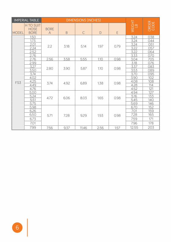
IMPERIAL TABLE DIMENSIONS (INCHES)
WEI
GH
T LB
ORD
ER
CODE
MODEL
H TO SUIT HOSE BORE
BOREA B C D E
FS3
1.50
2.2 3.18 5.14 1.97 0.79
3.24 0381.73 3.24 0442.01 3.24 0512.24 3.22 0572.52 3.22 0642.76 3.33 0702.76 2.56 3.58 5.55 1.10 0.98 3.04 70S2.99
2.80 3.90 5.87 1.10 0.983.18 076
3.27 3.37 0833.50 3.53 0893.74 3.70 0954.02
3.74 4.92 6.89 1.38 0.983.90 102
4.25 4.08 1084.49 4.28 1144.76 4.52 1215.00
4.72 6.06 8.03 1.65 0.984.94 127
5.24 5.16 1335.51 5.45 1405.75 5.69 1465.98
5.71 7.28 9.29 1.93 0.98
6.70 1526.26 7.01 1596.50 7.28 1656.73 7.59 1717.01 7.96 1787.99 7.56 9.37 11.46 2.56 1.57 12.55 203

7
Special features code (refer to sales)Microswitch option: MVoltage: 12 or 24Adaptor size (order code in table)
FS3 - XXX - XX - M - S000
Order Coding
Special Features: By arrangement with Wyndham Page.
Valve SelectionTo enable Wyndham Page to select the most suitable version of the FS3 valve for the Customers application the following data is required:
[1]. Bore size of the intake hose into which the intake valve is to be fitted - refer to section headed “Installation [mechanical]”.
[2]. Whether a 12 volt or 24 volt shutdown signal is to be used.
[3]. Whether a built in microswitch is required.

8
Installation [mechanical]Select a position for the valve which meets the requirements below and also permits a suitable run for the connected electrical cables. Ensure direction of the engine intake airflow complies with that marked on the valve. If an engine air intake system flametrap is also fitted, the shutdown valve must be installed upstream (air cleaner side) of the flametrap.
The valve may be fitted in any attitude from horizontal to vertical but not in a position where it is subjected to temperatures , internal or external, outside of the range -40C to +120C.
Additionally in the case of naturally aspirated engines fit the valve as close as possible to the intake manifold.
For turbocharged engines fit the valve upstream of the turbocharger except where an air charge cooler is fitted in which case it may be fitted downstream of the charge cooler subject to not exceeding the +120C limit. Do not fit valve between the turbocharger and charge cooler.
The valve must always be fitted downstream of an engine air filter.
The hose and associated intake system into which the valve is installed should be adequate to fully support the valve whilst not permitting excessive vibration of the valve. Generally ensure that there is sufficient flexibility in the finalised intake system to allow for the necessary relative movement between the intake system components over the full range of engine operating conditions to avoid excessive mechanical stresses.
Any existing crankcase breather arrangement venting directly into the engine intake ports or into the intake system downstream of the FS3 valve, must be sealed and replaced by a crankcase breather arrangement connected into the intake system upstream of the FS3 valve or, if permitted at the operating site, vented to atmosphere.
Important Note. Retain the standard fuel shutdown stop fitted to the engine. The Wyndham Page FS3 air intake valve is designed for emergency stop only.

FS3 VALVE: INTERNAL WIRING SCHEMATICMICROSWITCH OPTIONAL
FS3 VALVE: 12 OR 24 V WITH OPTIONAL M MICROSWITCH
RED:HOLD
+
WHITE:PULL+
ENERGISED
MICROSWITCHVALVE OPEN: 1-2VALVE CLOSED: 1-4
AIRFLOW
1
2
4
ENERGISETO
OPEN
BLACK:COM-
VALVENORMALLYCLOSED
IP66 ENCLOSURE
HOLD
COIL
PULLCOIL
BLUE
BLACK
BROWN
Microswitch OptionFS3 Valve: Internal wiring schematic
9
Installation [electrical]The wiring diagrams show the connections for the valve solenoid and, where applicable, the optional microswitch.
The electrical data for the solenoid and microswitch is tabulated on page 10.
It is recommended that a manual switch for emergency stop is always incorporated into the control shutdown control circuit to switch off the electrical signal to the FS3. This manual switch should be a type that requires reset to the run status after operation.
Important notes.Design of the electrical shutdown system must take into account the limitations applicable in terms of applying power to the solenoid [see solenoid electrical specification on page 10].
10
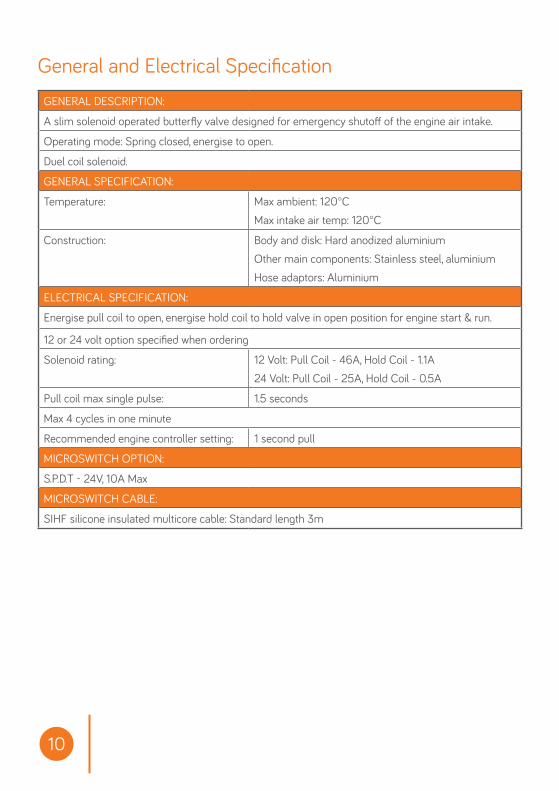
GENERAL DESCRIPTION:
A slim solenoid operated butterfly valve designed for emergency shutoff of the engine air intake.
Operating mode: Spring closed, energise to open.
Duel coil solenoid.
GENERAL SPECIFICATION:
Temperature: Max ambient: 120°CMax intake air temp: 120°C
Construction: Body and disk: Hard anodized aluminiumOther main components: Stainless steel, aluminiumHose adaptors: Aluminium
ELECTRICAL SPECIFICATION:
Energise pull coil to open, energise hold coil to hold valve in open position for engine start & run.
12 or 24 volt option specified when ordering
Solenoid rating: 12 Volt: Pull Coil - 46A, Hold Coil - 1.1A24 Volt: Pull Coil - 25A, Hold Coil - 0.5A
Pull coil max single pulse: 1.5 seconds
Max 4 cycles in one minute
Recommended engine controller setting: 1 second pull
MICROSWITCH OPTION:
S.P.D.T - 24V, 10A Max
MICROSWITCH CABLE:
SIHF silicone insulated multicore cable: Standard length 3m
General and Electrical Specification

11
OperationArrange the shutdown control circuit system such that the 12 volt or 24 volt run signal as applicable is applied to the FS3 valve when engine start up is required.
Normal engine shutdown should always be via the standard fuel shutdown.
Should the engine standard fuel shutdown fail to stop the engine operate the manual emergency stop in the shutdown control system to break the 12 volt or 24 volt supply to the FS3 valve.
The FS3 valve has no manual reset facility. It can only be operated by the application or removal of an electrical signal at the appropriate voltage.
Where fitted the valves internal microswitch permits an indication of the valves open / closed status.
MaintenanceThe following maintenance schedule should be undertaken. Subject to experience of local operating conditions the frequency of the maintenance schedule may be varied. Carry out the proposed maintenance work when the equipment is in a safe area and record details of the work carried out. Rectify any problems identified before returning the diesel powered equipment back into service.
FOLLOWING INITIAL INSTALLATION AND THEREAFTER AT WEEKLY INTERVALS: [1]. Check all intake pipework between the FS3 valve and engine intake manifold
to ensure all pipe fittings and any support brackets are properly fitted and secure and that the engine intake is leak free and shows no sign of significant deterioration or damage.
[2]. Start engine. Carry out a shutdown using the stop signal from the shutdown control system. Check that the valve snaps shut and brings the engine to a stop within a few seconds.
SIX MONTHLY:Remove the FS3 valve. Wipe clean as necessary and visually inspect for damage or excessive wear. Bench test valve function. Refit and complete the “Weekly” maintenance as listed above.

12
Unit 1c Chalwyn Industrial Estate, Parkstone, Poole, Dorset BH12 4PE United Kingdom
Tel: +44 (0)1202 734 656 Email: [email protected] FS3 Valve Handbook-V2