soldering and mounting techniques - Компэл › wordpress › wp-content › uploads ›...
TRANSCRIPT


Soldering and Mounting Techniques
SOLDERRM/DRev. 7, June−2012
Reference Manual
© SCILLC, 2012Previous Edition, 2008“All Rights Reserved”

SOLDERRM
http://onsemi.com2
ON Semiconductor and are registered trademarks of Semiconductor Components Industries, LLC (SCILLC). SCILLC owns the rights to a number of patents, trademarks,copyrights, trade secrets, and other intellectual property. A listing of SCILLC’s product/patent coverage may be accessed at www.onsemi.com/site/pdf/Patent−Marking.pdf. SCILLCreserves the right to make changes without further notice to any products herein. SCILLC makes no warranty, representation or guarantee regarding the suitability of its products for anyparticular purpose, nor does SCILLC assume any liability arising out of the application or use of any product or circuit, and specifically disclaims any and all liability, including withoutlimitation special, consequential or incidental damages. “Typical” parameters which may be provided in SCILLC data sheets and/or specifications can and do vary in different applicationsand actual performance may vary over time. All operating parameters, including “Typicals” must be validated for each customer application by customer’s technical experts. SCILLCdoes not convey any license under its patent rights nor the rights of others. SCILLC products are not designed, intended, or authorized for use as components in systems intended forsurgical implant into the body, or other applications intended to support or sustain life, or for any other application in which the failure of the SCILLC product could create a situation wherepersonal injury or death may occur. Should Buyer purchase or use SCILLC products for any such unintended or unauthorized application, Buyer shall indemnify and hold SCILLC andits officers, employees, subsidiaries, affiliates, and distributors harmless against all claims, costs, damages, and expenses, and reasonable attorney fees arising out of, directly or indirectly,any claim of personal injury or death associated with such unintended or unauthorized use, even if such claim alleges that SCILLC was negligent regarding the design or manufactureof the part. SCILLC is an Equal Opportunity/Affirmative Action Employer. This literature is subject to all applicable copyright laws and is not for resale in any manner.
PUBLICATION ORDERING INFORMATIONN. American Technical Support: 800−282−9855 Toll FreeUSA/Canada
Europe, Middle East and Africa Technical Support:Phone: 421 33 790 2910
Japan Customer Focus CenterPhone: 81−3−5817−1050
LITERATURE FULFILLMENT:Literature Distribution Center for ON SemiconductorP.O. Box 5163, Denver, Colorado 80217 USAPhone: 303−675−2175 or 800−344−3860 Toll Free USA/CanadaFax: 303−675−2176 or 800−344−3867 Toll Free USA/CanadaEmail: [email protected]
ON Semiconductor Website: www.onsemi.com
Order Literature: http://www.onsemi.com/orderlit
For additional information, please contact your localSales Representative
FULLPAK, MicroLeadless, MOSORB, MiniMOSORB, and POWERTAP are trademarks of Semiconductor Components Industries, LLC(SCILLC). Cho−Therm is a registered trademark of Chromerics, Inc. Grafoil is a registered trademark of Union Carbide. Kapton is aregistered trademark of du Pont de Nemours & Co., Inc. Kon−Dux and Rubber−Duc are trademarks of Aavid Thermal Technologies, Inc.PowerFLEX is a trademark of Texas Instruments Incorporated. Thermasil is a registered trademark and Thermafilm is a trademark ofThermalloy, Inc. Micro8 is a trademark of International Rectifier. Intel and Pentium are registered trademarks and Itanium is a trademarkof Intel Corporation. ChipFET is a trademark of Vishay Siliconix. POWERMITE is a registered trademark of and used under a licensefrom Microsemi Corporation.

SOLDERRM
http://onsemi.com3
Table of ContentsPage
Section 1:General Pb (Lead) Free Lead Finish/Plating Strategy 5. . . . . . . . . . . . . . . . . . . . . . . . . . . . . . . . . . . . . . . . . . . . . . .
Section 2:Soldering/Mounting Techniques 9. . . . . . . . . . . . . . . . . . . . . . . . . . . . . . . . . . . . . . . . . . . . . . . . . . . . . . . . . . . . . . . . . .
Soldering Considerations for Surface Mount Packages 10. . . . . . . . . . . . . . . . . . . . . . . . . . . . . . . . . . . . . . . . . . . Footprints for Soldering 14. . . . . . . . . . . . . . . . . . . . . . . . . . . . . . . . . . . . . . . . . . . . . . . . . . . . . . . . . . . . . . . . . . . . . . .
POWERMITE® 14. . . . . . . . . . . . . . . . . . SMA 14. . . . . . . . . . . . . . . . . . . . . . . . . . . SMB 14. . . . . . . . . . . . . . . . . . . . . . . . . . .
SMC 14. . . . . . . . . . . . . . . . . . . . . . . . . . . SOD−123 14. . . . . . . . . . . . . . . . . . . . . . . SOD−323 14. . . . . . . . . . . . . . . . . . . . . . .
SOD−523 15. . . . . . . . . . . . . . . . . . . . . . . SOD−723 15. . . . . . . . . . . . . . . . . . . . . . . SC−59 15. . . . . . . . . . . . . . . . . . . . . . . . . .
SC−70/SOT−323 15. . . . . . . . . . . . . . . . . SC−75/SC−89/SOT−416 15. . . . . . . . . . SOT−23 15. . . . . . . . . . . . . . . . . . . . . . . .
SOT−723 16. . . . . . . . . . . . . . . . . . . . . . . SOT−1123 16. . . . . . . . . . . . . . . . . . . . . . DPAK 16. . . . . . . . . . . . . . . . . . . . . . . . . .
D2PAK 16. . . . . . . . . . . . . . . . . . . . . . . . . . WDFN3 16. . . . . . . . . . . . . . . . . . . . . . . . . SC−82AB 16. . . . . . . . . . . . . . . . . . . . . . .
SOT−223 17. . . . . . . . . . . . . . . . . . . . . . . SOT−553 17. . . . . . . . . . . . . . . . . . . . . . . SC−88A/SC70−5/SOT−353 17. . . . . . . .
SOT−953 17. . . . . . . . . . . . . . . . . . . . . . . THIN SOT23−5/TSOP−5/SC59−5 17. . 5−LEAD D2PAK 17. . . . . . . . . . . . . . . . . .
5−LEAD DPAK Central Lead Crop 18. . 6−PIN FLIP−CHIP 18. . . . . . . . . . . . . . . . SC−88/SC70−6/SOT−363 18. . . . . . . . .
SC−74/SC−74R 18. . . . . . . . . . . . . . . . . . SOT−563 18. . . . . . . . . . . . . . . . . . . . . . . SOT−963 18. . . . . . . . . . . . . . . . . . . . . . .
TSOP−6 19. . . . . . . . . . . . . . . . . . . . . . . . UDFN6/WDFN6, 1.2 x 1 19. . . . . . . . . . DFN6, 2 x 2 19. . . . . . . . . . . . . . . . . . . . .
DFN6, 2 x 2.2 19. . . . . . . . . . . . . . . . . . . DFN6, 3 x 3, Single Flag 19. . . . . . . . . . DFN6, 3 x 3, Single Flag 19. . . . . . . . . .
DFN6, 3 x 3, Dual Flag 20. . . . . . . . . . . . CLCC−6 20. . . . . . . . . . . . . . . . . . . . . . . . 7−LEAD D2PAK 20. . . . . . . . . . . . . . . . . .
7−LEAD D2PAK, Short Lead 20. . . . . . . Micro8� 20. . . . . . . . . . . . . . . . . . . . . . . . Micro8 Leadless 20. . . . . . . . . . . . . . . . .
SO−8 21. . . . . . . . . . . . . . . . . . . . . . . . . . . SO−8 Exposed Pad 21. . . . . . . . . . . . . . SO8FL (DFN6), 5 x 6 21. . . . . . . . . . . . .
DFN8/UDFN8, 1.6 x 1.6 21. . . . . . . . . . . UDFN8, 1.8 x 1.2 21. . . . . . . . . . . . . . . . DFN8, 2 x 2 21. . . . . . . . . . . . . . . . . . . . .
UDFN8, 2 x 2.2 22. . . . . . . . . . . . . . . . . . DFN8, 3 x 3 22. . . . . . . . . . . . . . . . . . . . . DFN8, 4 x 4 22. . . . . . . . . . . . . . . . . . . . .
DFN8, 5 x 6 22. . . . . . . . . . . . . . . . . . . . . US8 22. . . . . . . . . . . . . . . . . . . . . . . . . . . . 8−Bump (Flip−Chip) 22. . . . . . . . . . . . . .
9−Bump 23. . . . . . . . . . . . . . . . . . . . . . . . Micro10 23. . . . . . . . . . . . . . . . . . . . . . . . . UQFN10/WQFN10, 1.4 x 1.8 23. . . . . .
WDFN10, 2.5 x 2 23. . . . . . . . . . . . . . . . . DFN10, 3 x 3 23. . . . . . . . . . . . . . . . . . . . UDFN10 23. . . . . . . . . . . . . . . . . . . . . . . .
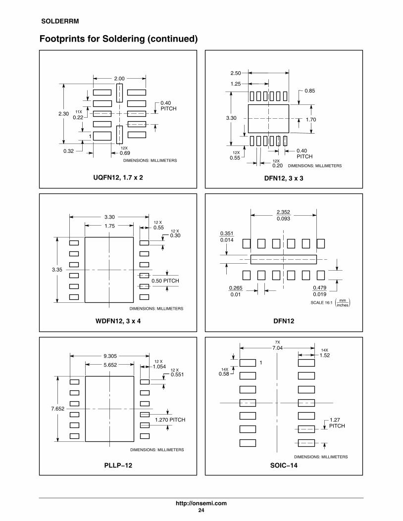
UQFN12, 1.7 x 2 24. . . . . . . . . . . . . . . . . DFN12, 3 x 3 24. . . . . . . . . . . . . . . . . . . . WDFN12, 3 x 4 24. . . . . . . . . . . . . . . . . .
DFN12 24. . . . . . . . . . . . . . . . . . . . . . . . . PLLP−12 24. . . . . . . . . . . . . . . . . . . . . . . . SOIC−14 24. . . . . . . . . . . . . . . . . . . . . . . .
TSSOP−14 25. . . . . . . . . . . . . . . . . . . . . . UQFN16/WQFN16, 1.8 x 2.6 25. . . . . . QFN−16, 3 x 3/EP, 2 x 2 25. . . . . . . . . .
QFN16, 4 x 4 25. . . . . . . . . . . . . . . . . . . . SOIC−16 25. . . . . . . . . . . . . . . . . . . . . . . . SOIC16−EP 25. . . . . . . . . . . . . . . . . . . . .
DFN16 26. . . . . . . . . . . . . . . . . . . . . . . . . TSSOP−16 26. . . . . . . . . . . . . . . . . . . . . . TSSOP−20 26. . . . . . . . . . . . . . . . . . . . . .
UDFN20, 4 x 2 26. . . . . . . . . . . . . . . . . . . LLGA−20, 6 x 5 26. . . . . . . . . . . . . . . . . . DFN22, 6 x 5 26. . . . . . . . . . . . . . . . . . . .
TLLGA32, 4 x 4 27. . . . . . . . . . . . . . . . . . QFN32, 5 x 5 27. . . . . . . . . . . . . . . . . . . . ChipFET 27. . . . . . . . . . . . . . . . . . . . . . . .
Board Level Application Notes for DFN and QFN Packages 29. . . . . . . . . . . . . . . . . . . . . . . . . . . . . . . . . . . . . . . Mounting Considerations for Power Semiconductors 34. . . . . . . . . . . . . . . . . . . . . . . . . . . . . . . . . . . . . . . . . . . . .
Section 3:Handling of Semiconductor Packages 62. . . . . . . . . . . . . . . . . . . . . . . . . . . . . . . . . . . . . . . . . . . . . . . . . . . . . . . . . . . .
Section 4:Semiconductor Package Reliability and Quality 69. . . . . . . . . . . . . . . . . . . . . . . . . . . . . . . . . . . . . . . . . . . . . . . . . . . .
Section 5:Device Rework / Removal 85. . . . . . . . . . . . . . . . . . . . . . . . . . . . . . . . . . . . . . . . . . . . . . . . . . . . . . . . . . . . . . . . . . . . . .

SOLDERRM
http://onsemi.com4

SOLDERRM
http://onsemi.com5
Section 1
General Pb (Lead) Free Lead Finish/Plating Strategy

SOLDERRM
http://onsemi.com6
General Pb (Lead) Free Lead Finish/Plating Strategy
In order to provide maximum flexibility and conveniencefor our customers, ON Semiconductor is modifying itsstrategy to support the Pb−free global initiatives from theprevious General Announcement #12770.
Pb−free Plating Strategy � ON Semiconductor nowoffers a portfolio of devices that are plated with Pb−freelead finishes. Many of our products were originallyreleased as Pb−free and do not have a comparable leadedversion available. For devices which have been Pb−freesince their inception, we do not intend to introduce anynew Pb−containing lead finish versions of those devices.
For those customers that choose not to convert to ourPb−free offering according to our conversion plan, ONSemiconductor will continue to offer the current Pbcontaining devices until business conditions no longerprove feasible. We are committed to meeting the needs ofall of our customers as our industry transitions to Pb−freeover the next couple of years.
ON Semiconductor has qualified the majority of ourpackages in the Pb−free version and have made themavailable for sampling and production ordering.
ON Semiconductor is fully compliant with the RoHSdirective for all of the parts for which it makes businesssense to do so. In other words, ON Semiconductor offersPb−free versions of all of the parts for which there issufficient demand. We will also continue to offer all ofthese parts in a standard Tin−Lead (SnPb) lead finish untilmarket conditions necessitate a change in direction.
Moisture Sensitivity Level (MSL) � Surface MountPackages are qualified to 260°C, which is compliant tothe JEDEC standard J−STD−020C. The majority of theMSL ratings will remain unchanged from the currentMSL 1 classification. If there is a change in the MSLrating of a package, the customer will be notified andappropriate packing precautions will be taken before anyproduct is shipped by ON Semiconductor.
Product Identification � Devices offered without aPb containing lead finish will be concatenated with a “G”suffix to denote Pb−free lead finish and qualifiedcompatibility with Pb−free board mount assemblyprocessing. Existing packages that are currently offered
solely with a Pb−free finish will also change partnumbers. This is intended to clearly identify parts that arePb−free and qualified for compatibility with Pb−freeboard mount assembly processing. The MPN(Manufacturer Part Number) bar code label on the reel,tube or rail, and the intermediate boxes will have the“Pb−free 2LI” logo printed on those labels compliant toJEDEC standard JESD97. Pb−free products may also beidentified by unique product marking. Pb−free productsare marked with a G suffix to the part number on thepackage. However, if the package is too small to includethe additional G character, the Pb−free package will bemarked with a micro dot.
Qualification Plan:The qualification requirements for Pb−free external
lead finish differ for surface−mount device (SMD) orthrough−hole devices (THD).
For the THDs the primary qualification requirement isto demonstrate forward compatibility with new Pb−freesolder pastes (based on SnCuAg). The tests performedtypically include:
• Solderability with SnCuAg solder
• Resistance to Solder Heat
For the SMDs reclassification of the moisturesensitivity level (MSL) at a peak reflow temperature of260°C is required in addition to solderability validation.The MSL reclassification is performed on the largestdie size that is used in the package. The tests performedtypically include:
• Preconditioned Highly Accelerated Stress Testing(PC−HAST) − 96 hours minimum
• Preconditioned Autoclave (PC−AC) − 96 hoursminimum
• Preconditioned Temperature Cycling (PC−TC) − 500cycles minimum
• (Preconditioning is performed at the target MSL for260 +5/−0°C)
• Solderability with SnCuAg solder• Resistance to Solder Heat (RSH − Solder Immersion)

SOLDERRM
http://onsemi.com7
Backward CompatibilityBackward compatibility is the capability for our
customers to take one of our Pb−free products, mount it ontheir PC board and reflow it using solder containing lead(Pb). ON Semiconductor has conducted reflow tests ofPb−free parts using leaded solder reflow temperatures andprocesses to simulate this condition. Tests have beenconducted at 210 to 230°C and results show that there willnot be solderability issues.
Please Note: This does not apply to BGA, bumped dieor Flip−Chip devices. If the parts are Pb−free theyneed to use a Pb−free reflow process.
Points of Contact:• Your Local ON Semiconductor Sales Representative
• ON Semiconductor Technical Information Center1−800−282−9855 (US & Canada) or via web athttp://www.onsemi.com/tech−support
• http://www.onsemi.com/pb−free

SOLDERRM
http://onsemi.com8

SOLDERRM
http://onsemi.com9
Section 2
Soldering / Mounting Techniques

SOLDERRM
http://onsemi.com10
Soldering Considerations for Surface Mount PackagesRECOMMENDED FOOTPRINTS FOR SURFACE MOUNTED APPLICATIONS
Surface mount board layout is a critical portion of the totaldesign. The footprint for the semiconductor packages mustbe the correct size to ensure proper solder connection
interface between the board and the package. With thecorrect pad geometry, the packages will self align whensubjected to a solder reflow process.
POWER DISSIPATION FOR A SURFACE MOUNT DEVICE
The power dissipation for a surface mount device is afunction of the drain/collector pad size. These can vary fromthe minimum pad size for soldering to a pad size given formaximum power dissipation. Power dissipation for asurface mount device is determined by TJ(max), themaximum rated junction temperature of the die, RθJA, thethermal resistance from the device junction to ambient, andthe operating ambient temperature, TA. Using the valuesprovided on the data sheet, PD can be calculated as follows:
PD =TJ(max) − TA
RθJA
The values for the equation are found in the maximumratings table on the data sheet. Substituting these values intothe equation for an ambient temperature TA of 25°C, one cancalculate the power dissipation of the device. For example,for a SOT−223 device, PD is calculated as follows.
PD = 150°C − 25°C156°C/W
= 800 milliwatts
The 156°C/W for the SOT−223 package assumes the useof the recommended footprint on a glass epoxy printedcircuit board to achieve a power dissipation of 800milliwatts. There are other alternatives to achieving higherpower dissipation from the surface mount packages. One isto increase the area of the drain/collector pad. By increasingthe area of the drain/collector pad, the power dissipation canbe increased. Although the power dissipation can almost bedoubled with this method, area is taken up on the printedcircuit board which can defeat the purpose of using surfacemount technology. For example, a graph of RθJA versusdrain pad area is shown in Figures 1, 2 and 3.
Another alternative would be to use a ceramic substrate oran aluminum core board such as Thermal Clad™. Using aboard material such as Thermal Clad, an aluminum coreboard, the power dissipation can be doubled using the samefootprint.
TO A
MBI
ENT
(C
/W)
°R
JA, T
HER
MAL
RES
ISTA
NC
E, J
UN
CTI
ON
θ
0.8 Watts
1.25 Watts* 1.5 Watts
A, AREA (SQUARE INCHES)0.0 0.2 0.4 0.6 0.8 1.0
160
140
120
100
80
Figure 1. Thermal Resistance versus Drain PadArea for the SOT−223 Package (Typical)
Board Material = 0.0625″G-10/FR-4, 2 oz Copper
TA = 25°C
*Mounted on the DPAK footprint
Figure 2. Thermal Resistance versus Drain PadArea for the DPAK Package (Typical)
1.75 Watts
Board Material = 0.0625″G-10/FR-4, 2 oz Copper
80
100
60
40
201086420
3.0 Watts
5.0 Watts
TA = 25°C
A, AREA (SQUARE INCHES)
TO A
MBI
ENT
(C
/W)
°R
JA, T
HER
MAL
RES
ISTA
NC
E, J
UN
CTI
ON
θ
Figure 3. Thermal Resistance versus Drain PadArea for the D2PAK Package (Typical)
2.5 Watts
A, AREA (SQUARE INCHES)
Board Material = 0.0625″G-10/FR-4, 2 oz Copper TA = 25°C
60
70
50
40
30
201614121086420
3.5 Watts
5 Watts
TO A
MBI
ENT
(C
/W)
°R
JA, T
HER
MAL
RES
ISTA
NC
E, J
UN
CTI
ON
θ

SOLDERRM
http://onsemi.com11
SOLDER STENCIL GUIDELINES
Prior to placing surface mount components onto a printedcircuit board, solder paste must be applied to the pads.Solder stencils are used to screen the optimum amount.These stencils are typically 0.008 inches thick and may bemade of brass or stainless steel. For packages such as theSC−59, SC−70/SOT−323, SOD−123, SOT−23, SOT−143,SOT−223, SO−8, SO−14, SO−16, and SMB/SMC diodepackages, the stencil opening should be the same as the padsize or a 1:1 registration. This is not the case with the DPAKand D2PAK packages. If a 1:1 opening is used to screensolder onto the drain pad, misalignment and/or“tombstoning” may occur due to an excess of solder. Forthese two packages, the opening in the stencil for the pasteshould be approximately 50% of the tab area. The openingfor the leads is still a 1:1 registration. Figure 4 shows atypical stencil for the DPAK and D2PAK packages. The
pattern of the opening in the stencil for the drain pad is notcritical as long as it allows approximately 50% of the pad tobe covered with paste.
ÇÇÇÇÇÇÇÇ
ÇÇÇÇÇÇÇÇÇÇÇÇ
ÇÇÇÇÇÇ
ÇÇÇÇÇÇ
ÇÇÇÇ
Figure 4. Typical Stencil for DPAK andD2PAK Packages
SOLDER PASTEOPENINGS
STENCIL
SOLDERING PRECAUTIONS
The melting temperature of solder is higher than the ratedtemperature of the device. When the entire device is heatedto a high temperature, failure to complete soldering withina short time could result in device failure. Therefore, thefollowing items should always be observed in order tominimize the thermal stress to which the devices aresubjected.
• Always preheat the device.• The delta temperature between the preheat and
soldering should be 100°C or less.*• When preheating and soldering, the temperature of the
leads and the case must not exceed the maximumtemperature ratings as shown on the data sheet. Whenusing infrared heating with the reflow solderingmethod, the difference should be a maximum of 10°C.
• The soldering temperature and time should not exceed260°C for more than 10 seconds.
• When shifting from preheating to soldering, themaximum temperature gradient shall be 5°C or less.
• After soldering has been completed, the device shouldbe allowed to cool naturally for at least three minutes.Gradual cooling should be used since the use of forcedcooling will increase the temperature gradient and willresult in latent failure due to mechanical stress.
• Mechanical stress or shock should not be applied duringcooling.
* Soldering a device without preheating can causeexcessive thermal shock and stress which can result indamage to the device.
* Due to shadowing and the inability to set the wave heightto incorporate other surface mount components, the D2PAKis not recommended for wave soldering.

SOLDERRM
http://onsemi.com12
TYPICAL SOLDER HEATING PROFILE
For any given circuit board, there will be a group ofcontrol settings that will give the desired heat pattern. Theoperator must set temperatures for several heating zones anda figure for belt speed. Taken together, these control settingsmake up a heating “profile” for that particular circuit board.On machines controlled by a computer, the computerremembers these profiles from one operating session to thenext. Figure 5 shows a typical heating profile for use whensoldering a surface mount device to a printed circuit board.This profile will vary among soldering systems, but it is agood starting point. Factors that can affect the profileinclude the type of soldering system in use, density and typesof components on the board, type of solder used, and the typeof board or substrate material being used. This profile showstemperature versus time. The line on the graph shows the
actual temperature that might be experienced on the surfaceof a test board at or near a central solder joint. The twoprofiles are based on a high density and a low density board.The Vitronics SMD310 convection/infrared reflowsoldering system was used to generate this profile. The typeof solder used was 62/36/2 Tin Lead Silver with a meltingpoint between 177−189°C. When this type of furnace is usedfor solder reflow work, the circuit boards and solder jointstend to heat first. The components on the board are thenheated by conduction. The circuit board, because it has alarge surface area, absorbs the thermal energy moreefficiently, then distributes this energy to the components.Because of this effect, the main body of a component maybe up to 30 degrees cooler than the adjacent solder joints.
STEP 1PREHEATZONE 1“RAMP”
STEP 2VENT
“SOAK”
STEP 3HEATING
ZONES 2 & 5“RAMP”
STEP 4HEATING
ZONES 3 & 6“SOAK”
STEP 5HEATING
ZONES 4 & 7“SPIKE”
STEP 6VENT
STEP 7COOLING
200°C
150°C
100°C
5°C
TIME (3 TO 7 MINUTES TOTAL) TMAX
SOLDER IS LIQUID FOR40 TO 80 SECONDS
(DEPENDING ONMASS OF ASSEMBLY)
205° TO 219°CPEAK ATSOLDER
JOINT
DESIRED CURVE FOR LOWMASS ASSEMBLIES
DESIRED CURVE FOR HIGHMASS ASSEMBLIES
100°C
150°C160°C
170°C
140°C
Figure 5. Typical Tin Lead (SnPb) Solder Heating Profile

SOLDERRM
http://onsemi.com13
Figure 6. Typical Pb−Free Solder Heating Profile
RAMP−UP
25
tSPreheat
Critical ZoneTL to Tp
tp
TL
TE
MP
ER
AT
UR
E ⇒
TIME ⇒
Tp
Tsmax
Tsmin
t 25°C to Peak
tL
RAMP−DOWN
Profile Feature Pb−Free Assembly
Average Ramp−Up Rate (Tsmax to Tp) 3°C/second max
Preheat Temperature Min (Tsmin) Temperature Max (Tsmax) Time (tsmin to tsmax)
150°C200°C
60−180 seconds
Time maintained above Temperature (TT) Time (tT)
217°C60−150 seconds
Peak Classification Temperature (Tp) 260°C +5/−0
Time within 5°C of actual Peak Temperature (tp) 20−40 seconds
Ramp−Down Rate 6°C/second max
Time 25°C to Peak Temperature 8 minutes max

SOLDERRM
http://onsemi.com14
Footprints for Soldering
POWERMITE�
2.540.100
0.6350.025
1.270.050
2.670.105 0.762
0.030
� mminches
�SCALE 10:1
SMA
4.00.157
2.00.0787
2.00.0787
� mminches
�SCALE 8:1
SMB
� mminches
�SCALE 8:1
2.7430.108
2.1590.085
2.2610.089
SMC
4.3430.171
2.7940.110
3.8100.150
� mminches
�SCALE 4:1
1.600.063
1.220.048
0.630.025
� mminches
�SCALE 10:1
SOD−123
ÉÉÉÉÉÉ
0.910.036
2.360.0934.190.165
SOD−323
� mminches
�SCALE 10:1
ÉÉÉÉÉÉ
0.830.033
2.850.112

SOLDERRM
http://onsemi.com15
Footprints for Soldering (continued)
0.400.0157
0.400.0157
1.400.0547
� mminches
�SCALE 10:1
SOD−523
0.450.0177
0.500.0197
1.10.043
� mminches
�SCALE 10:1
SOD−723
SC−59
2.40.094
0.950.037
0.950.037
1.00.039
0.80.031
� mminches
�SCALE 10:1
SC−70/SOT−323
1.90.075
0.650.025
0.650.025
0.90.035
0.70.028
� mminches
�SCALE 10:1
SC−75/SC−89/SOT−416
� mminches
�SCALE 10:1
0.80.031
0.90.035
0.950.0370.95
0.037
SOT−23
2.00.079
0.7870.031
0.5080.020 1.000
0.039
� mminches
�SCALE 10:1
0.3560.014
1.8030.071

SOLDERRM
http://onsemi.com16
Footprints for Soldering (continued)
SOT−723
1.00.039
� mminches
�SCALE 20:1
0.400.0157
0.400.0157
0.400.0157
0.400.0157
0.400.0157
SOT−1123
0.40
0.30
0.90
DIMENSIONS: MILLIMETERS
0.35
0.25
D2PAK
8.380.33
1.0160.04
17.020.67
10.660.42
3.050.12
5.080.20
� mminches
�SCALE 3:1
DPAK
5.800.228
2.580.101
1.60.063
6.200.244
3.00.118
6.1720.243
� mminches
�SCALE 3:1
1.300.512
� mminches
�SCALE 10:1
0.650.026
1.900.075
0.900.035
0.700.028
0.950.037
SC−82ABWDFN3
0.600
1.300
0.300
0.250
0.400
1.600
1.100
0.4002X
0.275
DIMENSIONS: MILLIMETERS

SOLDERRM
http://onsemi.com17
Footprints for Soldering (continued)
1.350.0531
0.50.0197
� mminches
�SCALE 20:1
0.50.0197
1.00.0394
0.450.0177
0.30.0118
SOT−5531.5
0.059SOT−223
� mminches
�SCALE 6:1
3.80.15
2.00.079
6.30.248
2.30.091
2.30.091
2.00.079
0.350.014
0.200.08
� mminches
�SCALE 20:1
SOT−953
0.900.0354
0.350.014
0.200.08� mm
inches�SCALE 20:1
0.650.025
0.650.025
0.500.0197
0.400.0157
1.90.0748
SC−88A/SC70−5/SOT−353
8.380.33
1.0160.04
16.020.63
10.660.42
3.050.12
1.7020.067
5−LEAD D2PAK
SCALE 3:1 � mminches
�
THIN SOT23−5/TSOP−5/SC59−5
0.70.028
1.00.039
� mminches
�SCALE 10:1
0.950.037
2.40.094
1.90.074

SOLDERRM
http://onsemi.com18
Footprints for Soldering (continued)
6 PIN FLIP−CHIP(1.00 x 1.50 mm, 0.5 Pitch)
SCALE 20:1 � mminches
�
1.00.0394
0.5000.0197
0.5000.0197
0.250 − 0.2750.0098 − 0.0108
6.40.252
0.80.031
10.60.417
5.80.228
5−LEAD DPAK CENTRAL LEAD CROP
SCALE 4:1 � mminches
�
0.340.013
5.360.217
2.20.086
SC−74/SC−74R
0.70.028
1.90.074
0.950.037
2.40.094
1.00.039
0.950.037
� mminches
�SCALE 10:1
SC−88/SC70−6/SOT−363
� mminches
�SCALE 20:1
0.650.025
0.650.025
0.500.0197
0.400.0157
1.90.0748
0.350.014
0.200.08
� mminches
�SCALE 20:1
SOT−963
0.900.0354
0.350.014
0.200.08
1.350.0531
0.50.0197
� mminches
�SCALE 20:1
0.50.0197
1.00.0394
0.450.0177
0.30.0118
SOT−563

SOLDERRM
http://onsemi.com19
Footprints for Soldering (continued)
UDFN6/WDFN6, 1.2 x 1
� mminches
�
1.2990.0511
0.4000.0157
1.1240.0443
1.2120.0477
0.5750.0226
0.3240.0128
0.6500.0256
6X
PITCH
5X
0.950.037
1.90.075
� mminches
�SCALE 10:1
1.00.039
TSOP−6
2.40.094
0.70.028
0.950.037
DFN6, 2 x 2.2
0.500.020
� mminches
�SCALE 10:1
0.400.016
1.90.075
0.650.025
0.650.025
0.500.020
� mminches
�DFN6, 2 x 2
0.3250.0128
6X
0.6500.0256
0.4750.0187
1.1000.0433
2.3000.0906
0.7700.0303
0.7700.0303
0.2000.0079
6X
PITCH
3.310.130
0.630.025
2.600.1023
0.4500.0177
1.7000.685
� mminches
�SCALE 10:1
0.9500.0374
DFN6, 3 x 3, Single Flag
ÇÇÇÇ
ÇÇÇÇ
ÇÇ
ÇÇÇÇ
ÇÇÇÇ
ÇÇ
3.310.130
0.630.025 0.65
0.025
0.350.014
2.450.964
1.7000.685
Exposed PadSMD Defined
DFN6, 3 x 3, Single Flag
� mminches
�SCALE 10:1

SOLDERRM
http://onsemi.com20
Footprints for Soldering (continued)
CLCC−6, 7 x 5 mm
PITCH2.54
1.506X
5.06
1.506X
DIMENSION: MILLIMETERS
DFN6, 3 x 3, Dual Flag
3.310.130
0.630.025 1.20
0.0472
0.350.014
0.4500.0177
1.7000.685
� mminches
�SCALE 10:1
0.9500.0374
0.8500.0334
8.260.325
10.540.415
0.960.038
7−LEAD D2PAK, SHORT LEAD
SCALE 3:1 � mminches
�
9.50.374
3.250.128
2.160.085
3.80.150
1.270.050
CL
CL
1
8.890.350MIN
15.460.609MIN
11.430.450MIN
1.270.050
7−LEAD D2PAK
0.760.030TYP3.27
0.129TYP
SCALE 3:1 � mminches
�
Micro8�
8X 8X
6X � mminches
�SCALE 8:1
1.040.041
0.380.015
5.280.208
4.240.167
3.200.126
0.650.0256
Micro8 Leadless
2.75
1.50
0.33
8X
3.60
1.23
0.65 PITCH
0.58
8X
0.40
DIMENSIONS: MILLIMETERS

SOLDERRM
http://onsemi.com21
Footprints for Soldering (continued)
SO−8
1.520.060
7.00.275
0.60.024
1.2700.050
4.00.155
� mminches
�SCALE 6:1
ExposedPad
SO−8Exposed Pad
1.520.060
2.030.08
0.60.024
1.2700.050
4.00.155
� mminches
�SCALE 6:1
7.00.275
2.720.107
SO8FL (DFN6), 5 x 6
1.270
2X
0.750
1.000
0.905
0.475
4.530
1.530
4.560
0.495
3.200
1.330
0.965
2X
2X
3X 4X
4X
DIMENSIONS: MILLIMETERS
DFN8/UDFN8, 1.6 x 1.6
� mminches
�SCALE 20:1
0.9020.0355
0.9240.0364
0.4900.0193
0.4000.0157PITCH
0.5020.0197
0.2000.0079
DFN8, 2 x 2UDFN8, 1.8 x 1.2
� mminches
�SCALE 15:1
1.3500.0531
1.1500.0453
0.5750.0226
0.5000.0197PITCH
0.7000.0276
0.3000.0118
0.2500.0098
0.22
0.32
8X
1.50
0.40 PITCH
0.66
DIMENSIONS: MILLIMETERS
7X
1

SOLDERRM
http://onsemi.com22
Footprints for Soldering (continued)
UDFN8, 2 x 2.2 DFN8, 3 x 3
ÇÇÇÇÇÇÇÇÇÇÇÇ
ÇÇÇÇÇÇÇÇÇÇÇÇÇÇÇÇÇÇ
8X0.48
1.60
0.80
10.25
0.50PITCH
2.15
8X
DIMENSIONS: MILLIMETERS
ÇÇÇÇÇÇÇÇÇÇÇÇÇÇÇÇÇÇÇÇÇÇÇÇ
ÇÇÇÇÇÇÇÇÇÇÇÇÇÇÇÇ 8X
0.52
2.55
1.80
0.351
0.65PITCH
3.30
1.10
8X
DIMENSIONS: MILLIMETERS
1.28 1.15
DFN8, 5 x 6DFN8, 4 x 4
DIMENSIONS: MILLIMETERS
ÇÇÇÇÇÇÇÇÇÇÇÇÇÇÇÇ
ÇÇÇÇÇÇÇÇÇÇÇÇÇÇÇÇ
8X
0.632.21
2.39
2.75
1
8X
0.40
0.80PITCH
4.30
0.35
4.20
3.20
1.27 PITCH0.958X
6.30
DIMENSIONS: MILLIMETERS
0.64
0.718X
1
US8
� mminches
�SCALE 8:1
3.80.15
0.500.0197
1.00.0394
0.300.012
1.80.07
� mminches
�SCALE 20:1
0.2650.01
0.500.0197
0.500.0197
8−Bump(Flip−Chip)
DIE SIZE MAY VARY

SOLDERRM
http://onsemi.com23
Footprints for Soldering (continued)
� mminches
�SCALE 20:1
0.2650.01
0.500.0197
0.500.0197
9−Bump(1.550 x 1.550 mm)
� mminches
�SCALE 8:1
Micro10
10X 10X
8X
1.040.041
0.320.0126
5.280.208
4.240.167
3.200.126
0.500.0196
UQFN10/WQFN10, 1.4 x 1.8 mm
10 XPITCH
1
9 X
SCALE 20:1
0.6630.0261
0.2000.0079
0.4000.0157
0.2250.0089
1.7000.0669
1.7000.0669 0.225
0.0089
� mminches
�
WDFN10, 2.5 x 2 mm
1.13
2.50
0.50
0.05
0.73
10X
DIMENSIONS: MILLIMETERS
0.580.95
PITCH
0.30
10X
UDFN10
2.1746
2.6016
1.8508
0.5000 PITCH
0.565110X
3.3048
0.300810X
DIMENSIONS: MILLIMETERS
0.2800.011
� mminches
�SCALE 10:1
0.6300.025
DFN10, 3 x 3 mm
2.500.098
3.310.130
1.650.065
0.5000.0196
SOLDERRM
http://onsemi.com24
Footprints for Soldering (continued)
DFN12, 3 x 3UQFN12, 1.7 x 2
0.32
11X2.30
0.69
0.40
DIMENSIONS: MILLIMETERS
1
0.22
2.00
PITCH
12X
3.30
2.50
1.70
0.400.55
12X
0.85
0.2012X
DIMENSIONS: MILLIMETERS
1.25
PITCH
WDFN12, 3 x 4
3.3012 X
1.75 0.5512 X0.30
3.35
0.50 PITCH
DIMENSIONS: MILLIMETERS
DFN12
2.3520.093
� mminches
�SCALE 16:1
0.2650.01
0.4790.019
0.3510.014
PLLP−12
9.30512 X
5.652 1.05412 X0.551
7.652
1.270 PITCH
DIMENSIONS: MILLIMETERS
SOIC−14
7.04
14X0.58
14X1.52
1.27
DIMENSIONS: MILLIMETERS
1
PITCH
7X

SOLDERRM
http://onsemi.com25
Footprints for Soldering (continued)
TSSOP−14
7.06
14X0.36 14X
1.26
0.65
DIMENSIONS: MILLIMETERS
1
PITCH
� mminches
�SCALE 20:1
UQFN16/WQFN16, 1.8 x 2.6 mm
1
0.4000.0157
0.2250.0089
0.4630.0182
0.5620.0221
2.9000.1142
1.2000.0472
2.1000.0827
� mminches
�SCALE 10:1
0.500.02
0.5750.022
1.500.059
3.250.128
0.300.012
3.250.128
0.300.012
EXPOSED PAD
QFN−16, 3 x 3 mm,EP 2 x 2 mm QFN16, 4 x 4 mm
4.30
1
0.50
DIMENSIONS: MILLIMETERS
2.80 4.30
2.80
0.40
0.65
16X
16X
PITCH
SOIC−16
6.40
16X0.58
16X 1.12
1.27
DIMENSIONS: MILLIMETERS
1
PITCH
16
8 9
8X
SOIC16−EP
0.350
0.175
0.050
0.376
0.188
0.200
0.074
DIMENSIONS: INCHES
0.024 0.145
ExposedPad
CL
CL

SOLDERRM
http://onsemi.com26
Footprints for Soldering (continued)
DFN16
0.50
4.10
0.50 PITCH14X
DIMENSIONS: MILLIMETERS
1.91
0.5116X0.2816X
TSSOP−16
7.06
16X0.36 16X
1.26
0.65
DIMENSIONS: MILLIMETERS
1
PITCH
TSSOP−20
7.06
16X0.36 16X
1.26
0.65
DIMENSIONS: MILLIMETERS
1
PITCH
UDFN20, 4 x 2
0.22
0.88
19X
2.30
0.40 PITCH
0.78
DIMENSIONS: MILLIMETERS
20X
1
LLGA−20, 6 x 5
4.05
2.10
0.80
19X0.35
1.95
4.60
DIMENSIONS: MILLIMETERS
1
3.70
3.10
20X 0.35
PITCH
1.200.45
0.80PITCH
0.35
0.25
2.63
DFN22, 6 x 5 mm
0.2800.011
� mminches
�SCALE 8:1
0.9800.039
4.3000.169
5.7700.227
3.1300.123
0.5000.020
0.3400.013
20X 22X

SOLDERRM
http://onsemi.com27
Footprints for Soldering (continued)
DIMENSIONS: MILLIMETERS
QFN32, 5 x 5 mm
0.50 PITCH
3.20
0.28
3.20
32 X28 X
0.6332 X
5.30
5.30
TLLGA32, 4 x 4
32X
0.30
0.40PITCH
4.60
0.63
2.94
1
DIMENSIONS: MILLIMETERS
0.2031X
2X
2X
Basic
ChipFET
0.4570.018
2.0320.08
0.6350.025PITCH
0.660.026
� mminches
�
2.3620.093
1
8X
8X

SOLDERRM
http://onsemi.com28
Footprints for Soldering (continued)
Styles 1 and 4
ChipFET (continued)
2.0320.08
1.7270.068
0.660.026
2.3620.093
� mminches
�0.4570.018
1
2X
2X
0.4570.018
2.0320.08
0.6350.025PITCH
0.660.026
1.1180.044 � mm
inches�
1.0920.043
2.3620.093
Style 2
1
2X4X
2X
4X
Style 5
0.4570.018
2.0320.08
0.660.026
1.1180.044
� mminches
�
1.0920.043
Style 3
1
2X
2X
0.6350.025PITCH
2.3620.093
0.4570.018
2.0320.08
0.660.026
1.1180.044
� mminches
�
1.0920.043
1
2X
2X
0.6350.025PITCH
2.3620.093

SOLDERRM
http://onsemi.com29
AND8211/D
Board Level ApplicationNotes for DFN and QFNPackages
INTRODUCTION
Various ON Semiconductor components are packaged inan advanced Dual or Quad Flat−Pack No−Lead package(DFN/QFN). The DFN/QFN platform represents the latestin surface mount packaging technology. It is important tofollow the suggested board mounting guidelines outlined inthis document. These guidelines include printed circuitboard mounting pads, solder mask and stencil pattern andassembly process parameters.
DFN/QFN Package OverviewThe DFN/QFN platform offers a versatility which allows
either a single or multiple semiconductor devices to beconnected together within a leadless package. Thispackaging flexibility is illustrated in Figure 7 where threedevices are packaged together with a custom padconfiguration in a QFN.
Figure 7. Underside of a Three−Chip 40 PinQFN Package
Figure 8 illustrates a DFN semiconductor device packagewhich allows for a single device.
Figure 8. Underside of a Single−Chip 8 PinDFN Package
Figure 9 illustrates how the package height is reduced toa minimum by having both the die and wirebond pads on thesame plane. When mounted, the leads are directly attachedto the board without a space−consuming standoff, which isinherent in a leaded package.
Figure 9 also illustrates how the ends of the leads are flushwith the edge of the package. This configuration allows formaximizing the board space efficiency.
WirebondDie
Leadframe
Figure 9. Cross−Section of a Single−ChipDFN Package
In addition to these features, the DFN/QFN package hasexcellent thermal dissipation and reduced electricalparasitics due to its efficient and compact design.
APPLICATION NOTE
http://onsemi.com

SOLDERRM
http://onsemi.com30
DFN/QFN Board Mounting ProcessThe DFN/QFN board mounting process can be optimized
by first defining and controlling the following:
1. PCB solder pad design.2. PCB solder mask design.3. Solderable metallization on PCB pads.4. Solder screening onto PCB pads.5. Choice of solder paste.6. Package placement.7. Reflow of the solder paste.8. Final inspection of the solder joints.
Recommendations for each of these items are included inthis application note.
Printed Circuit Board Solder Pad DesignGuidelines
Refer to the case outline (specification sheet) drawing forthe specific DFN/QFN package to be mounted. Based on thecase outline’s “nominal” package footprint dimensions, thePCB mounting pads need to be larger than the nominalpackage footprint (See Figure 10).
Note: On the occasion that there is not enough board spaceto grow the PCB mounting pads per these guidelines, therecommendation would be to come as close to theseguidelines as possible.
Figure 10. 10 Pin DFN Package Footprint Shownwith PCB Mounting Pads
Package FootprintPCB Mounting Pads
Color LegendFor PCB Mounting Pads used in Figure 4
Printed Circuit Board Solder Mask DesignGuidelines
SMD and NSMD Pad ConfigurationsTwo types of PCB solder mask openings commonly used
for surface mount leadless style packages are:1. Non Solder Masked Defined (NSMD)2. Solder Masked Defined (SMD)
NSMD SMD
Solder Mask Opening
Solder MaskOverlay
SolderablePCB Pad
Figure 11. Comparison of NSMD vs. SMD Pads
As their titles describe, the NSMD contact pads have thesolder mask pulled away from the solderable metallization,while the SMD pads have the solder mask over the edge ofthe metallization, as shown in Figure 11. With the SMDPads, the solder mask restricts the flow of solder paste on thetop of the metallization which prevents the solder fromflowing along the side of the metal pad. This is differentfrom the NSMD configuration where the solder will flowaround both the top and the sides of the metallization.
Typically, the NSMD pads are preferred over the SMDconfiguration since defining the location and size of thecopper pad is easier to control than the solder mask. This isbased on the fact that the copper etching process is capableof a tighter tolerance than the solder masking process. Thisalso allows for visual inspection of solder fillet.
In addition, the SMD pads will inherently create a stressconcentration point where the solder wets to the pad on topof the lead. This stress concentration point is reduced whenthe solder is allowed to flow down the sides of the leads inthe NSMD configuration.
When dimensionally possible, the solder mask shouldbe located within a range of 0.0762–0.1270 mm(0.003–0.005 in) away from the edge of the PCB mountingpad (See Figure 12). This spacing is used to compensate forthe registration tolerances of the solder mask process, aswell as to insure that the solder is not inhibited by the maskas it reflows along the sides of the metal pad.

SOLDERRM
http://onsemi.com31
The solder mask web (between openings) is thecontrolling factor in the pattern, and needs to be held to aminimum of 0.1016 mm (0.004 in). This minimum is thecurrent PCB suppliers standard minimum web formanufacturability. Because of this web restriction, soldermask openings around PCB pads may need to be less thanthe recommended shown. Whenever possible, keeping tothe range given will provide for the best results.
Due to ever shrinking packages with finer pitches betweenmounting pads, a solder mask web may not be possible. Itmay be necessary to have a single solder mask windowopening around the package without solder mask webbetween mounting pads. When this occurs, care must betaken to control the solder during reflow. Where the webaided in controlling the solder, in its absence, solder maybridge between mounting pads causing shorts.
Figure 12. Typical DFN Package − PCB MountingPads Shown with Solder Mask Openings (NSMD)
Solder Mask OpeningsPCB Mounting Pads
Color LegendFor PCB Mounting Pads used in Figure 6
PCB Solderable MetallizationThere are currently three common solderable coatings
which are used for PCB surface mount devices − OSP,ENiAu and HASL. In any case, it is imperative that thecoating is uniform, conforming, and free of impurities toinsure a consistant solderable system.
The first coating consists of an Organic SolderabilityProtectant (OSP) applied over the bare copper feature. OSPcoating assists in reducing oxidation in order to preserve the
copper metallization for soldering. It allows for multiplepasses through reflow ovens without degradation of thesolderability. The OSP coating is dissolved by the flux whenthe solder paste is applied to the metal features. Coatingthickness recommended by OSP manufacturers is between0.25 and 0.35 microns.
The second coating is plated electroless nickel/immersiongold over the copper pad. The thickness of the electrolessnickel layer is determined by the allowable internal materialstresses and the temperature excursions the board will besubjected to throughout its lifetime. Even though the goldmetallization is typically a self−limiting process, thethickness should be at least 0.05 microns thick, but notconsist of more than 5% of the overall solder volume.Excessive gold in the solder joint can create goldembrittlement. This may affect the reliability of the joint.
The third PCB pad protective coating option is Hot AirSolder Level (HASL); SnPb. Since the HASL process is notcapable of producing solder joints with consistent height,this pad finish is not recommended for DFN/QFN typepackages. Inconsistent solder deposition results indome-shaped pads of varying height. As the industry movesto finer and finer pitch, solder bridging between mountingpads becomes a common problem with this coating.
Solder Screening onto the PCBStencil screening the solder paste onto the PCB is
commonly used in the industry. The recommended stencilthickness used is 0.075 mm to 0.127 mm (0.003 in to0.005 in). The sidewalls of the stencil openings should betapered approximately 5° along with an electro−polishfinish to aid in the release of the paste when the stencil isremoved from the PCB.
On a typical 0.5 mm pitch or larger DFN/QFN the stencilopening for the perimeter pattern should be the same size asthe PCB mounting Pad. The center stencil opening for thecenter mounting pad(s) should allow for 70-80% coverageof the center mounting pad(s). (See Figure 13.) Dividing thelarger die pads into smaller screen openings reduces the riskof solder voiding and allows the solder joints for the smallerterminal pads to be at the same height as the larger ones.
On less than a 0.5 mm pitch DFN/QFN the stencil openingfor the perimeter pattern should be the same size as thedevice nominal footprint. The center stencil opening for thecenter mounting pad(s) should allow for 60-70% coverageof the center mounting pad(s). (See Figure 14.) Dividing thelarger die pads into smaller screen openings reduces the riskof solder voiding and allows the solder joints for the smallerterminal pads to be at the same height as the larger ones.

SOLDERRM
http://onsemi.com32
Figure 13. Typical for 0.5 mm Pitch or GreaterDFN/QFN Package with Stencil Openings Shown
Over PCB Mounting Pads
Package OutlinePCB Center Mounting PadsStencil Opening
Color LegendFor Stencil Openings used in Figure 7 and 8.
Figure 14. Typical Less than 0.5 mm Pitch DFN/QFNPackage with Stencil Openings Shown Over PCB
Mounting Pads
Solder PasteSolder paste such as Cookson Electronics’ WS3060 with
a Type 3 or smaller sphere size is recommended. TheWS3060 has a water−soluble flux for cleaning. CooksonElectronics’ PNC0106A can be used if a no−clean flux ispreferred.
Package Placement onto the PCBAn automated pick and place procedure with
magnification is recommended for component placement
since the pads are on the underside of these packages. A duelimage optical system enables alignment of the underside ofthe package to the PCB and should be used. Pick and placeequipment with the standard tolerance of ±0.05 mm(0.002 in) or better is recommended. Once placed onto theboard, the package self−aligns during the reflow process dueto surface tension of the solder.
Solder ReflowOnce the component is placed on the PCB, a standard
surface mount reflow process can be used to mount the part.Figures 15 and 16 are examples of typical reflow profiles forlead free and standard eutectic tin lead solder alloys,respectively.
The preferred profile is provided by the solder pastemanufacturer and is dictated by variations in chemistry andviscosity of the flux matrix in the solder paste. Thesevariations may require small adjustments to the profile forprocess optimization.
In general, the temperature of the part should increase byless than 2°C/sec during the initial stages of reflow. The soakzone occurs at approximately 150°C and should last for 60to 180 seconds for lead free profiles (30−120 sec for eutectictin lead profiles). Typically, extending the length of time inthe soak zone reduces the risk of voiding within the solder.The temperature is then increased. Time above the liquidusof the solder is limited to 60 to 150 seconds for lead freeprofiles (30−100 sec for eutectic tin lead profiles) dependingon the mass of the board. The peak temperature of the profileshould be between 245°C and 260°C for lead free solderalloys (205°C and 225°C for eutectic tin lead solders).
If required, removal of the residual solder flux can be doneusing the recommended procedures set forth by the fluxmanufacturer.
Figure 15. Typical Reflow Profile for Lead FreeSolder
Peak of 260°CTemperature (°C)
Lessthan 2°C/sec
SoakZone
60−180sec
Timeabove
liquidus
60−150sec
Time (sec)42531420494
300
250
200
150
100
50
0

SOLDERRM
http://onsemi.com33
Figure 16. Typical Reflow Profile for Eutectic Tin /Lead Solder
0
50
100
150
200
0 100 200 300 400 500
Time (sec)
SoakZone
Peak of 225°C
Less than2°C/sec
183
Temperature (°C)250
30 to 120 sec
TimeAbove
Liquidus
Final Solder InspectionSolder joint integrity is determined by using an X-ray
inspection system. With this tool, defects such as shortsbetween pads, open contacts, and voids within the solder andextraneous solder can be identified. In addition, the mounteddevice should be rotated on its side to inspect the side of thesolder joints for acceptable solder joint shape and stand-offheight. The solder joints should have enough solder volumeand stand−off height so that an “Hour Glass” shapedconnection is not formed as shown in Figure 17. “HourGlass” solder joints are a reliability concern and should beavoided.
PCB
PreferredSolder Joint
Undesirable“Hour Glass’’Solder Joint
Figure 17. Illustration of Preferred and UndesirableSolder Joints
Rework ProcedureSince the DFN/QFN’s are leadless devices, the package
must be removed from the PCB if there is an issue with thesolder joints.
Standard SMT rework systems are recommended for thisprocedure since airflow and temperature gradients can becarefully controlled. It is also recommended that the PCB beplaced in an oven at 125°C for 4 to 8 hours prior to packageremoval to remove excess moisture from the packages. Inorder to control the region which will be exposed to reflowtemperatures, the PCB should be heated to 100�C byconduction through the backside of the board in the locationof the device. Typically, heating nozzles are then used toincrease the temperature locally and minimize any chance ofoverheating neighboring devices in close proximity.
Once the device’s solder joints are heated above theirliquidus temperature, the package is quickly removed andthe pads on the PCB are cleaned. The cleaning of the padsis typically performed with a blade−style conductive toolwith a de−soldering braid. A no clean flux is used during thisprocess in order to simplify the procedure.
Solder paste is then deposited or screened onto the site inpreparation of mounting a new device. Due to the closeproximity of the neighboring packages in most PCBconfigurations, a miniature stencil for the individualcomponent is typically required. The same stencil designthat was originally used to mount the package can be appliedto this new stencil for redressing the pads.
Due to the small pad configurations of the DFN/QFN, andsince the pads are on the underside of the package, a manualpick and place procedure with the aid of magnification isrecommended. A system with the same capabilities asdescribed in the Package Placement section should be used.
Remounting the component onto the PCB can beaccomplished by either passing it through the originalreflow profile, or by selectively heating the specific regionon the PCB using the same process used to remove thedefective package. The benefit of subjecting the entire PCBto a second reflow is that the new part will be mountedconsistently using a previously defined profile. Thedisadvantage is that all of the other soldered device will bereflowed a second time. If subjecting all of the parts to asecond reflow is either a concern or unacceptable for aspecific application, then the localized reflow option is therecommended procedure.
Optimal board mounting results can be achieved byfollowing these suggested guidelines.

SOLDERRM
http://onsemi.com34
AN1040/D
Mounting Considerationsfor Power SemiconductorsPrepared by: Bill Roehr
INTRODUCTIONCurrent and power ratings of semiconductors are
inseparably linked to their thermal environment. Except forlead−mounted parts used at low currents, a heat exchangeris required to prevent the junction temperature fromexceeding its rated limit, thereby running the risk of a highfailure rate. Furthermore, the semiconductor industry’sfield history indicated that the failure rate of most siliconsemiconductors decreases approximately by one−half for adecrease in junction temperature from 160°C to 135°C.(1)
Guidelines for designers of military power supplies imposea 110°C limit upon junction temperature.(2) Propermounting minimizes the temperature gradient between thesemiconductor case and the heat exchanger.
Most early life field failures of power semiconductorscan be traced to faulty mounting procedures. With metalpackaged devices, faulty mounting generally causesunnecessarily high junction temperature, resulting inreduced component lifetime, although mechanical damagehas occurred on occasion from improperly mounting to awarped surface. With the widespread use of variousplastic−packaged semiconductors, the prospect ofmechanical damage is very significant. Mechanicaldamage can impair the case moisture resistance or crackthe semiconductor die.
Figure 18 shows an example of doing nearly everythingwrong. A tab mount TO−220 package is shown being usedas a replacement for a TO−213AA (TO−66) part which wassocket mounted. To use the socket, the leads are bent − anoperation which, if not properly done, can crack thepackage, break the internal bonding wires, or crack the die.The package is fastened with a sheet−metal screw througha 1/4″ hole containing a fiber−insulating sleeve. The forceused to tighten the screw tends to pull the package into thehole, possibly causing enough distortion to crack the die. Inaddition the contact area is small because of the areaconsumed by the large hole and the bowing of the package;the result is a much higher junction temperature thanexpected. If a rough heatsink surface and/or burrs aroundthe hole were displayed in the illustration, most but not allpoor mounting practices would be covered.
PLASTIC BODY
PACKAGE HEATSINK
MICA WASHER
SPEED NUT(PART OF SOCKET)
SHEET METAL SCREW
SOCKET FORTO−213AA PACKAGE
EQUIPMENTHEATSINK
LEADS
Figure 18. Extreme Case of Improperly Mounting aSemiconductor (Distortion Exaggerated)
In many situations the case of the semiconductor must beelectrically isolated from its mounting surface. Theisolation material is, to some extent, a thermal isolator aswell, which raises junction operating temperatures. Inaddition, the possibility of arc−over problems is introducedif high voltages are present. Various regulating agenciesalso impose creepage distance specifications which furthercomplicates design. Electrical isolation thus placesadditional demands upon the mounting procedure.
Proper mounting procedures usually necessitate orderlyattention to the following:
1. Preparing the mounting surface 2. Applying a thermal grease (if required) 3. Installing the insulator (if electrical isolation is desired) 4. Fastening the assembly 5. Connecting the terminals to the circuit
http://onsemi.com
APPLICATION NOTE

SOLDERRM
http://onsemi.com35
In this note, mounting procedures are discussed ingeneral terms for several generic classes of packages. Asnewer packages are developed, it is probable that they willfit into the generic classes discussed in this note. Uniquerequirements are given on data sheets pertaining to theparticular package. The following classes are defined:
Stud MountFlange MountPressfitPlastic Body MountTab MountSurface Mount
Appendix A contains a brief review of thermal resistanceconcepts. Appendix B discusses measurement difficultieswith interface thermal resistance tests. Appendix Cindicates the type of accessories supplied by a number ofmanufacturers.
MOUNTING SURFACE PREPARATIONIn general, the heatsink mounting surface should have a
flatness and finish comparable to that of the semiconductorpackage. In lower power applications, the heatsink surfaceis satisfactory if it appears flat against a straight edge and isfree from deep scratches. In high−power applications, amore detailed examination of the surface is required.Mounting holes and surface treatment must also beconsidered.
Surface FlatnessSurface flatness is determined by comparing the variance
in height (Δh) of the test specimen to that of a referencestandard as indicated in Figure 19. Flatness is normallyspecified as a fraction of the Total Indicator Reading (TIR).The mounting surface flatness, i.e., Δh/TlR, if less than 4mils per inch, normal for extruded aluminum, issatisfactory in most cases.
Surface FinishSurface finish is the average of the deviations both above
and below the mean value of surface height. For minimuminterface resistance, a finish in the range of 50 to 60microinches is satisfactory; a finer finish is costly toachieve and does not significantly lower contact resistance.Tests conducted by Thermalloy, Inc., using a copperTO−204 (TO−3) package with a typical 32−microinchfinish, showed that heatsink finishes between 16 and 64μ−in caused less than ± 2.5% difference in interfacethermal resistance when the voids and scratches were filledwith a thermal joint compound.(3) Most commerciallyavailable cast or extruded heatsinks will require spotfacingwhen used in high−power applications. In general, milledor machined surfaces are satisfactory if prepared with toolsin good working condition.
Mounting HolesMounting holes generally should only be large enough to
allow clearance of the fastener. The larger thick flange typepackages having mounting holes removed from thesemiconductor die location, such as the TO−3, maysuccessfully be used with larger holes to accommodate aninsulating bushing, but many plastic encapsulatedpackages are intolerant of this condition. For thesepackages, a smaller screw size must be used such that thehole for the bushing does not exceed the hole in thepackage.
Punched mounting holes have been a source of troublebecause if not properly done, the area around a punchedhole is depressed in the process. This “crater” in theheatsink around the mounting hole can cause twoproblems. The device can be damaged by distortion of thepackage as the mounting pressure attempts to conform it tothe shape of the heatsink indentation, or the device mayonly bridge the crater and leave a significant percentage ofits heat−dissipating surface out of contact with theheatsink. The first effect may often be detectedimmediately by visual cracks in the package (if plastic), butusually an unnatural stress is imposed, which results in anearly−life failure. The second effect results in hotteroperation and is not manifested until much later.
Although punched holes are seldom acceptable in therelatively thick material used for extruded aluminumheatsinks, several manufacturers are capable of properlyutilizing the capabilities inherent in both fine−edgeblanking or sheared−through holes when applied to sheetmetal as commonly used for stamped heatsinks. The holesare pierced using Class A progressive dies mounted onfour−post die sets equipped with proper pressure pads andholding fixtures.
TIR = TOTAL INDICATOR READING
SAMPLEPIECE
DEVICE MOUNTING AREAREFERENCE PIECE
ÉÉÉÉÉÉÉÉÉÉÉÉÉÉÉÉÉÉÉÉÉÉÉÉÉÉÉÉÉÉ
ÉÉÉÉÉÉÉÉ
TIRΔh
Figure 19. Surface Flatness Measurement

SOLDERRM
http://onsemi.com36
When mounting holes are drilled, a general practice withextruded aluminum, surface cleanup is important.Chamfers must be avoided because they reduce heattransfer surface and increase mounting stress. However, theedges must be broken to remove burrs which cause poorcontact between device and heatsink and may punctureisolation material.
Surface TreatmentMany aluminum heatsinks are black−anodized to
improve radiation ability and prevent corrosion. Anodizingresults in significant electrical but negligible thermalinsulation. It need only be removed from the mounting areawhen electrical contact is required. Heatsinks are alsoavailable which have a nickel plated copper insert underthe semiconductor mounting area. No treatment of thissurface is necessary.
Another treated aluminum finish is iridite, orchromateacid dip, which offers low resistance because ofits thin surface, yet has good electrical properties because itresists oxidation. It need only be cleaned of the oils andfilms that collect in the manufacture and storage of thesinks, a practice which should be applied to all heatsinks.
For economy, paint is sometimes used for sinks; removalof the paint where the semiconductor is attached is usuallyrequired because of paint’s high thermal resistance.However, when it is necessary to insulate thesemiconductor package from the heatsink, hard anodizedor painted surfaces allow an easy installation for lowvoltage applications. Some manufacturers will provideanodized or painted surfaces meeting specific insulationvoltage requirements, usually up to 400 volts.
It is also necessary that the surface be free from allforeign material, film, and oxide (freshly bared aluminumforms an oxide layer in a few seconds). Immediately priorto assembly, it is a good practice to polish the mountingarea with No. 000 steel wool, followed by an acetone oralcohol rinse.
INTERFACE DECISIONSWhen any significant amount of power is being
dissipated, something must be done to fill the air voidsbetween mating surfaces in the thermal path. Otherwise theinterface thermal resistance will be unnecessarily high andquite dependent upon the surface finishes.
For several years, thermal joint compounds, often calledgrease, have been used in the interface. They have aresistivity of approximately 60°C/W/in whereas air has1200°C/W/in. Since surfaces are highly pock−marked withminute voids, use of a compound makes a significantreduction in the interface thermal resistance of the joint.However, the grease causes a number of problems, asdiscussed in the following section.
To avoid using grease, manufacturers have developeddry conductive and insulating pads to replace the moretraditional materials. These pads are conformal andtherefore partially fill voids when under pressure.
Thermal Compounds (Grease)Joint compounds are a formulation of fine zinc or other
conductive particles in a silicone oil or other synthetic basefluid which maintains a grease−like consistency with timeand temperature. Since some of these compounds do notspread well, they should be evenly applied in a very thinlayer using a spatula or lintless brush, and wiped lightly toremove excess material. Some cyclic rotation of thepackage will help the compound spread evenly over theentire contact area. Some experimentation is necessary todetermine the correct quantity; too little will not fill all thevoids, while too much may permit some compound toremain between well mated metal surfaces where it willsubstantially increase the thermal resistance of the joint.
To determine the correct amount, several semiconductorsamples and heatsinks should be assembled with differentamounts of grease applied evenly to one side of eachmating surface. When the amount is correct a very smallamount of grease should appear around the perimeter ofeach mating surface as the assembly is slowly torqued tothe recommended value. Examination of a dismantledassembly should reveal even wetting across each matingsurface. In production, assemblers should be trained toslowly apply the specified torque even though an excessiveamount of grease appears at the edges of mating surfaces.Insufficient torque causes a significant increase in thethermal resistance of the interface.
To prevent accumulation of airborne particulate matter,excess compound should be wiped away using a clothmoistened with acetone or alcohol. These solvents shouldnot contact plastic−encapsulated devices, as they may enterthe package and cause a leakage path or carry in substanceswhich might attack the semiconductor chip.
The silicone oil used in most greases has been found toevaporate from hot surfaces with time and becomedeposited on other cooler surfaces. Consequently,manufacturers must determine whether a microscopicallythin coating of silicone oil on the entire assembly will poseany problems. It may be necessary to enclose componentsusing grease. The newer synthetic base greases show farless tendency to migrate or creep than those made with asilicone oil base. However, their currently observedworking temperature range are less, they are slightly pooreron thermal conductivity and dielectric strength and theircost is higher.

SOLDERRM
http://onsemi.com37
Data showing the effect of compounds on severalpackage types under different mounting conditions isshown in Figure 1. The rougher the surface, the morevaluable the grease becomes in lowering contactresistance; therefore, when mica insulating washers areused, use of grease is generally mandatory. The jointcompound also improves the breakdown rating of theinsulator.
Conductive PadsBecause of the difficulty of assembly using grease and
the evaporation problem, some equipment manufacturerswill not, or cannot, use grease. To minimize the need forgrease, several vendors offer dry conductive pads whichapproximate performance obtained with grease. Data for a
greased bare joint and a joint using Grafoil®, a drygraphite compound, is shown in the data of Figure 20through Figure 23. Grafoil is claimed to be a replacementfor grease when no electrical isolation is required; the dataindicates it does indeed perform as well as grease. Anotherconductive pad available from Aavid is called Kon−Dux�.It is made with a unique, grain oriented, flake−likestructure (patent pending). Highly compressible, itbecomes formed to the surface roughness of both theheatsink and semiconductor. Manufacturer’s data shows itto provide an interface thermal resistance better than ametal interface with filled silicone grease. Similar dryconductive pads are available from other manufacturers.They are a fairly recent development; long term problems,if they exist, have not yet become evident.
Table 1. Approximate Values for Interface Thermal Resistance Data from Measurements Performedin ON Semiconductor Applications Engineering Laboratory
Dry interface values are subject to wide variation because of extreme dependence upon surface conditions.Unless otherwise noted the case temperature is monitored by a thermocouple located directly under the die reached through
a hole in the heatsink. (See Appendix B for a discussion of Interface Thermal Resistance Measurements.)
Interface Thermal Resistance (°C/W)
Package Type and Data
Test TorqueIn−Lb
Metal−to−Metal With Insulator
SeeNote
JEDECOutlines Description Dry Lubed Dry Lubed Type
DO−203AA, TO−210AATO−208AB
10−32 Stud7/16″ Hex
15 0.3 0.2 1.6 0.8 3 milMica
DO−203AB, TO−210ACTO−208
1/4−28 Stud11/16″ Hex
25 0.2 0.1 0.8 0.6 5 milMica
DO−208AA Pressfit, 1/2″ − 0.15 0.1 − − −
TO−204AA (TO−3) Diamond Flange 6 0.5 0.1 1.3 0.36 3 milMica
1
TO−213AA (TO−66) Diamond Flange 6 1.5 0.5 2.3 0.9 2 milMica
TO−126 Thermopad1/4″ x 3/8″
6 2.0 1.3 4.3 3.3 2 milMica
TO−220AB Thermowatt 8 1.2 1.0 3.4 1.6 2 milMica
1, 2
NOTES: 1. See Figure 20 through Figure 24 for additional data on TO−3 and TO−220 packages.2. Screw not insulated. See Figure 37.
INSULATION CONSIDERATIONSSince most power semiconductors use are vertical device
construction it is common to manufacture powersemiconductors with the output electrode (anode, collectoror drain) electrically common to the case; the problem ofisolating this terminal from ground is a common one. Forlowest overall thermal resistance, which is quite importantwhen high power must be dissipated, it is best to isolate theentire heatsink/semiconductor structure from ground,rather than to use an insulator between the semiconductorand the heatsink. Heatsink isolation is not always possible,however, because of EMI requirements, safety reasons,instances where a chassis serves as a heatsink or where aheatsink is common to several non isolated packages. In
these situations insulators are used to isolate the individualcomponents from the heatsink. Newer packages, such asthe ON Semiconductor FULLPAK� and EMS modules,contain the electrical isolation material within, therebysaving the equipment manufacturer the burden ofaddressing the isolation problem.
Insulator Thermal ResistanceWhen an insulator is used, thermal grease is of greater
importance than with a metal−to−metal contact, becausetwo interfaces exist instead of one and some materials, suchas mica, have a hard, markedly uneven surface. With manyisolation materials reduction of interface thermal resistanceof between 2 to 1 and 3 to 1 are typical when grease is used.

SOLDERRM
http://onsemi.com38
Data obtained by Thermalloy, showing interfaceresistance for different insulators and torques applied toTO−204 (TO−3) and TO−220 packages, are shown inFigure 20 through Figure 23, for bare and greased surfaces.Similar materials to those shown are available from severalmanufacturers. It is obvious that with some arrangements,the interface thermal resistance exceeds that of thesemiconductor (junction to case).
Referring to Figure 20 through Figure 23, one mayconclude that when high power is handled, beryllium oxideis unquestionably the best. However, it is an expensivechoice. (It should not be cut or abraded, as the dust is
highly toxic.) Thermafilm� is a filled polymide materialwhich is used for isolation (variation of Kapton®). It is apopular material for low power applications because of itslow cost ability to withstand high temperatures, and ease ofhandling in contrast to mica which chips and flakes easily.
A number of other insulating materials are also shown.They cover a wide range of insulation resistance, thermalresistance and ease of handling. Mica has been widely usedin the past because it offers high breakdown voltage andfairly low thermal resistance at a low cost but it certainlyshould be used with grease.
2
1.6
1.4
1.2
1
0.8
0.6
0.4
0.2
00 2 3 4 5 61
(1)
(2)(3)(4)
(5)(6)
(7)(8)
(5)
(6)
(1)
(2)(3)(4)
(7)
(1)
(2)(3)
(4)
(7)
(1)
(2)(3)(4)(5)
(6)(7)
(8)
2
1
0
3
4
5
2
1
0
3
4
5
1
0.8
0.7
0.6
0.5
0.4
0.3
0.2
0.1
0
0.9
THER
MAL
RES
ISTA
NC
E FR
OM
TR
ANSI
STO
R C
ASE
THER
MAL
RES
ISTA
NC
E FR
OM
TR
ANSI
STO
R C
ASE
THER
MAL
RES
ISTA
NC
E FR
OM
TR
ANSI
STO
R C
ASE
THER
MAL
RES
ISTA
NC
E FR
OM
TR
ANSI
STO
R C
ASE
(1) Thermafilm, .002 (.05) thick.(2) Mica, .003 (.08) thick.(3) Mica, .002 (.05) thick.(4) Hard anodized, .020 (.51)
thick.(5) Aluminum oxide, .062 (1.57)
thick.(6) Beryllium oxide, .062 (1.57)
thick.(7) Bare joint − no finish.(8) Grafoil, .005 (.13) thick.*
*Grafoil is not an insulating material.
(1) Thermafilm, .002 (.05) thick.(2) Mica, .003 (.08) thick.(3) Mica, .002 (.05) thick.(4) Hard anodized, .020 (.51)
thick.(5) Thermasil II, .009 (.23)
thick.(6) Thermasil III, .007‘6 (.15)
thick.(7) Bare joint − no finish.(8) Grafoil, .005 (.13) thick.*
*Grafoil is not an insulating material.
MOUNTING SCREW TORQUE (IN-LBS)
0 21772 145 362290 435INTERFACE PRESSURE (psi)
0 2 3 4 5 61MOUNTING SCREW TORQUE (IN-LBS)
0 21772 145 362290 435INTERFACE PRESSURE (psi)
0 2 4 5 61MOUNTING SCREW TORQUE (IN-LBS)
(IN-LBS) 0 2 4 5 61MOUNTING SCREW TORQUE (IN-LBS)
3
Figure 20. TO−204AA (TO−3)Without Thermal Grease
Figure 21. TO−204AA (TO−3) WithThermal Grease
Figure 22. TO−220 Without ThermalGrease
TO M
OU
NTI
NG
SU
RFA
CE,
R
CS
θ
° ( C
/WAT
T)TO
MO
UN
TIN
G S
UR
FAC
E, R
C
Sθ
° ( C
/WAT
T)
TO M
OU
NTI
NG
SU
RFA
CE,
R
CS
θ
° ( C
/WAT
T)TO
MO
UN
TIN
G S
UR
FAC
E, R
C
Sθ
° ( C
/WAT
T)
INTERFACE THERMAL RESISTANCE FOR TO−204, TO−3 AND TO−220 PACKAGES USING DIFFERENTINSULATING MATERIALS AS A FUNCTION OF MOUNTING SCREW TORQUE (DATA COURTESY THERMALLOY)
Figure 23. TO−220 With ThermalGrease

SOLDERRM
http://onsemi.com39
Silicone rubber insulators have gained favor becausethey are somewhat conformal under pressure. Their abilityto fill in most of the metal voids at the interface reduces theneed for thermal grease. When first introduced, theysuffered from cut−through after a few years in service. Theones presently available have solved this problem byhaving imbedded pads of Kapton or fiberglass. Bycomparing Figure 22 and Figure 23, it can be noted thatThermasil�, a filled silicone rubber, without grease, hasabout the same interface thermal resistance as greased micafor the TO−220 package.
A number of manufacturers offer silicone rubberinsulators. Figure 2 shows measured performance of anumber of these insulators under carefully controlled,nearly identical conditions. The interface thermalresistance extremes are over 2:1 for the various materials.It is also clear that some of the insulators are much moretolerant than others of out−of−flat surfaces. Since the testswere performed, newer products have been introduced.The Bergquist K−10® pad, for example, is described ashaving about 2/3 the interface resistance of the Sil Pad®1000 which would place its performance close to theChomerics 1671 pad. Aavid also offers an isolated padcalled Rubber−Duc�, however it is only availablevulcanized to a heatsink and therefore was not included inthe comparison. Published data from Aavid shows RθCSbelow 0.3°C/W for pressures above 500 psi. However,surface flatness and other details are not specified so acomparison cannot be made with other data in this note.
Table 2. Thermal Resistance of Silicone Rubber Pads
Manufacturer ProductRθCS @3 Mils*
RθCS @7.5 Mils*
Wakefield Delta Pad 173−7 .790 1.175Bergquist Sil Pad K−4® .752 1.470Stockwell Rubber 1867 .742 1.015Bergquist Sil Pad 400−9® .735 1.205Thermalloy Thermasil II .680 1.045Shin−Etsu TC−30AG .664 1.260Bergquist Sil Pad 400−7® .633 1.060Chomerics 1674 .592 1.190Wakefield Delta Pad 174−9 .574 .755Bergquist Sil Pad 1000® .529 .935Ablestik Thermal Wafers .500 .990Thermalloy Thermasil III .440 1.035Chomerics 1671 .367 .655
*Test Fixture Deviation from flat from Thermalloy EIR86−1010.
The thermal resistance of some silicone rubber insulatorsis sensitive to surface flatness when used under a fairlyrigid base package. Data for a TO−204AA (TO−3) packageinsulated with Thermasil is shown on Figure 24. Observethat the “worst case” encountered (7.5 mils) yields resultshaving about twice the thermal resistance of the “typicalcase” (3 mils), for the more conductive insulator. In orderfor Thermasil III to exceed the performance of greased
mica, total surface flatness must be under 2 mils, a situationthat requires spot finishing.
1.2
1
0.8
0.6
0.4
0.2
0
INTE
RFA
CE
THER
MAL
RES
ISTA
NC
E (
C/W
)
°
TOTAL JOINT DEVIATION FROM FLAT OVERTO-3 HEADER SURFACE AREA (INCHES)
0 0.002 0.004 0.0080.006 0.01
(1) Thermasil II, .009 inches (.23) thick.(2) Thermasil III, .006 inches (.15) thick.
(1)(2)
Data courtesy of Thermalloy
Figure 24. Effect of Total Surface Flatness onInterface Resistance Using Silicon Rubber Insulators
Silicon rubber insulators have a number of unusualcharacteristics. Besides being affected by surface flatnessand initial contact pressure, time is a factor. For example, ina study of the Cho−Therm® 1688 pad thermal interfaceimpedance dropped from 0.90°C/W to 0.70°C/W at the endof 1000 hours. Most of the change occurred during the first200 hours where RθCS measured 0.74°C/W. The torque onthe conventional mounting hardware had decreased to 3in−lb from an initial 6 in−lb. With nonconformal materials,a reduction in torque would have increased the interfacethermal resistance.
Because of the difficulties in controlling all variablesaffecting tests of interface thermal resistance, data fromdifferent manufacturers is not in good agreement. Figure 3shows data obtained from two sources. The relativeperformance is the same, except for mica which varieswidely in thickness. Appendix B discusses the variableswhich need to be controlled. At the time of this writingASTM Committee D9 is developing a standard forinterface measurements.
The conclusions to be drawn from all this data is thatsome types of silicon rubber pads, mounted dry, will outperform the commonly used mica with grease. Cost may bea determining factor in making a selection.

SOLDERRM
http://onsemi.com40
Table 3. Performance of Silicon Rubber InsulatorsTested Per MIL−I−49456
Measured Thermal Resistance(°C/W)
MaterialThermalloy
Data(1)Bergquist
Data(2)
Bare Joint, greased 0.033 0.008BeO, greased 0.082 −Cho−Therm, 1617 0.233 −Q Pad (non−insulated) − 0.009Sil Pad, K−10 0.263 0.200Thermasil III 0.267 −Mica, greased 0.329 0.400Sil Pad 1000 0.400 0.300Cho−Therm 1674 0.433 −Thermasil II 0.500 −Sil Pad 400 0.533 0.440Sil Pad K−4 0.583 0.440
(1) From Thermalloy EIR 87−1030(2) From Bergquist Data Sheet
Insulation ResistanceWhen using insulators, care must be taken to keep the
mating surfaces clean. Small particles of foreign matter canpuncture the insulation, rendering it useless or seriouslylowering its dielectric strength. In addition, particularlywhen voltages higher than 300 V are encountered,problems with creepage may occur. Dust and other foreignmaterial can shorten creepage distances significantly; sohaving a clean assembly area is important. Surfaceroughness and humidity also lower insulation resistance.Use of thermal grease usually raises the withstand voltageof the insulation system but excess must be removed toavoid collecting dust. Because of these factors, which arenot amenable to analysis, hi−pot testing should be done onprototypes and a large margin of safety employed.
Insulated Electrode PackagesBecause of the nuisance of handling and installing the
accessories needed for an insulated semiconductormounting, equipment manufacturers have longed forcost−effective insulated packages since the 1950’s. Thefirst to appear were stud mount types which usually have alayer of beryllium oxide between the stud hex and the can.Although effective, the assembly is costly and requiresmanual mounting and lead wire soldering to terminals ontop of the case. In the late eighties, a number of electricallyisolated parts became available from varioussemiconductor manufacturers. These offerings presentlyconsist of multiple chips and integrated circuits as well asthe more conventional single chip devices.
The newer insulated packages can be grouped into twocategories. The first has insulation between thesemiconductor chips and the mounting base; an exposedarea of the mounting base is used to secure the part. TheEMS (Energy Management Series) Modules, shown onFigure 33, Case 806 (ICePAK�) and Case 388A(TO−258AA) (see Figure 33) are examples of parts in thiscategory. The second category contains parts which have aplastic overmold covering the metal mounting base. Theisolated, Case 221C, illustrated in Figure 38, is an exampleof parts in the second category.
Parts in the first category − those with an exposed metalflange or tab − are mounted the same as their non−insulatedcounterparts. However, as with any mounting systemwhere pressure is bearing on plastic, the overmolded typeshould be used with a conical compression washer,described later in this note.
FASTENER AND HARDWARECHARACTERISTICS
Characteristics of fasteners, associated hardware, and thetools to secure them determine their suitability for use inmounting the various packages. Since many problems havearisen because of improper choices, the basiccharacteristics of several types of hardware are discussednext.
Compression HardwareNormal split ring lock washers are not the best choice for
mounting power semiconductors. A typical #6 washerflattens at about 50 pounds, whereas 150 to 300 pounds isneeded for good heat transfer at the interface. A very usefulpiece of hardware is the conical, sometimes called aBelleville washer, compression washer. As shown inFigure 25, it has the ability to maintain a fairly constantpressure over a wide range of its physical deflection −generally 20% to 80%. When installing, the assemblerapplies torque until the washer depresses to half its originalheight. (Tests should be run prior to setting up the assemblyline to determine the proper torque for the fastener used toachieve 50% deflection.) The washer will absorb anycyclic expansion of the package, insulating washer or othermaterials caused by temperature changes. Conical washersare the key to successful mounting of devices requiringstrict control of the mounting force or when plastichardware is used in the mounting scheme. They are usedwith the large face contacting the packages. A newvariation of the conical washer includes it as part of a nutassembly. Called a “sync nut,” the patented device can besoldered to a PC board and the semiconductor mountedwith a 6−32 machine screw.(4)

SOLDERRM
http://onsemi.com41
DEFLECTION OF WASHER DURING MOUNTING (%)0 20 40 60 10080
PRES
SUR
E O
N P
ACKA
GE
(LB‐
F)280
40
0
240
200
160
120
80
Figure 25. Characteristics of the ConicalCompression Washers Designed for Use with
Plastic Body Mounted Semiconductors
ClipsFast assembly is accomplished with clips. When only a
few watts are being dissipated, the small board−mounted orfree−standing heat dissipaters with an integral clip, offeredby several manufacturers, result in a low cost assembly.When higher power is being handled, a separate clip maybe used with larger heatsinks. In order to provide properpressure, the clip must be specially designed for aparticular heatsink thickness and semiconductor package.
Clips are especially popular with plastic packages suchas the TO−220 and TO−126. In addition to fast assembly,the clip provides lower interface thermal resistance thanother assembly methods when it is designed for properpressure to bear on the top of the plastic over the die. TheTO−220 package usually is lifted up under the die locationwhen mounted with a single fastener through the hole inthe tab because of the high pressure at one end.
Machine ScrewsMachine screws, conical washers, and nuts (or sync nuts)
can form a trouble−free fastener system for all types ofpackages which have mounting holes. However, propertorque is necessary. Torque ratings apply when dry;therefore, care must be exercised when using thermalgrease to prevent it from getting on the threads asinconsistent torque readings result. Machine screw headsshould not directly contact the surface of plastic packagestypes as the screw heads are not sufficiently flat to provideproperly distributed force. Without a washer, cracking ofthe plastic case may occur.
Self−Tapping ScrewsUnder carefully controlled conditions, sheet−metal
screws are acceptable. However, during the tappingprocess with a standard screw, a volcano−like protrusionwill develop in the metal being threaded; an unacceptablesurface that could increase the thermal resistance may
result. When standard sheet metal screws are used, theymust be used in a clearance hole to engage a speednut. If aself tapping process is desired, the screw type must be usedwhich roll−forms machine screw threads.
RivetsRivets are not a recommended fastener for any of the
plastic packages. When a rugged metal flange−mountpackage or EMS module is being mounted directly to aheatsink, rivets can be used provided press−riveting isused. Crimping force must be applied slowly and evenly.Pop−riveting should never be used because the highcrimping force could cause deformation of mostsemiconductor packages. Aluminum rivets are muchpreferred over steel because less pressure is required to setthe rivet and thermal conductivity is improved.
The hollow rivet, or eyelet, is preferred over solid rivets.An adjustable, regulated pressure press is used such that agradually increasing pressure is used to pan the eyelet. Useof sharp blows could damage the semiconductor die.
SolderUntil the advent of the surface mount assembly
technique, solder was not considered a suitable fastener forpower semiconductors. However, user demand has led tothe development of new packages for this application.Acceptable soldering methods include conventionalbelt−furnace, irons, vapor−phase reflow, and infraredreflow. It is important that the semiconductor temperaturenot exceed the specified maximum (usually 260°C) or thedie bond to the case could be damaged. A degraded diebond has excessive thermal resistance which often leads toa failure under power cycling.
AdhesivesAdhesives are available which have coefficients of
expansion compatible with copper and aluminum.(5)
Highly conductive types are available; a 10 mil layer hasapproximately 0.3°C/W interface thermal resistance.Different types are offered: high strength types fornon−field serviceable systems or low strength types forfield serviceable systems. Adhesive bonding is attractivewhen case mounted parts are used in wave solderingassembly because thermal greases are not compatible withthe conformal coatings used and the greases foul the solderprocess.
Plastic HardwareMost plastic materials will flow, but differ widely in this
characteristic. When plastic materials form parts of thefastening system, compression washers are highly valuableto assure that the assembly will not loosen with time andtemperature cycling. As previously discussed, loss ofcontact pressure will increase interface thermal resistance.

SOLDERRM
http://onsemi.com42
FASTENING TECHNIQUESEach of the various classes of packages in use requires
different fastening techniques. Details pertaining to eachtype are discussed in following sections. Some generalconsiderations follow.
To prevent galvanic action from occurring when devicesare used on aluminum heatsinks in a corrosive atmosphere,many devices are nickel− or gold−plated. Consequently,precautions must be taken not to mar the finish.
Another factor to be considered is that when a copperbased part is rigidly mounted to an aluminum heatsink, abimetallic system results which will bend with temperaturechanges. Not only is the thermal coefficient of expansiondifferent for copper and aluminum, but the temperaturegradient through each metal also causes each component tobend. If bending is excessive and the package is mountedby two or more screws the semiconductor chip could bedamaged. Bending can be minimized by:
1. Mounting the component parallel to the heatsink fins toprovide increased stiffness.
2. Allowing the heatsink holes to be a bit oversized sothat some slip between surfaces can occur astemperature changes.
3. Using a highly conductive thermal grease or mountingpad between the heatsink and semiconductor tominimize the temperature gradient and allow formovement.
Stud MountParts which fall into the stud−mount classification are
shown in Figure 25 through Figure 28. Mounting errorswith non−insulated stud−mounted parts are generallyconfined to application of excessive torque or tapping thestud into a threaded heatsink hole. Both these practices maycause a warpage of the hex base which may crack thesemiconductor die. The only recommended fasteningmethod is to use a nut and washer; the details are shown inFigure 29.
Figure 26. Standard Non−Isolated Types
CASE 56−03DO−203AA
(DO−4)
CASE 263−04
Figure 27. Isolated Type
CASE 311−02CASE 257DO−203AB
(DO−5)
CASE 245(DO−4)
CASE 42A(DO−5)
CASE 144B−05(.380″ STUD)
CASE 145A−09(.380″ STUD)
CASE 145A−10(.500″ STUD)
CASE 244−04(.280″ STUD)
CASE 305−01(.204″ STUD)
CASE 332−04(.380″ STUD)
Figure 28. RF Stripline Opposed Emitter (SOE) Series
A VARIETY OF STUD−MOUNT PARTS

SOLDERRM
http://onsemi.com43
CHASSIS
INSULATOR
TEFLON BUSHING
FLAT STEEL WASHER
INSULATOR
SOLDER TERMINAL
HEX NUT
CONICAL WASHER
Figure 29. Isolating Hardware Used fora Non−Isolated Stud−Mount Package
Insulated electrode packages on a stud mount baserequire less hardware. They are mounted the same as theirnon−insulated counterparts, but care must be exercised toavoid applying a shear or tension stress to the insulationlayer, usually a beryllium oxide (BeO) ceramic. Thisrequirement dictates that the leads must be attached to thecircuit with flexible wire. In addition, the stud hex shouldbe used to hold the part while the nut is torqued.
RF transistors in the stud−mount stripline opposedemitter (SOE) package impose some additional constraintsbecause of the unique construction of the package. Specialtechniques to make connections to the stripline leads and tomount the part so no tension or shear forces are applied toany ceramic − metal interface are discussed in the sectionentitled “Connecting and Handling Terminals.”
Press FitFor most applications, the press−fit case should be
mounted according to the instructions shown in Figure 30.A special fixture meeting the necessary requirements mustbe used.
The hole edge must be chamfered as shown to preventshearing off the knurled edge of the case during press−in. Thepressing force should be applied evenly on the shoulder ringto avoid tilting or canting of the case in the hole during thepressing operation. Also, the use of a thermal joint compoundwill be of considerable aid. The pressing force will vary from250 to 1000 pounds, depending upon the heatsink material.Recommended hardnesses are: copper−less than 50 on theRockwell F scale; aluminum−less than 65 on the Brinell scale.A heatsink as thin as 1/8″ may be used, but the interfacethermal resistance will increase in direct proportion to thecontact area. A thin chassis requires the addition of a backupplate.
THIN CHASSIS
0.0499 ± 0.001 DIA.
HEATSINK
SHOULDER RING
ADDITIONALHEATSINK PLATE
RIVET
INTIMATECONTACT AREA
0.01 NOM.
0.01 NOM.
0.5010.505 DIA.
0.24
HEATSINK MOUNTING
COMPLETEKNURL CONTACT
AREA
THIN−CHASSIS MOUNTING
CHAMFER
Figure 30. Press−Fit
Flange MountA large variety of parts fit into the flange mount category
as shown in Figure 31 through Figure 34. Few knownmounting difficulties exist with the smaller flange mountpackages, such as the TO−204 (TO−3). The rugged baseand distance between die and mounting holes combine tomake it extremely difficult to cause any warpage unlessmounted on a surface which is badly bowed or unless oneside is tightened excessively before the other screw isstarted. It is therefore good practice to alternate tighteningof the screws so that pressure is evenly applied. After thescrews are finger−tight the hardware should be torqued toits final specification in at least two sequential steps. Atypical mounting installation for a popular flange type partis shown in Figure 35. Machine screws (preferred)self−tapping screws, eyelets, or rivets may be used tosecure the package using guidelines in the previous section,“Fastener and Hardware Characteristics.”

SOLDERRM
http://onsemi.com44
The copper flange of the Energy Management Series(EMS) Modules is very thick. Consequently, the parts arerugged and indestructible for all practical purposes. Nospecial precautions are necessary when fastening theseparts to a heatsink.
Some packages specify a tightening procedure. Forexample, with the Power Tap package, Figure 32, finaltorque should be applied first to the center position.
The RF power modules (MHW series) are more sensitiveto the flatness of the heatsink than other packages because
a ceramic (BeO) substrate is attached to a relatively thin,fairly long, flange. The maximum allowable flangebending to avoid mechanical damage has been determinedand presented in detail in Engineering Bulletin EB107/D“Mounting Considerations for ON Semiconductor RFPower Modules.” Many of the parts can handle a combinedheatsink and flange deviation from flat of 7 to 8 mils whichis commonly available. Others must be held to 1.5 mils,which requires that the heatsink have nearly perfectflatness.
Figure 31. TO−3 VariationsFigure 32. Plastic Power
Tap
CASE 1, 11TO−204AA
(TO−3)CASE 383−01
CASE 373−01 CASE 807−03 CASE 807A−03 CASE 808−01
CASE 809−02 CASE 812−02 CASE 813−02
CASE 814−02 CASE 816−02 CASE 819−02
Figure 33. Energy Management Series (Isolated Base Plate)
CASE 357C−03
Figure 34. RF Stripline Isolated Output OpposedEmitter (SOE) Series
CASE 215−02CASE 211−11CASE 211−07
CASE 328A−03CASE 319−07(CS−12)
CASE 316−01
CASE 333−04CASE 333A−02
(MAAC PAC)CASE 336−03
CASE 337−02 CASE 368−03(HOG PAC)
CASE 744A−01
A LARGE ARRAY OF PARTS FIT INTO THE FLANGE−MOUNT CLASSIFICATION
Specific mounting recommendations are critical to RFdevices in isolated packages because of the internalceramic substrate. The large area Case 368−03 (HOG PAC)will be used to illustrate problem areas. It is more sensitiveto proper mounting techniques than most other RF powerdevices.
Although the data sheets contain information onrecommended mounting procedures, experience indicatesthat they are often ignored. For example, the recommendedmaximum torque on the 4−40 mounting screws is 5 in/lbs.Spring and flat washers are recommended. Over torquing is
a common problem. In some parts returned for failureanalysis, indentions up to 10 mils deep in the mountingscrew areas have been observed.
Calculations indicate that the length of the flangeincreases in excess of two mils with a temperature changeof 75°C. In such cases, if the mounting screw torque isexcessive, the flange is prevented from expanding inlength, instead it bends upwards in the mid−section,cracking the BeO and the die. A similar result can alsooccur during the initial mounting of the device if anexcessive amount of thermal compound is applied. With

SOLDERRM
http://onsemi.com45
sufficient torque, the thermal compound will squeeze outof the mounting hole areas, but will remain under the centerof the flange, deforming it. Deformations of 2 − 3 mils havebeen measured between the center and the ends under suchconditions (enough to crack internal ceramic).
Another problem arises because the thickness of theflange changes with temperature. For the 75°C temperatureexcursion mentioned, the increased amount is around0.25 mils which results in further tightening of themounting screws, thus increasing the effective torque fromthe initial value. With a decrease in temperature, theopposite effect occurs. Therefore thermal cycling not onlycauses risk of structural damage but often causes theassembly to loosen which raises the interface resistance.Use of compression hardware can eliminate this problem.
INSULATOR
POWERTRANSISTOR
HEATSINK
INSULATING
BUSHING
SOCKET
NO. 6 SHEET METAL SCREWS
Figure 35. Hardware Used for a TO−204AA (TO−3)Flange Mount Part
Tab MountThe tab mount class is composed of a wide array of
packages as illustrated in Figure 36. Mountingconsiderations for all varieties are similar to that for thepopular TO−220 package, whose suggested mountingarrangements and hardware are shown in Figure 37. Therectangular washer shown in Figure 37a is used tominimize distortion of the mounting flange; excessivedistortion could cause damage to the semiconductor chip.Use of the washer is only important when the size of the
mounting hole exceeds 0.140 inch (6−32 clearance). Largerholes are needed to accommodate the lower insulatingbushing when the screw is electrically connected to thecase; however, the holes should not be larger thannecessary to provide hardware clearance and should neverexceed a diameter of 0.250 inch. Flange distortion is alsopossible if excessive torque is used during mounting. Amaximum torque of 8 inch−pounds is suggested whenusing a 6−32 screw.
Care should be exercised to assure that the tool used todrive the mounting screw never comes in contact with theplastic body during the driving operation. Such contact canresult in damage to the plastic body and internal deviceconnections. To minimize this problem,ON Semiconductor TO−220 packages have a chamfer onone end. TO−220 packages of other manufacturers mayneed a spacer or combination spacer and isolation bushingto raise the screw head above the top surface of the plastic.
CASE 387−01(TO−254AA)
CASE 388A−01(TO−258AA)
CASE 221A−04(TO−220AB)
CASE 221B−03(TO−220AC)
CASE 314B(5 PIN TO−220)
CASE 314D CASE 339
CASE 806−05(ICePAK)
CASE 340−02(TO−218)
Figure 36. Several Types of Tab−Mount Parts
The popular TO−220 Package and others of similarconstruction lift off the mounting surface as pressure isapplied to one end. (See Appendix B, Figure 53.) Tocounter this tendency, at least one hardwaremanufacturer offers a hard plastic cantilever beam whichapplies more even pressure on the tab.(6) In addition, itseparates the mounting screw from the metal tab. Tabmount parts may also be effectively mounted with clipsas shown in Figure 44.

SOLDERRM
http://onsemi.com46
To obtain high pressure without cracking the case, apressure spreader bar should be used under the clip.Interface thermal resistance with the cantilever beam orclips can be lower than with screw mounting.
The ICePAK (Case 806−05) is basically an elongatedTO−220 package with isolated chips. The mountingprecautions for the TO−220 consequently apply. Inaddition, since two mounting screws are required, thealternate tightening procedure described for the flangemount package should be used.
In situations where a tab mount package is making directcontact with the heatsink, an eyelet may be used, providedsharp blows or impact shock is avoided.
(1) Used with thin chassis and/or large hole.(2) Used when isolation is required.(3) Required when nylon bushing is used.
a) Preferred Arrangementfor Isolated or Non−isolatedMounting. Screw is atSemiconductor CasePotential. 6−32 Hardware isUsed.
Choose from Parts ListedBelow
b) Alternate Arrangementfor Isolated Mounting whenScrew must be at HeatsinkPotential. 4−40 Hardware isUsed.
Use Parts Listed Below
4-40 PAN OR HEX HEAD SCREW
FLAT WASHER
INSULATING BUSHING
RECTANGULARINSULATOR
4-40 HEX NUT
COMPRESSION WASHER
HEATSINK
SEMICONDUCTOR(CASE 221, 221A)
(1) RECTANGULAR STEEL��� WASHER
SEMICONDUCTOR(CASE 221, 221A)
(2) RECTANGULAR��� INSULATOR
HEATSINK
6-32 HEX NUT
(4) CONICAL WASHER
(3) FLAT WASHER
(2) BUSHING
6-32 HEXHEAD SCREW
Figure 37. Mounting Arrangements forTab Mount TO−220
Plastic Body MountThe Thermopad� and isolated plastic power packages
shown in Figure 38 are typical of packages in this group.They have been designed to feature minimum size with nocompromise in thermal resistance. For the Thermopad(Case 77) parts this is accomplished by die−bonding thesilicon chip on one side of a thin copper sheet; the oppositeside is exposed as a mounting surface. The copper sheet hasa hole for mounting; plastic is molded enveloping the chipbut leaving the mounting hole open. The low thermalresistance of this construction is obtained at the expense ofa requirement that strict attention be paid to the mountingprocedure.
The isolated (Case 221C−02) is similar to a TO−220except that the tab is encased in plastic. Because themounting force is applied to plastic, the mountingprocedure differs from a standard TO−220 and is similar tothat of the Thermopad.
CASE 77TO−225AA/TO−126
(THERMOPAD)
CASE 221C−02(FULLY ISOLATED)
CASE 221D−02(FULLY ISOLATED)
CASE 340B−03(FULLY ISOLATED)
Figure 38. Plastic Body−Mount Packages
Several types of fasteners may be used to secure thesepackages; machine screws, eyelets, or clips are preferred.With screws or eyelets, a conical washer should be usedwhich applies the proper force to the package over a fairlywide range of deflection and distributes the force over afairly large surface area. Screws should not be tightenedwith any type of air−driven torque gun or equipment whichmay cause high impact. Characteristics of a suitableconical washer is shown in Figure 25.

SOLDERRM
http://onsemi.com47
Figure 39 through Figure 41 shows details of mountingCase 77 devices. Clip mounting is fast and requiresminimum hardware, however, the clip must be properlychosen to insure that the proper mounting force is applied.When electrical isolation is required with screw mounting,a bushing inside the mounting hole will insure that thescrew threads do not contact the metal base.
The isolated, (Case 221C, 221D and 340B) permits themounting procedure to be greatly simplified over that of astandard TO−220. As shown in Figure 44, one properlychosen clip, inserted into two slotted holes in the heatsink,is all the hardware needed. Even though clip pressure ismuch lower than obtained with a screw, the thermalresistance is about the same for either method. This occursbecause the clip bears directly on top of the die and holdsthe package flat while the screw causes the package to liftup somewhat under the die. (See Figure 53 of Appendix B.)The interface should consist of a layer of thermal grease or
a highly conductive thermal pad. Of course, screwmounting shown in Figure 43 may also be used but aconical compression washer should be included. Bothmethods afford a major reduction in hardware as comparedto the conventional mounting method with a TO−220package which is shown in Figure 42.
Surface MountAlthough many of the tab mount parts have been surface
mounted, special small footprint packages for mountingpower semiconductors using surface mount assemblytechniques have been developed. The DPAK, shown inFigure 45, for example, will accommodate a die up to 112mils x 112 mils, and has a typical thermal resistance around2°C/W junction to case. The thermal resistance values ofthe solder interface is well under 1°C/W. The printedcircuit board also serves as the heatsink.

SOLDERRM
http://onsemi.com48
Figure 39. Machine Screw Mounting
Figure 40. Eyelet Mounting
Figure 41. Clips
EYELET
COMPRESSIONWASHER
HEATSINKSURFACE
MACHINE SCREW ORSHEET METAL SCREW
INSULATING WASHER(OPTIONAL)
MACHINE OR SPEEDNUT
THERMOPAD PACKAGE
COMPRESSION WASHER
INSULATING WASHER(OPTIONAL)
RECOMMENDED MOUNTING ARRANGEMENTS FORTO−225AA (TO−126) THERMOPAD PACKAGES
Figure 42. Screw−Mounted TO−220
Figure 43. Screw−Mounted Isolated Package
Figure 44. Clip−Mounted Isolated Package
4−40 SCREW
PLAIN WASHER
INSULATING BUSHING
INSULATOR
HEATSINK
COMPRESSION WASHER
NUT
PLAIN WASHER
6−32 SCREW
HEATSINK
COMPRESSION WASHER
NUT
HEATSINK
CLIP
MOUNTING ARRANGEMENTS FOR THE ISOLATEDPACKAGE AS COMPARED TO A CONVENTIONAL
O

SOLDERRM
http://onsemi.com49
CASE 369−07 CASE 369A−13
Figure 45. Surface Mount D−PAK Parts
Standard Glass−Epoxy 2−ounce boards do not make verygood heatsinks because the thin foil has a high thermalresistance. As Figure 46 shows, thermal resistanceasymptotes to about 20°C/W at 10 square inches of boardarea, although a point of diminishing returns occurs atabout 3 square inches.
Boards are offered that have thick aluminum or coppersubstrates. A dielectric coating designed for low thermalresistance is overlaid with one or two ounce copper foil forthe preparation of printed conductor traces. Tests run onsuch a product indicate that case to substrate thermalresistance is in the vicinity of 1°C/W, exact valuesdepending upon board type.(7) The substrate may be aneffective heatsink itself, or it can be attached to aconventional finned heatsink for improved performance.
Since DPAK and other surface mount packages aredesigned to be compatible with surface mount assemblytechniques, no special precautions are needed other than toinsure that maximum temperature/time profiles are notexceeded.
PCB PAD AREA (IN2)2 4 6 108
100
20
0
80
60
40
R
, T
HE
RM
AL
RE
SIS
TAN
CE
( C
/W)
AJθ
° PCB, 1/16 IN THICKG10/FR4, 2 OUNCEEPOXY GLASS BOARD,DOUBLE SIDED
Figure 46. Effect of Footprint Area on ThermalResistance of DPAK Mounted on a Glass−Epoxy Board
FREE AIR AND SOCKET MOUNTINGIn applications where average power dissipation is on the
order of a watt or so, most power semiconductors may bemounted with little or no heatsinking. The leads of thevarious metal power packages are not designed to supportthe packages; their cases must be firmly supported to avoidthe possibility of cracked seals around the leads. Manyplastic packages may be supported by their leads inapplications where high shock and vibration stresses are
not encountered and where no heatsink is used. The leadsshould be as short as possible to increase vibrationresistance and reduce thermal resistance. As a generalpractice however, it is better to support the package. Aplastic support for the TO−220 Package and other similartypes is offered by heatsink accessory vendors.
In many situations, because its leads are fairly heavy, theCase 77 (TO−225AA) (TO−127) package has supported asmall heatsink; however, no definitive data is available.When using a small heatsink, it is good practice to have thesink rigidly mounted such that the sink or the board isproviding total support for the semiconductor. Twopossible arrangements are shown in Figure 47 andFigure 48. The arrangement of Figure 47 could be usedwith any plastic package, but the scheme of Figure 48 ismore practical with Case 77 Thermopad devices. With theother package types, mounting the transistor on top of theheatsink is more practical.
Figure 47. Simple Plate, Vertically Mounted
Figure 48. Commercial Sink, Horizontally Mounted
HEATSINK
CIRCUITBOARD
CIRCUIT BOARD
TO−225AACASE 77
HEATSINKSURFACE
HEATSINK
TWIST LOCKSORSOLDERABLELEGS
TO−225AACASE 77HEATSINKSURFACE
METHODS OF USING SMALL HEATSINKS WITHPLASTIC SEMICONDUCTOR PACKAGES

SOLDERRM
http://onsemi.com50
In certain situations, in particular where semiconductortesting is required or prototypes are being developed,sockets are desirable. Manufacturers have provided socketsfor many of the packages available fromON Semiconductor. The user is urged to consultmanufacturers’ catalogs for specific details. Sockets withKelvin connections are necessary to obtain accuratevoltage readings across semiconductor terminals.
CONNECTING AND HANDLING TERMINALSPins, leads, and tabs must be handled and connected
properly to avoid undue mechanical stress which couldcause semiconductor failure. Change in mechanicaldimensions as a result of thermal cycling over operatingtemperature extremes must be considered. Standard metal,plastic, and RF stripline packages each have some specialconsiderations.
Metal PackagesThe pins and lugs of metal packaged devices using glass
to metal seals are not designed to handle any significantbending or stress. If abused, the seals could crack. Wiresmay be attached using sockets, crimp connectors or solder,provided the data sheet ratings are observed. When wiresare attached directly to the pins, flexible or braided leadsare recommended in order to provide strain relief.
EMS ModulesThe screw terminals of the EMS modules look
deceptively rugged. Since the flange base is mounted to arigid heatsink, the connection to the terminals must allowsome flexibility. A rigid buss bar should not be bolted toterminals. Lugs with braid are preferred.
Plastic PackagesThe leads of the plastic packages are somewhat flexible
and can be reshaped although this is not a recommendedprocedure. In many cases, a heatsink can be chosen whichmakes lead−bending unnecessary. Numerous lead andtab−forming options are available from ON Semiconductoron large quantity orders. Preformed leads remove the usersrisk of device damage caused by bending.
If, however, lead−bending is done by the user, severalbasic considerations should be observed. When bendingthe lead, support must be placed between the point ofbending and the package. For forming small quantities ofunits, a pair of pliers may be used to clamp the leads at thecase, while bending with the fingers or another pair ofpliers. For production quantities, a suitable fixture shouldbe made.
The following rules should be observed to avoid damageto the package.
1. A leadbend radius greater than 1/16 inch is advisablefor TO−225AA (Case 77) and 1/32 inch for TO−220.
2. No twisting of leads should be done at the case. 3. No axial motion of the lead should be allowed with
respect to the case.The leads of plastic packages are not designed to
withstand excessive axial pull. Force in this direction
greater than 4 pounds may result in permanent damage tothe device. If the mounting arrangement imposes axialstress on the leads, a condition which may be caused bythermal cycling, some method of strain relief should bedevised. When wires are used for connections, care shouldbe exercised to assure that movement of the wire does notcause movement of the lead at the lead−to−plasticjunctions. Highly flexible or braided wires are good forproviding strain relief.
Wire−wrapping of the leads is permissible, provided thatthe lead is restrained between the plastic case and the pointof the wrapping. The leads may be soldered; the maximumsoldering temperature, however, must not exceed 260°Cand must be applied for not more than 5 seconds at adistance greater than 1/8 inch from the plastic case.
Stripline PackagesThe leads of stripline packages normally are soldered
into a board while the case is recessed to contact a heatsinkas shown in Figure 49 through Figure 51. The followingrules should be observed:
1. The device should never be mounted in such a manneras to place ceramic−to−metal joints in tension.
2. The device should never be mounted in such a manneras to apply force on the strip leads in a verticaldirection towards the cap.
3. When the device is mounted in a printed circuit boardwith the copper stud and BeO portion of the headerpassing through a hole in the circuit boards, adequateclearance must be provided for the BeO to preventshear forces from being applied to the leads.
4. Some clearance must be allowed between the leads andthe circuit board when the device is secured to theheatsink.
5. The device should be properly secured into theheatsinks before its leads are attached into the circuit.
6. The leads on stud type devices must not be used toprevent device rotation during stud torque application.A wrench flat is provided for this purpose.
Figure 50 shows a cross−section of a printed circuitboard and heatsink assembly for mounting a stud typestripline device. H is the distance from the top surface ofthe printed circuit board to the D−flat heatsink surface. If His less than the minimum distance from the bottom of thelead material to the mounting surface of the package, thereis no possibility of tensile forces in the copper stud − BeOceramic joint. If, however, H is greater than the packagedimension, considerable force is applied to the cap to BeOjoint and the BeO to stud joint. Two occurrences arepossible at this point. The first is a cap joint failure whenthe structure is heated, as might occur during thelead−soldering operation; while the second is BeO to studfailure if the force generated is high enough. Lack ofcontact between the device and the heatsink surface willoccur as the differences between H and the packagedimension become larger, this may result in device failureas power is applied.

SOLDERRM
http://onsemi.com51
TRANSISTORCHIP
LEADS
SURFACE S
CERAMICCAP
METALLICPATTERN
WRENCHFLAT
BeODISC
PRINTEDCONDUCTORPATTERN
“D” FLAT
“D” FLAT
PRINTEDCIRCUITBOARD
HEATSINK
SURFACE METALHEATSINK
TOPVIEW
SIDE VIEWCROSS SECTION
Figure 49. Component Parts of a Stud MountStripline Package. Flange MountedPackages are Similarly Constructed
METALHEATSINKSURFACE
COPPERCONDUCTORS
MOUNTINGHOLES
CIRCUITBOARD
ALIGNMENTSPACER
METAL HEATSINK SURFACE
TOP VIEW
SIDE VIEWCROSS SECTION
MOUNTING DETAILS FOR SOE TRANSISTORS
Figure 50. Typical Stud Type SOE TransistorMounting Method
Figure 51. Flange Type SOE Transistor MountingMethod
Figure 51 shows a typical mounting technique forflange−type stripline transistors. Again, H is defined as thedistance from the top of the printed circuit board to theheatsink surface. If distance H is less than the minimumdistance from the bottom of transistor lead to the bottomsurface of the flange, tensile forces at the various joints inthe package are avoided. However, if distance H exceedsthe package dimension, problems similar to thosediscussed for the stud type devices can occur.
CLEANING CIRCUIT BOARDSIt is important that any solvents or cleaning chemicals
used in the process of degreasing or flux removal do notaffect the reliability of the devices. Alcohol andunchlorinated Freon solvents are generally satisfactory foruse with plastic devices, since they do not damage thepackage. Hydrocarbons such as gasoline and chlorinatedFreon may cause the encapsulant to swell, possiblydamaging the transistor die.
When using an ultrasonic cleaner for cleaning circuitboards, care should be taken with regard to ultrasonicenergy and time of application. This is particularly true ifany packages are free−standing without support.
THERMAL SYSTEM EVALUATIONAssuming that a suitable method of mounting the
semiconductor without incurring damage has beenachieved, it is important to ascertain whether the junctiontemperature is within bounds.
In applications where the power dissipated in thesemiconductor consists of pulses at a low duty cycle, theinstantaneous or peak junction temperature, not averagetemperature, may be the limiting condition. In this case,use must be made of transient thermal resistance data. For afull explanation of its use, see ON SemiconductorApplication Note, AN569/D.
Other applications, notably RF power amplifiers orswitches driving highly reactive loads, may create severecurrent crowding conditions which render the traditionalconcepts of thermal resistance or transient thermalimpedance invalid. In this case, transistor safe operatingarea, thyristor di/dt limits, or equivalent ratings asapplicable, must be observed.
Fortunately, in many applications, a calculation of theaverage junction temperature is sufficient. It is based on theconcept of thermal resistance between the junction and atemperature reference point on the case. (See Appendix A.)A fine wire thermocouple should be used, such as #36AWG, to determine case temperature. Average operatingjunction temperature can be computed from the followingequation:
TJ = TC + RθJC x PD
where TJ = junction temperature (°C)TC = case temperature (°C)RθJC = thermal resistance junction−to case as
specified on the data sheet (°C/W)PD = power dissipated in the device (W)
The difficulty in applying the equation often lies indetermining the power dissipation. Two commonly usedempirical methods are graphical integration andsubstitution.

SOLDERRM
http://onsemi.com52
Graphical IntegrationGraphical integration may be performed by taking
oscilloscope pictures of a complete cycle of the voltage andcurrent waveforms, using a limit device. The picturesshould be taken with the temperature stabilized.Corresponding points are then read from each photo at asuitable number of time increments. Each pair of voltageand current values are multiplied together to giveinstantaneous values of power. The results are plotted onlinear graph paper, the number of squares within the curvecounted, and the total divided by the number of squaresalong the time axis. The quotient is the average powerdissipation. Oscilloscopes are available to perform thesemeasurements and make the necessary calculations.
SubstitutionThis method is based upon substituting an easily
measurable, smooth dc source for a complex waveform. Aswitching arrangement is provided which allows operatingthe load with the device under test, until it stabilizes intemperature. Case temperature is monitored. By throwingthe switch to the “test” position, the device under test isconnected to a dc power supply, while another pole of theswitch supplies the normal power to the load to keep itoperating at full power level. The dc supply is adjusted sothat the semiconductor case temperature remainsapproximately constant when the switch is thrown to eachposition for about 10 seconds. The dc voltage and currentvalues are multiplied together to obtain average power. It isgenerally necessary that a Kelvin connection be used forthe device voltage measurement.

SOLDERRM
http://onsemi.com53
APPENDIX ATHERMAL RESISTANCE CONCEPTS
The basic equation for heat transfer under steady−stateconditions is generally written as:
q = hAΔT (1)where q = rate of heat transfer or power
dissipation (PD)h = heat transfer coefficient,A = area involved in heat transfer,ΔT = temperature difference between
regions of heat transfer.
However, electrical engineers generally find it easier towork in terms of thermal resistance, defined as the ratio oftemperature to power. From Equation 1, thermal resistance,Rθ, is
Rθ = ΔT/q = 1/hA (2)
The coefficient (h) depends upon the heat transfermechanism used and various factors involved in thatparticular mechanism.
An analogy between Equation (2) and Ohm’s Law isoften made to form models of heat flow. Note that T couldbe thought of as a voltage thermal resistance corresponds toelectrical resistance (R); and, power (q) is analogous tocurrent (I). This gives rise to a basic thermal resistancemodel for a semiconductor as indicated by Figure 52.
The equivalent electrical circuit may be analyzed byusing Kirchoff’s Law and the following equation results:
TJ = PD (RθJC + PθCS + RθSA) + TA (3)where TJ = junction temperature,
PD = power dissipationRθJC = semiconductor thermal resistance
(junction to case),RθCS = interface thermal resistance (case to
heat−sink),RθSA = heat sink thermal resistance (heatsink
to ambient),TA = ambient temperature.
The thermal resistance junction to ambient is the sum ofthe individual components. Each component must beminimized if the lowest junction temperature is to result.
The value for the interface thermal resistance, RθCS, maybe significant compared to the other thermal resistanceterms. A proper mounting procedure can minimize RθCS.
The thermal resistance of the heatsink is not absolutelyconstant; its thermal efficiency increases as ambienttemperature increases and it is also affected by orientationof the sink. The thermal resistance of the semiconductor isalso variable; it is a function of biasing and temperature.Semiconductor thermal resistance specifications arenormally at conditions where current density is fairlyuniform. In some applications such as in RF poweramplifiers and short−pulse applications, current density isnot uniform and localized heating in the semiconductorchip will be the controlling factor in determining powerhandling ability.
REFERENCE TEMPERATURE
PDRθJC
RθCS
RθSA
TJ, JUNCTION TEMPERATURE
TC, CASE TEMPERATURE
TS, HEATSINKTEMPERATURE
TA, AMBIENTTEMPERATURE
INSULATORS
DIE
NUT
SOLDER TERMINAL
FLAT WASHER
HEATSINK
Figure 52. Basic Thermal Resistance Model Showing Thermal to Electrical Analogy for a Semiconductor

SOLDERRM
http://onsemi.com54
APPENDIX BMEASUREMENT OF INTERFACE THERMAL RESISTANCE
Measuring the interface thermal resistance RθCS appearsdeceptively simple. All that’s apparently needed is athermocouple on the semiconductor case, a thermocoupleon the heatsink, and a means of applying and measuringDC power. However, RθCS is proportional to the amount ofcontact area between the surfaces and consequently isaffected by surface flatness and finish and the amount ofpressure on the surfaces. The fastening method may also bea factor. In addition, placement of the thermocouples canhave a significant influence upon the results. Consequently,values for interface thermal resistance presented bydifferent manufacturers are not in good agreement.Fastening methods and thermocouple locations areconsidered in this Appendix.
When fastening the test package in place with screws,thermal conduction may take place through the screws, forexample, from the flange ear on a TO−3 package directly tothe heatsink. This shunt path yields values which areartificially low for the insulation material and dependentupon screw head contact area and screw material.MIL−I−49456 allows screws to be used in tests forinterface thermal resistance probably because it can beargued that this is “application oriented.”
Thermalloy takes pains to insulate all possible shuntconduction paths in order to more accurately evaluateinsulation materials. The ON Semiconductor fixture usesan insulated clamp arrangement to secure the packagewhich also does not provide a conduction path.
As described previously, some packages, such as aTO−220, may be mounted with either a screw through thetab or a clip bearing on the plastic body. These twomethods often yield different values for interface thermalresistance. Another discrepancy can occur if the top of thepackage is exposed to the ambient air where radiation andconvection can take place. To avoid this, the packageshould be covered with insulating foam. It has beenestimated that a 15 to 20% error in RθCS can be incurredfrom this source.
Another significant cause for measurementdiscrepancies is the placement of the thermocouple tomeasure the semiconductor case temperature. Consider theTO−220 package shown in Figure 53. The mountingpressure at one end causes the other end − where the die islocated − to lift off the mounting surface slightly. Toimprove contact, ON Semiconductor TO−220 Packages areslightly concave. Use of a spreader bar under the screwlessens the lifting, but some is inevitable with a package ofthis structure. Three thermocouple locations are shown:
1. The ON Semiconductor location is directly under thedie reached through a hole in the heatsink. Thethermocouple is held in place by a spring which forcesthe thermocouple into intimate contact with the bottomof the semi’s case.
2. The JEDEC location is close to the die on the topsurface of the package base reached through a blindhole drilled through the molded body. Thethermocouple is swaged in place.
3. The Thermalloy location is on the top portion of thetab between the molded body and the mounting screw.The thermocouple is soldered into position.
ON Semiconductor
DIEE.I.A.
THERMALLOY
Figure 53. JEDEC TO−220 Package Mounted toHeatsink Showing Various Thermocouple Locations
and Lifting Caused by Pressure at One End
Temperatures at the three locations are generally not thesame. Consider the situation depicted in the figure.Because the only area of direct contact is around themounting screw, nearly all the heat travels horizontallyalong the tab from the die to the contact area.Consequently, the temperature at the JEDEC location ishotter than at the Thermalloy location and theON Semiconductor location is even hotter. Sincejunction−to−sink thermal resistance must be constant for agiven test setup, the calculated junction−to−case thermalresistance values decrease and case−to−sink valuesincrease as the “case” temperature thermocouple readingsbecome warmer. Thus the choice of reference point for the“case” temperature is quite important.
There are examples where the relationship between thethermocouple temperatures are different from the previoussituation. If a mica washer with grease is installed betweenthe semiconductor package and the heatsink, tightening thescrew will not bow the package; instead, the mica will bedeformed. The primary heat conduction path is from thedie through the mica to the heatsink. In this case, a smalltemperature drop will exist across the vertical dimension ofthe package mounting base so that the thermocouple at theEIA location will be the hottest. The thermocoupletemperature at the Thermalloy location will be lower butclose to the temperature at the EIA location as the lateralheat flow is generally small. The ON Semiconductorlocation will be coolest.

SOLDERRM
http://onsemi.com55
The EIA location is chosen to obtain the highesttemperature on the case. It is of significance because powerratings are supposed to be based on this reference point.Unfortunately, the placement of the thermocouple istedious and leaves the semiconductor in a condition unfitfor sale.
The ON Semiconductor location is chosen to obtain thehighest temperature of the case at a point where, hopefully,the case is making contact to the heatsink. Once the specialheatsink to accommodate the thermocouple has beenfabricated, this method lends itself to production testingand does not mark the device. However, this location is noteasily accessible to the user.
The Thermalloy location is convenient and is oftenchosen by equipment manufacturers. However, it alsoblemishes the case and may yield results differing up to1°C/W for a TO−220 package mounted to a heatsinkwithout thermal grease and no insulator. This error is smallwhen compared to the thermal resistance of heat dissipatersoften used with this package, since power dissipation isusually a few watts. When compared to the specified
junction−to−case values of some of the higher powersemiconductors becoming available, however, thedifference becomes significant and it is important that thesemiconductor manufacturer and equipment manufactureruse the same reference point.
Another EIA method of establishing referencetemperatures utilizes a soft copper washer (thermal greaseis used) between the semiconductor package and theheatsink. The washer is flat to within 1 mil/inch, has afinish better than 63 μ−inch, and has an imbeddedthermocouple near its center. This reference includes theinterface resistance under nearly ideal conditions and istherefore application−oriented. It is also easy to use but hasnot become widely accepted.
A good way to improve confidence in the choice of casereference point is to also test for junction−to−case thermalresistance while testing for interface thermal resistance. Ifthe junction−to−case values remain relatively constant asinsulators are changed, torque varied, etc., then the casereference point is satisfactory.
APPENDIX CSources of Accessories
Insulators
ManufacturerJoint
Compound Adhesives BeO AlO2 Anodize MicaPlastic
FilmSiliconeRubber Heatsinks Clips
Aavid − − − − − − X X X X
AHAM−TOR − − − − − − − − X −
Asheville−Schoonmaker
− − − − − X − − − −
Astrodynamis X − − − − − − − X −
Delbert Blinn − − X − X X X X X −
IERC X − − − − − − − X −
Staver − − − − − − − − X −
Thermalloy X X X X X X X X X X
Tran−tec X − X X X X − X X −
Wakefield X X X − X − − X X X
Other Sources for silicone rubber pads: Chomerics, Bergquist
Suppliers AddressesAavid Engineering, Inc., P.O. Box 400, Laconia, New Hampshire 03247 (603) 524−1478AHAM−TOR Heatsinks, 27901 Front Street, Rancho, California 92390 (714) 676−4151Asheville−Schoonmaker, 900 Jefferson Ave., Newport News, VA 23607 (804) 244−7311Astro Dynamics, Inc., 2 Gill St., Woburn, Massachusetts 01801 (617) 935−4944Bergquist, 5300 Edina Industrial Blvd., Minneapolis, Minnesota 55435 (612) 835−2322Chomerics, Inc.,16 Flagstone Drive, Hudson, New Hampshire 03051 1−800−633−8800Delbert Blinn Company, P.O. Box 2007, Pomona, California 91769 (714) 623−1257International Electronic Research Corporation, 135 West Magnolia Boulevard, Burbank, California 91502 (213) 849−2481The Staver Company, Inc., 41−51 Saxon Avenue, Bay Shore, Long Island, New York 11706 (516) 666−8000Thermalloy, Inc., P.O. Box 34829, 2021 West Valley View Lane, Dallas, Texas 75234 (214) 243−4321Tran−tec Corporation, P.O. Box 1044, Columbus, Nebraska 68601 (402) 564−2748Wakefield Engineering, Inc., Wakefield, Massachusetts 01880 (617) 245−5900

SOLDERRM
http://onsemi.com56
PACKAGE INDEX
PREFACEWhen the JEDEC registration system for package
outlines started in 1957, numbers were assignedsequentially whenever manufacturers wished to establish apackage as an industry standard. As minor variationsdeveloped from these industry standards, either a new,non−related number was issued by JEDEC ormanufacturers would attempt to relate the part to anindustry standard via some appended description.
In an attempt to ease confusion, JEDEC established thepresent system in late 1968 in which new packages areassigned into a category, based on their general physicalappearance. Differences between specific packages in acategory are denoted by suffix letters. The older package
designations were re−registered to the new system as timepermitted.
For example the venerable TO−3 has many variations.Can heights differ and it is available with 30, 40, 50, and 60mil pins, with and without lugs. It is now classified in theTO−204 family. The TO−204AA conforms to the originaloutline for the TO−3 having 40 mil pins while theTO−204AE has 60 mil pins, for example.
The new numbers for the old parts really haven’t caughton very well. It seems that the DO−4, DO−5 and TO−3 stillconvey sufficient meaning for general verbalcommunication.
FlangeFlangeStudFlangeFlangeFlangeStudStudStudFlangeStudStudFlangeStudStudPlasticFlangeStudStudStudStudStudStudStudStudStudPressfit
001003009011011A012036042A04405405605861-0463-0263-03077080086086L144B-05145A-09145A-10145C157160-03167174-04
TO-3TO-3TO-61TO-3TO-3TO-3TO-60DO-5DO-4TO-3DO-4DO-5
TO-64TO-64TO-126TO-66−−
TO-232−TO-59−
TO-204AA
TO-210ACTO-204AA−−TO-210ABDO-203ABDO-203AA−−−
TO-208ABTO-2088ABTO-225AATO-213AATO-208TO-298
DO-203TO-210AADO-203
2
−22−−−2−2
−−11
11−1
Notes: 1. Would fit within this family outline if registered with JEDEC.2. Not within all JEDEC dimensions.
ONCase
Number
JEDEC Outline
OriginalSystem
RevisedSystem
MountingClassNotes
StudFlangeFlangeFlangeFlangeTabPlasticPlastic
StudStudStudStudStudStudStudStudStudStudStudStudPressfitStudPressfitStudTab
175-03197211-07211-11215-02221221C-02221D-02
235235-03238239244-04245257-01263263-04283289305-01310-02311-02311-02311-02314B-03
−
−
−
−
−−
DO-4DO-5−
DO-4−
TO-204AE
TO-220AB
−
TO-208
TO-208TO-208
−−TO-208
−TO-209
−
−
IsolatedTO-220
1
1−
−−−
−1
Isolated
ONCase
Number
JEDEC Outline
OriginalSystem
RevisedSystem
MountingClassNotes
TabFlangeFlangeFlangeStudFlangeFlangeFlangeFlangeTabPlasticPlastic
FlangeFlangeFlangeFlangeInsertionSurfaceFlangeFlangeTabTabFlangeFlangePressfit
314D-03316-01319-06328A-03332-04333-04333A-02336-03337-02340340A-02340B-03
342-01357B-01361-01368-02369-06369A-12373-01383-01387-01388A-01744-02744A-01043-07 DO-21
TO-218AC
TO-251TO-252
TO-254AATO-258AA
DO-208AA
IsolatedTO-218
IsolatedIsolated
Isolated 2Isolated 2
ONCase
Number
JEDEC Outline
OriginalSystem
RevisedSystem
MountingClassNotes
(1) MIL−HANDBOOK − 2178, SECTION 2.2.(2) “Navy Power Supply Reliability − Design and Manufacturing
Guidelines” NAVMAT P4855−1, Dec. 1982 NAVPUBFORCEN,5801 Tabor Ave., Philadelphia, PA 19120.
(3) Catalog #87−HS−9, (1987), page 8, Thermalloy, Inc., P.O. Box810839, Dallas, Texas 75381−0839.
(4) ITW Shakeproof, St. Charles Road, Elgin, IL 60120.(5) Robert Batson, Elliot Fraunglass and James P Moran, “Heat
Dissipation Through Thermalloy Conductive Adhesives,”EMTAS ’83. Conference, February 1 − 3, Phoenix, AZ; Societyof Manufacturing Engineers, One SME Drive, P.O. Box 930,Dearborn, Ml 48128.

SOLDERRM
http://onsemi.com57
AND8081/D
Flip Chip CSP Packages
Introduction to Chip Scale PackagingThis application note provided guidelines for the use of
Chip Scale Packages related to mounting devices to a PCB.Included is information on PCB layout for SystemsEngineers and manufacturing processes for ManufacturingProcess Engineers.
Package Overview
Flip Chip CSP “Package” OverviewChip Scale Packages offered by ON Semiconductor
represent the smallest footprint size since the package is thesame size as the die. ON Semiconductor offers several typesof CSPs. This application note covers only those with largersolder bumps.
Flip Chip CSP bumped die are created by attaching solderspheres to the I/O pads of the active side of the wafer. TheI/O layout may be either in peripheral or array format. Aredistribution layer may be used to reroute the device padsto the bump pads.
Solder bumps allow compatibility of the packageconnections with standard surface mount technology pickand place and reflow processes and standard flip chipmounting systems. The larger solder bumps of the Flip ChipCSP require no underfill for increased reliabilityperformance. Solder bumps are primarily Pb−free howevereutectic SnPb solder is available.
Devices designed with smaller bumps generally have aperipheral pad layout and tighter spacing. In this case,underfill is recommended to improve board level solderjoint reliability.
Package Construction and Process DescriptionFlip Chip CSPs are created at the wafer level. Upon
completion of standard wafer processing, a polymericRepassivation layer is applied to the wafer, leaving thebonding pads exposed. In the case where bumps are formeddirectly over the device bonding pads (Bump on I/O), anunder bump metallization (UBM)is applied to the bondingpads to provide an interface between the die padmetallization and the solder bump. The UBM may be asputtered AlNiVCu thin film or an electroplate Cu. In thecase where the solder bumps are offset from the devicebonding pads, a plated RDL trace is applied to connect thedevice bonding pad to the UBM. Solder spheres are placed
on each exposed UBM pad and reflowed to create aninterconnection system ready for board assembly.
Once the bumps are reflowed, wafers are laser marked,electrically tested, sawn into individual die, and packed intape and reel, bumps down. A typical Flip Chip CSP isrepresented in Figure 54. Total device thickness varies,depending on customer requirements.
Figure 54. Daisy Chain Flip Chip CSP
Printed Circuit Board Design
Recommended PCB LayoutTwo types of land patterns are used for surface mount
packages − non−solder mask defined (NSMD) and soldermask defined (SMD), as shown in Figure 55. For SMDconfigured pads, the solder mask covers the outsiderperimeter of the circular contact pads, thus limiting thesolder connection to only the top surface of the exposedpads. For NSMD pads, the solder mask opening is largerthan the contact pad, leaving a gap between the solder maskand Cu pad. NSMD pads are preferred due to betterdimensional control of the copper etch process as comparedwith the solder mask etch process. The solder bumps adhere
http://onsemi.com
APPLICATION NOTE

SOLDERRM
http://onsemi.com58
to the NSMD pad wall as the pad surface, providingadditional mechanical strength and solder joint fatigue life.SMD pad definition introduces increased levels of stressnear the solder mask overlap region which may result insolder joint fatigue cracking in extreme temperature cyclingconditions. The smaller NSMD pads also provide moreroom for escape routing on the PCB since they can besmaller diameter than the SMD pads.
Figure 55. NSMD vs. SMD Pads
A copper layer thickness of less than 1 oz (30 �m) isrecommended to maintain a maximum stand−off height formaximum solder joint fatigue life.
Micro−via pads should be NSMD to ensure adequatewetting area of the copper pad.
Corner traces should approach outer pads either laterally orperpendicularly, not diagonally.
A summary of recommended design parameters is found inTable 4.
Table 4. PCB ASSEMBLY RECOMMENDATIONS
Parameter500 �m Pitch
300 �m Solder Sphere400 �m Pitch
250 �m Solder Sphere400 �m Pitch
200 �m Solder Sphere
PCB Pad Size 250 �m + 25 − 0 229 �m + 25 − 0 229 �m + 25 − 0
Pad Shape Round Round Round
Pad Type NSMD NSMD NSMD
Solder Mask Opening 350 �m + 25 305 + 25 305 + 25
Solder Stencil Thickness 125 �m 100 �m 100 �m
Stencil Aperture 250 x 250 �m 200 x 200 �m 200 x 200 �m
Solder Flux Ratio 50/50 50/50 50/50
Solder Paste Type No Clean Type 4 or Finer No Clean Type 5 No Clean Type 5
Trace Finish OSP Cu or NiAu OSP Cu or NiAu OSP Cu or NiAu
Trace Width 150 �m max 100 − 125 �m 100 − 125 �m
PCB I/O Contacts Surface Finish CharacteristicsOrganic Solderability preservative (OSP) Cu or
electroless nickel immersion gold pad finish can be used.The Au thickness should not exceed 0.127 �m to minimizeformation of brittle AuSn intermetallics which maycompromise solder joint integrity. HASL (Hot Air SolderLeveled) finish is not recommended due to inconsistentsolder volume deposition on each pad.
Solder Assembly Recommendations
SMT Process Flow
Surface mount assembly operations include printing solderpaste onto the PCB.
Solder Paste Characteristics
Type 5 ( 15 − 25 �m powder ) ANSI/J−STD−005 compliantsolder paste is suggested. No clean solder paste isrecommended. Metal loading is about 88.5 wt%.
Solder Stencil and PrintingStencils should be laser cut with an electro−polished
finish. Stencil thickness and recommended opening sizesare given in Table 4. Solder paste height, uniformity,registration and proper placement should be monitored.
Package PlacementStandard pick and place machines can be used for placing
CSPs. Such placement equipment falls into two categories:

SOLDERRM
http://onsemi.com59
a vision system to locate the package silhouette commonlyknown as a chip shooter, or a fine pitch vision system tolocate individual bumps. It is preferable to use visionsystems employing solder bump recognition for improvedplacement accuracy, although throughput is reduced. Littleor no force should be exerted on the CSP during placement.
Solder Paste Reflow and CleaningWhen cleaning a No−clean or RMA flux residue,
semi−aqueous solvents, saponified water, alcohols and otherCFC−free alternatives may be used to sufficiently removeall residue. If cleaning a water soluble flux residue, spray
and immersion should be sufficient to remove all ioniccontamination and residue.
IR Reflow ProfilePb−Free CSPs are compatible with the recommended
Pb−Free reflow profile found in JEDEC J−STD−020C. Anoptimized profile should be determined using the solderpaste manufacturer’s recommendations.
Pb−Free CSPs should not be reflowed in conjunction witheutectic SnPb solder paste as this will compromise boardlevel reliability.
Figure 56. Typical Reflow Profile for Pb−Free Solder (J−STD−020C)
Solder Joint InspectionInspection of solder joints is commonly performed with
an x−ray inspection system. The x−ray system is used tolocate open contacts, shorts between pads, solder voids, andextraneous solder. A cross section of a typical flip chipsolder joint is shown below in Figure 57.

SOLDERRM
http://onsemi.com60
Figure 57. Cross Section of Flip Chip Solder Bump
UnderfillUnderfill is not required for Flip Chip devices constructed
with solder spheres 200 �m or larger. Solder joint reliabilitytests have shown parts to pass temperature cycling testswithout the need for further encapsulation. These devicescan, however, withstand dispense of an underfill as long asthe process temperature does not exceed 175°C for up to5 minutes.
Rework Process
The rework procedure is similar to that used for most BGAsand CSPs. Key steps include:
3. CSP removal uses localized heating whichduplicates the original reflow profile used forassembly.
4. The reject CSP can be removed once thetemperature exceeds the liquidus temperature ofthe solder.
5. Additional solder paste should be applied to thecleaned pads prior to component placement.
6. A new part is picked up using a vacuum needlepick−up tip and placed onto the board.
7. The replacement part is reflowed to the boardusing the same reflow profile as used in assembly.The reflow process should include localizedconvection heating and pre−heat from the bottom.
ON Semiconductor CSP Reliability Test Data
Board Level CSP Package ReliabilityON Semiconductor performed solder joint fatigue testing
on Flip Chip CSP daisy chain structures per IPC−SM−785Guidelines for Accelerated Reliability Testing of SurfaceMount Attachments. The test vehicle is a 5 x 5 array of solderbumps, spaced at pitches of 0.5 mm or 0.4 mm. Devices wereassembled with Type 5 SAC305 solder paste to 0.032” thick4−layer high temperature FR4 test boards designed withNiAu NSMD pads. Boards were temperature cycled from−40°C to 125°C (about 2 cycles / hr) and continuouslymonitored for changes in resistance. The temperaturecycling profile is found in Figure 58 below. Table 2summarizes some daisy chain CSP solder joint reliabilitytests.
Figure 58. Typical Temperature Cycling Profile for Solder Joint Fatigue Testing
Test results show that first failure for both the 400 �m and500 �m pitch 5 x 5 daisy chain arrays is greater than
1000 cycles. A Weibull Plot of the solder joint fatigue datafor these daisy chain devices is shown below in Figure 59.

SOLDERRM
http://onsemi.com61
Figure 59. Weibull Plot of 400 �m/500 �m Pitch Daisy Chain Device Cumulative Temp Cycle Failure Rate
Tape and Reel Specifications and Labeling DescriptionAll Flip Chip CSPs are shipped in tape and reel compliant
with industrial standard EIA−481 and per
ON Semiconductor Tape and Reel Packaging Specificationdocument BRD8011−D. Tape and reel construction is givenin Figure 60 below.
Figure 60. Bumped Die in Tape and Reel
The SMD pick and place machines should pick up thecomponent from the point which is located in the center oftwo adjacent sprocket holes in the feeding direction. Thismust be taken into account when designing the location ofthe component in the Tape and Reel pocket.
Tape Material: Embossed (ie. blister)Reel Size: Standard reel diameter is 7 inches(178 mm) for all 8 mm tapeReel material: PlasticDevice Orientation: Pin 1 placed closest to sprocketholes
The cavity is designed to provide sufficient clearancesurrounding the component so that:
1. The part does not protrude beyond either surfaceof the carrier tape.
2. The part can be removed from the cavity in avertical direction without mechanical restrictionafter the top cover tape has been removed.
3. Rotation of the part is limited to 20° maximum.4. Lateral movement of the part is restricted to
0.05 mm maximum.
Tape with or without parts shall pass around radium Rwithout damage.
Barcode labeling (if required) shall be on the side of the reelopposite the sprocket holes.

SOLDERRM
http://onsemi.com62
Section 3
Handling of Semiconductor Packages

SOLDERRM
http://onsemi.com63
AND8003/D
Storage and Handling ofDrypacked SurfaceMounted Devices (SMD)
Prepared by: R. Kampa, D. Hagen, W. Lindsay, and K.C. BrownRevised by J. Guzman−Guevarra
INTRODUCTION
This information provides ON Semiconductor customerswith the necessary packaging, storage and handlingguidelines to preclude component package delamination,package cracking and other defects that could be inducedduring solder reflow procedures for Surface Mount Devices(SMDs).
This document applies to plastic encapsulated SMDs thatON Semiconductor identifies as moisture sensitive anddelivers in a dry pack. Moisture sensitive devices include,but are not limited to small outline J pins (SOJs), plasticleaded chip carriers (PLCCs), quad flat packs (QFPs),plastic quad flat packs (PQFPs), thin quad flat packs(TQFPs), thin small outline packages (TSOPs), smalloutline integrated circuits (SOICs), plastic ball grid arrays(PBGAs), shrink small outline packages (SSOPs) and thinshrink small outline packages (TSSOPs).
SMD PACKAGE LIMITATIONS
During reflow procedures, SMDs are exposed to veryhigh temperatures and the internal moisture absorbed fromthe atmosphere will vaporize. The resulting vapor pressurecan cause internal delamination or interfacial separation ofthe packaging material from the die, leadframe, substrateand damage to the bonding wires. This pressure, in the mostsevere case may also form cracks in the mold compound andpossibly expose the die to the external environment. Thesedamages may pose immediate and potential reliabilityproblems.
By following the guidelines herein, ON Semiconductorcustomers will prevent the occurrence of these problems.
DRY PACK DESCRIPTION
Dry pack consists of a dessicant, and a Humidity IndicatorCard (HIC), sealed inside a Moisture Barrier Bag (MBB)and a barcode label.
The MBB provides ESD protection and has the requiredmechanical strength and flexibility, is puncture-resistant andheat-sealable.
The desiccant packed in each bag will keep the internalrelative humidity level below 10% at 25°C.
The Humidity Indicator Card provides the customer with asimple and efficient means to verify the internal humidity levelinside the package using color spots as well as detailed instructionsfor dry bake.
The Manufacturer Part Number (MPN) barcode labelindicates the bag seal date, the qualified Moisture SensitivityLevel (MSL) of the SMD, and the floor life or allowable timeout of the MBB. MSL of ON Semiconductor’s SMDs wereclassified according to 12MSB17722C, ReliabilityQualification Process, IPC/JEDEC J-STD-020D.1,Moisture/Reflow Sensitivity Classification for Nonher−metic Solid State Surface Mount Devices and JEDEC A113,Preconditioning of Plastic Surface Mounted Devices Priorto Reliability Testing.
STORAGE REQUIREMENTS AND TIME LIMITSOUT OF DRY PACK
The MSL at which each SMD is classified determines theappropriate packaging, storage and handling requirementswhen the SMDs are out of dry pack. Table 1 provides theMSL and the floor life, packaging, storage conditions andfloor life before the solder reflow process. If the floor life isexceeded, the affected SMDs must undergo bake prior to anyreflow process.
Table 1. Bake Conditions for Mounted or UnmountedSMD Packages after Floor Life has expired or afterexposure outside �60% RH (User Bake: Floor lifebegins counting at time = 0 after bake.)
MSLevel
Drypack Storage TH
Floor Life (Out of Bag)at Factory Ambient
�30�C/60% RH or as Stated
1 No 30°C / 90% RH Unlimited at ≤30°C/85% RH
2 Yes 30°C / 60% RH One Year
2a Yes 30°C / 60% RH 4 Weeks
3 Yes 30°C / 60% RH 168 Hours Max
4 Yes 30°C / 60% RH 72 Hours Max
5 Yes 30°C / 60% RH 48 Hours Max
5a Yes 30°C / 60% RH 24 Hours Max
6 Yes 30°C / 60% RH Mandatory bake before use.Reflow within the limit
specified on label after bake.
http://onsemi.com
APPLICATION NOTE

SOLDERRM
http://onsemi.com64
SAFE STORAGE REQUIREMENTS
If the customer cannot mount the SMDs within thespecified time limit, or factory ambient conditions exceedthe specified maximum temperature and/or humidity level,then the customer can abate moisture absorption byfollowing any of the safe storage methods to maintain thefloor life:
Dry Pack The calculated shelf life for dry packed SMDpackages is a minimum of 12 months from the bag seal date,when stored in an environment maintained at < 40°C/90%RH.
Dry Atmosphere Cabinet Nitrogen or dry air-purgedstorage cabinets with low humidity maintained at 25 ± 5°Cand capable of recovering to the required humidity withinone hour from opening and/or closing cabinet door/s.
Dry Cabinet at 10% RH SMDs not sealed in a MBB maybe placed in a dry atmosphere cabinet maintained at ≤10%
RH up to a maximum time specified in J-STD-033B.1. If thetime limit is exceeded, bake is required to restore the floorlife.
Dry Cabinet at 5% RH SMDs not sealed in a MBB maybe placed in a dry atmosphere cabinet maintained at ≤5% RHfor an unlimited shelf life equivalent to storage in a MBB.
DRYING PROCEDURES AND REQUIREMENTS
SMDs that are not handled or stored within requiredconditions must undergo bake for drying prior to reflow toreset floor life. Re-sealing in an MBB with a dessicant resetsshelf life.
Moisture sensitive SMDs which have been exposed onlyto ambient conditions of ≤60% RH for any length of timemay be adequately dried by baking according to Table 2prior to reflow or Table 3 for drying prior to dry pack.
Table 2. Bake Conditions for Mounted or Unmounted SMD Packages after Floor Life has expired or after exposureoutside �60% RH (User Bake: Floor life begins counting at time = 0 after bake.)
Bake at 125°C Bake at 90°C, �5% RH Bake at 40°C, �5% RH
Pacakage Body Level
ExceedingFloor Life by
>72 h
ExceedingFloor Life by
�72 h
ExceedingFloor Life by
>72 h
ExceedingFloor Life by
�72 h
ExceedingFloor Life by
>72 h
ExceedingFloor Life by
�72 h
Thickness�1.4 mm
2 5 hours 3 hours 17 hours 11 hours 8 days 5 days
2a 7 hours 5 hours 23 hours 13 hours 9 days 7 days
3 9 hours 7 hours 33 hours 23 hours 13 days 9 days
4 11 hours 7 hours 37 hours 23 hours 15 days 9 days
5 12 hours 7 hours 41 hours 24 hours 17 days 10 days
5a 16 hours 10 hours 54 hours 24 hours 22 days 10 days
Thickness>1.4 mm�2.0 mm
2 18 hours 15 hours 63 hours 2 days 25 days 20 days
2a 21 hours 16 hours 3 days 2 days 29 days 22 days
3 27 hours 17 hours 4 days 2 days 37 days 23 days
4 34 hours 20 hours 5 days 3 days 47 days 28 days
5 40 hours 25 hours 6 days 4 days 57 days 35 days
5a 48 hours 40 hours 8 days 6 days 79 days 56 days
Thickness>2.0 mm�4.5mm
2 48 hours 48 hours 10 days 7 days 79 days 67 days
2a 48 hours 48 hours 10 days 7 days 79 days 67 days
3 48 hours 48 hours 10 days 8 days 79 days 67 days
4 48 hours 48 hours 10 days 10 days 79 days 67 days
5 48 hours 48 hours 10 days 10 days 79 days 67 days
5a 48 hours 48 hours 10 days 10 days 79 days 67 days
Thickness>17 mm x 17 mm
or any stacked diepackage
2−6 96 hours
As above perpackage
thickness andmoisture level
Not applicable
As above perpackage
thickness andmoisture level
Not applicable
As above perpackage
thickness andmoisture level

SOLDERRM
http://onsemi.com65
Table 3. Bake Conditions for SMD Packages prior toDry Pack after exposure to �60% RH
Pacakage BodyThickness Level Bake at 125°C Bake at 150°C
�1.4 mm
2 7 hours 3 hours
2a 8 hours 4 hours
3 16 hours 8 hours
4 21 hours 10 hours
5 24 hours 12 hours
5a 28 hours 14 hours
>1.4 mm�2.0 mm
2 18 hours 9 hours
2a 23 hours 11 hours
3 43 hours 21 hours
4 48 hours 24 hours
5 48 hours 24 hours
5a 48 hours 24 hours
>2.0 mm�4.5mm
2 48 hours 24 hours
2a 48 hours 24 hours
3 48 hours 24 hours
4 48 hours 24 hours
5 48 hours 24 hours
5a 48 hours 24 hours
Room temperature desiccation using dry pack or a drycabinet is also an option for previously dry SMDs exposedonly to ambient conditions of ≤30°C/60% RH. If in a drypack and the total desiccant exposure is ≤30 minutes, theoriginal desiccant may be reused.
For MSL 2, 2a, and 3 classified packages with floor lifeexposure of ≤12 hours, a minimum desiccating period of 5Xthe exposure time is required to dry the SMD packagesenough to reset the floor life. This can be accomplished bydry packing or storing in a dry cabinet maintained at ≤10%RH. For parts with exposure time less than floor life, drypacking or storage in a dry cabinet with ≤10% RH will pausethe floor life clock as long as the cumulative floor life meetsthe conditions in Table 1.
For MSL 4, 5, and 5a classified packages with floor lifeexposure of ≤8 hours, a minimum desiccating period of 10Xthe exposure time is required to dry the SMD packagesenough to reset the floor life. This can be accomplished bydry packing or storing in a dry cabinet maintained at ≤5%RH.
Bake oven to be used shall have proper ventilation andcapable of maintaining the required temperatures at ≤5%RH.
Baking of SMDs at 125°C may be done using hightemperature/shipping carriers unless otherwise indicated bymanufacturer. If low temperature carriers are used, SMDscan only be baked in the carriers at ≤40°C. If higher baketemperatures are to be used, transfer SMDs to thermally safecarriers for the bake process. Remove any paper and plasticmaterials around the carriers prior to bake.
Exercise care in handling SMDs out of their shippingcontainers to maintain lead coplanarity and preventinducing mechanical damage. Proper precautions inhandling SMDs shall also be observed to avoid ESD damageper JESD625-A, Requirements for HandlingElectrostatic-Discharge-Sensitive (ESDS) Devices.
When the floor life is reset after bake, Safe StorageRequirements shall be followed.
NOTE:The customer must apply the same storagerequirements and time limits specified inStorage Requirements to all dried SMDs.
SOLDER REFLOW GUIDELINES
The reflow process may be a single or multiple passesduring assembly reflow and single componentattach/removal for rework.
Upon opening of MBB, reflow process must be completedfor all SMDs in the bag prior to the stated floor life, resealedin the MBB, or stored in a dry atmosphere cabinet per SafeStorage Requirements. If the floor life or factory ambientconditions are exceeded, refer to Drying Procedures andRequirements.
Ensure that the rated maximum temperature for the SMDsas indicated on the barcode label is not exceeded duringreflow process as this will affect product reliability.
NOTE:During IR and IR/convection reflow processes,it is important to verify the component bodytemperature which may be different from lead orsolder ball temperature.If hot air attach processes requires heating to>225�C and the maximum safe temperature forthe component is exceeded, the supplier shouldbe consulted.
Thermal reflow profile parameters stated inJESD22-A113 should be complied with. Although the bodytemperature during reflow is the most critical parameter,other profile parameters may also influence componentreliability.
If more than one reflow pass is required, ensure that theSMDs, mounted or unmounted, have not exceeded theirfloor life prior to the final pass. If any component on theboard has exceeded its floor life the board needs to be bakedprior to the next reflow according to Table 2.
NOTE:The floor life is NOT reset by any reflow orrework process. For cavity packages in whichwater may be entrapped, water clean processesafter the first reflow can be an additional sourceof moisture. This may present an additional risk,which should be evaluated.

SOLDERRM
http://onsemi.com66
Each component must go through a maximum of threereflow passes only. If more than three are required for anyreason, the supplier must be consulted.
REFERENCE DOCUMENTS
IPC/JEDEC J-STD-033B.1, “Handling, Packing,Shipping and Use of Moisture/Reflow Sensitive SurfaceMount Devices”. IPC/JEDEC J-STD-020D.1,
“Moisture/Reflow Sensitivity Classification forNonhermetic Solid State Surface Mount Devices”. JEDECTest Method A113, “Preconditioning of Plastic SurfaceMounted Devices Prior to Reliability Testing.” ONSemiconductor Specification 12MSB17722C, “ReliabilityQualification Process”. JESD625-A, Requirements forHandling Electrostatic-Discharge-Sensitive (ESDS)Devices.

SOLDERRM
http://onsemi.com67
MOS Gated DeviceHANDLING PRECAUTIONS
All MOS devices have insulated gates that are subject tovoltage breakdown. The gate oxide for ON SemiconductorCMOS devices is about 900 Å thick and breaks down at agate−source potential of about 100 volts. To guard againstsuch a breakdown from static discharge or other voltagetransients, the protection networks shown in Figures 1A and1B are used on each input to the CMOS device.
Static damaged devices behave in various ways,depending on the severity of the damage. The most severelydamaged inputs are the easiest to detect because the inputhas been completely destroyed and is either shorted to VDD,shorted to VSS, or open−circuited. The effect is that thedevice no longer responds to signals present at the damagedinput. Less severe cases are more difficult to detect becausethey show up as intermittent failures or as degradedperformance. Another effect of static damage is that theinputs generally have increased leakage currents.
Although the input protection network does provide agreat deal of protection, CMOS devices are not immune tolarge static voltage discharges that can be generated duringhandling. For example, static voltages generated by a personwalking across a waxed floor have been measured in the4−15 kV range (depending on humidity, surface conditions,etc.). Therefore, the following precautions should beobserved:
1. Do not exceed the Maximum Ratings specified by thedata sheet.
2. All unused device inputs should be connected to VDDor VSS.
3. All low−impedance equipment (pulse generators,etc.) should be connected to CMOS inputs only afterthe device is powered up. Similarly, this type ofequipment should be disconnected before power isturned off.
4. Circuit boards containing CMOS devices are merelyextensions of the devices, and the same handlingprecautions apply. Contacting edge connectors wireddirectly to device inputs can cause damage. Plasticwrapping should be avoided. When externalconnections to a PC board are connected to an input ofa CMOS device, a resistor should be used in serieswith the input. This resistor helps limit accidentaldamage if the PC board is removed and brought intocontact with static generating materials. The limitingfactor for the series resistor is the added delay. This iscaused by the time constant formed by the seriesresistor and input capacitance. Note that the maximum
input rise and fall times should not be exceeded. InFigure 2, two possible networks are shown using aseries resistor to reduce ESD (ElectrostaticDischarge) damage. For convenience, an equation foradded propagation delay and rise time effects due toseries resistance size is given.
5. All CMOS devices should be stored or transported inmaterials that are antistatic. CMOS devices must notbe inserted into conventional plastic “snow”,styrofoam, or plastic trays, but should be left in theiroriginal container until ready for use.
6. All CMOS devices should be placed on a groundedbench surface and operators should groundthemselves prior to handling devices, since a workercan be statically charged with respect to the benchsurface. Wrist straps in contact with skin are stronglyrecommended. See Figure 3 for an example of atypical work station.
7. Nylon or other static generating materials should notcome in contact with CMOS devices.
8. If automatic handlers are being used, high levels ofstatic electricity may be generated by the movementof the device, the belts, or the boards. Reduce staticbuild−up by using ionized air blowers or roomhumidifiers. All parts of machines which come intocontact with the top, bottom, or sides of IC packagesmust be grounded to metal or other conductivematerial.
9. Cold chambers using CO2 for cooling should beequipped with baffles, and the CMOS devices must becontained on or in conductive material.
10. When lead−straightening or hand−soldering isnecessary, provide ground straps for the apparatusused and be sure that soldering ties are grounded.
11. The following steps should be observed during wavesolder operations:a. The solder pot and conductive conveyor system of
the wave soldering machine must be grounded toan earth ground.
b. The loading and unloading work benches shouldhave conductive tops which are grounded to anearth ground.
c. Operators must comply with precautionspreviously explained.
d. Completed assemblies should be placed inantistatic containers prior to being moved tosubsequent stations.

SOLDERRM
http://onsemi.com68
12. The following steps should be observed duringboard−cleaning operations:a. Vapor degreasers and baskets must be grounded to
an earth ground.b. Brush or spray cleaning should not be used.c. Assemblies should be placed into the vapor
degreaser immediately upon removal from theantistatic container.
d. Cleaned assemblies should be placed in antistaticcontainers immediately after removal from thecleaning basket.
e. High velocity air movement or application ofsolvents and coatings should be employed onlywhen assembled printed circuit boards aregrounded and a static eliminator is directed at theboard.
13. The use of static detection meters for production linesurveillance is highly recommended.
14. Equipment specifications should alert users to thepresence of CMOS devices and requirefamiliarization with this specification prior toperforming any kind of maintenance or replacementof devices or modules.
15. Do not insert or remove CMOS devices from testsockets with power applied. Check all power suppliesto be used for testing devices to be certain there are novoltage transients present.
16. Double check test equipment setup for proper polarityof VDD and VSS before conducting parametric orfunctional testing.
17. Do not recycle shipping rails or trays. Repeated usecauses deterioration of their antistatic coating.
RECOMMENDED FOR READING:
“Total Control of the Static in Your Business”
Available by writing to:3M CompanyStatic Control SystemsP.O. Box 2963Austin, Texas 78769−2963
Or by Calling:1−800−328−1368

SOLDERRM
http://onsemi.com69
Section 4
Semiconductor Package Reliabilityand Quality

SOLDERRM
http://onsemi.com70
Semiconductor PackageQuality and Reliability
In Brief . . .
The word quality has been used to describe many things,such as fitness for use, customer satisfaction, customerenthusiasm, what the customer says quality is, etc. Thesedescriptions convey important truths, however, qualityshould be described in a way that precipitates immediateaction. With that in mind, quality can be described asreduction of variability around a target, so that conformanceto customer requirements and possibly expectations can beachieved in a cost effective way. This definition providesdirection and potential for immediate action for a persondesiring to improve quality.
The definition of quality as described above can beapplied to a task, process or a whole company. If we are toreap the benefits of quality and obtain a competitiveadvantage, quality must be applied to the whole company.
Implementation of quality ideas company wide requires aquality plan showing: a philosophy (belief) of operation,measurable goals, training of individuals and methodsof communicating this philosophy of operation to thewhole organization.
ON Semiconductor, for example, believes that qualityand reliability are the responsibility of every person.Participative Management is the process by which problemsolving and quality improvement are facilitated at all levelsof the organization through crossfunctional teams.Continuous improvement for the individual is facilitated bya broad educational program covering onsite, university andcollege courses. ON Semiconductor University providesleadership and administers this educational effort on acompany wide basis.
Another key belief is that quality excellence isaccomplished by people doing things right the first time andcommitted to never ending improvement. The Six Sigma(6σ) challenge is designed to convey and facilitate the ideaof continuous improvement at all levels.
The following information provides an overview of theReliability and Quality principals applicable tosemiconductor packaging. For comprehensive informationon ON Semiconductor’s Reliability and Quality Programs,please refer to Reference Manual R&QARM.

SOLDERRM
http://onsemi.com71
Quality Concepts
Quality improvement for a task or a process can bequickly described in terms of the target, current status withrespect to target (variability), reduction of variability(commitment to never ending improvement), customerrequirements (who receives output, what are a person’srequirements/ expectations) and economics (cost ofnonconformance, loss function, etc.).
Application of quality to the whole company has come tobe known by such names as ‘‘Total Quality Control”(TQC); ‘‘Company Wide Quality Control” (CWQC);‘‘Total Quality Excellence” or ‘‘Total QualityEngineering” (TQE); ‘‘Total Quality Involvement”(TQI). These names attempt to convey the idea that qualityis a process (a way of acting continuously) rather than aprogram (implying a beginning and an end). Neverthelessfor this process to be successful it must be able to showmeasurable results.
‘‘Six Sigma is the required capability level to approachthe standard. The standard is zero defects. Our goal is to beBest-in-Class in product, sales and service.” (For a moredetailed explanation, contact your ON SemiconductorRepresentative for a pamphlet of the Six Sigma Challenge.)
Quick insight into Six Sigma is obtained if we realize thata Six Sigma process has variability which is one half of thevariation allowed (tolerance, spread) by the customerrequirements (i.e. natural variation is one half of thecustomer specification range for a given characteristic).When Six Sigma is achieved, virtually zero defects areobserved in the output of a process/product even allowingfor potential process shifts (Figure 61).
Policies, objectives and five year plans are themechanisms for communicating the key beliefs andmeasurable goals to all personnel and continuously keepingthem in focus. This is done at the corporate, sector, group,division, and department levels.
ON Semiconductor, for example, evaluates performanceto the corporate goals of 10 fold improvement by 1989; 100fold improvement by 1991 and achievement of Six Sigmacapability by 1992 by utilizing indices such as OutgoingElectrical and Visual Mechanical Quality (AOQ) in terms ofPPM (parts per million or sometimes given in parts perbillion); % of devices with zero PPM ; product qualityreturns (RMR); number of processes/products withspecified capability indices (cp, cpk); Six Sigmacapability roadmaps; failure rates for various reliabilitytests (operating life, temperature humidity bias, hast,temperature cycling, etc.); on-time delivery; customerproduct evaluation and failure analysis turnaround; costof nonconformance; productivity improvement andpersonnel development.
Figure 62 shows the improvement in electrical outgoingquality for analog products over recent years in a normalizedform. Figure 63 shows the number of parts with zero PPMover a period of time.
Documentation control is an important part of statisticalprocess control. Process mapping (flow charting etc. )with documentation identified allows visualization andtherefore optimization of the process. Figure 64 shows aportion of a flow chart for wafer fabrication. Control plansare an important part of Statistical Process Control, theseplans identify in detail critical points where data for processcontrol is taken, parameters measured, frequency ofmeasurements, type of control device used, measuringequipment, responsibilities and reaction plans. Figure 65shows a portion of a control plan for wafer fabrication. SixSigma progress is tracked by roadmaps based on the SixSigma process, a portion of which is shown on Figure 66.
On-time delivery is of great importance, with the currentemphasis on just-in-time systems. Tracking is done on anoverall basis, and at the device levels.
Figure 61. A Six Sigma Process Has Virtually ZeroDefects Allowing for 1.5σ Shift
± Six Sigma Design Specification Width
Six Sigma CapabilityMean
VirtuallyZero Defects
(3.4 ppm)
VirtuallyZero Defects
(3.4 ppm)
Cp = 2Cpk = 1.5
Cp = 2Cpk = 1.5
−5σ
−1.5σ +1.5σ
−6σ −4σ −3σ −2σ −1σ 1σσ 2σ 3σ 4σ 5σ 6σ
Cp = Cpk = 2Part or Process
Variation

SOLDERRM
http://onsemi.com72
Figure 62. ON Semiconductor Logic & Analog Technologies Group Electrical AOQ
ÉÉÉÉÉÉÉÉÉÉÉÉÉÉÉÉÉ
ÉÉÉÉÉÉÉÉÉ
ÉÉÉÉÉÉÉÉÉÉÉÉ
ÉÉÉÉÉÉÉÉÉÉÉÉÉÉ
ÉÉÉÉÉÉÉÉÉÉÉÉÉÉÉÉÉÉÉÉÉÉÉÉÉÉÉÉÉÉÉÉÉÉÉÉÉÉÉÉÉÉ
ÉÉÉÉÉÉÉÉÉÉÉÉÉÉÉÉÉÉÉÉÉÉÉÉÉÉÉÉÉÉÉÉÉÉÉÉÉÉÉÉÉÉÉÉÉÉÉÉÉÉÉÉÉÉÉÉÉ
100
1980 1981 1982 1983 1984 1985 1986 1987 1988 1989 1990
AOQ
(PER
CEN
T)
90
80
70
60
50
40
30
20
10
0
High Point Per Year, Normalized 1980 = 100%
Figure 63. Percentage of Parts with Zero PPM AOQ
ÉÉÉÉ
ÉÉÉÉ
ÉÉÉ
ÉÉÉÉÉÉÉÉÉÉÉÉÉÉÉÉÉÉ
ÉÉÉÉÉÉ
ÉÉÉÉÉÉ
ÉÉÉÉÉÉÉÉÉÉÉÉ
ÉÉÉÉÉÉÉÉÉÉÉÉÉÉ
ÉÉÉÉÉÉÉÉÉÉÉÉÉÉÉÉÉÉ
ÂÂÂÂÂÂÂÂÂÂÂÂÂÂÂÂÂÂÂÂÂÂÂÂÂÂÂÂÂÂÂÂ
ÂÂÂÂÂÂÂÂÂÂÂÂÂÂÂÂÂÂÂÂÂÂÂÂÂÂÂÂÂÂÂÂÂÂ
ÂÂÂÂÂÂÂÂÂÂÂÂÂÂÂÂ
ÂÂÂÂÂÂÂÂÂÂÂÂÂÂÂÂÂÂÂÂÂÂÂÂÂÂÂÂÂÂÂÂ
ÂÂÂÂÂÂÂÂÂÂÂÂÂÂÂÂÂÂÂÂÂÂÂÂÂÂÂÂÂÂÂÂ
ÂÂÂÂÂÂÂÂÂÂÂÂÂÂÂÂÂÂÂÂÂÂÂÂÂÂ
ÂÂÂÂÂÂÂÂÂÂÂÂÂÂÂÂÂÂÂÂÂÂÂÂ
ÂÂÂÂÂÂÂÂÂÂÂÂÂÂÂÂÂÂÂÂ
ÂÂÂÂÂÂÂÂÂÂÂÂÂÂÂÂÂÂÂÂ
ÂÂÂÂÂÂÂÂÂÂÂÂÂ
ÂÂÂÂÂÂÂÂÂÂÂÂÂÂÂÂÂÂÂÂÂÂÂÂÂÂÂÂÂÂÂÂ
ÂÂÂÂÂÂÂÂÂÂÂÂÂÂÂÂÂÂÂÂÂÂÂÂÂÂÂÂÂÂÂÂ
ÂÂÂÂÂÂÂÂÂÂÂÂÂÂÂÂÂÂÂÂÂÂÂÂÂÂÂÂÂÂÂÂ
ÂÂÂÂÂÂÂÂÂÂÂÂÂÂÂÂÂÂÂÂÂÂÂÂÂÂÂÂÂÂÂÂÂÂ
ÂÂÂÂÂÂÂÂÂÂÂÂÂÂÂÂ
ÂÂÂÂÂÂÂÂÂÂÂÂÂÂ
ÂÂÂÂÂÂÂÂÂÂÂÂÂÂÂÂÂÂÂÂÂÂÂÂÂÂÂÂÂÂ
ÂÂÂÂÂÂÂÂÂÂÂÂÂÂÂÂÂÂÂÂÂÂÂÂÂÂÂÂÂÂ
ÉÉÉÉÉ
ÉÉÉÉÉÉÉÉ
ÉÉÉÉÉÉÉÉ
ÉÉÉÉÉÉ
ÉÉÉÉÉÉ
ÉÉÉÉÉÉ
ÉÉÉÉÉÉ
ÉÉÉ
ÉÉÉÉÉÉ
100
OC
T
98
96
94
92
90
88
86
84
82
80
NO
V
DEC JA
N
FEB
MAR AP
R
MAY
JUN
JUL
AUG
SEP
OC
T
NO
V
DEC JA
N
FEB
MAR
Percentage of Product Lines Each Month with 0 PPM for VIS/MECH and ELC AOQ0 ppm
Not 0 ppm
ÂÂ
ÉÉ
1989 19911990

SOLDERRM
http://onsemi.com73
Figure 64. Portion of a Process Flow Chart From Wafer Fab, Showing Documentation Control and SPC
Process Control Plan
FLOW OPERATIONDOCUMENTATION &
REFERENCE #SPC
IMPLEMENTATION
BURIED LAYER OXIDE
PREDIFFUSION CLEANWAFER INSPECTION AFTERCLEAN
BURIED LAYER OXIDENANOSPEC/AFTER DEP.CV PLOTTINGCV EVALUATIONBURIED LAYER OXIDE
WAFERTRAC PROCESS(SCRUB/BAKE/COAT/BAKE)
12MSM 45640A12MSM 53692A
12MSM 35443A REF. #112MSM 51418A12MSM 53805A12MSM 45486A
12MSM 51416A REF. #10
12MSM 35093A
416A
CONTROL PLAN, OXIDETHICKNESS
X BAR & R. RESIST THICKNESS
P-CHART, A.D.I. REDO
Figure 65. Part of a Wafer Fab Control Plan, Showing Statistical Process Control Details
IMPOUND LOT (1)ADJUST TIME TOCENTER PROCESSPER SPEC
IMPOUND LOT (1)NOTIFY ENGR.
IMPOUND LOT (2)NOTIFY ENGR.
IMPOUND LOT (1)NOTIFY ENGR.
IMPOUND LOT (2)NOTIFY ENGR.
IMPOUND LOTNOTIFY ENGR.
OXIDETHICKNESS
THICKNESS
THICKNESS
FILMRESISTIVITY
FILMRESISTIVITY
Characteristics: CodeABCD
DescriptionVISUAL DEFECTSVISUAL DEFECTS . . . MICROSCOPEPARTICLE . . . MONITORFILM THICKNESS
CodeEFGH
DescriptionFILM SHEET RESISTANCEREFRACTIVE INDEXCRITICAL DIMENSIONCV PLOT
B.L. OXIDE
EPI
QA
QA
DEEP
ProcessLocation
Ref.No.
1
2
D
D
D
E
E
CharacteristicAffected
Part/ProcessDetail
NANOMETRIC
DIGILAB
DIGILAB
4PT PROBE
4PT PROBE
4PT PROBE
MeasurementsMethod
CONTROLGRAPH
X R CHART
X R CHART
X R CHART
X R CHART
MOVING R
AnalysisMethods
EVERY RUN3 WFR/RUN
EVERY RUN5 SITES/WFR
1WFR/SHIFT5 SITES/WFR
EVERY RUN5 SITES/WFR
1WFR/SHIFT5 SITES/WFR
EVERY LOT1 CTRL WFRPER LOT
FrequencySample Size
Reaction Plan:Point out ofLimit (3) (4)

SOLDERRM
http://onsemi.com74
Figure 66. Portion of Six Sigma (6σ) Roadmap Showing Steps to Six Sigma Capability
• Graphing Techniques
• Engineering Handbooks
• Planned Experiments
• Optimization, Especially Response Surface Methodology
±6σ SummarySTEP
1. Identify critical characteristics
2. Determine specified product elementscontributing to critical characteristics
3. For each product element, determinethe process step or process choicethat affects or controls required performance
4. Determine maximum (real) allowabletolerance for each and process
• Critical Characteristics Matrix
• Cause-and-Effect and Ishikawa Diagrams
• Success Tree/Fault Tree Analysis
• Component Search or Other Forms of Planned Experimentation
• FMECA (Failure Mode Effects and Critical Analysis)
• Product Description
• Marketing
• Industrial Design
• R&D/Developmental Engineering
• Actual or Potential Customers
• Planned Experiments
• Computer-Aided Simulation
• TOP/Process Engineering Studies
• Multi-Vari Analysis
• Comparative Experiments
Reliability Concepts
Reliability is the probability that an analog integratedcircuit will successfully perform its specified function in agiven environment for a specified period of time. This is theclassical definition of reliability applied to analog integratedcircuits.
Another way of thinking about reliability is in relationshipto quality. While quality is a measure of variability(extending to potential nonconformances-rejects) in thepopulation domain, reliability is a measure of variability(extending to potential nonconformances-failures) in thepopulation, time and environmental conditions domain. Inbrief, reliability can be thought of as quality over time andenvironmental conditions.
Ultimately, product reliability is a function of properunderstanding of customer requirements andcommunicating them throughout design, product/processdevelopment, manufacturing and final product use. QualityFunction Deployment (QFD) is a technique which may beused to facilitate identification of customer quality andreliability requirements and communicating themthroughout an organization.
The most frequently used reliability measure forintegrated circuits is the failure rate expressed in percentper thousand device hours (%/1000 hrs.). If the time intervalis small the failure rate is called Instantaneous FailureRate [λ (t)] or ‘‘Hazard Rate.” If the time interval is long (forexample total operational time) the failure rate is calledCumulative Failure Rate.
The number of failures observed, taken over the numberof device hours accumulated at the end of the observationperiod and expressed as a percent is called the point estimatefailure rate. This however, is a number obtained fromobservations from a sample of all integrated circuits. If weare to use this number to estimate the failure rate of allintegrated circuits (total population), we need to saysomething about the risk we are taking by using thisestimate. A risk statement is provided by the confidencelevel expressed together with the failure rate.Mathematically, the failure rate at a given confidence levelis obtained from the point estimate and the CHI square (X2)distribution. (The X2 is a statistical distribution used to relatethe observed and expected frequencies of an event.) In

SOLDERRM
http://onsemi.com75
practice, a reliability calculator rule is used which gives thefailure rate at the confidence level desired for the number offailures and device hours under question.
As the number of device hours increases, our confidencein the estimate increases. In integrated circuits, it is preferredto make estimates on the basis of failures per 1,000,000,000(109) device hours (FITS) or more. If such large numbers ofdevice hours are not available for a particular device, thenthe point estimate is obtained by pooling the data fromdevices that are similar in process, voltage, construction,design, etc., and for which we expect to see the same failuremodes inthe field.
The environment is specified in terms of the temperature,electric field, relative humidity, etc., by an Eyring typeequation of the form:
λ = Ae − . . . e − . . . e −φ
KT
B
RH
C
E
where A, B, C, φ & K are constants, T is temperature, RHis relative humidity, E is the electric field, etc.
The most familiar form of this equation deals with the firstexponential which shows an Arrhenius type relationship ofthe failure rate versus the junction temperature ofintegrated circuits, while the causes of failure generallyremain the same. Thus we can test devices near theirmaximum junction temperatures, analyze the failures toassure that they are the types that are accelerated bytemperature and then applying known acceleration factors,estimate the failure rates for lower junction temperatures.The Eyring or Arrhenius relationships should be used forfailure rate projections in conjunction with properunderstanding of failure modes, mechanisms and patternssuch as infant mortality, constant failure rate (useful region)and wearout. For example if by design and proper processcontrol infant mortality and useful period failures have beenbrought to zero and wearout failures do not start until, let ussay, 30,000 hours at 125°C then failure rate projections atlower temperatures must account for these facts and whetherthe observed wearout failures occur at lower temperatures.
Figure 67 shows an example of a curve which givesestimates of failure rates versus temperature for anintegrated circuit case study.
Arrhenius type of equation: λ = Ae −φ
KT
where: λ = Failure RateA = Constante = 2.72φ = Activation EnergyK = Botzman’s ConstantT = Temperature in Degrees Kelvin
TJ = TA + θJA PD or TJ = TC + θJC PD
where: TJ = Junction TemperatureTA = Ambient TemperatureTC = Case TemperatureθJA = Junction to Ambient Thermal
ResistanceθJC = Junction to Case Thermal
ResistancePD = Power Dissipation
Life patterns (failure rate curves) for equipment anddevices can be represented by an idealized graph called theBathtub Curve (Figure 68).
There are three important regions identified on this curve.In Region A, the failure rate decreases with time and it isgenerally called infant mortality or early life failure region.In Region B, the failure rate has reached a relatively constantlevel and it is called constant failure rate or useful liferegion. In the third region, the failure rate increases againand it is called wearout region. Modern integrated circuitsgenerally do not reach the wearout portion of the curve whenoperating under normal use conditions.
Figure 67. Example of a Failure Rate versusJunction Temperature Curve
FAIL
UR
E R
AT
E (
%/1
000
HR
S)
100
10
1.0
0.1
0.01
0.001500 400 300 200 150 100 50 25
@ 9
0% C
ON
FID
EN
CE
LE
VE
L
TJ, JUNCTION TEMPERATURE (°C)
Non-Burned-In Product

SOLDERRM
http://onsemi.com76
Figure 68. A Model for Failure Distributionin Time Domain Bathtub Curve Model
LIFE TIME
Parts/EquipmentIntegrated Circuits (Past)Integrated Circuits (Present/Future)
FAIL
UR
E R
AT
E
Decreasing Failure Rate
Infant MortalityBurn-InManufacturing VariationsWorkmanship Defects
WeibullLog NormalGamma Distribution
Constant Failure Rate
Useful Life
Random (Chance) Defects(No Pattern; OccurRegularly)WeibullExponential for EquipmentLog Normal for ICs
Increasing Failure Rate
Wearout
Material, Design,Process Limitations
WeibullNormal (Gaussian)
A B C
The wearout portion of the curve can usually be identifiedby using highly accelerated test conditions. For modernintegrated circuits, even the useful life portion of the curvemay be characterized by few or no failures. As a result thebathtub
curve looks like continuously declining (few failures,Figure 68, Curve B) or zero infant and useful period failures(constant failure rate until wearout, Curve C).
The infant mortality portion of the curve is of mostinterest to equipment manufacturers because of its impact oncustomer perception and potential warranty costs. In recentyears the infant mortality portion of the curve for integratedcircuits, and even equipment, has been drastically reduced
(Figure 68, Curve C). The reduction was accomplished byimprovements in technology, emphasis on statistical processcontrol, reliability modeling in design and reliability inmanufacturing (wafer level reliability, assembly levelreliability, etc.). In this respect many integrated circuitfamilies have zero or near zero failure patterns until wearoutstarts.
Does a user still need to consider burn-in? For thisquestion to be answered properly the IC user must considerthe target failure rate of the equipment, apportioned to thecomponents used, application environment, maturity ofequipment and components (new versus maturetechnology), the impact of a failure (i.e. safety versus casualloss of entertainment), maintenance costs, etc. Therefore, ifthe IC user is going through these considerations for the firsttime, the question of burn-in at the component level shouldbe discussed during a user-vendor interface meeting.
A frequently asked question is about the reliabilitydifferences between plastic and hermetic packaged
integrated circuits. In general, for all integrated circuitsincluding analog, the field removal rates are the same fornormal use environments, with many claims of plastic beingbetter because of its ‘‘solid block” structure.
The tremendous decrease of failure rates of plasticpackages has been accomplished by continuousimprovements in piece parts, materials and processes.Nevertheless, differences can still be observed under highlyaccelerated environmental stress conditions. For example, ifa bimetallic (gold wire and aluminum metallization) systemis used in plastic packages and they are placed on a hightemperature operating life test (125°C) then failures in theform of opens, at the gold to aluminum interface, may not beobserved until 30,000 hours of continuous operating life.Packages, whether plastic or hermetic, with a monometallicsystem (aluminum wire to aluminum metallization) willhave no opens because of the absence of the gold toaluminum interface. As a result, a difference in failure rateswill be observable.
Differences in failure rates between plastics and hermeticsmay also be observed if devices from both packagingsystems are placed in a moist environment such as 85°C,85% RH with bias applied. At some point in time plasticencapsulated ICs should fail since they are consideredpervious by moisture, (the failure mechanism beingcorrosion of the aluminum metallization) while hermeticpackages should not fail since they are consideredimpervious by moisture. The reason the word ‘‘should” wasused is because advances in plastic compounds, packagepiece parts, encapsulation processes and final chippassivation have made plastic integrated circuits capable ofoperating more than 5000 hours without failures in an 85°C,85% RH environment. Differences in failure rates due tointernal corrosion between plastic and hermetic packagesmay not be observable until well after 5000 operating hours.
The aforementioned two examples had environmentssubstantially more accelerated than normal life so the twoissues discussed are not even a factor under normal useconditions. In addition, mechanisms inherent in hermeticpackages but absent in plastics were not even consideredhere. Improved reliability of plastic encapsulated ICs hasdecreased demand of hermetic packages to the point wheremany devices are offered only in plastic packages. The userthen should feel comfortable in using the present plasticpackaging systems.
A final question that is asked by the IC user is, how can onebe assured that the reliability of standard product does notdegrade over time? This is accomplished by our emphasis onstatistical process control, in-line reliability assessmentand reliability auditing by periodic and strategic samplingand accelerated testing of the various integrated circuitdevice packaging systems. A description of these auditprograms follows.
SOLDERRM
http://onsemi.com77
ON Semiconductor Reliability Audit Program
The reliability of a product is a function of properunderstanding of the application and environmentalconditions that the product will encounter during its life aswell as design, manufacturing process and final useconditions. Inherent reliability is the reliability which aproduct would have if there were no imperfections in thematerials, piece parts and manufacturing processes of theproduct. The presence of imperfections gives rise toreliability risks. Failure Mode and Effects Analysis(FMEA) is a technique for identifying, controlling andeliminating potential failures from the design andmanufacture of the product.
ON Semiconductor uses on-line and off-line reliabilitymonitoring in an attempt to prevent situations which coulddegrade reliability. On-line reliability monitoring is at thewafer and assembly levels while off-line reliabilitymonitoring involves reliability assessment of the finishedproduct through the use of accelerated environmentaltests.
Continuous monitoring of the reliability of analogintegrated circuits is accomplished by the AnalogReliability Audit Program, which is designed to comparethe actual reliability to that specified. This objective isaccomplished by periodic and strategic sampling of thevarious integrated circuit device packaging systems. Thesamples are tested by subjecting them to acceleratedenvironmental conditions and the results are reviewed forunfavorable trends that would indicate a degradation of thereliability or quality of a particular packaging system. Thisprovides the trigger mechanism for initiating aninvestigation for root cause and corrective action.Concurrently, in order to provide a minimum of interruptionof product flow and assure that the product is fit for use, a lotby lot sampling or a non-destructive type 100% screen maybe used to assure that a particular packaging system releasedfor shipment does have the expected reliability. Thisrigorous surveillance is continued until there is sufficientproof (many consecutive lots) that the problem has beencorrected.
The Logic and Analog Technologies Group has usedreliability audits since the late sixties. Such programs havebeen identified by acronyms such as CRP (ConsumerReliability Program), EPIIC (Environmental PackageIndicators for Integrated Circuits), LAPP (LinearAccelerated Punishment Program), and RAP (ReliabilityAudit Program).
Currently, the Analog Reliability Audit Program consistsof a Weekly Reliability Audit and a Quarterly ReliabilityAudit. The Weekly Reliability Audit consists of rapid (shorttime) types of tests used to monitor the production lines ona real time basis. This type of testing is performed at theassembly/test sites worldwide. It provides data for use as anearly warning system for identifying negative trends and
triggering investigations for root cause and correctiveactions.
The Quarterly Reliability Audit consists of long termtypes of tests and is performed at th U.S. Bipolar AnalogDivision Center. The data obtained from the QuarterlyReliability Audit is used to assure that the correlationbetween the short term weekly tests and long term quarterlytests has not changed and a new failure mechanism has notappeared.
A large data base is established by combining the resultsfrom the Weekly Reliability Audit with the results from theQuarterly Reliability Audit. Such a data base is necessary forestimating long term failure rates and evaluating potentialprocess improvement changes. Also, after a processimprovement change has been implemented, the AnalogReliability Audit Program provides a system for monitoringthe change and the past history data base for evaluating theaffect of the change.
Weekly Reliability Audit
The Weekly Reliability Audit is performed by eachassembly/test site worldwide. The site must have capabilityfor final electrical and quality assurance testing, reliabilitytesting and first level of failure analysis. The results arereviewed on a continuous basis and corrective action is takenwhen appropriate. The results are accumulated on a monthlybasis and published.
The Reliability Audit test plan is as follows:Electrical Measurements: Performed initially and after
each reliability test, consist of critical parameters andfunctional testing at 25°C on a go-no-go basis.
High Temperature Operating Life: Performed to detectfailure mechanisms that are accelerated by a combination oftemperature and electric fields. Procedure and conditionsare per MIL-STD-883, Method 1015 with an ambienttemperature of 145°C for 40 hours or equivalent based on a1.0 eV activation energy and the Arrhenius equation.
Approximate Accelerated Factors
125°C 50°C145°C 4 4000
125°C 1 1000
Temperature Cycling/Thermal Shock: Performed todetect mechanisms related to thermal expansion andcontraction of dissimilar materials, etc. Procedures andconditions are per MIL-STD-883, Methods 1010 or 1011,with ambient temperatures of −65° to +150°C or −40° to+125°C (JEDEC-STD-22-A104), for a minimum of 100cycles.
Pressure Temperature Humidity (Autoclave):Performed to measure the moisture resistance of plasticencapsulated packages. It detects corrosion type failuremechanisms due to free ionic contaminants that may haveentered the package during the manufacturing processes.

SOLDERRM
http://onsemi.com78
Conditions are per JEDEC-STD-22, Method 102, atemperature of 121°C, steam environment and 15 psig. Theduration of the test is 96 hours (minimum).
Analysis Procedure: Devices failing to meet theelectrical criteria after being subjected to an acceleratedenvironment type test are verified and characterizedelectrically, then submitted for failure analysis.
Quarterly Reliability Audit
The Quarterly Analog Reliability Audit Program isperformed at the U.S. Bipolar Analog Division Center. Thistesting is designed to assure that the correlation between theshort term weekly tests and the longer quarterly tests has notchanged and that no new failure mechanisms have appeared.It also provides additional long term information for a database for estimating failure rates and evaluation of potentialprocess improvement changes.
Electrical Measurements: Performed initially and atinterim readouts, consist of all standard DC and functionalparameters at 25°C, measured on a go-no-go basis.
High Temperature Operating Life Test: Performed todetect failure mechanisms that are accelerated by acombination of temperature and electric fields. Procedureand conditions are per MIL-STD-883, Method 1015, with anambient temperature of 145°C for 40 and 250 hours orequivalent, based on 1.0 eV activation energy and theArrhenius equation.
Approximate Accelerated Factors
125°C 50°C145°C 4 4000
125°C 1 1000
Temperature Cycling/Thermal Shock: Performed todetect mechanisms related to thermal expansion andcontraction, mismatch effects, etc. Procedure and conditionsare per MIL-STD-883, Methods 1010 or 1011, with ambienttemperatures of −65° to +150°C or −40° to +125°C(JEDEC-STD-22-A104) for 100, 500 and 1000 or morecycles, depending on the temperature range used.Temperature Cycling is used more frequently than ThermalShock.
Pressure Temperature Humidity (Autoclave):Performed to measure the moisture resistance of plasticencapsulated packages. It detects corrosion type failuremechanisms due to free ionic contaminants that may haveentered the package during the manufacturing processes.Conditions are per JEDEC-STD-22, Method 102, atemperature of 121°C, steam environment and 15 psig. Theduration of the test is for 96 hours (minimum), with a 48 hourinterim readout.
Pressure Temperature Humidity Bias (PTHB; BiasedAutoclaved): This test measures the moisture resistance ofplastic encapsulated packages. It detects corrosion typefailure mechanisms due to free and bounded ioniccontaminants that may have entered the package during themanufacturing processes, or they may be bound in thematerials of the integrated circuit packaging system andactivated by the moisture and the applied electrical fields.Conditions are per JEDEC-STD-22, Method 102, with biasapplied, a temperature of 121°C, steam environment and15 psig. This test detects the same type of failures as theTemperature Humidity Bias (85°C, 85% RH, with bias) test,only faster. The acceleration factor between PTHB and THBis between 20 and 40 times, depending on the type ofcorrosion mechanism, electrical field and packagingsystem.
Highly Accelerated Stress Test (HAST) is increasinglyreplacing the aforementioned PTHB test. The reason is thatthe HAST test allows control of pressure, temperature and
humidity independently of each other, thus we are able toset different combinations of temperature and relativehumidity. The most frequently used combination is 130°Cwith 85% RH. This has been related to THB (85°C, 85%RH) by an acceleration factor of 20 (minimum). The abilityto keep the relative humidity variable constant for differenttemperatures is the most appealing factor of the HAST testbecause it reduces the determination of the accelerationfactor to a single Arrhenius type of relationship.ON Semiconductor has been phasing over to HAST testingsince 1985.
Temperature, Humidity and Bias (THB): This testmeasures the moisture resistance of plastic encapsulatedpackages. It detects corrosion type failure mechanisms dueto free and bounded ionic contaminants that may haveentered the package during the manufacturing processes, orthey may be bound in the materials of the integrated circuitpackaging system and activated by moisture and the appliedelectrical fields. Conditions are per JEDEC-STD-22,Method 102 (85°C, 85% RH), with bias applied. Theduration is for 1008 hours, with a 504 hour interim readout.The acceleration factor between THB (85°C, 85% RH withbias) and the 30°C, 90% RH is typically 40 to 50 times,depending on the type of corrosion mechanism, electricalfield and packaging system.
Analysis Procedure: Devices failing to meet theelectrical criteria after being subjected to an acceleratedenvironment type test(s) are verified and characterizedelectrically, then they are submitted for root cause failureanalysis and corrective action for continuous improvement.

SOLDERRM
http://onsemi.com79
OPTIMIZING THE LONG TERM RELIABILITY OFPLASTIC PACKAGES
Todays plastic integrated circuit packages are as reliableas ceramic packages under most environmental conditions.However when the ultimate in system reliability is required,thermal management must be considered as a prime systemdesign goal.
Modern plastic package assembly technology utilizesgold wire bonded to aluminum bonding pads throughout theelectronics industry. When exposed to high temperatures forprotracted periods of time an intermetallic compound canform in the bond area resulting in high impedance contactsand degradation of device performance. Since the formationof intermetallic compounds is directly related to devicejunction temperature, it is incumbent on the designer todetermine that the device junction temperatures areconsistent with system reliability goals.
Predicting Bond Failure Time:Based on the results of almost ten (10) years of +125�C
operating life testing, a special arrhenius equation has beendeveloped to show the relationship between junctiontemperature and reliability.
11554.267Eq. (1) T = (6.376 x 10⁹)e
273.15 + TJ
Where: T = Time in hours to 0.1% bond failure T = (1 failure per 1,000 bonds).TJ = Device junction temperature, �C.
And:Eq. (2) TJ = TA + PDθJA = TA + ΔTJ
Where: TJ = Device junction temperature, �C.TA = Ambient temperature, �C.PD = Device power dissipation in watts.θJA = Device thermal resistance, junction to air,
�C/Watt.ΔTJ = Increase in junction temperature due to
on−chip power dissipation.
Table 4 shows the relationship between junctiontemperature, and continuous operating time to 0.1%. bondfailure, (1 failure per 1,000 bonds).
Table 4. Device Junction Temperature versus Timeto 0.1% Bond Failures
ÓÓÓÓÓÓÓÓÓÓÓÓÓÓÓÓÓÓ
JunctionTemperature �C
ÓÓÓÓÓÓÓÓÓÓÓÓÓÓÓÓÓÓ
Time, Hours
ÓÓÓÓÓÓÓÓÓÓÓÓÓÓÓÓÓÓ
Time, Years
ÓÓÓÓÓÓ80 ÓÓÓÓÓÓ1,032,200 ÓÓÓÓÓÓ117.8ÓÓÓÓÓÓÓÓÓÓÓÓ90
ÓÓÓÓÓÓÓÓÓÓÓÓ419,300
ÓÓÓÓÓÓÓÓÓÓÓÓ47.9ÓÓÓÓÓÓ
ÓÓÓÓÓÓ100
ÓÓÓÓÓÓÓÓÓÓÓÓ
178,700ÓÓÓÓÓÓÓÓÓÓÓÓ
20.4ÓÓÓÓÓÓÓÓÓÓÓÓ
110ÓÓÓÓÓÓÓÓÓÓÓÓ
79,600ÓÓÓÓÓÓÓÓÓÓÓÓ
9.4ÓÓÓÓÓÓÓÓÓÓÓÓ
120 ÓÓÓÓÓÓÓÓÓÓÓÓ
37,000 ÓÓÓÓÓÓÓÓÓÓÓÓ
4.2
ÓÓÓÓÓÓÓÓÓÓÓÓ
130 ÓÓÓÓÓÓÓÓÓÓÓÓ
17,800 ÓÓÓÓÓÓÓÓÓÓÓÓ
2.0
ÓÓÓÓÓÓÓÓÓÓÓÓ
140 ÓÓÓÓÓÓÓÓÓÓÓÓ
8,900 ÓÓÓÓÓÓÓÓÓÓÓÓ
1.0
Table 4 is graphically illustrated in Figure 67 which showsthat the reliability for plastic and ceramic devices are thesame until elevated junction temperatures inducesintermetallic failures in plastic devices. Early and mid−lifefailure rates of plastic devices are not effected by thisintermetallic mechanism.
Figure 69. Failure Rate versus TimeJunction Temperature
1000100101
TIME, YEARSN
OR
MA
LIZ
ED
FA
ILU
RE
RA
TE
1
T J=
120
C°
T J=
130
C
T J=
110
C°
T J=
100
C°
T J=
90C°
T J=
80C°
FAILURE RATE OF PLASTIC = CERAMICUNTIL INTERMETALLIC FAILURES OCCUR
°
ProcedureAfter the desired system failure rate has been established
for failure mechanisms other than intermetallics, eachdevice in the system should be evaluated for maximumjunction temperature. Knowing the maximum junctiontemperature, refer to Table 4 or Equation 1 to determine thecontinuous operating time required to 0.1% bond failuresdue to intermetallic formation. At this time, systemreliability departs from the desired value as indicated inFigure 67.
Air flow is one method of thermal management whichshould be considered for system longevity. Other commonlyused methods include heat sinks for higher powered devices,refrigerated air flow and lower density board stuffing. SinceθCA is entirely dependent on the application, it is theresponsibility of the designer to determine its value. This canbe achieved by various techniques including simulation,modeling, actual measurement, etc.
The material presented here emphasizes the need toconsider thermal management as an integral part of systemdesign and also the tools to determine if the managementmethods being considered are adequate to produce thedesired system reliability.

SOLDERRM
http://onsemi.com80
P D, M
AXIM
UM
PO
WER
DIS
SIPA
TIO
N P
ER P
ACKA
GE
(mW
)
Figure 70. Junction Temperature for Worst CaseCMOS Logic Device
150°C
125°C
100°C
75°C
50°C125°C65°C25°C
TA, AMBIENT TEMPERATURE
137°C
134°C139°C
121°C
99°C
81°C
TJ PDIP
-�7 mW/°C
PDPDIP & SOIC
T J, J
UN
CTI
ON
TEM
PER
ATU
RE
(C
)°
500
400
300
200
100
TJ SOIC
Figure 71. Junction Temperature for TypicalCMOS Logic Device
150°C
125°C
100°C
75°C
50°C125°C65°C25°C
TA, AMBIENT TEMPERATURE
T J, J
UN
CTI
ON
TEM
PER
ATU
RE
(C
)°
500
400
300
200
100
P D, M
AXIM
UM
PO
WER
DIS
SIPA
TIO
N P
ER P
ACKA
GE
(mW
)
TJ SOIC
135°C
130°C129°C
89°C
58°C
TJ PDIP
98°C -�7 mW/°C
PDPDIP & SOIC
This graph illustrates junction temperature for the worst case CMOSLogic device (MC14007UB) — smallest die area operating atmaximum power dissipation limit in still air. The solid line indicatesthe junction temperature, TJ, in a Dual−In−Line (PDIP) package andin a Small Outline IC (SOIC) package versus ambient temperature,TA. The dotted line indicates maximum allowable power dissipationderated over the ambient temperature range, 25�C to 125�C.This graph illustrates junction temperature for a CMOS Logic device(MC14053B) — average die area operating at maximum powerdissipation limit in still air. The solid line indicates the junctiontemperature, TJ, in a Dual−In−Line (PDIP) package and in a SmallOutline IC (SOIC) package versus ambient temperature, TA. Thedotted line indicates maximum allowable power dissipation deratedover the ambient temperature range, 25�C to 125�C.

SOLDERRM
http://onsemi.com81
STATISTICAL PROCESS CONTROL
ON Semiconductor is continually pursuing new ways toimprove product quality. Initial design improvement is onemethod that can be used to produce a superior product.Equally important to outgoing product quality is the abilityto produce product that consistently conforms tospecification. Process variability is the basic enemy ofsemiconductor manufacturing since it leads to productvariability. Used in all phases of ON Semiconductor’sproduct manufacturing, STATISTICAL PROCESSCONTROL (SPC) replaces variability with predictability.The traditional philosophy in the semiconductor industryhas been adherence to the data sheet specification. UsingSPC methods ensures that the product will meet specificprocess requirements throughout the manufacturing cycle.The emphasis is on defect prevention, not detection.Predictability through SPC methods requires themanufacturing culture to focus on constant and permanentimprovements. Usually, these improvements cannot bebought with state−of−the−art equipment or automatedfactories. With quality in design, process, and materialselection, coupled with manufacturing predictability,ON Semiconductor can produce world class products.
The immediate effect of SPC manufacturing ispredictability through process controls. Product centeredand distributed well within the product specificationbenefits ON Semiconductor with fewer rejects, improvedyields, and lower cost. The direct benefit toON Semiconductor’s customers includes better incomingquality levels, less inspection time, and ship−to−stockcapability. Circuit performance is often dependent on thecumulative effect of component variability. Tightlycontrolled component distributions give the customergreater circuit predictability. Many customers are alsoconverting to just−in−time (JIT) delivery programs. Theseprograms require improvements in cycle time and yieldpredictability achievable only through SPC techniques. Thebenefit derived from SPC helps the manufacturer meet thecustomer’s expectations of higher quality and lower costproduct.
Ultimately, ON Semiconductor will have Six Sigmacapability on all products. This means parametricdistributions will be centered within the specification limits,with a product distribution of plus or minus Six Sigma aboutmean. Six Sigma capability, shown graphically in Figure 72,details the benefit in terms of yield and outgoing qualitylevels. This compares a centered distribution versus a 1.5sigma worst case distribution shift.
New product development at ON Semiconductor requiresmore robust design features that make them less sensitive tominor variations in processing. These features make theimplementation of SPC much easier.
A complete commitment to SPC is present throughoutON Semiconductor. All managers, engineers, productionoperators, supervisors, and maintenance personnel have
received multiple training courses on SPC techniques.Manufacturing has identified 22 wafer processing and 8assembly steps considered critical to the processing ofsemiconductor products. Processes controlled by SPCmethods that have shown significant improvement are in thediffusion, photolithography, and metallization areas.
Figure 72. AOQL and Yield from a NormalDistribution of Product With 6σ Capability
Standard Deviations From Mean
Distribution Centered Distribution Shifted ± 1.5At ± 3σ 2700 ppm defective
99.73% yield
At ± 4σ 63 ppm defective99.9937% yield
At ± 5σ 0.57 ppm defective99.999943% yield
At ± 6σ 0.002 ppm defective99.9999998% yield
66810 ppm defective93.32% yield
6210 ppm defective99.379% yield
233 ppm defective99.9767% yield
3.4 ppm defective99.99966% yield
−6σ −5σ −4σ −3σ −2σ −1σ 0 1σ 2σ 3σ 4σ 5σ 6σ
To better understand SPC principles, brief explanationshave been provided. These cover process capability,implementation, and use.
PROCESS CAPABILITYOne goal of SPC is to ensure a process is CAPABLE.
Process capability is the measurement of a process toproduce products consistently to specificationrequirements. The purpose of a process capability study isto separate the inherent RANDOM VARIABILITY fromASSIGNABLE CAUSES. Once completed, steps are takento identify and eliminate the most significant assignablecauses. Random variability is generally present in thesystem and does not fluctuate. Sometimes, the randomvariability is due to basic limitations associated with themachinery, materials, personnel skills, or manufacturingmethods. Assignable cause inconsistencies relate to timevariations in yield, performance, or reliability.
Traditionally, assignable causes appear to be random dueto the lack of close examination or analysis. Figure 73 showsthe impact on predictability that assignable cause can have.Figure 74 shows the difference between process control andprocess capability.
A process capability study involves taking periodicsamples from the process under controlled conditions. Theperformance characteristics of these samples are chartedagainst time. In time, assignable causes can be identified andengineered out. Careful documentation of the process is thekey to accurate diagnosis and successful removal of the

SOLDERRM
http://onsemi.com82
assignable causes. Sometimes, the assignable causes willremain unclear, requiring prolonged experimentation.
Elements which measure process variation control andcapability are Cp and Cpk, respectively. Cp is thespecification width divided by the process width or Cp =
(specification width) / 6σ. Cpk is the absolute value of theclosest specification value to the mean, minus the mean,divided by half the process width or Cpk = ⎥ closestspecification − X/3σ.
Figure 73. Impact of Assignable Causeson Process Predictable
Figure 74. Difference Between ProcessControl and Process Capability
??
?
??
?
???
Process “under control” − all assignable causes are removed and future distribution is predictable.
PREDICTION
TIME
SIZE
SIZE
TIME
PREDICTION
SIZE
TIME
Out of control(assignable causes present)
In control assignable causes eliminated
SIZE
TIME
In control but not capable(variation from random variability excessive)
LowerSpecification Limit
UpperSpecification Limit
In control and capable(variation from random variability reduced)
? ?
At ON Semiconductor, for critical parameters, the processcapability is acceptable with a Cpk = 1.50 with continualimprovement our goal. The desired process capability is aCpk = 2 and the ideal is a Cpk = 5. Cpk, by definition, showswhere the current production process fits with relationshipto the specification limits. Off center distributions orexcessive process variability will result in less than optimumconditions.
SPC IMPLEMENTATION AND USECPSTG uses many parameters that show conformance to
specification. Some parameters are sensitive to processvariations while others remain constant for a given productline. Often, specific parameters are influenced whenchanges to other parameters occur. It is both impractical andunnecessary to monitor all parameters using SPC methods.Only critical parameters that are sensitive to processvariability are chosen for SPC monitoring. The process stepsaffecting these critical parameters must be identified as well.It is equally important to find a measurement in theseprocess steps that correlates with product performance. Thismeasurement is called a critical process parameter.
Once the critical process parameters are selected, a sampleplan must be determined. The samples used for
measurement are organized into RATIONALSUBGROUPS of approximately two to five pieces. Thesubgroup size should be such that variation among thesamples within the subgroup remain small. All samples mustcome from the same source e.g., the same mold pressoperator, etc. Subgroup data should be collected atappropriate time intervals to detect variations in the process.As the process begins to show improved stability, theinterval may be increased. The data collected must becarefully documented and maintained for later correlation.Examples of common documentation entries are operator,machine, time, settings, product type, etc.
Once the plan is established, data collection may begin.The data collected with generate X and R values that areplotted with respect to time. X refers to the mean of thevalues within a given subgroup, while R is the range orgreatest value minus least value. When approximately 20 ormore X and R values have been generated, the average ofthese values is computed as follows:
X = (X + X2 + X3 + . . .)/KR = (R1 + R2 + R2 + . . .)/K
where K = the number of subgroups measured.

SOLDERRM
http://onsemi.com83
The values of X and R are used to create the processcontrol chart. Control charts are the primary SPC tool usedto signal a problem. Shown in Figure 75, process controlcharts show X and R values with respect to time andconcerning reference to upper and lower control limitvalues. Control limits are computed as follows:
R upper control limit = UCLR = D4 RR lower control limit = LCLR = D3 RX upper control limit = UCLX = X + A2 RX lower control limit = LCL X = X − A2 R
147
148
149
150
151
152
153
154
1 2 3 4 5 6 7 8 9 10 11 12 13 14 15 16 18 19 20 21 22 23 24 25 26 27 28 29 30 31 32 33 34 35 36 37 38 39 40 41 42 43 44 45 46 47 48 49 50 51 52 53 54 55 56 57 58 59 60 61 62 63 64 65 66 67 68 69 70 71 72 73 74 75
0
1
2
3
4
5
6
7
UCL = 152.8
= 150.4
LCL = 148.0
UCL = 7.3
= 3.2
LCL = 0
X
R
Figure 75. Example of Process Control Chart Showing Oven Temperature Data
Where D4, D3, and A2 are constants varying by sample size,with values for sample sizes from 2 to 10 shown in thefollowing partial table:
n 2 3 4 5 6 7 8 9 10
D4 3.27 2.57 2.28 2.11 2.00 1.92 1.86 1.82 1.78
D3 * * * * * 0.8 0.14 0.18 0.22
A2 1.88 1.02 0.73 0.58 0.48 0.42 0.37 0.34 0.31
*For sample sizes below 7, the LCLR would technically be a negative number;in those cases there is no lower control limit; this means that for a subgroup
size 6, six ‘‘identical’’ measurements would not be unreasonable.
Control charts are used to monitor the variability of criticalprocess parameters. The R chart shows basic problems withpiece to piece variability related to the process. The X chartcan often identify changes in people, machines, methods, etc.The source of the variability can be difficult to find and mayrequire experimental design techniques to identify assignablecauses.
Some general rules have been established to help determinewhen a process is OUT−OF−CONTROL. Figure 76 showsa control chart subdivided into zones A, B, and Ccorresponding to 3 sigma, 2 sigma, and 1 sigma limitsrespectively. In Figures 77 through 80 four of the tests that canbe used to identify excessive variability and the presence ofassignable causes are shown. As familiarity with a given
process increases, more subtle tests may be employedsuccessfully.
Once the variability is identified, the cause of the variabilitymust be determined. Normally, only a few factors have asignificant impact on the total variability of the process. Theimportance of correctly identifying these factors is stressed inthe following example. Suppose a process variability dependson the variance of five factors A, B, C, D, and E. Each has avariance of 5, 3, 2, 1, and 0.4, respectively.Since:
σ tot = σ A2 + σ B2 + σ C2 + σ D2 + σ E2
σ tot = 52 + 32 + 22 + 12 +(0.4)2 = 6.3If only D is identified and eliminated, then:
σ tot = 52 + 32 + 22 + (0.4)2 = 6.2This results in less than 2% total variability improvement.
If B, C, and D were eliminated, then:σ tot = 52 + (0.4)2 = 5.02
This gives a considerably better improvement of 23%. Ifonly A is identified and reduced from 5 to 2, then:
σ tot = 22 + 32 + 22 + 12 + (0.4)2 = 4.3Identifying and improving the variability from 5 to 2
yields a total variability improvement of nearly 40%.

SOLDERRM
http://onsemi.com84
Most techniques may be employed to identify the primaryassignable cause(s). Out−of−control conditions may becorrelated to documented process changes. The product maybe analyzed in detail using best versus worst part comparisonsor Product Analysis Lab equipment. Multi−variance analysiscan be used to determine the family of variation (positional,critical, or temporal). Lastly, experiments may be run to testtheoretical or factorial analysis. Whatever method is used,assignable causes must be identified and eliminated in themost expeditious manner possible.
After assignable causes have been eliminated, new controllimits are calculated to provide a more challenging variabilitycriteria for the process. As yields and variability improve, itmay become more difficult to detect improvements becausethey become much smaller. When all assignable causes havebeen eliminated and the points remain within control limitsfor 25 groups, the process is said to in a state of control.
UCL
LCL
UCL
UCLUCL
UCL
LCL
LCLLCL
LCL
CENTERLINE
A
B
C
C
B
A
A
B
C
C
B
A
A
B
C
C
B
A
A
B
C
C
B
A
ZONE A (+ 3 SIGMA)
ZONE B (+ 2 SIGMA)
ZONE C (+ 1 SIGMA)
ZONE C (− 1 SIGMA)
ZONE B (− 2 SIGMA)
ZONE A (− 3 SIGMA)
Figure 76. Control Chart Zones Figure 77. One Point Outside ControlLimit Indicating Excessive Variability
Figure 78. Two Out of Three Points in Zone Aor Beyond Indicating Excessive Variability
Figure 79. Four Out of Five Points in Zone B orBeyond Indicating Excessive Variability
Figure 80. Seven Out of Eight Points in Zone Cor Beyond Indicating Excessive Variability
SUMMARYON Semiconductor is committed to the use of
STATISTICAL PROCESS CONTROLS. These principles,used throughout manufacturing have already resulted inmany significant improvements to the processes. Continued
dedication to the SPC culture will allow ON Semiconductorto reach the Six Sigma and zero defect capability goals. SPCwill further enhance the commitment to TOTALCUSTOMER SATISFACTION.

SOLDERRM
http://onsemi.com85
Section 5
Device Rework / Removal

SOLDERRM
http://onsemi.com86
Device Rework/Removal
ObjectiveThe objective of this information brief is to provide the
customer with a general understanding of the basic methodsand risks associated with second level (board level) reworkand device removal of surface mount components. Thisinformation brief outlines the basic requirements forassembly handling and preparation with particular attentionpaid to moisture-induced failure modes known as“popcorning”.
For detailed specifics on rework and removal processesand procedures refer to IPC-7711A/7721A, Rework ofElectronic Assemblies, and Repair and Modification ofPrinted Boards and Electronic Assemblies1.
IntroductionThe soldering of surface mount ICs on application boards
is a well-established process in the microelectronicsindustry. One well-known issue during surface mountre-flow is the potential for structural damage to the productduring high temperature excursions due to residual moisturepresent in the package (popcorning). The phenomenon andrisks associated with popcorning have been understood fordecades and have been minimized by properimplementation of product moisture level classificationsand appropriate product handling. These tests anddefinitions are defined by the internationally acceptedindustry standards IPC/JEDEC J-STD-020C, Moisture/Re-flow Moisture Sensitivity Classification forNon-hermetic Solid State Surface Mount Devices2.
Background on Popcorn Failure ModesThe majority of electronic packaging today incorporates
the use of polymer epoxies for various functions. Typicalprinted circuit boards (PCB) use a glass weave impregnatedwith an epoxy resin. Microelectronic packages use epoxy1 IPC7711A/7721A, Rework of Electronic Assemblies, February2002 and Repair and Modification of Printed Boards and ElectronicAssemblies, April 2001.
2 IPC/JEDEC JSTD020C, Moisture/Reflow Moisture Sensitivity
Classification for Nonhermetic Solid State Surface Mount
Devices, July 2004.
die attach material and a resin-based encapsulation material.It is known that nearly all polymers are transmissive to waterin the vapor form. Generally polymer-basedmicroelectronics devices will, when subjected to moisture,allow water vapors to penetrate and accumulate within thepackage. The moisture will reside within the bulk polymerand also at interfaces within the package (die to leadframe,leadframe to overmold, etc). Upon high temperatureexcursions, such as solder re-flow during board-levelassembly, the moisture within these packages will rapidlyexpand and result in destructive forces within the package.These forces have the ability to cause catastrophic damagein the devices (see Figure 81). Possible failure modes thatmay occur due to excess moisture absorption and/or excesstemperature:
At the IC level:
• Delamination / pop-corning
• Open contacts
• Damaged, broken or bended leads
• EOS damage
• Damaged or removed solder pads on BGAs
At the board level:
• Open contacts
• EOS damage
• Damaged or removed solder pads
• Damaged or destroyed surrounding parts
• Damaged or destroyed application boardThis damage can be made evident by various methods
such as:• External visual inspection for cracks and/or bulges in
the package.• Acoustic scan for areas of interfacial delamination.
• Cross-section through delaminated areas.
• Electrical tests exhibiting open contacts.
Figure 81. BGA Cross Section Exhibiting Moisture Damage (Popcorning)

SOLDERRM
http://onsemi.com87
Background on MSL LevelsStandard IPC/JEDEC J-STD-020C, Moisture/Re-flow
Moisture Sensitivity Classification for Non-hermetic SolidState Surface Mount Devices, was developed to addressproper product handling to minimize the potential formoisture-induced failures during customer assembly. Insupport of these IPC/JEDEC standards, AMIS hasperformed extensive testing across package platforms. Thetesting included:• Moisture absorption/ desorption characterization
• Moisture sensitivity level testing (MSL)Moisture absorption/desorption testing is performed to
understand the dynamic characteristics of the polymer whenexposed to moisture and/or heat. Moisture desorption curvesare particularly important as they provide measurement datato ensure products are fully desorbed prior to dry pack andshipment. Desorption provides the customer with productfree of entrapped moisture. Figure 82 gives a typicaldesorption curve of QFP 28x28. Above the 0.05 percentlevel a package is considered to be vulnerable to popcorning.
28x28 QFP Weight Loss
0.00
0.05
0.10
0.15
0.20
0 4 8 12 16 20 24 28 32 36 40 44
Time (Hours)
Per
cen
tag
e W
eig
ht
Lo
ss(%
WL
)
Figure 82. Weight Loss Profile Example
MSL levels are used to classify the sensitivity of amicroelectronic package to moisture. Packages can beclassified from level 1 (hermetic package) to level 6 (verysensitive). Note that Maximum Allowed Floor Life BeforeSoldering is the time from which the package has been
exposed to ambient conditions. Knowledge of theappropriate MSL level of a package is crucial during secondlevel solder re-flow, rework or part removal as the leveldictates the duration that the package can be exposed to theatmosphere before being exposed to solder re-flowtemperatures. Once this time limit expires, the package is atrisk for catastrophic damage during any high temperatureexcursions. summarizes the different MSL levels as definedby JEDEC Standard J-STD-020Cii.
Table 1: Moisture Sensitivity Levels by JEDEC
Level Maximum Allowed Floor Life Before Soldering
1 Unlimited
2 1 year
2a 4 weeks
3 168 hours
4 72 hours
5 48 hours
5a 24 hours
6 Time on label
Product Maximum Temperature CapabilitiesTable 2 and Table 3 summarize peak temperature
capabilities based upon the product dimensions and whetherthe application will use lead-based or lead-free soldermaterialsii. For more details, reference IPC/JEDECJ-STD-020C, Moisture/Reflow Moisture SensitivityClassification for Non-hermetic Solid State Surface MountDevices, July 2004.
Table 2: Peak Temperature Capabilities, SnPbEutectic
Package Thickness(mm)
Volume (mm3)>350
Volume (mm3)�350
<2.5 240 + 0/-5C 225 + 0/-5C
≥2.5 225 + 0/-5C 225 + 0/-5C
Table 3: Peak Temperature Capabilities, Pb-Free
Package Thickness (mm) Volume (mm3) >350 Volume (mm3) 350 - 2000 Volume (mm3) ≥2000
<1.6 260 + 0C 260 + 0C 260 + 0C
1.6 – 2.5 260 + 0C 250 + 0C 245 + 0C
≥2.5 250 + 0C 245 + 0C 245 + 0C
Product Rework/Removal Goalsi
The product removal/rework process should be defined soas to minimize damage to the removed device, thereplacement device and the surrounding components andboard. Generally, the following guidelines are critical tosuccessful rework/removal.• Pre-auxiliary heat assembly and/or component if
required.
• Evenly apply heat in a rapid, controllable fashion toachieve complete, simultaneous reflow of all solderjoints.
• Avoid thermal and/or mechanical damage tocomponent, board, adjacent components and theirjoints.

SOLDERRM
http://onsemi.com88
• Immediately remove component from board before anysolder joint re-solidifies.
• Properly desorbing the components and assembly iscritical to reduce the risk of moisture-induced failures.
Cleaningii
Surface contaminants can significantly affect soldering,bonding, coating, and the electrical characteristics of theassembly. All foreign materials like stickers or conformalcoatings should be removed from the device prior toexposure to temperature. Any use of mechanical forceshould be avoided. The board manufacturer should becontacted for the optimum process to remove the conformalcoating when applied and other foreign materials. ReferenceIPC771A/7721A, number 2.2 for details.
Coating Removalii
IPC771A/7721A, number 2.3 covers techniques foridentifying various coatings so the appropriate removaltechnique can be selected. There are three removal methodsoutlined.• Paragraph 2.3.2 is a procedure for coating removal
using solvents• Paragraph 2.3.3 outlines coating removal using a peel
method typically used to remove silicone or rubberycoatings
• Paragraph 2.3.4 outlines a thermal removal
• Paragraph 2.3.5 outlines a grinding/scraping method
• Paragraph 2.3.6 outlines a microblasting method
Moisture DesorptionThis is a very important step to ensure the board,
surrounding components and the targeted components arenot damaged in the rework/replacement process. Before therework or removal can take place all residual moistureinherent in the assembly should be eliminated using a drybake process. Although IPC771A/7721A provides littleinformation on this process, minimal time temperatureexposure can be empirically determined using weight-gainmeasurements. If this information is not available, a generalrule of thumb is to perform a 24-hour bake at 125°C. Beaware that some parts on the application board may not beable to withstand the peak temperature of 125°C. These areparts like connectors, some capacitor types, coils, etc.Suppliers should be contacted to identify the maximumallowed temperatures for these components. In the event ofpotential damage at 125°C, an alternate lower temperatureprocess is 96 hours at 50°C/10%RH.
Preheat/Auxiliary Heatii
Preheat is used when:• There is a risk of thermal shock to the substrate,
components or both• The primary heating method cannot bring all of the
solder joints completely up to the proper re-flowtemperature at all, or in an acceptable time
Preheating is typically performed from the bottom side ofthe assembly by use of a controlled conduction heat plate, acontrolled convection heat device or a system utilizing both.
Product Rework/RemovalBecause of the complexity involved in physically
reworking electronic assemblies, refer to IPC-7711A/7721A, Rework of Electronic Assemblies, and Repair andModification of Printed Boards and Electronic Assembliesfor details in methods. It is highly recommended thatpersonnel performing rework be trained in the appropriateskills and knowledge to meet this IPC specification.
The following recommendations are provided:• The use of a soldering iron should be avoided, as it is
very difficult to maintain temperatures across all leadssimultaneously.
• Maximum allowed time at peak temperature should notbe exceeded.
• Use of vacuum pinchet is advised.
• Excessive mechanical force should be avoided.
• All actions should be taken to avoid ESD/EOS damageof the parts during the handling and rework/removaloperation.
StorageBecause the application board will immediately begin to
absorb moisture upon exposure to ambient conditions, thetime between removal from the dry oven and thede-soldering should be kept as short as possible. If thisexposure time cannot be limited to a few hours, it is advisedthat the board be stored in a dry nitrogen environment toprevent further absorption.
Lead-free Soldersii
Although similar to rework of lead-based solders, thereare some significant differences when using lead-freesolders that need to be noted:• The new alloys will require more time and higher
temperatures to re-flow adequately. This may increaseoxidation.
• Because the melting points are higher, there may be theneed for modified flux chemistry.
• Wetting times are longer.
• Standard solderability visual indicators will be different(wetting angles, joint appearance).
Shipping and TransportShipping and transport of parts within or outside the
company is important. ESD/EOS precautions should betaken. It is advised to move the parts in boxes with anti-staticfoam to avoid ESD/EOS events and to avoid mechanicaldamage. Parts should not be allowed to come into contactwith each other to avoid mechanical damage duringtransport.

SOLDERRM/DPDF ONLY
ON Semiconductor and the ON logo are registered trademarks of Semiconductor Components Industries, LLC (SCILLC). SCILLC owns the rights to a number of patents, trademarks, copyrights, trade secrets, and other intellectual property. A listing of SCILLC’s product/patent coverage may be accessed at www.onsemi.com/site/pdf/Patent-Marking.pdf. SCILLC reserves the right to make changes without further notice to any products herein. SCILLC makes no warranty, representation or guarantee regarding the suitability of its products for any particular purpose, nor does SCILLC assume any liability arising out of the application or use of any product or circuit, and specifically disclaims any and all liability, including without limitation special, consequential or incidental damages. “Typical” parameters which may be provided in SCILLC data sheets and/or specifications can and do vary in different applications and actual performance may vary over time. All operating parameters, including “Typicals” must be validated for each customer application by customer’s technical experts. SCILLC does not convey any license under its patent rights nor the rights of others. SCILLC products are not designed, intended, or authorized for use as components in systems intended for surgical implant into the body, or other applications intended to support or sustain life, or for any other application in which the failure of the SCILLC product could create a situation where personal injury or death may occur. Should Buyer purchase or use SCILLC products for any such unintended or unauthorized application, Buyer shall indemnify and hold SCILLC and its officers, employees, subsidiaries, affiliates, and distributors harmless against all claims, costs, damages, and expenses, and reasonable attorney fees arising out of, directly or indirectly, any claim of personal injury or death associated with such unintended or unauthorized use, even if such claim alleges that SCILLC was negligent regarding the design or manufacture of the part. SCILLC is an Equal Opportunity/Affirmative Action Employer. This literature is subject to all applicable copyright laws and is not for resale in any manner.
LITERATURE FULFILLMENT: Literature Distribution Center for ON Semiconductor P.O. Box 5163, Denver, Colorado 80217 USA Phone: 303-675-2175 or 800-344-3860 Toll Free USA/Canada Fax: 303-675-2176 or 800-344-3867 Toll Free USA/Canada Email: [email protected]
N. American Technical Support: 800-282-9855 Toll Free USA/Canada.Europe, Middle East and Africa Technical Support:
Phone: 421 33 790 2910Japan Customer Focus Center Phone: 81-3-5817-1050
ON Semiconductor Website: www.onsemi.com
Order Literature: http://www.onsemi.com/orderlit
For additional information, please contact your local Sales Representative
PUBLICATION ORDERING INFORMATION
Sales and Design Assistance from ON SemiconductorON Semiconductor Distribution PartnersAMSC Co. www.amsc.co.jp (81) 422 54 6622
Arrow Electronics www.arrow.com (800) 777-2776
Avnet www.em.avnet.com (800) 332-8638
Daiwa Distribution Ltd. www.daiwahk.com (852) 2341 3351
Digi-Key www.digikey.com (800) 344-4539
EBV Elektronik www.ebv.com/en/locations.html (49) 8121 774-0
Fuji Electric Co. www.fujiele.co.jp (81) 3 3814 1411
Future & FAI Electronics www.futureelectronics.com/contact 1-800-FUTURE1 (388-8731)
KH Electronics Inc. www.khelec.com/kor (82) 42 471 8521
Marubun www.marubun.co.jp (81) 3 3639 5630
Mitsui Electronics Inc. www.btel.co.jp (81) 3 6403 5900
Mouser Electronics www.mouser.com (800) 346-6873
Newark/Farnell www.farnell.com/onsemi (800) 4-NEWARK
Promate Electronic Co. www.promate.com.tw (886) 2 2659 0303
Segyung Britestone Co. www.britestone.com (82) 2 3218 1511
Serial Microelectronics, HK www.serialsys.com.hk (852) 2790 8220
Taewon Inc. www.taewon.net (82) 2 6679 9000
Tokyo Electron Device Co. www.teldevice.co.jp (81) 45 443 4000
World Peace Industries Co. www.wpi-group.com (852) 2365 4860
WT Microelectronics Co. www.wtmec.com (852) 2950 0820
Yosun Electronics www.yosun.com.tw (886) 2 2659 8168
INTERNATIONALGREATER CHINA Beijing 86-10-8577-8200
Hong Kong 852-2689-0088Shenzhen 86-755-8209-1128Shanghai 86-21-5131-7168Taipei, Taiwan 886-2-2377-9911
FRANCE Paris 33 (0)1 39-26-41-00GERMANY Munich 49 (0) 89-93-0808-0INDIA Bangalore 91-98-808-86706ISRAEL Raanana 972 (0) 9-9609-111ITALY Milan 39 02 9239311JAPAN Tokyo 81-3-5817-1050KOREA Seoul 82-2-2190-3500MALAYSIA Penang 60-4-6463877SINGAPORE Singapore 65-6442-1226SLOVAKIA Piestany 421 33 790 2450UNITED KINGDOM Slough 44 (0) 1753 70 1676
www.onsemi.com/salessupport
For a comprehensive listing of ON Semiconductor Sales Offices, please visit:
AMERICAS REP FIRMSAlabama Huntsville e-Components (256) 533-2444
Brazil Countrywide Ammon & Rizos (+55) 11-4688-1960
California Bay Area L2 (408) 453-5000
Canada Eastern Canada Astec (905) 607-1444
Western Canada Sifore (503) 977-6267
Connecticut Statewide Paragon Electronic Systems (603) 645-7630
Florida Statewide e-Components (888) 468-2444
Georgia Atlanta e-Components (888) 468-2444
Illinois Hoffman Estates Stan Clothier Company (847) 781-4010
Indiana Fishers Bear VAI (317) 570-0707
Iowa Cedar Rapids Essig & Associates (319) 363-8703
Kansas Overland Park Stan Clothier Company (913) 894-1675
Maine Statewide Paragon Electronic Systems (603) 645-7630
Maryland Columbia Third Wave Solutions (410) 290-5990
Massachusetts Statewide Paragon Electronic Systems (603) 645-7630
Mexico Countrywide Ammon & Rizos (+55) 11-4688-1960
Michigan St. Joseph Bear VAI (440) 526-1991
Minnesota Eden Prairie Stan Clothier Company (952) 944-3456
Missouri St. Charles Stan Clothier Company (636) 916-3777
New Hampshire Statewide Paragon Electronic Systems (603) 645-7630
New Jersey Statewide S.J. Metro (516) 942-3232
New York Binghamton TriTech - Full Line Rep (607) 722-3580
Jericho S.J. Metro (516) 942-3232
Rochester TriTech - Full Line Rep (585) 385-6500
North Carolina Raleigh e-Components (888) 468-2444
Ohio Brecksville Bear VAI Technology (440) 526-1991
Oregon Portland SiFore Technical (503) 977-6267
Puerto Rico Countrywide e-Components (888) 468-2444
Rhode Island Statewide Paragon Electronic Systems (603) 645-7630
Vermont Statewide Paragon Electronic Systems (603) 645-7630
Washington Bellevue SiFore Technical (425) 990-4701
Wisconsin Evansville Stan Clothier Company (608) 882-0686
Oconomowoc Stan Clothier Company (608) 882-0686
Jun-12