solar kit c-0112b - farnell element14 | electronic ... of the values provided by the photovoltaic...
TRANSCRIPT

SOLAR KITC-0112B
MATERIALS CONTAINED IN KIT :
Solar Motor 1Photovoltaic solar cell 44 blade propeller plastic 1Support engine with Adhesive 1Bushing 1Large propeller blades 3Screws 3Plastic supports 6Foams with double coated 6Colored wires with alligator clamps 10Spiral cardboard to cut one 1Blade cardboard to cut one 13 blade propeller cardboard to cut one 1Plastic Pulley Ø8 mm 1Plastic Pulley Ø12 mm 1E10 bulb to flash 1Lampholder E10 1Red LED 1Green LED 1Yellow LED 1CD 1
www.cebekit.com - [email protected]

Kit Assembly Instructions
- Preparation Engine- Mounting 4-blade propeller- Mounting propellers 2 and 3 blades- Mounting blade propellers, spiral and 3 blades- Preparation of photovoltaic cells- Electrical connection- Recommendations for practice
Practices
- Practice 1- Practice 2- Practice 3- Practice 4- Practice 5 plus 5 practices- Practice 6 plus 5 practices- Practice 7 plus 5 practices- Practice 8 plus 5 practices- Practice 9 plus 5 practices- Practice 10- More practical and more information
My Notebook Solar
- Why it extends the use of photovoltaic technology?- Clean energy- Origin, the need- Applying results- What is light?- What is it and what energy transported?- How to take advantage?- Light and electricity- Silicon- Silicon N and P- The solar cell photovoltaic- Photovoltaic solar panel- Positioning of the panel and use the sun- How much energy produces a photovoltaic system?- Work Units- Grouping in series and parallel- When multiple panels are connected in series?- When multiple panels are connected in parallel?- A mixed system is possible?
C-0112B
2 www.cebekit.com - [email protected]

C-0112B
Basic technical information about solar energyKit solar cellThe smaller for photovoltaic solar collection element is the solar cell. A solar panel is composed of different cells. Panels for use by professionals produce a current and concrete strains and cells inside can not be manipulated.
Solar panels for education and experimentation allow grouping connecting your inner cells, and the final voltage and current obtained depend on those settings. To refer to cells and graphically outline the various operations, wiring diagram of photovoltaic solar cell is used. Each symbol represents one of them.
Designing a solar photovoltaic systemA photovoltaic system is modular and unlimited, the more interconnected solar cells increased production of energy, and so does the panels.
As described in "Solar My Notebook" connection in series or parallel in different modules, cells or panels, is set to increase the voltage or current output. Regardless of the values provided by the photovoltaic module (PV) solar system is always designed under the same chart.
3
solar cell
solar panel
Symbol of the solar cell
www.cebekit.com - [email protected]

C-0112B
We will use two imaginary examples to explain the chart.Example 1: solar motor of 1.5 V and 200 mA.Example 2: battery charger 4.5 V and 100 mA team.NOTE: These examples have nothing to do with the material included in the kit.
Step 1. How much energy do we need?The first step is to determine the power supply and consumption (current intensity), electrical appliances must feed the system. These values are obtained through data provided by the manufacturer.
Tension. Throughout the time that they stay in operation, the voltage level should be constant. Each example is fed to a different voltage. The engine is 1.5 V, while the charger is 4.5 V. When the voltage required by the various electrical equipment is different, a "line" Solar power independently to each of the teams will be established the same voltage.
Consumption. Indicates the current "spend" the appliance. Example 1 the engine will consume 200 mA. In contrast, the current of the example 2 will be only 100 mA. For each computer connected to the same line (same tension), you must add the consumption of each. If two motors are utilizasen in Example 1, instead of one, the result would be 1.5 V / 400 mA (same voltage consumption amount).
Power. As described "My Notebook Solar" is the product of voltage and current (P = V · I). Sometimes the manufacturer rather than consumption, provides the overall value of the power, being necessary to clear the formula for the value of the current (I = P / V).Therefore, the energy required for the motor of Example 1 at a voltage of 1.5 V and a power of 300 mW (= 1.5 V · 200mA 300mA) would correspond.While the necessary energy in the charging of Example 2 is 4.5 V and 450 mW (4.5V 100mA = 150mW ·).The energy required may also be calculated based on consumption, as is reflected in the values of the utterance for each example (1.5 V / 200 mA and 4.5 V / 100 mA).
Loss factor. Although the practice of this kit is negligible in solar installations where daily consumption is contemplated is important (later explained in more detail, speaking of uptime).
Step 2. How much energy produce?Consider a panel of three cells of 1.5 V / 100 mA each. The maximum power that can provide the entire panel is equal to the sum of the powers of each (150 mW + 150 mW + 150 mW = 450 mW).However, as described in "My Notebook Solar", setting the cells in series or parallel, the power can be distributed according to a voltage value or a value higher current.
4 www.cebekit.com - [email protected]

C-0112B
In Example 2, the voltage charger is to 4.5 V / 100 mA. Always resolve the tension value first. Divide 4,5V between 1,5 V delivering each cell, the result tells us that three cells connected in series to achieve the 4.5 V will be needed in the charger.The current from each cell is 100 mA. As it does not vary with the three cells in series, you get exactly the value of consumption required by the shipper, ie 4.5 V / 100 mA.The scheme would correspond exactly to the maximum output voltage of the panel.
Step 4. Autonomous system?An autonomous system is one that apart from the mains can feed itself throughout a facility. In contrast to a support system, the autonomic supplies power indefinitely.An autonomous solar system should include performance loss when weather conditions are not optimal. For example, when it is cloudy or raining. Also keep in mind if you need to produce electricity when the sun does not shine at night. This educational kit is sized to operate as a standalone system, so that the organizational design of a solar system would end here and would jump to the next paragraph, however, for those interested in an autonomous system, then the chart is complete.
In a standalone system, there are two new concepts addition to the above, the operating time and the daily consumption or loss factor.
Daily consumption. It is calculated by adding the consumption of each of the receivers or devices that were connected to the PV system. Note that a panel or a solar cell only work while there is a sufficient level of light. Obviously if powered equipment must also work at night and / or inclement weather conditions, the operating time will be different. This will affect the amount and / or power panels and batteries you will need to use. Loss factor. In compensation for the possible loss of the installation and conversion of current, etc. There is a correction factor to be applied to daily consumption.230 VAC applications may be in a 40% loss. In applications to 12 VDC at around 30%.Importantly, the panels for larger applications provide 12 or 24 VDC. Whenever possible, all devices or appliances connected to a photovoltaic system, must be purchased at this voltage. Today, in addition to all kinds of lighting and motors, appliances increasingly operating at 12 or 24 VDC, affecting lower energy loss by not requiring DC converters to AC there.
Let's see how all this applies just an example.
Step 3. How many modules F.V. are needed?In Example 1, the engine needs to 1.5 V / 200 mA. The stress is calculated first. As each cell and provides 1.5V is unnecessary serial no association between cells. Then consumption is calculated. A single cell produces the necessary voltage, but can supply only 100 mA. As the engine requires just twice, should an association (connection) in parallel two cells performed. The result is 1.5 V and 200 mA.
5www.cebekit.com - [email protected]

C-0112B
F.V Panel = 26W
2) The second action is to select and calculate photovoltaic panel installation.
The power generated by a solar panel on a daily basis is very different depending on their geographical location and season. Also, do not produce the same on a cloudy day, which one sunny.The regional factor represents the average daily solar radiation, ie the average number of hours for the year during which the panel produces maximum power. This value can be obtained at the website listed in "My Notebook Solar". In the Iberian peninsula is about 4.Dividing the daily consumption between the regional factor will indicate the minimum power must have the panel.
Suppose a water pump where there is no power line. Every day should bailing between 10 am and 12 am and between 10 and 12 hours. What photovoltaic system need?1) First demand for daily consumption of the pump is calculated.This is done by multiplying the power by the time you will be running daily. Should be consulted two consumption data provided by the manufacturer. Selecting a real bomb, eg C-6001 of 0.6 bar, Fadisel, a 12 V and a maximum consumption of 20 W. indicated
The daily consumption loss factor should be added. As in this case there is no conversion to 230 VAC can be determined a loss factor of 30%.
Daily demand 20 W x 4 h = 80W Loss Factor 80W x 30% = 24W/day Real consumption daily 80W + 24W = 104W
3) The third and final step is to calculate the / s Battery / s lots that are needed to supply electricity during the hours of
night operation.
Dividing the daily consumption between the battery voltage (12 V), the storage capacity of the battery will be obtained.Besides the night consumption, the system must face periods of low production, as cloudy days, rainy, persistent fog, etc. So, multiply the above result by the number of days that the system should function without production. For simple applications a range between 2 and 3 days is calculated, but in safety critical applications, can reach 10. For the example of the pump, we set it in 3 days.Finally we must take into account the level of discharge accept as tolerable (usually between 50% and 80%) in our example we will take 70% (ie multiply by 0.7).
Battery (capacity for autonomy of 3 days)
When only batteries are available less than the required capacity, the required number shall be installed to ensure full capacity in parallel.
104W X 3 day12V X 0,7
= 37,14 Ah
104W4
6 www.cebekit.com - [email protected]

C-0112B
.Kit Assembly Instructions
Preparation Engine
With the special support can place the motor on the table, as shown in Figure 7, the motor willperfectly with any of the propellers without touching the ground.It is also possible to attach the motor vertically in a cardboard box, such as the following figure.
The pulley of this engine can be used to draw any type of mechanism. We have an extensive assortment of pulleys CEBEKIT (ref. C-6087 and C-6088) which can be coupled to the engine with a simple pulley rubber, both for a machine such as a vehicle propelled by solar energy using wheels the set CEBEKIT ref. C-6082.
7www.cebekit.com - [email protected]
To trim 3 flute cardboard, scissors are recommended for school use and supervised by an adult.To mount plastic propellers 2 and 3 blades need a small flathead screwdriver.No tools are needed to make connections kit.

C-0112B
Mounting the propeller 4 blades (plastic)
Mounting the propeller 3 blades (cardboard)
Double-sided adhesive foam
8
Mounting type spiral helix (cardboard)
Mounting the propeller blade type (cardboard)
www.cebekit.com - [email protected]

C-0112B
Mounting the 2 blade propeller
9
Mounting the 3 blade propeller
www.cebekit.com - [email protected]

C-0112B
Preparation of photovoltaic cells
Perspective view of the photovoltaic cells
Front view of photovoltaic cells
If you want to have photovoltaic cells and joints aligned with the sun, we recommend using a wood or cardboard, as shown in the following figure:
Double-sided adhesive foam
10 www.cebekit.com - [email protected]

C-0112B
Electrical connectionThe electrical connection between photovoltaic panels and other electrical devices: engine, LEDs and holdersis performed using the cables which includes the kit with connection via alligator clips.
No tool to connect the kit is necessary.
Take care when making connections. The clamp must touch directly to the metal part of the cable.
ATTENTION:Solar photovoltaic cells have polarity (positive and negative cables). When connecting schemes polarities indicated in the drawing must be respected.The bulb has no polarity.The engine itself has polarity affects the direction of rotationLEDs do have polarity and to exceed a certain level can be destroyed. Do not be confused.
Recommendations for practice
The solar cells must be well focused to direct sunlight. Prevent shadows from trees, buildings, etc., affect the cells.
In the case of employing artificial light on the solar panels must be a halogen bulb. Avoid prolonged exposure. Excess heat from the lamp can damage the panels.
If the cell is exposed to direct sunlight, no time limit.
Leaves, dirt and other elements that may reduce solar collection area should be removed.
To remove the accumulation of dust, pollen, dirt or other foreign matter deposited on the deck, only a soft cloth dampened with water was used.
11
sunny
total energy
in classat home
try it
cloudy
low energy
www.cebekit.com - [email protected]

C-0112B
Connect a cell to red LED, as shown in the drawing.
The tension generated by a photovoltaic cell kit is similar to the voltage drop caused by the red LED.If we do the same test with the green LED does not light see that as the cell voltage is lower than the LED.
Practices
12
Direction of current
www.cebekit.com - [email protected]
anode
anode
anode
cathode
cathode
cathode
Practice 1LED diode fed by a cellNote that an LED is a diode and therefore has polarity. When connected in the sense ofcurrent (positive to negative anode and the cathode) is when current flows and lights. LEDs have a voltage value at which they begin to glow.Never connect with reversed polarity.

C-0112B
Voltage drops caused by the yellow LED and green LED are virtually identical, for this reason can be connected in parallel.
Vtotal = VL1 = VL2
When connecting two cells in series, their voltage are summed, and get the necessary tension for the operation of the LEDs.
Vtotal = VC1 + VC2
13www.cebekit.com - [email protected]
cathode
anodeanode
cathode
Practice 2
Two fuel cells in series parallel LEDsConnect two cells in series, with two LEDs (yellow and green) connected in parallel, as shown in the drawing

C-0112B
Practice 3
Fuel cells in series three LEDSConnecting three cells in series, with yellow LED and green LED also in series, as shown in the drawing.
Needed to properly illuminate the yellow and green LEDs voltage will be provided by the three cells in series whose voltages are added.If it is a sunny day does not extend the test for a long time, avoid overheating of the LEDs by excessive current.
Vtotal = VC1 + VC2 + VC3
Vtotal = VL1 + VL2
Therefore:
VC1 + VC2 + VC3 = VL1 + VL2
14 www.cebekit.com - [email protected]
cathode
cathode
anode
anode
C-0112B
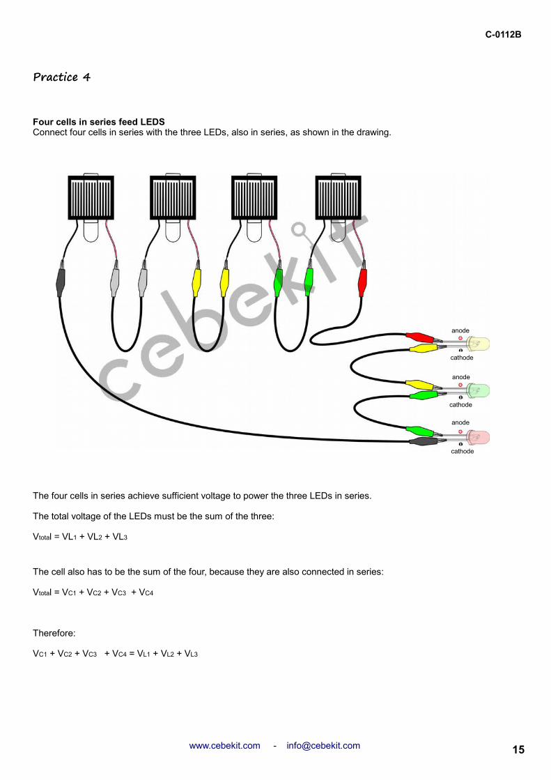
Practice 4
Four cells in series feed LEDSConnect four cells in series with the three LEDs, also in series, as shown in the drawing.
The four cells in series achieve sufficient voltage to power the three LEDs in series.
The total voltage of the LEDs must be the sum of the three:
Vtotal = VL1 + VL2 + VL3
The cell also has to be the sum of the four, because they are also connected in series:
Vtotal = VC1 + VC2 + VC3 + VC4
Therefore:
VC1 + VC2 + VC3 + VC4 = VL1 + VL2 + VL3
15www.cebekit.com - [email protected]
cathode
cathode
cathode
anode
anode
anode

16 www.cebekit.com - [email protected]
C-0112B
Practice 5
Motor powered by a cellConnect a cell with the engine that will inserted 4 blade propeller, according to the drawing.
Perform the same test with the following propellers:
See the differences between them and think why.
The differences in rates of each of the assemblies is determined by the weather, for this reason must be performed benchmark tests the same day with the same conditions. No less important are the weight of the blades and design which causes friction with air.When the motor has no load (it is said that idles), as in the case of carrying the small pulley, is when turns faster.

C-0112B
Perform the same test with the following propellers:
See the differences between them and think why.
The differences in rates of each of the assemblies is determined by the weather, for this reason must be performed benchmark tests the same day with the same conditions. No less important are the weight of the blades and design which causes friction with air.When the motor has no load (it is said that idles), as in the case of carrying the small pulley, is when turns faster.
Practice 6
Two fuel cells in series engineTwo cells connected in series with the motor that will inserted 4 blade propeller, according to the drawing.
En la conexión en serie tenemos:
Vtotal = VC1 + VC2
Itotal = IC1 = IC2
The current intensity is the same for the whole circuit, while the voltage is equal to the sum of the voltages of each cell.
17www.cebekit.com - [email protected]

C-0112B
Perform the same test with the following propellers:
See the differences between them and think why.
The differences in rates of each of the assemblies is determined by the weather, for this reason must be performed benchmark tests the same day with the same conditions. No less important are the weight of the blades and design which causes friction with air.When the motor has no load (it is said that idles), as in the case of carrying the small pulley, is when turns faster.
Practice 7
Three cells in series engine poweredConnecting three cells in series with the motor lead inserted 4 blade propeller, according to the drawing.
18
In the series connection are:
Vtotal = VC1 + VC2 + VC3
Itotal = IC1 = IC2 = IC3
The current intensity is the same for the whole circuit, while the voltage is equal to the sum of the voltages of each cell.
www.cebekit.com - [email protected]

C-0112B
Perform the same test with the following propellers:
See the differences between them and think why.
The differences in rates of each of the assemblies is determined by the weather, for this reason must be performed benchmark tests the same day with the same conditions. No less important are the weight of the blades and design which causes friction with air.When the motor has no load (it is said that idles), as in the case of carrying the small pulley, is when turns faster.
Practice 8
Four cells in series powered engineConnect four cells in series with the motor lead inserted 4 blade propeller, according to the drawing.
In the series connection are:
Vtotal = VC1 + VC2 + VC3 + VC4
Itotal = IC1 = IC2 = IC3 = IC4
The current intensity is the same for the whole circuit, while the voltage is equal to the sum of the voltages of each cell.
19www.cebekit.com - [email protected]

C-0112B
Perform the same test with the following propellers:
See the differences between them and think why.
The differences in rates of each of the assemblies is determined by the weather, for this reason must be performed benchmark tests the same day with the same conditions. No less important are the weight of the blades and design which causes friction with air.When the motor has no load (it is said that idles), as in the case of carrying the small pulley, is when turns faster.
Practice 9
Four engine fuel cells in parallelConnect four cells in parallel with the engine that will inserted 4 blade propeller, according to the drawing.Compare the results with the practice in May and think why.
In the parallel connection are:
Vtotal = VC1 = VC2 = VC3 = VC4
Itotal = IC1 + IC2 + IC3 + IC4
The resulting voltage is the same as in Practice 5 (between 1.5V and 1.8V, depending on the intensity of the sun). The resulting current can be the sum of all cells, but the engine will not absorb more than 75mA, which is the current that can give a single cell, and in practice 5.
20 www.cebekit.com - [email protected]

C-0112B
Práctica 10
Four cells in parallel powered intermittent light bulbConnect four cells in parallel with the socket, as shown in the drawing.Then place the tight bulb into the socket.
What happen ?
The bulb will light in proportion to the light it receives from the sun.Within a few seconds the current exceeds about 120mA, the bulb starts to flash, thanks to a bi-metal device that has inside along the filament.
In the parallel connection are:
Vtotal = VC1 = VC2 = VC3 = VC4
Itotal = IC1 + IC2 + IC3 + IC4
The resulting voltage is the same as in any of the cells.The intensity of the resulting current is the sum of the intensities of all cells.
21www.cebekit.com - [email protected]

C-0112B
Más prácticas
From now experience, look for other solar motors CEBEKIT as C-6060, C-6059, C-6058, etc.Also try changing the polarity (positive-negative exchange) feeding the engine and check what happens. (Attention should never feed inverted voltage to the LEDs, since you can destroy them.)Experiment half feeding motor voltage and search for devices that can feed some or all cells.
Now is the time to create self-propelled vehicles with solar energy. In our catalog www.cebekit.com find all sorts of kits and spares cell and all kinds of accessories.
Only should avoid feeding a device with a higher voltage than marked by the manufacturer.If the current generated by the solar panel is greater than that required by the powered equipment, it will not consume more than required for operation without suffering damage or affect the panel.
All knowledge is contrasted with experimentation And understanding is enriched always fun
more information
This manual along with his kit of experimentation and "My Notebook Solar" represent one of the didactic purposes CEBEKIT offers teaching in relation to renewable energy.
Wind energy, the cell or fuel cell, hydrogen, thermodynamic energy, photovoltaics,solar thermal collectors, along with others such as electronics, electricity or mechanics are some of the lines with a variety of kits and products ranging from initiation and school learning, ESO, baccalaureate, professional modules, to the use and professional installation .
22 www.cebekit.com - [email protected]

C-0112B
My Solar Notebook
Understand and learnphotovoltaic technology
23www.cebekit.com - [email protected]
C-0112B
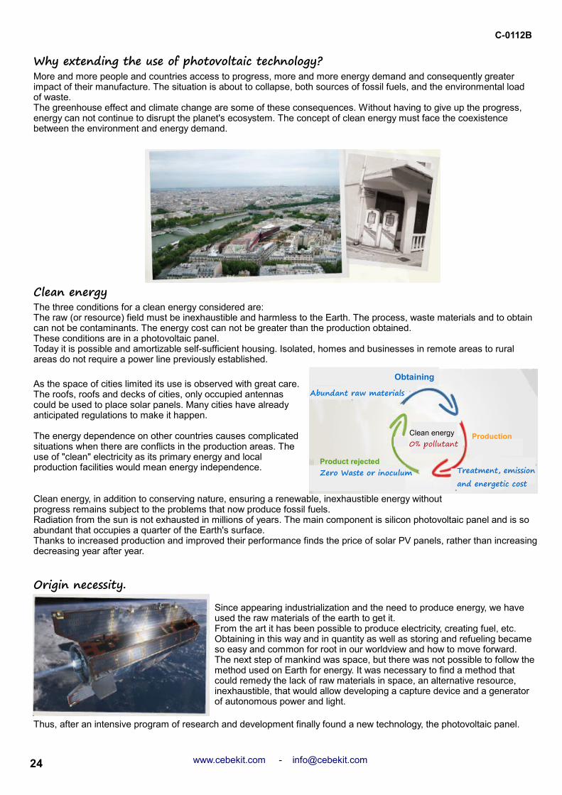
Why extending the use of photovoltaic technology?More and more people and countries access to progress, more and more energy demand and consequently greater impact of their manufacture. The situation is about to collapse, both sources of fossil fuels, and the environmental load of waste.The greenhouse effect and climate change are some of these consequences. Without having to give up the progress, energy can not continue to disrupt the planet's ecosystem. The concept of clean energy must face the coexistence between the environment and energy demand.
The three conditions for a clean energy considered are:The raw (or resource) field must be inexhaustible and harmless to the Earth. The process, waste materials and to obtain can not be contaminants. The energy cost can not be greater than the production obtained.These conditions are in a photovoltaic panel.Today it is possible and amortizable self-sufficient housing. Isolated, homes and businesses in remote areas to rural areas do not require a power line previously established.
As the space of cities limited its use is observed with great care. The roofs, roofs and decks of cities, only occupied antennas could be used to place solar panels. Many cities have already anticipated regulations to make it happen.
The energy dependence on other countries causes complicated situations when there are conflicts in the production areas. The use of "clean" electricity as its primary energy and local production facilities would mean energy independence.
Clean energy, in addition to conserving nature, ensuring a renewable, inexhaustible energy withoutprogress remains subject to the problems that now produce fossil fuels.Radiation from the sun is not exhausted in millions of years. The main component is silicon photovoltaic panel and is so abundant that occupies a quarter of the Earth's surface.Thanks to increased production and improved their performance finds the price of solar PV panels, rather than increasing decreasing year after year.
Clean energy
Origin necessity.Since appearing industrialization and the need to produce energy, we have used the raw materials of the earth to get it.From the art it has been possible to produce electricity, creating fuel, etc. Obtaining in this way and in quantity as well as storing and refueling became so easy and common for root in our worldview and how to move forward.The next step of mankind was space, but there was not possible to follow the method used on Earth for energy. It was necessary to find a method that could remedy the lack of raw materials in space, an alternative resource, inexhaustible, that would allow developing a capture device and a generator of autonomous power and light.
Thus, after an intensive program of research and development finally found a new technology, the photovoltaic panel.
24 www.cebekit.com - [email protected]
Clean energy
0% pollutant
Obtaining
Abundant raw materials
Product rejected
Zero Waste or inoculum
Production
Treatment, emission and energetic cost

C-0112B
Applying resultsSolar radiation is a constant source, at least in our solar system is an inexhaustible source of energy that can be captured in space and on Earth.
The name derives from the Greek photovoltaic technology "φῶς" (phos), meaning light, and Volta, in honor of the Italian physicist Alessandro Volta.The definition clearly sets out its function, converting light into electricity.
Photovoltaic panels are initially used in recharging the batteries in the first satellites. Over time, the panels were perfected and performance allowed without batteries, with the consequent reduction of weight and size.
Today, in addition to space vehicles and satellites, photovoltaic technology has extended its use to all types of industrial and domestic applications. From complete plants for electricity production, the more powerful exceeded 320 million watts in 2013, to countless applications such as calculators, toys, audio players, clocks, signs, life support in remote locations, autonomous lighting and progressive implementation in housing, increasing energy self-sufficient.
How is light?
The solar radiation that reaches the earth can be exploited by heat producing (solar-thermal) or by the use of light radiation (solar-photovoltaic).Light is a part of the electromagnetic radiation emitted by the sun, called solar radiation.
What is and what energy transported?Light is not an indivisible element but consists of different particles called photons, which are classified by their "color", ie its wavelength. Actually, pure white light is the sum of all colors and sunlight contains them all, even those who can not see, such as infrared and ultraviolet.
25www.cebekit.com - [email protected]
Composition of light
Prism
white light

C-0112B
How to take advantage?Not all photons have the same energy power. For example, a violet photon carries almost twice the power of a red one. This information is absolutely crucial if we want to use light as an energy source.
Light and electricityThe principle to convert light into electricity is using light as a driving force. This force should provoke a reaction that generates electricity, just as wind or water turbines push. The magnetic field within the magnetic flux causes produces electricity.But when it comes to light the process is slightly different and to understand it must be studied as acts at the atomic level.
siliconEarlier we pointed out that not all photons of light were equally potent. Thus, a material that responds the same way to the more types of photons best to harness the power of different types will be necessary. The silicon photovoltaic cell has this quality.
Silicon is the main component of ordinary sand. It is such an abundant natural resource that occupies a quarter of the Earth's crust. The main drawback and which derives most of the production cost, is the purification process (removal of impurities) to obtain the substantially pure silicon crystal.The silicon crystal is a highly ordered atomic structure. If extended overdone, would like to see a dense network of cells or ordered lots of grains, which from a distance looks like a single block.
26 www.cebekit.com - [email protected]
Power on
Wavelength(nanometers)
(nanometers)Wavelength
relative responseSilicon cell

C-0112B
When combined the silicon atoms to form a solid, make forming an ordered crystal structure called. The "covalent bonding" are the junctions between these atoms so that adjacent share electrons, thus a balance of forces that holds the atoms is created.
The strength of the covalent bond is very large because there are 8 electrons remaining in each atom, but are shared. This feature makes the covalent bonds are of great strength.
Silicon N and P.For a power flow, two types of silicon are created to promote circulation of electrons.
Some one phosphorus atom, which has five electrons in its last layer is added. By binding to silicon atoms, the predominant binding is four electrons, leaving a free electron "free association". This structure facilitates the initial conductivity of silicon and is defined as n-type silicon
The other type is silicon P. This time boron atoms having a single final layer of three electrons are added, which causes a shortage of an electron, or in other words, the opportunity for the electron "unassociated "is tapped.
Each atom shares its four valence electrons (the outer layer) with neighboring atoms, so that has 8 electrons in the valence orbit, as shown in the figure below right ..
27www.cebekit.com - [email protected]
Crystalline silicon
outer layer(4 electrons)
core
Silicon atom(Si) 14N 14P
N-type silicon
N-type silicon
Movement of electrons(electric current)

C-0112B
In principle joining a silicon layer with another silicon N P, a free electrons would be used by the other. But not so.What stimulus needed electrons in both layers of silicon?What can cause the flow of electrons from one layer to another and this atomic motion to obtain an electric current?The answer lies in transporting energy photons.
The photovoltaic solar cell.To channel and remove the electrical current between the layers of silicon and silicon P N is necessary to place a metal surface above and one below the junction. At least one of them, exposed to the sun, must be a grid to permit the passage of light through the glass. This drawback causes a drop in performance, as it hampers the passage of light and of electrons to the metal surface, since must overcome the resistance of silicon, which is a semiconductor.
Moreover, as shiny surface of a silicon crystal does not favor the penetration of photons inward, but most are reflected abroad. To avoid an anti-reflective material is used.Finally the cell is complete with a protective cover as solar glass, without impeding the passage of light, allows exposure to rain, hail, snow and impact of objects transported by wind and also anti-reflective.Generally the approximate final yield of a solar cell silicon is 15% of electricity production compared to the light received. Believe it or not its lightness and size, a solar cell does not suffer just wear, or require more maintenance than cleaning dust or dirt can be deposited on its surface.
Photovoltaic solar panel.A single cell supplies a voltage value and relatively low currents, usually around 0.5 V DC, do not approach the standard power range of devices. For higher voltages several cells together forming a panel are connected. The solar panel is made up of various groups connected in series and parallel to achieve the required voltage and current cells. Currents are usually trade tensions of 6, 9, 12 and 24 V. The output currents typically depend on the size of the cells utilized in its construction.For many installations a single panel may not be enough to feed an entire facility and becomes habitual connection between different panels for a given final value.
Positioning the panel and use the SunAlthough the Sun always appears in the east and sets in the west, depending on time of year its route occurs at varying height horizon. For the same reason, the hours of light during the day vary by season.The solar panel should be positioned so that collect the maximum amount of sunlight. To achieve this, we must find the best horizontal and vertical position, depending on the area of the globe where it is installed. The horizontal is to harness the sun's path, while the vertical is for all alike panel receives maximum radiation relative to the inclination of the sun.
For optimal situation will depend on the hemisphere where we will mount the panel, if it moved into the northern hemisphere, the panels must be facing south. Whereas if it is installed in the southern hemisphere, the panels must be faced north. Thus, during the daily path of the sun we can make the most of their radiation.
28 www.cebekit.com - [email protected]
Solar cell Base metalN-type siliconN-type silicon
conductive grid
Conductive grid
Protective Cover (Transparent)
POSITIONING OF THE PANEL
inclination
orientation

C-0112B
Ideally, you should correct the vertical inclination of the panel at least at each station. There are devices called trackers, always place the panel in the most advantageous position, but the most common practice is fixed brackets, or placed directly on the roof of a house, provided it is well oriented.
Regarding vertical inclination Gibraltar eg optimal fixed inclination is at 30 °, while in Barcelona is 35, Oslo 39 and is in Murmansk is 46º.For the customized vertical tilt for each area in Europe can be found anywhere in the European Union. This website will also provide other specific data for advanced solar applications.
http://re.jrc.ec.europa.eu/pvgis/apps4/pvest.php?lang=es&map=europe
If you want data internationally or to the US, there is another web query.
http://rredc.nrel.gov/solar/calculators/PVWATTS/version1/
In addition to the proper position, the place chosen for the panel should never be in shadow. The panel must be firmly secured, it is imperative that the wind or other mishap does not change its position. You should also prevented leaves or other elements are located on its surface, its shadow hide a part of the panel.
How much energy produces a photovoltaic system ?.The maximum power generated by a solar panel at a given location depends on the values of solar radiation during the year. As these values change according to season and depending on whether it is a cloudy day, rain or full sun, for a useful reference work, an approximate value is used, the regional factor or average daily solar radiation. This factor is the average daily radiation and is established by areas.In the Iberian peninsula is about 4, although in the north and west zone (zone I) is less than 3.8 and higher radiation areas (zone V) can exceed 5.0.The calculation of the daily production of a panel is equal to its maximum power multiplied by the regional factor.For example, a panel of 12 V and 36 W located in the Iberian peninsula, the average power generated in a single day would 36W · 4 = 144 W.
Work Units.Both cells as separate panels may be grouped in the same way, in parallel to increase the total current can be supplied, or in series with a current does not vary and the final voltage is increasing.
Before group panels, but not too deep, it is necessary to know the three basic for working with electricity and solar units.
Tension. Its unit is the volt, and is represented by "V".
1 kV = 1000 V 1 V = 1000 mV(1 kilo-volt = 1000 volt) (1 volt = 1000 mili-volt)
Why tip?
29www.cebekit.com - [email protected]
Solar panels

C-0112B
Current or intensity. Its unit is the ampere and is represented with an "A".
Power. Is the result of multiplying the voltage by the current. Its unit is the watt and is represented with a "W".
1 kW = 1000 W 1 W = 1000 mW(1 kilo-watt = 1000 watt) (1 watt = 1000 mili-watt)
The function of the power (product of voltage and current) can be cleared depending on which is the variable that we seek.
W = V · I V = I =
Example:The manufacturer states that its solar panel provides 12 V 36 WWhat is the maximum current that would provide?
We solve the formula for calculating the power versus current I =
Transferring values to the formula: I = = 3 A
It is a solar panel that can generate 3 A at 12 V.
Grouping in series and parallel ..Any equipment or electrical device operates at a specific voltage and requires (consume) a given current. Depending on these parameters, it is necessary to group several panels to get the voltage and current need.Usually the most family tensions are 230 VAC (alternating current), however in solar applications common working voltage is 12 VDC (direct current).At present there are already appliances and lamps operating above 12 VDC, but it is not possible converters teams from 12 V DC current to 230 V alternating current is used.Losses in the conversion are above 40%, while in the regulation equipment are only 30%.
Like a serial or parallel grouping is done?A panel provides a polarized voltage (DC or DC). In other words, has a positive and a negative.
A parallel combination is one in which multiple panels joined together, uniting in a single pole all positive and negative every other pole.
1 kA = 1000 A 1 A = 1000 mA(1 kilo-ampere = 1000 ampere) (1 ampere = 1000 mili-ampere)
W I
W V
W V
36 12
30 www.cebekit.com - [email protected]
Association parallel panels
Solar panels (back)

When several panels were connected in series ?.
C-0112B
When you want to raise the voltage.The resulting voltage is equal to the sum of the voltages of each panel. The current change does not vary.
Example:Calculate the mass exit to join three equal photovoltaic panels, 12 V and 3 A each.
The final voltage is equal to the sum of the three voltages. 12 V + 12 V + 12V = 36 VThe resulting current or intensity not change, will remain at 3 APower is the result of the voltage and current, ie 36 V x 3 A = 108 W
When panels were connected in parallel ?.When you want to get a higher current.In this case the tension is maintained and the current will be the sum of all.
Example:Calculate the exit to join three equal parallel photovoltaic panels, 12 V and 3 A each.
The final voltage is 12 VThe current will be equal to the sum of the three. 3 A + 3 A + 3 A = 9 A.The power also here changes, but the end result the same value, 12 V x 9 A = 108 W
A mixed system is possible?A group of PV (photovoltaic) panels joined together in series can be grouped with another group perfectly PV panels joined together in parallel, as it suits .. Example:Imagine that a final voltage of 24 V and a current of 21 A is necessary, but only available panels 12 V and 3 A to get it. Can we do the assembly with these panels?
The solution is simple. First, it seeks to obtaining the final voltage. We will first grouping of two panels in series. The result will be 12 V + 12 V = 24 V and 3 A.To achieve the 21 A, the current value between 3 A, which is the current of each panel is divided.
Therefore, = 7 groupos So 7 groups should be created in parallel 24 V and 3 A (each group will consist of two panels in series).In short, we need 14 panels 12 V and 3 A and get 24 V and 21 A, which will give us a power of 24V x 21 A = 504 W
An association in series is that in which binds the positive pole to the negative pole of the next module. As if railcars it were. At the end there is always a free positive and negative free at each end of the association.
21A 3 A
31www.cebekit.com - [email protected]
Solar panels (back)
Association of panels in series

.
C-0112B
Teaching materials for learning practices in educational settings under the supervision of an adult instructor. This product IS NOT A TOY. Not suitable for children under 3 years due to small parts that can be swallowed. Keep this brochure and contact details
32
NOTE: This kit is for children from 12 years if accompanied by an adult
www.cebekit.com - [email protected]