solar gas turbine systems with centrifugal particle receivers, for ...€¦ · solar gas turbine...
TRANSCRIPT
Energy Procedia 69 ( 2015 ) 1382 – 1392
Available online at www.sciencedirect.com
ScienceDirect
1876-6102 © 2015 Published by Elsevier Ltd. This is an open access article under the CC BY-NC-ND license (http://creativecommons.org/licenses/by-nc-nd/4.0/).Peer review by the scientific conference committee of SolarPACES 2014 under responsibility of PSE AGdoi: 10.1016/j.egypro.2015.03.131
International Conference on Concentrating Solar Power and Chemical Energy Systems, SolarPACES 2014
Solar gas turbine systems with centrifugal particle receivers, for remote power generation
T.Prosina*, T.Pryora, C.Creagha, L.Amsbeckb, R.Uhligb aMurdoch University, 90 South Street, 6150 Perth, WA, Australia
bInstitute of Solar Research, German Aerospace Centre (DLR), Pfaffenwaldring 38-40, 70569 Stuttgart, BW, Germany
Abstract
There is a growing demand from remote communities in Australia to increase the amount of decentralised renewable energy in their energy supply mix in order to decrease their fuel costs. In contrast to large scale concentrated solar power (CSP) plants, small solar-hybrid gas turbine systems promise a way to decentralise electricity generation at power levels in the range of 0.1-10MWe, and reduce to cost of energy production for off-grid, isolated communities. Thermal storage provides such CSP systems with an advantage over photovoltaic (PV) technology as this would be potentially cheaper than adding batteries to PV systems or providing stand-by back-up systems such as diesel fuelled generators. Hybrid operation with conventional fuels and solar thermal collection and storage ensures the availability of power even if short term solar radiation is not sufficient or the thermal storage is empty. This paper presents initial modelling results of a centrifugal receiver (CentRec) system, using hourly weather data of regional Australia for a 100kWe microturbine as well as a more efficient and cost effective 4.6MWe unit. The simulations involve calculation and optimisation of the heliostat field, by calculating heliostat by heliostat annual performance. This is combined with a model of the receiver efficiency based on experimental figures and a model of the particle storage system and turbine performance data. The optimized design for 15 hours of thermal storage capacity results in a tower height of 35m and a solar field size of 2100m2 for the 100kWe turbine, and a tower height of 115m and solar field size of 50 000m2 for the 4.6MWe turbine. The solar field provides a greater portion of the operational energy requirement for the 100kWe turbine, as the TIT of the 4.6MWe turbine (1150°C) is greater than what the solar system can provide. System evaluations of the two particle receiver systems, with a selection of cost assumptions, are then compared to the current conventional means of supplying energy in such remote locations. © 2015 The Authors. Published by Elsevier Ltd. Peer review by the scientific conference committee of SolarPACES 2014 under responsibility of PSE AG.
* Corresponding author. Tel.: +61 (0)8 6260 0952.
E-mail address: [email protected]
© 2015 Published by Elsevier Ltd. This is an open access article under the CC BY-NC-ND license (http://creativecommons.org/licenses/by-nc-nd/4.0/).Peer review by the scientific conference committee of SolarPACES 2014 under responsibility of PSE AG
T. Prosin et al. / Energy Procedia 69 ( 2015 ) 1382 – 1392 1383
Keywords: CSP; microturbine; particle receiver; centrifugal; heliostat field; solar hybrid
1. Introduction
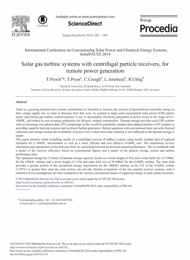
The production of energy in off-grid locations has become increasingly expensive with increased diesel fuel cost. In areas with no grid connection, where the scale of the demand is too low to justify a gas pipeline connection energy production is served by diesel generators. Since there is no grid connection and in order to ensure dependable power generation, the energy production needs to be base load or dispatchable (to cover all the energy demand without any breaks in production). For this reason, renewable generators, operating only from an intermittent power source such as wind turbines or solar photovoltaics are unsuitable. Since some solar thermal CSP plants can incorporate thermal energy storage and operate in hybrid with other fuels, supply security can be guaranteed. As in many nations in the world, in Australia these areas are often in locations with high solar resource. This paper assesses the potential of a promising application of storage capable particle receiver CSP technology for small scale hybrid solar energy production in isolated power islands, such as those in the mining rich regions of the Kimberly and Pilbara of North-Western Australia. This is accomplished by comparing particle CSP hybrid gas turbine plants with storage, which are powered by solar and diesel fuel, to conventional diesel generator systems. Solar data from Broome (17.95°S, 122.22°E) circled in Fig. 1, has been used to represent a typical location for the market of this application.
Fig. 1. Annual solar resource for Australia and selected data sites from the Australian Bureau of Meteorology.
2. Description of the technology
A Brayton cycle turbine system is appropriate for small scale power generation in hot remote locations. This is because compared to steam turbines, they have relatively high efficiency at low power levels. Furthermore, gas turbines do not require large amounts of water for the cycle, which could be problematic for dry remote areas where water is scarce. Gas turbine can be powered by heating air to a high temperature by gas combustion, diesel fuel
1384 T. Prosin et al. / Energy Procedia 69 ( 2015 ) 1382 – 1392
combustion or by concentrated solar thermal energy. These engines are most efficient when operating at high temperatures, therefore a high temperature capable system is required.
Solar-hybrid microturbine systems have been developed and tested [1], with metallic tube solar receiver technology placed on a tower surrounded by heliostats. The receiver heated the working fluid of a 100kWe nominal power microturbine with design turbine inlet temperature (TIT) of 950°C. A similar system with a metallic tube receiver and pressurised fixed bed thermal storage with a blower has been designed and analysed by the DLR [2]. Limitations of this CSP technology concept and others either limit the maximum receiver operating temperature to 800°C, or do not easily enable the use of economic energy storage, which can result in decreased turbine efficiency and/or very low annual solar share. An appropriate option is to utilize particle receiver technology, which because of its storage and very high temperature capability, enables high design point solar share (solar only operation of the microturbine) and high annual solar share for maximum fuel saving.
2.1. The cycle
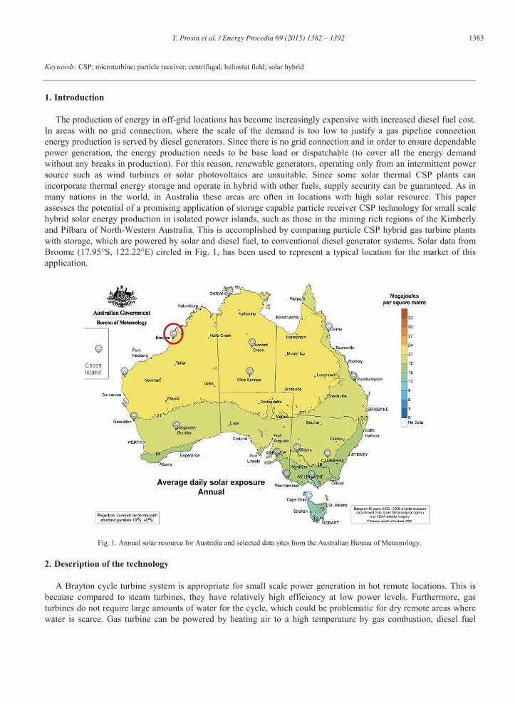
The solar hybrid gas turbine system functions by first concentrating solar energy from a heliostat field (solar field) to a receiver mounted on top of a tower. The incoming particles delivered by a lift system to the receiver are heated by direct exposure to concentrated radiation. The hot particles leaving the receiver are transferred directly into insulated non-pressurised storage, above a heat exchanger. Energy is transferred from the particles to the Brayton cycle via a particle-to-pressurized-air, high temperature heat exchanger (HTEX). After heat exchange, the cool particles are then transferred to low temperature storage, where they can be delivered to the receiver for solar heating by the lift system. Fig. 2 depicts the operation of the solar system together with a recuperated gas turbine. A promising particle receiver concept suitable for this system is the centrifugal particle receiver (CentRec) [3].
Fig.2. Schematic of a hybrid solar particle receiver recuperated gas turbine system with thermal energy storage.
2.2. Centrifugal solid particle receiver
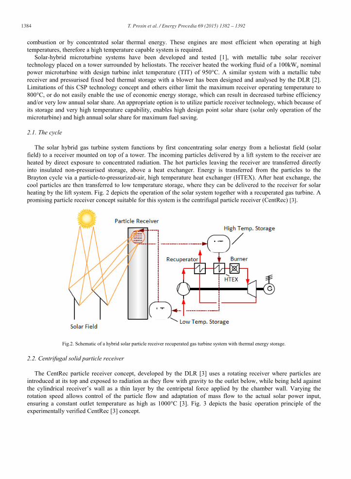
The CentRec particle receiver concept, developed by the DLR [3] uses a rotating receiver where particles are introduced at its top and exposed to radiation as they flow with gravity to the outlet below, while being held against the cylindrical receiver’s wall as a thin layer by the centripetal force applied by the chamber wall. Varying the rotation speed allows control of the particle flow and adaptation of mass flow to the actual solar power input, ensuring a constant outlet temperature as high as 1000°C [3]. Fig. 3 depicts the basic operation principle of the experimentally verified CentRec [3] concept.
T. Prosin et al. / Energy Procedia 69 ( 2015 ) 1382 – 1392 1385
Fig. 3. Centrifugal particle receiver operation [3].
2.3. Heat exchanger
The heat exchange from the hot particles under ambient pressure to the pressurized air of the gas turbine is a significant challenge. A first heat exchanger operating by indirect heat transfer needed to be designed. Due to the high particle temperatures, metallic materials are critical as they need a corrosion protection to protect themselves from catastrophic oxidation. Once the very hard particles move along metallic surfaces they could scratch away the oxide layer. This oxidation layer has to be built again and again and after many cycles the oxide building components of the alloy are exhausted.
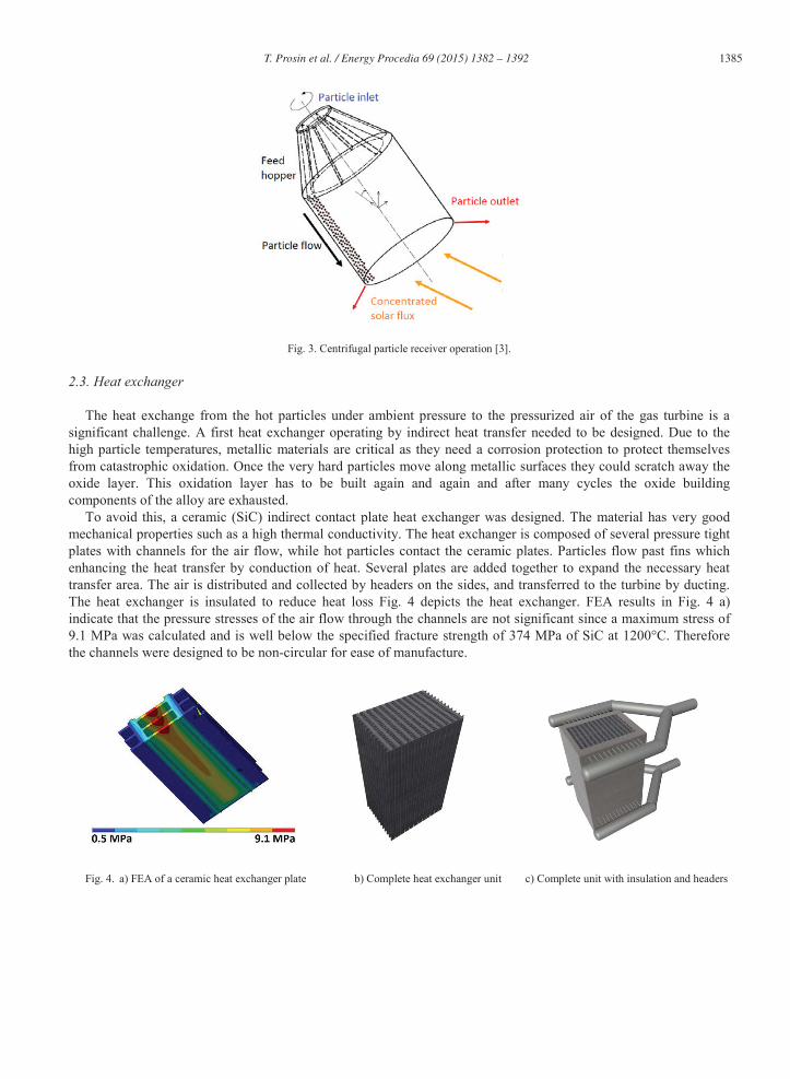
To avoid this, a ceramic (SiC) indirect contact plate heat exchanger was designed. The material has very good mechanical properties such as a high thermal conductivity. The heat exchanger is composed of several pressure tight plates with channels for the air flow, while hot particles contact the ceramic plates. Particles flow past fins which enhancing the heat transfer by conduction of heat. Several plates are added together to expand the necessary heat transfer area. The air is distributed and collected by headers on the sides, and transferred to the turbine by ducting. The heat exchanger is insulated to reduce heat loss Fig. 4 depicts the heat exchanger. FEA results in Fig. 4 a) indicate that the pressure stresses of the air flow through the channels are not significant since a maximum stress of 9.1 MPa was calculated and is well below the specified fracture strength of 374 MPa of SiC at 1200°C. Therefore the channels were designed to be non-circular for ease of manufacture.
Fig. 4. a) FEA of a ceramic heat exchanger plate b) Complete heat exchanger unit c) Complete unit with insulation and headers
1386 T. Prosin et al. / Energy Procedia 69 ( 2015 ) 1382 – 1392
Table 1 presents the design parameters for a heat exchanger to work in combination with a 100kWe microturbine. Designing the heat exchanger according to the parameters depicted in Table 1 the required heat transfer area was found to be 7.2m2.
Table 1. Heat exchanger design parameters
Unit Value
Inlet temperature - air °C 600
Outlet temperature - air °C 950
Mass flow – air kg/s 0.8
Pressure drop air mbar 100
Inlet temperature – particles °C 1000
Outlet temperature – particles °C 700
Mass flow – particles kg/s 0.89
Drawing from the knowledge of a potential manufacturer with experience in constructing similar components, an
estimated price of $AU 385 thousand for the unit was calculated, (including the costs for first time engineering). From experience with technology development, we expect cost reduction for future units as well as serial production to enable great cost reduction. Given thermal capacity this unit was designed for, the specific cost of the prototype of this technology is 1200 $AU/kWth.
3. Methodology
The market opportunity for off-grid energy production using solar hybrid gas turbine systems based on CentRec technology was assessed by comparing energy generation costs for these systems to that of conventional diesel generation of power. Cost optimized designs of the power plant operating for base load electricity production were calculated using a selection of possible costs for components as inputs to a selection of annual simulation tools. Off-design efficiency of the turbines due to fluctuating ambient temperature was included in the simulation. HFLCal [4] was used to optimize the size and positioning of the heliostats in the solar field. This software also generated an efficiency map for solar positions, which was fed into a main annual performance model for calculating annual yield. The annual model included calculation of storage charging and discharging, storage capacity optimization, as well as a detailed validated thermodynamic receiver model. Supplier information and other thermodynamic considerations were used to model thermal and other performance losses from the system at every macro-component of the system. Electrical parasitic demands such as to power the heliostat field and the lift system were also incorporated. For calculation of payback time, a cost model for operations and maintenance (O&M) was created for the CSP plants assuming that as much as possible of daily operation was conducted remotely to minimise the O&M costs of the CSP plants as described in another study [9]. It was assumed the calculated O&M costs would increase approximately in line with inflation (3% per year). The baseline cost of diesel fuel electricity generation was calculated according to Eq. 1 and Eq. 2 below, where Ka is the annual lifetime cost of energy production, Qel is the total annual electricity replaced by a hybrid system, G is the efficiency of the diesel generator (assumed to be 40%), C is the cost per MWhth of diesel fuel, PL is the average price of diesel fuel per litre over the operational life of the power plant and HHVD is the higher heating value of the diesel fuel in MWhth per litre.
Eq. 1 Ka= (C ÷ G).Qel Eq. 2 C = PL ÷ HHVD
4. System 1 – 100kWe
A small scale hybrid system can be designed based on a 100kWe Turbec T100 microturbine with, according to the manufacturer 31% efficiency at ISO conditions, at a turbine inlet temperature (TIT) of 950°C and a post
T. Prosin et al. / Energy Procedia 69 ( 2015 ) 1382 – 1392 1387
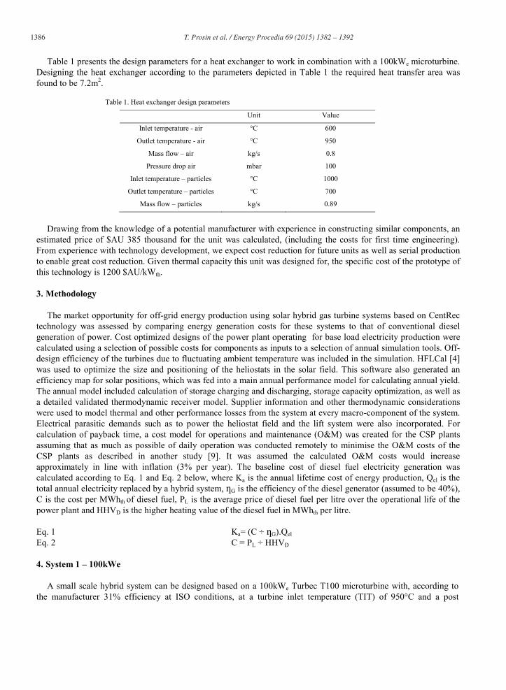
recuperator temperature of 600°C. As the highest temperature the CentRec can currently achieve is 1000°C, and a particle-air heat exchanger might provide a driving temperature difference of 50K at the high temperature exchange (and 100K for low temperature exchange), the maximum solar air temperature would be 950°C. This would enable 100% solar only operation at design point for the CentRec concept with this turbine. The receiver inlet temperature (cold particles) is 700°C as the cycle working fluid temperature after the recuperator is 600°C. Fig. 5 shows the optimised heliostat layout of the 1.1MWth receiver, tilted at 65°, powering the microturbine, resulting in a solar multiple of 3.4 and storage capacity of 15 hours. Due to the low receiver size and astigmatism small 8m2 heliostats with two facets were chosen as the scale is typical for smaller CSP towers.
Fig. 5. Solar field layout with annual heliostat efficiency – 8m2 heliostat size and 1.1 MWth receiver capacity (optimised aperture to 0.5m2)
5. System 2 – 4.6MWe
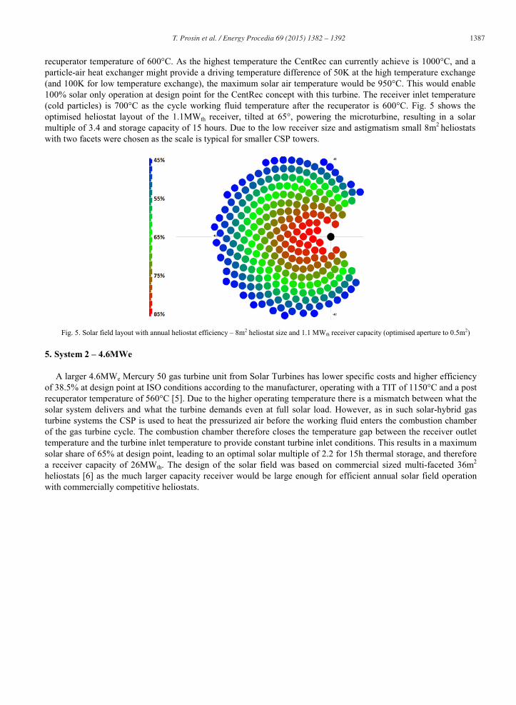
A larger 4.6MWe Mercury 50 gas turbine unit from Solar Turbines has lower specific costs and higher efficiency of 38.5% at design point at ISO conditions according to the manufacturer, operating with a TIT of 1150°C and a post recuperator temperature of 560°C [5]. Due to the higher operating temperature there is a mismatch between what the solar system delivers and what the turbine demands even at full solar load. However, as in such solar-hybrid gas turbine systems the CSP is used to heat the pressurized air before the working fluid enters the combustion chamber of the gas turbine cycle. The combustion chamber therefore closes the temperature gap between the receiver outlet temperature and the turbine inlet temperature to provide constant turbine inlet conditions. This results in a maximum solar share of 65% at design point, leading to an optimal solar multiple of 2.2 for 15h thermal storage, and therefore a receiver capacity of 26MWth. The design of the solar field was based on commercial sized multi-faceted 36m2
heliostats [6] as the much larger capacity receiver would be large enough for efficient annual solar field operation with commercially competitive heliostats.
1388 T. Prosin et al. / Energy Procedia 69 ( 2015 ) 1382 – 1392
Fig. 6. Solar field layout with annual heliostat efficiency – 36m2 heliostat size and 26MWth receiver capacity (optimised aperture to 9.5m2)
6. Conventional power generation
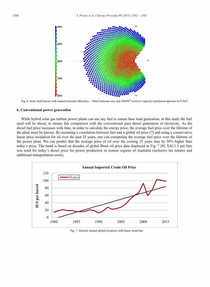
While hybrid solar gas turbine power plants can use any fuel to ensure base load generation, in this study the fuel used will be diesel, to ensure fair comparison with the conventional pure diesel generation of electricity. As the diesel fuel price increases with time, in order to calculate the energy price, the average fuel price over the lifetime of the plant must be known. By assuming a correlation between fuel and a global oil price [7] and using a conservative linear price escalation for oil over the past 25 years, one can extrapolate the average fuel price over the lifetime of the power plant. We can predict that the average price of oil over the coming 25 years may be 50% higher than today’s price. The trend is based on decades of global Brent oil price data displayed in Fig. 7 [8]. $AU1.5 per litre was used for today’s diesel price for power production in remote regions of Australia (inclusive tax rebates and additional transportation costs).
Fig. 7. Historic annual global oil prices with linear trend line
0
20
40
60
80
100
120
1988 1993 1998 2003 2008 2013
$US
per
barr
el
Annual Imported Crude Oil Price
Oil price
T. Prosin et al. / Energy Procedia 69 ( 2015 ) 1382 – 1392 1389
7. Economic performance
In order to avoid setting artificial economic boundary conditions on the systems, which are necessary for the calculation of energy cost of capital intensive power stations; and are highly dependent of the financing conditions, simple payback time is used as a figure of merit. Simple payback time, in years, is simply the total project cost divided by the average annual fuel savings of the project. This can be calculated by the annual lifetime cost of diesel energy production from (Ka from Eq. 1) minus lifetime average O&M costs and the annual cost of diesel fuel burned for hybridisation. The power plants are based on turbine specific costs, including re-engineering for solarisation, of $AU 3000/kWe for the 100kWe engine [9] and $AU 1350/kWe for the 4.6MWe engine [10]. All power plants included approximately 25% additional indirect costs for project management, project development, engineering, procurement, on-site manufacture and contingencies. A further miscellaneous costs surcharge of 15% of the cost of locally manufactured components was added to account for the additional cost of remote construction. Table 2. Shows a range of payback times for the 100kWe system, for heliostat and heat exchanger costs, given receiver costs of $AU 300k /m2 aperture, and storage costs of $AU 30/kWhth. All costs in the tables below are representative of what may be possible for a prototype plant, and therefore do not represent the potential of the mature technology, with lower cost serial manufacture of components.
Table 2. 100kWe system payback time (years) and component cost matrix for variable heliostat and heat exchanger costs
Heliostat / HTEX cost 400 $AU/kWth 800 $AU/kWth 1200 $AU/kWth
200 $AU/m² 11.5 12.5 13.5
250 $AU/m² 12.6 13.6 14.7
300 $AU/m² 13.8 14.8 15.9
Table 3. Shows a range of payback times of the 100kWe system, for variable storage and receiver costs, given a
heliostat cost of $AU250/m2 and heat exchanger costs of $AU800/kWth.
Table 3. 100kWe system payback time (years) and component cost matrix for variable storage and receiver costs
Receiver / Storage cost 25 $AU/kWhth 30 $AU/kWhth 35 $AU/kWhth
200k $AU/m² 12.9 13.1 13.4
300k $AU/m² 13.4 13.6 13.9
400k $AU/m² 13.9 14.1 14.4
The baseline payback time of the 100kWe system is approximately 13.6 years. This in the context of a 25 year
power plant is not poor, however the strength of the business case is not extraordinary. Table 4. Shows a range of payback times of the 4.6MWe system, for heliostat and heat exchanger costs, given receiver costs of $AU 300k /m2
aperture, and storage costs of $AU 30/kWth.
Table 4. 4.6MWe system payback time and component cost matrix (years) for variable heliostat and heat exchanger costs
Heliostat / HTEX cost 400 $AU/kWth 800 $AU/kWth 1200 $AU/kWth
200 $AU/m² 5.2 7.2 6.7
250 $AU/m² 5.7 6.4 7.1
300 $AU/m² 6.2 6.9 7.6
Table 5. Shows a range of payback times of the 4.6MWe system, for variable storage and receiver costs, given a
heliostat cost of $AU 250/m2 and heat exchanger costs of $AU 800/kWth.
1390 T. Prosin et al. / Energy Procedia 69 ( 2015 ) 1382 – 1392
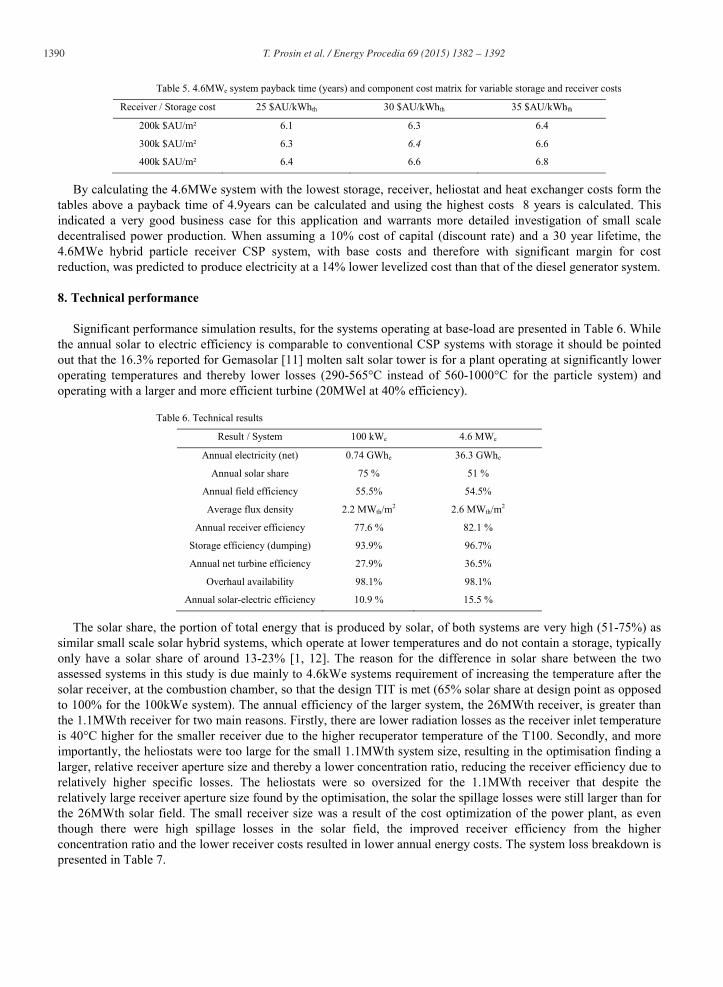
Table 5. 4.6MWe system payback time (years) and component cost matrix for variable storage and receiver costs
Receiver / Storage cost 25 $AU/kWhth 30 $AU/kWhth 35 $AU/kWhth
200k $AU/m² 6.1 6.3 6.4
300k $AU/m² 6.3 6.4 6.6
400k $AU/m² 6.4 6.6 6.8
By calculating the 4.6MWe system with the lowest storage, receiver, heliostat and heat exchanger costs form the tables above a payback time of 4.9years can be calculated and using the highest costs 8 years is calculated. This indicated a very good business case for this application and warrants more detailed investigation of small scale decentralised power production. When assuming a 10% cost of capital (discount rate) and a 30 year lifetime, the 4.6MWe hybrid particle receiver CSP system, with base costs and therefore with significant margin for cost reduction, was predicted to produce electricity at a 14% lower levelized cost than that of the diesel generator system.
8. Technical performance
Significant performance simulation results, for the systems operating at base-load are presented in Table 6. While the annual solar to electric efficiency is comparable to conventional CSP systems with storage it should be pointed out that the 16.3% reported for Gemasolar [11] molten salt solar tower is for a plant operating at significantly lower operating temperatures and thereby lower losses (290-565°C instead of 560-1000°C for the particle system) and operating with a larger and more efficient turbine (20MWel at 40% efficiency).
Table 6. Technical results
Result / System 100 kWe 4.6 MWe
Annual electricity (net) 0.74 GWhe 36.3 GWhe
Annual solar share 75 % 51 %
Annual field efficiency 55.5% 54.5%
Average flux density 2.2 MWth/m2 2.6 MWth/m2
Annual receiver efficiency 77.6 % 82.1 %
Storage efficiency (dumping) 93.9% 96.7%
Annual net turbine efficiency 27.9% 36.5%
Overhaul availability 98.1% 98.1%
Annual solar-electric efficiency 10.9 % 15.5 %
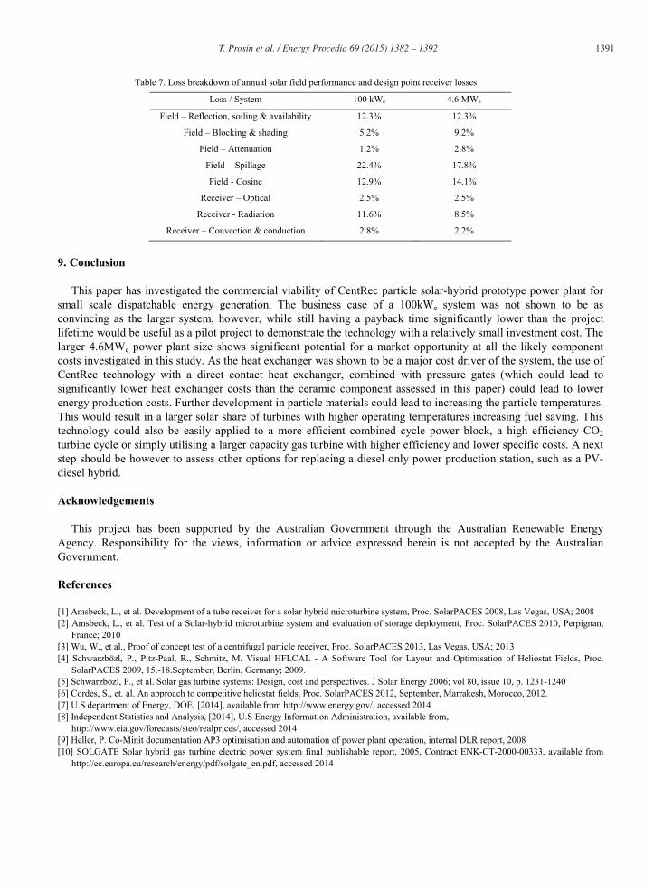
The solar share, the portion of total energy that is produced by solar, of both systems are very high (51-75%) as similar small scale solar hybrid systems, which operate at lower temperatures and do not contain a storage, typically only have a solar share of around 13-23% [1, 12]. The reason for the difference in solar share between the two assessed systems in this study is due mainly to 4.6kWe systems requirement of increasing the temperature after the solar receiver, at the combustion chamber, so that the design TIT is met (65% solar share at design point as opposed to 100% for the 100kWe system). The annual efficiency of the larger system, the 26MWth receiver, is greater than the 1.1MWth receiver for two main reasons. Firstly, there are lower radiation losses as the receiver inlet temperature is 40°C higher for the smaller receiver due to the higher recuperator temperature of the T100. Secondly, and more importantly, the heliostats were too large for the small 1.1MWth system size, resulting in the optimisation finding a larger, relative receiver aperture size and thereby a lower concentration ratio, reducing the receiver efficiency due to relatively higher specific losses. The heliostats were so oversized for the 1.1MWth receiver that despite the relatively large receiver aperture size found by the optimisation, the solar the spillage losses were still larger than for the 26MWth solar field. The small receiver size was a result of the cost optimization of the power plant, as even though there were high spillage losses in the solar field, the improved receiver efficiency from the higher concentration ratio and the lower receiver costs resulted in lower annual energy costs. The system loss breakdown is presented in Table 7.
T. Prosin et al. / Energy Procedia 69 ( 2015 ) 1382 – 1392 1391
Table 7. Loss breakdown of annual solar field performance and design point receiver losses
Loss / System 100 kWe 4.6 MWe
Field – Reflection, soiling & availability 12.3% 12.3%
Field – Blocking & shading 5.2% 9.2%
Field – Attenuation 1.2% 2.8%
Field - Spillage 22.4% 17.8%
Field - Cosine 12.9% 14.1%
Receiver – Optical 2.5% 2.5%
Receiver - Radiation 11.6% 8.5%
Receiver – Convection & conduction 2.8% 2.2%
9. Conclusion
This paper has investigated the commercial viability of CentRec particle solar-hybrid prototype power plant for small scale dispatchable energy generation. The business case of a 100kWe system was not shown to be as convincing as the larger system, however, while still having a payback time significantly lower than the project lifetime would be useful as a pilot project to demonstrate the technology with a relatively small investment cost. The larger 4.6MWe power plant size shows significant potential for a market opportunity at all the likely component costs investigated in this study. As the heat exchanger was shown to be a major cost driver of the system, the use of CentRec technology with a direct contact heat exchanger, combined with pressure gates (which could lead to significantly lower heat exchanger costs than the ceramic component assessed in this paper) could lead to lower energy production costs. Further development in particle materials could lead to increasing the particle temperatures. This would result in a larger solar share of turbines with higher operating temperatures increasing fuel saving. This technology could also be easily applied to a more efficient combined cycle power block, a high efficiency CO2 turbine cycle or simply utilising a larger capacity gas turbine with higher efficiency and lower specific costs. A next step should be however to assess other options for replacing a diesel only power production station, such as a PV-diesel hybrid.
Acknowledgements
This project has been supported by the Australian Government through the Australian Renewable Energy Agency. Responsibility for the views, information or advice expressed herein is not accepted by the Australian Government.
References
[1] Amsbeck, L., et al. Development of a tube receiver for a solar hybrid microturbine system, Proc. SolarPACES 2008, Las Vegas, USA; 2008 [2] Amsbeck, L., et al. Test of a Solar-hybrid microturbine system and evaluation of storage deployment, Proc. SolarPACES 2010, Perpignan,
France; 2010 [3] Wu, W., et al., Proof of concept test of a centrifugal particle receiver, Proc. SolarPACES 2013, Las Vegas, USA; 2013 [4] Schwarzbözl, P., Pitz-Paal, R., Schmitz, M. Visual HFLCAL - A Software Tool for Layout and Optimisation of Heliostat Fields, Proc.
SolarPACES 2009, 15.-18.September, Berlin, Germany; 2009. [5] Schwarzbözl, P., et al. Solar gas turbine systems: Design, cost and perspectives. J Solar Energy 2006; vol 80, issue 10, p. 1231-1240 [6] Cordes, S., et. al. An approach to competitive heliostat fields, Proc. SolarPACES 2012, September, Marrakesh, Morocco, 2012. [7] U.S department of Energy, DOE, [2014], available from http://www.energy.gov/, accessed 2014 [8] Independent Statistics and Analysis, [2014], U.S Energy Information Administration, available from,
http://www.eia.gov/forecasts/steo/realprices/, accessed 2014 [9] Heller, P. Co-Minit documentation AP3 optimisation and automation of power plant operation, internal DLR report, 2008 [10] SOLGATE Solar hybrid gas turbine electric power system final publishable report, 2005, Contract ENK-CT-2000-00333, available from
http://ec.europa.eu/research/energy/pdf/solgate_en.pdf, accessed 2014

1392 T. Prosin et al. / Energy Procedia 69 ( 2015 ) 1382 – 1392
[11] Sener Power and Process, Gemasolar power plant, available from, http://www.sener-power-process.com/ENERGIA/ProjectsI/gemasolar/en, accessed 2014
[12] Giuliano, S., et al. Analysis of solar-hybrid gas turbine cogeneration systems with absorption chiillers in hot and dry climates, Proc. SolarPACES 2009, 15.-18.September, Berlin, Germany; 2009