solar energy labs – part 1 engr 1181. today's learning objectives after today's class,...
TRANSCRIPT

Solar Energy Labs – Part 1ENGR 1181

Today's Learning Objectives
After today's class, students will be able to:• Describe and build both a calibration and solar
meter circuit • Convert decimal values to binary values • Discuss how a potentiometer works • Explain how a photodiode light sensor works• Compare a pictorial image of a circuit to a
schematic wiring diagram • Use a Photodiode Light Sensor and a Binary
Voltmeter circuit to measure the intensity of light (in Watts/m2)

Solar Energy Meter
In lab today, you will build a solar energy meter circuit to measure the energy intensity from a light source.
solar energy meter
Output :watts/m2

Solar Energy Meter Parts
5 Volt power supply
DMM
Breadboard
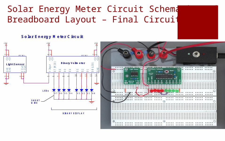
Solar Energy Meter Circuit Schematic and Breadboard Layout – Final Circuit
+5 V +5 V+5 V
P C B 1
Light Se ns or
5
2 1
63 4
V O
ut
+5
V+
5V
V O
ut
Gn
dG
nd
P C B 2
Bina ry Voltm e te r
6
2 1
75 14
4 3
8 9 10
11
12
13
D7
(M
SB
)
+5
V+
5V
D6
V I
np
ut
Gn
d
+5
V+
5V
D5
D4
D3
D2
D1
D0
(L
SB
)D 7
D 6
D 5
D 4
D 3
D 2
D 1
D 0
BINA RY DISPL A Y
SHORTW IRE
S o la r E n e r g y M e te r C ir c u it
L EDs
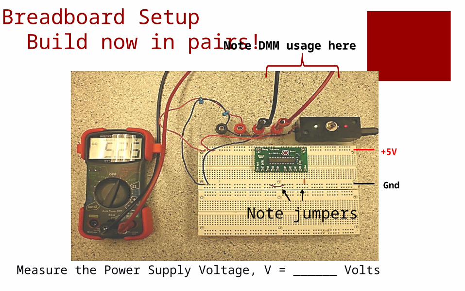
Breadboard Setup Build now in pairs!
Measure the Power Supply Voltage, V = ______ Volts
+5V
Gnd
Note DMM usage here
Note jumpers

Calibrate the Binary Voltmeter
+5 V
+5 V +5 V
1 0 K
P O T
13
2
P C B 2
Bina ry Voltm e te r
6
2 1
75 14
4 3
8 9 10
11
12
13
D7
(M
SB
)
+5
V+
5V
D6
V I
np
ut
Gn
d
+5
V+
5V
D5
D4
D3
D2
D1
D0
(L
SB
)
D 7 D 6
D 5
D 4
D 3
D 2
D 1
D 0
SHORTW IRE
B in a r y V o ltm e te r C a lib r a tio n C ir c u it
L EDs
0 to +5 V OL T S
BINA RY DISPL A Y
DMM
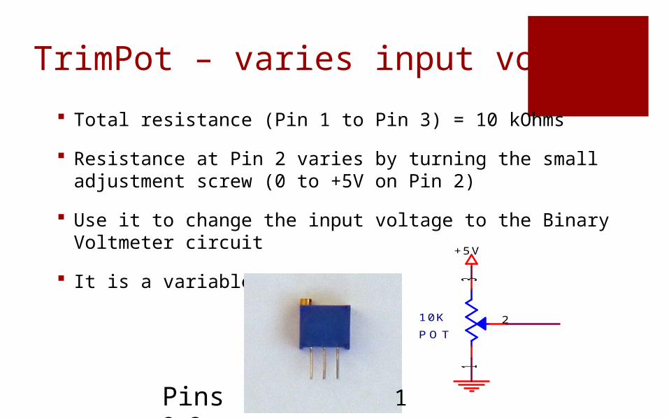
TrimPot – varies input voltage
Total resistance (Pin 1 to Pin 3) = 10 kOhms
Resistance at Pin 2 varies by turning the small adjustment screw (0 to +5V on Pin 2)
Use it to change the input voltage to the Binary Voltmeter circuit
It is a variable resistor.+5 V
1 0 K
P O T
13
2
Pins 1 2 3

8-Bit Binary Display
• The LEDs at the output of the Binary Voltmeter are labeled from D7 to D0
• The LEDs have two digital states, on and off, representing the binary numbers “1” and “0”
• D7 is the Most Significant Bit (MSB). D0 is the Least Significant Bit (LSB)
• The 8-bit binary number can be converted to a decimal number using a formula
D 7 D 6
D 5
D 4
D 3
D 2
D 1
D 0
8-BIT BINA RY DISPL A Y
L EDs
MSB LSB

8-bit Binary Numbers
00000101 = 5
LSBMSB
…. + 0*23 + 1*22 + 0*21 + 1*20
= 5
For example, convert binary 0 0 0 0 0 1 0 1 into a decimal:

The Calibration Circuit
+5V
Gnd
Short wire of LEDs must be toward ground side
• Place the TrimPot as shown and:
• Connect Pin 1 to Ground
• Connect Pin 3 to +5 Volts
• Connect Pin 2 to V Input on the Binary Voltmeter
• Connect the LEDs
• Connect the Red DMM wire to V Input
+5
V
10
K
PO
T1 3
2

• ENGR 1181 First-Year Engineering Program
Calibrate the Binary Voltmeter CircuitTable A – record and store in lab spreadsheet
Set Voltage Record Binary Numbers Calculate Decimal Values
0 0 0 0 0 0 0 0 0 0
0.5
1.0
1.5
2.0
2.5
3.0
3.5
4.0
4.5
5.0
Full CW

Solar Energy Meter Circuit Schematic and Layout
+5 V +5 V+5 V
P C B 1
Light Se ns or
5
2 1
63 4
V O
ut
+5
V+
5V
V O
ut
Gn
dG
nd
P C B 2
Bina ry Voltm e te r
6
2 1
75 14
4 3
8 9 10
11
12
13
D7
(M
SB
)
+5
V+
5V
D6
V I
np
ut
Gn
d
+5
V+
5V
D5
D4
D3
D2
D1
D0
(L
SB
)
D 7 D 6
D 5
D 4
D 3
D 2
D 1
D 0
BINA RY DISPL A Y
SHORTW IRE
S o la r E n e r g y M e te r C ir c u it
L EDs

Task 3 – How the Light Sensor Works
• The Photodiode converts light photons to a current
• The Amplifier converts the current to a voltage
• The voltage output of the Light Sensor Board is proportional to the intensity of sunlight (Isolar, Watts / m2)
The calibration equation for the Solar Light Meter is:
Isolar = 5.0 Ndecimal (Watts / m2)
Isolar
AmplifierPhotodiode
V Output

Use the Solar Energy Meter to measure the intensity of a light source
Place the spotlight in the ring stand so that the front of the bulb is 13 inches away from the top of the Light Sensor.
Make sure that the Photodiode is directly in the center of the beam.
Measure the Intensity of the light source at distances of 23, 19, 15, 11 and 7 inches.
Comment on shading LEDS and Blinking on least significant digits

• ENGR 1181 First-Year Engineering Program
Measure the Intensity of the Light Source at various distances
Distance( Inches ) Binary Number Decimal Value Intensity
( Watts / m2)
23.0
19.0
15.0
11.0
7.0

Topic Document Type
Marble Delivery System None
Quality and Productivity Executive Summary
Circuits Executive Summary
Solar Energy – Part 1 --
Solar Energy – Part 2 Memo (Combined)
Beam Bending Memo
Wind Turbine 1 --
Wind Turbine 2 Report (Combined)
Problem Solving Project 1Project Notebook
(Combined)Problem Solving Project 2
Problem Solving Project 3