solar car challenge - electrical hints and · pdf fileby dan lepinski [email protected] page 1...
TRANSCRIPT

By Dan Lepinski [email protected] Page 1 Revision 1.0 August 28, 2013
Electrical Hints and Tips for Solar Car Challenge R ace Teams
Revision 1.0 - August 28, 2013. By Dan Lepinski, Solar Engineer
In the Public Domain To: All Teams Participating in the Solar Car Challenge .. Past, Present, and Future... Purpose: Suggestions and Comments for Improved Design and Assembly of Solar Cars Introduction By way of introduction, my name is Dan Lepinski. I’m a professional solar energy engineer. 2013 is my 41st year of involvement in the solar energy industry where I continue to serve as a design engineer, consultant, and advisor. I had the pleasure and frustration of accompanying the 2013 race from Fort Worth, Texas to Los Angeles, California. My role was that of a volunteer. I provided solar-generated 120 volt AC electrical power for any team that needed it for repairs or other purposes along the way. I accomplished this with a large “solar” trailer, which was capable of powering the largest welders and compressors used by any team. 11 of the 14 teams participating in the 2013 Solar Car Challenge used power from my equipment along the race route for their welders, grinders, compressors, drills, saws, and more. They did whatever was necessary to make their cars roadworthy again. Some teams worked for up to an hour or more at a time to effect changes and repairs. It’s not important they used my equipment for this purpose. The important thing to remember ... every 2013 team succeeded in finishing the race. While repairs were underway by various teams, I had an opportunity to view their solar car wiring and construction in detail. I noted a number of electrical problems along the race route that could have been avoided through proper and improved assembly techniques in the electrical equipment, and also by following some basic do’s and don’ts. For that reason, this “White Paper” has been submitted to Dr. Lehman Marks and the Solar Car Challenge Foundation for sharing with all teams, past, present, and future. It is released in the public domain, without copyright, so that everyone may distribute it any time as needed. Before I continue, there are two points I’d like to address. First, this isn’t intended to be a comprehensive all-encompassing document. Instead, it addresses some of the shortcomings I noted in various solar cars and their electrical systems during the 2013 race. The second point is somewhat more esoteric - that of terminology. The modern term for an assembly of solar cells that generate electricity from sunlight (and which all teams mount on their cars in one form or another) is a “photovoltaic module”. With apologies, I’m old school. I call them “solar panels”, the same way I use the word “car” instead of “automobile”. You will find the term “solar panels” used throughout this document. If you prefer “photovoltaic modules” .. please silently translate as you read. That said .. no matter whether you’re a new team working on your first car .. or an experienced team refining an existing car .. this information should be of benefit to all. Enjoy! Best Regards, Dan Lepinski North Texas Renewable Energy Engineering [email protected]

By Dan Lepinski [email protected] Page 2 Revision 1.0 August 28, 2013
Table of Contents
A Review of Basic Electrical Terminology ..................................................................................................... 3 AMPERES (ALSO “AMPS”. ALSO “CURRENT”.).............................................................................................................. 3 AMP METER (“AMMETER”) ............................................................................................................................................... 3 ARRAY DISCONNECT ....................................................................................................................................................... 3 BATTERY “20-HOUR DISCHARGE RATE”........................................................................................................................ 3 CURRENT ........................................................................................................................................................................... 3 DISCONNECT..................................................................................................................................................................... 3 DIODE ................................................................................................................................................................................. 3 FUSE ................................................................................................................................................................................... 3 INSULATOR ........................................................................................................................................................................ 3 OHM .................................................................................................................................................................................... 3 OHMMETER........................................................................................................................................................................ 3 OHM'S LAW ........................................................................................................................................................................ 3 OPEN CIRCUIT ................................................................................................................................................................... 3 POSITIVE ............................................................................................................................................................................ 3 MOTOR DISCONNECT ...................................................................................................................................................... 3 NEGATIVE........................................................................................................................................................................... 3 NORMALLY OPEN and NORMALLY CLOSED.................................................................................................................. 3 PARALLEL CIRCUIT........................................................................................................................................................... 3 RESISTOR / RESISTANCE ................................................................................................................................................ 3 SERIES CIRCUIT................................................................................................................................................................ 4 SHORT CIRCUIT ................................................................................................................................................................ 4 SWITCH (also “DISCONNECT”) ......................................................................................................................................... 4 VOLT ................................................................................................................................................................................... 4 VOLTAGE............................................................................................................................................................................ 4 VOLTMETER....................................................................................................................................................................... 4 WATT................................................................................................................................................................................... 4 WATT-HOUR (also “KILOWATT-HOUR” ............................................................................................................................ 4 WIRE GAUGE ..................................................................................................................................................................... 4
A Discussion About Fuses for Your Solar Car .............................................................................................. 5 Switches and Disconnects .............................................................................................................................. 6 Crimps, Lugs, and Wire-Splicing Devices ..................................................................................................... 7 Tips for Proper Attachment of Wire Lugs ...................................................................................................... 8
High-Current Lugs ............................................................................................................................................................... 9 Barrier Strips (Also called “Terminal Strips”) ............................................................................................. 10 What is a Maximum Power Point Tracker (“MPPT”) and Why Is It Useful? ............................................... 11 Circuits: “Normal” Circuit. “Open” Circuit. “Sho rt” Circuit. .................................................................... 12 Final Comments ............................................................................................................................................. 13
WIRING and SCHEMATICS MUST MATCH. ................................................................................................................... 13 Install a “Main” Fuse for Each Battery System .................................................................................................................. 13 Soldering............................................................................................................................................................................ 13 Secure ALL wires and Connections from Vibration, etc.! .................................................................................................. 13 Wire Runs - Shorter is Better............................................................................................................................................. 13 Insulation. .......................................................................................................................................................................... 13 Batteries............................................................................................................................................................................. 13 Meters and Instrumentation............................................................................................................................................... 13
An Important Word About “Cooling” the Solar Panels on Your Solar Car ................................................ 14

By Dan Lepinski [email protected] Page 3 Revision 1.0 August 28, 2013
A Review of Basic Electrical Terminology AMPERES (ALSO “AMPS”. ALSO “CURRENT”.) - Quantity (amount of electrons) of electricity flowing in a circuit. AMP METER (“AMMETER”) - Measuring instrument that reads the quantity of electricity flowing in a circuit. Standard ammeters must be connected in “series” with the circuit being measured. ARRAY DISCONNECT - See “SWITCH”. BATTERY “20-HOUR DISCHARGE RATE” - Rate a battery can be discharged at which point the battery would be dead in 20 hours. CURRENT - See “Amperes”. DISCONNECT - See “Switch”. DIODE - Electrical circuit component that allows electricity to flow only in one direction. FUSE - A replaceable safety device for an electrical circuit. A fuse consists of a fine wire or a thin metal strip encased in glass or other fire-resistant material. When an overload occurs in the circuit, the wire or metal strip melts, opening the circuit, stopping the flow of current. INSULATOR - A substance or body that resists the flow of electrical current through it. Also see "Conductor:' OHM - The standard unit for measuring resistance to flow of an electrical current. Every electrical conductor offers resistance to the flow of current, just as a hose through which water flows offers resistance to the current of water. One ohm is the amount of resistance that limits current flow to one ampere in a circuit with one volt of electrical pressure. “Ohms” are signified symbolized with the Greek letter Ω (“omega”). OHMMETER - An instrument for measuring the resistance in ohms of an electrical circuit. OHM'S LAW - Ohm's Law states that when an electric current is flowing through a conductor, such as a wire, or a component intended to offer opposition to the flow of electricity (“resistor”), the amount of current (measured in “amperes”) equals the electrical force (volts) driving it, divided by the resistance of the conductor. The flow is in proportion to the electromotive force, or voltage, as long as the resistance remains the same. OPEN CIRCUIT - An open or open circuit occurs when a circuit is broken, such as by a broken wire or open switch, interrupting the flow of current through the circuit. It is analogous to a closed valve in a water system. POSITIVE - Designating or pertaining to a kind of electricity. Specifically, an atom which loses negative electrons and is positively charged. The “positive” connection on a battery is the point within the battery where an excess of positively charged atoms exist. MOTOR DISCONNECT - See “SWITCH”. NEGATIVE - Designating or pertaining to a kind of electricity. Specifically, an atom that gains negative electrons is negatively charged. The “negative” connection on a battery is the point within the battery where an excess of negatively charged atoms exist. NORMALLY OPEN and NORMALLY CLOSED - These terms refer to the position taken by the contacts in a magnetically operated switching device, such as a relay, when the operating magnet is de. energized. PARALLEL CIRCUIT - A circuit in which the circuit components are arranged in branches so that there is a separate path to each unit along which electrical current can flow. (See also “Series Circuit”.) RESISTOR / RESISTANCE - An electrical component that intentionally opposes the flow of electrical current. Resistance in “ohms” is the unit of electrical resistance. All components, including wire, electrical connections, and electrical contacts have a certain amount of electrical resistance. Though undesired in many instances, it must often be considered, especially in high-current circuits.
By Dan Lepinski [email protected] Page 4 Revision 1.0 August 28, 2013
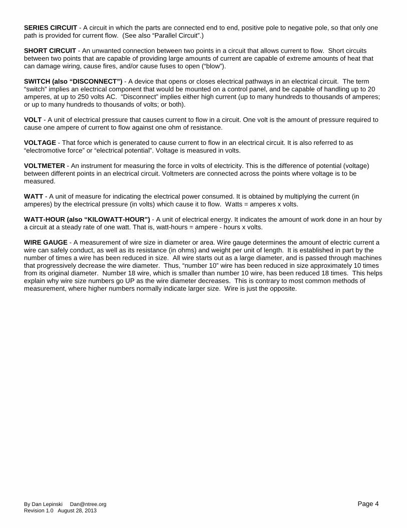
SERIES CIRCUIT - A circuit in which the parts are connected end to end, positive pole to negative pole, so that only one path is provided for current flow. (See also “Parallel Circuit”.) SHORT CIRCUIT - An unwanted connection between two points in a circuit that allows current to flow. Short circuits between two points that are capable of providing large amounts of current are capable of extreme amounts of heat that can damage wiring, cause fires, and/or cause fuses to open (“blow”). SWITCH (also “DISCONNECT”) - A device that opens or closes electrical pathways in an electrical circuit. The term “switch” implies an electrical component that would be mounted on a control panel, and be capable of handling up to 20 amperes, at up to 250 volts AC. “Disconnect” implies either high current (up to many hundreds to thousands of amperes; or up to many hundreds to thousands of volts; or both). VOLT - A unit of electrical pressure that causes current to flow in a circuit. One volt is the amount of pressure required to cause one ampere of current to flow against one ohm of resistance. VOLTAGE - That force which is generated to cause current to flow in an electrical circuit. It is also referred to as “electromotive force” or “electrical potential”. Voltage is measured in volts. VOLTMETER - An instrument for measuring the force in volts of electricity. This is the difference of potential (voltage) between different points in an electrical circuit. Voltmeters are connected across the points where voltage is to be measured. WATT - A unit of measure for indicating the electrical power consumed. It is obtained by multiplying the current (in amperes) by the electrical pressure (in volts) which cause it to flow. Watts = amperes x volts. WATT-HOUR (also “KILOWATT-HOUR”) - A unit of electrical energy. It indicates the amount of work done in an hour by a circuit at a steady rate of one watt. That is, watt-hours = ampere - hours x volts. WIRE GAUGE - A measurement of wire size in diameter or area. Wire gauge determines the amount of electric current a wire can safely conduct, as well as its resistance (in ohms) and weight per unit of length. It is established in part by the number of times a wire has been reduced in size. All wire starts out as a large diameter, and is passed through machines that progressively decrease the wire diameter. Thus, “number 10” wire has been reduced in size approximately 10 times from its original diameter. Number 18 wire, which is smaller than number 10 wire, has been reduced 18 times. This helps explain why wire size numbers go UP as the wire diameter decreases. This is contrary to most common methods of measurement, where higher numbers normally indicate larger size. Wire is just the opposite.
By Dan Lepinski [email protected] Page 5 Revision 1.0 August 28, 2013
A Discussion About Fuses for Your Solar Car
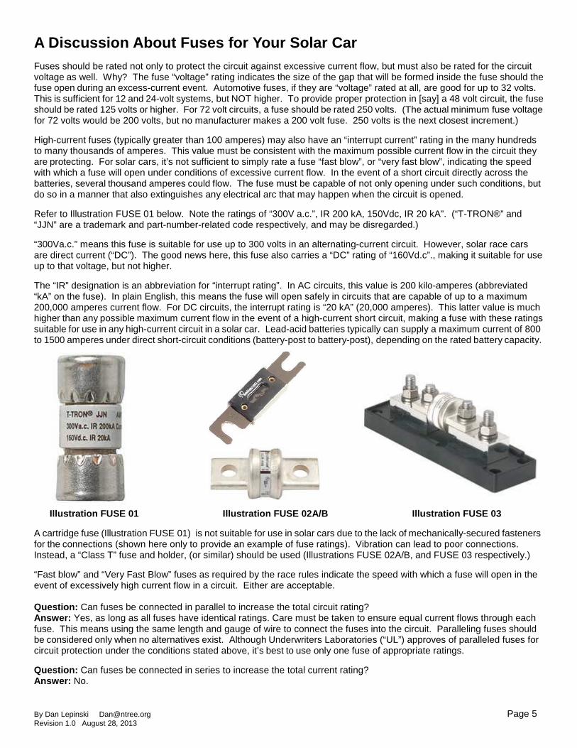
Fuses should be rated not only to protect the circuit against excessive current flow, but must also be rated for the circuit voltage as well. Why? The fuse “voltage” rating indicates the size of the gap that will be formed inside the fuse should the fuse open during an excess-current event. Automotive fuses, if they are “voltage” rated at all, are good for up to 32 volts. This is sufficient for 12 and 24-volt systems, but NOT higher. To provide proper protection in [say] a 48 volt circuit, the fuse should be rated 125 volts or higher. For 72 volt circuits, a fuse should be rated 250 volts. (The actual minimum fuse voltage for 72 volts would be 200 volts, but no manufacturer makes a 200 volt fuse. 250 volts is the next closest increment.) High-current fuses (typically greater than 100 amperes) may also have an “interrupt current” rating in the many hundreds to many thousands of amperes. This value must be consistent with the maximum possible current flow in the circuit they are protecting. For solar cars, it’s not sufficient to simply rate a fuse “fast blow”, or “very fast blow”, indicating the speed with which a fuse will open under conditions of excessive current flow. In the event of a short circuit directly across the batteries, several thousand amperes could flow. The fuse must be capable of not only opening under such conditions, but do so in a manner that also extinguishes any electrical arc that may happen when the circuit is opened. Refer to Illustration FUSE 01 below. Note the ratings of “300V a.c.”, IR 200 kA, 150Vdc, IR 20 kA”. (“T-TRON®” and “JJN” are a trademark and part-number-related code respectively, and may be disregarded.) “300Va.c.” means this fuse is suitable for use up to 300 volts in an alternating-current circuit. However, solar race cars are direct current (“DC”). The good news here, this fuse also carries a “DC” rating of “160Vd.c”., making it suitable for use up to that voltage, but not higher. The “IR” designation is an abbreviation for “interrupt rating”. In AC circuits, this value is 200 kilo-amperes (abbreviated “kA” on the fuse). In plain English, this means the fuse will open safely in circuits that are capable of up to a maximum 200,000 amperes current flow. For DC circuits, the interrupt rating is “20 kA” (20,000 amperes). This latter value is much higher than any possible maximum current flow in the event of a high-current short circuit, making a fuse with these ratings suitable for use in any high-current circuit in a solar car. Lead-acid batteries typically can supply a maximum current of 800 to 1500 amperes under direct short-circuit conditions (battery-post to battery-post), depending on the rated battery capacity.
Illustration FUSE 01 Illustration FUSE 02A/B Illustration FUSE 03 A cartridge fuse (Illustration FUSE 01) is not suitable for use in solar cars due to the lack of mechanically-secured fasteners for the connections (shown here only to provide an example of fuse ratings). Vibration can lead to poor connections. Instead, a “Class T” fuse and holder, (or similar) should be used (Illustrations FUSE 02A/B, and FUSE 03 respectively.) “Fast blow” and “Very Fast Blow” fuses as required by the race rules indicate the speed with which a fuse will open in the event of excessively high current flow in a circuit. Either are acceptable. Question: Can fuses be connected in parallel to increase the total circuit rating? Answer: Yes, as long as all fuses have identical ratings. Care must be taken to ensure equal current flows through each fuse. This means using the same length and gauge of wire to connect the fuses into the circuit. Paralleling fuses should be considered only when no alternatives exist. Although Underwriters Laboratories (“UL”) approves of paralleled fuses for circuit protection under the conditions stated above, it’s best to use only one fuse of appropriate ratings. Question: Can fuses be connected in series to increase the total current rating? Answer: No.

By Dan Lepinski [email protected] Page 6 Revision 1.0 August 28, 2013
Switches and Disconnects
Ensure the switch or disconnect ratings are sufficient for your operating voltage and current. Teams I saw were aware of the current ratings, but not the voltage ratings.
I observed switches and disconnects on cars that were rated for the current, but at a voltage lower than that which they were used. Should they have needed to be opened in the event of an electrical malfunction, some may not have been able to successfully and safely do so under conditions of excessive electrical current flow.
Switches must be rated not only for the maximum current (see “AMPERES”) that will flow through them, but also for the highest voltage in the circuit to which they are connected (plus a safety factor), AND be rated for the type of power source in the circuit (“AC” or “DC”). Some switches and disconnects carry ratings for both AC and DC. Please note that a switch rated for 250 volts “AC” is NOT suitable for use at 250 volts “DC”. A “DC” rating will always be lower than an “AC” rating because DC power flow is continuous (it never goes to zero volts), whereas an AC power flow passes through zero volts twice each cycle. This “pass through zero” aspect to AC voltage and current makes it easier to quench an electrical arc, and thus allows for higher voltage ratings. AC-rated switches can be used for DC applications, but at lower voltages. The “how much lower” doesn’t have a fixed rule, but 1/3 of the AC voltage is generally acceptable for a DC rating.
Switches often have one current rating at a lower voltage, and a different (lesser) current rating at a higher voltage. Note Illustration SWITCH 01.
Below are examples of three disconnects that are representative of units I saw in the 2013 Solar Car Challenge race. Although the contact current ratings may have been adequate for the motor circuit in which they were used, the voltage ratings in some cases were too low for the circuit voltage.
Why is this important? If a high-current incident occurred during the race, such as a short-circuited motor controller, where excessive current was flowing, but was not of sufficient magnitude to blow the fuse, disconnect switches with a voltage rating lower than the battery voltage would not necessarily have contacts that would open with a sufficient gap distance between them to prevent a continuing electrical arc. Under such conditions, the flow of current could continue. At the same time, heat from the arc within the disconnect could cause it to melt - or worse - catch fire. Illustration SWITCH 01
You cannot tell “appropriate” switches apart from “inappropriate” switches simply by looking at them. All three of the example switches below look robust, like they would do the job. This isn’t the case.
Manufacturer-rated for 1000 amperes for 10 seconds at 12 volts, or 500 amperes at 24 volts for 10 seconds.
This unit is NOT appropriate for circuits over 12 volts DC.
http://www.go2marine.com/product/384830F/hella-marine-battery-master-switch-on-off-disconnect-50-amp.html
Manufacturer-rated for 480 amperes continuously, up to 32 volts. (No time limit was listed in the specifications.) This unit is NOT appropriate for circuits over 32 volts DC.
http://www.perko.com/catalog/category/battery_switches/
Manufacturer-rated for a continuous current of 275 amps, and 455 amps for 10 seconds, up to 48 volts.
Suitable for a 48 volt solar car electric system. http://www.bepmarine.com/home-mainmenu-8/product-319/701-master-battery-switch

By Dan Lepinski [email protected] Page 7 Revision 1.0 August 28, 2013
Crimps, Lugs, and Wire-Splicing Devices Refer to the following illustrations:
Illustration LUGS 01: “Ring” Lugs Illustration LUGS 02: “Spade” Lugs Illustration LUGS 03: “Terminal” Lugs Illustration LUGS 04: Lug Crimp Tool Illustration LUGS 05: Combination Wire Stripper and Lug Crimp Tool
Illustration LUGS 01 Illustration LUGS 02 Illustration LUGS 03 Ring Lugs Spade Lugs Terminal Lugs
Illustration LUGS 04 Illustrati on LUGS 05 Crimp Tool Combination Wire Stripper and Crimp Tool The plastic collar on the “neck” of each lug helps prevent it from contacting an adjoining lug in a barrier strip (also called a “terminal block”). See Illustrations LUGS 18, LUGS 19A, and LUGS 19B on page 10 for examples of barrier strips. Ring lugs are the most secure method for attaching wires to terminal blocks and other points in a solar car, but these require removing and replacing the screw each time. Spade lugs are easier to insert and remove, but can become disconnected if the terminal block hardware is loose. Terminal lugs are commonly used for joining one wire to another. Refer to Illustrations “LUGS 04” and “LUGS 05”. These are “crimp tools”. Crimp tools are used for compressing the lug neck around the wire. Either tool shown is acceptable, but the tool shown in Illustration LUGS 04 will generally provide a tighter crimp by virtue of its design and better leverage. So which to use? Both! The tool in Illustration LUGS 05 makes removal of insulation very easy. The other tool can be used to crimp the wire into the lug neck. Rule #1: Make sure the lug size matches the wire size and the attaching hardware size! Rule #2: Use the proper tools for crimping the lugs to the wire. Rule #3: Practice making crimps before working on the car wiring!. Rule #4: Test your crimped connections. How? Use a “pull test”. For the wire gauges below, you should be able apply the force shown in Table “LUGS 01” to the wire and lug without the wire separating from the lug. This is a military-grade rating, but given the potentially harsh environment of the solar cars, is highly recommended for safety and reliability.
Table “LUGS 01” Wire Gauge Pull Test Requirements
22 15 lb
20 19 lb
18 38 lb
16 50 lb
14 70 lb
12 110 lb
10 150 lb
By Dan Lepinski [email protected] Page 8 Revision 1.0 August 28, 2013
Tips for Proper Attachment of Wire Lugs
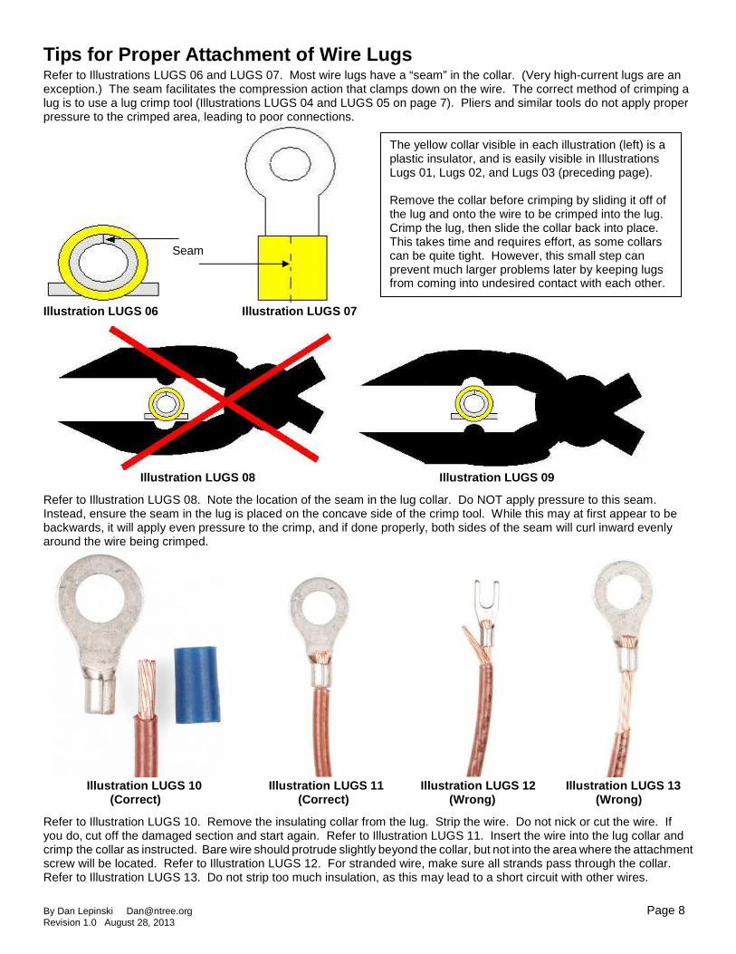
Refer to Illustrations LUGS 06 and LUGS 07. Most wire lugs have a “seam” in the collar. (Very high-current lugs are an exception.) The seam facilitates the compression action that clamps down on the wire. The correct method of crimping a lug is to use a lug crimp tool (Illustrations LUGS 04 and LUGS 05 on page 7). Pliers and similar tools do not apply proper pressure to the crimped area, leading to poor connections.
Illustration LUGS 06 Illust ration LUGS 07
Illustration LUGS 08 Illustration LUGS 09
Refer to Illustration LUGS 08. Note the location of the seam in the lug collar. Do NOT apply pressure to this seam. Instead, ensure the seam in the lug is placed on the concave side of the crimp tool. While this may at first appear to be backwards, it will apply even pressure to the crimp, and if done properly, both sides of the seam will curl inward evenly around the wire being crimped.
Illustration LUGS 10 Illustration LUGS 11 Illustration LUGS 12 Illustration LUGS 13 (Correct) (Correct) (Wrong) (Wrong)
Refer to Illustration LUGS 10. Remove the insulating collar from the lug. Strip the wire. Do not nick or cut the wire. If you do, cut off the damaged section and start again. Refer to Illustration LUGS 11. Insert the wire into the lug collar and crimp the collar as instructed. Bare wire should protrude slightly beyond the collar, but not into the area where the attachment screw will be located. Refer to Illustration LUGS 12. For stranded wire, make sure all strands pass through the collar. Refer to Illustration LUGS 13. Do not strip too much insulation, as this may lead to a short circuit with other wires.
Seam
The yellow collar visible in each illustration (left) is a plastic insulator, and is easily visible in Illustrations Lugs 01, Lugs 02, and Lugs 03 (preceding page). Remove the collar before crimping by sliding it off of the lug and onto the wire to be crimped into the lug. Crimp the lug, then slide the collar back into place. This takes time and requires effort, as some collars can be quite tight. However, this small step can prevent much larger problems later by keeping lugs from coming into undesired contact with each other.
By Dan Lepinski [email protected] Page 9 Revision 1.0 August 28, 2013
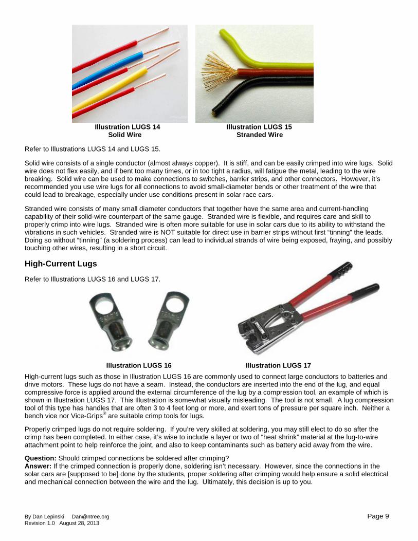
Illustration L UGS 14 Illustrati on LUGS 15 Solid W ire Stranded Wire Refer to Illustrations LUGS 14 and LUGS 15. Solid wire consists of a single conductor (almost always copper). It is stiff, and can be easily crimped into wire lugs. Solid wire does not flex easily, and if bent too many times, or in too tight a radius, will fatigue the metal, leading to the wire breaking. Solid wire can be used to make connections to switches, barrier strips, and other connectors. However, it’s recommended you use wire lugs for all connections to avoid small-diameter bends or other treatment of the wire that could lead to breakage, especially under use conditions present in solar race cars. Stranded wire consists of many small diameter conductors that together have the same area and current-handling capability of their solid-wire counterpart of the same gauge. Stranded wire is flexible, and requires care and skill to properly crimp into wire lugs. Stranded wire is often more suitable for use in solar cars due to its ability to withstand the vibrations in such vehicles. Stranded wire is NOT suitable for direct use in barrier strips without first “tinning” the leads. Doing so without “tinning” (a soldering process) can lead to individual strands of wire being exposed, fraying, and possibly touching other wires, resulting in a short circuit. High-Current Lugs
Refer to Illustrations LUGS 16 and LUGS 17. Illustra tion LUGS 16 Illustration LUGS 17
High-current lugs such as those in Illustration LUGS 16 are commonly used to connect large conductors to batteries and drive motors. These lugs do not have a seam. Instead, the conductors are inserted into the end of the lug, and equal compressive force is applied around the external circumference of the lug by a compression tool, an example of which is shown in Illustration LUGS 17. This Illustration is somewhat visually misleading. The tool is not small. A lug compression tool of this type has handles that are often 3 to 4 feet long or more, and exert tons of pressure per square inch. Neither a bench vice nor Vice-Grips® are suitable crimp tools for lugs.
Properly crimped lugs do not require soldering. If you’re very skilled at soldering, you may still elect to do so after the crimp has been completed. In either case, it’s wise to include a layer or two of “heat shrink” material at the lug-to-wire attachment point to help reinforce the joint, and also to keep contaminants such as battery acid away from the wire.
Question: Should crimped connections be soldered after crimping? Answer: If the crimped connection is properly done, soldering isn’t necessary. However, since the connections in the solar cars are [supposed to be] done by the students, proper soldering after crimping would help ensure a solid electrical and mechanical connection between the wire and the lug. Ultimately, this decision is up to you.

By Dan Lepinski [email protected] Page 10 Revision 1.0 August 28, 2013
Barrier Strips (Also called “Terminal Strips”)
Refer to Illustration LUGS 18. Illustration LUGS 18 depicts a “barrier strip”. Barrier strips are made of a very durable plastic, with sets of pairs of screws. One screw is connected to its counterpart with a strip of metal (refer to Illustrations LUGS 19A and LUGS 19B).
Illustrat ion LUGS 18
Illustration LUGS 19A I llustration LUGS 19B Barrier strips are available in a variety of sizes and lengths, and are an excellent method for establishing connections in a solar car. Barrier strips also provide an easy means for creating “test points” for measuring various circuits. Race rules require that all electrical connections be protected from accidental contact. An insulating cover of fiberglass circuit board material or heavy plastic can be fabricated and attached using “stand-offs” at the ends of the barrier strip. Other suitable protective methods can also be devised. Refer to Illustration LUGS 20. This shows how a barrier strip could be used to distribute power from your auxiliary battery to various loads in your solar car.
Connections to barrier strips can be made with ring lugs or spade lugs. Though the latter are easier to use, care should be taken to ensure all of screws are properly tightened to prevent bad or short-circuit connections. A common “buss” can be constructed using connection strips such as shown in Illustrations LUGS 21A and LUGS 21B. . Illustration LUG S 21A Illustration LUGS 21B
Illustration LUGS 20

By Dan Lepinski [email protected] Page 11 Revision 1.0 August 28, 2013
What is a Maximum Power Point Tracker (“MPPT”) and Why Is It Useful? A Maximum Power Point Tracker (“MPPT”) is like gears in your transmission, or the gears on a 10 or 15-speed bicycle. They can change a faster rate of rotation to a lower rate of rotation, or just the opposite .. as needed. Refer to Illustration GEAR 01 (below). Let’s say gear ‘A’ is the gear that’s connected to a motor, and gear ‘B’ is the gear connected to the wheels. We would take the energy output from gear ‘B’. Let’s next say driven gear ‘A’ represents your solar panels, and it’s spinning more rapidly (is higher voltage) than needed. By coupling gear ‘A’ to gear ‘B’ in this manner, gear ‘B’ turns more slowly than gear ‘A’, but provides more “torque” (“twist”) than gear ‘A’. By electronically decreasing the output voltage, a MPPT will increase the available current by the same percentage the voltage decreases. Half the voltage output compared to the input = double the current compared to the input current. Remember, it’s amperage (amount of electricity) flowing into a battery that determines the quantity of energy being put into that battery. Voltage pushes the current .. but it’s the current that charges the battery. You could connect the solar panels directly to your batteries, but much energy would be lost. Solar panels are “current limited” in the maximum amperage they can generate. For instance, if five solar panels (each rated 36 volts output at 6 amperes) were connected in series, you’d have 36 volts x 5 = 180 volts at 6 amperes available. 180 volts x 6 amperes is 1,080 watts. If you connected these directly to [say] a 48 volt battery, the battery voltage would force the solar panels down to 48 volts, and 6 amperes would be flowing into the battery. 48 volts x 6 amperes equals 288 watts. The solar panels wouldn’t be affected by this direct connection, but you’d be giving up 792 watts, for an efficiency of only 26.7%!
=
180 RPM @ 10 lb/feet 90 RPM @ 20 lb/feet 180V @ 6 amps 48V @ 22.5 amps Many teachers and students were surprised to learn DC voltage can be electronically decreased in this manner. Most thought such reductions could only be done with alternating current and transformers. Many were also under the impression MPPT units wasted 30% or more of the energy going in. This is NOT correct. Modern MPPT units are easily capable of 95-98% efficiency. This means only 2-5% of the energy is lost changing a higher voltage at lower current to lower voltage and higher current. That’s a BIG improvement over 26.7%! Do the math. Gear ‘B’ is spinning more slowly than gear ‘A’, but offers more “torque”. The same happens in a maximum power point tracker .. but electronically, where “RPM” equates to voltage, and “torque” equates to amperage. Thus, 180 volts at 6 amperes (180V x 6A) = 1,080 watts. 48 volts at 22.5 amperes also equals 1,080 watts. In actual practice, the MPPT output power would be slightly less than the input power owing to the small efficiency losses within the MPPT. Thus in real life, if 1,080 watts were going in, you should expect 1,020 to 1,060 watts output from the tracker. Most MPPT units today also incorporate a battery charge controller to prevent the battery from being over-charged, which if allowed to happen, would lead to damage to or destruction of the battery. Exploding batteries are NOT fun!
A B
Illustration GEAR 01
Illustration GEAR 02

By Dan Lepinski [email protected] Page 12 Revision 1.0 August 28, 2013
Circuits: “Normal” Circuit. “Open” Circuit. “Sho rt” Circuit. Often, when no electricity was present in a circuit (and should be), I heard students and teachers alike refer to that condition as a “short circuit”. This is not correct. See the illustrations and definitions below.
“Normal” Circuit
This is a “normal” circuit. Electricity flows from battery, through the wires to the “load”, which in this example is a light bulb. Current flow is indicated by the red arrows. (For the electrical purists, yes, I know this is “backwards”. Current flow is the movement of electrons, and actually occurs from “minus” to “plus” in the circuit.) Two wires are needed for a complete circuit -- one “pushing” the electrons; the other “pulling them”. Electrons can’t simply “spill out of a wire” the way water comes out of a garden hose.
“Open” Circuit
This is an “open” circuit. The connection between the battery and the light bulb is broken, like a highway where a bridge has been washed away. No current flows from the battery, and the light bulb doesn’t illuminate. An open circuit prevents loads from operating, but is otherwise not generally dangerous unless the voltage is 50V or more, and inadvertent contact is made with both the positive and negative conductors at the same time.
“Short” Circuit
This is a “short” circuit. In this example, an unwanted path for current to flow exists from the battery positive to the battery negative. This unwanted path bypasses the light bulb, so the light bulb doesn’t illuminate. The battery and wires may get very hot. If there were a fuse of appropriate ratings installed in this circuit at the battery, the fuse would “open”, and the flow of electric current would cease. Of “open” and “short” circuits, short circuits are more dangerous and potentially damaging, particularly if they occur in circuits where very high currents can flow. Circuit voltage and resistance will determine the maximum current flow when a short-circuit exists. If the short occurs in a main power circuit, such as directly from the battery “positive” to the battery negative”, the current would be limited only by the wire and connection resistances and the maximum short-circuit current flow of the battery.
By Dan Lepinski [email protected] Page 13 Revision 1.0 August 28, 2013
Final Comments WIRING and SCHEMATICS MUST MATCH. This goes without saying, and is required by the Race Rules. However, more than once, an electrical system had been modified in cars at the last minute, and the schematics in the possession of the teams weren’t updated to match. This was only discovered when cars developed problems on the race course, and made diagnosis efforts much more difficult. Documentation submitted for Scrutineering may have been correct, but copies in teams’ possession sometimes were not. Install a “Main” Fuse for Each Battery System Race rules require a fuse for your main propulsion battery. The same should also be done for your auxiliary battery. Refer to Illustration LUGS 20 (page 10). Connect a wire of appropriate size for the total amperage to be drawn from your auxiliary battery. Attach the wire from the battery positive to the “main” fuse, and from the main fuse to the other circuits. One fuse for all circuits often isn’t appropriate. Fuses protect the wiring in the event of a short circuit. Connect as follows: Battery -> Fuse -> Distribution. Then use additional smaller fuses for each circuit as appropriate, with all of them connected to the common distribution point as needed (as in Illustration LUGS 20, page 10). Barrier strips will facilitate such connections. If desired, a switch could then be connected in line with the auxiliary battery “main” fuse on the wiring side AWAY from the battery to serve as a “Master On/Off” function for all of your auxiliary loads. Soldering Solder should flow onto wires and connectors the same way room-temperature butter flows onto warm toast. First, with a soldering iron of adequate size and wattage for the task, heat the conductors that are to be connected, THEN apply a small amount of solder and allow it to flow. If the solder doesn’t melt, or if it sits on the wires without flowing into them, then the wires aren’t hot (and/or clean) enough. Learn and practice proper soldering techniques BEFORE you begin working on your solar race car. A properly soldered connection between two wires will be stronger than either of the wires by itself. Secure ALL Wires and Connections from Vibration, et c.! More securement is better than too little. I saw wiring in some cars that resembled fishing line on an open-faced reel after a bad “backlash”. This not only makes assembly more difficult, it can lead to misidentification of wires. Wire runs - Shorter is Better. On one car, I saw wiring from the main “propulsion” battery that was connected to the battery positive, then to the main fuse, then back to the rear of the car to an unused lug on the motor controller, then forward to the two safety disconnect switches, and finally back to “live” lugs on the motor controller. If done more sensibly, this wire would have been half as long, with half the loss, half the weight, and half the expense. Think before you make your connections. Insulation. Use wire with very durable insulation, especially for the high-current conductors. I observed one car where the motor wires were made from old welding cable with soft rubber insulation. By the second day, the insulation was damaged where it rubbed against hardware on the car frame, and required tape and nylon ties to prevent unwanted electrical contact with the frame. (Such electrical contact is against the Race Rules as well). Batteries. Learn how to use battery voltage to estimate the approximate state of charge. A fully charged 12 volt battery at 77°F (25°C) will measure approximately 12.65 volts with no load applied. Conversely, 12 volt batteries are dead at 10.5V with no load applied. There’s a condition known as a “surface charge” that will cause freshly charged batteries to read above 12.65 volts, sometimes by up to a volt or more. The surface charge will dissipate within roughly 24 hours of a battery being charged, or within minutes of it being connected to a load. Meters and Instrumentation If you don’t know how to use a voltmeter, LEARN! Learn what the various readings mean. Learn what the various ranges mean. There are countless tutorials available on this subject.
By Dan Lepinski [email protected] Page 14 Revision 1.0 August 28, 2013
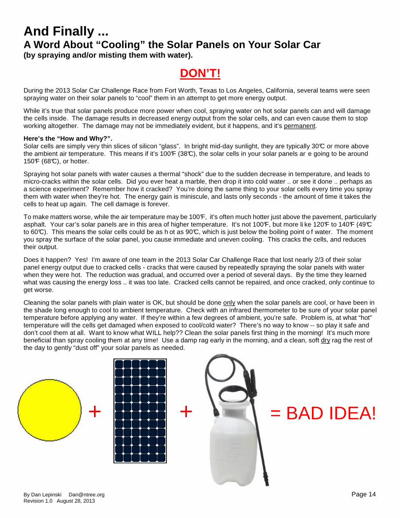
And Finally ... A Word About “Cooling” the Solar Panels on Your Sol ar Car (by spraying and/or misting them with water).
DON’T! During the 2013 Solar Car Challenge Race from Fort Worth, Texas to Los Angeles, California, several teams were seen spraying water on their solar panels to “cool” them in an attempt to get more energy output.
While it’s true that solar panels produce more power when cool, spraying water on hot solar panels can and will damage the cells inside. The damage results in decreased energy output from the solar cells, and can even cause them to stop working altogether. The damage may not be immediately evident, but it happens, and it’s permanent.
Here’s the “How and Why?”. Solar cells are simply very thin slices of silicon “glass”. In bright mid-day sunlight, they are typically 30°C or more above the ambient air temperature. This means if it’s 100°F (38°C), the solar cells in your solar panels ar e going to be around 150°F (68°C), or hotter.
Spraying hot solar panels with water causes a thermal “shock” due to the sudden decrease in temperature, and leads to micro-cracks within the solar cells. Did you ever heat a marble, then drop it into cold water .. or see it done .. perhaps as a science experiment? Remember how it cracked? You’re doing the same thing to your solar cells every time you spray them with water when they’re hot. The energy gain is miniscule, and lasts only seconds - the amount of time it takes the cells to heat up again. The cell damage is forever.
To make matters worse, while the air temperature may be 100°F, it’s often much hotter just above the pavement, particularly asphalt. Your car’s solar panels are in this area of higher temperature. It’s not 100°F, but more li ke 120°F to 140°F (49°C to 60°C). This means the solar cells could be as h ot as 90°C, which is just below the boiling point o f water. The moment you spray the surface of the solar panel, you cause immediate and uneven cooling. This cracks the cells, and reduces their output.
Does it happen? Yes! I’m aware of one team in the 2013 Solar Car Challenge Race that lost nearly 2/3 of their solar panel energy output due to cracked cells - cracks that were caused by repeatedly spraying the solar panels with water when they were hot. The reduction was gradual, and occurred over a period of several days. By the time they learned what was causing the energy loss .. it was too late. Cracked cells cannot be repaired, and once cracked, only continue to get worse.
Cleaning the solar panels with plain water is OK, but should be done only when the solar panels are cool, or have been in the shade long enough to cool to ambient temperature. Check with an infrared thermometer to be sure of your solar panel temperature before applying any water. If they’re within a few degrees of ambient, you’re safe. Problem is, at what “hot” temperature will the cells get damaged when exposed to cool/cold water? There’s no way to know -- so play it safe and don’t cool them at all. Want to know what WILL help?? Clean the solar panels first thing in the morning! It’s much more beneficial than spray cooling them at any time! Use a damp rag early in the morning, and a clean, soft dry rag the rest of the day to gently “dust off” your solar panels as needed.
+ + = BAD IDEA!