solar array structures for 300 kw-class spacecraft - … array structures for 300 kw-class...
TRANSCRIPT
Solar Array Structures for 300 kW-Class Spacecraft
Richard Pappa, Geoff Rose, Troy Mann, Jay Warren
NASA Langley Research Center, Hampton, VA
Martin Mikulas
National Institute of Aerospace, Hampton, VA
Tom Kerslake, Tom Kraft
NASA Glenn Research Center, Cleveland, OH
Jeremy Banik
Air Force Research Laboratory, Space Vehicles Directorate, Kirtland AFB, NM
Space Power Workshop, April 24, 2013
https://ntrs.nasa.gov/search.jsp?R=20140000360 2018-05-31T07:46:37+00:00Z
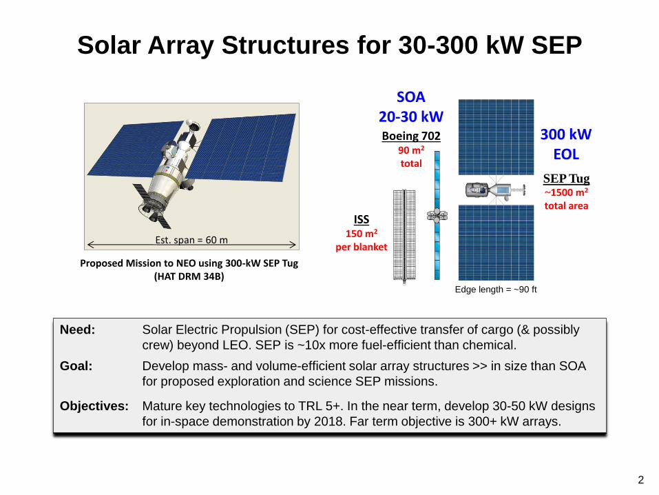
Solar Array Structures for 30-300 kW SEP
ISS 150 m2
per blanket
SEP Tug ~1500 m2
total area
Boeing 702 90 m2
total
Proposed Mission to NEO using 300-kW SEP Tug (HAT DRM 34B)
Est. span = 60 m
Need: Solar Electric Propulsion (SEP) for cost-effective transfer of cargo (& possibly
crew) beyond LEO. SEP is ~10x more fuel-efficient than chemical.
Goal: Develop mass- and volume-efficient solar array structures >> in size than SOA
for proposed exploration and science SEP missions.
Objectives: Mature key technologies to TRL 5+. In the near term, develop 30-50 kW designs
for in-space demonstration by 2018. Far term objective is 300+ kW arrays.
300 kW EOL
SOA 20-30 kW
2
Edge length = ~90 ft

ISS Solar Array Blanket – 150 m2 A 300 kW solar array needs ~10x this area
3

Assumptions/Goals for 300 kW-Class Solar Arrays
Power• 450 kW BOL
• 300 kW EOL, assuming 33% worst-case degradation
Deployed area (2 wings) 1500 m2, assuming 300 W/m2 BOL or 200 W/m2 EOL
Deployed stiffness > 0.05 Hz
Deployed strength > 0.1 g (chemical stage thrusting in some SEP missions)
Specific power > 120 W/kg BOL (> 100 W/kg EOL), including SADA
Stowed volume > 40 kW/m3 BOL
Voltage 160-300+ V
Blanket Flexible substrate, assuming < 1 kg/m2 areal density, 0.030” thick
Planar vs concentrators Assuming planar arrays will be used
Deployment reliability Goal: “100%” – Deployment is highest perceived project risk
4
ATK MegaFlex 30-50 kW Prototype
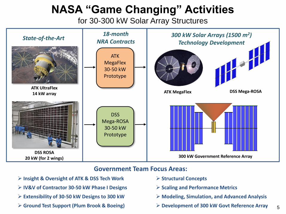
NASA “Game Changing” Activities for 30-300 kW Solar Array Structures
State-of-the-Art 18-month
NRA Contracts
ATK UltraFlex 14 kW array
DSS ROSA 20 kW (for 2 wings)
ATK MegaFlex DSS Mega-ROSA
300 kW Government Reference Array
300 kW Solar Arrays (1500 m2) Technology Development
DSS Mega-ROSA
30-50 kW Prototype
5
Insight & Oversight of ATK & DSS Tech Work
IV&V of Contractor 30-50 kW Phase I Designs
Extensibility of 30-50 kW Designs to 300 kW
Ground Test Support (Plum Brook & Boeing)
Structural Concepts
Scaling and Performance Metrics
Modeling, Simulation, and Advanced Analysis
Development of 300 kW Govt Reference Array
Government Team Focus Areas:

Structures for Large Solar Arrays
• Challenge - Scaling up solar array power by an
order-of-magnitude to ~300 kW requires game
changing advances in
structural mass fraction
packaging, and
deployment reliability
• Goal/Objective – Develop and validate array
structural concepts with a
structural mass fraction of 0.2 or lower and a
power/packaging volume ~ 25 to 40 kW/m3
• Need rational method to compare arrays on a level
playing field
• Major question is how reliably results scale
6
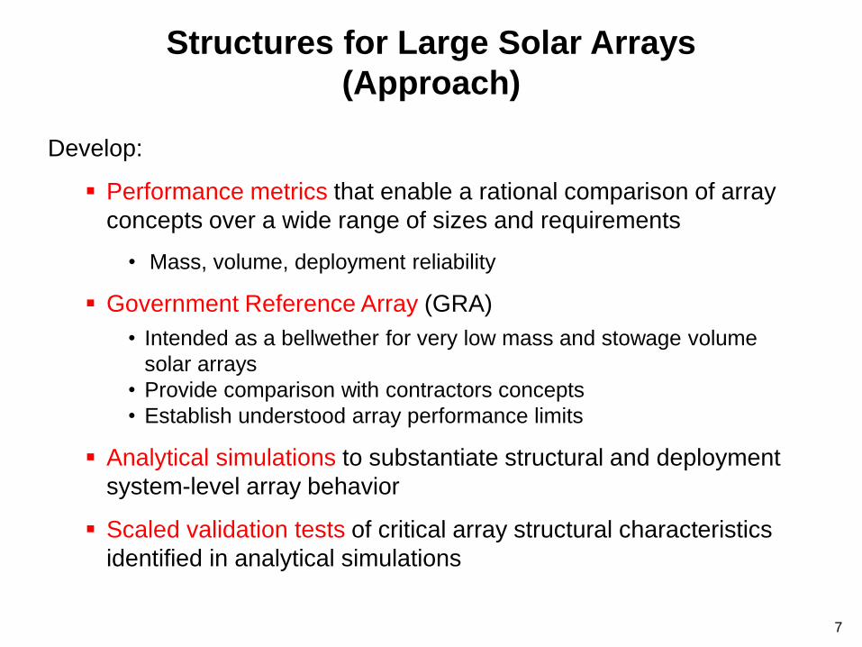
Develop:
Performance metrics that enable a rational comparison of array
concepts over a wide range of sizes and requirements
• Mass, volume, deployment reliability
Government Reference Array (GRA)
• Intended as a bellwether for very low mass and stowage volume
solar arrays
• Provide comparison with contractors concepts
• Establish understood array performance limits
Analytical simulations to substantiate structural and deployment
system-level array behavior
Scaled validation tests of critical array structural characteristics
identified in analytical simulations
7
Structures for Large Solar Arrays
(Approach)

Major Challenge to Achieving High Structural
Efficiency is the Compact Packaging Requirement
250 kW
4 Launches + EVA
8 Winglets
300 kW
1 Launch, No EVA
16 Winglets
8 8
250 kW
4 Launches + EVA
8 Winglets
300 kW
1 Launch, No EVA
16 Winglets
9
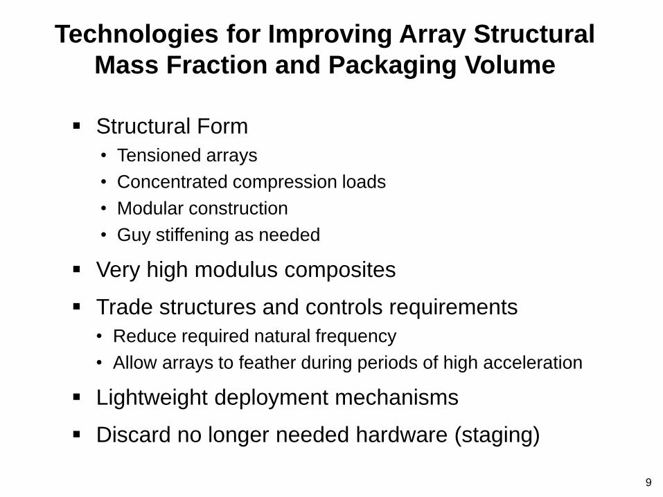
Technologies for Improving Array Structural
Mass Fraction and Packaging Volume
Structural Form
• Tensioned arrays
• Concentrated compression loads
• Modular construction
• Guy stiffening as needed
Very high modulus composites
Trade structures and controls requirements
• Reduce required natural frequency
• Allow arrays to feather during periods of high acceleration
Lightweight deployment mechanisms
Discard no longer needed hardware (staging)

10
Vein
Midrib
Stalk
Stem
Blade
Structure of a Leaf
Good Structural Form is Key to Structural Efficiency
Channel (concentrate) all Loads Into one Major
Support Structure
16 Winglets
Trunk
Structure
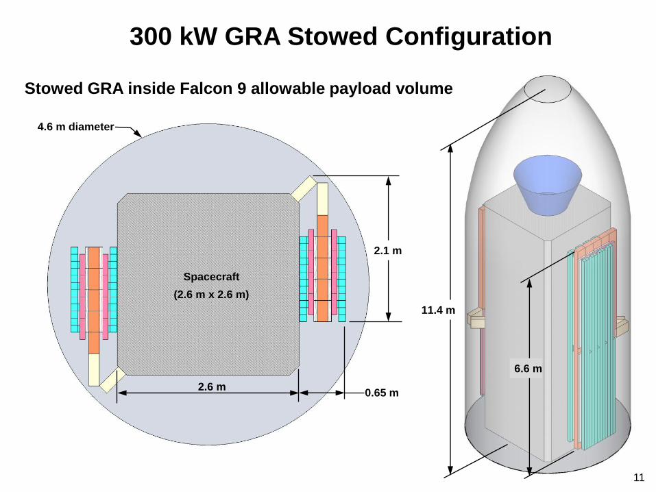
300 kW GRA Stowed Configuration
Stowed GRA inside Falcon 9 allowable payload volume
4.6 m diameter
2.1 m
0.65 m 2.6 m
6.6 m
11.4 m
Spacecraft
(2.6 m x 2.6 m)
11

300 kW GRA Deployment Sequence
Stowed Configuration Wings Unfolded
12
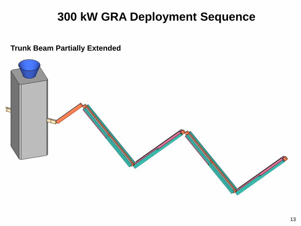
Trunk Beam Partially Extended
300 kW GRA Deployment Sequence
13

Trunk Beam Fully Extended
Blanket Tube Stacks Initially
Vertical
300 kW GRA Deployment Sequence
14

Begin Winglet Deployment
Blanket Tube Stacks Rotate
to Horizontal Position
300 kW GRA Deployment Sequence
15
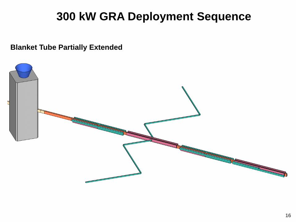
Blanket Tube Partially Extended
300 kW GRA Deployment Sequence
16
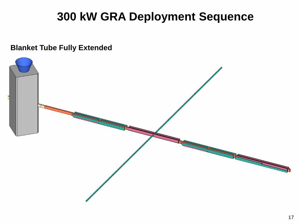
Blanket Tube Fully Extended
300 kW GRA Deployment Sequence
17
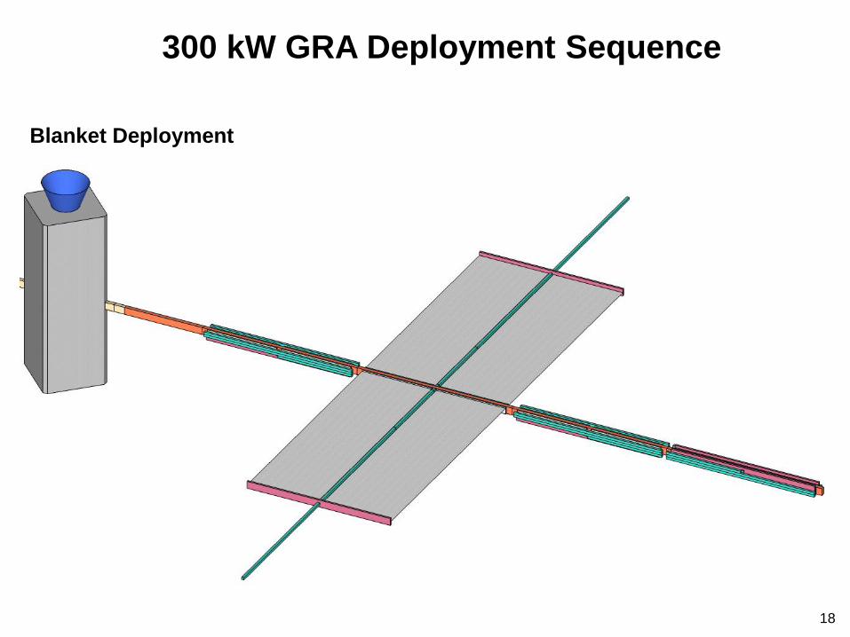
Blanket Deployment
300 kW GRA Deployment Sequence
18
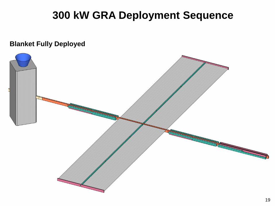
Blanket Fully Deployed
300 kW GRA Deployment Sequence
19

Single Winglet Physical Properties
16 m
3 m
Blankets
Tension = 88.96 N (20 lbs)
t = 0.762 mm (0.03 in)
E = 3.45 GPa (0.5 Msi)
ρ = 1281.6 kg/m3 (0.0463 lb/in3)
End Support Beam (circular solid)
R = 76.2 mm (3.0 in)
E = 140 GPa (20.3 Msi)
ρ = 64.0 kg/m3 (0.0023 lb/in3)
Blanket Tube (square tube)
w = 101.6 mm (4.0 in)
h = 101.6 mm (4.0 in)
t = 1.27 mm (0.05 in)
E = 140 GPa (20.3 Msi)
ρ = 1993.0 kg/m3 (0.072 lb/in3)
Trunk Beam (rectangular tube)
w = 152.4 mm (6.0 in)
h = 304.8 mm (12.0 in)
t = 1.524 mm (0.06 in)
E = 140 GPa (20.3 Msi)
ρ = 1993.0 kg/m3 (0.072 lb/in3)
20

21
Tension Stiffening Could be Added to Winglets or
Trunk Beam as Necessary
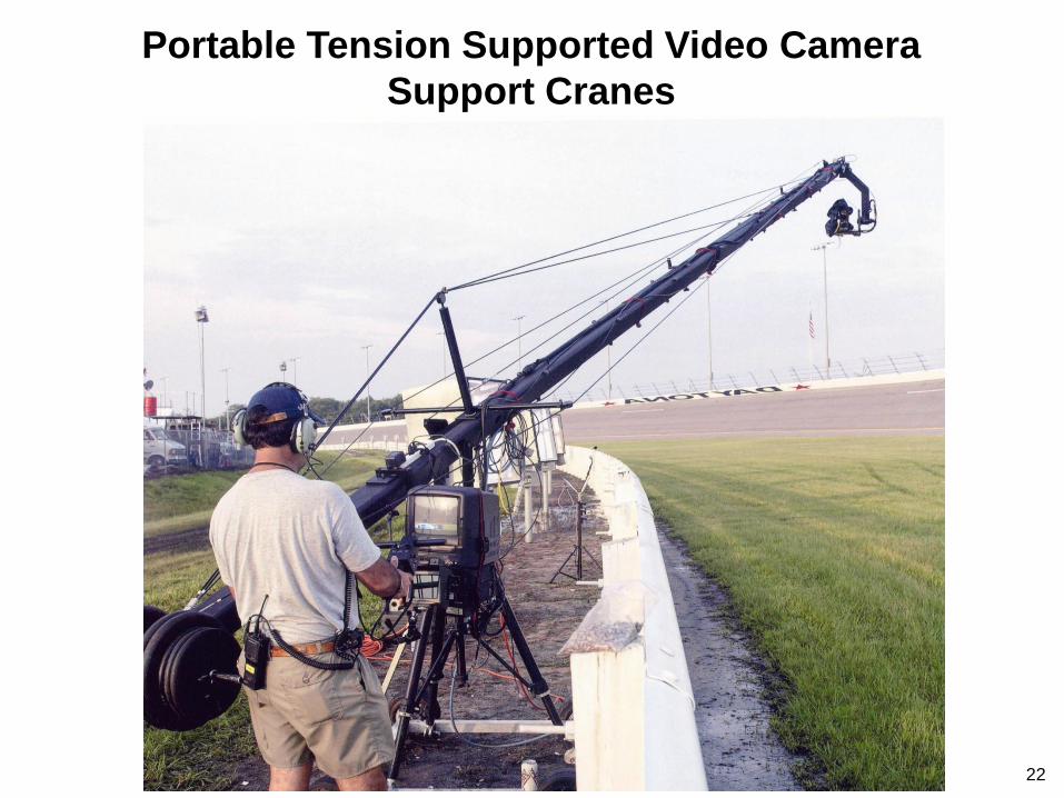
Portable Tension Supported Video Camera
Support Cranes
22

Summary of 300 kW Government Reference Array
Design Features
23
• Folded box beam members
• High-modulus composites
• No restrictions on beam wall thickness (not rolled)
• Trunk beam doubles as winglet base
• Dual blanket/single-boom winglet configuration (like ISS)
• Cable stiffening of winglets and/or trunk beam as needed
• 300 kW EOL / 450 kW BOL “easily” fits on Falcon 9
• Configurable to meet requirements
• Intended as a bellwether for very low mass and stowage
volume solar arrays
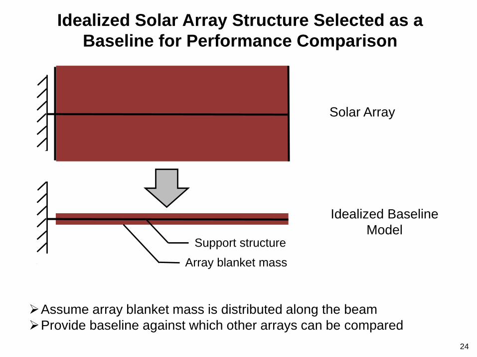
Idealized Baseline
Model
Idealized Solar Array Structure Selected as a
Baseline for Performance Comparison
Solar Array
Assume array blanket mass is distributed along the beam
Provide baseline against which other arrays can be compared
Support structure
Array blanket mass
24
25
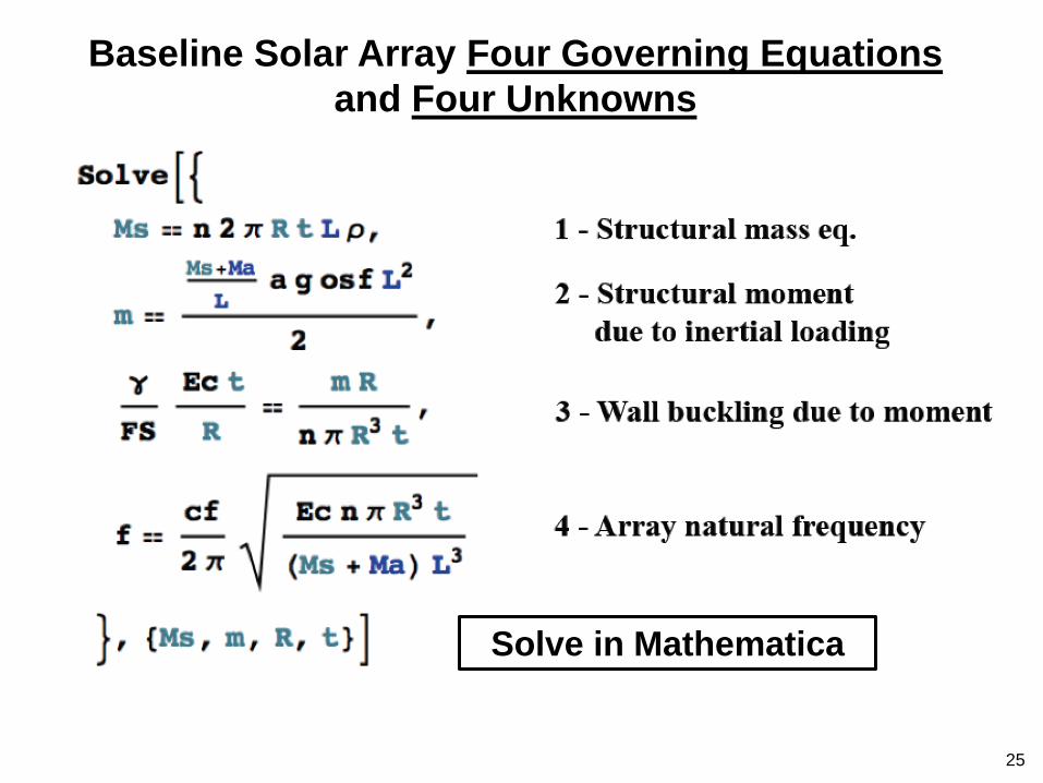
Baseline Solar Array Four Governing Equations
and Four Unknowns
Solve in Mathematica
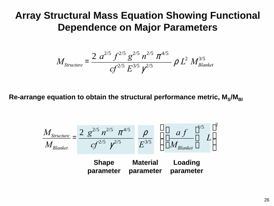
Re-arrange equation to obtain the structural performance metric, MS/MBl
26
Loading
parameter
MStructure = 2 a2/5 f 2/5 g2/5 n2/5 p 4/5
cf 2/5 E3/5 g 2/5 r L2 MBlanket
3/5
Material
parameter
Shape
parameter
MStructure
MBlanket
= 2 g2/5 n2/5 p 4/5
cf 2/5 g 2/5
r
E3/5
a f
MBlanket
æ
èç
ö
ø÷
1/5
Læ
è
çç
ö
ø
÷÷
2
Array Structural Mass Equation Showing Functional
Dependence on Major Parameters
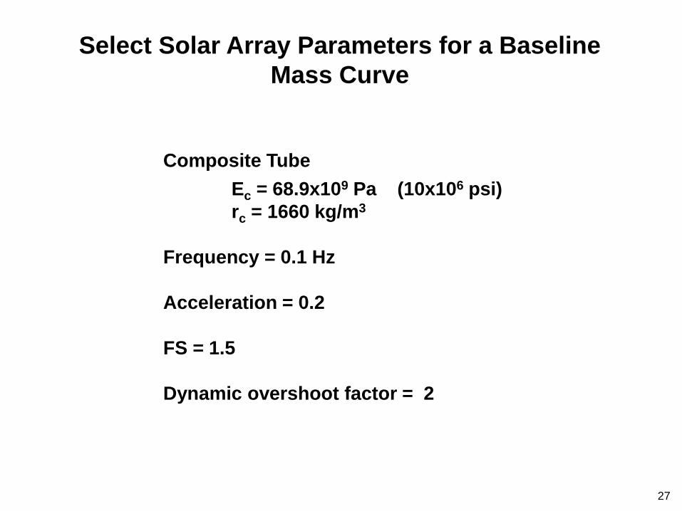
Select Solar Array Parameters for a Baseline
Mass Curve
27
Composite Tube
Ec = 68.9x10⁹ Pa (10x106 psi)
rc = 1660 kg/m3
Frequency = 0.1 Hz
Acceleration = 0.2
FS = 1.5
Dynamic overshoot factor = 2
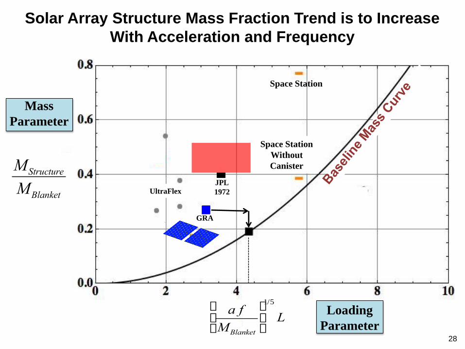
Solar Array Structure Mass Fraction Trend is to Increase
With Acceleration and Frequency
28
Space Station
Without
Canister
Spoke
Wheel
JPL
1972
Space Station
GRA
UltraFlex
a f
MBlanket
æ
èç
ö
ø÷
1/5
L
MStructure
MBlanket
Mass
Parameter
Loading
Parameter

Current Program Goal Provides Game Changing Increases
in Solar Array Power per Unit Volume
Sandwich
Array Designs
Government
Reference Array
Space
Station
Array
Dawn
PUMA
Program
Goal
29

Concluding Remarks
30
Mass performance metrics established
Array data needed for level playing field comparison:* Natural frequency
Acceleration capability
Overshoot factor used if any
Structural factor-of-safety
Blanket mass and dimensions
Array packaging volume
*It would be desirable if this data were not proprietary
300 kW government reference array developed Bellwether for structural mass fraction & packaging volume
Major effort remaining to develop and validate a viable reliable
deployment system