soils - kcmo.gov
TRANSCRIPT

1
As a customer service initiative, the Kansas City, Missouri, City Planning and Development
Department/Development Services, in cooperation with the Greater Kansas City Home Builders
Association, has developed the attached standard foundation and structural slab details for use in
all one- and two-family dwellings permitted under the 2018 International Residential Code
(IRC). These standard details will be accepted by CPD-DS for slabs and foundations meeting
the dimensions and design parameters specified herein. The standard slab details address
suspended slabs and slabs on non-engineered fill. The standard foundation wall details address
foundation walls subject to unbalanced fill conditions.
Please note that these are standard details and all customers may exercise the option of following
the prescriptive requirements of the 2018 IRC or may provide a design prepared by a licensed
professional engineer.
See the IRC for additional information. See CPD-DS Information Bulletin 100 for Requirements
for 1 & 2 Family Dwelling plan submittals
SOILS
This standard is based on undisturbed soil conditions, with assumed soil values of 2000 psf load
bearing capacity and 60 pcf (60 psf/ft) equivalent fluid pressure. Construction on fill materials
or the use of alternative soil values is acceptable where based on a site-specific geotechnical
evaluation performed by a licensed professional engineer. Other unusual site conditions may
also require geotechnical evaluation. [IRC Chapter 4]
2
CONCRETE
Concrete strength shall comply with the following minimum strength requirements at 28 days
[IRC R402.2]:
• 2,500 psi for basements floor slabs on undisturbed grade.
• 3,000 psi for footings, foundation walls, and other vertical concrete.
• 3,500 psi for carport and garage floor slabs on undisturbed grade.
• 3,500 psi for structural floor slabs.
Concrete shall be 6% (+/- 1%) air-entrained for garage slabs and for all locations footings, walls
or flatwork where exposed to weather. Rebar shall be minimum 40 ksi unless noted otherwise.
Minimum concrete cover for reinforcement (per ACI 318):
Cast against earth Exposed to weather Not exposed to weather
3” #5 or smaller 1 ½” Slabs ¾” (u.n.o.)
FOOTINGS
Exterior walls, bearing walls, columns and piers shall be supported on continuous solid masonry
or concrete footings, or other approved structural system to safely support the imposed loads and
shall be sized and reinforced in accordance with this standard or shall be engineered designed.
Footings under foundation walls shall be continuous around the structure and from one level to
the next. The continuous transitions between footings at different levels enclosing usable space
shall be made by approved solid jumps or support systems to provide safe support of the
structure. See “Typical Footing/Foundation Wall/Standard Slab at Maximum 4-foot Over-dig”
and “Footing Jump” diagrams for more detail.
The bottom of all footings shall extend not less than 36” below grade for frost protection.
Footings for freestanding accessory structures with an area of 600 square feet or less and an eave
height of 10 feet or less shall extend below grade a minimum of 12”. [IRC R403.1.4]
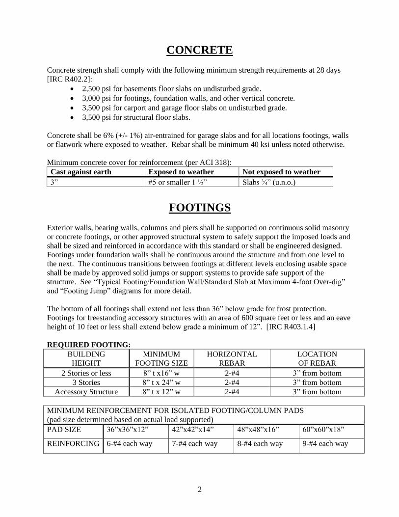
REQUIRED FOOTING:
BUILDING
HEIGHT
MINIMUM
FOOTING SIZE
HORIZONTAL
REBAR
LOCATION
OF REBAR
2 Stories or less 8” t x16” w 2-#4 3” from bottom
3 Stories 8” t x 24” w 2-#4 3” from bottom
Accessory Structure 8” t x 12” w 2-#4 3” from bottom
MINIMUM REINFORCEMENT FOR ISOLATED FOOTING/COLUMN PADS
(pad size determined based on actual load supported)
PAD SIZE 36”x36”x12” 42”x42”x14” 48”x48”x16” 60”x60”x18”
REINFORCING 6-#4 each way 7-#4 each way 8-#4 each way 9-#4 each way

3
FOOTING JUMP DETAIL:
4
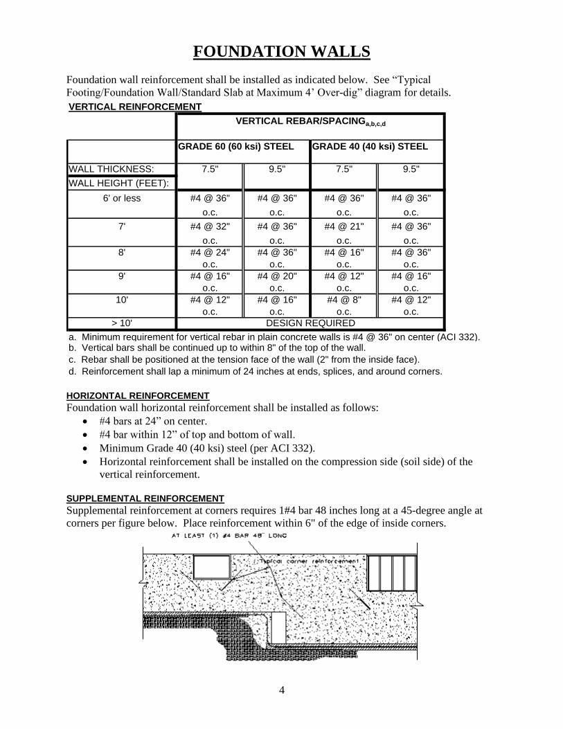
FOUNDATION WALLS
Foundation wall reinforcement shall be installed as indicated below. See “Typical
Footing/Foundation Wall/Standard Slab at Maximum 4’ Over-dig” diagram for details.
VERTICAL REINFORCEMENT
GRADE 40 (40 ksi) STEEL
WALL THICKNESS: 7.5" 9.5" 7.5" 9.5"
WALL HEIGHT (FEET):
6' or less #4 @ 36" #4 @ 36" #4 @ 36" #4 @ 36"
o.c. o.c. o.c. o.c.
7' #4 @ 32" #4 @ 36" #4 @ 21" #4 @ 36"
o.c. o.c. o.c. o.c.
8' #4 @ 24" #4 @ 36" #4 @ 16" #4 @ 36"
o.c. o.c. o.c. o.c.
9' #4 @ 16" #4 @ 20" #4 @ 12" #4 @ 16"
o.c. o.c. o.c. o.c.
10' #4 @ 12" #4 @ 16" #4 @ 8" #4 @ 12"
o.c. o.c. o.c. o.c.
> 10'
b. Vertical bars shall be continued up to within 8" of the top of the wall.
c. Rebar shall be positioned at the tension face of the wall (2" from the inside face).
d. Reinforcement shall lap a minimum of 24 inches at ends, splices, and around corners.
GRADE 60 (60 ksi) STEEL
VERTICAL REBAR/SPACINGa,b,c,d
DESIGN REQUIRED
a. Minimum requirement for vertical rebar in plain concrete walls is #4 @ 36" on center (ACI 332).
HORIZONTAL REINFORCEMENT
Foundation wall horizontal reinforcement shall be installed as follows:
• #4 bars at 24” on center.
• #4 bar within 12” of top and bottom of wall.
• Minimum Grade 40 (40 ksi) steel (per ACI 332).
• Horizontal reinforcement shall be installed on the compression side (soil side) of the
vertical reinforcement.
SUPPLEMENTAL REINFORCEMENT
Supplemental reinforcement at corners requires 1#4 bar 48 inches long at a 45-degree angle at
corners per figure below. Place reinforcement within 6" of the edge of inside corners.

5
Foundation wall not connected to floor framing at top of wall
When a wall has more than 4 feet of unbalanced backfill and is not directly attached to the floor
system at top of wall, then an engineered design is required. This design will be similar to a
retaining wall. (IRC section 404.1.1) See figures below.
This portion requires engineered design as unbalanced fill exceeds 4 feet.

6

7
DAMPPROOFING
One coat (minimum) of damp proofing or equivalent foundation membrane shall be applied to
exterior wall surfaces below grade [IRC R406.1]. Waterproofing in accordance with IRC section
406.2 is not required unless a ground water investigation indicates that excessive hydrostatic
pressure, a high-water table, or other severe soil-water conditions are known to exist.
FOUNDATION DRAINAGE
Installation of a continuous foundation drain is required where habitable or usable space for any
portion of the structure is located below grade. The foundation drain shall be at or below the
area being protected. Drainage tile shall be placed with positive or neutral slope to minimize the
accumulation of deposits in the drainage pipe. Placement of drain tile directly on top of the
footing is acceptable. [IRC R405]
See “Typical Footing/Foundation Wall/Standard Slab at Maximum 4’ Over-dig” and
“Foundation Drain Detail at Raised Slab” diagrams for details.

8
FOUNDATION ANCHORAGE
Sill plates shall be bolted to the foundation wall with a minimum ½” diameter anchor bolts
embedded at least 7 inches into the concrete. Bolts shall be spaced no greater than 6 feet on
center. There shall be a minimum of two bolts per plate section, with a bolt placed within 12
inches, and not closer than 7 bolt diameters, of the end of each plate section. The bolts shall be
located in the middle third of the width of the plate. A properly sized nut and washer shall be
tightened on each bolt to the plate. (NOTE: 7” embedment + 1 ½” sill plate + 3/4” for nut and
washer exceeds a 9” long bolt.) [IRC R403.1.6]
Please note that wall bracing methods per IRC R602 may require additional anchorage.
VAPOR RETARDER (VAPOR BARRIER)
A 6-mil polyethylene or approved vapor retarder with joints lapped a minimum of 6” is required
between the concrete floor slab and the base course or prepared subgrade. (Not required for
garage slabs or detached accessory buildings.) [IRC R506.2.3]
FOUNDATION AND LOT GRADING
Grades shall be sloped away from the foundation a minimum of 6 inches in the first 10 feet.
Alternate approaches may be approved if the alternate design is equivalent in effectiveness and
performance and provides for positive site drainage. [IRC R401.3]
9
STRUCTURAL SLABS
This section applies to concrete slabs placed on fill material which exceeds 24 inches of
compacted granulated material (sand or gravel) or 8 inches of earth. This may occur at garage
floor fills, or over excavated areas under floor slabs. The design and installation details in this
document (where applicable based on size and spacing limitations) may be used in lieu of
providing a separate design. Structural slabs exceeding the spans and conditions of the approved
details shall be designed by a Missouri registered design professional.
SLABS AT MAXIMUM 4’ OVERDIG ADJACENT TO FOUNDATION WALL
Where the soil is excavated for a maximum dimension of 4’ horizontally adjacent to a foundation
wall, the Standard Over-dig Detail may be used in lieu of a complete structural slab. See
“Typical Footing/Foundation Wall/Standard Slab at Maximum 4’ Over-dig” diagram for details.
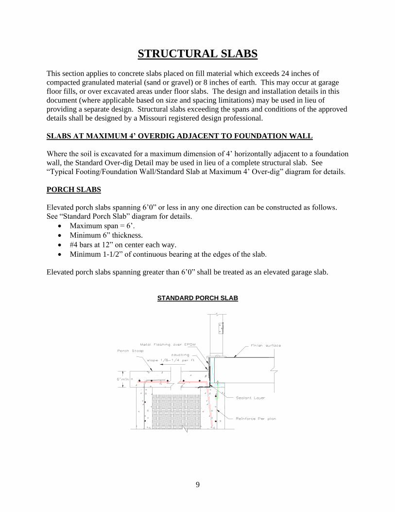
PORCH SLABS
Elevated porch slabs spanning 6’0” or less in any one direction can be constructed as follows.
See “Standard Porch Slab” diagram for details.
• Maximum span = 6’.
• Minimum 6” thickness.
• #4 bars at 12” on center each way.
• Minimum 1-1/2” of continuous bearing at the edges of the slab.
Elevated porch slabs spanning greater than 6’0” shall be treated as an elevated garage slab.
STANDARD PORCH SLAB

10

11

12

13

14

15

16

17