soils exploration report - triumphconstructionservices.com
TRANSCRIPT

Phone:
Soils Exploration
Report
Triumph Construction Services Corporation
2252 Southwind Blvd.
Bartlett, IL 60103
New Office Warehouse
480 Heartland Road
Sugar Grove, IL
Project No: 23.R000284.00001
2258 Southwind Blvd Bartlett, IL 60103
Phone: 630-503-5002
For more info: www.srntest.com

2 Project Number 23.R000284.00001 Triumph Construction Services Corporation
2258 Southwind Blvd
Bartlett, IL 60103 Phone:
630-503-5002 For more info:
www.srntest.com
TABLE OF CONTENTS
Section Page
I. TEXT
1.0 INTRODUCTION .................................................................................................................................................. 3
2.0 SITE DESCRIPTION ........................................................................................................................................... 3
3.0 PROJECT DESCRIPTION .................................................................................................................................. 3
4.0 SUBSURFACE EXPLORATION AND LABORATORY TESTING PROGRAM .......................................... 3
5.0 SUBSURFACE CONDITIONS ........................................................................................................................... 4
6.0 ANALYSIS AND RECOMMENDATIONS ......................................................................................................... 5
7.0 GENERALIZED CONSTRUCTION CONSIDERATIONS ............................................................................ 11
8.0 GENERAL LIMITATIONS ................................................................................................................................. 12
II. APPENDIX BORING LOCATION PLAN
BORING LOGS
UNIFIED CLASSIFICATION CHART
LEGEND FOR BORING LOGS
TERMS AND CONDITIONS
3 Project Number 23.R000284.00001 Triumph Construction Services Corporation
2258 Southwind Blvd
Bartlett, IL 60103 Phone:
630-503-5002 For more info:
www.srntest.com
May 6, 2020
Project No: 23.R000284.00001
Soils Exploration Report
Triumph Construction Services Corporation
New Office Warehouse 480 Heartland Road
Sugar Grove, IL
1.0 INTRODUCTION
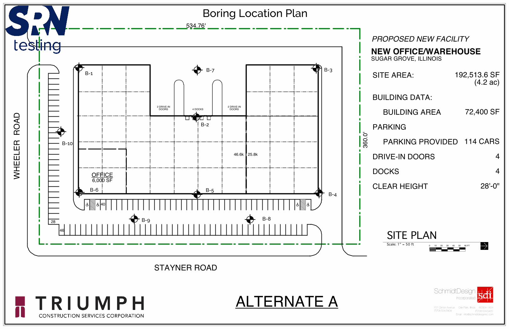
This report presents the results of a soils exploration performed for the proposed Office Warehouse facility in Sugar Grove, Illinois. These geotechnical engineering services were performed in general accordance with SRN Testing Proposal No.20-02022 dated April 7, 2020, and attached General Conditions, incorporated herein by reference. This soils exploration report presents results of the subsurface exploration and provides recommendations regarding earthwork and the design and construction of foundations, floor slabs, and pavements for the planned project. The proposed Office Warehouse facility will be located on an overall site of approximately 4.2-acres. The property is located at 480 Heartland Road in Sugar Grove, Illinois. The site slopes down from a high point of approximate Elevation 704 (Boring B-3) at its northwest corner to an approximate Elevations 699 and 698 at Borings B-6 and B-1, respectively. The site consists of a farm field with wet areas observed at the southeast corner. Boring elevations have been approximated from topography obtained from Google Earth and are estimated to be accurate to within +/- 1-foot MSL.
2.0 PROJECT DESCRIPTION
Preliminarily the proposed project will consist of a single-story slab on grade office/industrial building. Construction is expected to be precast concrete wall panels and structural steel framing supporting a metal roof deck. It will include light-duty asphaltic cement concrete parking (114 stalls), driveway pavements, and Portland cement concrete dock aprons (4 total exterior docks with drive-in doors). For this report, maximum structural loads are assumed to be 150 kips for columns, 4 kips per lineal foot for walls, and 150 psf for floor loads. The proposed building will be approximately 74,400 square feet in area. The north wall is 220 feet in length while the continuous east wall is 400 feet in length. The west wall has a centrally located indented area 160 feet by 85 feet for eight (8) proposed drive-in doors. If any of the above-assumed loadings are incorrect, then SRN Testing should be immediately notified in writing as foundation recommendations are a function of structural loading.
4.0 SUBSURFACE EXPLORATION AND LABORATORY TESTING PROGRAM
Three (3) structural soil borings, numbers B-2 through B-4, were drilled to a depth of 15 feet below existing grade. An additional three (3) structural borings, B-1, B-5, and B-6, were drilled to 10 feet below
SRN Testing Services, LLC 2258 Southwind Blvd Bartlett, IL 60103

4 Project Number 23.R000284.00001 Triumph Construction Services Corporation
2258 Southwind Blvd
Bartlett, IL 60103 Phone:
630-503-5002 For more info:
www.srntest.com
existing grade due to refusal, and four (4) parking lot borings B-7 through B-10 were drilled to 10 feet below existing grade. Their locations are shown on the Boring Location Plan in the Appendix. The boring locations were staked in the field by SRN Testing personnel. The borings were drilled with a Geoprobe 7822DT rotary rig equipped with an Automatic Drop Hammer DH103. Soil samples were obtained using a hollow stem auger and a 2-inch OD standard penetration test split spoon.
The borings were drilled, and samples tested in general accordance with currently recommended American Society for Testing and Materials specifications. The soil samples were collected and placed in sealed jars in the field to preserve moisture content and transported to Nelson Testing’s geotechnical laboratory as part of the Geotechnical Subsurface Exploration Program. Split spoon samples were taken at 2½-foot intervals to a 10 feet depth and at 5-foot intervals thereafter. Standard penetration test blow counts were obtained for all samples in blows per foot (bpf), which can be correlated with the relative density of granular soils, the presence of large boulders or concrete debris in fill soils and are an indicator for the strength of cohesive soils. Water level readings were taken during and following completion of drilling operations.
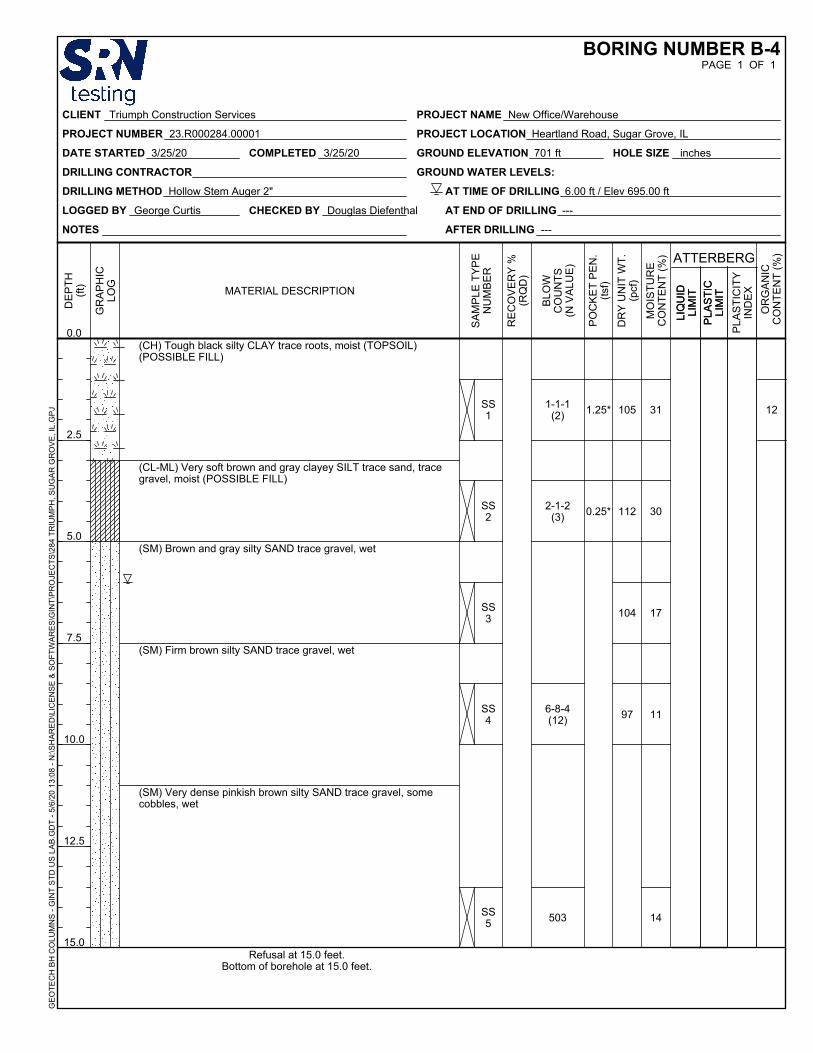
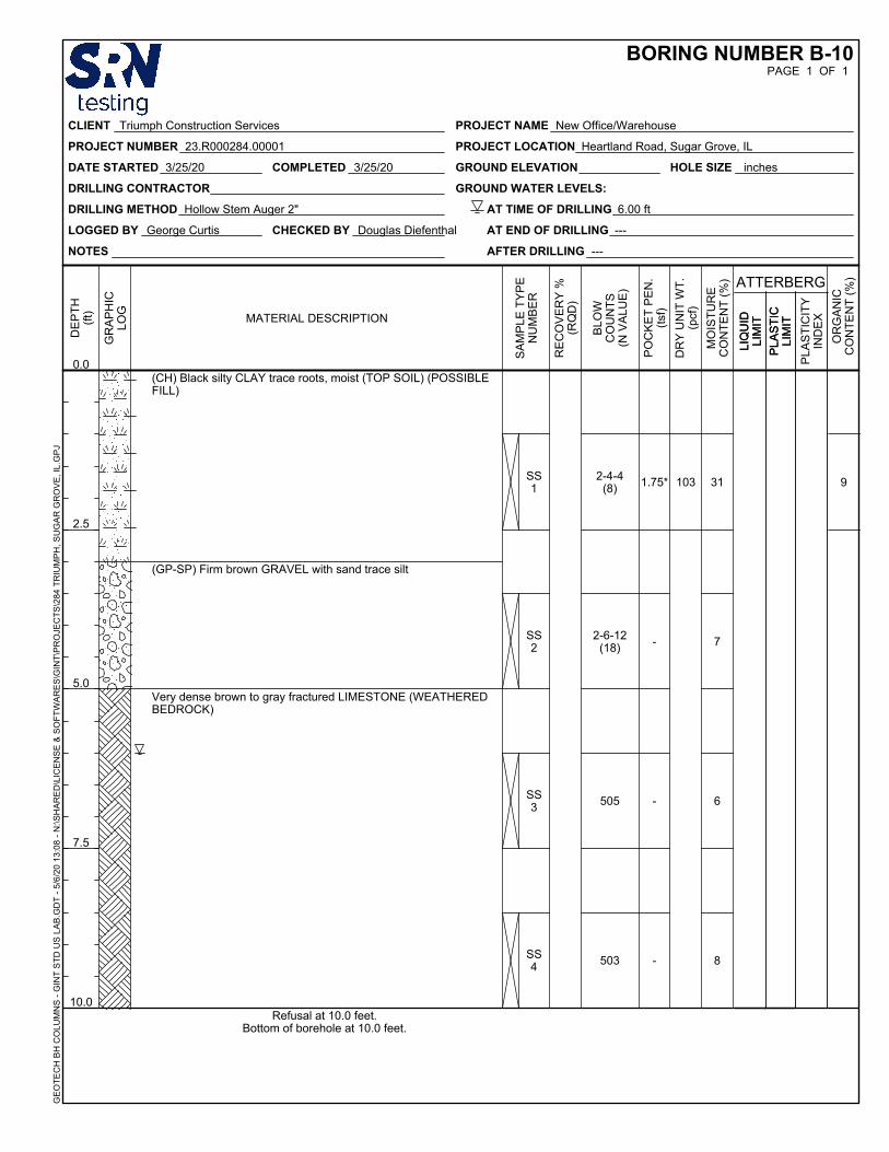
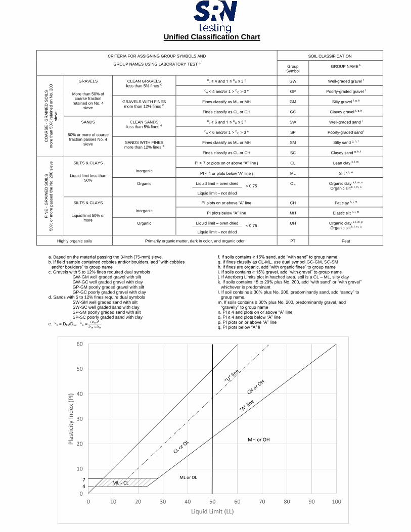
Soil samples were examined in the laboratory by an experienced soil engineer to verify field descriptions and to classify them in accordance with the Unified Soil Classification System. Laboratory testing included moisture content determinations for all cohesive and intermediate (silt or loamy) soil types. An estimate of unconfined compressive strength was obtained for all cohesive materials using a calibrated pocket penetrometer (Qp), with the strength of the samples of inorganic native clay soils presented in tons per square foot (tsf). Dry unit weight tests were run on cohesive soil specimens with these results reported in pounds per cubic foot (pcf). Natural moisture content tests were run on all samples reported in percent water weight divided by solids. A total of 9 organic content tests were performed being reported in percent organics divided by dry weight of solids. The boring logs which indicate subsurface stratigraphy and soil descriptions, results of field and laboratory tests, as well as water level observations, are enclosed in the appendix. Strata changes are indicated by a definite line on the boring logs. However, the actual change in the soil type may be more gradual. Where changes occur between soil samples, the location of the change must necessarily be estimated using all available information and may not be shown at the exact actual depth.
5.0 SUBSURFACE CONDITIONS
5.1 Soil Conditions Topsoil, possible fill soils were encountered in all borings to a depth of approximately 2 to 3 feet below existing grade. They consisted mostly of black silty clay with trace roots and organics. The organic content of these soils ranged from 3 to 12 percent by weight. The majority being greater than 10 percent organic content. These possible fill soils had moisture contents ranging from 11 to 48 percent. Their consistency ranged from soft to tough or 0.25 to 2.0 tons per square foot (tsf) with dry unit weights ranging from 98 to 131 pounds per cubic foot (pcf). Their organic content averaged greater than 9 percent by weight. These parameters indicate the possible fill is variable, not having been placed to meet a compaction specification, and is considered unsuitable for use as engineered fill or as foundation bearing soils.

5 Project Number 23.R000284.00001 Triumph Construction Services Corporation
2258 Southwind Blvd
Bartlett, IL 60103 Phone:
630-503-5002 For more info:
www.srntest.com
Beneath the topsoil possible fill stratum, granular very loose to firm clayey sand, fine to coarse sand, and gravel soils were encountered extending from three to eight feet below existing grade in Borings B-1, B-2, B-5, B-7, and B-10. Their Standard Penetration test results ranged from 4 to 19 blow per foot (bpf). Native soft to tough silty clay and clayey silt soils were encountered beneath the topsoil possible fill stratum in Borings B-3, B-4, B-6. B-8 and B-9 extending 3 to 6 feet below existing grade. The unconfined compressive strength of these soils ranged from 0.25 to 2 tons per square foot (tsf) with dry unit weight ranging from 95 to 112 pounds per cubic foot (pcf). Beneath the above-described soils firm to very dense silty sands and fractured weathered limestone and sandstone bedrock was encountered to boring termination in all borings. An exception was encountered in boring B-3 where loose silty sand extended 6 to 10 feet below existing grade, which then terminated in very dense silty sand. The standard penetration blow count in these soils ranged from 11 to greater than of 42 bpf with the exception in boring B-3 where they are ranging from 6 to 9 bpf in its loose zone.
5.2 Groundwater Conditions The borings were observed during and after completion of drilling for the presence and level of free water. At the time of drilling, a free water level was observed in all boreholes at 8 feet below existing grade apart from boring B-2 in which it was not noted. Water levels may fluctuate due to seasonal variations in the amount of rainfall, runoff, transpiration, and other factors not evident at the time the borings were performed. Water levels may exist in the clay fill soils as a perched condition where the clay soils act to hold up water levels due to their impermeability.
6.0 ANALYSIS AND RECOMMENDATIONS
6.1 Building Foundations In our opinion, the topsoil possible fill materials were not placed as an engineered fill in a controlled manner as per a compaction specification such as 95% ASTM D-1557, and in general, they are not considered suitable for foundation support. Additionally, their organic content indicates they are not suitable for use as an engineered fill beneath building foundations, and in cases where their organic content equals or exceeds ten percent is considered unsuitable for support of pavement areas. We recommend the topsoil possible fill soils be removal and replacement with suitable recommended soils as needed during site grading operations. Fill soils should be capable of passing a proof roll test under the supervision of a representative of the geotechnical engineer. They should be compacted to meet 95% of modified proctor specifications per ASTM D-1557. Fill lifts should not exceed 9 inches for cohesive backfill and 12 inches for granular backfill.
On the basis of the soil boring logs and the laboratory testing of the soil samples, we recommend that the proposed structure be supported by continuous and isolated shallow spread footings designed for a net allowable bearing capacity of 3000 psf as described in Table 1 below. Net allowable soil bearing pressure is the pressure transmitted to the foundation soils in excess of the surrounding overburden pressure at the level of the foundation. For frost considerations, all exterior footings should be constructed at least 3.5 feet below outside finished grade and 4.0 feet for foundations located outside of heated building limits. Interior footings may be constructed at higher elevations if they are protected against frost heave in the event of winter construction. All perimeter shallow spread foundation footings should be reinforced with a minimum two #5 rebars top and bottom. Shallow spread footing widths

6 Project Number 23.R000284.00001 Triumph Construction Services Corporation
2258 Southwind Blvd
Bartlett, IL 60103 Phone:
630-503-5002 For more info:
www.srntest.com
should be a minimum of 2 feet for continuous footings and 3 feet square for isolated footings regardless of calculated width and area. Table 1 lists boring numbers with recommended undercut depth and recommended replacement with Illinois Department of Transportation CA-1 or CA-3 stone topped with compacted CA-6. This stone should be placed and tamp compacted with a backhoe bucket. The last few feet of replaced fill should be CA-6 compacted to meet a 95% of Modified proctor ASTM D-1557 compaction specification.
TABLE 1
Boring Number
Recommended Undercut in Feet to reach 3000 psf
net allowable bearing
Recommended Bearing Soil
Recommended backfill with CA-1/CA-3 and upper two feet of CA-6 compacted to reach
95% of ASTM D-1557 compaction
B-1 3.0 Firm fine to coarse SAND None
B-2 5 to 8.5 Very Tough Silty CLAY Backfill as needed
B-3 6 to 8.5
Dense silty SAND after drawing down water table 2
feet below the proposed bearing elevation
Backfill as needed
B-4 5 to 8.5
Firm silty SAND after drawing down water table 2
feet below the proposed bearing elevation
Backfill as needed
B-5 6.0 Firm to very dense
fractured LIMESTONE Backfill as needed
B-6 3.0 Firm clayey SAND None
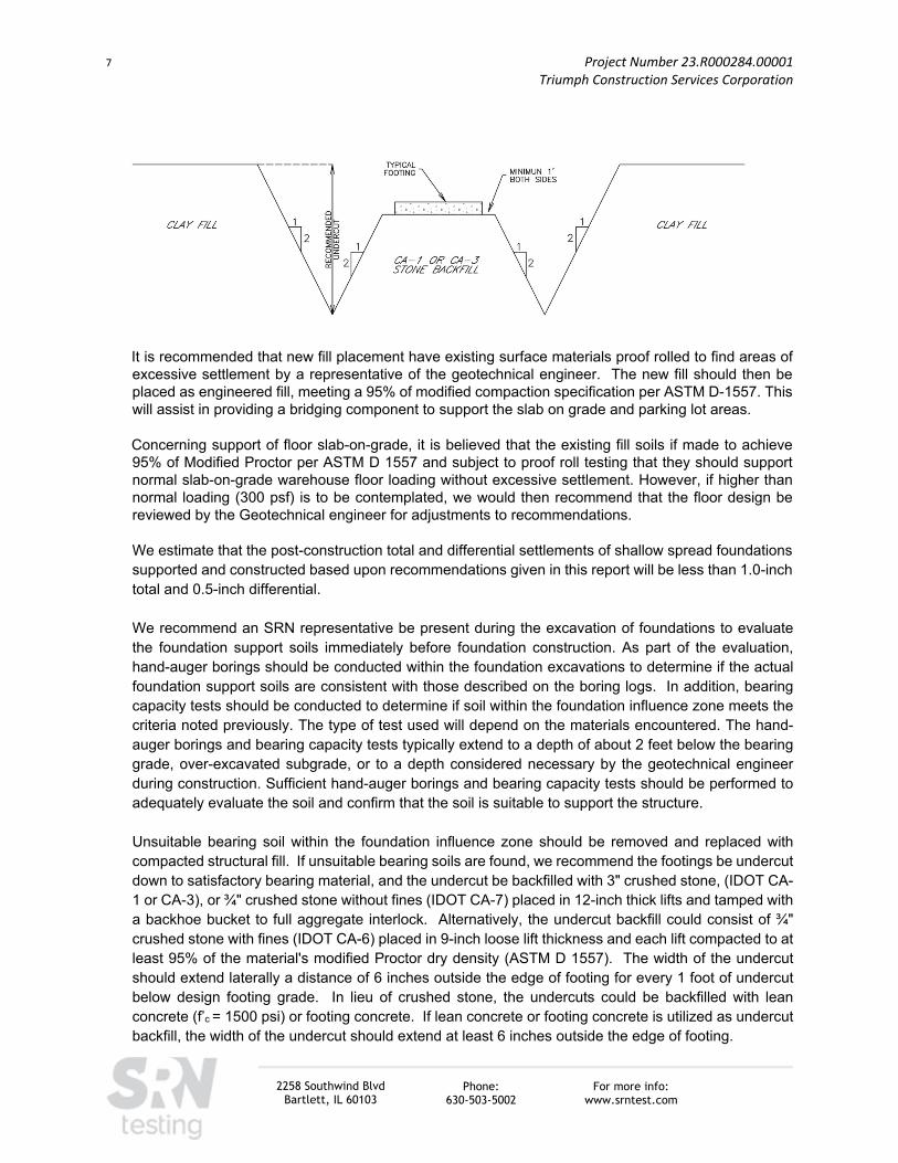
Generally, fill soils are considered unsuitable for support of foundations if they have not been engineered. Such fill soils without confirmation of meeting a compaction specification of 95% of Modified Proctor cannot be assumed to be suitable for support of building foundations. Cohesive fill soils should be selected with liquid limits equal or less than 40%, and plasticity limits less than 20% as directed by the geotechnical engineer’s representative to prevent the placement of highly plastic soils. All undercuts should be increased at their base to achieve foundation support of stone by a slope of 1 horizontal to 2 vertical, and the excavation sides be brought up to grade achieving a similar slope in existing fill, see the diagram 1 below.
7 Project Number 23.R000284.00001 Triumph Construction Services Corporation
2258 Southwind Blvd
Bartlett, IL 60103 Phone:
630-503-5002 For more info:
www.srntest.com
It is recommended that new fill placement have existing surface materials proof rolled to find areas of excessive settlement by a representative of the geotechnical engineer. The new fill should then be placed as engineered fill, meeting a 95% of modified compaction specification per ASTM D-1557. This will assist in providing a bridging component to support the slab on grade and parking lot areas.
Concerning support of floor slab-on-grade, it is believed that the existing fill soils if made to achieve 95% of Modified Proctor per ASTM D 1557 and subject to proof roll testing that they should support normal slab-on-grade warehouse floor loading without excessive settlement. However, if higher than normal loading (300 psf) is to be contemplated, we would then recommend that the floor design be reviewed by the Geotechnical engineer for adjustments to recommendations.
We estimate that the post-construction total and differential settlements of shallow spread foundations supported and constructed based upon recommendations given in this report will be less than 1.0-inch total and 0.5-inch differential. We recommend an SRN representative be present during the excavation of foundations to evaluate the foundation support soils immediately before foundation construction. As part of the evaluation, hand-auger borings should be conducted within the foundation excavations to determine if the actual foundation support soils are consistent with those described on the boring logs. In addition, bearing capacity tests should be conducted to determine if soil within the foundation influence zone meets the criteria noted previously. The type of test used will depend on the materials encountered. The hand-auger borings and bearing capacity tests typically extend to a depth of about 2 feet below the bearing grade, over-excavated subgrade, or to a depth considered necessary by the geotechnical engineer during construction. Sufficient hand-auger borings and bearing capacity tests should be performed to adequately evaluate the soil and confirm that the soil is suitable to support the structure.
Unsuitable bearing soil within the foundation influence zone should be removed and replaced with compacted structural fill. If unsuitable bearing soils are found, we recommend the footings be undercut down to satisfactory bearing material, and the undercut be backfilled with 3" crushed stone, (IDOT CA-1 or CA-3), or ¾" crushed stone without fines (IDOT CA-7) placed in 12-inch thick lifts and tamped with a backhoe bucket to full aggregate interlock. Alternatively, the undercut backfill could consist of ¾" crushed stone with fines (IDOT CA-6) placed in 9-inch loose lift thickness and each lift compacted to at least 95% of the material's modified Proctor dry density (ASTM D 1557). The width of the undercut should extend laterally a distance of 6 inches outside the edge of footing for every 1 foot of undercut below design footing grade. In lieu of crushed stone, the undercuts could be backfilled with lean concrete (f’c = 1500 psi) or footing concrete. If lean concrete or footing concrete is utilized as undercut backfill, the width of the undercut should extend at least 6 inches outside the edge of footing.

8 Project Number 23.R000284.00001 Triumph Construction Services Corporation
2258 Southwind Blvd
Bartlett, IL 60103 Phone:
630-503-5002 For more info:
www.srntest.com
6.2 Concrete Floor Slab Design and Construction The floor slab for the office/industrial building can be supported at grade on the planned fill provided this soil is placed to meet a 95% of modified compaction specification per ASTM D1557. Existing native cohesive and granular soils or engineered fill provided these soils are prepared as recommended in the report and appear firm under proof rolling, as discussed below. A coefficient of subgrade reaction (k) of 150 pounds per cubic inch (pci) is recommended for typical warehouse concrete floor slab design with normal loading of 300 psf or less. However, where higher loads such as may be encountered by loading from steel coils or heavy racking system leg loads (i.e., floor loads greater than 300 psf and/or rack loads exceeding 10 kips) a lower coefficient of subgrade reaction (k) of 100 pounds per cubic inch (pci) is recommended. It is recommended that a minimum 6-inch thick granular base be utilized directly below the slab to provide uniform support. Typical base course materials should consist of IDOT CA-6 and compacted to meet 95% of Modified Proctor per ASTM D 1557. Alternatively, IDOT CA-7 could be considered for use as an aggregate base providing more effective capillary break though susceptible to "shoving" and should be compacted to a firm, stable condition under proof rolling or compacted to full aggregate interlock. The use of a vapor retarder or barrier should be considered beneath concrete slabs on grade that will be covered with wood, tile, carpet, or other moisture sensitive or impervious coverings, or when the slab will support equipment sensitive to moisture. When conditions warrant the use of a vapor retarder/barrier, the slab designer and slab contractor should refer to ACI 302 and ACI 306 for procedures and cautions regarding the use and placement of a vapor retarder/barrier. Additionally, the manufacturer of floor covering specifications should overrule all the above and be followed for use with respect to vapor retarder/barrier. All concrete slabs should be isolated from foundation elements, i.e., jointed around columns and foundation walls, to permit settlement to occur without causing undue cracking or distress resulting from concrete shrinkage and minor differential settlement. It is recommended that slab-on-grade construction and jointing should be in accordance with ACI 360-10 (Guide to Design of Slabs-on-Ground).
6.3 Site Grading Based on the visual examination of recovered soil samples, the existing cohesive fill soils encountered in the borings would likely meet the criteria for use as engineered fill material. Engineered fill should consist of approved materials that are free of organic matter and debris. Granular materials should have between 5 and 15% passing the No. 200 sieve. Frozen material should not be used, and fill should not be placed on a frozen subgrade. Cohesive (clay) soils used as fill for this project should have liquid limit less than 40 and a plasticity index less than 20; cohesive soils that do not meet these criteria should be considered "unsuitable." As part of final grading, building and areas to be paved should be cleared of any vegetation, surficial topsoil fill, and any organic materials. The building and pavement areas should then be proof rolled to detect the presence of unsuitable or unstable soil types in the upper subgrade. The proof-roll should be conducted by the geotechnical engineer's representative using an approved piece of heavy construction equipment. All soft or unstable materials determined by proof-rolling should be reworked,

9 Project Number 23.R000284.00001 Triumph Construction Services Corporation
2258 Southwind Blvd
Bartlett, IL 60103 Phone:
630-503-5002 For more info:
www.srntest.com
recompacted, or if that does not substantially improve subgrade stability, removed, and replaced with approved engineered fill. It is recommended that all engineered fill materials be compacted to meet at least 95% of the material’s modified Proctor dry density (ASTM D 1557). All fill soils should be placed in loose lift thicknesses no greater than 9 inches. Moisture control is important in achieving the required degree of compaction for engineered fill soils. It is recommended that the moisture content of engineered fill within 1% below and 3% above the optimum moisture as established by its laboratory compaction curve. If the soil is compacted too dry, it will have an apparent stability that will be lost if it later becomes saturated. If the soil is too wet, the Contractor will not be able to achieve proper compaction. Engineered fill that does not meet the density and water content requirements is recommended to be replaced or scarified to a sufficient depth (likely 6 to 12 inches, or more), moisture-conditioned, and compacted to the required density. A subsequent lift of fill should only be placed after it is confirmed that the previous lift was properly placed and compacted. Sub-grade soil may need to be re-compacted immediately before construction because equipment traffic and adverse weather may reduce soil stability.
6.4 Lateral Earth Pressures Earth pressures for below-grade walls such, as the planned depressed docks, are a function of the type of backfill used, groundwater conditions, and the design structural boundary retaining conditions. These earth pressures are typically given as Equivalent Fluid Pressures (EFP) for the soils. Table 2 given below may be used for cohesive and granular backfills assuming active (Ka), at-rest (Ko), and (Kp) passive earth pressures. The values shown represent the increase in lateral pressure for 1.0-foot depth distance measured in pounds per square foot (psf/ft).
TABLE 2
EQUIVALENT FLUID PRESSURE (PSF/FT) BACKFILL TYPE DRAINED CONDITION UNDRAINED CONDITION
ACTIVE STATE
Granular 35 80 Cohesive 50 90
AT-REST STATE
Granular 50 90 Cohesive 65 100
PASSIVE STATE
Granular 400 250 Cohesive 350 250
The active condition applies to retaining walls which are free to rotate at their top. At-rest pressures should be used for retaining walls which are fixed at their top and bottom or otherwise restrained from moving. Passive earth pressures are resultant pressure provided by backfill being pushed against.
10 Project Number 23.R000284.00001 Triumph Construction Services Corporation
2258 Southwind Blvd
Bartlett, IL 60103 Phone:
630-503-5002 For more info:
www.srntest.com
The values shown above are nominal, i.e., are based on average soil conditions. They also do not reflect any backfill above the level horizontal height behind walls, i.e., up-sloping backfill will increase lateral earth pressures and should be analyzed for by slope stability analyses. It should be noted that for the EFP values given for granular soils be valid, the wedge of granular materials should extend a minimum distance at the top of the wall (or ground surface) equal to the height of the wall. Appropriate surcharge loads should be included in the design of retaining/below-grade walls for any adjacent pavements, sidewalks, floor slabs, and foundations lying within a 1H:1V zone from the base of the below-grade floor slab to the ground surface. Surcharge loads of 100 and 200 psf are normally used for sidewalks and pavements, respectively. Backfill placed within 2 feet behind below-grade walls should consist of a clean, free-draining granular soil containing less than 5% by weight passing the No. 200 sieve. To calculate the resistance against sliding, a value of 0.45 should be used as the ultimate coefficient of friction between the footing and the underlying soil. The granular backfill should be separated from cohesive soil (native or backfill) with a high survivability geotextile having an apparent opening size (AOS) of 70 to 100 to prevent migration of fines into the granular backfill. Backfill placed against below-grade walls should be compacted to 90 percent of Modified Proctor density per ASTM D 1557. Compaction in excess of 90 to 95 percent may result in greater lateral earth pressures than recommended for design. Additionally, heavy compaction equipment should be kept away from retaining walls, as this may result in over-stressing of the wall and excessive movement.
6.5 Pavement Design and Construction It is recommended that an Illinois Bearing Ratio (IBR) value of 3.0 be used for the design of asphaltic cement concrete pavements. A coefficient of subgrade reaction (k) of 150 pci may be used for the design of Portland cement concrete pavements. The use of these values assumes that any soft or unstable subgrade areas will be remediated through proof-roll testing. Pavement subgrade preparation should include removing of existing vegetation, surficial topsoil/root zone materials, and/or cutting to proposed subgrade level; the exposed subgrade should be recompacted, and then proof rolled. Proof rolling should be performed to detect the presence of unsuitable or unstable soil in the upper subgrade and should be performed using a loaded tandem-axle truck. Soft or unstable areas determined by proof-rolling (areas which are noted to rut ½ inch or more), should be remediated by removal and replacement methods with granular materials compacted to meet 95% of Modified Proctor per ASTM D 1557 or moisture reconditioning, recompaction and retesting. If proof roll tests do not pass, then undercutting the unstable soils to typical depths of 1 to 2 feet below final subgrade elevation and replacement with coarse granular material such as IDOT gradation CA-1 or CA-7 should be employed. A geotextile separation/reinforcement fabric or geogrid product may be placed at the bottom of the undercuts prior to backfilling with the coarse granular material. Additionally, subgrade stabilization may be accomplished using lime stabilizing products, fly ash, or cement-based pozzolanic materials mixed with the soils at 5% by weight. In general, it is recommended a lime specialty contractor be employed for such operations. Base course and subbase materials should otherwise conform to IDOT gradation CA-6 and be compacted to 95 percent Modified Proctor density per ASTM D 1557 or 100 percent of the Standard Proctor per ASTM D 698 maximum density value.

11 Project Number 23.R000284.00001 Triumph Construction Services Corporation
2258 Southwind Blvd
Bartlett, IL 60103 Phone:
630-503-5002 For more info:
www.srntest.com
Flexible asphalt materials should be an approved IDOT Superpave minimum design, with N50 typical for light-duty parking lots and N70 for heavy-duty pavements. IDOT Standard Specifications for Road and Bridge Construction, Sections 406, and 1032 should also be referenced. They should be compacted to between 93 and 97 percent of their theoretical maximum density, as determined by the supplier Big D value. Portland cement concrete pavements are recommended for areas subject to repeated truck traffic, truck turning areas, and trash compactor/dumpster pads. Garbage truck dumpster loading areas should be designed using (PCC) heavy-duty concrete pavement. 6.6 Seismic Site Design In general accordance with Table 20.3-1 of the ASCE 7-10 Standard as referenced in the 2012 International Building Code (IBC), a Seismic Site Class D is recommended for seismic design. The 2012 IBC requires a site soil profile determination extending to a depth of 100 feet for seismic site classification. The maximum depth explored during our soil exploration was about 15 feet. We have assumed that the soil conditions beyond the depths explored is like or better than the soil conditions in the upper 15 feet. Thus, based on this section of the IBC and the conditions encountered at the boring locations, Site Class D can be used for design of the proposed project. 6.7 Groundwater Dewatering In general, free groundwater was encountered at 6 feet below existing grade. Table 1 recommends some undercuts below this depth, and therefore dewatering of subgrade will be required before excavating to below these depths. It is expected that a sump and pump system should be able to keep ahead of dewatering requirements. It should be noted that attempted excavation of silty sands below a free groundwater table will cause them to liquify (turn quick) unless the water table is brought down to at least two feet below planned excavation depth. It is recommended that a groundwater specialist review the boring logs and give an opinion as to the need for a groundwater removal system other than a trench with a sump and pump system. SRN Testing could install monitoring wells if they were to be required to provide additional data for this review. Saturated silty sands on the site at depth may begin to cause pumping due to heavy construction equipment and may affect dewatering requirements.
7.0 GENERALIZED CONSTRUCTION CONSIDERATIONS
7.1 Adverse Weather Site soil is moisture sensitive and will become unstable when exposed to adverse weather such as rain, snow, and freezing temperatures. Therefore, it might be necessary to remove or stabilize the upper 6 to 12 inches (or more) of soil due to adverse weather, which commonly occurs during late fall, winter, and early spring. Additional over-excavation and/or stabilization of unstable soil should be expected if construction is during or after adverse weather. Some over-excavation or subgrade stabilization may be necessary even if construction is during and after favorable, dry weather. Because site preparation is weather dependent, bids for site preparation, and other earthwork activities, are recommended to be based on the time of year that construction will be conducted.
To protect soil from adverse weather, the site surface is recommended to be smoothly graded and contoured during construction to divert surface water away from construction areas. Also, contoured subgrades are recommended to be rolled with a smooth-drum compactor, before precipitation, to “seal” the surface. Furthermore, construction traffic should be restricted to certain aggregate-covered areas to minimize traffic-related soil disturbance.

12 Project Number 23.R000284.00001 Triumph Construction Services Corporation
2258 Southwind Blvd Bartlett, IL 60103
Phone: 630-503-5002
For more info: www.srntest.com
7.2 Environmental Concerns Evaluation of the suitability of site soils for reuse with respect to environmental considerations is beyond SRN Testing scope of services addressed in this report. Dependent on the environmental conditions, soils encountered during construction activities may require proper placement on-site or disposal off-site as a special waste to an IEPA approved facility.
7.3 Recommended Construction Material Testing This report was prepared assuming that SRN Testing will perform Construction Materials Testing ("CMT") services during construction of the proposed development. In general, CMT services are recommended (and expected) to at least include observation and testing of foundation and slab support soil, concrete, and other construction materials. It might be necessary for SRN Testing to provide supplemental geotechnical recommendations based on the results of CMT services and specific details of the project not known at this time.
8.0 GENERAL LIMITATIONS
This report is strictly based on the project description given earlier in this report. SRN Testing must be notified if any parts of the project description or our assumptions are not accurate so that this report can be amended if needed. This report assumes that the site construction will be designed and constructed according to the codes that govern construction at the site. The conclusions and recommendations in this report are based on estimated subsurface conditions, as shown on the boring logs.
SRN Testing must be notified if the subsurface conditions that are encountered during construction of the proposed development differ from those shown on these Logs because this report will likely need to be revised. General comments and limitations of this report are given in the appendix. Please call if there are any questions or if we may be of further service.
Respectfully,
SRN TESTING SERVICES
Scott R. Nelson Douglas C. Diefenthal President Senior Geotechnical Engineer
Registered Professional Engineer Illinois No. 062-037189
534.76'
360.
0'
STAYNER ROAD
WHE
ELER
RO
AD
28
46
40
46.6k 25.8k
2 DRIVE-INDOORS 4 DOCKS
2 DRIVE-INDOORS
OFFICE6,000 SF
SITE PLANScale: 1" = 50 ft 0 10 20 30 40 50 60 FT
707 Clinton Avenue Oak Park, Illinois 60304-1404
Incorporated SchmidtDesign
(T)708.524.5404 (F)708.524.5420Email : [email protected]
NEW OFFICE/WAREHOUSESUGAR GROVE, ILLINOIS
PROPOSED NEW FACILITY
SITE AREA:
BUILDING DATA:
BUILDING AREA
PARKING
PARKING PROVIDED
DRIVE-IN DOORS
DOCKS
CLEAR HEIGHT
192,513.6 SF(4.2 ac)
72,400 SF
114 CARS
4
4
28'-0"
ALTERNATE A
B-1
B-2
B-3
B-4B-5B-6
B-7
B-8B-9
B-10
Boring Location Plan

SS1
SS2
SS3
SS4
2-4-3(7)
4-8-11(19)
6-33-25(58)
9-503
105 40
8
10
8
(CH) Black silty CLAY trace roots, moist (TOPSOIL) (POSSIBLEFILL)
(SP-SM) FIrm brown fine to coarse SAND with gravel trace silt,moist
(GC) Very dense gray clayey GRAVEL with silt and sand(WEATHERED BEDROCK)
(GM) Very dense brown silty GRAVEL with sand (WEATHEREDBEDROCK)
Refusal at 10.0 feet.Bottom of borehole at 10.0 feet.
NOTES
GROUND ELEVATION 699 ft
LOGGED BY George Curtis
DRILLING METHOD Hollow Stem Auger 2"
DRILLING CONTRACTOR GROUND WATER LEVELS:
CHECKED BY Douglas Diefenthal
DATE STARTED 3/25/20 COMPLETED 3/25/20
AT TIME OF DRILLING 6.00 ft / Elev 693.00 ft
AT END OF DRILLING ---
AFTER DRILLING ---
HOLE SIZE inches
SA
MP
LE
TY
PE
NU
MB
ER
RE
CO
VE
RY
%(R
QD
)
BL
OW
CO
UN
TS
(N V
AL
UE
)
DR
Y U
NIT
WT
.(p
cf)
MO
IST
UR
EC
ON
TE
NT
(%
)
PL
AS
TIC
LIM
IT
OR
GAN
IC
CO
NT
EN
T (%
)
GR
AP
HIC
LO
G
DE
PT
H(f
t)
0.0
2.5
5.0
7.5
10.0
MATERIAL DESCRIPTION
PO
CK
ET
PE
N.
(tsf
)
PL
AS
TIC
ITY
IND
EX
PL
AS
TIC
LIM
IT
LIQ
UID
LIM
ITLI
QU
IDLI
MIT
ATTERBERG
PAGE 1 OF 1BORING NUMBER B-1
CLIENT Triumph Construction Services
PROJECT NUMBER 23.R000284.00001
PROJECT NAME New Office/Warehouse
PROJECT LOCATION Heartland Road, Sugar Grove, IL
GE
OT
EC
H B
H C
OL
UM
NS
- G
INT
ST
D U
S L
AB
.GD
T -
5/6
/20
13
:08
- N
:\S
HA
RE
D\L
ICE
NS
E &
SO
FT
WA
RE
S\G
INT
\PR
OJE
CT
S\2
84
TR
IUM
PH
, S
UG
AR
GR
OV
E,
IL.G
PJ
10

SS1
SS2
SS3
SS4
SS5
1-1-1(2)
1-1-7(8)
504
104
98
27
23
27
37
10
(CL) Very soft black silty CLAY trace roots, moist (TOPSOIL)(POSSIBLE FILL)
(SC) Loose dark brown clayey SAND trace silt, trace gravel
(CL) Very tough reddish brown silty CLAY trace sand, trace gravel
Very dense gray fractured LIMESTONE (BEDROCK)
Bottom of borehole at 15.0 feet.
3.25*
NOTES
GROUND ELEVATION 700 ft
LOGGED BY George Curtis
DRILLING METHOD Hollow Stem Auger 2"
DRILLING CONTRACTOR GROUND WATER LEVELS:
CHECKED BY Douglas Diefenthal
DATE STARTED 3/25/20 COMPLETED 3/25/20
AT TIME OF DRILLING ---
AT END OF DRILLING ---
AFTER DRILLING ---
HOLE SIZE inches
SA
MP
LE
TY
PE
NU
MB
ER
RE
CO
VE
RY
%(R
QD
)
BL
OW
CO
UN
TS
(N V
AL
UE
)
DR
Y U
NIT
WT
.(p
cf)
MO
IST
UR
EC
ON
TE
NT
(%
)
PL
AS
TIC
LIM
IT
OR
GAN
IC
CO
NTE
NT
(%)
GR
AP
HIC
LO
G
DE
PT
H(f
t)
0.0
2.5
5.0
7.5
10.0
12.5
15.0
MATERIAL DESCRIPTION
PO
CK
ET
PE
N.
(tsf
)
PL
AS
TIC
ITY
IND
EX
PL
AS
TIC
LIM
IT
LIQ
UID
LIM
ITLI
QU
IDLI
MIT
ATTERBERG
PAGE 1 OF 1BORING NUMBER B-2
CLIENT Triumph Construction Services
PROJECT NUMBER 23.R000284.00001
PROJECT NAME New Office/Warehouse
PROJECT LOCATION Heartland Road, Sugar Grove, IL
GE
OT
EC
H B
H C
OL
UM
NS
- G
INT
ST
D U
S L
AB
.GD
T -
5/6
/20
13
:08
- N
:\S
HA
RE
D\L
ICE
NS
E &
SO
FT
WA
RE
S\G
INT
\PR
OJE
CT
S\2
84
TR
IUM
PH
, S
UG
AR
GR
OV
E,
IL.G
PJ 10

SS1
SS2
SS3
SS4
SS5
1-1-1(2)
2-1-2(3)
3-3-3(6)
3-4-5(9)
503
112
95
101
97
48
31
25
20
19
(CH) Very soft black silty CLAY trace roots, wet (TOPSOIL)(POSSIBLE FILL)
(CL-ML) Very soft brown and gray clayey SILT trace sand, tracegravel, wet
(SM) Loose brown and gray silty SAND trace gravel, wet
(SM) Loose to very dense brown silty SAND trace gravel, wet
Bottom of borehole at 15.0 feet.
0.25*
NOTES
GROUND ELEVATION 704 ft
LOGGED BY George Curtis
DRILLING METHOD Hollow Stem Auger 2"
DRILLING CONTRACTOR GROUND WATER LEVELS:
CHECKED BY Douglas Diefenthal
DATE STARTED 3/25/20 COMPLETED 3/25/20
AT TIME OF DRILLING 6.00 ft / Elev 698.00 ft
AT END OF DRILLING ---
AFTER DRILLING ---
HOLE SIZE inches
SA
MP
LE
TY
PE
NU
MB
ER
RE
CO
VE
RY
%(R
QD
)
BL
OW
CO
UN
TS
(N V
AL
UE
)
DR
Y U
NIT
WT
.(p
cf)
MO
IST
UR
EC
ON
TE
NT
(%
)
PL
AS
TIC
LIM
IT
OR
GAN
IC
CO
NTE
NT
(%)
GR
AP
HIC
LO
G
DE
PT
H(f
t)
0.0
2.5
5.0
7.5
10.0
12.5
15.0
MATERIAL DESCRIPTION
PO
CK
ET
PE
N.
(tsf
)
PL
AS
TIC
ITY
IND
EX
PL
AS
TIC
LIM
IT
LIQ
UID
LIM
ITLI
QU
IDLI
MIT
ATTERBERG
PAGE 1 OF 1BORING NUMBER B-3
CLIENT Triumph Construction Services
PROJECT NUMBER 23.R000284.00001
PROJECT NAME New Office/Warehouse
PROJECT LOCATION Heartland Road, Sugar Grove, IL
GE
OT
EC
H B
H C
OL
UM
NS
- G
INT
ST
D U
S L
AB
.GD
T -
5/6
/20
13
:08
- N
:\S
HA
RE
D\L
ICE
NS
E &
SO
FT
WA
RE
S\G
INT
\PR
OJE
CT
S\2
84
TR
IUM
PH
, S
UG
AR
GR
OV
E,
IL.G
PJ
SS1
SS2
SS3
SS4
SS5
1-1-1(2)
2-1-2(3)
6-8-4(12)
503
105
112
104
97
31
30
17
11
14
(CH) Tough black silty CLAY trace roots, moist (TOPSOIL)(POSSIBLE FILL)
(CL-ML) Very soft brown and gray clayey SILT trace sand, tracegravel, moist (POSSIBLE FILL)
(SM) Brown and gray silty SAND trace gravel, wet
(SM) Firm brown silty SAND trace gravel, wet
(SM) Very dense pinkish brown silty SAND trace gravel, somecobbles, wet
Refusal at 15.0 feet.Bottom of borehole at 15.0 feet.
1.25*
0.25*
NOTES
GROUND ELEVATION 701 ft
LOGGED BY George Curtis
DRILLING METHOD Hollow Stem Auger 2"
DRILLING CONTRACTOR GROUND WATER LEVELS:
CHECKED BY Douglas Diefenthal
DATE STARTED 3/25/20 COMPLETED 3/25/20
AT TIME OF DRILLING 6.00 ft / Elev 695.00 ft
AT END OF DRILLING ---
AFTER DRILLING ---
HOLE SIZE inches
SA
MP
LE
TY
PE
NU
MB
ER
RE
CO
VE
RY
%(R
QD
)
BL
OW
CO
UN
TS
(N V
AL
UE
)
DR
Y U
NIT
WT
.(p
cf)
MO
IST
UR
EC
ON
TE
NT
(%
)
PL
AS
TIC
LIM
IT
OR
GAN
IC
CO
NTE
NT
(%)
GR
AP
HIC
LO
G
DE
PT
H(f
t)
0.0
2.5
5.0
7.5
10.0
12.5
15.0
MATERIAL DESCRIPTION
PO
CK
ET
PE
N.
(tsf
)
PL
AS
TIC
ITY
IND
EX
PL
AS
TIC
LIM
IT
LIQ
UID
LIM
ITLI
QU
IDLI
MIT
ATTERBERG
PAGE 1 OF 1BORING NUMBER B-4
CLIENT Triumph Construction Services
PROJECT NUMBER 23.R000284.00001
PROJECT NAME New Office/Warehouse
PROJECT LOCATION Heartland Road, Sugar Grove, IL
GE
OT
EC
H B
H C
OL
UM
NS
- G
INT
ST
D U
S L
AB
.GD
T -
5/6
/20
13
:08
- N
:\S
HA
RE
D\L
ICE
NS
E &
SO
FT
WA
RE
S\G
INT
\PR
OJE
CT
S\2
84
TR
IUM
PH
, S
UG
AR
GR
OV
E,
IL.G
PJ 12

SS1
SS2
SS3
SS4
1-2-2(4)
2-1-3(4)
3-3-12(15)
504
131 43
17
8
22
(CH) Very soft black silty CLAY trace roots, wet (TOPSOIL)(POSSIBLE FILL)
(GC) Very loose gray clayey SAND with gravel, moist
Firm to very dense gray fractured LIMESTONE (WEATHEREDBEDROCK), wet
Refusal at 10.0 feet.Bottom of borehole at 10.0 feet.
0.25*
-
-
-
NOTES
GROUND ELEVATION 699 ft
LOGGED BY George Curtis
DRILLING METHOD Hollow Stem Auger 2"
DRILLING CONTRACTOR GROUND WATER LEVELS:
CHECKED BY Douglas Diefenthal
DATE STARTED 3/25/20 COMPLETED 3/25/20
AT TIME OF DRILLING 6.00 ft / Elev 693.00 ft
AT END OF DRILLING ---
AFTER DRILLING ---
HOLE SIZE inches
SA
MP
LE
TY
PE
NU
MB
ER
RE
CO
VE
RY
%(R
QD
)
BL
OW
CO
UN
TS
(N V
AL
UE
)
DR
Y U
NIT
WT
.(p
cf)
MO
IST
UR
EC
ON
TE
NT
(%
)
PL
AS
TIC
LIM
IT
OR
GAN
IC
CO
NTE
NT
(%)
GR
AP
HIC
LO
G
DE
PT
H(f
t)
0.0
2.5
5.0
7.5
10.0
MATERIAL DESCRIPTION
PO
CK
ET
PE
N.
(tsf
)
PL
AS
TIC
ITY
IND
EX
PL
AS
TIC
LIM
IT
LIQ
UID
LIM
ITLI
QU
IDLI
MIT
ATTERBERG
PAGE 1 OF 1BORING NUMBER B-5
CLIENT Triumph Construction Services
PROJECT NUMBER 23.R000284.00001
PROJECT NAME New Office/Warehouse
PROJECT LOCATION Heartland Road, Sugar Grove, IL
GE
OT
EC
H B
H C
OL
UM
NS
- G
INT
ST
D U
S L
AB
.GD
T -
5/6
/20
13
:08
- N
:\S
HA
RE
D\L
ICE
NS
E &
SO
FT
WA
RE
S\G
INT
\PR
OJE
CT
S\2
84
TR
IUM
PH
, S
UG
AR
GR
OV
E,
IL.G
PJ
10

SS1
SS2
SS3
SS4
1-2-1(3)
4-5-8(13)
6-8-15(23)
6-503
101 27
11
11
5
(CH) Black silty CLAY (TOP SOIL) (POSSIBLE FILL)
(CL) Tough brown and gray silty CLAY trace sandy clay
(SC) Firm brown and gray clayey SAND trace gravel, damp
(SM) Firm brown silty SAND trace gravel, wet
Very dense gray fractured LIMESTONE (BED ROCK)
Refusal at 10.0 feet.Bottom of borehole at 10.0 feet.
1.75*
NOTES
GROUND ELEVATION 698 ft
LOGGED BY George Curtis
DRILLING METHOD Hollow Stem Auger 2"
DRILLING CONTRACTOR GROUND WATER LEVELS:
CHECKED BY Douglas Diefenthal
DATE STARTED 3/25/20 COMPLETED 3/25/20
AT TIME OF DRILLING 6.00 ft / Elev 692.00 ft
AT END OF DRILLING ---
AFTER DRILLING ---
HOLE SIZE inches
SA
MP
LE
TY
PE
NU
MB
ER
RE
CO
VE
RY
%(R
QD
)
BL
OW
CO
UN
TS
(N V
AL
UE
)
DR
Y U
NIT
WT
.(p
cf)
MO
IST
UR
EC
ON
TE
NT
(%
)
PL
AS
TIC
LIM
IT
OR
GAN
IC
CO
NTE
NT
(%)
GR
AP
HIC
LO
G
DE
PT
H(f
t)
0.0
2.5
5.0
7.5
10.0
MATERIAL DESCRIPTION
PO
CK
ET
PE
N.
(tsf
)
PL
AS
TIC
ITY
IND
EX
PL
AS
TIC
LIM
IT
LIQ
UID
LIM
ITLI
QU
IDLI
MIT
ATTERBERG
PAGE 1 OF 1BORING NUMBER B-6
CLIENT Triumph Construction Services
PROJECT NUMBER 23.R000284.00001
PROJECT NAME New Office/Warehouse
PROJECT LOCATION Heartland Road, Sugar Grove, IL
GE
OT
EC
H B
H C
OL
UM
NS
- G
INT
ST
D U
S L
AB
.GD
T -
5/6
/20
13
:08
- N
:\S
HA
RE
D\L
ICE
NS
E &
SO
FT
WA
RE
S\G
INT
\PR
OJE
CT
S\2
84
TR
IUM
PH
, S
UG
AR
GR
OV
E,
IL.G
PJ

SS1
SS2
SS3
SS4
1-4-12(16)
20-504
24-25-502(527)
98
105
11
40
7
12
(CH) Very soft black silty CLAY trace roots, wet (TOP SOIL)(POSSIBLE FILL)
(SC) Firm brown and gray clayey SAND trace gravel, moist
(GM) Very dense brown silty GRAVEL with sand, damp to wet
(SM) Very dense brown silty SAND with gravel (WEATHEREDBEDROCK)
Refusal at 10.0 feet.Bottom of borehole at 10.0 feet.
NOTES
GROUND ELEVATION 699 ft
LOGGED BY George Curtis
DRILLING METHOD Hollow Stem Auger 2"
DRILLING CONTRACTOR GROUND WATER LEVELS:
CHECKED BY Douglas Diefenthal
DATE STARTED 3/25/20 COMPLETED 3/25/20
AT TIME OF DRILLING 6.00 ft / Elev 693.00 ft
AT END OF DRILLING ---
AFTER DRILLING ---
HOLE SIZE inches
SA
MP
LE
TY
PE
NU
MB
ER
RE
CO
VE
RY
%(R
QD
)
BL
OW
CO
UN
TS
(N V
AL
UE
)
DR
Y U
NIT
WT
.(p
cf)
MO
IST
UR
EC
ON
TE
NT
(%
)
PL
AS
TIC
LIM
IT
OR
GAN
IC
CO
NTE
NT
(%)
GR
AP
HIC
LO
G
DE
PT
H(f
t)
0.0
2.5
5.0
7.5
10.0
MATERIAL DESCRIPTION
PO
CK
ET
PE
N.
(tsf
)
PL
AS
TIC
ITY
IND
EX
PL
AS
TIC
LIM
IT
LIQ
UID
LIM
ITLI
QU
IDLI
MIT
ATTERBERG
PAGE 1 OF 1BORING NUMBER B-7
CLIENT Triumph Construction Services
PROJECT NUMBER 23.R000284.00001
PROJECT NAME New Office/Warehouse
PROJECT LOCATION Heartland Road, Sugar Grove, IL
GE
OT
EC
H B
H C
OL
UM
NS
- G
INT
ST
D U
S L
AB
.GD
T -
5/6
/20
13
:08
- N
:\S
HA
RE
D\L
ICE
NS
E &
SO
FT
WA
RE
S\G
INT
\PR
OJE
CT
S\2
84
TR
IUM
PH
, S
UG
AR
GR
OV
E,
IL.G
PJ
11

SS1
SS2
SS3
SS4
3-4-4(8)
4-4-7(11)
4-5-6(11)
9-10-12(22)
103
109
25
24
12
11
(CH) Soft black silty CLAY trace roots, moist (TOP SOIL)(POSSIBLE FILL)
(CL) Tough dark brown silty CLAY trace sand, trace gravel, traceroots, moist
(SC) Firm brown to gray clayey SAND with gravel, moist
(SM) Firm reddish brown silty SAND with gravel, moist
Bottom of borehole at 10.0 feet.
1.5*
NOTES
GROUND ELEVATION
LOGGED BY George Curtis
DRILLING METHOD Hollow Stem Auger 2"
DRILLING CONTRACTOR GROUND WATER LEVELS:
CHECKED BY Douglas Diefenthal
DATE STARTED 3/25/20 COMPLETED 3/25/20
AT TIME OF DRILLING 6.00 ft
AT END OF DRILLING ---
AFTER DRILLING ---
HOLE SIZE inches
SA
MP
LE
TY
PE
NU
MB
ER
RE
CO
VE
RY
%(R
QD
)
BL
OW
CO
UN
TS
(N V
AL
UE
)
DR
Y U
NIT
WT
.(p
cf)
MO
IST
UR
EC
ON
TE
NT
(%
)
PL
AS
TIC
LIM
IT
OR
GAN
IC
CO
NTE
NT
(%)
GR
AP
HIC
LO
G
DE
PT
H(f
t)
0.0
2.5
5.0
7.5
10.0
MATERIAL DESCRIPTION
PO
CK
ET
PE
N.
(tsf
)
PL
AS
TIC
ITY
IND
EX
PL
AS
TIC
LIM
IT
LIQ
UID
LIM
ITLI
QU
IDLI
MIT
ATTERBERG
PAGE 1 OF 1BORING NUMBER B-8
CLIENT Triumph Construction Services
PROJECT NUMBER 23.R000284.00001
PROJECT NAME New Office/Warehouse
PROJECT LOCATION Heartland Road, Sugar Grove, IL
GE
OT
EC
H B
H C
OL
UM
NS
- G
INT
ST
D U
S L
AB
.GD
T -
5/6
/20
13
:08
- N
:\S
HA
RE
D\L
ICE
NS
E &
SO
FT
WA
RE
S\G
INT
\PR
OJE
CT
S\2
84
TR
IUM
PH
, S
UG
AR
GR
OV
E,
IL.G
PJ
3

SS1
SS2
SS3
SS4
2-2-4(6)
4-8-8(16)
4-3-4(7)
6-31
101 22
7
14
6
(CH) Black silty CLAY (TOP SOIL) (POSSIBLE FILL)
(CL) Tough brown and gray silty CLAY trace sand, moist
(SC) Firm brown and gray clayey SAND trace gravel, moist
(GM) Loose brown silty GRAVEL with sand
Dense brown silty SAND with gravel (WEATHERED BEDROCK)
Bottom of borehole at 10.0 feet.
2.0*
-
-
-
NOTES
GROUND ELEVATION
LOGGED BY George Curtis
DRILLING METHOD Hollow Stem Auger 2"
DRILLING CONTRACTOR GROUND WATER LEVELS:
CHECKED BY Douglas Diefenthal
DATE STARTED 3/25/20 COMPLETED 3/25/20
AT TIME OF DRILLING 6.00 ft
AT END OF DRILLING ---
AFTER DRILLING ---
HOLE SIZE inches
SA
MP
LE
TY
PE
NU
MB
ER
RE
CO
VE
RY
%(R
QD
)
BL
OW
CO
UN
TS
(N V
AL
UE
)
DR
Y U
NIT
WT
.(p
cf)
MO
IST
UR
EC
ON
TE
NT
(%
)
PL
AS
TIC
LIM
IT
OR
GAN
IC
CO
NTE
NT
(%)
GR
AP
HIC
LO
G
DE
PT
H(f
t)
0.0
2.5
5.0
7.5
10.0
MATERIAL DESCRIPTION
PO
CK
ET
PE
N.
(tsf
)
PL
AS
TIC
ITY
IND
EX
PL
AS
TIC
LIM
IT
LIQ
UID
LIM
ITLI
QU
IDLI
MIT
ATTERBERG
PAGE 1 OF 1BORING NUMBER B-9
CLIENT Triumph Construction Services
PROJECT NUMBER 23.R000284.00001
PROJECT NAME New Office/Warehouse
PROJECT LOCATION Heartland Road, Sugar Grove, IL
GE
OT
EC
H B
H C
OL
UM
NS
- G
INT
ST
D U
S L
AB
.GD
T -
5/6
/20
13
:08
- N
:\S
HA
RE
D\L
ICE
NS
E &
SO
FT
WA
RE
S\G
INT
\PR
OJE
CT
S\2
84
TR
IUM
PH
, S
UG
AR
GR
OV
E,
IL.G
PJ
SS1
SS2
SS3
SS4
2-4-4(8)
2-6-12(18)
505
503
103 31
7
6
8
(CH) Black silty CLAY trace roots, moist (TOP SOIL) (POSSIBLEFILL)
(GP-SP) Firm brown GRAVEL with sand trace silt
Very dense brown to gray fractured LIMESTONE (WEATHEREDBEDROCK)
Refusal at 10.0 feet.Bottom of borehole at 10.0 feet.
1.75*
-
-
-
NOTES
GROUND ELEVATION
LOGGED BY George Curtis
DRILLING METHOD Hollow Stem Auger 2"
DRILLING CONTRACTOR GROUND WATER LEVELS:
CHECKED BY Douglas Diefenthal
DATE STARTED 3/25/20 COMPLETED 3/25/20
AT TIME OF DRILLING 6.00 ft
AT END OF DRILLING ---
AFTER DRILLING ---
HOLE SIZE inches
SA
MP
LE
TY
PE
NU
MB
ER
RE
CO
VE
RY
%(R
QD
)
BL
OW
CO
UN
TS
(N V
AL
UE
)
DR
Y U
NIT
WT
.(p
cf)
MO
IST
UR
EC
ON
TE
NT
(%
)
PL
AS
TIC
LIM
IT
OR
GAN
IC
CO
NTE
NT
(%)
GR
AP
HIC
LO
G
DE
PT
H(f
t)
0.0
2.5
5.0
7.5
10.0
MATERIAL DESCRIPTION
PO
CK
ET
PE
N.
(tsf
)
PL
AS
TIC
ITY
IND
EX
PL
AS
TIC
LIM
IT
LIQ
UID
LIM
ITLI
QU
IDLI
MIT
ATTERBERG
PAGE 1 OF 1BORING NUMBER B-10
CLIENT Triumph Construction Services
PROJECT NUMBER 23.R000284.00001
PROJECT NAME New Office/Warehouse
PROJECT LOCATION Heartland Road, Sugar Grove, IL
GE
OT
EC
H B
H C
OL
UM
NS
- G
INT
ST
D U
S L
AB
.GD
T -
5/6
/20
13
:08
- N
:\S
HA
RE
D\L
ICE
NS
E &
SO
FT
WA
RE
S\G
INT
\PR
OJE
CT
S\2
84
TR
IUM
PH
, S
UG
AR
GR
OV
E,
IL.G
PJ
9
0
10
20
30
40
50
60
0 10 20 30 40 50 60 70 80 90 100
Pla
stic
ity
Ind
ex (
PI)
Liquid Limit (LL)
ML - CLML or OL
MH or OH
74
Unified Classification Chart
CRITERIA FOR ASSIGNING GROUP SYMBOLS AND
GROUP NAMES USING LABORATORY TEST º
SOIL CLASSIFICATION
Group Symbol
GROUP NAME b
CO
AR
SE
- G
RA
INE
D S
OIL
S
mo
re t
ha
n 5
0%
re
tain
ed
on
No.
20
0
sie
ve
GRAVELS
More than 50% of coarse fraction
retained on No. 4 sieve
CLEAN GRAVELS less than 5% fines C
Cu ≥ 4 and 1 ≤ CC ≤ 3 e GW Well-graded gravel f
Cu < 4 and/or 1 > CC > 3 e GP Poorly-graded gravel f
GRAVELS WITH FINES more than 12% fines C
Fines classify as ML or MH GM Silty gravel f, g, h
Fines classify as CL or CH GC Clayey gravel f, g, h
SANDS
50% or more of coarse fraction passes No. 4
sieve
CLEAN SANDS less than 5% fines d
Cu ≥ 6 and 1 ≤ CC ≤ 3 e SW Well-graded sand l
Cu < 6 and/or 1 > CC > 3 e SP Poorly-graded sand l
SANDS WITH FINES more than 12% fines d
Fines classify as ML or MH SM Silty sand g, h, f
Fines classify as CL or CH SC Clayey sand g, h, f
FIN
E -
GR
AIN
ED
SO
ILS
50
% o
r m
ore
pa
ssed
th
e N
o.
20
0 s
ieve
SILTS & CLAYS
Liquid limit less than 50%
Inorganic
PI > 7 or plots on or above “A” line j CL Lean clay k, l, m
PI < 4 or plots below “A” line j ML Silt k, l, m
Organic Liquid limit – oven dried < 0.75
Liquid limit – not dried
OL Organic clay k, l, m, n
Organic silt k, l, m, o
SILTS & CLAYS
Liquid limit 50% or more
Inorganic
PI plots on or above “A” line CH Fat clay k, l, m
PI plots below “A” line MH Elastic silt k, l, m
Organic Liquid limit – oven dried < 0.75
Liquid limit – not dried
OH Organic clay k, l, m, p
Organic silt k, l, m, q
Highly organic soils Primarily organic matter, dark in color, and organic odor PT Peat
a. Based on the material passing the 3-inch (75-mm) sieve. b. If field sample contained cobbles and/or boulders, add “with cobbles
and/or boulders” to group name c. Gravels with 5 to 12% fines required dual symbols
GW-GM well graded gravel with silt GW-GC well graded gravel with clay GP-GM poorly graded gravel with silt GP-GC poorly graded gravel with clay
d. Sands with 5 to 12% fines require dual symbolsSW-SM well graded sand with silt SW-SC well graded sand with clay SP-SM poorly graded sand with silt SP-SC poorly graded sand with clay
e. Cu = D60/D10C
C =(𝐷30)
2
𝐷10 X 𝐷60
f. If soils contains ≥ 15% sand, add “with sand” to group name.g. If fines classify as CL-ML, use dual symbol GC-GM, SC-SMh. If fines are organic, add “with organic fines” to group namei. If soils contains ≥ 15% gravel, add “with gravel” to group namej. If Atterberg Limits plot in hatched area, soil is a CL – ML, silty clay k. If soils contains 15 to 29% plus No. 200, add “with sand” or “with gravel”
whichever is predominant l. If soil contains ≥ 30% plus No. 200, predominantly sand, add “sandy” to
group name. m. If soils contains ≥ 30% plus No. 200, predominantly gravel, add
“gravelly” to group name n. PI ≥ 4 and plots on or above “A” lineo. PI ≥ 4 and plots below “A” linep. PI plots on or above “A” lineq. PI plots below “A” li

LEGEND FOR BORING LOGS
FILL TOPSOIL PEAT GRAVEL SAND SILT CLAY DOLOMITE
SAMPLE TYPE WATER LEVELS:
SS = Split Spoon While Drilling
ST = Thin-Walled Tube End of Boring
A = Auger 24 Hours
MC = Macro-Core (Geo Probe)
FIELD AND LABORATORY TEST DATA
N = Standard Penetration Resistance in Blows per Foot
WC = In-Situ Water Content
Qu = Unconfined Compressive Strength in Tons per Square Foot
* Pocket Penetrometer Measurement: Maximum Reading = 4.5 tsf
γDRY = Dry Unit Weight in Pounds per Cubic Foot
SOIL DESCRIPTION
MATERIAL PARTICLE SIZE RANGE
BOULDER Over 12 inches
COBBLE 12 inches to 3 inches
Coarse GRAVEL 3 inches to 34 inch
Small GRAVEL 34 inch to No. 4 Sieve
Coarse SAND No. 4 Sieve to No. 10 Sieve
Medium SAND No. 10 Sieve to No. 40 Sieve
Fine SAND No. 40 Sieve to No. 200 Sieve
SILT and CLAY Passing No. 200 Sieve
COHESIVE SOILS COHESIONLESS SOILS
CONSISTENCY Qu (tsf) RELATIVE DENSITY N (bpf)
Very Soft Less than 0.3 Very Loose 0 - 4
Soft 0.3 to 0.6 Loose 4 - 10
Stiff 0.6 to 1.0 Firm 10 - 30
Tough 1.0 to 2.0 Dense 30 - 50
Very Tough 2.0 to 4.0 Very Dense 50 and over
Hard 4.0 and over
MODIFYING TERM PERCENT BY WEIGHT
Trace 1 - 10
Little 10 - 20
Some 20 - 35
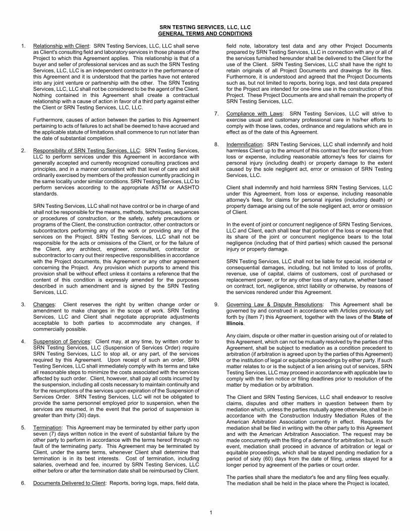
SRN TESTING SERVICES, LLC, LLC GENERAL TERMS AND CONDITIONS
1. Relationship with Client: SRN Testing Services, LLC, LLC shall serveas Client's consulting field and laboratory services in those phases of theProject to which this Agreement applies. This relationship is that of abuyer and seller of professional services and as such the SRN TestingServices, LLC, LLC is an independent contractor in the performance ofthis Agreement and it is understood that the parties have not enteredinto any joint venture or partnership with the other. The SRN TestingServices, LLC, LLC shall not be considered to be the agent of the Client.Nothing contained in this Agreement shall create a contractualrelationship with a cause of action in favor of a third party against eitherthe Client or SRN Testing Services, LLC, LLC.
Furthermore, causes of action between the parties to this Agreementpertaining to acts of failures to act shall be deemed to have accrued andthe applicable statute of limitations shall commence to run not later thanthe date of substantial completion.
2. Responsibility of SRN Testing Services, LLC: SRN Testing Services,LLC to perform services under this Agreement in accordance withgenerally accepted and currently recognized consulting practices andprinciples, and in a manner consistent with that level of care and skillordinarily exercised by members of the profession currently practicing inthe same locality under similar conditions. SRN Testing Services, LLC toperform services according to the appropriate ASTM or AASHTOstandards.
SRN Testing Services, LLC shall not have control or be in charge of andshall not be responsible for the means, methods, techniques, sequencesor procedures of construction, or the safety, safety precautions orprograms of the Client, the construction contractor, other contractors orsubcontractors performing any of the work or providing any of theservices on the Project. SRN Testing Services, LLC shall not beresponsible for the acts or omissions of the Client, or for the failure ofthe Client, any architect, engineer, consultant, contractor orsubcontractor to carry out their respective responsibilities in accordancewith the Project documents, this Agreement or any other agreementconcerning the Project. Any provision which purports to amend thisprovision shall be without effect unless it contains a reference that thecontent of this condition is expressly amended for the purposesdescribed in such amendment and is signed by the SRN TestingServices, LLC.
3. Changes: Client reserves the right by written change order oramendment to make changes in the scope of work. SRN TestingServices, LLC and Client shall negotiate appropriate adjustmentsacceptable to both parties to accommodate any changes, ifcommercially possible.
4. Suspension of Services: Client may, at any time, by written order toSRN Testing Services, LLC (Suspension of Services Order) requireSRN Testing Services, LLC to stop all, or any part, of the servicesrequired by this Agreement. Upon receipt of such an order, SRNTesting Services, LLC shall immediately comply with its terms and takeall reasonable steps to minimize the costs associated with the servicesaffected by such order. Client, however, shall pay all costs incurred bythe suspension, including all costs necessary to maintain continuity andfor the resumptions of the services upon expiration of the Suspension ofServices Order. SRN Testing Services, LLC will not be obligated toprovide the same personnel employed prior to suspension, when theservices are resumed, in the event that the period of suspension isgreater than thirty (30) days.
5. Termination: This Agreement may be terminated by either party uponseven (7) days written notice in the event of substantial failure by theother party to perform in accordance with the terms hereof through nofault of the terminating party. This Agreement may be terminated byClient, under the same terms, whenever Client shall determine thattermination is in its best interests. Cost of termination, includingsalaries, overhead and fee, incurred by SRN Testing Services, LLCeither before or after the termination date shall be reimbursed by Client.
6. Documents Delivered to Client: Reports, boring logs, maps, field data,
field note, laboratory test data and any other Project Documents prepared by SRN Testing Services, LLC in connection with any or all of the services furnished hereunder shall be delivered to the Client for the use of the Client. SRN Testing Services, LLC shall have the right to retain originals of all Project Documents and drawings for its files. Furthermore, it is understood and agreed that the Project Documents such as, but not limited to reports, boring logs, and test data prepared for the Project are intended for one-time use in the construction of this Project. These Project Documents are and shall remain the property of SRN Testing Services, LLC.
7. Compliance with Laws: SRN Testing Services, LLC will strive toexercise usual and customary professional care in his/her efforts tocomply with those laws, codes, ordinance and regulations which are ineffect as of the date of this Agreement.
8. Indemnification: SRN Testing Services, LLC shall indemnify and holdharmless Client up to the amount of this contract fee (for services) fromloss or expense, including reasonable attorney's fees for claims forpersonal injury (including death) or property damage to the extentcaused by the sole negligent act, error or omission of SRN TestingServices, LLC.
Client shall indemnify and hold harmless SRN Testing Services, LLCunder this Agreement, from loss or expense, including reasonableattorney's fees, for claims for personal injuries (including death) orproperty damage arising out of the sole negligent act, error or omissionof Client.
In the event of joint or concurrent negligence of SRN Testing Services,LLC and Client, each shall bear that portion of the loss or expense thatits share of the joint or concurrent negligence bears to the totalnegligence (including that of third parties) which caused the personalinjury or property damage.
SRN Testing Services, LLC shall not be liable for special, incidental orconsequential damages, including, but not limited to loss of profits,revenue, use of capital, claims of customers, cost of purchased orreplacement power, or for any other loss of any nature, whether basedon contract, tort, negligence, strict liability or otherwise, by reasons ofthe services rendered under this Agreement.
9. Governing Law & Dispute Resolutions: This Agreement shall begoverned by and construed in accordance with Articles previously setforth by (Item 7) this Agreement, together with the laws of the State ofIllinois.
Any claim, dispute or other matter in question arising out of or related tothis Agreement, which can not be mutually resolved by the parties of thisAgreement, shall be subject to mediation as a condition precedent toarbitration (if arbitration is agreed upon by the parties of this Agreement)or the institution of legal or equitable proceedings by either party. If suchmatter relates to or is the subject of a lien arising out of services, SRNTesting Services, LLC may proceed in accordance with applicable law to comply with the lien notice or filing deadlines prior to resolution of thematter by mediation or by arbitration.
The Client and SRN Testing Services, LLC shall endeavor to resolveclaims, disputes and other matters in question between them bymediation which, unless the parties mutually agree otherwise, shall be inaccordance with the Construction Industry Mediation Rules of theAmerican Arbitration Association currently in effect. Requests formediation shall be filed in writing with the other party to this Agreementand with the American Arbitration Association. The request may bemade concurrently with the filing of a demand for arbitration but, in suchevent, mediation shall proceed in advance of arbitration or legal orequitable proceedings, which shall be stayed pending mediation for aperiod of sixty (60) days from the date of filing, unless stayed for alonger period by agreement of the parties or court order.
The parties shall share the mediator's fee and any filing fees equally.The mediation shall be held in the place where the Project is located,
1

unless another location is mutually agreed upon. Agreements reached in mediation shall be enforceable as settlement agreements in any court having jurisdiction thereof.
10. Waiver of Contract Breach: The waiver of one party of any breach ofthis Agreement or the failure of one party to enforce at any time, or forany period of time, any of the provisions hereof, shall be limited to theparticular instance, shall not operate or be deemed to waive any futurebreaches of this Agreement and shall not be construed to be a waiver ofany provision, except for the particular instance.
11. Entire Understanding of Agreement: This Agreement represents andincorporates the entire understanding of the parties hereto, and eachparty acknowledges that there are no warranties, representations,covenants or understandings of any kind, matter or descriptionwhatsoever, made by either party to the other except as expressly setforth herein. Client and SRN Testing Services, LLC hereby agree thatany purchase orders, invoices, confirmations, acknowledgments or other similar documents executed or delivered with respect to the subjectmatter hereof that conflict with the terms of the Agreement shall be null,void and without effect to the extent they conflict with the terms of thisAgreement.
12. Amendment: This Agreement shall not be subject to amendment unlessanother instrument is duly executed by duly authorized representativesof each of the parties and entitled "Amendment of Agreement".
13. Severability of Invalid Provisions: If any provision of the Agreementshall be held to contravene or to be invalid under the laws of anyparticular state, county or jurisdiction where used, such contraventionshall not invalidate the entire Agreement, but it shall be construed as ifnot containing the particular provisions held to be invalid in the particularstate, country or jurisdiction and the rights or obligations of the partieshereto shall be construed and enforced accordingly.
14. Force Majeure: Neither Client nor SRN Testing Services, LLC shall beliable for any fault or delay caused by any contingency beyond theircontrol including but not limited to acts of God, wars, strikes, walkouts,fires, natural calamities, or demands or requirements of governmentalagencies.
15. Access to Site: Client shall arrange for SRN Testing Services, LLC toenter upon public and private property and obtain all necessaryapprovals and permits required from all governmental authorities havingjurisdiction over the Project. SRN Testing Services, LLC shall takeprecautions to minimize damage, but SRN Testing Services, LLC hasnot included the cost of restoration of damage to site. The Client is toadvise SRN Testing Services, LLC of any known utility lines orunderground structures at any site which SRN Testing Services, LLCshall be performing services. SRN Testing Services, LLC’ responsibilitywith concerning underground utilities is to contact the Illinois Joint UtilityLocation Information for Excavators for the location of public, but notprivate utilities.
16. Hazardous Material: SRN Testing Services, LLC shall have noresponsibility for the discovery, presence, handling, removal or disposalof or exposure of persons to hazardous materials/pollutants in any format the Project site. SRN Testing Services, LLC shall notify Clientregarding discovery of hazardous waste.
17. Designation of Authorized Representative: Each party (to thisAgreement) shall designate one or more persons to act with authority inits behalf in respect to appropriate aspects of the Project. The personsdesignated shall review and respond promptly to all communicationsreceived from the other party.
18. Limit of Liability: The Client and the SRN Testing Services, LLC havediscussed the risks, rewards, and benefits of the project and SRNTesting Services, LLC’ total fee for services. In recognition of therelative risks and benefits of the Project to both the Client and the SRNTesting Services, LLC, the risks have been allocated such that the Clientagrees that to the fullest extent permitted by law, SRN Testing Services,LLC’ total aggregate liability to the Client for any and all injuries, claims,costs, losses, expenses, damages of any nature whatsoever or claimexpenses arising out of this Agreement from any cause or causes,including attorney's fees and costs, and expert witness fees and costs,shall not exceed the total of SRN Testing Services, LLC 's fee forconsulting field and laboratory services rendered on this project as made
part of this Agreement. Such causes included but are not limited to SRN Testing Services, LLC’ negligence, errors, omissions, strict liability or breach of contract. It is intended that this limitation apply to any and all liability or cause of action however alleged or arising, unless otherwise prohibited by law.
19. Information Provided by Others: SRN Testing Services, LLC shallindicate to the Client the information needed for rendering of theservices of this Agreement. The Client shall provide to the SRN TestingServices, LLC such information as is available to the Client and theClient's consultants and contractors, and SRN Testing Services, LLCshall be entitled to rely upon the accuracy and completeness thereof.The Client recognizes that it is impossible for the Engineer to assure the accuracy, completeness and sufficiency of such information, eitherbecause it is impossible to verify, or because of errors or omissionswhich may have occurred in assembling the information the Client isproviding. Accordingly, the Client agrees, to the fullest extent permittedby law, to indemnify and hold the SRN Testing Services, LLC and SRNTesting Services, LLC’ subconsultants harmless from any claim, liabilityor cost (including reasonable attorneys' fees and cost of defense) forinjury or loss arising or allegedly arising from errors, omissions orinaccuracies in documents or other information provided by the Client tothe Engineer.
20. Payment: Client shall be invoiced once each month for work performedduring the preceding period. Client agrees to pay each invoice withinthirty (30) days of its receipt. The client further agrees to pay interest onall amounts invoiced and not paid or objected to for valid cause withinsaid thirty (30) day period at the rate of eighteen (18) percent per annum(or the maximum interest rate permitted under applicable law, whicheveris the lesser) until paid. Client further agrees to pay Engineer's cost ofcollection of all amounts due and unpaid after sixty (60) days, includingcourt costs and reasonable attorney's fees, as well as costs attributed tosuspension of services accordingly and as follows:
Collection Costs. In the event legal action is necessary to enforce thepayment provisions of this Agreement, SRN Testing Services, LLC shallbe entitled to collect from the Client any judgment or settlement sumsdue, reasonable attorneys' fees, court costs and expenses incurred bySRN Testing Services, LLC in connection therewith and, in addition, thereasonable value of the SRN Testing Services, LLC’ time and expensesspent in connection with such collection action, computed at the SRNTesting Services, LLC’ prevailing fee schedule and expense policies.
Suspension of Services. If the Client fails to make payments when dueor otherwise is in breach of this Agreement, SRN Testing Services, LLCmay suspend performance of services upon five (5) calendar days'notice to the Client. SRN Testing Services, LLC shall have no liabilitywhatsoever to the Client for any costs or damages as a result of suchsuspension caused by any breach of this Agreement by the Client.Client will reimburse SRN Testing Services, LLC for all associated costsas previously set forth in this Agreement.
21. When construction observation tasks are part of the service to beperformed by SRN Testing Services, LLC under this Agreement, theClient will include the following clause in the construction contractdocuments and Client agrees not to modify or delete it:
Kotecki Waiver. Contractor (and any subcontractor into whose subcontract this clause is incorporated) agrees to assume the entire liability for all personal injury claims suffered by its own employees, including without limitation claims under the Illinois Structural Work Act, asserted by persons allegedly injured on the Project; waives any limitation of liability defense based upon the Worker's Compensation Act, court interpretations of said Act or otherwise; and to the fullest extent permitted by law, agrees to indemnify and hold harmless and defend Owner and Engineer and their agents, employees and consultants (the "Indemnitees") from and against all such loss, expense, damage or injury, including reasonable attorneys' fees, that the Indemnitees may sustain as a result of such claims, except to the extent that Illinois law prohibits indemnity for the Indemnitees' own negligence. “The Owner and Engineer are designated and recognized as explicit third-party beneficiaries of the Kotecki Waiver within the general contract and all subcontracts entered into in furtherance of the general contract.”
2