soils compaction and testing · pdf filesoils compaction and testing 2015 ... project plan...
TRANSCRIPT
CONSTRUCTION INSPECTOR’S
REFERENCE MANUAL
SOILS COMPACTION
AND TESTING
2015
Technical Training & Certification Program


Table of Contents
I. Iowa DOT Information
a. Specifications
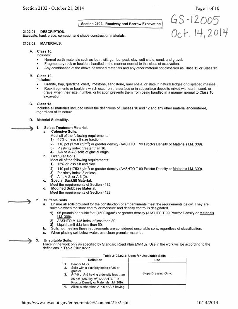
i. Portion of Section 2102
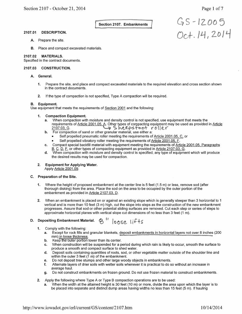
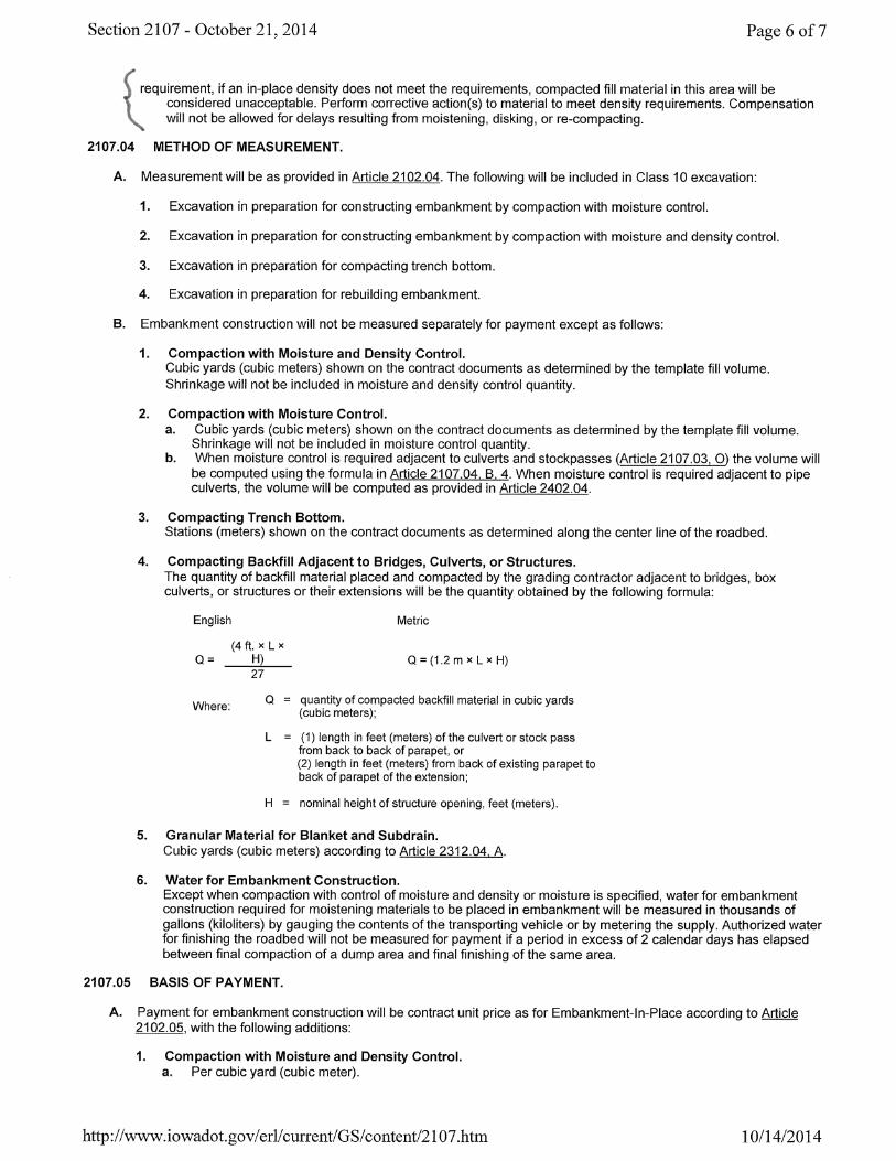
ii. Section 2107
b. Standard Road Plans
i. EW-102
ii. EW-103
c. IM 309 Determining Standard Proctor Moisture Density Relationship of Soils
d. IM 312 Sampling of Soils for Construction Project
e. IM 335 Determining Moisture Content of Soils
f. IM 540 Quality Management & Acceptance – Embankment Construction
g. Other IM’s
i. IM 204 Appendix A – Roadway & Borrow Excavation & Embankments
ii. IM 208 – Materials Laboratory Qualification Program (pages with soils items)
iii. IM 213 Appendix D – Soils Technician Duties
iv. IM 216 – Guidelines for Determining the Acceptability of Test Results
v. IM 326 – Determining the Density of Undisturbed Soil Cores by Displacement
vi. IM 334 – Determining Moisture Content & Density of Soils, Bases & Subbases
with a Nuclear Gauge
h. Documentation
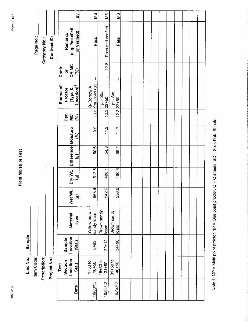
i. E107 Field Moisture Test
ii. E108 Proctor Tests
iii. Form 821258 Nuclear Test Report
iv. Proctor Density Calculation Spreadsheet
v. Random Sampling Worksheet
vi. Soil Field Lab Inspection QC Checklist
vii. Sample E107
viii. Materials 101 Form - Excavation
II. Other Reference Information
a. Nuclear Method Information – AASHTO T310


SPEC
IFICA
TION
S


STAN
DA
RD
R
OA
D PLA
NS

Pro
posed P
avem
ent
Full
Should
er
Wid
th o
f R
oadw
ay
C L
Fin
ished G
radeli
ne
5.0
' M
in.
Top o
f S
ubgra
de
Fo
reslo
pe
Norm
al
Suit
able
Mate
rial
(8''
Min
. th
ickness)
Ori
gin
al
Gro
und
Fo
reslo
pe
Norm
al
Full
Sh
ou
lder
Wid
th o
f R
oad
way
Pro
posed P
avem
ent
C L
Fin
ished G
radeli
ne
5.0
' M
in.
Fo
reslo
pe
Norm
al
Top o
f S
ubgra
de
Fo
reslo
pe
Norm
al
Ori
gin
al
Gro
und
Fo
reslo
pe
Norm
al
Pro
posed P
avem
ent
Full
Should
er
Wid
th o
f R
oadw
ay
Full
Should
er
Wid
th o
f R
oadw
ay
Pro
posed P
avem
ent
Top o
f S
ubgra
de
3.0
' M
in.
Fin
ished G
radeli
ne
C L
Fo
reslo
pe
Norm
al
Ori
gin
al
Gro
und
Full
Should
er
Wid
th o
f R
oadw
ay
Pro
posed P
avem
ent
C L
Fin
ished G
radeli
ne
Fo
reslo
pe
Norm
al
Top o
f S
ubgra
de
Fo
reslo
pe
Norm
al
Ori
gin
al
Gro
und
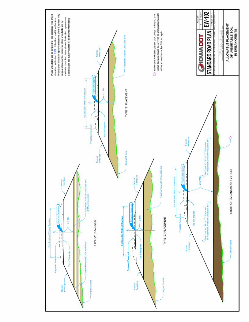
wil
l be a
llow
ed b
elo
w t
hat
20 f
oot
depth
.
Sele
ct,
Su
itab
le C
lass 1
0,
or
Ty
pe 'C
' U
nsu
itab
le m
ate
rial
In n
ew
em
ban
km
en
ts g
reate
r th
an
20
feet
in h
eig
ht,
on
ly
1
1
21
02
21
02
secti
on
s a
nd
so
il s
urv
ey
sh
eets
fo
r ad
dit
ion
al
info
rmati
on
.
meth
ods o
ther
than t
hose s
how
n. R
efe
r als
o t
o p
lan c
ross
req
uir
e p
lacem
en
t o
f to
pso
il o
r o
ther
un
su
itab
le s
oil
by
Pro
ject
pla
n d
eta
ils o
r specif
ic d
irecti
ons o
f th
e E
ngin
eer
may
of
the S
tandard
Specif
icati
ons.
descri
bed i
n S
ecti
on
Pla
ce u
nsu
itab
le s
oil
as d
eta
iled
fo
r th
e p
art
icu
lar
typ
e o
f so
il
TY
PE
"A
" P
LA
CE
ME
NT
TY
PE
"B
" P
LA
CE
ME
NT
TY
PE
"C
" P
LA
CE
ME
NT
20.0
' M
ax.
HE
IGH
T O
F E
MB
AN
KM
EN
T >
20 F
EE
T
EW
-102
RE
VIS
ION
10
-21
-14
SH
EE
T 1
of
1
RE
VIS
ION
S:A
dd
ed
HE
IGH
T O
F E
MB
AN
KM
EN
T >
20
FE
ET
dra
win
g a
nd
cir
cle
no
te 1
.
AP
PR
OV
ED
BY
DE
SIG
N M
ET
HO
DS
EN
GIN
EE
R
STA
ND
AR
D R
OA
D P
LAN
1
IN E
MB
AN
KM
EN
TS
OF
UN
SU
ITA
BL
E S
OIL
AL
LO
WA
BL
E P
LA
CE
ME
NT
(8''
Max
. th
ick
ness)
Pla
cem
ent
Are
a f
or
Unsuit
able
Soil
Pla
cem
ent
Are
a f
or
Unsuit
able
Soil
Pla
cem
ent
Are
a f
or
Unsuit
able
Soil
for
Pla
cem
en
t A
reas f
or
Un
su
itab
le S
oil
See T
ype "
A", "B
", or
"C
" P
lacem
ent
for
Pla
cem
en
t A
reas f
or
Un
su
itab
le S
oil
See T
ype "
A", "B
", or
"C
" P
lacem
ent


C L C L C LC L C L
TO
TE
MP
LA
TE
QU
AN
TIT
YT
YP
E O
F W
OR
K
Ex
cav
ati
on
Em
ban
km
en
t
Subgra
de T
reatm
ent
3 , 4
21
AR
EA
NO
.(T
em
pla
te)
Top o
f S
ubgra
de
Pavem
ent
Wid
th +
Should
er
Wid
th
DE
SIG
N W
IDT
H
Pav
em
en
t
Su
bb
ase
Foreslope
Top o
f P
avem
ent
Depth
Foreslope
Natu
ral
Gro
und
Foreslope
Depth
DE
SIG
N W
IDT
H Top o
f P
avem
ent
(Tem
pla
te)
Top o
f S
ubgra
de
Foreslope
(Tem
pla
te)
Top o
f S
ubgra
de
Pavem
ent
Wid
th +
Should
er
Wid
th
DE
SIG
N W
IDT
H
Natu
ral
Gro
und
Top o
f P
avem
ent
Foreslope
Depth
6''
Foreslope
(Tem
pla
te)
Top o
f S
ubgra
de
Foreslope
12
''
DE
SIG
N W
IDT
H Top o
f P
avem
ent
Depth
6''
Foreslope
(Tem
pla
te)
Top o
f S
ubgra
de
Foreslope
6''
DE
SIG
N W
IDT
H Top o
f P
avem
ent
Depth
6''
Foreslope
TY
PE
OF
WO
RK
AR
EA
NO
.
Ex
cav
ati
on
Em
ban
km
en
t
Subgra
de T
reatm
ent
TY
PE
OF
WO
RK
AR
EA
NO
.
Ex
cav
ati
on
Em
bankm
ent
M &
D E
mb
an
km
en
t
Scari
fy w
ith M
& D
Em
bank.
TY
PE
OF
WO
RK
Ex
cav
ati
on
Scari
fy
AR
EA
NO
.
None
None
AR
EA
NO
.
TY
PE
OF
AD
JUS
TM
EN
TS
TO
TE
MP
LA
TE
QU
AN
TIT
Y
wid
th p
lus 3
.0 f
eet
on e
ach s
ide.
Desig
n w
idth
equals
pavem
ent
TO
TE
MP
LA
TE
QU
AN
TIT
Y
TY
PE
OF
AD
JUS
TM
EN
TS
AR
EA
NO
.
+ C
ut
+ F
ill
None
None
None
+ C
ut
+ F
ill
None
None
TO
TE
MP
LA
TE
QU
AN
TIT
Y
TY
PE
OF
AD
JUS
TM
EN
TS
AR
EA
NO
.
- F
ill
+ C
ut
None
None
TY
PE
OF
AD
JUS
TM
EN
TS
TO
TE
MP
LA
TE
QU
AN
TIT
YA
RE
A
NO
.
TY
PE
OF
AD
JUS
TM
EN
TS
AR
EA
NO
.
None
None
+ C
ut
- F
ill
21 3 4
1
34
2
B
3 , 4
21
2
43
1
4321
1 , 3
2 , 4
3 , 4
5
24
3
5
11 2 3 4 5
B
11 2
2
1 2
B
21
B
1 2
(Exis
ting R
oadw
ays)
TR
EN
CH
BO
TT
OM
CO
MP
AC
TIO
N
MO
IST
UR
E C
ON
TR
OL
OR
MO
IST
UR
E A
ND
DE
NS
ITY
CO
NT
RO
L
(Exis
ting R
oadw
ay)
SP
EC
IAL
CO
MP
AC
TIO
N
SU
BG
RA
DE
TR
EA
TM
EN
T
TR
EN
CH
SU
BG
RA
DE
TR
EA
TM
EN
T
ST
AN
DA
RD
Natu
ral
Gro
und
TY
PE
OF
WO
RK
Ex
cav
ati
on
Scari
fy
AR
EA
NO
.
1 2
ab
so
lute
vo
lum
e f
or
the s
pecif
ied
dep
th a
nd
su
bg
rad
e w
idth
.
Contr
ol"
or
"C
om
pacti
on w
ith M
ois
ture
Contr
ol"
wil
l be t
he
Th
e p
ay
qu
an
tity
fo
r "C
om
pacti
on
wit
h M
ois
ture
an
d D
en
sit
y
the t
reatm
ent
type, and i
nclu
des t
he q
uanti
ty f
or
shri
nkage.
or
cu
bic
yard
s.
Th
e v
olu
me w
ill
be b
ased
on
sp
ecif
ied
dep
th,
Th
e p
ay
qu
an
tity
fo
r S
ub
gra
de T
reatm
en
t w
ill
be i
n e
ith
er
ton
s
103-6
103-3
103-1
Po
ssib
le T
ab
ula
tio
ns:
Specia
l C
om
pacti
on o
f S
ubgra
de
Com
pacti
ng T
rench B
ott
om
Com
pacti
on w
ith M
ois
ture
Contr
ol
Com
pacti
on w
ith M
ois
ture
and D
ensit
y C
ontr
ol
Possib
le C
ontr
act
Item
s:
EW
-103
RE
VIS
ION
10
-15
-13
SH
EE
T 1
of
1
RE
VIS
ION
S:N
ew
. R
ep
laces R
L-2
A.
AP
PR
OV
ED
BY
DE
SIG
N M
ET
HO
DS
EN
GIN
EE
R
STA
ND
AR
D R
OA
D P
LAN
New
CO
NT
RO
L A
ND
SP
EC
IAL
CO
MP
AC
TIO
N
TR
EA
TM
EN
T, M
OIS
TU
RE
DE
NS
ITY
EM
BA
NK
ME
NT
SU
BG
RA
DE


IM
309
PR
OC
TO
R D
EN
SIT
Y

April 16, 2013 Matls. IM 309 Supersedes April 17, 2012
1
Office of Materials
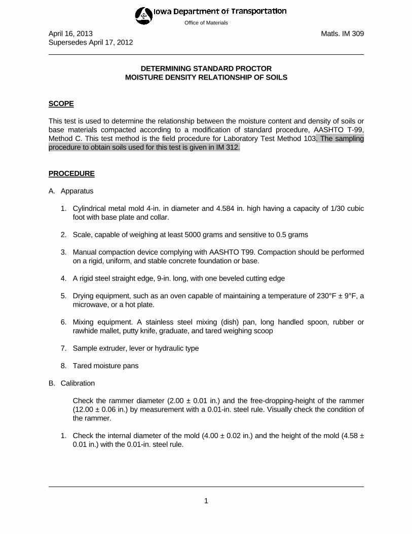
DETERMINING STANDARD PROCTOR MOISTURE DENSITY RELATIONSHIP OF SOILS
SCOPE This test is used to determine the relationship between the moisture content and density of soils or base materials compacted according to a modification of standard procedure, AASHTO T-99, Method C. This test method is the field procedure for Laboratory Test Method 103. The sampling procedure to obtain soils used for this test is given in IM 312. PROCEDURE A. Apparatus
1. Cylindrical metal mold 4-in. in diameter and 4.584 in. high having a capacity of 1/30 cubic foot with base plate and collar.
2. Scale, capable of weighing at least 5000 grams and sensitive to 0.5 grams 3. Manual compaction device complying with AASHTO T99. Compaction should be performed
on a rigid, uniform, and stable concrete foundation or base. 4. A rigid steel straight edge, 9-in. long, with one beveled cutting edge 5. Drying equipment, such as an oven capable of maintaining a temperature of 230°F ± 9°F, a
microwave, or a hot plate. 6. Mixing equipment. A stainless steel mixing (dish) pan, long handled spoon, rubber or
rawhide mallet, putty knife, graduate, and tared weighing scoop 7. Sample extruder, lever or hydraulic type 8. Tared moisture pans
B. Calibration
Check the rammer diameter (2.00 ± 0.01 in.) and the free-dropping-height of the rammer (12.00 ± 0.06 in.) by measurement with a 0.01-in. steel rule. Visually check the condition of the rammer.
1. Check the internal diameter of the mold (4.00 ± 0.02 in.) and the height of the mold (4.58 ±
0.01 in.) with the 0.01-in. steel rule.

April 16, 2013 Matls. IM 309 Supersedes April 17, 2012
2
C. Sample Preparation
1. Quarter the field sample to a representative sample of about 5000 grams. Spread out and allow to dry to a moisture content at least 5% below the estimated optimum moisture content.
2. Screen the sample over a 3/4-inch sieve and replace the aggregate retained with an equal
weight of No. 4 to 3/4 in. aggregate from the same source, or break up the material larger than ¾” to pass the ¾” sieve and return it to the sample.
D. Test Procedure
1. Pulverize the prepared sample so that at least 90% of all non-aggregate material will pass the No. 4 sieve. Place the sample in the mixing pan and sprinkle sufficient water to dampen it to approximately 4% below optimum moisture content. The sample is ready for test when, after thorough mixing, a handful of soil squeezed tightly in the palm will barely hold together when pinched between the fingers.
2. Form a specimen by compacting the prepared soil in the mold in three approximately equal
layers. Weigh in a tared scoop, and place loose soil in the assembled mold and spread into a layer of uniform thickness. Lightly tamp the soil prior to compaction until it is not in a loose state. Place the mold under the hammer for compaction. Deliver twenty-five uniformly distributed blows. Measure to determine if there is a deviation from the needed 1/3 height in the mold. Adjust the weight of soil taken for the second layer as needed to give the desired height, and compact the same as with the first layer. Following compaction of each of the first two layers, any soil adjacent to the mold walls that has not been compacted or extends above the compacted surface shall be trimmed. Repeat this process for a third layer. During this entire operation, do not allow sample to accumulate on the bottom of the hammer. After compaction of the final layer, the sample should extend 0.1 to 0.4 in. above the height of the mold.
3. Move the mold and contents to a table, remove the collar with a twisting motion and cut
off the excess sample in thin layers with the straightedge. If the soil projects more than 0.4 in. above the mold or if the mold is not completely filled, the compactive effort is incorrect and the compacted specimen must be extruded, pulverized, and returned to the mixing pan. After remixing, adjust the weight for each layer as needed and recompact by the same procedure. Replace any small aggregate, which are pulled from the surface with finer hand tamped material. Leave in place large, well-embedded aggregate, and finish the top to arrive at a surface that will average level full.
4. Detach the mold from the base plate and determine the mass of the mold and compacted
soil. Extrude the specimen from the mold. Slice vertically through the center of the specimen. Place into a weighted pan at least a 500 gram moisture sample from one of the cut faces. Follow IM 335 to determine moisture content. Pulverize the remaining portion of the specimen and return to the mixing pan.

April 16, 2013 Matls. IM 309 Supersedes April 17, 2012
3
5. Sprinkle the sample with water, not to exceed 2% of the remaining sample weight, and
thoroughly mix until moisture uniformity is reached. The compaction and moisture determination for this moisture content is the same as for the first. Repeat this procedure of adding water, compacting a specimen and taking a moisture sample while increasing the moisture content until a compacted weight is reached that is no more than 20 grams higher than the preceding one. This signifies that the resultant moisture density curve is past the optimum percent moisture. Since the proctor curve is based on dry density, each 2% moisture increase is the equivalent of approximately 30 grams for a proctor specimen. Thus if the last specimen is only 20 grams heavier than the previous (2% drier) point, this will show a reduced dry density.
E. Calculations
(100) (pan) - pan) soil(Dry
pan) soil(Dry - pan) soil (Wet Moisture %
Example: 13.8% (100)170 - 460460 - 500 Moisture %
Compacted Dry Density for kg/m3
(100)100) Moisture (%
0.06614 x soil compacted Mass WetNet
Example:
Compacted Dry Density for lb./ft.3
3lb./ft. 115.2 )100(100) (13.86614)(1983)(0.0
F. Moisture-Density Relationship
1. Make the preceding calculations for each compacted specimen at each corresponding moisture content.
2. Using these results, plot points with densities (dry weight per cubic foot) as ordinates
(vertical) and percent of moisture as abscissas (horizontal). 3. Use the resulting points to draw a smooth curve. The peak of the curve will give the
maximum, or Proctor density and the corresponding optimum moisture content.

April 16, 2013 Matls. IM 309 Supersedes April 17, 2012
4
G. One-Point Procedure
1. Grade material other than crushed stone, gravel, black soils, or soils containing a considerable amount of aggregate may be tested for maximum density and optimum moisture according to this procedure. Those excluded above shall be run as in "D", "E", and "F" above.
2. Moisten a representative sample of approximately 3000 grams to an estimated moisture
content of two to three percentage points below Proctor optimum moisture. 3. Following the procedure outlined in D2 through D4, compact and obtain net wet weight of a
single specimen at the moisture content in G2. Determine the moisture content and wet density (in pounds per cubic foot) for this single compacted specimen.
4. In the family of curves, plot the point of intersection of the above wet weight and moisture. If
the plotted point falls outside the "Range of Confidence," recompact another specimen at an adjusted moisture content that will place the plot within these bounds.
5. Using the number of the nearest curve, obtain the dry Proctor density and optimum moisture
values from the attached table.
H. Calculations for One-Point Test
Calculate the moisture content and wet weight of sample per cubic foot as follows:
100 x C - BB -A w )(0.06614 W W 3
12
Where: w = Percentage of moisture in the specimen, based on oven dry weight of soil. A = Weight of moisture pan plus wet soil. B = Weight of moisture pan plus dry soil. C = Weight of moisture pan. W1 = Wet weight, in grams, of compacted specimen. W2 = Wet weight, in pounds per cubic foot of compacted specimen.

April 16, 2013 Matls. IM 309 Supersedes April 17, 2012
5
Maximum Density Curve
109
110
111
112
113
114
115
116
117
9 10 11 12 13 14 15 16Moisture (%)
Dry
Den
sity
(Lb
/ft3 )
Opt
. Moi
st. C
onte
nt =
13.
8%
Maxim um Density = 115.2 lb/ft3
April 16, 2013 Matls. IM 309 Supersedes April 17, 2012
6
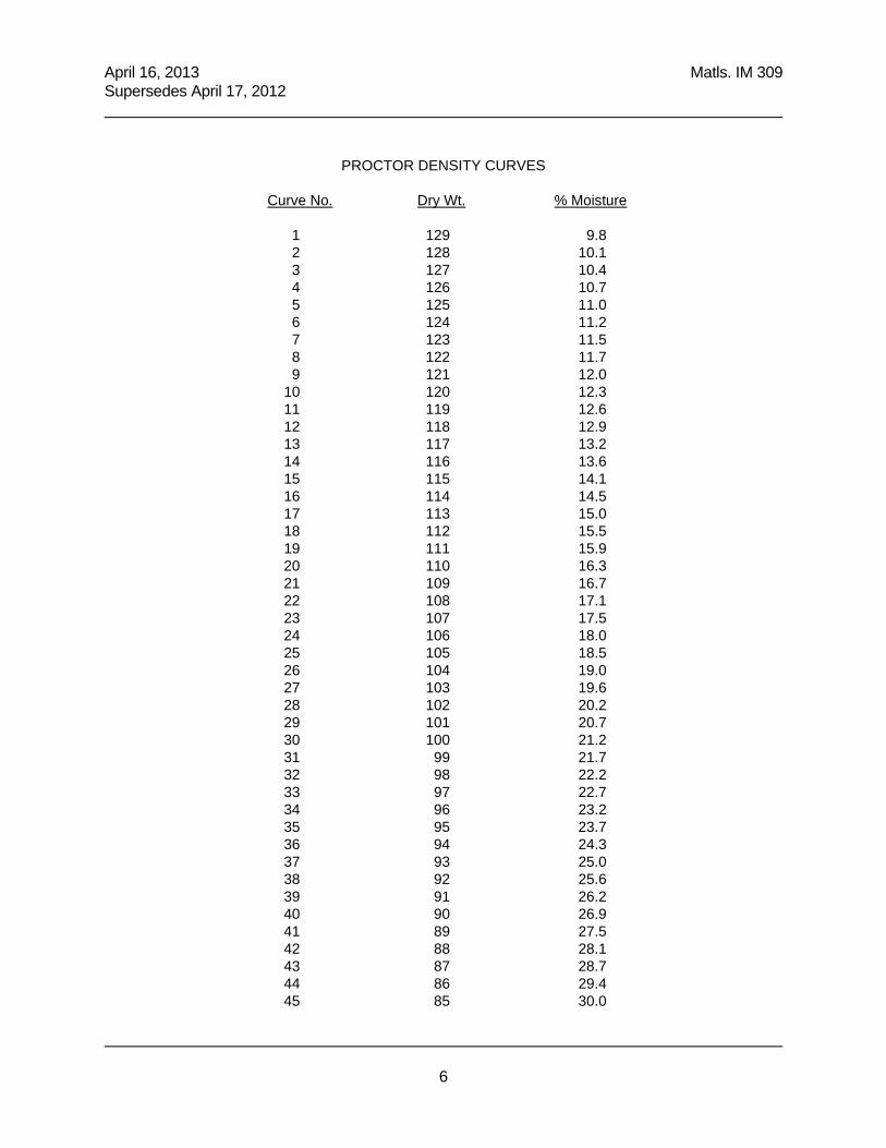
PROCTOR DENSITY CURVES
Curve No. Dry Wt. % Moisture 1 129 9.8 2 128 10.1 3 127 10.4 4 126 10.7 5 125 11.0 6 124 11.2 7 123 11.5 8 122 11.7 9 121 12.0 10 120 12.3 11 119 12.6 12 118 12.9 13 117 13.2 14 116 13.6 15 115 14.1 16 114 14.5 17 113 15.0 18 112 15.5 19 111 15.9 20 110 16.3 21 109 16.7 22 108 17.1 23 107 17.5 24 106 18.0 25 105 18.5 26 104 19.0 27 103 19.6 28 102 20.2 29 101 20.7 30 100 21.2 31 99 21.7 32 98 22.2 33 97 22.7 34 96 23.2 35 95 23.7 36 94 24.3 37 93 25.0 38 92 25.6 39 91 26.2 40 90 26.9 41 89 27.5 42 88 28.1 43 87 28.7 44 86 29.4 45 85 30.0

April 16, 2013 Matls. IM 309 Supersedes April 17, 2012
7


IM 3
12
S
AM
PL
ING


April 16, 2013 Matls. IM 312 New Issue
1
Office of Materials
****THIS IS A NEW IM. – PLEASE READ CAREFULLY.****
SAMPLING OF SOILS FOR CONSTRUCTION PROJECT
GENERAL This method describes the procedure for sampling soils on construction sites. The obtained sample will be used for the proctor test (IM 309), for the measurement of moisture content (IM 335), or nuclear gauge moisture correction (IM 334). The intent of sampling is to obtain a suitable amount of soils from the earth with as little disturbance as possible to the natural density, moisture content, and structural arrangement of the particles. A representative sample of soil shall be a combination of the various particles in the same proportion as they exist in the natural ground, roadway or pit. Representative samples should also contain only materials of like color and texture, and should not be a composite of materials apparently different in character. Soil samples can be collected by using a spade, shovel, or auger, depending on the terrain, the soil type, and the depth of material below the surface. SAMPLING PROCEDURE FOR THE PROCTOR TEST The sample consists of a composite of four approximately equal volume samples from select locations within the area under investigation. The recommended minimum sample size is 25 pounds which is sufficient for a four-point test in field.
Select four representative locations within the sampling area. Identify the layer of soils needed to be sampled. Remove soils above the sampling layer. Take approximately a quarter of the sample from each the selected locations by using a
proper tool. Place the four obtained samples into a bag or other acceptable container. These
samples will be combined into a composite sample. Label the sample with a proper ID.
SAMPLING PROCEDURE FOR THE MOISURE TEST The recommended minimum sample size is 3.0 pounds.
Select a random location in the sampling area. Sample will be comprised of soil from three locations at this station, the center and the ¼ points from each side of the center.
Identify the layer of soils needed to be sampled. Remove soils above the sampling layer. Take approximately one-third of the sample from each the selected locations by using a
spade or shovel. Composite the soils taken from these three locations.
April 16, 2013 New Issue Matls. IM 312 ______________________________________________________________________________
2
Before performing the test, reduce the sample size to 1.1 lbs by quartering or other acceptable method.
Place the obtained sample in a proper bag or container to prevent moisture loss if the test is not immediately performed.
Label the sample with a proper ID. Because moisture content may vary significantly over a project site, several samples and tests may be needed in order to obtain more realistic result of moisture content.

IM
335
M
OIS
TU
RE
CO
NT
EN
T

April 16, 2013 Matls. IM 335 Supersedes April 17, 2012
1
Office of Materials
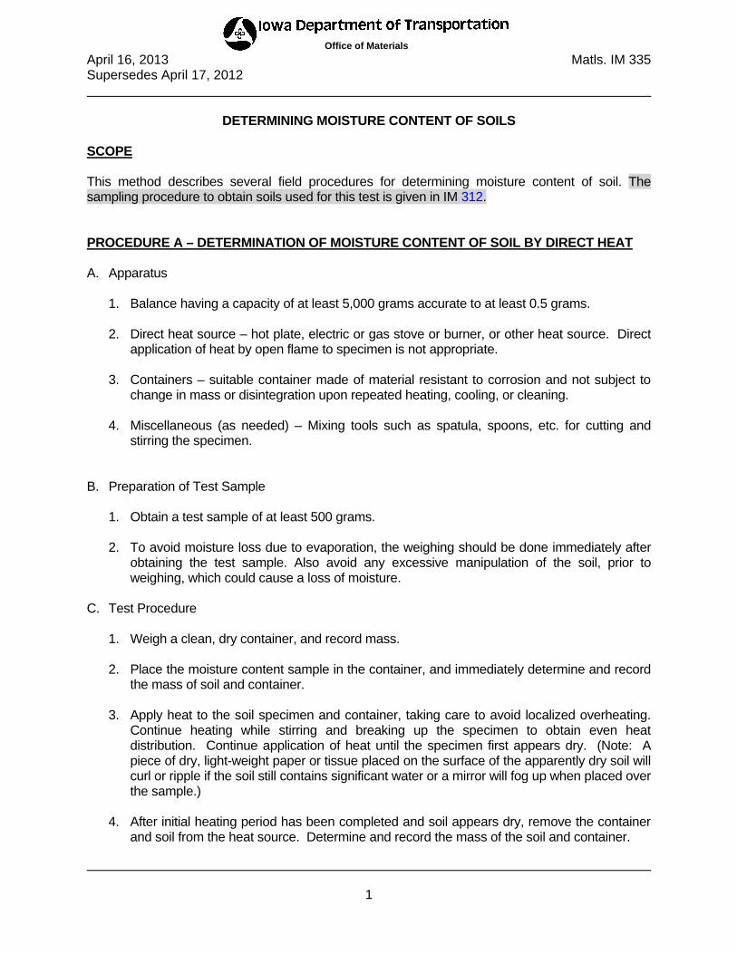
DETERMINING MOISTURE CONTENT OF SOILS SCOPE This method describes several field procedures for determining moisture content of soil. The sampling procedure to obtain soils used for this test is given in IM 312. PROCEDURE A – DETERMINATION OF MOISTURE CONTENT OF SOIL BY DIRECT HEAT A. Apparatus
1. Balance having a capacity of at least 5,000 grams accurate to at least 0.5 grams. 2. Direct heat source – hot plate, electric or gas stove or burner, or other heat source. Direct
application of heat by open flame to specimen is not appropriate. 3. Containers – suitable container made of material resistant to corrosion and not subject to
change in mass or disintegration upon repeated heating, cooling, or cleaning. 4. Miscellaneous (as needed) – Mixing tools such as spatula, spoons, etc. for cutting and
stirring the specimen.
B. Preparation of Test Sample
1. Obtain a test sample of at least 500 grams. 2. To avoid moisture loss due to evaporation, the weighing should be done immediately after
obtaining the test sample. Also avoid any excessive manipulation of the soil, prior to weighing, which could cause a loss of moisture.
C. Test Procedure
1. Weigh a clean, dry container, and record mass.
2. Place the moisture content sample in the container, and immediately determine and record the mass of soil and container.
3. Apply heat to the soil specimen and container, taking care to avoid localized overheating.
Continue heating while stirring and breaking up the specimen to obtain even heat distribution. Continue application of heat until the specimen first appears dry. (Note: A piece of dry, light-weight paper or tissue placed on the surface of the apparently dry soil will curl or ripple if the soil still contains significant water or a mirror will fog up when placed over the sample.)
4. After initial heating period has been completed and soil appears dry, remove the container
and soil from the heat source. Determine and record the mass of the soil and container.
April 16, 2013 Matls. IM 335 Supersedes April 17, 2012
2
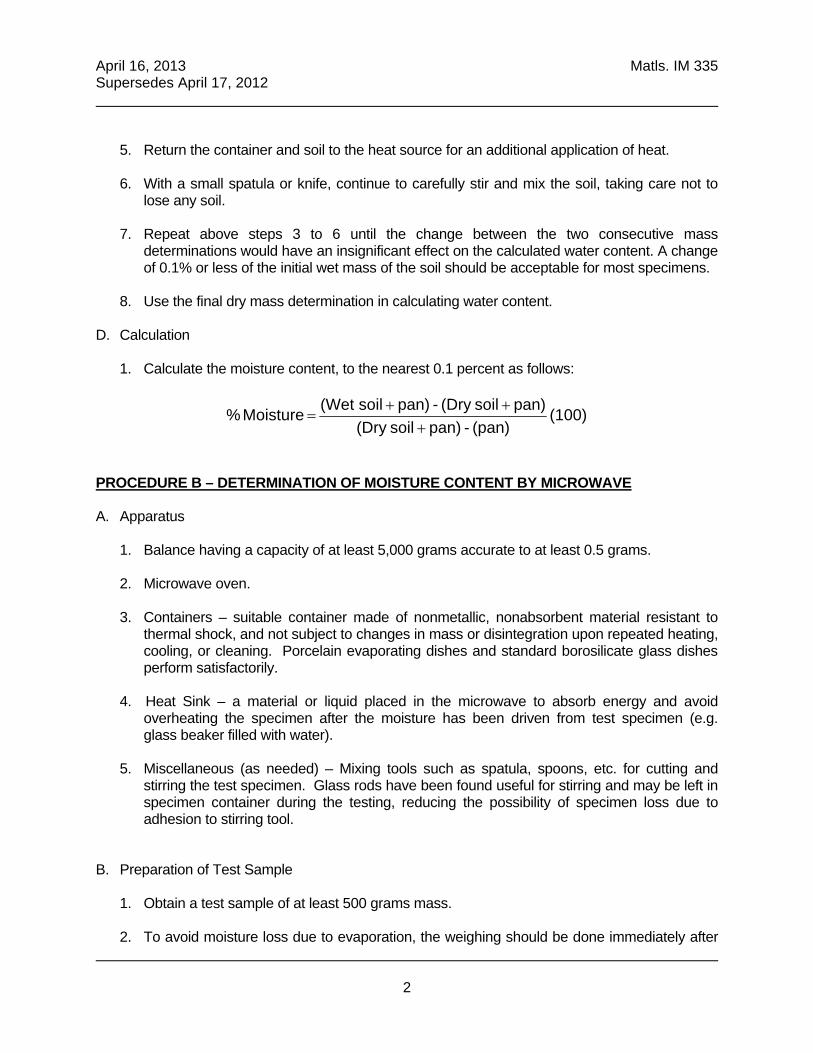
5. Return the container and soil to the heat source for an additional application of heat.
6. With a small spatula or knife, continue to carefully stir and mix the soil, taking care not to
lose any soil.
7. Repeat above steps 3 to 6 until the change between the two consecutive mass determinations would have an insignificant effect on the calculated water content. A change of 0.1% or less of the initial wet mass of the soil should be acceptable for most specimens.
8. Use the final dry mass determination in calculating water content.
D. Calculation
1. Calculate the moisture content, to the nearest 0.1 percent as follows:
(100) (pan) - pan) soil(Dry
pan) soil(Dry - pan) soil (Wet Moisture %
PROCEDURE B – DETERMINATION OF MOISTURE CONTENT BY MICROWAVE A. Apparatus
1. Balance having a capacity of at least 5,000 grams accurate to at least 0.5 grams. 2. Microwave oven. 3. Containers – suitable container made of nonmetallic, nonabsorbent material resistant to
thermal shock, and not subject to changes in mass or disintegration upon repeated heating, cooling, or cleaning. Porcelain evaporating dishes and standard borosilicate glass dishes perform satisfactorily.
4. Heat Sink – a material or liquid placed in the microwave to absorb energy and avoid
overheating the specimen after the moisture has been driven from test specimen (e.g. glass beaker filled with water).
5. Miscellaneous (as needed) – Mixing tools such as spatula, spoons, etc. for cutting and
stirring the test specimen. Glass rods have been found useful for stirring and may be left in specimen container during the testing, reducing the possibility of specimen loss due to adhesion to stirring tool.
B. Preparation of Test Sample
1. Obtain a test sample of at least 500 grams mass. 2. To avoid moisture loss due to evaporation, the weighing should be done immediately after

April 16, 2013 Matls. IM 335 Supersedes April 17, 2012
3
obtaining the test sample. Also avoid any excessive manipulation of the soil, prior to weighing, which could cause a loss of moisture.
C. Test Procedure
1. Weigh a clean, dry container, and record mass.
2. Place the moisture content sample in the container, and immediately determine and record the mass of soil and container.
3. Place the soil and container in a microwave oven with the heat sink and turn the oven on
for 3 minutes. If experience with a particular soil type, specimen size, or microwave oven indicates shorter or longer initial drying times can be used without overheating, the initial and subsequent drying times may be adjusted.
4. After the set time has elapsed, remove the container and soil from the microwave oven. Determine and record the mass of the soil and container.
5. With a small spatula or knife or glass rod, carefully stir and mix the soil, taking care not to
lose any soil.
6. Return the container and soil to the microwave oven and reheat for 1 minute.
7. Repeat above steps 4 to 6 until the change between the two consecutive mass determinations would have an insignificant effect on the calculated water content. A change of 0.1% or less of the initial wet mass of the soil should be acceptable for most specimens.
8. Use the final dry mass determination in calculating water content
D. Calculation
1. Calculate the moisture content, to the nearest 0.1 percent as follows:
(100) (pan) - pan) soil(Dry
pan) soil(Dry - pan) soil (Wet Moisture %

April 16, 2013 Matls. IM 335 Supersedes April 17, 2012
4
PROCEDURE C – DETERMINATION OF MOISTURE CONTENT BY DRYING OVEN A. Apparatus
1. Balance having a capacity of at least 5,000 grams accurate to at least 0.5 grams 2. Drying oven – thermostatically controlled, capable of being heated continuously at a
temperature of 230°F ± 9°F (110 °C ± 5°C). 3. Containers – suitable container made of material resistant to corrosion, and not subject to
change in mass or disintegration upon repeated heating, cooling, or cleaning. B. Preparation of Test Sample
1. Obtain a test sample of at least 500 grams. 2. To avoid moisture loss due to evaporation the weighing should be done immediately after
obtaining the test sample. Also avoid any excessive manipulation of the soil, prior to weighing, which could cause a loss of moisture.
C. Test Procedure
1. Weigh a clean, dry container, and record mass.
2. Place the moisture content sample in the container, and immediately determine and record the mass of soil and container.
3. Place the soil and container in a drying oven overnight (at least 16 hours).
4. Remove the container and soil from the oven. Determine and record the mass of the soil
and container.
5. Use the final dry mass determination in calculating water content.
D. Calculation
1. Calculate the moisture content, to the nearest 0.1 percent as follows:
(100) (pan) - pan) soil(Dry
pan) soil(Dry - pan) soil (Wet Moisture %

IM
540
Q
MA
– E
C

April 15, 2014 Matls. IM 540 New Issue
1
****THIS IS A NEW IM. – PLEASE READ CAREFULLY.****
QUALITY MANAGEMENT & ACCEPTANCE -
EMBANKMENT CONSTRUCTION GENERAL This IM describes the Quality Control Program (Embankment Construction) and quality assurance procedures for soils used in embankment construction that require moisture control or moisture and density control. SAMPLING The Contractor shall sample the soil per Materials IM 312. TESTING The Contractor shall use test procedures per Materials IM 204, Appendix A. A. Proctor
The Contractor shall determine optimum moisture content and maximum density by Proctor testing for each type of excavated or mixed soil which varies as to change the expected AASHTO classification, or if directed by the Engineer. With Engineer’s approval, and for soils that can be identified during excavation, the Contractor may use the optimum moisture content and maximum density as shown on the soils 'Q' sheets in the contract documents. In lieu of using values from the 'Q' sheets, the Contractor may choose to determine optimum moisture and maximum density from a field sample.
If the Engineer deems the optimum moisture and maximum density of material being excavated and/or mixed is not represented by that shown on the 'Q' sheets, the Contractor shall determine optimum moisture and maximum density from a field sample. When determined from a field sample at the option of the Contractor or at the Engineer’s request, the optimum moisture and maximum density values from the field sample prevail over that shown on the 'Q' sheets.
B. Moisture Content and Density
The Contractor shall test and verify that moisture content of material placed is within optimum moisture content range and if required, greater than or equal to required minimum density. Upper and lower control limits for field moisture content of embankment material will be shown in the contract documents.
C. Frequency.
April 15, 2014 Matls. IM 540 New Issue
2
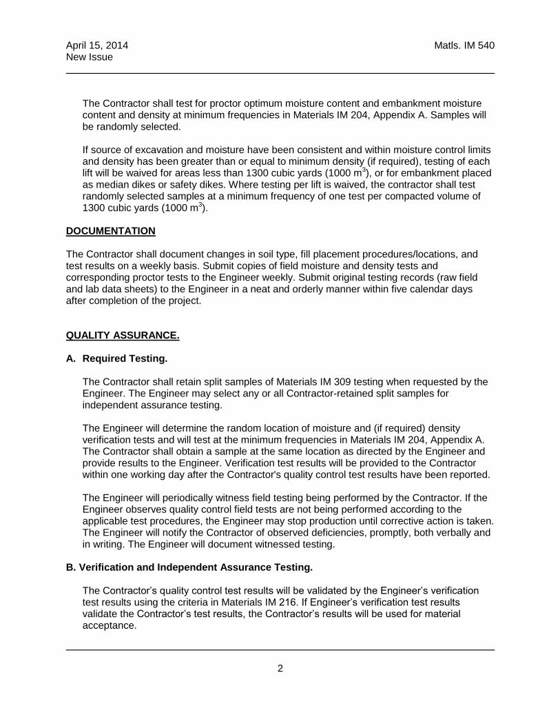
The Contractor shall test for proctor optimum moisture content and embankment moisture content and density at minimum frequencies in Materials IM 204, Appendix A. Samples will be randomly selected. If source of excavation and moisture have been consistent and within moisture control limits and density has been greater than or equal to minimum density (if required), testing of each lift will be waived for areas less than 1300 cubic yards (1000 m3), or for embankment placed as median dikes or safety dikes. Where testing per lift is waived, the contractor shall test randomly selected samples at a minimum frequency of one test per compacted volume of 1300 cubic yards (1000 m3).
DOCUMENTATION
The Contractor shall document changes in soil type, fill placement procedures/locations, and test results on a weekly basis. Submit copies of field moisture and density tests and corresponding proctor tests to the Engineer weekly. Submit original testing records (raw field and lab data sheets) to the Engineer in a neat and orderly manner within five calendar days after completion of the project.
QUALITY ASSURANCE.
A. Required Testing.
The Contractor shall retain split samples of Materials IM 309 testing when requested by the Engineer. The Engineer may select any or all Contractor-retained split samples for independent assurance testing. The Engineer will determine the random location of moisture and (if required) density verification tests and will test at the minimum frequencies in Materials IM 204, Appendix A. The Contractor shall obtain a sample at the same location as directed by the Engineer and provide results to the Engineer. Verification test results will be provided to the Contractor within one working day after the Contractor's quality control test results have been reported. The Engineer will periodically witness field testing being performed by the Contractor. If the Engineer observes quality control field tests are not being performed according to the applicable test procedures, the Engineer may stop production until corrective action is taken. The Engineer will notify the Contractor of observed deficiencies, promptly, both verbally and in writing. The Engineer will document witnessed testing.
B. Verification and Independent Assurance Testing.
The Contractor’s quality control test results will be validated by the Engineer’s verification test results using the criteria in Materials IM 216. If Engineer’s verification test results validate the Contractor’s test results, the Contractor’s results will be used for material acceptance.
April 15, 2014 Matls. IM 540 New Issue
3
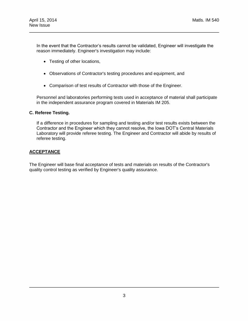
In the event that the Contractor’s results cannot be validated, Engineer will investigate the reason immediately. Engineer's investigation may include:
Testing of other locations,
Observations of Contractor's testing procedures and equipment, and
Comparison of test results of Contractor with those of the Engineer.
Personnel and laboratories performing tests used in acceptance of material shall participate in the independent assurance program covered in Materials IM 205.
C. Referee Testing.
If a difference in procedures for sampling and testing and/or test results exists between the Contractor and the Engineer which they cannot resolve, the Iowa DOT’s Central Materials Laboratory will provide referee testing. The Engineer and Contractor will abide by results of referee testing.
ACCEPTANCE
The Engineer will base final acceptance of tests and materials on results of the Contractor's quality control testing as verified by Engineer's quality assurance.

OTH
ER IM
’S


Other IM’s
I. IM 204 Appendix A – Roadway & Borrow Excavation & Embankments
II. IM 208 – Materials Laboratory Qualification Program (pages with soils items)
III. IM 213 Appendix D – Soils Technician Duties
IV. IM 216 – Guidelines for Determining the Acceptability of Test Results
V. IM 326 – Determining the Density of Undisturbed Soil Cores by Displacement
VI. IM 334 – Determining Moisture Content & Density of Soils, Bases & Subbases with a Nuclear
Gauge


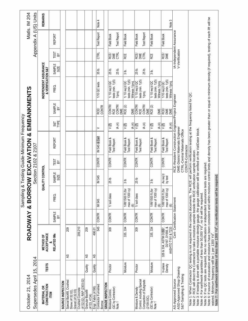
IM 204
Appendix A

Sa
mp
ling
& T
esting
Gu
ide
-Min
imu
m F
req
uen
cy
Octo
ber
21, 2
01
4
RO
AD
WA
Y &
BO
RR
OW
EX
CA
VA
TIO
N &
EM
BA
NK
ME
NT
S
Ma
tls.
IM 2
04
Su
pe
rse
de
s A
pril 1
5, 2
01
4
Se
ction
21
02 &
210
7
Ap
pe
nd
ix A
(U
S)
Un
its
M
AT
ER
IAL
OR
C
ON
ST
RU
CT
ION
IT
EM
T
ES
TS
M
ET
HO
D O
F
AC
CE
PT
AN
CE
&
R
EL
AT
ED
IMs
Q
UA
LIT
Y C
ON
TR
OL
IND
EP
EN
DE
NT
AS
SU
RA
NC
E
& V
ER
IFIC
AT
ION
S&
T
R
EM
AR
KS
S
AM
PLE
B
Y
F
RE
Q.
S
AM
PLE
S
IZE
T
ES
T
BY
R
EP
OR
T
S
&T
T
YP
E
S
AM
PLE
B
Y
F
RE
Q.
S
AM
PLE
S
IZE
T
ES
T
BY
R
EP
OR
T
SO
UR
CE
INS
PE
CT
ION
Spe
cial
Bac
kfill
, Cru
shed
S
tone
(41
32.0
2),
Gra
vel (
4132
.03)
A
S
209
Cru
shed
Con
cret
e (4
132.
02),
RA
P (
2303
.02)
209,
210
Gra
nula
r B
ackf
ill
(413
3, 4
134)
Q
ualit
y A
S
209
Eng
r. F
abric
(41
96)
Qua
lity
AS
49
6.01
Con
trac
tor
Fur
nish
ed
Bor
row
545
CO
NT
R
IM 5
45
IM 5
45
CO
NT
R
IM 5
45 &
Cer
t V
R
CE
/ C
ON
TR
1/
10 Q
C te
sts
35 lb
.
CT
RL
Tes
t Rep
ort
Not
e 4
GR
AD
E IN
SP
EC
TIO
N
Moi
stur
e C
ontr
ol,
(QC
by
Con
trac
tor)
N
ote
1
Pro
ctor
30
9 C
ON
TR
1/
soi
l cla
ss
25 lb
C
ON
TR
F
ield
Boo
k &
T
est R
epor
t V
(7)
IA
(4)
CO
NT
R/
RC
E
CO
NT
R/
DM
E
1/ 1
0 re
q’d
QC
te
sts
(min
. 1)(
5)
1/pr
oj.
25 lb
. 25
lb.
RC
E/
DM
E
CT
RL
Fie
ld B
ook
Tes
t Rep
ort
Moi
stur
e
335,
334
C
ON
TR
1/
lift/1
500
ft (f
or
max
of 1
300
cy)
(6)
3 lb
C
ON
TR
F
ield
Boo
k &
T
est R
epor
t V
(7)
IA
(4)
RC
E (
2)
DM
E
1/ 1
0 re
q’d
QC
te
sts
(min
. 1)(
5)
Witn
ess
1/pr
oj.
3 lb
. R
CE
F
ield
Boo
k
Moi
stur
e &
Den
sity
C
ontr
ol, i
nclu
ding
Spe
cial
C
ompa
ctio
n of
Sub
grad
e (2
109.
03C
),
(QC
by
Con
trac
tor)
N
ote
1
Pro
ctor
30
9 C
ON
TR
1/
soi
l cla
ss
25 lb
C
ON
TR
F
ield
Boo
k &
T
est R
epor
t V
(7)
IA
(4)
CO
NT
R/
RC
E
CO
NT
R/
DM
E
1/ 1
0 re
q’d
QC
te
sts
(min
. 1)(
5)
1/pr
oj.
25 lb
. 25
lb.
RC
E/
DM
E
CT
RL
Fie
ld B
ook
Tes
t Rep
ort
Moi
stur
e
335,
334
C
ON
TR
1/
lift/1
500
ft.(f
or
max
of 1
300
cy)
(6)
3 lb
C
ON
TR
F
ield
Boo
k &
T
est R
epor
t V
(7)
IA
(4)
RC
E (
2)
DM
E
1/ 1
0 re
q’d
QC
te
sts
(min
. 1)(
5)
Witn
ess
1/pr
oj.
3 lb
. R
CE
F
ield
Boo
k
In-p
lace
D
ensi
ty
326
& 3
34, A
ST
M D
2937
, D
2167
, D15
56, &
A
AS
HT
O T
191
& T
233
CO
NT
R
1/lif
t/150
0 ft
(for
m
ax o
f 130
0 cy
) (6
)
As
req’
d by
test
C
ON
TR
F
ield
Boo
k &
T
est R
epor
t V
(7)
IA
(4)
RC
E/
DM
E
DM
E
1/10
req
’d Q
C
test
s (m
in. 1
)(5)
W
itnes
s 1/
proj
.
R
CE
/ D
ME
F
ield
Boo
k N
ote
3
AS
-Appro
ved S
ourc
e
Cert
- C
ert
ific
atio
n S
tate
ment
RC
E-R
esid
ent
Constr
uctio
n E
ngin
eer/
Pro
ject E
ngin
eer
IA-I
ndependent A
ssura
nce
AS
D-A
ppro
ved S
hop D
raw
ing
DM
E-D
istr
ict
Mate
ria
ls E
ngin
eer
V-V
erificatio
n
S&
T-S
am
plin
g &
Testin
g
C
TR
L-C
entr
al M
ate
ria
ls O
ffic
e
CO
NT
R-C
ontr
acto
r
Note
1: W
hen C
ontr
acto
r Q
C t
esting is n
ot
required in t
he c
onta
ct
docum
ents
. T
he R
CE
will
perf
orm
verificatio
n testin
g a
t th
e f
requency lis
ted for
QC
. N
ote
2: R
CE
will
direct th
e C
ontr
acto
r to
take a
mois
ture
sam
ple
besid
e t
he R
CE
verificatio
n s
am
ple
lo
catio
n.
Note
3: If t
estin
g is d
one w
ith a
port
able
mois
ture
-density g
auge, th
e g
auge c
alib
ratio
n w
ill b
e v
erifie
d o
n t
he V
aliD
ato
r blo
ck.
Note
4: F
or
eart
hw
ork
quantitie
s o
f le
ss than 5
0,0
00 Y
d3, no IA
will
be r
equired.
Note
5: If n
o Q
C t
ests
are
required,
then n
o v
erificatio
n o
r in
dependent
assura
nce t
ests
are
required.
Note
6: If s
ourc
e o
f excavatio
n a
nd m
ois
ture
have b
een c
onsis
tent and w
ithin
mois
ture
contr
ol lim
its a
nd d
ensity h
as b
een g
reate
r th
an o
r equal to
min
imum
density (
if r
equired),
testin
g o
f each lift
will
be
waiv
ed.
Min
imum
fre
quency w
ill b
e 1
per
1300 Y
d3.
Note
7: F
or
eart
hw
ork
quantities o
f le
ss t
han 1
300 Y
d3, no v
erification t
ests
will
be r
equired.


IM 208


April 16, 2013 Matls. IM 208 Supersedes October 19, 2010
1
Office of Materials
MATERIALS LABORATORY QUALIFICATION PROGRAM GENERAL The FHWA has outlined a Laboratory Qualification Program in the Federal-Aid Policy Guide update published as 23 CFR 637 on June 29, 1995. The updated guide has requirements for laboratories performing testing on Federal-Aid highway projects. In order to avoid an appearance of a conflict of interest, any qualified non-DOT laboratory shall perform only one of the following types of testing on the same project: Verification testing, quality control testing, IA testing, or dispute resolution testing. LABORATORIES TO BE QUALIFIED The following laboratories are included in the qualification program for all Federal-Aid projects: Central Materials Laboratory Ready Mix Laboratories 6 District Laboratories PCC Contractor Laboratories District Area Laboratories HMA Contractor Laboratories Resident Construction Laboratories* Consultant and Commercial Laboratories * Aggregate Producer Laboratories City and County Laboratories * Soils Field Laboratories* * May be qualified at the time of a project. LABORATORY QUALIFICATION PROCESS A two-level qualification system is required by the FHWA. Laboratories are either accredited or qualified. The accreditation process is more rigorous than the qualification process. Accredited Laboratory Process The Central Materials Laboratory and the six District Laboratories will be accredited as outlined in the 23 CFR 637 guide. The Central Materials Laboratory is accredited through the AASHTO Materials Reference Laboratory Program. The District Materials Laboratories will be accredited by using the Central Materials Staff and equipment to check testing and testing procedures and by using the same calibration and training documentation process. Laboratories will be accredited for a two-year period. In addition, an annual review will be made by the Central Office Staff. Appendix A contains the procedures for accrediting the District Materials Laboratories.

April 16, 2013 Matls. IM 208 Supersedes October 19, 2010
2
Qualified Laboratory Process The remaining laboratories will be qualified as outlined below: The District Materials Offices will qualify laboratories. Laboratories will be qualified for a two-year period. In addition, an annual review will be made by District Staff. Appendix B contains the procedures for qualifying materials laboratories. Four laboratory types will be qualified, aggregate laboratories, PC Concrete laboratories, soils field laboratories, and Hot Mix Asphalt laboratories. Qualified laboratories will have the following: 1. Current manuals and test methods to perform the qualified testing available 2. A technician certified by the Iowa DOT to perform the qualified testing 3. Proper equipment to perform the qualified testing (calibrated or checked annually according
to Appendix B) 4. Satisfactory project and proficiency test results 5. Documentation of equipment calibrations, equipment checks, and proficiency results The District may elect to accept qualifications, accreditations, or inspections from other government agencies or Laboratory inspection agencies. The AASHTO Materials Reference Laboratory (AMRL) and Cement and Concrete Reference Laboratory are 2 common Laboratory inspection programs. The links are: http://www.amrl.net/amrlsitefinity/default/aap/r18labs.aspx http://www.ccrl.us/Lip/LabListReport.pdf ADMINISTRATION OF THE PROCESS The Central Materials Laboratory will be responsible for implementation and operation of the Laboratory Qualification Program. The Central Materials Laboratory will accredit the District Laboratories. The District Materials Offices will qualify laboratories. NON-COMPLIANCE/DISPUTE RESOLUTION A laboratory that does not meet the requirements of the IM is subject to elimination from the qualification program. Disputes concerning calibration and correlation of equipment will be resolved by the office responsible for the qualification. For disputes that cannot be resolved at the District, the Central Materials Laboratory will be the final authority.

April 17, 2014 Matls. IM 208 Supersedes October 16, 2012 Appendix B
1
LABORATORY QUALIFICATION PROGRAM The District Materials Office will qualify the other laboratories and maintain records of the qualification for three years. The District Staff will check the following prior to qualifying a laboratory: 1. Establish the type of laboratory (Aggregate, Hot Mix Asphalt, Soils Field, PC Concrete). 2. Check for current manuals and test procedures covering the qualified testing. 3. Check the certification of the testing personnel. 4. Document that proper equipment is available to perform qualified testing. 5. Check documentation system. Scheduling of the qualification review will be discussed with the laboratories seeking qualification. The District staff performing the qualification review should have the appropriate certification (IM 213) for the type of laboratory and tests being reviewed. The District Materials Engineer should be contacted for laboratories that have been qualified in other states. The District Materials Office may qualify a laboratory based on an acceptable qualification report and qualification program from another state transportation agency. Table 1 and the pages following cover the list of items to be reviewed. An oral close out on any deficiencies will be held with the testing personnel. Written notice will be sent within two weeks of the inspection. District personnel will re-inspect after correction of any deficiencies. A form showing the laboratory type, the date qualified, and the expiration date will be issued by the District Materials Engineer. The list of Qualified Laboratories will be maintained on a database accessible by authorized Materials Personnel. NON-COMPLIANCE/DISPUTE RESOLUTION A laboratory that does not meet the requirements of the IM is subject to elimination from the qualification program. The office responsible for the qualification will resolve disputes concerning calibration and correlation of equipment. For disputes that cannot be resolved at the District level, the Central Materials Laboratory will be the final authority.
Table 1 - Laboratory Qualification Checklist √ Calib./Verif.
Interval Calib./Verif. Procedure
Tester Qualifications-Proper Iowa DOT certifications
Current Test Procedures
Current Calibration Procedures & Records

April 17, 2014 Matls. IM 208 Supersedes October 16, 2012 Appendix B
2
Documentation of correlation results and corrective actions taken for previous construction season.
Soils Field Laboratory
Balances 12 months Iowa 917
Sieves- wear, tear, size 12 months
Mold, Base, and rammer condition (a) IM 309
Aggregate Laboratory
Balances 12 months Iowa 917
Sieves- wear, tear, size, and opening size 12 months Iowa 1506
Splitter- condition 12 months (Visual)
Mechanical Shakers- condition (if used) 12 months Iowa 1502
HMA Laboratory
Balances- and water bath 12 months Iowa 917
Sieves- wear, tear, size, and opening size 12 months Iowa 1506
Splitter- condition 12 months (Visual)
Mechanical Shakers- condition (if used) 12 months Iowa 1502
Rice equipment- vacuum and flask 12 months IM 350
Thermometers 12 months Iowa 1607
Ovens- temperatures 12 months Iowa 1501
Gyratory Compactor and molds 12 months Iowa 1522
PCC Laboratory
Balances 12 months Iowa 917
Sieves- wear, tear, size, and opening size 12 months Iowa 1506
Splitter- condition 12 months (Visual)
Mechanical Shakers- condition (if used) 12 months Iowa 1502
Air Meter 12 months IM 318
Slump Cone and equipment-condition 12 months
Flexural Strength Apparatus 12 months Central Lab
(a) The mold, base or rammer should be checked if the condition warrants.
LABORATORY ITEMS PCC Portable Paving Plant The following list contains, as a minimum, what is required for a qualified PCC paving plant laboratory. The test equipment to perform each of the required tests is contained in the respective IM.
Field Lab of suitable size for workspace, space to perform tests, and sample storage. Locate the Field Lab so it is convenient to the plant, but outside the influence of plant vibration.
Air-conditioned Personal computer

April 17, 2014 Matls. IM 208 Supersedes October 16, 2012 Appendix B
8
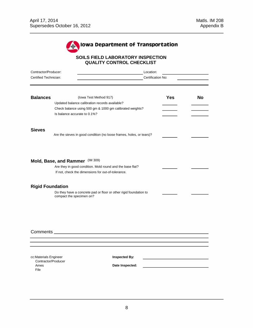
Contractor/Producer: Location:
Certified Technician: Certification No:
Balances (Iowa Test Method 917) Yes No Updated balance calibration records available?
Check balance using 500 gm & 1000 gm calibrated weights?
Is balance accurate to 0.1%?
Sieves Are the sieves in good condition (no loose frames, holes, or tears)?
Mold, Base, and Rammer Are they in good condition. Mold round and the base flat?
If not, check the dimensions for out-of-tolerance.
Rigid Foundation
Do they have a concrete pad or floor or other rigid foundation to compact the specimen on?
Comments:
cc:Materials Engineer Inspected By: Contractor/Producer Ames Date Inspected: File
SOILS FIELD LABORATORY INSPECTION QUALITY CONTROL CHECKLIST
(IM 309)


IM 213
Appendix D

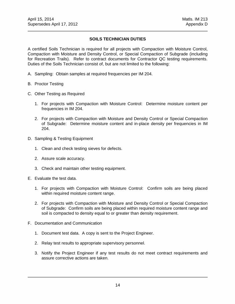
April 15, 2014 Matls. IM 213
Supersedes April 17, 2012 Appendix D
14
SOILS TECHNICIAN DUTIES
A certified Soils Technician is required for all projects with Compaction with Moisture Control,
Compaction with Moisture and Density Control, or Special Compaction of Subgrade (including
for Recreation Trails). Refer to contract documents for Contractor QC testing requirements.
Duties of the Soils Technician consist of, but are not limited to the following:
A. Sampling: Obtain samples at required frequencies per IM 204.
B. Proctor Testing
C. Other Testing as Required
1. For projects with Compaction with Moisture Control: Determine moisture content per
frequencies in IM 204.
2. For projects with Compaction with Moisture and Density Control or Special Compaction
of Subgrade: Determine moisture content and in-place density per frequencies in IM
204.
D. Sampling & Testing Equipment
1. Clean and check testing sieves for defects.
2. Assure scale accuracy.
3. Check and maintain other testing equipment.
E. Evaluate the test data.
1. For projects with Compaction with Moisture Control: Confirm soils are being placed
within required moisture content range.
2. For projects with Compaction with Moisture and Density Control or Special Compaction
of Subgrade: Confirm soils are being placed within required moisture content range and
soil is compacted to density equal to or greater than density requirement.
F. Documentation and Communication
1. Document test data. A copy is sent to the Project Engineer.
2. Relay test results to appropriate supervisory personnel.
3. Notify the Project Engineer if any test results do not meet contract requirements and
assure corrective actions are taken.


IM 216

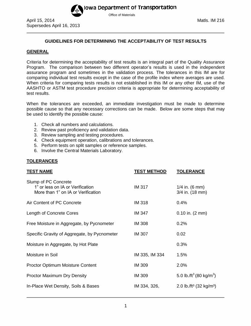
April 15, 2014 Matls. IM 216 Supersedes April 16, 2013
1
Office of Materials
GUIDELINES FOR DETERMINING THE ACCEPTABILITY OF TEST RESULTS GENERAL Criteria for determining the acceptability of test results is an integral part of the Quality Assurance Program. The comparison between two different operator’s results is used in the independent assurance program and sometimes in the validation process. The tolerances in this IM are for comparing individual test results except in the case of the profile index where averages are used. When criteria for comparing tests results is not established in this IM or any other IM, use of the AASHTO or ASTM test procedure precision criteria is appropriate for determining acceptability of test results. When the tolerances are exceeded, an immediate investigation must be made to determine possible cause so that any necessary corrections can be made. Below are some steps that may be used to identify the possible cause:
1. Check all numbers and calculations. 2. Review past proficiency and validation data. 3. Review sampling and testing procedures. 4. Check equipment operation, calibrations and tolerances. 5. Perform tests on split samples or reference samples. 6. Involve the Central Materials Laboratory.
TOLERANCES TEST NAME TEST METHOD TOLERANCE Slump of PC Concrete 1” or less on IA or Verification IM 317 1/4 in. (6 mm) More than 1” on IA or Verification 3/4 in. (18 mm) Air Content of PC Concrete IM 318 0.4% Length of Concrete Cores IM 347 0.10 in. (2 mm) Free Moisture in Aggregate, by Pycnometer IM 308 0.2% Specific Gravity of Aggregate, by Pycnometer IM 307 0.02 Moisture in Aggregate, by Hot Plate 0.3% Moisture in Soil IM 335, IM 334 1.5% Proctor Optimum Moisture Content IM 309 2.0% Proctor Maximum Dry Density IM 309 5.0 lb./ft3 (80 kg/m3) In-Place Wet Density, Soils & Bases IM 334, 326, 2.0 lb./ft³ (32 kg/m³)
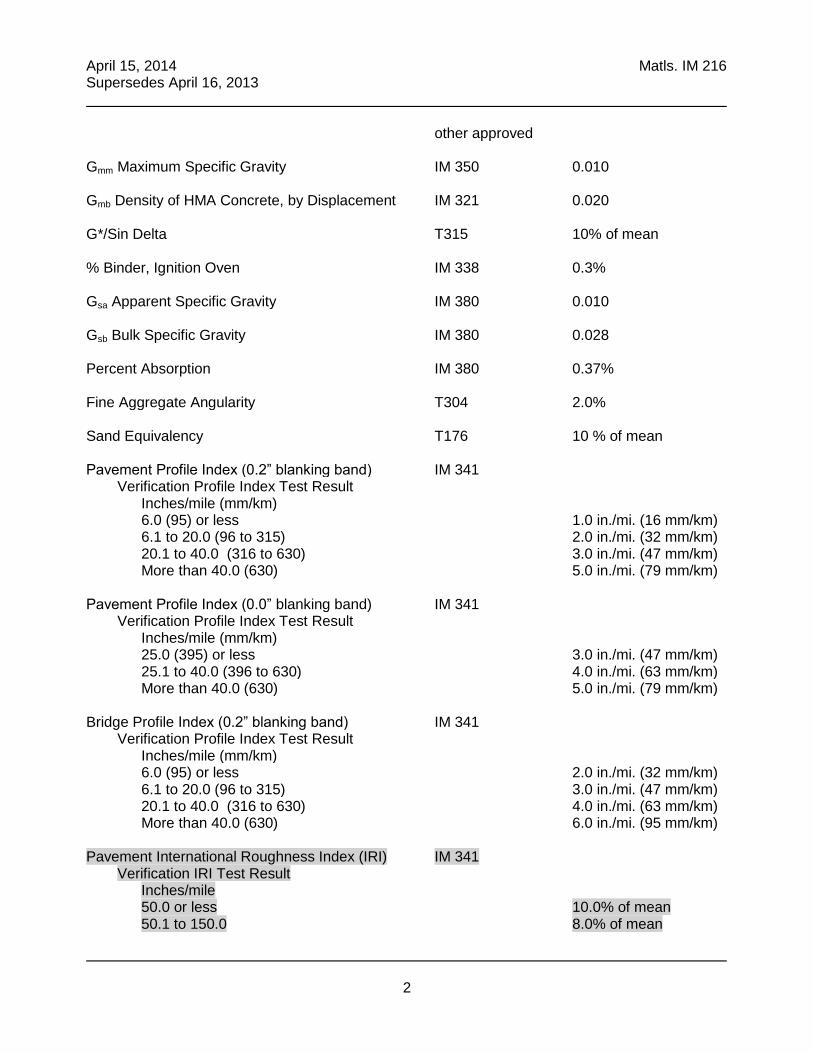
April 15, 2014 Matls. IM 216 Supersedes April 16, 2013
2
other approved Gmm Maximum Specific Gravity IM 350 0.010 Gmb Density of HMA Concrete, by Displacement IM 321 0.020 G*/Sin Delta T315 10% of mean % Binder, Ignition Oven IM 338 0.3% Gsa Apparent Specific Gravity IM 380 0.010 Gsb Bulk Specific Gravity IM 380 0.028 Percent Absorption IM 380 0.37% Fine Aggregate Angularity T304 2.0% Sand Equivalency T176 10 % of mean Pavement Profile Index (0.2” blanking band) IM 341 Verification Profile Index Test Result Inches/mile (mm/km) 6.0 (95) or less 1.0 in./mi. (16 mm/km) 6.1 to 20.0 (96 to 315) 2.0 in./mi. (32 mm/km) 20.1 to 40.0 (316 to 630) 3.0 in./mi. (47 mm/km) More than 40.0 (630) 5.0 in./mi. (79 mm/km) Pavement Profile Index (0.0” blanking band) IM 341 Verification Profile Index Test Result Inches/mile (mm/km) 25.0 (395) or less 3.0 in./mi. (47 mm/km) 25.1 to 40.0 (396 to 630) 4.0 in./mi. (63 mm/km) More than 40.0 (630) 5.0 in./mi. (79 mm/km) Bridge Profile Index (0.2” blanking band) IM 341 Verification Profile Index Test Result Inches/mile (mm/km) 6.0 (95) or less 2.0 in./mi. (32 mm/km) 6.1 to 20.0 (96 to 315) 3.0 in./mi. (47 mm/km) 20.1 to 40.0 (316 to 630) 4.0 in./mi. (63 mm/km) More than 40.0 (630) 6.0 in./mi. (95 mm/km) Pavement International Roughness Index (IRI) IM 341 Verification IRI Test Result Inches/mile 50.0 or less 10.0% of mean 50.1 to 150.0 8.0% of mean

IM 326


October 19, 2004 Matls. IM 326
Supersedes April 20, 2004
1
Office of Materials
DETERMINING THE DENSITY OF UNDISTURBED
SOIL CORES BY DISPLACEMENT
SCOPE
This method of test is intended to determine the density of cohesive soils in the natural state or
after compaction by measuring the weight, volume and moisture content of the undisturbed
sample. This test method is the field procedure for Laboratory Test Method 102.
PROCEDURE
A. Apparatus
1. Core sampling device consisting of a bit, bit head, rod, driving head and driver
2. Balance accurate to 0.5 gram
3. Graduate, 500 ml
4. 1 gallon (4 liter) can
5. Supply of liquid. May be either kerosene or No. 2 diesel fuel.
6. Volume-measuring device, consisting of a 9 1/2 in. high by 5 1/2 in. (241.3 mm x 139.7
mm) diameter brass tube and a 9 1/2 in. by 2 in. (241.3 mm x 50.8 mm) diameter brass
tube connected near their base by a 1 in. (25.4 mm) diameter cross tube. The 20 in. (50.8
mm) diameter tube acting as a surge tank has an anti-siphoning overflow outlet near its
top.
7. Core carrier
8. Trimming knife
9. Waxed paper or cellophane
10. Extruding pedestal
11. Suitable containers for transporting the sample
12. Stove or other suitable device for drying sample
B. Sample Procedure
1. Hold the sampling device in a vertical position and drive to the bottom of the lift of material
to be tested. Do not overdrive as this will compact and disturb the sample. During this
driving procedure exercise care to keep the four cap screws and the screwed joints on
each end of the rod tight to prevent damage to the threads.

October 19, 2004 Matls. IM 326
Supersedes April 20, 2004
2
2. Rotate the driving head in a circular motion to break the core loose. It can then be lifted
out easily.
3. After disconnecting the bit from the bit head, remove the core by pushing it on through the
top of the bit head using the extruding pedestal.
4. Wrap the sample in cellophane or waxed paper to maintain its moisture content until
tested.
5. Place the wrapped specimen with proper identification in a suitable container for
transporting.
C. Test Procedure
1. Trim the moisture test sample from the sides of the core leaving a representative sample
for the full depth of the lift of material to be tested. The moisture test sample obtained in
this manner should be of a size equal to between 3 and 4 grams per lineal millimeter of
core.
2. Immediately weigh the moisture test sample, dry to a constant mass (weight), and reweigh
the dried sample to determine the moisture content of the specimen.
3. Weigh the remainder of the core.
4. Place the core carrier in the volume-measuring device and fill with liquid until the overflow
is running freely. After the overflow cuts off, place the 500-ml. graduate (or larger
container if needed) under the outlet.
5. Remove the core carrier, place the core in it and carefully lower into a 1 gallon (4 liter) can
containing sufficient liquid to cover the specimen. Soak the core in liquid until the air
bubbles cease, indicating the filling of air voids. Remove the sample and allow the excess
liquid to drain from the sides of the specimen.
6. Carefully lower the core carrier and sample into the volume-measuring device. Do not
allow any liquid to run over the top of the device during this procedure.
7. Allow the displaced liquid to run into the 500-ml. graduate (or a larger container, if needed,
and then measure in the graduate) until it stops. The volume of this displaced liquid is the
volume of the sample.
8. Make certain that no portion of the samples extends above the level of the liquid at the
time the liquid stops flowing.
October 19, 2004 Matls. IM 326
Supersedes April 20, 2004
3
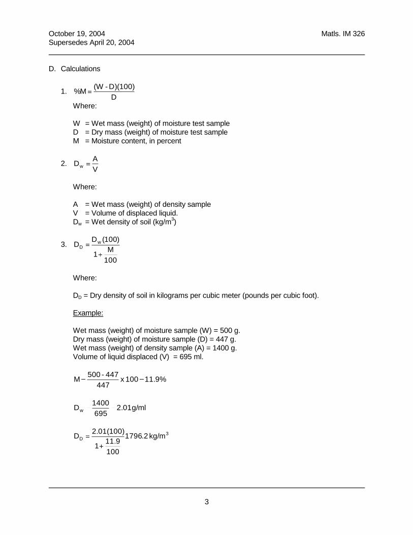
D. Calculations
1. D
D)(100)-(W M%
Where:
W = Wet mass (weight) of moisture test sample
D = Dry mass (weight) of moisture test sample
M = Moisture content, in percent
2. V
A Dw
Where:
A = Wet mass (weight) of density sample
V = Volume of displaced liquid.
Dw = Wet density of soil (kg/m3)
3.
100
M 1
)100(D D w
D
Where:
DD = Dry density of soil in kilograms per cubic meter (pounds per cubic foot).
Example:
Wet mass (weight) of moisture sample (W) = 500 g.
Dry mass (weight) of moisture sample (D) = 447 g.
Wet mass (weight) of density sample (A) = 1400 g.
Volume of liquid displaced (V) = 695 ml.
11.9% 100 x 447
447-500 M
g/ml 2.01 695
1400 Dw
3D kg/m 2.1796
100
11.9 1
2.01(100) D

October 19, 2004 Matls. IM 326
Supersedes April 20, 2004
4
Figure 1. Volume-measuring Device

IM 334

April 15, 2014 Matls. IM 334 Supersedes October 18, 2011
1
Office of Materials
DETERMINING MOISTURE CONTENT & DENSITY OF SOILS, BASES & SUBBASES WITH A NUCLEAR GAUGE
SCOPE This test method describes the procedure used in determining the in-place density and moisture content of soils, cold-in-place recycled asphalt pavement, soil aggregate sub-base, soil lime sub-base, and cement treated granular base or sub-base by the use of nuclear method. OPERATOR QUALIFICATION In addition to complying with IM 206, an operator, to determine the moisture content and density of soils, bases, and sub-bases with a nuclear gauge, must first demonstrate knowledge and proficiency in various related areas that may affect the test result. The specific areas will be determined by and demonstrated to the satisfaction of the District Materials Engineer or an authorized representative. PROCEDURE A. Apparatus
1. A recognized nuclear moisture-density gauge containing a radioisotope, detectors and
related circuitry. The gauge shall be capable of determining densities by either the backscatter or direct transmission methods.
2. A reference standard for the purpose of taking standard counts, and for checking
equipment operation. 3. A drill rod and combination guide-scraper plate for preparing the testing site.
4. Manufacturer Instructional Manual.
B. Standard Counts
1. Place the reference standard in a position recommended by the manufacturer to obtain standard counts.
2. Allow the gauge to warm up as suggested by the manufacturer.
3. Take one automatic four-minute standard count per manufacturer instructions. This count should be within 1% of the latest standard count established for the gauge. In the event the standard count varies by more than 1%, make a note of that number, reject that count on the gauge and then obtain another standard count. The two standard count numbers just obtained should be within 1% of each other and within 2% of the latest established standard count. If so, retain and record the last standard count taken.
4. If the day-to-day shift in the standard count varies more than 2% for moisture or 1% for
density, reset the gauge on the standard and repeat the procedure in B3.

April 15, 2014 Matls. IM 334 Supersedes October 18, 2011
2
5. Keep a log of the gauge standard counts. 6. Standard counts should be taken twice a day to detect any shift during daily use.
C. Site Preparation
1. Select a random location in the testing area. Test will be run at three locations at this station, the center and the ¼ points from each side of the center. Moisture and density determinations will be based on the average of the readings from the three locations. Test locations should be such that the gauge will be a least 6 in. (150 mm) away from any vertical projection. Be sure the vehicle is at least 10 ft. (3 m) away from the test site.
2. Remove all loose and disturbed material, and remove additional material as necessary to
reach the top of the compacted lift to be tested. 3. Prepare a horizontal area, sufficient in size to accommodate the gauge, using the scraper
plate supplied with the gauge; by planing to a smooth condition so as to obtain maximum contact between the gauge and material being tested. Make sure the gauge sits solidly on the site without rocking.
4. The maximum depressions beneath the gauge shall not exceed 1/8 in. (3 mm). Use native
fines or fine sand to fill voids and level the excess with the scraper plate. The total area thus filled with native fines or sand should not exceed ten percent of the bottom area of the gauge.
D. Moisture Determination
1. Prepare test site as described in C. 2. Obtain a one-minute moisture count. 3. The moisture measurement is based upon the thermalization of fast neutrons by hydrogen
atoms. Because some materials may contain hydrogen other than free water or may contain thermalizing elements other than hydrogen, not less than ten moisture samples should be oven dried to correct the calibration data. If the gauge reading is higher than the values obtained by oven dry samples, the error is due to hydrogen containing materials, and the correction may be made by subtracting a constant value from the gauge reading. If the gauge reading is lower than that obtained by oven drying, the error is likely due to materials which absorb thermalized neutrons. In this case, the error is not a constant offset, but varies directly with the moisture content. The compensation is made by adding the full error at moisture contents used to obtain the error data and reducing the added value at lower moisture contents. At zero moisture, the error would be zero.
April 15, 2014 Matls. IM 334 Supersedes October 18, 2011
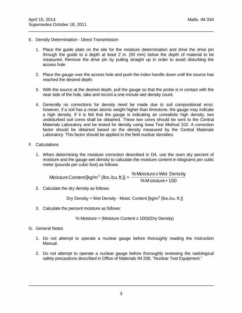
3
E. Density Determination - Direct Transmission 1. Place the guide plate on the site for the moisture determination and drive the drive pin
through the guide to a depth at least 2 in. (50 mm) below the depth of material to be measured. Remove the drive pin by pulling straight up in order to avoid disturbing the access hole.
2. Place the gauge over the access hole and push the index handle down until the source has
reached the desired depth. 3. With the source at the desired depth, pull the gauge so that the probe is in contact with the
near side of the hole, take and record a one-minute wet density count. 4. Generally no corrections for density need be made due to soil compositional error,
however, if a soil has a mean atomic weight higher than limestone, the gauge may indicate a high density. If it is felt that the gauge is indicating an unrealistic high density, two undisturbed soil cores shall be obtained. These two cores should be sent to the Central Materials Laboratory and be tested for density using Iowa Test Method 102. A correction factor should be obtained based on the density measured by the Central Materials Laboratory. This factor should be applied to the field nuclear densities.
F. Calculations
1. When determining the moisture correction described in D4, use the oven dry percent of moisture and the gauge wet density to calculate the moisture content in kilograms per cubic meter (pounds per cubic foot) as follows:
100 + oisture M %
Density x WetMoisture % = ft.)] (lbs./cu. [kg/m Content Moisture 3
2. Calculate the dry density as follows:
Dry Density = Wet Density - Moist. Content [kg/m3 (lbs./cu. ft.)] 3. Calculate the percent moisture as follows:
% Moisture = (Moisture Content x 100)/(Dry Density)
G. General Notes
1. Do not attempt to operate a nuclear gauge before thoroughly reading the Instruction Manual.
2. Do not attempt to operate a nuclear gauge before thoroughly reviewing the radiological
safety precautions described in Office of Materials IM 206, "Nuclear Test Equipment."


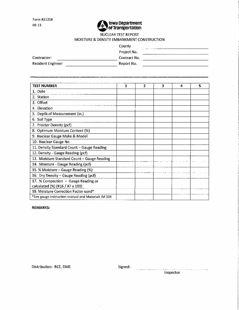
D
OC
UM
ENTA
TION


April 17, 2014 Matls. IM 208 Supersedes October 16, 2012 Appendix B
8
Contractor/Producer: Location:
Certified Technician: Certification No:
Balances (Iowa Test Method 917) Yes No Updated balance calibration records available?
Check balance using 500 gm & 1000 gm calibrated weights?
Is balance accurate to 0.1%?
Sieves Are the sieves in good condition (no loose frames, holes, or tears)?
Mold, Base, and Rammer Are they in good condition. Mold round and the base flat?
If not, check the dimensions for out-of-tolerance.
Rigid Foundation
Do they have a concrete pad or floor or other rigid foundation to compact the specimen on?
Comments:
cc:Materials Engineer Inspected By: Contractor/Producer Ames Date Inspected: File
SOILS FIELD LABORATORY INSPECTION QUALITY CONTROL CHECKLIST
(IM 309)


AA
SHTO
NU
CLEA
R
M
ETHO
D IN
FO

IN-PLACE DENSITY AND MOISTURE CONTENT OF
SOIL AND SOIL-AGGREGATE BY
NUCLEAR METHODS (SHALLOW DEPTH)
AASHTO T 310
Developed by
Multi-Regional Soils & Certification Group Revised 2006
August, 2006 Soil-T310-ii
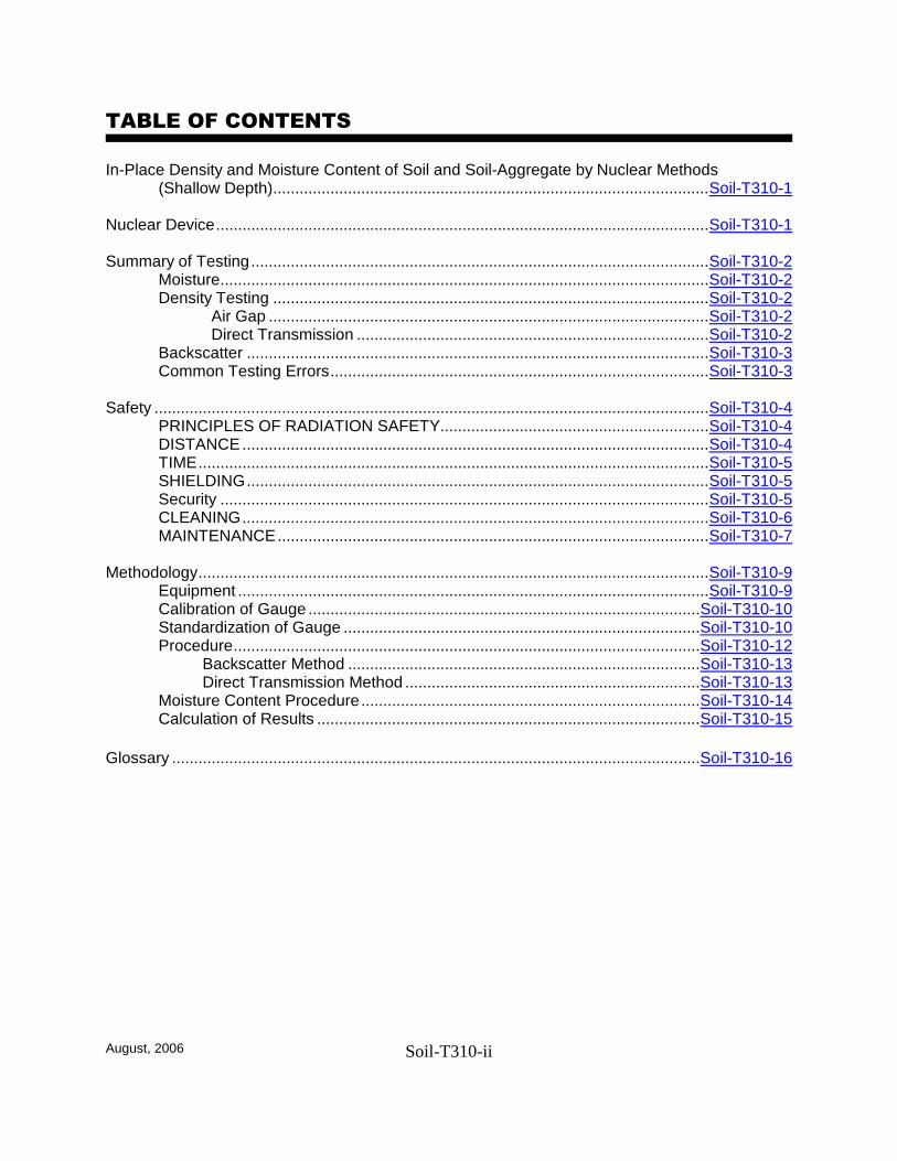
TABLE OF CONTENTS In-Place Density and Moisture Content of Soil and Soil-Aggregate by Nuclear Methods
(Shallow Depth)...................................................................................................Soil-T310-1 Nuclear Device................................................................................................................Soil-T310-1 Summary of Testing........................................................................................................Soil-T310-2 Moisture...............................................................................................................Soil-T310-2
Density Testing ...................................................................................................Soil-T310-2 Air Gap ....................................................................................................Soil-T310-2 Direct Transmission ................................................................................Soil-T310-2
Backscatter .........................................................................................................Soil-T310-3 Common Testing Errors......................................................................................Soil-T310-3
Safety ..............................................................................................................................Soil-T310-4
PRINCIPLES OF RADIATION SAFETY.............................................................Soil-T310-4 DISTANCE..........................................................................................................Soil-T310-4 TIME....................................................................................................................Soil-T310-5 SHIELDING.........................................................................................................Soil-T310-5 Security ...............................................................................................................Soil-T310-5 CLEANING..........................................................................................................Soil-T310-6 MAINTENANCE..................................................................................................Soil-T310-7
Methodology....................................................................................................................Soil-T310-9
Equipment ...........................................................................................................Soil-T310-9 Calibration of Gauge .........................................................................................Soil-T310-10 Standardization of Gauge .................................................................................Soil-T310-10 Procedure..........................................................................................................Soil-T310-12 Backscatter Method ................................................................................Soil-T310-13 Direct Transmission Method ...................................................................Soil-T310-13 Moisture Content Procedure.............................................................................Soil-T310-14 Calculation of Results .......................................................................................Soil-T310-15
Glossary ........................................................................................................................Soil-T310-16

August, 2006 Soil-T310-1
In-Place Density and Moisture Content of Soil and Soil-Aggregate In-Place by Nuclear Methods (Shallow Depth) Density is a function of mass (weight) divided by volume. The more closely pressed together the individual particles of a quantity of material are, the more dense it is. The farther apart they are, separated by air spaces (voids), the less dense the material is. When the individual particles of the same mass (weight) of material are pressed tightly together (compacted), the mass (weight) takes up less volume than when the particles are farther apart. In order to ensure that the embankment, base course, or other earthwork structure will be strong enough to support its intended design load, it must be compacted, made dense. Most specifications will require that the field earthwork be compacted to a specified percent of a target density called maximum density. The nuclear device is one device that is used to determine if the earthwork in the field has met this requirement (in-place density). To determine the dry density of a soil in-place it is necessary to also determine the moisture content of the soil. Nuclear Device The nuclear device is a portable source containing a radioactive source, electronics and rechargeable battery packs. The device uses radiation (a gamma source and a gamma detector) to obtain several different readings. These readings are then calculated to acquire a number for in-place or dry density for soils and soil-aggregate mixtures. Density readings for depths between 50mm and 300mm (2 in. and 12 in.) (depending upon the method used) can be determined.
August, 2006 Soil-T310-2
Summary of Testing Since a density reading and a moisture reading are required to determine dry density, both values have to be determined. A separate radioactive source is necessary for each technique. The nuclear device may have a radioactive source at the tip of its probe or source rod and another source located in the body of the device. Some devices may have both sources located in the probe. At the back of the device, at opposite ends from the probe are detector tubes (Geiger-Muller tubes). Once the test is underway, these detector tubes pick up or count the gamma rays that travel through the material to them and relay this count to the master controls inside the body of the device . A certain percentage of gamma rays emitted by the source is absorbed by the soil, a certain percentage is scattered in the material and a certain percentage will pass through the material. The detector counts the rays that pass through the material and this count is relayed to the master control, called a scaler, by means of electrical impulses. The number of rays counted depends on the density of the material. The higher the density of the material the lower the gamma ray count.
Moisture The nuclear gauge uses a fast neutron source and a thermal neutron detector which determines the intensity of slow or moderated neutrons. Moisture is determined by the relationship of nuclear count to mass of water per unit volume of soil. The moisture content is used in conjunction with the density measurement to determine dry density.
Density Testing Three methods for determining density are covered by AASHTO T238: Method A, or Backscatter mode, Method B, Direct Transmission, and Method C, Air Gap. Each method uses a different test geometry (the geometric space of the test area changes) and should be used where appropriate. Generally, backscatter is used when the properties of the first few inches are concerned (such as density of hot mix asphalt), and direct transmission is used when the properties of 50mm - 30mm (2 in.-12 in.) are concerned (such as 150mm (6 in.) lifts of compacted backfill). Air Gap The air gap method which some older gauge models utilized has now been antiquated by technology. Direct Transmission To determine in-place density with a nuclear device, you will first prepare a smooth area on which to place the device. You will then place the nuclear device on the prepared surface and check to be sure that it is solidly seated with maximum contact between the device and the surface of the material being tested. Then place the device to the side and drill a small hole through the layer or lift being tested. Replace the device in the prepared area, in the same orientation as before, with the probe directly over the hole. Insert the probe into the hole and operated the device in accordance with the manufacturer’s instructions.

August, 2006 Soil-T310-3
Backscatter To determine in-place density in the backscatter mode, perform the test in the same manner as described under Direct Transmission, with the exception of drilling the hole and lowering the probe. Operate the device in backscatter mode in accordance with the manufacturer’s instructions. Special considerations when reporting density measurements as determined by the nuclear gauge: It should be noted that the volume of soil or soil-aggregate represented in the measurements is indeterminate and will vary with the source - detector geometry of the equipment used and with the characteristics of the material tested. In general, and with all other conditions constant, the more dense the material, the smaller the volume involved in the measurement. The density so determined is not necessarily the average density within the volume involved in the measurement. For the usual density conditions, the total count is largely determined by the upper 75 mm to 100 mm (3 to 4 inches) of soils and soil aggregates.
Common Testing Errors Test results may be affected by:
Soil chemical composition Soil not homogenous Equipment not calibrated properly Surface texture Testing to close to a vertical wall or other mass (e.g., cars, construction equipment,
body of water, large pipe) Groups of observers gathered too close to device during operation Presence of asphaltic materials, recycled Pcc, cement, lime, flyash, etc. in soil
materials

August, 2006 Soil-T310-4
Safety The device used for density testing is like any other tool you use on the job. It is there to make your job of taking accurate density readings easier and more efficient. It can be dangerous if used improperly. However, this device is different in that the danger it poses is invisible. Radiation poisoning is very serious. This is why taking proper safety precautions is so vital when dealing with this machine at any level. The following safety rules are simple to follow and will cause you very little inconvenience. If you follow them correctly, the nuclear device will be one of the safest tools you use. There are two important facts to remember when working with nuclear devices. One, the device is radioactive and, two, the device is very expensive. It must always be handled carefully and treated with the utmost respect. It is important to take care of the nuclear device, but it is also important to take care of yourself while you are using it. This section will give guidelines on how to handle the devices with a minimum amount of radiation exposure. You should not be afraid of radiation, but should have a healthy respect for it. By realizing the dangers involved, you will know the importance of following safety regulations carefully.
PRINCIPLES OF RADIATION SAFETY There are several principles of radiation safety with which you should be familiar before you handle the nuclear device. These principles are known as the ALARA concept: keep radiation exposure As Low As Reasonably Achievable. The first principle is distance. The further someone is from the device the less the radiation exposure. The amount of radiation a person will receive when around a radioactive source is influenced by three factors: the intensity of the source, the person's distance from the source and the length of time the person is exposed to it. The intensity of radiation is inversely proportional to the square of the distance from the source. This is called the Inverse Square Law. This means, for example, that a certain radiation intensity at 3 m (10 ft) from a source will have 1/4 the intensity that it has 1.5 m (5 ft) from the source. Remember, the device is always radioactive. The on/off switch does not turn off the radiation. The second principle is time. You must keep your exposure to a minimum. The third principle is shielding. Shielding is a very important part of radiation safety. Even though shielding is built into our equipment, any objects between you and the source help to cut down on the amount of radiation received. We will discuss each of these principles in more detail. DISTANCE Distance from the radiation source is the most effective way to keep exposure to a minimum because alpha and beta particles travel only short distances through matter, and gamma rays become less intense as the distance is increased. Doubling the distance from a radioactive source reduces the exposure to one-fourth the original value.
August, 2006 Soil-T310-5
For this reason, place the device in the back of the vehicle when transporting it. Also, it is a good precaution to store the device at least 7.5 meters (25 ft) away from working areas whenever possible. The device must be properly marked with the radioactive symbol and kept locked when not in use. This means that the device itself must be locked and kept inside the storage case. The room in which the device is stored must also be kept locked. A closet, storage room or a cabinet may be used as the storage area if it meets the criteria described. Ideally, the storage area should have only one door and no windows. The door must have a lock. If storage cabinets are selected as the storage site, the cabinet must be securely and permanently attached to the structure of the facility. Store the nuclear device in its appropriate case. Designate the area selected as the authorized storage location by installing a permanent sign in clear view, preferably on the access door. The sign is yellow in color, and bears the official symbol and the words "CAUTION - RADIOACTIVE MATERIALS." If a radioactive source is lost or stolen, immediately notify your gang supervisor. There must also be a “Notice To Employees” sign posted where the device is stored.
TIME Time of exposure must be monitored carefully so anyone working with the device is checked for exposure to radiation. Each operator or handler of radioactive devices should wear a TLD (Thermoluminescent Dosimetry) badge or similar device, on his or her outer clothing when using or transporting these devices. The amount of radiation to which the wearer has been exposed is indicated by these badges. The badge is checked regularly for radiation exposure. It is replaced by a new badge. The badges are never reused. Badges are not interchangeable between operators. The badge you are issued is numbered for identification; you must always wear your own badge. Be careful with your badge because it is the means by which your exposure to radiation is measured. Your badge should not be exposed to radiation when you are not wearing it. This means that you should not store your badge in or near the nuclear equipment box. Also, you should not keep your badge on the dashboard of your vehicle. The sun can melt the holder, and ruin the badge. If your badge measures exposure, you want to be sure it came from the device, and not some other source. Wear your badge on the upper torso, somewhere between the beltline and the top of the head. Ideally, your badge should be worn in the chest area.
SHIELDING Proper shielding also reduces exposure. The source encapsulation and shielding stop any alpha and beta particles that are produced by the source because the source is well protected. The radioactive sources in most devices are classified as special form, encapsulated sealed sources. With normal device use, no extra shielding methods are required or necessary. However, anything placed between you and a radiation source is a deterrent to radiation penetration. Never attempt to remove the source. As long as the source is intact, it is safe. You will be required to transport your nuclear device to various sites where testing is needed. The device is to be transported to the testing site in a truck, carry-all or station wagon. The device is to be kept securely in its case whenever it is not in use.

August, 2006 Soil-T310-6
It must not be jarred. The mechanical and electronic parts of the device are very durable, but the radiation detectors contain fine wires with glass and ceramic seals that can be damaged by severe jarring. Damage to these parts can cause the device to malfunction. During transport, it must be padded and supported to prevent damage. If transported in a truck, the carrying case shall be secured by lock and chain to the truck. Therefore, be careful to never drop the device, leave it in the way of construction equipment, or transport it unsecured. The most important thing to remember is use common sense. Follow these guidelines for safe operation of the nuclear device:
Do not attempt to use the equipment unless you have been authorized to do so and have been properly trained.
Keep the source in a “safe” or stored position when not in use.
Always wear your safety badge when using the nuclear device.
Never exchange your badge or loan it to another operator.
All unauthorized personnel should be kept out of the operating area.
Keep the nuclear device locked when not in use.
Never leave the nuclear device unattended, except when properly stored.
Return the nuclear device to its proper storage location when not in use.
Security Security must always be maintained at 3 levels:
Lock on device Device in locked case Device in locked case in locked storage area or locked transport vehicle.
CLEANING The nuclear device must be kept as clean as possible at all times. Dirt and dust from the field can build up and cause delicate mechanisms within the machine to malfunction. The device must be cleaned before and after use. When cleaning, put the source rod in the safe storage position. This safe position is obtained by making sure that the index rod is pulled up to the top position and that the trigger button is released. To clean the outside of the device, use mild soap and water on a damp cloth. Before use, wipe the bottom of the device with a long handled brush to remove any dust and moisture. Turn the bottom away from you when doing this. Do the same when you are finished taking your reading. Make sure to clean off the device before it is stored in its case.

August, 2006 Soil-T310-7
More extensive cleaning may be required if you encounter any of the following problems:
Difficulty in lowering/raising the source rod. This may indicate a need to replace the scraper ring. The device is designed with a scraper ring on the bottom plate to keep the area of the source rod free of material that could cause damage to the vertical bearings inside the cavity above the bottom plate. Regular cleaning of this cavity will assure a long trouble-free working life. Cleaning frequency can vary from everyday - when testing wet soils, sands, etc., to a maximum of 2 weeks for normal conditions. Replacement of the scraper ring is recommended as needed. If the source rod is cleaned with a long handle brush when working with materials that stick to the rod, the cavity will only need cleaning once or twice a year.
When the source rod is raised to the “safe” position, no “click” is heard from the tungsten
shield striking the back of the shield cavity.
Erratic density or moisture standard counts. Occasionally, bottom shield removal is required to clean the cavity beneath the source. Cleaning that requires removal of the shield should be done by authorized personnel only, wearing a badge, and following all safety precautions. If the source rod cannot be retracted into the safe position, isolate the device and call your supervisor immediately. Clean and lubricate in accordance with manufacture’s instructions. If the device has been out in extremely wet or humid weather, or if you have been in a cold environment and store the device in a heated space, condensation may form on the inside of the device. Normally, this is not a problem as condensation from the latter condition is so minimal that it dissipates overnight, reducing moisture accumulation in the interior. A hair dryer may also be used to dry out the inside of a wet device. If the gaskets are not tight, wet and very humid conditions are another problem because humidity inside may cause erratic or fluctuating moisture readings as well as possible damage to electronic equipment.
MAINTENANCE Authorized personnel will perform all maintenance, except when removal of the source from the device is required. For this type of maintenance, the device must be returned to the manufacturer. There are two tests performed on the device every six months, the leak test and inspection of the equipment. The leak test ensures that the source materials remain sealed so that the equipment and the areas around the source are not contaminated. The inspection test includes inspecting all radioactive labels for readability, operation of the shutter, presence of two locks on the equipment and the physical condition of the equipment. Both tests must be done on or before the due date of the leak test. In the event the device cannot be leak tested on or before the due date, the device must be taken out of use on this date and stored in a protected and secure location until the test can be performed. Follow the standard regulations and procedures for you organization. If the device or any part of it is lost or stolen, follow the regulations and procedures of your organization.

August, 2006 Soil-T310-8
These methods utilize “radioactive materials which may be hazardous to the health of users unless proper precautions are taken.1” The Federal Government “strongly recommends that users of this equipment become completely familiar with possible safety hazards and that they establish effective operator instruction and use procedures together with routine safety procedures such as routine source-leak tests, the routine recording and evaluation of film badge data, the use of survey meters, etc. In connection with the operation of equipment of this type.2”
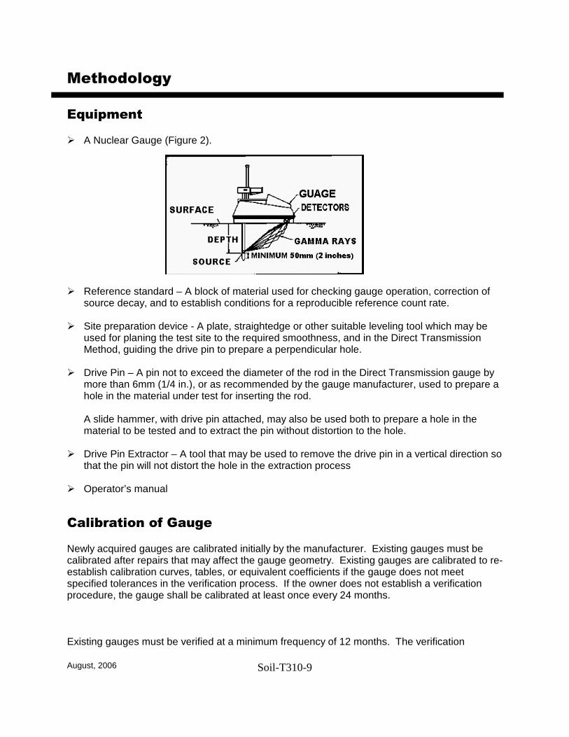
August, 2006 Soil-T310-9
Methodology
Equipment
A Nuclear Gauge (Figure 2).
Reference standard – A block of material used for checking gauge operation, correction of source decay, and to establish conditions for a reproducible reference count rate.
Site preparation device - A plate, straightedge or other suitable leveling tool which may be
used for planing the test site to the required smoothness, and in the Direct Transmission Method, guiding the drive pin to prepare a perpendicular hole.
Drive Pin – A pin not to exceed the diameter of the rod in the Direct Transmission gauge by more than 6mm (1/4 in.), or as recommended by the gauge manufacturer, used to prepare a hole in the material under test for inserting the rod. A slide hammer, with drive pin attached, may also be used both to prepare a hole in the material to be tested and to extract the pin without distortion to the hole.
Drive Pin Extractor – A tool that may be used to remove the drive pin in a vertical direction so that the pin will not distort the hole in the extraction process
Operator’s manual
Calibration of Gauge Newly acquired gauges are calibrated initially by the manufacturer. Existing gauges must be calibrated after repairs that may affect the gauge geometry. Existing gauges are calibrated to re-establish calibration curves, tables, or equivalent coefficients if the gauge does not meet specified tolerances in the verification process. If the owner does not establish a verification procedure, the gauge shall be calibrated at least once every 24 months. Existing gauges must be verified at a minimum frequency of 12 months. The verification

August, 2006 Soil-T310-10
process and resultant tolerances obtained over the depths that the gauge will be operated must be formally recorded and documented. If the verification process indicates a variance beyond the specified tolerances, the gauge must be calibrated. Calibration or verification of the gauge is conducted on blocks of material with known density and moisture content. Calibration or verification procedures are typically conducted by the manufacturer or an independent vendor, but may be conducted by your agency. It is usually not the responsibility of the inspector.
Standardization of Gauge. All nuclear density/moisture gauges are subject to long-term aging of the radioactive sources, detectors, and electronic systems, which may change the relationship between count rates and the material density and water content. To offset this aging, gauges are calibrated as a ratio of the measurement count rate to a count rate made on a reference standard or to an air-gap count (for the backscatter/air-gap ratio method). Standardization of the gauge on the reference standard is required at the start of each day’s use and a permanent record of these data shall be retained. The standardization shall be performed with the gauge at least 10m (30 ft.) away from other nuclear density/moisture gauges and clear of large masses of water or other items which may affect the reference count rates. Standard counts should be taken in the same environment as the actual measurement counts. The following procedure should be used to take the daily standard count: 1. Turn on the gauge and allow for stabilization according to the manufacturer’s
recommendations. If the gauge is to be used either continuously or intermittently during the day, it is best to leave it in the “power on” condition to prevent having to repeat the stabilization (refer to manufacturer recommendations). This will provide more stable, consistent results.
2. Using the reference standard, take at least four repetitive readings at the normal
measurement period and calculate the average count. If available on the gauge, one measurement of four or more times the normal period is acceptable. This constitutes one standardization check.
3. Use the procedure recommended by the gauge manufacturer for determining compliance
with the gauge calibration curves. Without specific recommendations, use the procedure provided below.
NS = N0 1.96 (N0/F)
where: NS = value of current standardization count, N0 = average of the past four values of NS taken for prior usage, and F = factory pre-scale factor (contact gauge manufacturer for the factor).

August, 2006 Soil-T310-11
4. If the mean of the four repetitive reading is outside the limits set by the equation below, repeat the standardization check. If the second standardization check satisfies the equation, the gauge is considered in satisfactory operating condition. If the second check does not satisfy the equation, the gauge needs to be verified as outlined in “Gauge Calibration”. If the verification shows that there is no significant change in the calibration curve, a new reference standard count, NO, should be established. If the verification check shows that there is a significant difference in the calibration curve, the gauge will needed to be repaired and recalibrated.
August, 2006 Soil-T310-12
Procedure 1. Select a location where the gauge will be at least 150mm (6 in.) away from any vertical
projection. If closer than 600mm (24 in.) to a vertical mass, such as in a trench, follow gauge manufacturer correction procedures.
2. Remove all loose and disturbed material and additional material as necessary to expose the
top of the material to be tested.
3. Prepare a horizontal area sufficient in size to accommodate the gauge, by planning the area
to a smooth condition so as to obtain maximum contact between the gauge and material being tested.
4. The maximum void space beneath the gauge shall not be more than 3mm (1/8 in.). Use
native fines or fine sand to fill these voids and smooth the surface with a rigid plate or other suitable tool. The depth of the filler should not exceed approximately 3mm (1/8 in.).
When within 600mm (24 in.) of a wall in a trench the gauge might read the hydrogen contained in the wall as well as the material under test. In such a situation use the trench correction program contained within the gauge or other manufacturer correction procedure. The procedure will likely instruct you to place the standard block in the trench and then take a second reference count which will be compared to the standard, at which point adjustments (if necessary) will be made.
Note about Trench Correction
The volume of material that you wish to be tested with the gauge should be considered when determining the depth at which the gauge is to be seated.
Note
Note
The placement of the gauge on the surface of the material to be tested is critical to the successful determination of density. The optimum condition is total contact between the bottom surface of the gauge and the surface of the material being tested. When optimal conditions are not present, correct surface irregularities by the use of sand or similar filler material. The total area filled should not exceed 10 percent of the bottom area of the gauge. Several trial seatings may be required to achieve these conditions.
August, 2006 Soil-T310-13
5. Turn on and allow the gauge to stabilize (warm up) according to the manufacturer’s recommendations.
6. Continue by using either the steps listed under the “Backscatter or Backscatter/Air-Gap Ratio
Method”, or the “Direct Transmission Method” depending on the method selected for your test.
Backscatter or Backscatter/Air-Gap Ratio Method
7. Seat the gauge firmly. 8. Keep all other radioactive sources at least 10m (30 ft.) away from the gauge to avoid
affecting the measurement. 9. Set the gauge in the Backscatter (BS) position.
10. Secure and record one or more one-minute readings. When using the backscatter/air-gap
ratio method, follow the manufacturers instructions regarding gauge set up. Take the same number of readings for the normal measurement period in the air-gap position as in the standard backscatter position. Determine the air-gap ratio by dividing the counts per minute obtained in the air-gap position by the counts per minute obtained in the standard position. Many gauges have built-in provisions for automatically calculating the air-gap ratio and wet density.
11. Determine the in-place wet density by use of the calibration curve previously established or
read the gauge directly if so equipped.
Direct Transmission Method 7. Select a test location where the gauge in test position will be at least 150mm (6 in.) away
from any vertical projection. 8. Make a hole perpendicular to the prepared surface using the guide and the hole-forming
device. The hole shall be a minimum of 50mm (2 in.) deeper than the desired measurement depth and of an alignment that insertion of the probe will not cause the gauge to tilt from the plane of the prepared surface.
9. Mark the test area to allow the placement of the gauge over the test site and to allow the alignment of the source rod to the hole. Follow manufacturer recommendations if applicable.
10. Remove the hole forming device carefully to prevent the distortion of the hole, damage to the surface, or loose material to fall into the hole.
As a safety precaution, do not extend a rod containing radioactive sources out of its shielded position prior to placing on the test site. Always align the gauge so as to allow placing the rod directly into the test position from the shielded position.
Note
August, 2006 Soil-T310-14
11. Place the gauge on the material to be tested, making sure of maximum surface contact as
described in Step 4. 12. Lower the source rod into the hole to the desired test depth. Pull gently on the gauge in the
direction that will bring the side of the probe to face the center of the gauge so that the probe is in intimate contact with the side of the hole in the gamma measurement path.
13. Keep all other radioactive sources at least 10m (30 ft.) away from the gauge to avoid affecting the measurement.
14. If the gauge is so equipped, set the depth selector to the same depth as the probe before
recording the automated (gauge computed densities, moisture contents, and weights) values.
15. Secure and record one or more one-minute readings. The gauge may be rotated about the
axis of the probe to obtain additional readings. 16. Determine the in-place wet density by use of the calibration curve previously established or
read the gauge directly if so equipped.
Moisture Content Procedure Unless your gauge simultaneously tests for wet density and moisture content, once the wet density has been determined and before moving the gauge, set the controls to the MOISTURE MODE and take a series of one or more one-minute readings. The unit will now display the unit weight of water measured. Pressing a control button on most gauges will result in the dry density being displayed automatically. See the manufacturer’s instructions to operate your individual unit.
Note As a safety precaution, do not extend a rod containing radioactive sources out of its shielded position prior to placing on the test site. Always align the gauge so as to allow placing the rod directly into the test hole from the shielded position.
NOTE: The nuclear device reads hydrogen ions as water. It also can be affected by minerals or chemicals that are neutron absorbers (e.g., boron, cadmium). Because of this, the mineral composition of a soil may cause the moisture content determined by a nuclear device to be inaccurate. Since density and moisture content bear a direct relationship to each other an inaccurate moisture content will yield an inaccurate density reading. To guard against this type of error, you should always clear the moisture content from the nuclear device for a given soil or soil-aggregate with AASHTO T 265 before relying on the nuclear moisture.

August, 2006 Soil-T310-15
Calculation of Results If dry density is required, the in-place water content may be determined by using the nuclear methods described above, by obtaining samples and testing in the laboratory, or by other approved methods. If the water content is determined by nuclear methods, use the gauge readings directly, or, subtract the kg/m3 (lbm/ft3) of moisture from the kg/m3 (lbm/ft3) of wet density, and obtain dry density in kg/m3 (lbm/ft3). If the water content is determined by other methods, and is in the form of percent, calculate the dry density using the following equation: d = 100/(100+w) x m d = Dry density in kg/m3 (lbm/ft3), m = wet density in kg/m3 (lbm/ft3), and w = water as a percent of dry mass Percent Compaction It may be desired to express the in-place density as a percentage of some other density, for example, the laboratory densities determined in accordance with AASHTO Test Methods T 99 and T 180. This relation can be determined by dividing the in-place density by the laboratory density and multiplying by 100. Calculations for determining relative density are provided in ASTM D 4253 or D 4254. Corrections fro oversize material, if required , should be performed in accordance with AASHTO T 224 or ASTM D 4718. If representative samples of material are to be taken for purposes or correlation with other test methods or rock correction, the volume measured can be approximated by a 200mm (8 in.) diameter cylinder located directly under the center line of the radioactive source and detector(s). The height of the cylinder to be excavated will be the depth setting of the source rod when using the Direct Transmission method or approximately 75mm (3 in.) when using the Backscatter method. An alternate to the correction for oversize particles that can be used with mass density methods or minimal oversize situations, involves multiple tests. Three tests may be take at adjacent location and results averaged to get a representative value. Comparisons need to be made to evaluate whether the presence of a single large rock or void in the soil is producing unrepresentative values of density. Whenever values obtained are questionable, the test volume site should be excavated and visually examined to determine whether or not the material tested was representative of the laboratory density sample.
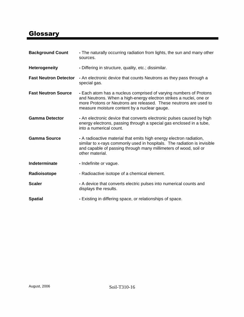
August, 2006 Soil-T310-16
Glossary Background Count - The naturally occurring radiation from lights, the sun and many other
sources. Heterogeneity - Differing in structure, quality, etc.; dissimilar. Fast Neutron Detector - An electronic device that counts Neutrons as they pass through a
special gas. Fast Neutron Source - Each atom has a nucleus comprised of varying numbers of Protons
and Neutrons. When a high-energy electron strikes a nuclei, one or more Protons or Neutrons are released. These neutrons are used to measure moisture content by a nuclear gauge.
Gamma Detector - An electronic device that converts electronic pulses caused by high
energy electrons, passing through a special gas enclosed in a tube, into a numerical count.
Gamma Source - A radioactive material that emits high energy electron radiation,
similar to x-rays commonly used in hospitals. The radiation is invisible and capable of passing through many millimeters of wood, soil or other material.
Indeterminate - Indefinite or vague. Radioisotope - Radioactive isotope of a chemical element. Scaler - A device that converts electric pulses into numerical counts and
displays the results. Spatial - Existing in differing space, or relationships of space.