soil settlement gage model ssg - … · the soil settlement gage model ssg was developed to provide...
TRANSCRIPT
INSTRUCTION MANUAL SOIL SETTLEMENT GAGE
Model SSG
Roctest Limited, 2005, 2017. All rights reserved.
This product should be installed and operated only by qualified personnel. Its misuse is potentially dangerous. The Company makes no warranty as to the information furnished in this manual and assumes no liability for damages resulting from the installation or use of this product. The information herein is subject to change without notification.
Tel.: 1.450.465.1113 • 1.877.ROCTEST (Canada, USA) • 33.1.64.06.40.80 (France) • 41.91.610.1800 (Switzerland)
www.roctest.com
E1141A-170216

i
TABLE OF CONTENTS
1 PRODUCT ............................................................................................................... 1
2 DATA READING AND REDUCTION ....................................................................... 2
2.1 Pre-installation acceptance reading................................................................... 2
2.1.1 Non saturated ............................................................................................ 2
2.1.2 Saturated ................................................................................................... 2
2.2 Post-installation initial reading ........................................................................... 2
2.3 General remarks ............................................................................................... 2
2.4 Manual reading ................................................................................................. 3
2.5 Automatic reading ............................................................................................. 3
2.6 Data reduction ................................................................................................... 3
2.6.1 Pressure reading ........................................................................................ 3
2.6.2 Temperature and boarometric reading ....................................................... 5
2.6.3 Temperature and barometric corrections .................................................... 5
2.6.4 Settlement calculation ................................................................................ 6
2.7 Data reading and reduction for fibre optic sensor .............................................. 7
2.7.1 Preparation for initial reading ..................................................................... 7
2.7.2 Data reduction ............................................................................................ 7
2.7.3 Settlement calculation ................................................................................ 8
3 INSTALLATION PROCEDURES ............................................................................. 9
3.1 Saturation of the SSG system ........................................................................... 9
3.2 Verification ...................................................................................................... 11
3.3 Installation procedure ...................................................................................... 11
3.3.1 Installation in fill ........................................................................................ 12
3.3.2 Installation in borehole ............................................................................. 12
3.3.3 Alternate borehole installation .................................................................. 13
3.3.4 Installation in concrete ............................................................................. 13
3.3.5 Installing the reservoir .............................................................................. 13
3.4 General precautions ........................................................................................ 13
3.5 Maintenance ................................................................................................... 14
3.6 Troubleshooting .............................................................................................. 14
4 MISCELLANEOUS ................................................................................................ 15
4.1 Environmental factors ..................................................................................... 15
4.2 Conversion factors .......................................................................................... 15
4.3 Calibration sheet ............................................................................................. 16
E1141A-170216
1
1 PRODUCT
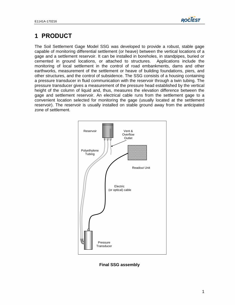
The Soil Settlement Gage Model SSG was developed to provide a robust, stable gage capable of monitoring differential settlement (or heave) between the vertical locations of a gage and a settlement reservoir. It can be installed in boreholes, in standpipes, buried or cemented in ground locations, or attached to structures. Applications include the monitoring of local settlement in the control of road embankments, dams and other earthworks, measurement of the settlement or heave of building foundations, piers, and other structures, and the control of subsidence. The SSG consists of a housing containing a pressure transducer in fluid communication with the reservoir through a twin tubing. The pressure transducer gives a measurement of the pressure head established by the vertical height of the column of liquid and, thus, measures the elevation difference between the gage and settlement reservoir. An electrical cable runs from the settlement gage to a convenient location selected for monitoring the gage (usually located at the settlement reservoir). The reservoir is usually installed on stable ground away from the anticipated zone of settlement.
Final SSG assembly
Readout Unit
Pressure Transducer
Reservoir
Polyethylene Tubing
Electric (or optical) cable
Vent & Overflow
Outlet
E1141A-170216
2
2 DATA READING AND REDUCTION
2.1 PRE-INSTALLATION ACCEPTANCE READING
Gage reading should be taken as soon as gages are received to ensure they have not been damaged during shipment.
2.1.1 NON SATURATED
Zero readings should be compared with the factory readings after barometric and temperature corrections are made. Small variations may arise from shocks or excessive vibrations during transportation and do not affect the linearity of the transducer or the calibration factor.
2.1.2 SATURATED
These readings will be different from the readings on the Calibration Data Sheet, as they correspond to the pre-pressure inside the tubing, which varies between 15 to 25 kPa (this pre-pressure will be eliminated when connected to the reservoir). Small variations may arise from shock or excessive vibration during transportation and do not affect the linearity of the transducer or the calibration factor.
2.2 POST-INSTALLATION INITIAL READING
After saturation, installation and stabilization of the SSG, it is necessary to take an initial reading to which all subsequent readings will be compared. Record the linear reading
(called L0), the temperature reading (T0) and the barometric pressure reading (S0).
A special calculation has to be done if using the polynomial relation to convert raw readings into pressure. The coefficient C of the calibration sheet must be recalculated because it depends on temperature and barometric pressure on site, which are different from those in factory. Use the following relation:
0
2
0 BLALC
where: C' = new calibration factor in kilopascal
A, B = calibration factors (see calibration sheet)
L0 = initial reading in LINEAR unit
Note: It is not necessary to apply corrections to pressure calculation at this step, but it is important to record both temperature and barometric pressure.
2.3 GENERAL REMARKS
The SSG is normally equipped with a vibrating wire pressure transducer. The gross reading is a vibration measured as a period (in microseconds) or frequency (in Hz). This gross reading is converted in pressure using the calibration factor furnished on the calibration data sheet. Each transducer is calibrated for that purpose and a calibration data sheet is furnished with each one.
E1141A-170216
3
The pressure transducer measures the absolute pressure and a correction must be done for barometric pressure and temperature variations, as shown in section 2.6.3.
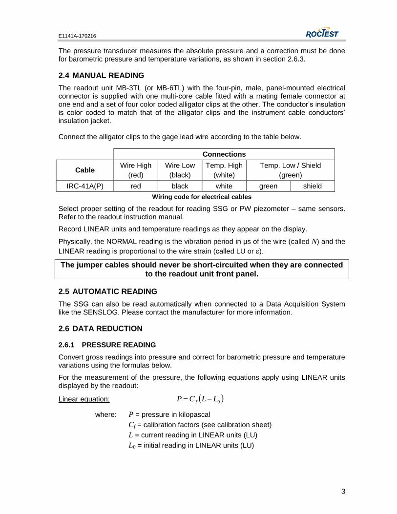
2.4 MANUAL READING
The readout unit MB-3TL (or MB-6TL) with the four-pin, male, panel-mounted electrical connector is supplied with one multi-core cable fitted with a mating female connector at one end and a set of four color coded alligator clips at the other. The conductor’s insulation is color coded to match that of the alligator clips and the instrument cable conductors’ insulation jacket.
Connect the alligator clips to the gage lead wire according to the table below.
Connections
Cable Wire High
(red)
Wire Low
(black)
Temp. High
(white)
Temp. Low / Shield
(green)
IRC-41A(P) red black white green shield
Wiring code for electrical cables
Select proper setting of the readout for reading SSG or PW piezometer – same sensors. Refer to the readout instruction manual.
Record LINEAR units and temperature readings as they appear on the display.
Physically, the NORMAL reading is the vibration period in μs of the wire (called N) and the
LINEAR reading is proportional to the wire strain (called LU or ).
The jumper cables should never be short-circuited when they are connected to the readout unit front panel.
2.5 AUTOMATIC READING
The SSG can also be read automatically when connected to a Data Acquisition System like the SENSLOG. Please contact the manufacturer for more information.
2.6 DATA REDUCTION
2.6.1 PRESSURE READING
Convert gross readings into pressure and correct for barometric pressure and temperature variations using the formulas below.
For the measurement of the pressure, the following equations apply using LINEAR units displayed by the readout:
Linear equation: 0LLCP f
where: P = pressure in kilopascal
Cf = calibration factors (see calibration sheet)
L = current reading in LINEAR units (LU)
L0 = initial reading in LINEAR units (LU)
E1141A-170216
4
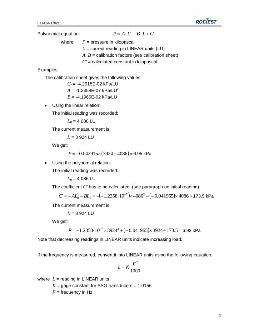
Polynomial equation: CLBLAP 2
where P = pressure in kilopascal
L = current reading in LINEAR units (LU)
A, B = calibration factors (see calibration sheet)
C' = calculated constant in kilopascal
Examples:
The calibration sheet gives the following values:
Cf = -4.2915E-02 kPa/LU
A = -1.2358E-07 kPa/LU2
B = -4.1965E-02 kPa/LU
Using the linear relation:
The initial reading was recorded:
L0 = 4 086 LU
The current measurement is:
L = 3 924 LU
We get:
408639240429150.P 6.95 kPa
Using the polynomial relation:
The initial reading was recorded:
L0 = 4 086 LU
The coefficient C' has to be calculated: (see paragraph on initial reading)
4086041965040861023581 27
0
2
0 ..BLALC 173.5 kPa
The current measurement is:
L = 3 924 LU
We get:
51733924041965039241023581 27 ...P 6.93 kPa
Note that decreasing readings in LINEAR units indicate increasing load.
If the frequency is measured, convert it into LINEAR units using the following equation:
1000
2FKL
where L = reading in LINEAR units
K = gage constant for SSG transducers = 1.0156
F = frequency in Hz
E1141A-170216
5
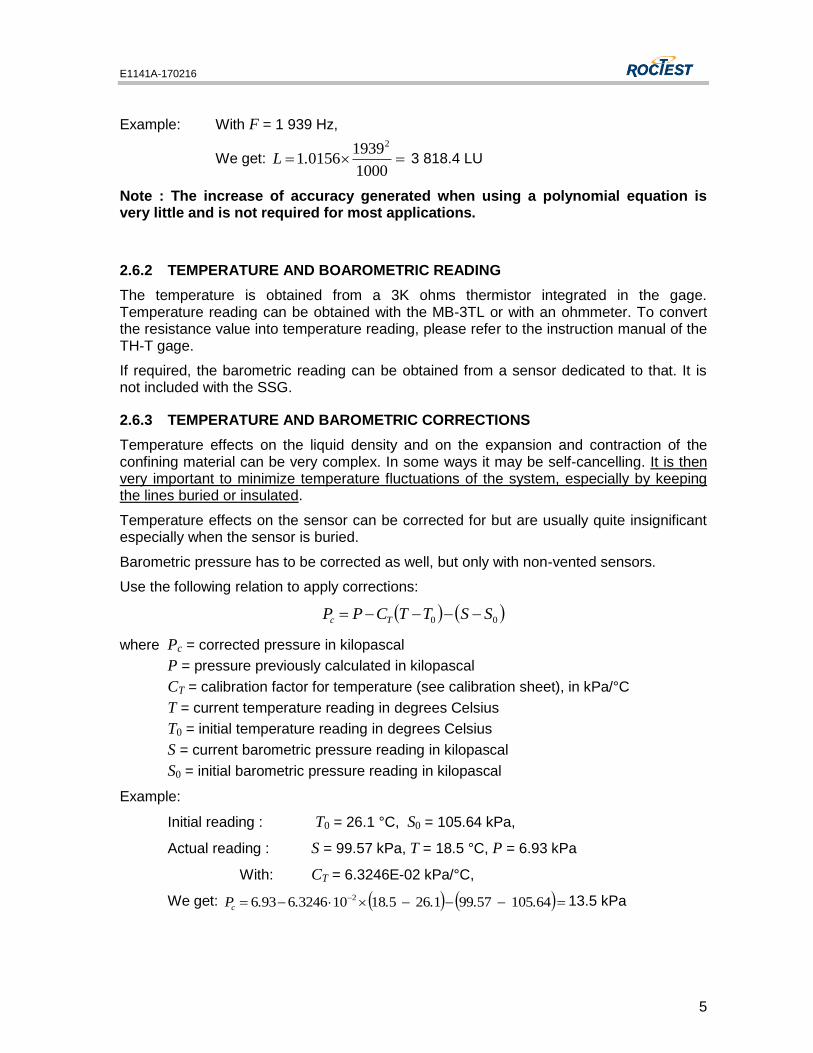
Example: With F = 1 939 Hz,
We get: 1000
193901561
2
.L 3 818.4 LU
Note : The increase of accuracy generated when using a polynomial equation is very little and is not required for most applications.
2.6.2 TEMPERATURE AND BOAROMETRIC READING
The temperature is obtained from a 3K ohms thermistor integrated in the gage. Temperature reading can be obtained with the MB-3TL or with an ohmmeter. To convert the resistance value into temperature reading, please refer to the instruction manual of the TH-T gage.
If required, the barometric reading can be obtained from a sensor dedicated to that. It is not included with the SSG.
2.6.3 TEMPERATURE AND BAROMETRIC CORRECTIONS
Temperature effects on the liquid density and on the expansion and contraction of the confining material can be very complex. In some ways it may be self-cancelling. It is then very important to minimize temperature fluctuations of the system, especially by keeping the lines buried or insulated.
Temperature effects on the sensor can be corrected for but are usually quite insignificant especially when the sensor is buried.
Barometric pressure has to be corrected as well, but only with non-vented sensors.
Use the following relation to apply corrections:
00 SSTTCPP Tc
where Pc = corrected pressure in kilopascal
P = pressure previously calculated in kilopascal
CT = calibration factor for temperature (see calibration sheet), in kPa/°C
T = current temperature reading in degrees Celsius
T0 = initial temperature reading in degrees Celsius
S = current barometric pressure reading in kilopascal
S0 = initial barometric pressure reading in kilopascal
Example:
Initial reading : T0 = 26.1 °C, S0 = 105.64 kPa,
Actual reading : S = 99.57 kPa, T = 18.5 °C, P = 6.93 kPa
With: CT = 6.3246E-02 kPa/°C,
We get: 6410557991265181032466936 2 ......Pc13.5 kPa
E1141A-170216
6
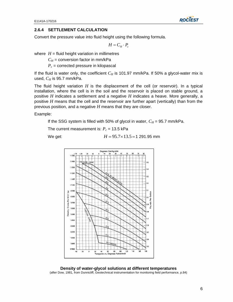
2.6.4 SETTLEMENT CALCULATION
Convert the pressure value into fluid height using the following formula.
cH PCH
where H = fluid height variation in millimetres
CH = conversion factor in mm/kPa
Pc = corrected pressure in kilopascal
If the fluid is water only, the coefficient CH is 101.97 mm/kPa. If 50% a glycol-water mix is
used, CH is 95.7 mm/kPa.
The fluid height variation H is the displacement of the cell (or reservoir). In a typical
installation, where the cell is in the soil and the reservoir is placed on stable ground, a
positive H indicates a settlement and a negative H indicates a heave. More generally, a
positive H means that the cell and the reservoir are further apart (vertically) than from the
previous position, and a negative H means that they are closer.
Example:
If the SSG system is filled with 50% of glycol in water, CH = 95.7 mm/kPa.
The current measurement is: Pc = 13.5 kPa
We get: 513795 ..H 1 291.95 mm
Density of water-glycol solutions at different temperatures (after Dow, 1981, from Dunnicliff, Geotechnical instrumentation for monitoring field performance, p.84)
E1141A-170216
7
2.7 DATA READING AND REDUCTION FOR FIBRE OPTIC SENSOR
2.7.1 PREPARATION FOR INITIAL READING
Gage readings should be taken as soon as the gage is received to ensure it has not been damaged during shipment. All gage transducers are individually calibrated before shipment and a gage factor (7-digit number) and the gage zero obtained at factory are supplied with each gage. Before using a transducer with the Universal fibre optic readout unit from Roctest, its gage factor must first be saved in the readout memory and selected. The calibration factor is already recorded in the transducer's gage factor, which is registered on a label installed on the cable close to the fibre optic connector. It can also be found on the calibration sheet of the gage. Please review the operating manual of the readout unit before proceeding with readings.
First, the gage must be connected in a channel number and the appropriate gage factor must be assigned. Fibre optic pressure transducers must be zeroed at least once to adjust the zero before taking an initial reading. To zero the transducer, follow the instructions given in the operating manual of the readout unit. After the transducer has been zeroed, with the appropriate gage factor pre-selected, the reading will indicate 0 or a very small value. Obviously, the transducer should not be submitted to any pressure when zeroing and should be stabilized in temperature. The zero adjustment of the transducer is necessary when using a pressure transducer for the first time. It is also necessary to take note of the current value at installation of the gage zero (value between 14000 and 24000) when doing a zero adjustment. Knowing it is possible to re-enter the initial gage zero at installation could be useful in case the readout is reset or its memory content is lost. For more information about zero adjustment and taking note of the gage zero see, the operating manual of your readout unit.
You can select the Metric system of unit (reading will be displayed in bars) or the Imperial system of unit (reading will be displayed in psi). See the operating manual of your readout unit for more information about the system of units.
Steps before taking a reading
1. Save gage factor into the readout memory.
2. Connect each gage to one of the channel input connectors.
3. Associate appropriate gage factor to the measuring channel.
4. Zero gages and record the gage zero in internal unit of Fabry-Perot cavity length.
5. Select appropriate system of units.
6. Take initial reading in engineering units.
2.7.2 DATA REDUCTION
2.7.2.1 PRESSURE READING
The fibre optic pressure transducer measures absolute pressure that must be corrected for barometric pressure changes. Also, the sensors are supplied with a temperature correction
E1141A-170216
8
factor, which is used to correct the pressure reading for significant variations in temperature.
To convert changes in readings to changes in pressure corrected for barometric pressure and temperature changes, use the following equation:
Pcorr = Prec – CT (T1 – T0) – (B1 – B0)
where: Pcorr = corrected pressure in bars
Prec = recorded pressure in bars
CT = temperature correction factor in bar/°C
T0, T1 = Initial (at installation) and current temperature readings in °C
B0, B1 = Initial (at installation) and current barometric pressure readings in bars.
Example:
Prec = 4.500 bars
CT = 0.00143 bar/°C
T0 = 20°C
T1 = 25°C
B0 = 1.013 bars
B1 = 1.002 bars
Pcor = 4.500 – 0.00143 (25 – 20) – (1.002 – 1.013)
= 4.504 bars
2.7.3 SETTLEMENT CALCULATION
The change in elevation corresponding to a change in pressure P1 – P0 is determined as follows:
H = CH x (P1 – P0)
where : P0, P1 = initial and current pressure readings converted in kPa.
H = the displacement of the cell (or reservoir) in mm.
If the fluid is water only, the coefficient CH is 101.97 mm/kPa. If 50% of glycol in water is
used, CH is 95.7 mm/kPa.
It should be remembered that the soil settlement gage is a sealed instrument and that the pressure used in the above conversion should account for any change in atmospheric barometric pressure between initial and current reading. Therefore, the P0 and P1 values must be corrected.
In a typical installation, where the cell is in the soil and the reservoir is placed on stable
ground, a positive H indicates a settlement and a negative H indicates a heave.
More generally, a positive H means that the cell and the reservoir are further apart
(vertically) than from the previous reading, and a negative H means that they are closer.
E1141A-170216
9
3 INSTALLATION PROCEDURES
3.1 SATURATION OF THE SSG SYSTEM
WARNING: WHEN THE SSG IS SATURATED, CARE SHOULD BE TAKEN NOT TO HAVE THE VERTICAL DISTANCE BETWEEN THE GAGE AND THE SETTLEMENT RESERVOIR EXCEEDS 150% OF THE RANGE OF THE GAGE. THIS RANGE IS SPECIFIED ON THE CALIBRATION DATA SHEET. FURTHERMORE, THE GAGE MUST ALWAYS BE INSTALLED LOWER THAN THE SETTLEMENT RESERVOIR.
The SSG is usually delivered in separate parts. It should be assembled and filled by the user. For better results, the transducer should be installed and filled in a vertical position. The saturation of the tubes consists of three main steps.
1. De-airing liquid: The liquid inside the tubing must be free of air. De-airing the fluid may be necessary, which can be done by using a vacuum pump and a bell container under which liquid is installed, or with a boiler. De-airing systems are available at most soil mechanics laboratories. When transferring liquid from a recipient to another, agitation must be avoided to prevent reintroduction of air.
2. Saturating the tubing: To minimize air infiltration and accelerate the saturating procedure, water can be filled under pressure using a pump. It can also be done by using only gravity, the reservoir serving as an inlet. Make sure that there is no ascending loop in the tubing, in which air may be trapped.
A simple, inexpensive and fairly effective way of helping to saturate the tubing is by adding a few drops of liquid detergent (about 2 cm³ per litre of water), which will serve as a wetting agent.
WARNING: IF USING A PUMP, BE CAREFUL NOT TO DAMAGE THE SSG TRANSDUCER BY EXCESSIVE PRESSURE. THIS IS PREVENTED BY CONNECTING THE TRANSDUCER TO A READOUT UNIT AND MAKING SURE THE PRESSURE RANGE INDICATED ON THE TRANSDUCERS CALIBRATION DATA SHEET IS NOT EXCEEDED.
3. Connecting the reservoir to the saturated SSG:
- Fill the reservoir up to the excess tube.
- Press on the tip of both quick connects (which are found at the bottom of the reservoir) until some water leaks.
- Bring one of the female quick connects from the double connecting tube close to the reservoir. Maintain it vertically and pour water inside the cavity up to the O-ring. Then, by pressing the compression ring, connect the female connecting tube to the male part of the reservoir. Repeat the process for the other quick connect.
When tubing, transducer and reservoir are filled up, a thin layer of oil must be added on the water surface in the reservoir to prevent water evaporation. The reservoir cover can then be put back.
E1141A-170216
10
Field Saturation Instructions :
• Prepare and de-air the quantity of liquid needed to fill the twin tubing; approximately 300 cc of liquid is needed to fill 10 meters of twin tubing ¼’ in x 0.170 in, plus approximately 250 cc for the reservoir and the sensor. Prepare at least 20% extra liquid.
• Add the wetting agent to the solution and mix gently to minimize air infiltration in the de-aired liquid. Roctest recommends the Kodac© Professional Photo-Flo 200 solution at a ratio of 1:200 parts of water (or anti-freeze solution); liquid detergent or JET-DRY® Rinse Agent could also be adequate.
• Connect the twin tubing to the sensor.
• Install the SSG sensor according to the procedure in the instruction manual.
• There are many ways to fill the twin tubing :
The quickest is to use a pressurized container connected on one tubing and allow the return line to remain open to the atmosphere with a male quick connect or a vacuum negative pressure applied. A garden sprayer on which a connector is installed can be used in this case, but this technique requires special attention because of the pressure involved in this procedure. A low pressure SSG sensor is able to withstand 70 kPa, while a general sprayer that can be found on the market can reach a pressure above that. The use of a pressure regulator is highly recommended, or a constant reading of the sensor, to avoid pressurizing the latter over limit.
Alternately, the easiest and safest method is to use the reservoir to fill the twin tubing by gravity; although, there are some negative points. Primarily, the time involved to fill long twin tubing lengths, which could take several hours with long tubing ( over 75 m) and when it is cold ( some antifreezes gets very viscous at low temperature). Careful observation of reservoir’s liquid level is also very important, because if a reduced liquid level is attained, air can enter the tubing, resulting in bubbles in the column if water is added thereafter. This will produce erratic behavior of the sensor. If this occurs, you will have to restart from the beginning. In order to avoid this, it is preferable to have a reservoir that contains the entire amount of liquid required to fill the tubing. This alternative can be done by making a custom made "drip watering tube" style filling reservoir.
For example, it takes approximately 3 litres to fill a 100-m tubing. In this case, a 4-litre container is appropriate to maintain an adequate SSG reservoir level. To do so, drill a hole in the cover of the container and insert a short length of tubing; fill the 4 litre bottle, install the cover and turn the bottle upside down. It is imperative that the bottle's cover and the tube are water tight. Fix the bottle over the reservoir with the end of the small tubing levelled a little bit under the extremity of the overflow pipe located in the reservoir. When the level in the SSG reservoir will reach the end of the tube, this latter will start to supply the solution drop by drop to maintain the proper level.
Detailed description of this method:
• Fill the reservoir with the water solution near the top of the overflow tube inside.
• Evacuate some water by pushing on the quick connector valves located under the reservoir to purge any trapped air.
E1141A-170216
11
• Connect one of the two tubing’s’ female quick connectors to the reservoir, and connect the supplied vent male quick connect with the small length of tubing at the end of the second tubing (return line). The de-aired/wetting agent solution will begin to fill the tubing. As mentioned above, be patient because it can take several hours to fill a long length of tubing and in some cases almost one day.
• To have an idea of the rate at which the water travels in the tubing, you can immerse the end of the return tubing in a water container (located at a level lower than the reservoir level), to observe the bubbles created by the air expelled from the tubing by the water running into it. Do not leave the return line in this water container for the whole process of saturation since it will slow down the velocity of the water running in the tubing, resulting in a longer filling time.
• When water is observed coming out of the return line, let it circulate for at least 15 to 20 minutes to evacuate the bubbles that could have been created when the water reached and filled the sensor chamber.
• When no more bubbles are observed from the return line, position it vertically and slowly remove the vent quick-connector.
• While holding the return line connector vertically, add a small amount of solution just above the o-ring line to release any trapped air, and connect it to the second connector under the reservoir.
• Adjust the level about 1 mm from the top of the overflow pipe inside the reservoir.
• Add a thin film of oil on the surface of the water solution to avoid evaporation. If environmental issue is important to observe, use vegetable oil.
• Install the cap on the reservoir.
• Take the initial reference reading of the SSG settlement gage.
3.2 VERIFICATION
Before installing the cell, a verification of the system should be made to ensure the cell is accurate. Whether the system is already saturated upon reception or saturated by the user, it must be connected to the reservoir before making tests. Tests are made by moving
the cell by different known heights and comparing those values with the H values
associated with the readings.
3.3 INSTALLATION PROCEDURE
The SSG is usually delivered with installation accessories that can include: an installation bracket for the reservoir, an oil bottle, a wetting agent bottle (a few drops added to the filling water will improve performance) and a connector for flushing/saturating.
The SSG is generally installed directly in a fill or borehole. In order to measure relative vertical displacement between the reservoir and the gage, one of these two (generally the reservoir) must be installed in stable ground whereas the other follows soil movements.
E1141A-170216
12
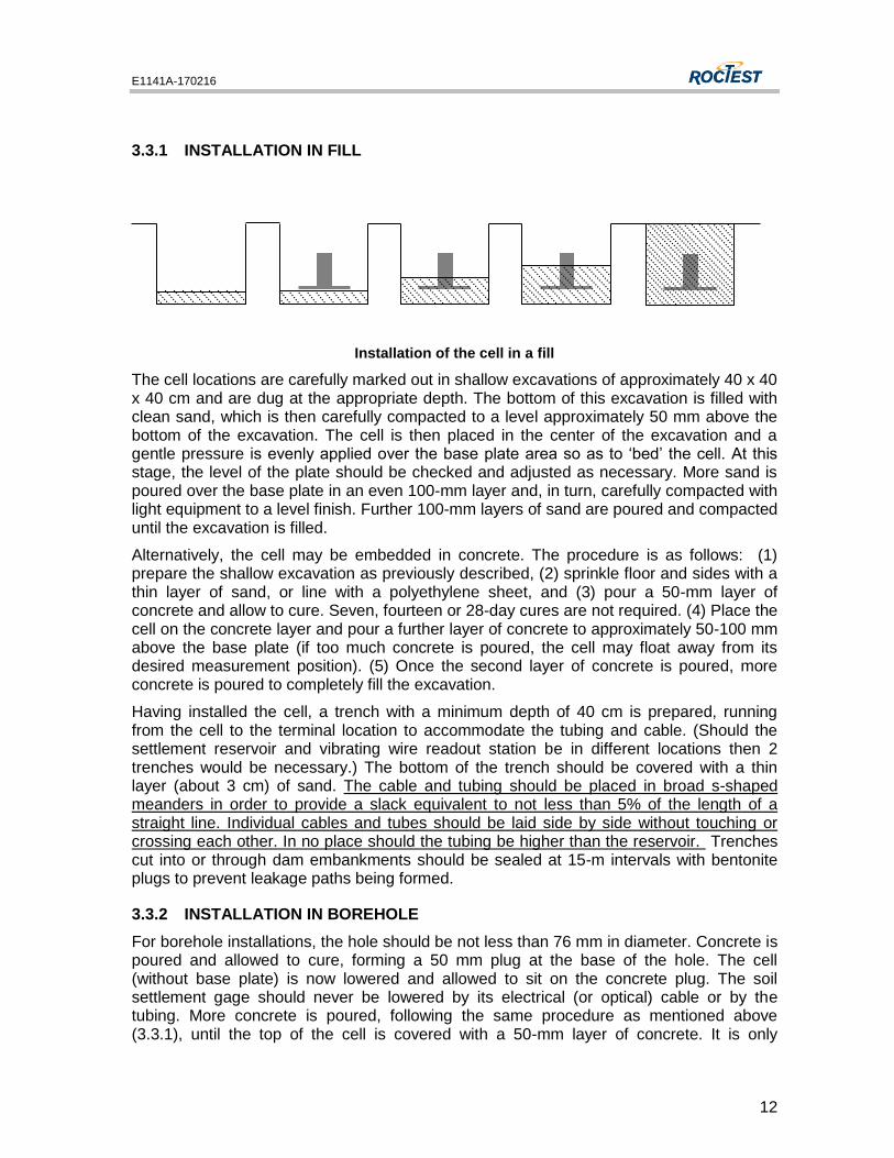
3.3.1 INSTALLATION IN FILL
Installation of the cell in a fill
The cell locations are carefully marked out in shallow excavations of approximately 40 x 40 x 40 cm and are dug at the appropriate depth. The bottom of this excavation is filled with clean sand, which is then carefully compacted to a level approximately 50 mm above the bottom of the excavation. The cell is then placed in the center of the excavation and a gentle pressure is evenly applied over the base plate area so as to ‘bed’ the cell. At this stage, the level of the plate should be checked and adjusted as necessary. More sand is poured over the base plate in an even 100-mm layer and, in turn, carefully compacted with light equipment to a level finish. Further 100-mm layers of sand are poured and compacted until the excavation is filled.
Alternatively, the cell may be embedded in concrete. The procedure is as follows: (1) prepare the shallow excavation as previously described, (2) sprinkle floor and sides with a thin layer of sand, or line with a polyethylene sheet, and (3) pour a 50-mm layer of concrete and allow to cure. Seven, fourteen or 28-day cures are not required. (4) Place the cell on the concrete layer and pour a further layer of concrete to approximately 50-100 mm above the base plate (if too much concrete is poured, the cell may float away from its desired measurement position). (5) Once the second layer of concrete is poured, more concrete is poured to completely fill the excavation.
Having installed the cell, a trench with a minimum depth of 40 cm is prepared, running from the cell to the terminal location to accommodate the tubing and cable. (Should the settlement reservoir and vibrating wire readout station be in different locations then 2 trenches would be necessary.) The bottom of the trench should be covered with a thin layer (about 3 cm) of sand. The cable and tubing should be placed in broad s-shaped meanders in order to provide a slack equivalent to not less than 5% of the length of a straight line. Individual cables and tubes should be laid side by side without touching or crossing each other. In no place should the tubing be higher than the reservoir. Trenches cut into or through dam embankments should be sealed at 15-m intervals with bentonite plugs to prevent leakage paths being formed.
3.3.2 INSTALLATION IN BOREHOLE
For borehole installations, the hole should be not less than 76 mm in diameter. Concrete is poured and allowed to cure, forming a 50 mm plug at the base of the hole. The cell (without base plate) is now lowered and allowed to sit on the concrete plug. The soil settlement gage should never be lowered by its electrical (or optical) cable or by the tubing. More concrete is poured, following the same procedure as mentioned above (3.3.1), until the top of the cell is covered with a 50-mm layer of concrete. It is only
E1141A-170216
13
necessary to cure the concrete to its setting phase; seven, fourteen or 28-day cures are not required. The hole should now be back filled with granular material, which has approximately the same density as the surrounding host material. The cable and the tubing should be placed in a protective tube to prevent damage when filling. At the top of the borehole, the cable and tubing should be run in trenches as described above.
3.3.3 ALTERNATE BOREHOLE INSTALLATION
In some cases, the settlement cell is installed at the bottom of a borehole in stable ground and the reservoir is placed above the cell at or near the borehole collar. Here, the settlement cell does not move and provides a fixed reference to which the reservoir movements are related.
The reservoir is attached to the settlement plate. The cell is lowered to the bottom of the borehole and is grouted in place as described above. The use of threaded lowering rods to support the cell at the desired elevation may be required. The tubing and the cable are coiled within the borehole allowing enough slack to accommodate any anticipated heave of the reservoir. The borehole is back filled as mentioned above.
The settlement plate with the reservoir attached is then fixed in place and the cell electrical (or optical) cable is trenched to a readout location.
3.3.4 INSTALLATION IN CONCRETE
For installations in concrete forms, the cells are generally secured to the reinforcement (rebar). The cable and tubing are tied to the reinforcement at frequent intervals along its length, carefully avoiding kinks and sudden bends.
3.3.5 INSTALLING THE RESERVOIR
The reservoir is usually installed on stable ground away from the anticipated zone of settlement. Its elevation should be surveyed and recorded at the time of installation. The reservoir should never be located where it is exposed to direct sun.
3.4 GENERAL PRECAUTIONS
In any installation, the following precautions should be observed:
- Never lower the settlement cell by its cable or tubing.
- Take precautions to avoid cutting or over stressing of the cable and/or tubing.
- When laying out the cable and tubing, leave sufficient slack so that full settlement range of the system can be accommodated.
- Always wrench-tighten the tube fittings to ensure leak tight seals, never hand tighten these fittings.
- Take and record readings at each installation phase to check for good functioning of the gage.
- Do not submit a saturated system to an elevation greater than the one mentioned in the specification.
E1141A-170216
14
3.5 MAINTENANCE
The reservoir is fitted with a liquid outlet on its side and with a vent tube on its cap. The client must check periodically – especially if readings deviate – the fluid level in the SSG reservoir to ensure that it remains approximately at the same elevation. Water must be added or removed accordingly. Always keep a thin layer of oil on the surface of the water in order to prevent evaporation.
Every 3 month, replace the desiccant capsules. Desiccant turns pink when inactive.
Every 12 months, flush the liquid tubes with fresh de-aired liquid.
Follow the saturation procedure described above.
WARNING: CARE SHOULD BE TAKEN NOT TO APPLY EXCESSIVE PRESSURE ON THE SSG TRANSDUCER WHILE FLUSHING AND RE-SATURATING (REFER TO THE SATURATION SECTION ABOVE).
3.6 TROUBLESHOOTING
Various problems may occur when using the SSG, particularly concerning readings. Here are a few problems, their cause and solutions.
- Readings are always the same (when settlement is expected): the tube is probably pinched. Verify this by changing the height of the reservoir. If indeed the tube is pinched, two solutions are possible. Either find the location of the pinch or try flushing the system.
- Readings are unstable: check for sources of nearby noise as motors, generators, antennas or electrical cables. Isolate the readout from the ground by placing it on a piece of wood or similar non-conductive material.
- Readings vary oddly or only a little: this situation can be caused by different factors. First, there might be air in the tubing. The tubing must be re-saturated periodically. Note that a tube of diameter greater than 6 mm is very hard to keep free of air. Second, great changes in temperature may affect the readings. To adapt to the climate change, use a water-glycol mix in the tubing and a fluid dilatation chart given above. Lastly, the level of fluid in the reservoir can change. This is simply solved by monitoring the water level and adjusting it if needed, and by checking for any leaks.
- Response time is too long: the diameter of the tubing is too small (< 4.3 mm). Either use a larger tubing or be patient.
- Readings are much higher than anticipated: a pressure too great may have been applied to the cell, causing a permanent damage to the diaphragm inside the cell. If the cell can be removed from its emplacement, retrieve it and check if the readings are accurate (see section 3.2). If not, make the same tests, but move the reservoir instead of the cell. If the results are incoherent, the cell is damaged beyond use.

E1141A-170216
15
4 MISCELLANEOUS
4.1 ENVIRONMENTAL FACTORS
Since the purpose of pressure cells installation is to monitor site conditions, factors which may affect these conditions should always be observed and recorded. Seemingly minor effects may have a real influence on the behaviour of the structure being monitored and may give an early indication of potential problems. Some of these factors include, but are not limited to: blasting, rainfall, tidal levels, excavation and fill levels and sequences, traffic, temperature and barometric changes, changes in personnel, nearby construction activities, seasonal changes, etc.
4.2 CONVERSION FACTORS
To Convert From To Multiply By
LENGTH Microns
Millimetres
Meters
Inches
Inches
Feet
3.94E-05
0.0394
3.2808
AREA Square millimetres
Square meters
Square inches
Square feet
0.0016
10.7643
VOLUME
Cubic centimetres
Cubic meters
Litres
Litres
Cubic inches
Cubic feet
U.S. gallon
Can–Br gallon
0.06101
35.3357
0.26420
0.21997
MASS Kilograms
Kilograms
Kilograms
Pounds
Short tons
Long tons
2.20459
0.00110
0.00098
FORCE Newtons
Newtons
Newtons
Pounds-force
Kilograms-force
Kips
0.22482
0.10197
0.00023
PRESSURE AND STRESS
Kilopascals
Bars
Inches head of water
Inches head of Hg
Pascal
Kilopascals
Kilopascals
Kilopascals
Psi
Psi
Psi
Psi
Newton / square meter
Atmospheres
Bars
Meters head of water
0.14503
14.4928
0.03606
0.49116
1
0.00987
0.01
0.10197
TEMPERATURE Temp. in F = (1.8 x Temp. in C) + 32
Temp. in C = (Temp. in F – 32) / 1.8
at 4 C E6TabConv-990505
Conversion factors
E1141A-170216
16
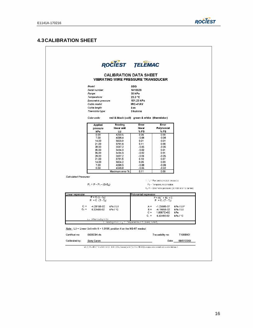
4.3 CALIBRATION SHEET