soil moisture sensor - alpha omega electronics · ec-5 user’s manual 1. introduction 2 customer...
TRANSCRIPT

EC-5Soil Moisture Sensor
User’s Manual
Version 2

Decagon Devices, Inc.2365 NE Hopkins CourtPullman WA 99163 USA
(509) 332-5600
Trademarks:“ECH2O” is a registered trademark
of Decagon, Devices, Inc All rights reserved..
©2001-2012 Decagon Devices, Inc.All rights reserved.

EC-5 User’s ManualTable of Contents
Contents
1. Introduction . . . . . . . . . . . . . . . . 1EC-5 Specifications . . . . . . . . . . . . . . . . . . 1Customer Support . . . . . . . . . . . . . . . . . . . 2Warranty Information . . . . . . . . . . . . . . . 2Seller’s Liability . . . . . . . . . . . . . . . . . . . . . 2
2. About the EC-5 . . . . . . . . . . . . . . 4Sensor Features . . . . . . . . . . . . . . . . . . . . . 4Wiring Diagrams . . . . . . . . . . . . . . . . . . . . 5
3.5mm Plug Wiring . . . . . . . . . . . . . . . 5Wiring to Non-Decagon Data Loggers 5
Extended cable lengths . . . . . . . . . . . . . . . 6
3. Installing the Sensors . . . . . . . . . 7Procedure . . . . . . . . . . . . . . . . . . . . . . . . . . 7
Orientation . . . . . . . . . . . . . . . . . . . . . . 8Removing the Sensor . . . . . . . . . . . . . . 8
4. Collecting Data . . . . . . . . . . . . . . 9Data Logger Requirements . . . . . . . . . . . . 9Connecting to a Data Logger . . . . . . . . . 10Sample Program . . . . . . . . . . . . . . . . . . . 10SCWin (Short Cut) Directions . . . . . . . . 11Calibration . . . . . . . . . . . . . . . . . . . . . . . . 13Troubleshooting . . . . . . . . . . . . . . . . . . . . 16
Declaration of Conformity . . . . . 17
Index . . . . . . . . . . . . . . . . . . . . . . . 19
i


EC-5 User’s Manual1. Introduction
1. Introduction
EC-5 Specifications
Measurement Time: 10ms (milliseconds)
Accuracy: at least 0.03 m3/m3 all soils, up to 8 dS/mWith soil-specific calibration: ±.02 m3/m3 (±2%)
Resolution: 0.001 m3/m3 VWC in mineral soils, 0.25%in growing media
Power Requirements: 2.5VDC - 3.6VDC @ 10mA
Output: 10-40% of excitation voltage (250-1000mV at2500mV excitation)
Operating Environment: -40 to +60 °C
Range of Measurement: 0 to saturation
Sensor dimensions: 8.9cm x 1.8cm x 0.7cm
Cable length: 5m standard, custom lengths or extensioncables are available
Connector types: 3.5 mm plug or stripped and tinnedlead wires
Data Logger Compatibility (not exclusive):Decagon: Em5b, Em50 series loggersCampbell Scientific: CR10X, 21X, 23X, CR1000,CR3000, etc.
1

EC-5 User’s Manual1. Introduction
Customer SupportIf you ever need assistance with your EC-5, or if youjust have questions or feedback, there are several waysto contact us. Customer service representatives areavailable to speak with you Monday thru Friday,between 7am and 5pm Pacific time.
NOTE: If you purchased your EC-5 through a distribu-tor, please contact them for assistance. E-mail: [email protected] or [email protected]
Phone:1-509-332-5600
Fax: 1-509-332-5158
If contacting us by email or fax, please include as part ofyour message your name, address, phone, and fax num-ber along with a description of your problem.
Warranty InformationThe EC-5 has a 30-day satisfaction guarantee and a one-year warranty.
2
EC-5 User’s Manual1. Introduction
Seller’s LiabilitySeller warrants new equipment of its own manufactureagainst defective workmanship and materials for aperiod of one year from date of receipt of equipment(the results of ordinary wear and tear, neglect, misuse,accident and excessive deterioration due to corrosionfrom any cause are not to be considered a defect); butSeller’s liability for defective parts shall in no eventexceed the furnishing of replacement parts F.O.B. thefactory where originally manufactured. Material andequipment covered hereby which is not manufacturedby Seller shall be covered only by the warranty of itsmanufacturer. Seller shall not be liable to Buyer for loss,damage or injuries to persons (including death), or toproperty or things of whatsoever kind (including, butnot without limitation, loss of anticipated profits), occa-sioned by or arising out of the installation, operation,use, misuse, nonuse, repair, or replacement of said mate-rial and equipment, or out of the use of any method orprocess for which the same may be employed. The useof this equipment constitutes Buyer’s acceptance of theterms set forth in this warranty. There are no under-standings, representations, or warranties of any kind,express, implied, statutory or otherwise (including, butwithout limitation, the implied warranties of merchant-ability and fitness for a particular purpose), notexpressly set forth herein.
3

EC-5 User’s Manual2. About the EC-5
2. About the EC-5
The two-prong design and higher measurement fre-quency allows the EC-5 to measure VWC from 0 to100% (VWC of saturated soils is generally 40-60%depending on the soil type) and allows accurate mea-surement of all soils and soilless medias with a widerange of salinities.
Sensor Features
Fig. 1: EC-5 diagram
Circuitry
Sensor
4
EC-5 User’s Manual2. About the EC-5
Wiring Diagrams
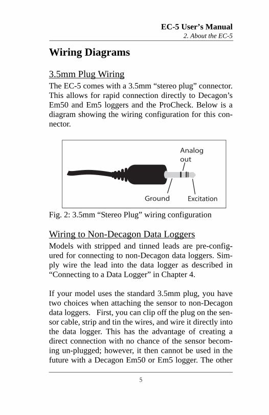
3.5mm Plug WiringThe EC-5 comes with a 3.5mm “stereo plug” connector.This allows for rapid connection directly to Decagon’sEm50 and Em5 loggers and the ProCheck. Below is adiagram showing the wiring configuration for this con-nector.
Fig. 2: 3.5mm “Stereo Plug” wiring configuration
Wiring to Non-Decagon Data LoggersModels with stripped and tinned leads are pre-config-ured for connecting to non-Decagon data loggers. Sim-ply wire the lead into the data logger as described in“Connecting to a Data Logger” in Chapter 4.
If your model uses the standard 3.5mm plug, you havetwo choices when attaching the sensor to non-Decagondata loggers. First, you can clip off the plug on the sen-sor cable, strip and tin the wires, and wire it directly intothe data logger. This has the advantage of creating adirect connection with no chance of the sensor becom-ing un-plugged; however, it then cannot be used in thefuture with a Decagon Em50 or Em5 logger. The other
Analog out
Ground Excitation
5

EC-5 User’s Manual2. About the EC-5
choice is to obtain an adapter cable from Decagon. The3-wire sensor adapter cable has a connector for the sen-sor jack on one end, and three wires on the other end forconnection to a data logger (this type of wire is oftenreferred to as a “pigtail” adapter). Both the sensor wireand adapter cable wire have the same wire output(shown in Fig. 3); the white wire is excitation, red isoutput, and the bare wire is ground.
Fig. 3: 3-wire cable wiring configuration
Extended cable lengthsDecagon recommends that you purchase customizedcable lengths if your project requires longer cable leads.Custom cable lengths may be requested with a 3.5mmconnector or stripped & tinned end.
Analog out (Red)
Ground (Bare)
Excitation (White)
Sensor cable
6

EC-5 User’s Manual3. Installing the Sensors
3. Installing the SensorsWhen selecting a site for installation, it is important toremember that the soil adjacent to the sensor surface hasthe strongest influence on the sensor reading and thatthe sensor measures the volumetric water content.Therefore any air gaps or excessive soil compactionaround the sensor can profoundly influence the read-ings. Also, do not install the sensors adjacent to largemetal objects such as metal poles or stakes. This canattenuate the sensor’s electromagnetic field andadversely affect output readings. Because the EC-5 hasgaps between its prongs, it is also important to considerthe size of the media you are inserting the sensor into. Itis possible to get sticks, bark, roots or other materialstuck between the sensor prongs, which will adverselyaffect readings. Finally, be careful when inserting thesensors into dense soil, as the prongs will break if exces-sive sideways force is used when pushing them in.
ProcedureWhen installing the EC-5, it is best to maximize contactbetween the sensor and the soil.
1. The EC-5 sensor was designed for easy installationinto the soil. After digging a hole to the desireddepth, push the prongs on the sensor into undis-turbed soil at the bottom of the hole or into the side-wall of the hole. Make sure that the prongs andblack overmolding are buried completely as shownbelow.
7

EC-5 User’s Manual3. Installing the Sensors
The sensor may be difficult to insert into extremely compact or dry soil. If you have difficulty inserting the sensor, try loosening the soil somewhat or wet-ting the soil. Never pound it in!
2. Carefully backfill the hole to match the bulk densityof the surrounding soil. Be careful not to bend theblack overmolding connecting the sensor to thecable.
To watch a video on proper installation of the sensor goto www.decagon.com/install.
OrientationThe sensor can be oriented in any direction. However,orienting the flat side perpendicular to the surface of thesoil will minimize effects on downward water move-ment.
Removing the SensorWhen removing the sensor from the soil, do not pull itout of the soil by the cable! Doing so may break inter-nal connections and make the sensor unusable.
8

EC-5 User’s Manual4. Collecting Data
4. Collecting Data
Data Logger RequirementsThe EC-5 sensor is designed to work most efficientlywith Decagon’s 5-channel Em5b, Em50, or ProCheckhandheld readout. All Decagon readout devices use a3.0V excitation.
The sensors however, may be adapted for use with otherdata loggers, such as those from Campbell Scientific,Inc., for example. The EC-5 requires an excitation volt-age in the range of 2 to 3.6 volts. The sensors producean output voltage that depends on the dielectric constantof the medium surrounding the sensor, and rangesbetween 10 and 50% of the excitation voltage. Any datalogger which can produce a 2.5 to 3.6V excitation withapproximately 10 millisecond duration and read a volt-level signal with 12-bit or better resolution should becompatible with the EC-5 sensor. The current require-ment for the EC-5 is 10mA at 2.5V.
NOTE: EC-5 sensors are intended only for use withdata loggers and readout devices which can provideshort excitation pulses, leaving the sensors turned offmost of the time. Continuous excitation not only wastesbattery power, but may, under certain circumstances,cause the sensor to exceed government specified limitson electromagnetic emissions. Do not continuouslypower the EC-5 sensor.
9

EC-5 User’s Manual4. Collecting Data
Connecting to a Data LoggerConnect the wires to the data logger as shown, with thesupply wire (white) connected to the excitation, the ana-log out wire (red) to an analog input, and the bareground wire to ground:
Fig. 5: Data logger configuration
Sample ProgramThe following program is an example that can be usedwith Campbell Scientific’s CR10X data logger and ourEC-5 sensor at a 2500mV excitation:
;{CR10X}; Example ECH2O Data Logger Program for CR10X
; Wiring:
; White: Excitation Channel 1; Red: Input Single Ended Channel 1; Black: Ground
*Table 1 Program
Exc. H L G
Supply Analogout Ground
Data Logger
a o g
Exc. H L G
SupplyAnalog
out Ground
Data Logger
AnalogIn
10

EC-5 User’s Manual4. Collecting Data
01: 1 Execution Interval (seconds)
; Factory calibration equations for ECH2O; probes convert mV output of ECH2O to; volumetric water content (VWC, m3/m3)
; EC-5: VWC = 0.00119 * mV - 0.400
1: Excite-Delay (SE) (P4) 1: 1 Reps 2: 5 2500 mV Slow Range 3: 1 SE Channel 4: 1 Excite all reps w/Exchan 1 5: 1 Delay (0.01 sec units) 6: 2500 mV Excitation 7: 1 Loc [ Probe_VWC ] 8: .00119 Multiplier 9: -.4 Offset
*Table 2 Program 02: 0.0000 Execution Interval (seconds)
*Table 3 Subroutines
End Program
SCWin (Short Cut) DirectionsThe following are instructions for using Campbell Sci-entific’s SCWin (Short Cut) program to read the EC-5soil moisture sensor.
1. Download EchoCSI.zip from http://www.deca-gon.com/appnotes/EchoCSIappnote.pdf.
2. Unzip the folder EchoCSI.zip.
3. Locate the file containing SCWin.exe. It should bein C:\Program Files\Campbellsci\SCWin. Place the
11

EC-5 User’s Manual4. Collecting Data
following files from the unzipped EchoCSI.zipfolder into the folder with SCWin.exe:
AM1632Z.MUXAM416Z.MUXEC10.SCSEC101632.SCSEC10416.SCSEC20.SCSEC201632.SCSEC20416.SCSEC5.SCSEC5632.SCSEC5416.SCSSCWIN-DECAGON.CNTSCWIN-DECAGON.HLP
Note: If you are not able to find this directory path,search for the folder that contains SCWIN.exe and placethe files into that folder.
4. Open up SCWin.exe (Short Cut). If you are using aV.3 copy of LoggerNet, there is a tab for SCWin(Short Cut) on the tool bar.
5. Select “New” to start a new program to read the EC-5.a. Select the data logger you will be using to read thesensors.b. Select the measurement interval (a shorter measure-ment interval, i.e. 1 sec., is sometimes desirable whentesting the sensor).
6. Click on Sensors (this should open a new page witha file tree on it).
12

EC-5 User’s Manual4. Collecting Data
7. Under the “Sensors” file tree, double-click on“Meteorological” and then select “Soil Moisture.”
8. Choose “EC-5” Sensor.
CalibrationDecagon’s ECH2O Utility, and DataTrac3 automaticallyapply factory calibrations to the sensors’ output data.However, this general calibration may not be applicablefor all soil types. For added accuracy we encourage ourcustomers to perform soil-specific calibrations.
The calibration equation that you will use depends onwhere you will be using it. If you will be using it withsensors connected to a non-Decagon data logger youwill need to use the 2500 mV calibration. If you use anyDecagon software (DataTrac3, ECH2O Utility, etc.) orthe user calibration menu in the ProCheck, you willneed to use the RAW calibration. The differencebetween the two is the slope constant. To increase theresolution of the sensor output, Decagon uses all avail-able increments of the 12-bit number (value of 4096)where the measurement is stored. Thus, the output of thesensors read by the ProCheck and Decagon loggersmust be multiplied by 0.61 AND the 2500 mV slope togive the right value.
Sensor Calibration ValuesFollowing is a list of the both the millivolt and RAWcalibration values for the EC-5, where is the volumet-ric water content, mV is the millivolt output of the sen-sor, and where x is the RAW sensor output.
13

EC-5 User’s Manual4. Collecting Data
The EC-5 is much less sensitive to variation in textureand electrical conductivity because it runs at a muchhigher measurement frequency. Therefore, its generalcalibration equation should apply for all mineral soils upto 8 dS/m saturation extract. Its calibration equations areshown below for mineral soil, potting soil, and rock-wool growing media:
Dielectric PermittivityDielectric permittivity can be used to determine volu-metric water content using external published equationssuch as the Topp equation. Dielectric permittivity isgiven by
= 1/(-1.1x 10-9RAW3 x 10-6RAW2x 10-3 RAW
where RAW is the output from the Decagon data loggerusing 3V excitation. If you are using a non-Decagondata logger, dielectric permittivity is given by
= 1/(x 10-9mV3 x 10-6mV2
x 10-3 mV
Mineral SoilsAccording to our tests, a single calibration equation willgenerally suffice for all mineral soil types with electricalconductivities from 0.1 dS/m to 10 dS/m saturationextract. Volumetric water content (ø) is given by
ø = 8.5 * 10-4 * RAW - 0.48 (1)
14

EC-5 User’s Manual4. Collecting Data
where RAW is the output from the Decagon data loggerusing 3V excitation. If you are using a non-Decagondata logger, VWC is given by
ø = 11.9 * 10-4 * mV - 0.401 (2)
where mV is the output of the sensor when excited at2500 mV. Please note that the equation will reach amaximum at ~60% volumetric water content (VWC) inpure water. To display data on a scale from 0 to 100%,VWC should be modeled with a quadratic equation(which would result in a 100% VWC in water), but alinear equation fits the mineral soil VWC range as wellas the quadratic, and linear equations are easier to dealwith, especially since mineral soil typically saturates at~40 - 50% VWC.
Potting soilThe following equations can be used to convert EC-5output to water content in potting soil. We tested severaltypes of potting soil (Sunshine mix, Miracle Grow Pot-ting Mix, and Custom Nursery soil) at several salinitiesand found that VWC is given by
ø = 1.3 * 10-3 * RAW - 0.696 (3)
for a Decagon data logger or
ø = 2.11 * 10-3 * mV - 0.675 (4)
for a data logger with 2500mV excitation.
15

EC-5 User’s Manual4. Collecting Data
RockwoolThe EC-5 was calibrated in Grodan Master rockwoolwith solution electrical conductivities of 0.2, 1.0, 1.5,2.0, and 4.5 dS/m. Volumetric water content can be cal-culated using
ø = 6.28 * 10-7 * RAW2 + 1.37 x 10⁻⁴ * RAW - 0.183(5)
for a Decagon data logger or
ø = 2.63 * 10-6 * mV2 + 5.07 x 10⁻⁴ * mV - 0.0394(6)
for a data logger with 2500 mV excitation.
NOTE: These calibration constants only apply to2500mV excitations; use of these numbers with any otherexcitation voltage will result in erroneous readings!
TroubleshootingIf you encounter problems with the EC-5, they mostlikely will manifest themselves in the form of incorrector erroneous readings. Before contacting Decagon aboutthe sensor, do the following:
• Check to make sure the connections to the data logger are both correct and secure.
• Ensure that your data logger’s batteries are not dead or weakened.
If you encounter problems that aren’t due to the datalogger, please contact Decagon at (509) 332-5600 or [email protected].
16
EC-5 User’s ManualDeclaration of Conformity
Declaration of Conformity
Application of Council Directive: 89/336/EE6
Standards to which conformity EN61326 : 1998is declared: EN51022 : 1998
Manufacturer’s Name: Decagon Devices, Inc. 2365 NE Hopkins Court Pullman, WA 99163 USA
Type of Equipment: Soil moisture sensor
Model Number: EC-5
Year of First Manufacture: 2001
This is to certify that the EC-5 ECH2O soil moisturesensor, manufactured by Decagon Devices, Inc., a cor-poration based in Pullman, Washington, USA meets orexceeds the standards for CE compliance as per theCouncil Directives noted above. All instruments arebuilt at the factory at Decagon and pertinent testing doc-umentation is freely available for verification.
17

EC-5 User’s ManualDeclaration of Conformity
18

EC-5 User’s ManualIndex
IndexAAccuracy 1
CCalibration 13
for mineral soil 14for potting soil 15for rockwool 16
Customer support 2
DData logger 1
connecting to 10requirements 9sample program 10
Declaration of conformity 17Dielectric permittivity 14
EE-mail 2Extension cables 6
FFax 2
IInstallation 7
MMeasurement range 1Mineral soil
calibration 14
19

EC-5 User’s ManualIndex
OOrientation of sensor 8
PPhone number 2Plug wiring configuration 5Potting soil 15Power requirements 1Program 10
RRange 1Removing sensor 8Rockwool 16
SSeller’s liability 2Sensor
calibration 13installation instructions 7orientation 8specifications 1
Short cut directions 11Specifications 1
TTroubleshooting 16
WWarranty 2Wiring diagrams 5
20