soil mechanics surface sampler: lunar surface tests...
TRANSCRIPT

JOURNAL OF GEOPHYSICAL RESEARCH VoL. 73, No. 12. JuNv, 15. 1968
Soil Mechanics Surface Sampler: Lunar Surface Tests, Results, and Analyses
R. F. SCOTT 1 AND F. I. ROBERSO• '2
After the success of Surveyor 1 in meeting the objectives of the engineering flight series, selection from among candidate experiments led to the inclusion of the soil mechanics surface sampler (SMSS) on the Surveyor 3 payload. Altho.ugh originally planned for later Survey. ors, the SMSS was modified to fit the red. uced telemetry and commanding capability of Surveyor 3. Specifically, the SMSS was adapted to the mounting location and the elec- tronics interface of the approach television camera. This required a concentrated, short-term effort to modify, btfild, and test the SMSS to meet the demanding interface requirements. Modifications to the SMSS included removal of the strain-, acceleration-, and position-meas- uring systems originally planned and incorporation of a means for measuring current drawn by the motors during operation. A description of the modified device, its performance on Surveyor 3, and some conclusions about the lunar surface material are presented in this paper.
SUBSYSTEM I)ESCRIPTION
The SMSS subsystem consists of a mecha- nism, an electronics auxiliary, an installation substructure, and wiring harnesses. The mecha- nism is an electromechanical device that can
pick, dig, scrape, and trench the lunar surface and transport lunar surface material [Scott, 1967]. The electronics auxiliary provides com- mand decoding, data buffering, power manage- ment, squib firing, and control of the mecha- nism, motors, and clutch. The installation substructure supports the mechanism and the auxiliary on the spacecraft. The wiring har- nesses provide the electrical interconnections with the spacecraft and between units within the subsystem.
Extension-retraction mechanism. The exten-
sion-retraction mechanism is designed to sup- port and position the scoop and to permit operations within the space envelope shown in Figure 1. The mechanism rotates about azi- muth and elevation pivot points to provide movement in spherical coordinates.
Drive system. Three electrical motors, oper- ating through appropriate drive trains, furnish mechanical energy to manipulate the SMSS in extension and retraction, azimuth, and eleva- tion. At command from earth, an electrome-
• California Institalte of Technology, Pasadena, California 91109.
'Jet Propulsion Laboratory, California Insti- tute of Technology, Pasadena, California 91103.
chanical clutch disengages the elevation drive train; the mechanism is impelled downward by a pretensioned elevation torque .spring and strikes the lunar surface. A fourth electric
motor opens and closes the scoop. The motors and clutch draw electrical power from the spacecraft unregulated bus through the elec- tronics auxiliary, which also provides switch control.
Scoop. The scoop consists of a container, a sharpened blade, and an electrical motor to open and close the container. A small footpad is attached to the scoop door to present a flat surface to the lunar surface. The maximum
size of solid lunar material the scoop can hold is approximately 3.2 cm in diameter; the maxi- mum amount of granular material that can be held is 100 cm •.
Before the Surveyor 3 flight, a test of SMSS motor current versus force calibration was per- formed on the spacecraft at Cape Kennedy under ambient temperature conditions and at an unregulated voltage of 22 volts. The pur- pose of this test was to acquire information about mechanical properties of the lunar sur- face from motor current measurements during SMSS operations on the landed spacecraft.
Motor control. Either a 2-se½ or a 0.1-see
period of operation of any of the motors can be selected by earth command. The angle or distance through which the SMSS moves by these commands depends on the motor involved, its condition, temperature, voltage, and the working load.
4045
4046 SCOTT AND ROBEPSON
+Y
SPACECRAFT AXIS -,--60.9 cm (REF)• SPACECRAFT AXIS AZIMUTH +X i74cm (REF) _•__•..•'• PIVOT AXIS -y'
i. •,•,•/•"58.'4• L•-•_• STOWED POSITION
' 147 (',m R
2 OF SCOOP • AZIMUTH AXIS • • • 10.9 cm (REF)
._,, y PIVOT AXIS
, _ , SURFnC•_
• VIEW A-A
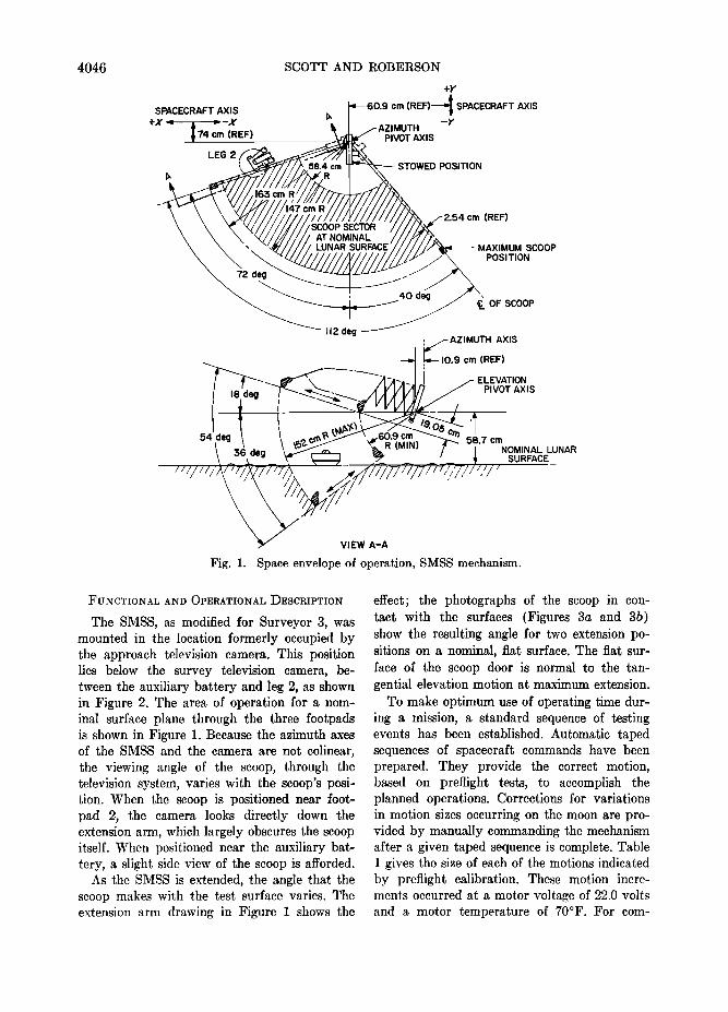
Fig. 1. Space envelope of operation, SMSS mechanism.
FUNCTIONAL AND OPERATIONAL •)ESCRIPTION
The SMSS, as modified for Surveyor 3, was mounted in the location formerly occupied by the approach television camera. This position lies below the survey television camera, be- tween the auxiliary battery and leg 2, as shown in Figure 2. The area of operation for a nom- inal surface plane through the three footpads is shown in Figure 1. Because the azimuth axes of the SMSS and the camera are not colinear, the viewing angle of the scoop, through the television system, varies with the scoop's posi- tion. When the scoop is positioned near foot- pad 2, the camera looks directly down the extension arm, which largely obscures the scoop itself. When positioned near the auxiliary bat- tery, a slight side view of the scoop is afforded.
As the SMSS is extended, the angle that the scoop makes with the test surface varies. The extension arm drawing in Figure I shows the
effect; the photographs of the scoop in con- tact with the surfaces (Figures 3a and 3b) show the resulting angle for two extension po- sitions on a nominal, fiat surface. The fiat sur- face of the scoop door is normal to the tan- gential elevation motion at maximum extension.
To make optimum use of operating time dur- ing a mission, a standard sequence of testing events has been established. Automatic taped sequences of spacecraft commands have been prepared. They provide the correct motion, based on prefiight tests, to accomplish the planned operations. Corrections for variations in motion sizes occurring on the moon are pro- vided by manually commanding the mechanism after a given taped sequence is complete. Table 1 gives the size of each of the motions indicated by prefiight calibration. These motion incre- ments occurred at a motor voltage of 22.0 volts and a motor temperature of 70øF. For com-

SURVEYOR 3--SOIL MECIIANICS SURFACE SAMPLER
PLANAR ARRAY ANTENNA ,SOLAR PANEL'
OMNIDIRECTIONAL ANTENNA A
4047
SURVEY TV CAMERA
OMNIDIRECTIONAL ANTENNA B
LEG I
LEG 3
TANK
BATTERY
SMSS EXTENDED
LEG 2 SHOCK ABSORBER
TV TARGET
•FOOTPAD 2
Fig. 2. Surveyor spacecraft, sho.wing SMSS mo.unted at approach camera location.
- •i-......._-•-.-... -.-_..-:...•.. -•%:: -::?• .................. ::::::::::::::::::::::::: .... i' :iii?•?•::::•i•:•i!i!i!i:--:-'----:,•: .................. .... ."•:i•i::',i',iiiiiiiiii??...'_--iii...•_.:i .......... •i•i ............... ?..-:•...::•i•i•--:-':.-':•:--•:•:•::•:"ii•:?,iiiiiiii :•............•`•!•.:i•i!i!......iiiii:......:..:.•ii•..:.:...:.?:.:•......:•
.... ::::: .................... ::::::::::::::::::::::::::::::::::::::: ..... .......
.....
.i:;"•,"•":;-;•:•.J --- :;;•.•. - •:::-;•i.•:•;•:•.:..:•,..:::i:::: ....•:•:.i::::::i:::•.•- .. •+.• -.•::.......:.::::-::::::.• . - ........... :::::: .............. -:.:-..
ß ' ::'• •' •;•: "..• ' ..o'"-• ..... •:•:•:!•i•:•ii•;•::_.::: ;:i ...... •;. ..---•.• .,-. •. •:.• . .:. . . -....: f ,.-•;•:• •.i.• • •,:•. .• .!..•,.: ,^:.•. . .. . ...:,.• ...•..:.•.•.:•-.•... •:.-!.
Fig. 3. Pho•.ographs showing angle that SMSS scoop door makes with a nominal surface at (a) maximum extension distance and (b) minimum extension distance at which surface can be reached.

4048 SCOTT AND ROBERSON
TABLE 1. SMSS Motion Increments (No Load)
Motion Time, see Nominal Test Value*
Value on Lunar Surface, Preliminary Estimate from
TV Observation
Value on Lunar Surface, from Comparison of
Model and Spacecraft Functionsi
2.0 (extend) 8.6 cm 4.4 cm 2.5 cm 2.0 (retract) 8.1 cm 3.8 cm 2.2 cm 0.1 (right azimuth) 1.5 ø 1.5 ø 2.3 ø 0.1 (left azimuth) 1.5 o 1.5 o 2.5 o 2.0 (up) 6 o 6 o 12 o 2.0 (down) 9 ø 9 ø 12 ø
* Based on unit and system level tests at three extension distances. • Based on SETL tests using full-scale model spacecraft and television system. Comparison made with
day-111 SMSS operations on lunar surface.
parison, the sizes of motion increments esti- mated during Surveyor 3 lunar operations also are given. More precise calibrations will be made at a later time.
The originally planned initial standard se- quence of tests included six static bearing tests and a single trenching operation. Provisions were made for performance of optional tests, based on decisions made during lunar oper- ations. Such optional tests were to include im- pact tests, picking up rocks, trenching deeper, and bearing tests on subsurface material.
A static bearing test is performed by exer- cising the extension and azimuth motions until the scoop is positioned above the desired sur- face point. Then, with the scoop door closed to provide the fiat surface for contact, the scoop is driven downward with the elevation motor until the desired penetration is achieved, or until the motor is stalled. An open-scoop static test can also be conducted.
For an impact test the scoop is again posi- tioned above the desired surface point. The elevation drive clutch is actuated, allowing the scoop to drop to the surface, accelerated by gravity and the torque spring attached at the elevation axis. An impact test can be performed with the scoop open or closed.
A trenching operation is performed by driving the scoop down into the surface with the door open, then drawing the scoop toward the space- craft with the retraction motor. Material can
be removed from the trench by retracting the scoop until it is clear of the surface, forming a pile of soil at the foot of the trench, or by
closing the scoop and lifting the material out of the trench.
Because position-indicating telemetry is not available, the operations of the SMSS experi- ment must be monitored closely by the survey television camera. Sequences and priorities for tests, therefore, depend on viewing conditions, spacecraft shadow patterns, and the perform- ance of the television system.
MISSION ]DESCRIPTION
SMSS Engineering Performance
The SMSS electronics auxiliary was initially turned on, on day 111; operations were con- cluded on day 122.
During the 18 hr, 22 min of total on time for the SMSS auxiliary in the first lunar day, 5879 spacecraft commands were transmitted to it. All commands were correctly coded, and 1898 SMSS commands were generated. The SMSS and its electronics auxiliary responded correctly to each command throughout this period.
After touchdown it was found that .some of
the Surveyor 3 telemetry was not reliable, so that no valid SMSS motor current data could
be obtained. The forces applied to the lunar surface by the SMSS had to be estimated from the measured characteristics of the motors
when stalled.
Lunar Surface Operations
Late in Goldstone view period of day 111, it was determined that the temperature of the SMSS electronics auxiliary was high enough

SURVEYOR 3--SOIL MECHANICS SURFACE SAMPLER 4049
for operation. The decision to turn on the SMSS power was followed by a short series of tests to assess the condition of the electronics and to attempt a solution of the spacecraft telemetry problems. This section will briefly describe SMSS operations on and after day
111. The locations of all tests are shown in
Figure 4. Day 111. Initial operations began accord-
ing to the standard sequence and included fir- ing of the pyrotechnic locking device (to re- lease the SMSS from its stored position) and
• IMPACT r'-m BEARING C) CONTACT
A BEARING TEST I L BEARING TEST 4 V BEARING TEST 7 B TRENCH I M IMPACT TEST I W IMPACT TEST 7 C TRENCH 2 N IMPACT TEST 2 X IMPACT TEST 8 D CONTACT I 0 IMPACT TEST 3 Y IMPACT TEST 9 E BEARING TEST 2 P IMPACT TEST 4 Z IMPACT TEST I0 F BEARING TEST 3 Q IMPACT TEST 5 o CONTACT 4 G TRENCH $ R IMPACT TEST 6 b IMPACT TEST II H CONTACT 2 S BEARING TEST 5 c IMPACT TEST 12 I FOOTPAD CONTACT T CONTACT 3 d TRENCH 4 J TRENCH 3 WIDEN U BEARING TEST 6 e IMPACT TEST 13 K TRENCH 3 WIDEN
•,'• ['EXTENSION '- 140 cm
cm %• • • •f •ELEVATION= •
•ELEVATION +8 cm
TV CAMERA
FOOTPAD 2:
Fig. 4. Plan view of SMSS area of operations, showing location of all surface tests per- formed during first lunar day of Surveyor 3 mission. Angles are referenced to SMSS axis in stowed position. Extension distance is measured from scoop tip to elevation axis of SMSS; elevation is measured relative to a fiat plume through the bottom of the three footpads.

4050 SCOTT AND ROBERSON
transmission of four commands to extend the and positioned above the surface near the apparatus. A television picture to verify oper- auxiliary battery to prepare for the first static ation of the extension motor showed that ex- bearing test. tension had occurred but that the extended The Goldstone view period ended as the distance was less than expected. bearing test sequence was being initiated;
The sequence of four commands was re- consequently, the SMSS scoop did not contact peated, and television verified that the SMSS the surface. The final position of the deployed scoop had then reached the originally intended mechanism on day 111 is shown in Figure 5. position. A standard sequence that included Day 112. It had been intended at the end various commands to extend; to retract; and of day 111 operations to perform the first bear- to move right, le/t, up, and down was next ing test on day 112 at the final day 111 post- initiated. Completion of these motions showed tion of the SMSS. Before further SMSS oper- that other SMSS motors had operated as speci- ations on day 112, television surveys were fled. The scoop door motor and the clutch conducted, including a narrow-angle survey of actuator were not tested at this time. the SMSS operations area. I)uring the tele-
Glare in the television optical system, re- vision operations, however, problems occurred sulting from sun angle, had prevented acom- in azimuth stepping at a time when the camera plete television survey of the area of SMSS was stepping clockwise, or to the right azimuth. operations. Because narrow-angle coverage was Accordingly, it was decided to move the SMSS available only for the area near the auxiliary into the field of view of the television camera battery, it was decided to depart from the and to start testing the lunar surface. The standard sequence. The scoop was extended surface was located and a command was sent
..•..... , .-. -. w --'..:':. ;-
.... ';.}.....,;•.';:;..;; .... -,; .:. •-: .. ..... .. •. '":. .?
--.•....
.--, ..... • . .. -....... ß ,.... . ... ..... . .... .-.
.....' ..................... ..
: .:.....:?-. •:: -.•
Fig. 5. SMSS deployed. and ready fo.r bearing test as Goldstone view ended on April 21 1967 (day 111, 10h 43m 30s GMT).
SURVEYOR 3--SOIL MECHANICS SURFACE SAMPLER
•...•:• ,.. .• • . .. •.•.• ß •...• .... ..•. •-. ,. ...... ...•.•
.
::
'i
!:
.:
ß
ß
4051
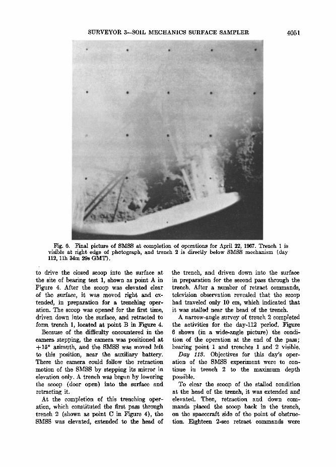
Fig. 6. l•'in•l picture of SMSS at completio.n of operations for April 22, 1967. Trench 1 is visible •t right edge of photograph, a•nd trench 2 is directly below SMSS mechanism (day 112, 11h 34m 29s GMT).
to drive the closed scoop into the surface at the site of bearing test 1, shown as point A in Figure 4. After the scoop was elevated clear of the surface, it was moved right and ex- tended, in preparation for a trenching oper- ation. The scoop was opened for the first time, driven down into the surface, and retracted to form trench 1, located at point 13 in Figure 4.
13ecause of the difficulty encountered in the camera stepping, the camera was positioned at +15 ø azimuth, and the SMSS was moved left to this position, near the auxiliary battery. There the camera could follow the retraction
motion of the SMSS by stepping its mirror in elevation only. A trench was begun by lowering the scoop (door open) into the surface and retracting it.
At the completion of this trenching oper- ation, which constituted the first pass through trench 2 (shown as point C in Figure 4), the SMSS was elevated, extended to the head of
the trench, and driven down into the surface in preparation for the second pass through the trench. After a number of retract commands, television observation revealed that the scoop had traveled only 10 cm, which indicated that it was stalled near the head of the trench.
A narrow-angle survey of trench 2 completed the activities for the day-112 period. Figure 6 shows (in a wide-angle picture) the condi- tion of the operation at the end of the pass; bearing point I and trenches I and 2 visible.
Day 113. Objectives for this day's oper- ation of the SMSS experiment were to con- tinue in trench 2 to the maximum depth possible.
To clear the scoop of the stalled condition at the head of the trench, it was extended and elevated. Then, retraction and down com- mands placed the scoop back in the trench, on the spacecraft side of the point of obstruc- tion. Eighteen 2-see retract commands were

4052 SCOTT AND ROBERSON
/';: ..a... ...... .7. ...... :- *::;•, ",; '"%.:.,½ ....... '" ....-.s
.....
:,:•.... ß •;;.. ....-;,:. :z/:;...:...,. ...
.:.,..;•;-: .. ;,•.. -,,.•':.;,, . ,•4. -::::,7.•....
.... ß ***,**.•-:.,....
•.• .
Fig. 7. Wide-angle view of SMSS and footpad 2 (April 26, 1967). Note pile of lunar surface material on top of footpad (day 116, llh 53ra 26s GMT).
transmitted; after a television survey twelve Day 11J. A survey of trench 2 was the only additional transmissions, a sequence of retrac- operation performed on day 114 that was re- tion commands, completed the second pass lated to SMSS. Solar eclipse studies were through trench 2. made.
A television survey of the trench preceded Day 115. High temperatures precluded repositioning of the scoop to the head of the SMSS operations during this Goldstone view trench in preparation for the next drag. The period. scoop was driven down, again at the head of Day 116. It was decided to restrict SMSS the trench, and a series of retraction com- operations to the area near footpad 2 to avoid mands was given to complete the third pass unnecessary stepping of the television camera through the trench. Television observation mirror. showed the scoop traveled less than in the A study of pictures from the day-113 sur- previous trenching pass, indicating loading at vey of trench 2 revealed a solid object (con- the limit of its retraction capacity. The Gold- tact 1, point I), in Figure 4), possibly a rock, stone view period ended with narrow-angle directly beneath the scoop in its last position. television surveys of the trench and the SMSS Some experiments with a full-scale model space- in position at the foot of trench 2. craft with an SMSS attached provided a work-

SURVEYOR 3--SOIL MECHANICS SURFACE SAMPLER 4053
able sequence of commands to pick up the object without the aid of television, because the camera position precluded narrow-angle viewing of the scoop. The scoop was visible in wide-angle television without violating the stepping constraint. Operations for day 116 began with this sequence, which resulted in closing the scoop door on the object.
Elevation of the scoop revealed that the object had apparently been crushed while being retrieved. It was decided, however, to place the material in the scoop on the surface of footpad 2. The SMSS was extended, rotated right, and viewed through the television system. Because of an uncertainty in the precise extension dis- tance, the scoop was moved left, clear of the footpad, and lowered to the surface, to make
a mark indicating its position. After elevating the scoop clear of the surface, study of the mark indicated further extension was required. The extension was performed, and the scoop was moved to make contact with the top of footpad 2. The scoop door was opened; the scoop was elevated and lowered to jar loose the material. The scoop was moved up and to the left to clear the television view of the
footpad. The position of the SMSS at the end of the operation and the surface material on the footpad are shown in Figures 7 and 8. A narrow-angle color-filter survey of the mate- rial was conducted before the end of the Gold-
stone view.
Day 117. Operations on day 117 consisted of moving left from footpad 2 and extending
;Fig. 8. Material dumped on footpad 2 bv SMSS (April 26, 1967). The color cMibration chart is in foreground (day 116, 12h 00m 54s GMT).

4054 SCOTT AND ROBERSON
Fig. 9. Wide-angle view of SMSS at end of April 2'7, 1967, operations. Trench 3 and bearing test 2 are visible on the surface (day 117, 10.h 34m 53s GMT).
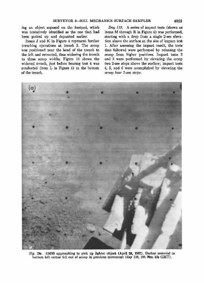
the SMSS. Bearing test 2 was then performed. ing the scoop, with the door open, over the Bearing test 3 was performed next after moving object (Figure 10). With close coordination the SMSS farther right with a greater exten- between narrow-angle television viewing and sion. These two bearing tests are located at SMSS commanding, the object was picked up points E and F in Figure 4. in the scoop.
The SMSS scoop was positioned left and After positioning the scoop over footpad 2, driven into the surface with the scoop open; and opening the scoop door, a short series of trench 3 was started. This trench, shown at G 0.1-sec elevate and lower commands was issued in Figure 4, was dug by retracting the SMSS to ensure that the object had been shaken loose in the 2-sec mode, a total of twenty-six steps. from the scoop. This motion freed a portion of A special series of twenty-six television pic- soil that had remained in the scoop since the tures was taken during this trenching oper- previous trenching operation. Subsequent tele- ation, one frame after each retraction step. vision observation of the footpad showed the Figure 9 shows the completed trench 3 and pile of material that had been shaken loose, bearing point 2. which apparently had fallen onto and covered
Day 118. At the close of SMSS operations the deposited object. on day 117, an object of higher albedo than Attempts were made to uncover the object the surrounding surface was observed near by placing the scoop tip on the footpad and trench 3, at contact point 2 (item H in Fig- retracting it. This action succeeded in remov- ure 4). Operations for day 118 began by plac- ing some material from the footpad and leav-
SURVEYOR 3--SOIL MECHANICS SURFACE SAMPLER 4055
ing an object exposed on the footpad, which was tentatively identified as the one that had been picked up and deposited earlier.
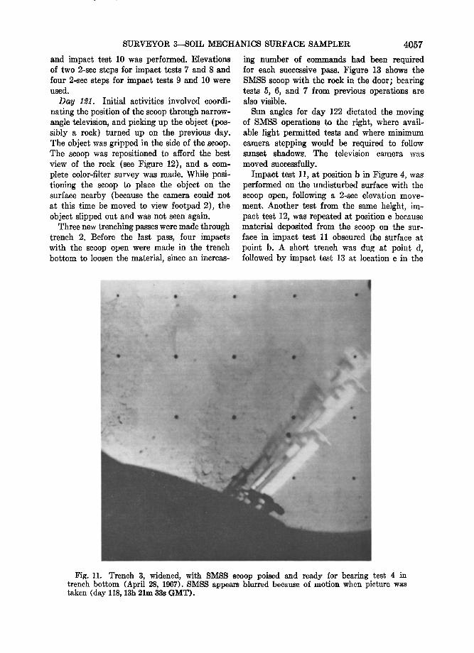
Items J and K in Figure 4 represent further trenching operations at trench 3. The scoop was positioned near the head of the trench to the left and retracted, thus widening the trench to three scoop widths. Figure 11 shows the widened trench, just before bearing test 4 was conducted (item L in Figure 4) in the bottom of the trench.
Day 119. A series of impact tests (shown as items M through R in Figure 4) was performed, starting with a drop from a single 2-sec eleva- tion above the surface at the site of impact test 1. After assessing the impact result, the tests that followed were performed by releasing the scoop from higher positions. Impact tests 2 and 3 were performed by elevating the scoop two 2-sec steps above the surface; impact tests 4, 5, and 6 were acomplished by elevating the scoop four 2-sec steps.
Fig. 10a. $MSS approaching to pick up lighter object (April 28, 1967). Darker material in bottom left corner fell out of scoop in previous movement (day 118, 10h 20m 10s GMT).
4056 SCOTT AND ROBERSON
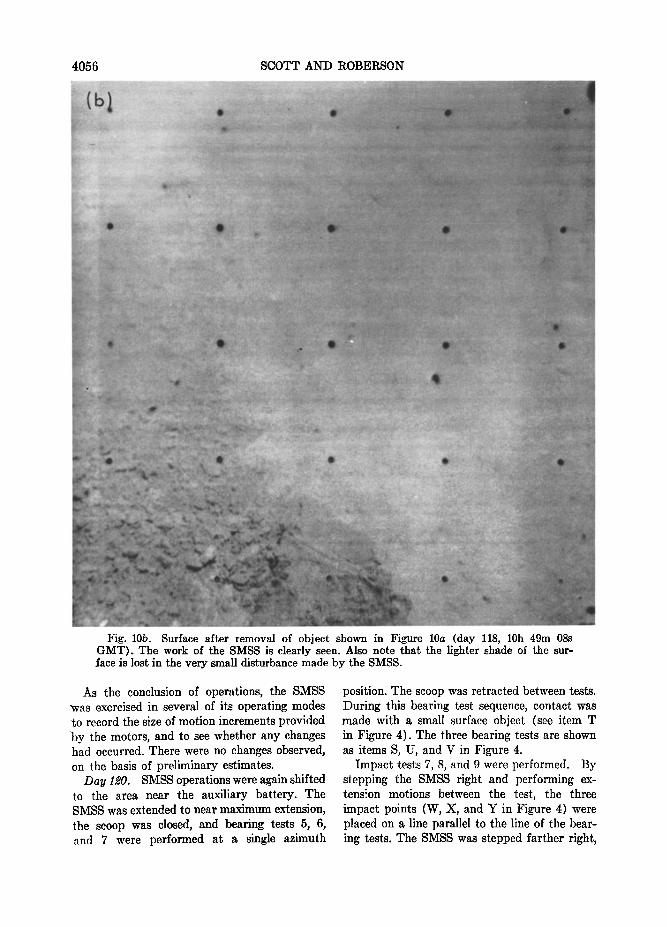
Fig. 10b. Surface after removal of object shown in Figure 10a (day 118, 10h 49m 08s GMT). The work of the SMSS is clearly seen. Also note that the lighter shade of the sur- ,face is lost in the very small disturbance made by the SMSS.
As the conclusion of operations, the SMSS •vas exercised in several of its operating modes -to record the size of motion increments provided by the motors, and to see whether any changes had occurred. There were no changes observed, on the basis of preliminary estimates.
Day 120. SMSS operations were again shifted to the area near the auxiliary battery. The SMSS was extended to near maximum extension, the scoop was closed, and bearing tests 5, 6, and 7 were performed at a single azimuth
position. The scoop was retracted between tests. During this bearing test sequence, contact was made with a small surface object (see item T in Figure 4). The three bearing tests are shown as items S, U, and V in Figure 4.
Impact tests 7, 8, and 9 were performed. By stepping the SMSS right and performing ex- tens!on motions between the test, the three impact points (W, X, and Y in Figure 4) were placed on a line parallel to the line of the bear- ing tests. The SMSS was stepped farther right,
SURVEYOR 3--SOIL MECHANICS SURFACE SAMPLER 4057
and impact test 10 was performed. Elevations of two 2-see steps for impact tests 7 and 8 and four 2-scc steps for impact tests 9 and 10 were used.
Day 121. Initial activities involved coordi- nating the position of the scoop through narrow- angle television, and picking up the object (pos- sibly a rock) turned up on the previous day. The object was gripped in the side of the scoop. The scoop was rcpositioned to afford the best view of the rock (see Figure 12), and a com- plete color-filter survey was made. While posi- tioning the scoop to place the object on the surface nearby (because the camera could not at this time be moved to view footpad 2), the object slipped out and was not seen again.
Three new trenching passes were made through trench 2. Before the last pass, four impacts with the scoop open were made in the trench bottom to loosen the material, since an incrcas-
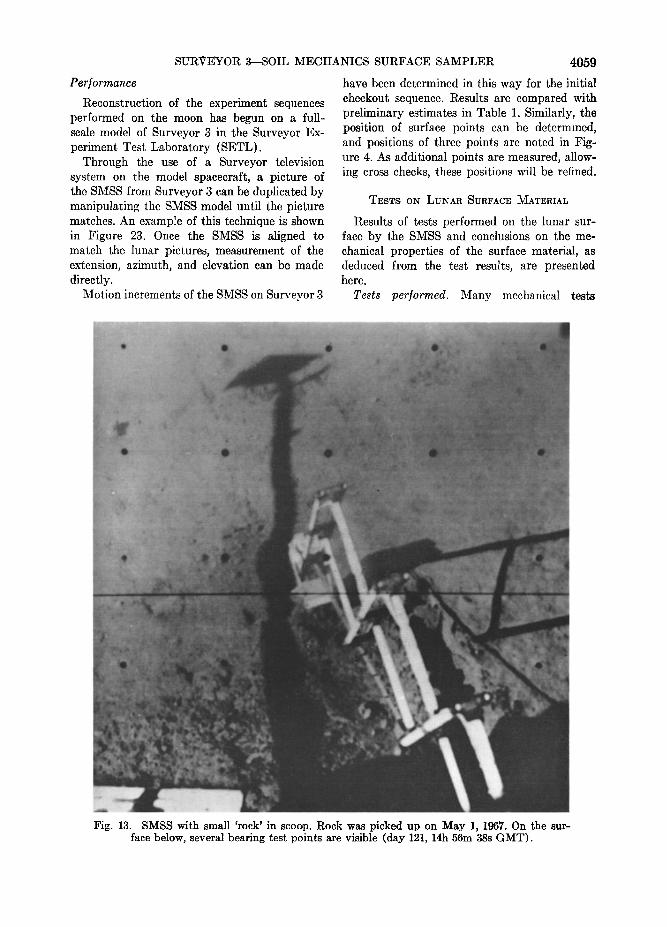
ing number of commands had been required for each successive pass. Figure 13 shows the SMSS scoop with the rock in the door; bearing tests 5, 6, and 7 from previous operations are also visible.
Sun angles for day 122 dictated the moving of SMSS operations to the right, where avail- able light permitted tests and where minimum camera stepping would be required to follow sunset shadows. The television camera was
moved successfully'. Impact test 11, at position b in Figure 4, was
performed on the undisturbed surface with the scoop open, following a 2-sec elevation move- ment. Another test from the same height, im- pact test 12, was repeated at position c because material deposited from the scoop on the sur- face in impact test 11 obscured the surface at point b. A short trench was dug at point d, followed by impact test 13 at location e in the
Fig. 11. Trench 3, widened, with SMSS scoop poised and ready for bearing test 4 in trench bottom (April 28, 1967). SMSS appears blurred because: oœ motion wher• picture was taken (day 118, 13h 21m 33s GMT).

4058 SCOTT AND ROBERSON
Fig. 12. Close-up picture of 'rock' extracted from lunar surface and being held by SMSS on May 1, 1967 (day 121, 15h 18m 39s GMT).
trench bottom on subsurface lunar material.
The final position of the SMSS, with trench 4 and several impact points visible on the surface below, is shown in Figure 14.
Operations are summarized in Table 2. A television picture mosaic (Figure 15) shows the area and results of operations in trench 1 (Fig- ure 4, item 13).
In summary, the second trench, which was along an azimuth line that facilitated camera coverage, was worked on three separate Gold- stone view periods (Table 2). The progress of trench formation is shown in television picture mosaics. Figure 16 shows the area before trench- ing operations began. The initial pass ended in
the condition shown in Figure 17. On the second pass, the SMSS scoop was extended slightly beyond the end of the first trench (Figure 18), and the subsequent series of retract commands resulted in a short travel (Figure 19). During day 113, the SMSS was removed from its posi- tion in the second trench (Figure 4, item C) and a trench survey was performed (Figure 20). Two additional trench attempts resulted in the formation of the trench to the condition shown
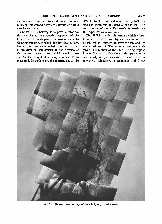
in Figure 21, a survey performed during day 114. Figure 22 is a general area survey showing trench 2 under lighting conditions of day 120. It should be noted that additional work was
done in trench 2 on day 121.
SURVEYOR 3--SOIL MECHANICS SURFACE SAMPLER 4059
Performance
:Reconstruction of the experiment sequences performed on the moon has begun on a full- scale model of Surveyor 3 in the Surveyor Ex- periment Test Laboratory (SETL).
Through the use of a Surveyor television system on the model .spacecraft, a picture of the SMSS from Surveyor 3 can be duplicated by manipulating the SMSS model until the picture matches. An example of this technique is shown in Figure 23. Once the SMSS is aligned to match the lunar pictures, measurement of the extension, azimuth, and elevation can be made directly.
Motion increments of the SMSS on Surveyor 3
have been determined in this way for the initial checkout sequence. :Results are compared with preliminary estimates in Table 1. Similarly, the position of surface points can be determined, and positions of three points are noted in Fig- ure 4. As additional points are measured, allow- ing cross checks, these positions will be refined.
TESTS ON LUNAR SURFACE MATERIAL
:Results of tests performed on the lunar sur- face by the SMSS and conclusions on the me- chanical properties of the surface material, as deduced from the test results, are presented here.
Tests per•ort•ed. Many mechanical tests
Fig. 13. SMSS with small 'rock' in scoop. Rock was picked up on May 1, 1967. On the sur- face below, several bearing test points are visible (day 121, 14h 56m 38s GMT).

4O60 SCOTT AND ROBERSON
;•.-• ...... ..•-•-.•.-•:.•:•.:...----•,--...:o-•*---•.•-.•---•::::•{::•---, -a.-•:,.'(::-•a• ........ • ...... (:•'•--',T4 --•;•'"" - ..... •' ;•5-'"' ........ •-• ' -'- •' • •,.
Fig. 14. Final position of SMSS at conclusion of lunar operations on May 2, 1967. Trench 4 and several impact points are visible on the lunar surface (day 122, 14h 20m 11s GMT).
Day
111 112
113 116 117
118
119
12o
121
122
TABLE 2. Summary of Operations
Operation Performed Item in
Figure 4
Deploy and check motors Bearing test, two trenches Continue second trench
Place material on footpad 2 Two bearing tests, third
trench
Pick up object, place on footpad, widen third trench, bearing test in trench
Six impact tests, calibrate motions
Three bearing tests, four impact tests, move small rock
Pick up rock, continue second trench
Two impact tests, fourth trench, impact in trench
A, B, C C D
E, F, G
H, J, K, L
M, N, O, P, Q, R
S, T, U, V, W, X, Y,
Z, a a, C
b, c, d, e
were performed with the SMSS from which calculations of varying degrees of refinement can be made. In this paper, only preliminary esti- mates of material properties are given, based on a brief evaluation of the SMSS behavior
and the photographic results. A summary of the tests from which mechanical properties can be derived is given in Table 3.
Bearing. Eight bearing tests were made with the SMSS door in the closed position so that an area 5 X 2.5 cm was presented to the lunar surface. As seen in Figures 3a and 3b, the angle that the fiat base of the scoop makes with the lunar surface varies with the extension distance
of the SMSS. 0nly in the extreme extension position is the fiat base aligned approximately parallel to the surface. Consequently, as the scoop is pushed into the surface in the bearing tests, the material under the scoop is forced down and the surface toward the spacecraft is observed to rise as the soil is displaced as shown in Figure 24.

SURVEYOR 3--SOIL MECHANICS SURFACE SAMPLER 4061
When each trench was begun, the scoop was pushed into the lunar surface with the door open wide to enable a much smaller area to be presented to the surface. These tests have not been analyzed, and no results from them are shown in Table 3, although penetrations of 3.8 to 5 cm were obtained.
As a result of the varying temperatures dur-
ing the lunar day and the different distances of extension of the SMSS, a range of forces can be applied to the lunar surface by the tip of the scoop. It was originally intended that these forces be obtained directly by measuring the motor currents and using the prefiight calibra- tion data. The absence of usable telemetered
information on spacecraft motor currents pre-
,.
....
Fig. 15. Mosaic of firs• [rench dug by SMSS on April 22, 1967 (day 112, 07h 22m 49s to 08h 33m 28s GMT).
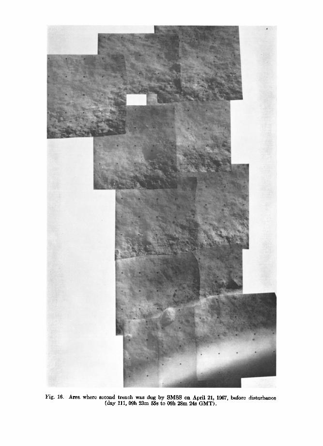
Fig. 16. Area where second trench was dug by SMSS on April 21, 1967, before disturbance (day 111, 09h 23m 55s to 09h 28m 24s GMT).

Fi•. 17.
•'•. :i.•:: .;i;•: '"
Second SMSS trench mosaic with SMSS in position after first pass through trench on April 22, 1967 (day 112, 11h 18m 00s t.o 11h 19m 33s GMT').
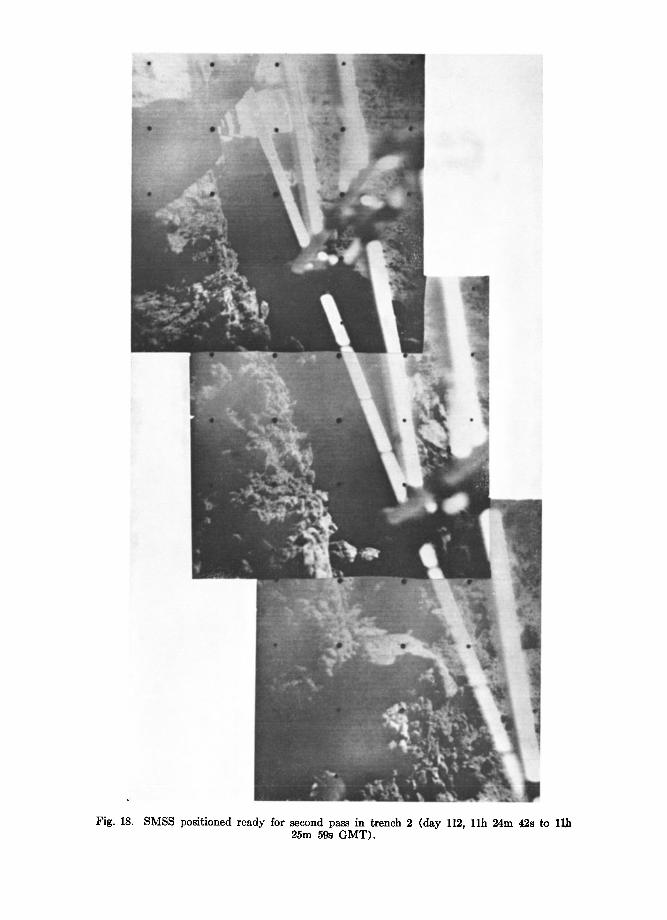
Fig. 18. SMSS positioned ready for second pass in trench 2 (day 112, 11h 24m 42s to 25m 59s GMT).
SURVEYOR 3--SOIL MECHANICS SURFACE SAMPLER 4065
%::p•i;::::/::;.-: ::• ...... •:/:S½:ii•::::ii½::• "-•,;-.4"- •'"':½ i'•;.::.,. :::.,-.-•--•
$•ai•ii,:, ................. ;!i :•;!i •;;;,$,,:, .•,. .•i. :.,..•0.• .....;::.:•i• -
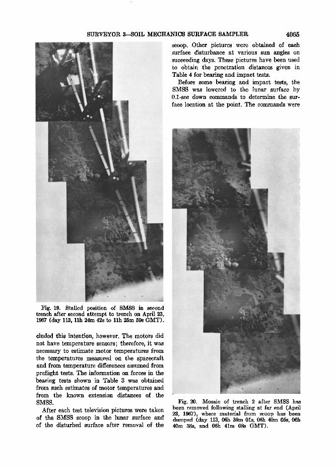
F•. 19. Stalled pos•don of SMSS •n second trench after second attempt to trench on April 23, 1967 (day 113, 11h 24m 42s to 11h 25m 59s GMT).
cluded this intention, however. The motors did not have temperature sensors; therefore, it was necessary to estimate motor temperatures from the temperatures measured on the spacecraft and from temperature differences assumed from prefiight tests. The information on forces in the bearing tests shown in Table 3 was obtained from such estimates of motor temperatures and from the known extension distances of the
SMSS.
After each test television pictures were taken of the SMSS scoop in the lunar surface and of the disturbed surface after removal of the
scoop. Other pictures were obtained of each surface disturbance at various sun angles on succeeding days. These pictures have been used to obtain the penetration distances given in Table 4 for bearing and impact tests.
Before some bearing and impact tests, the SMSS was lowered to the lunar surface by 0.1-sec down commands to determine the sur-
face location at the point. The commands were

4066
ß .• •..• .......... • .,.•.
ß ..•.. .•....••• ß
..
ß .;? •,•.•.,,.;%d ...• " '•-,•5•.../'•' .. ...... .• .•;•;ii!i• •" ....... • ;-':-•;• '....•' ....
drags through i• on April 24, 1967 (day 114, 05h 10m 33s to 06h 18m 51s GMT).
repeated until no further downward motion was detected. Although these operations im- posed loads of 10 • dynes on the surface, only a small amount of disturbance caused by the blade tip was observed.
T•'enching. Three trenches were dug in the lunar surface with the SMSS. The first trench
was excavated with only a single pass of the SMSS, whereas trenches 2 and 3 were sub- jected to repeated passes. A bearing test was made on the floor of trench 3. A fourth small
trench was made for the purpose of carrying
SCOTT AND ROBERSON
out an impact test at a depth of from 5 to 7.5 cm.
The first trenching pass of the SMSS pro- duced an excavation about 5 to 7.5 cm deep; the second pass deepened the trench to a depth of 10 to 12.5 cm (see Figure 25); a third pass produced a trench of from 15 to 17.5 cm deep. The motion increments produced by a 2-see retraction command of the SMSS vary with the load acting on the SMSS. When the force reaches a limit determined by temperature and spacecraft voltage, the retraction motor stalls and no retraction is obtained. It was found that
the first pass in a trenching operation pro- duced a trench of from 38 to 50 cm long with about twenty 2-see retraction commands. Motor stalling was observed in the second (see Figure 20) and third pass in each trench. As many as seventy-five commands were required to com- plete the third pass through trench 2. This behavior may be explained by the following two statements:
1. When a trenching operation is begun at the surface, the material is free to move side- ways out of the way of the advancing scoop. When the trench has been excavated to a depth of several centimeters, the soil scraped from the trench floor accumulates and cannot get out of the way of the advancing, fully packed scoop (Figure 25).
2. There is a possibility that the lunar ma- terial becomes stronger or denser with depth.
Two tests were designed specifically to clarify the second explanation. In the first test, a bearing test was performed on the material at the bottom of trench 3, at a depth of from 5 to 7.5 cm below the surface (bearing test 4). In the second test, two open-scoop impact tests were performed on the undisturbed lunar sur- face adjacent to a trench (impact tests 11 and 12), and an open-scoop impact from the same drop height above the impact surface was made in the bottom of the trench, at a depth of from 5 to 7.5 cm below the lunar surface (impact test 13).
It is not possible, at this time, to make cal- culations about the lunar material properties from the trenching operations. Further evalua- tions of the lunar data must be conducted in
combination with SMSS laboratory tests. The explanation for the small motion increments of
SURVEYOR 3--SOIL MECHANICS SURFACE SAMPLER 4067
the retraction motor observed under no load
must be understood before the retraction forces
can he estimated.
Impact. The bearing tests provide informa- tion on the static strength properties of the lunar soil. The tests primarily involve the soil's shearing strength, in which density plays a part. Impact tests were conducted to obtain further information on soil density in the absence of the motor current data, which would have enabled the weight of a scoopful of soil to be measured. In such tests, the penetration of the
SMSS into the lunar soil is resisted by both the static strength and the density of the soil. The contribution of the soil's density is greater as the impact velocity increases.
The SMSS is a flexible arm on which vibra-
tions are excited both by the release of the clutch, which initiates an impact test, and by the actual impact. Therefore, a complete anal- y. sis of the motion of the SMSS during impact is complicated. At this time, only approximate soil density comparisons can be made between terrestrial laboratory experiments and lunar
Fig. 22. General a.rea. survey of trench 2, improved mosaic.
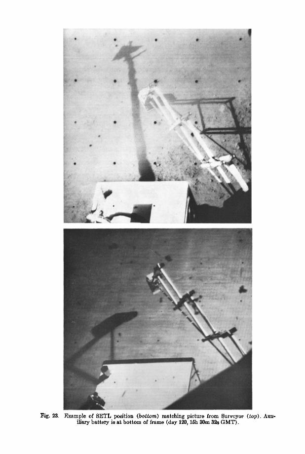
Fig. 23. Example of SETL position (bottom) matching picture from Surveyor (top). Aux- iliary battery is at bottom of frame (day 120, 15h 30m 32s GMT).

SURVEYOR 3--SOIL MECHANICS SURFACE SAMPLER 4069
impact tests. On the moon, fourteen impact tests, from a variety of drop heights, were con- ducted at different locations within the reach
of the SMSS on and below the lunar surface.
The results of those tests are presented in Table 3; their locations are shown in Figure 4. The drop height given in Table 3 is, at present, approximate. As an example, the result of im- pact test 3 is shown in Figure 26.
Material handling and dumping. Following a trenching operation, it was frequently found that some of the lunar soil remained stuck to
the inside of the SMSS, even when the soil was disturbed considerably. On occasion, this mate- rial fell out onto the undisturbed lunar surface, leaving patches or trails of excavated material, as seen in Figure 27.
In the process of excavating the second trench, a lump of lunar material was found below the scoop. The door was closed on the lump to find out if the material was solid or composed of an aggregate of finer particles. Because the scoop door closed with no observable difficulty, it was concluded that the lump was, in fact, an
aggregate. As a check, the portion of the lump that was pinched off and enclosed in the scoop was transported to footpad 2 and dumped on the footpad for televi.sion observation. The material disaggregated on dumping, as seen in Figures 7 and 8.
At another location (point H on Figure 4) an object (about I cm in diameter) with higher albedo than the lunar surface was picked up and transported to footpad 2. While the object was being dumped on the footpad, more soil fell out of the scoop and buried the object. The ob- ject was, however, later identified on the foot- pad. A third object, also of higher albedo and approximately 2.5 cm in diameter, was located embedded in the lunar soil adjacent to the head of the second trench. It was excavated and
picked up in the left side of the scoop, as shown in Figures 11 and 12. In clasping the object, the scoop door exerted a force of about 2.5 X 10⁶ dynes. The object was restrained by the edge of the scoop, which is 0.1 cm thick. If it is assumed that the bearing area on the object was 1.2 cm long and 0.1 cm wide, the scoop door exerted a
TABLE 3. Summary of SMSS Bearing and Impact Tests
Test GMT Force, Penetration, Drop Height,
dynes X 105 cm cm
Bearing 1 Bearing 2 Bearing 3 Bearing 4
Bearing 5 Bearing 6
Bearing 7 Bearing 8 Impact 1 Impact 2 Impact 3 Impact 4 Impact 5 Impact, 6 Impact, 7 Impact 8 Impact 9 Impact 10 Impact 11' Impact 12' Impact 13' Impact 14
Day 112, 05h 07m 01s 49 2.5 Day 117, 08h 45m 20s 27 2.5 Day 117, 09h 21m 55s 22 1.9 Day 118, 13h 32m 44s 27 0.6
Day 120, 15h 35m 31s 27 Day 120, 15h 45m 42s 4.5-9
Day 120, 15h 48m 50s Day 120, 15h 59m 18s Day 119, 09h 27m 02s Day 119, 09h 42m 02s Day 119, 09h 49m 04s Day 119, 10h 08m 29s Day 119, 10h 16m 45s Day 119, 10h 26m 40s Day 120, 16h 17m 06s Day 120, 16h 24m 57s Day 120, 16h 32m 45s Day 120, 16h 41m 30s Day 122, 12h 38m 33s Day 122, 13h 03m 40s Day 122, 13h 30m 37s Day 122, 14h 07m 29s
27
29
2.2
Compressed clod 2.9
1.9
1.3 3.3 2.5
3.8
4.3 3.8 1.3 1.6
1.6 1.6
6.3 6.3 1.3 5.1
(In trench bottom)
15
30 30 60
60 60
30 30 60 60 15
15
15
78
* Scoop open; for all other tests, scoop closed.

4070 SCOTT AND ROBERSON
...:..... ß ......:.... ..::...:..•...:,•:,.:. .... :...:.:..:.....::.-::......::; ...:•::;.-:...:•:.:........ +%. :....:...j....•,......::.................. ...... . ....... ...... .:........:..... .... ß
ß
"' .': .... .... -? .... :*" ::;'*':-., :' :,:.;'": .... 3" ...-:"': : ß {-: .. ... ß • - .. :, . .. ;. * . •:-.•:' .:;.• ;<•:::::,: '. ..... ..
$ .... :...,,a'**":'.*•.;:...½.•':?':-...:...::..:...... ..: 's,., '" ... '"•..; :"'* ..... . .... s.; :.} **•*:..: ".*'., .'.- .'. ...... . ?/:/:j?:; ...; ß
..::•;::•.::•:•":':**,/:..*•.:,;'":::.;:<':::**•*½,'*'•::5 -' ' - . - - •. *************************************************************************************************************************************************************************************************************************************************************************************************************************************************************************************************************************************************************************************************************************************************************************************************************************** •
.{
:.;2;...::;:?:,•,%.. w:;'• ......
..
..•;•: ....... ,•, ;; .............. •/•:. * .. :-.- ,., :,.•... ,.,
ß •.. :..,
.... ..
- .. :•;•:•:,..•:.,:.• ,: .--::*. .
Fig. 24. Picture showing SMS8 on April 22, 1967, (•) before (d,y 112, 05.h 07m 01s GMT) •nd (8) after completion of fir's• l•nar su•,ee bearing •est (05h 17m 27s GMT).
Test
Depth of Dimension, Penetration, Pressure,
em cm dynes/cm'-
Footpad SMSS closed
SMSS open
20 5 4 X 10 • 2.5 2.5 2 X 10 'i 0.32 3.8-5 1 X 10 •
stress of the order of 2 X 10 • dynes/cm •'. More of the lighter surface of the object was apparent after it was picked up than when it was em- bedded. The lower surface, as seen in Figure 12, is darker. The scratch in this lower surface was
probably made by the scoop in excavating the object and may indicate that the lower surface is covered with the darker soil.
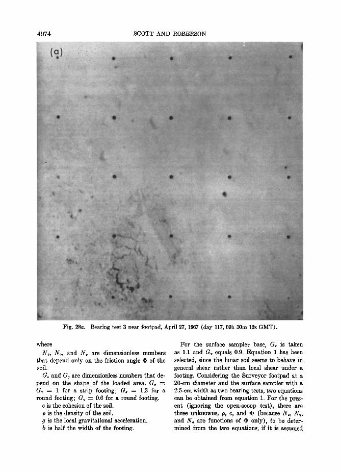
Homogentry o/ lunar soil. From the bearing test penetrations, it appears that, considering the probable variation in the force applied to the lunar surface, the lunar material is relatively
TABLE 4. Bearing Test Results
homogeneous over the test area of 1.9 m •' (see Figure 28).

SURVEYOR 3---SOIL MECHANICS SURFACE SAMPLER 4071
With reference to the impact test area, how- ever, it appears that somewhat less penetration occurred for impact tests 7 through 10 in the vicinity of the auxiliary battery than took place in impact tests i through 6 at similar drop heights in the area closer toward footpad 2 (see Figure 29). It should be noted that this varia- tion may be due to changes in the drop heights caused by SMSS elevation motor changes and a result of the spacecraft attitude, rather than to differing lunar surface properties. Also, impact test 4 may have been too close to a previous test. If, however, the differences result from the soil properties, two factors that can effect changes are the strength and the density of the material.
No substantial differences were observed in
the resistance of the soil encountered in the
different trenching operations. Depth variation o• lunar soil properties. In
the bearing tests, the SMSS was lowered by one
2-see command into the lunar soil. Then, the SMSS was given successive 2-see commands, which resulted in small additional penetrations. When the movement ceased, the bearing test was terminated. In the absence of motor current
measurements, a detailed evaluation of the rela- tion between force and depth is not possible. Characteristically, a penetration of 1.9 to 2.5 cm was achieved in a bearing test at the lunar surface. However, bearing test 4, conducted at the bottom of the third trench at a depth of approximately 5 to 7.5 cm below the lunar sur- face and probably in disturbed soil, gave a penetration of about 0.6 cm, as shown in Figure 30. This fact, together with the difficulties observed in making the second and third passes through a trench (even considering the effect of trench confinement mentioned), appears to in- dicate that the lunar soil is firmer or denser
below this depth. The comparison of the open- scoop impact tests 11 and 12 on the undisturbed
Fig. 25. Second pass of sampler in trench 2 (April 23, 1967). Note material ahead of scoop as it is drawn toward spacecraft (bottom of picture) (day 113, 07h 22m 04s GMT).

4072 SCOTT AND ROBERSON
Fig. 26. SMSS scoop is shown embedded in the lunar soil following a drop from a height of about 30.5 cm in impact test 3 (April 29, 1967). A previous. SMSS impact, impression is shown in top left corner of picture (day 119, 09h 49m 45s GMT).
surface with impact test 13, conducted on the material at a depth of 5 to 7.5 cm below the surface, confirms that the material is, indeed, stronger or denser below a depth of from 5 to 7.5 cm.
When the scoop was rested on the lunar sur- face under a vertical force of an estimated
4.5 X 10⁵ to 9 X 10⁵ dynes, little penetration was observed. Therefore, it appears that an extremely soft upper layer does not exist in the immediate vicinity of Surveyor 3. Under the high sun at lunar noon, the detailed texture of the rough surface is no longer visible, and a clear picture of the distance to which the soil is disturbed by a bearing test can be obtained, as seen in Figure 31. The cracks in the ground surface are the surface manifestations of the
underground displacement caused by the test. The cracks are not the result of the presence of a surface crust of stronger or more brittle mate- rial.
The higher albedo of the undisturbed lunar surface compared with the albedo of the dis- turbed material in trenches appears to be an extremely shallow effect, as seen in Figures 10a and 10b.
As far as can be determined from the SMSS
operations, any change in the soil grain size with depth takes place below the resolution of the camera. There i.s no obvious albedo change with depth once the lighter surface material has been disturbed. The albedo of the smoothed
surface ca,sed by bearing test 4 on the undis- turbed surface in a trench floor will be studied.
ANALYSIS
This part of this paper discusses the analyses of the SMSS operations performed to date for the purpose of determining the lunar soil prop- erties. The tests referred to are the bearing tests, because the uncertainty over the retrac- tion motor torque leaves the trenching forces

SURVEYOR 3--SOIL MECHANICS SURFACE SAMPLER 4073
still unccrta, in a,t this time. Analysis of the impact tests is still incomplete.
Bearing tests. Three bearing tests using dif- ferent sizes of footing have, in effect, been con- ducted: the Surveyor footpads with a diameter of 20 to 30 cm, the SMSS with the scoop closed, and the SMSS with the scoop open. The results of these tests are given in Table 4.
It is considered that fa,ilure or yielding of the soil by general shear [Scott, 1963j occurred in all these tests. Therefore, the pressure rep- resents the static bearing capa, city of the soil at the depth of penetration achieved. The value
used for the bearing capacity for the footpad is deduced from the Surveyor I landing It is com- patible with the data obtained from the Sur- veyor 3 landing. The expression for genera,1 shear was selected because the soil behavior in
a static bearing test appears to be relatively incompressible.
The bearing capacity, p, of a, footing at a shallow depth, z, below the surface of soil is [Scott, 1963] given approximately by the ex- pression
p - GcNcc • G•N•pgb • N•pgz (1)
;Fig. 27. SMSS in position to begin picking up object. In moving SMSS to this position, materia! from a trenching operation has fallen from sco,op leaving a dark trail across the lunar surface (April 28, 1,967). ;Bearing tests 2 and 3 are seen to the right of the SMSS; trench 3 is obscured by the SMSS (day 118, 09h 48m 08s GMT).
4074 SCOTT AND ROBERSON
':•:• ................ •2• ....................... ........... • .... "' • v...• .• •..• •'•'•••••••••••-• • •""•••w•'•--•••.'-.•'--:•_• -'-'mm• ................. :?w•-•'.'.•::•"-•
Fig. 28a.
...
Bearing test 3 near footpad, April 27, 1967 (day 117, 09h 30m 12s GMT).
where
N,, N,, and N• are dimensionless numbers that depend only on the friction angle ,I, of the soil.
G, and G, are dimensionless numbers that de- pend on the shape of the loaded area. G, = G• -- 1 for a strip footing; G• ---- 1.3 for a round footing; G, -- 0.6 for a round footing.
c is the cohesion of the soil.
p is the density of the soil. g is the local gravitational acceleration. b is half the width of the footing.
For the surface sampler base, G, is taken as 1.1 and G, equals 0.9. Equation 1 has been selected, since the lunar soil seems to behave in general shear rather than local shear under a footing. Considering the Surveyor footpad at a 20-cm diameter and the surface sampler with a 2.5-cm width as two bearing tests, two equations can be obtained from equation 1. For the pres- ent (ignoring the open-scoop test), there are three unknowns, p, c, and ß (because N,, N,, and N• are functions of ß only), to be deter- mined from the two equations, if it is assumed

SURVEYOR 3--SOIL MECHANICS SURFACE SAMPLER 4075
for the present that the lunar soil is homo- geneous to a depth of several centimeters.
There are many ways of determining the soil parameters The method selected here is to choose values of p compatible with the observa- tion that the material is granular, is relatively incompressible, and has a deformational be- havior qualitatively similar to that of terrestrial soils. For each density, values of cohesion c and internal friction • of the lunar soil may be calculated. The values obtained are discussed in
terms of the observed behavior.
For the calculations, densities of 1.0, 1.5, and 2.0 g/cm 8 have been selected. For a solid min- eral component density of 3 g/cm 8, the porosi- ties shown have been calculated. The results are
given in Table 5. To show the variation that can be expected in the results, the values of cohe- sion and friction angle (values in parentheses) were calculated for a Surveyor footpad-bearing capacity of 2.8 X 10⁵ dynes/cm •. This value may represent a lower limit of the bearing ca- pacity at the footpad scale.
For a soil composed of solid mineral particles
Fig. 28b. Bea.ring tes• 5 nea.r a.uxiliary battery, April 30, 19,67 (da.y 120, 15h 40m 08s GMT). There is a.n obvious similarity in the imprints oœ these two tests, which are sepa.r•ted by • distance of several meters. Note sm•ll object below imprint in picture.

4076 SCOTT AND ROBERSON
F•g. 29a. Impact 4 from a height of about 60.9 cm near foolpad 2, April 29, 196.7 (day 119, 10h 0.8m 29s GMT).
of ordinary terrestrial density (about 3 g/cm'), a density of 1.0 g/cm 3 represents a material with a large proportion of void spaces, or high porosity. Such a soil does not exhibit the gen- erally incompressible behavior shown by the lunar soil in the bearing tests. In addition, the friction angle of a particular soil increases as the density increases and is in the range of 25 ø to 45 ø for soils with low to high densities. It is seen from Table 5 that the lower the den-
sity of the material is assumed to be, the higher must be the friction angle in order to explain the observations.
If the lunar soil were composed of porous mineral particles that did not break up during the bearing tests, the incompressible behavior could occur and the material could have a fric-
tion angle of 40 ø and at the same time possess a low density. A large proportion of the lunar surface material is, however, apparently com- posed of particles smaller than from 40 to 50 ttm in diameter. These small particles would
have to be porous for a lunar soil of low density to exhibit the observed mechanical behavior.
Although this possibility is not excluded, it seems more reasonable to conclude from the
calculations (see the tabulation) that the lunar surface material has a density in the range of 1.5 g/cm 3 with an accompanying cohesion of about 1.4 X 10³ dynes/cm • and a friction angle of about 39 ø .
In bearing tests of this type, the soil is typi- cally uplifted and disturbed on the surface to a distance that depends on the angle of internal friction of the material. For the 2.5-cm width
of the SMSS base, a material with an angle of friction of 30 ø would be disturbed to a distance
of about 7.5 cm from the edge of the base, and a material with an angle of friction of 40 ø, to a distance of about 17.5 cm. It is observed in the
SMSS bearing tests under a high sun angle (Figure 31) that soil disturbance takes place to a distance of at least 10 to 12.5 cm, indicating an angle of internal friction of at least 35 ø . The

SURVEYOR 3--SOIL MECHANICS SURFACE SAMPLER 4077
nature of the displacement phenomenon ob- served in the bearing tests indicates that the soft density does not change appreciably during the test.
For any of the discussed soils, a calculation using equation i applied to the open-scoop SMSS bearing test indicates that a much greater depth of penetration should have been obtained under the vertical force employed. The indica- tion is, therefore, that below a depth of about 5 cm the lunar soil is substantially firmer or denser, which confirms the soil behavior ob- served in the trenching tests.
This increase in strength affects the calcula- tions of the soil properties based on the bearing tests, because the size and depth of penetration of the spacecraft footpads are such that the assumption of vertical homogeneity cannot be made. In this case, equation I cannot be used and the relative values in the tabulation are
not correct, because the firmer soil (assuming it existed also at the Surveyor 1 site) would affeot the penetration of the spacecraft footpad. In a homogeneous material of the same average char- acteristics as the top 5 cm of the lunar soil, the spacecraft footpad would have penetrated deeper at the same applied pressure. If this considera- tion is used to reevaluate the data, it appears that (for all the assumed densities) friction angles would be from 2 ø to 3 ø lower and the cohesion would be perhaps 7 X 10 2 dynes/cm 2 higher. The small amount of cohesion appar- ently present in the lunar soil leads to the tenta- tive conclusion that Van der Waals forces, rather than primary bonding forces, are causing the cohesion.
It is possible that the increase of strength with depth is a phenomenon associated with the Surveyor 3 landing position, because legs 2 and 3 of the spacecraft apparently rest on or near
Fig. 29b. Impact !0 from a height of about 60.9 cm near auxiliary battery, April 30, 1967 (day 120, 16h 41m 30s GMT). There is a difference in the depths of penetration. in these two tests.

4078 SCOTT AND ROBERSON
:• .• • "t;-•. •'• ...
• .......
•,;•.. •?• ..-•:•-:.. •...•:•: ß
•;•. -•,-•-•, '-'---'."-:':• •'•
.... • '• ..• :7• ......................... .:
ß :... •"•(•.•.:• .•.>. :• •,. *;•-•.• •?•.•...'•'r•': ........ :•-'-'..• •.:
..:' ........ •:.:... ::.• ..:•"•' :..:;h: '•' , . :• .... -.'•.: ß :.. •:. .....,..
:.:. ß . • ..... ....- .-•.•
•: :5 ...... '" "?"?'"• -' . ........
Fig. 80. Bearing tes[ 4 impression in bottom of trench 8 a[ a depth of 5.1 to 7.6 em below lunar surface (April 28, 1967). Dep[h of impre,ion estimated from shadow. 8oil broken up by [renehing operation is visible (day 118, 18h 8•m 22s GMT).
the rim of a small shallow crater and the SMSS
tests were performed on the rim material. If this is not the case and if the increase in
strength with depth is a general lunar feature, there is no obvious reason why there should be a sudden increase at the 5-cm depth. It is possible, therefore, that there is a gradual in- crease with depth. The lack of SMSS motor current data precludes any confirmation of this property assumption.
Because trenching was performed to depths greater than 5 cm, further analysis of the trenching information may yield quantitative results on the soil profile below that depth.
Trenching. The reactions of the retraction motor are still being analyzed to determine the reasons for the anomalous behavior. The forces
applied by the SMSS to the lunar soil during trenching operations remain unknown.
In an attempt to measure these forces, trench

SURVEYOR 3--SOIL MECHANICS SURFACE SAMPLER 4079
4 was dug on day 122, after turning on the strain gages on Surveyors' shock absorbers. A preliminary analysis of the static strain gage readings immediately following the landing indi- cates that a change in the force in a shock ab- sorber of amount greater than 4.5 x 10⁶ dynes could be discriminated in the strain gage record. The strain gage traces obtained during the trenching test show no indication of any load level change. It is, therefore, tentatively con- cluded from further analysis that the SMSS was
exerting a retraction force of less than 4.5 X 10⁶ dynes on the lunar surface during the formation of trench 4. Still further reduction of the strain
gage records is planned. Impact tests. A complete analysis of the im-
pact tests cannot be given at this time. How- ever, the velocity of the surface sampler at con- tact with the lunar surface from a drop height of 60 cm (corresponding approximately to four 2-sec elevation steps) can be estimated to be about 2.1 to 2.5 m/sec. Laboratory tests have
Fig. 31. Imprint of bearing test 2 observed at high sun (April 27, 1967). The. cracks c•used by the test and extending to the surface of the soil are clearly seen (d•y 117, 08h 56m 45s GMT).

4080 SCOTT AND ROBERSON
TABLE 5. Soil Property Calculations
Angie of Density, Cohesion, Friction,
g/cm• Porosity dynes/cm8 deg
1.0 0.67 9 )4 102 (5.5 X 10⁸) 42 (33) 1.5 0.50 1.4 X 10⁸ (8 X 10⁸ ) 39 (30) 2.0 0.33 i 7 X10⁸ (1 XlO 4) 37 (27)
been performed on earth with a prototype SMSS striking various soils at a range of veloci- ties. For a slightly higher impact velocity than the value given for the SMSS moon impacts, laboratory tests on densely packed dry sand (density about 1.7 to 1.8 g/cm'), with the scoop closed, have given penetration depths of 1.6 to 1.9 cm. Such a soil has a friction angle of about 40 ø and is essentially cohesionless. Comparison of the SMSS lunar impact tests with the ter- restrial tests indicates that the material densi-
ties are comparable, although preliminary anal- yses indicate that penetration depths at these impact velocities are not very sensitive to den- sity. The density of the terrestrial tests (about 1.5 g/cm •) would be compatible with the value in the analysis of the static lunar results. The effect of the stronger or denser lunar soil layer below a depth of from 5 to 7.5 cm on the impact test results remains to be investigated. It would tend to lessen the penetrations.
Material handling. Because the disturbed lunar soil remains in the open SMSS scoop above the lunar surface, it can be calculated that it possesses a cohesion greater than about 3 X l02 dynes/cm •' for an assumed density of about 1.5 g/cm 3. Since the walls of the trenches have not collapsed at a depth of 15 to 17.5 cm,
it appears that the cohesion may be at least 10 • dynes/cm 2. In one impact test conducted with the scoop open, a quantity of soil was dumped on the lunar surface almost equal in volume to the capacity of the scoop, as near as can be estimated. In such an impact test, the maximum deceleration is in the range of from 5 to 10 earth g. Therefore, the upper limit of the cohesion of the disturbed soil to the scoop can be estimated as being about 10' dynes/cm 2.
In one bearing test, an object (see Figure 2Sb) resting on the lunar surface was depressed and found to crumble under a relatively gentle pressure (contact 3, item T in Figure 4). It is concluded that this object was an aggregate of smaller particles, as was the clod of material broken by the scoop door at the foot of trench 2. One of the objects of higher albedo that was picked up seemed to have a substantially greater strength than these clods, and it may be termed a rock.
Ackno.wledgments. We express special appre- ciation to M. C. Claw of JPL for his analysis of the performance of the mechanism and auxil- iary during the mission.
The work described herein is performed by the senior author under contract JPL-CIT 69811 with the Jet Propulsion Laboratory. The surface sam- pler was designed and constructed by Hughes Aircraft Company, E1 Segundo, California.
l•EFERENCES
Scott, R. F., Principles o/Soil Mechanics, Addison Wesley, Reading, Mass., 1963.
Scott, R. F., Soil mechanics surface sampler ex- periment for Surveyor, J. Geophys. Res., 72(2), 827, 1967.
(Received January 23, 1968.)