soil data cover sheet geotechnical - swppp street montessori soil data.pdfir kc investigation has...
TRANSCRIPT

SOIL DATA:
Riddle Street Montessori
in
McKinney, TX
This information was taken from the Geotechnical Data report done by Pogue Engineering & Development Company, Inc.
PROJECT NO. f 5598 JULY, 20@8
CEOTECWNICAL fNVESTIGA7103' PROPOSED BUXLDlNG
HUDSON CROSSIWG hqCKIX5EY. TEXAS
Presenrcd To: POGUE ENGfItr"EER1NG &
DEVELOP3IEFJT COMP:IhT, ISC. 3ICKINWEY, TEXAS
#

July I U. 2E)Og Project No. 155913
3%. Sandra Green 45 Bogue Engineering L)e.i.elopmenr Company, Inc." 15 15 Heritage Dnt e . Suire 105 I\?icliinrtcj, 'ksas 75069
GEOTECHNICAL IEVES'FIGATION PROPOSED BtiIlLDfSG
HUDSON CROSSING hlCMN?J%Y, TE,X4S
Dear Ms. Green:
"l'ransmitted herewith art: copies of the referenced report. Shoufd you have any questions concerning our findings or if you desire additional inromation, do nor hesitate ts call.
; ,F. J f--
'
- P z L
i
i: i <,
' ,- ir i Q [
copies submitted: r 3, -, - i: C
I' L
, - i ,. L .- < - 1 1 .
'i'
* k , ' " - $
/ '
r m - - z - .,rue - ~ - t v < . = A , E h G l N E E R l N G
i V ~ ~ : , $ t S t ~ t . f % T i t CONSULTING
=::.~TRJcT;ON 5A:ES.L'LS TESTING

'TABLE OF COSTENTS
* PAGE
Project Descripfion ................................................................................... 1 ......................................................... ...................................... Authorization ; 1
Purpose and Scope ............................ .., ................................................... 1
7 FlELD AND LABORATORY INVESTIGAT10NS ........................................... - Generat ........................................................................................................ 2
....................................................................................... Field Investigation 2 Laboratory Testing ...................................................................................... 3
(~ENER4L SITE CONDITIONS .......................... ... .............................................. 4
Physiography ...........................................#.....................*..+......- -. 3 .............. ...................................................................................................... Geology 4
Stratigraphy .................... ,. .......................................................................... Croult.ld Water ........................................................................................... 6 Texas Health and Safety Code and TCEQ Comment.. ............................ 6 Seismic Site Classif-teadons ....................... .. .... 6
.......................................................... ANAL YSIS AKD RECOMMENDATIONS 7'
Potential Vtrtical Movements ................................................................ 7 ................................................................................... Foundation - General 8
Founda!ion Design - Picr and Beam Foundation ................................ 8 Grade Beams - Pier and Beam Foundation ......... ... .................................. 11 Flear Slab - Pier and Beam Foundation .................................................... I 2
......................................... Foundation Design, Milsnotithic 'Wafflev Slab I 6 .................................................................................................... Earthwark 19
....................................................................................................... Pavement 20 3 7 Pavement Joints ................ ..,, ....................................................................... -- 1 - Construction Observation and Testing Frequency ................................ ~3

TABLE OF COETENTS (Continued) *
PLATE
P14.4iv OF BORINGS ................................................................................................ I
7-4 ............................................................................. BORING LOGS ........................ : - KEYS 10 TERMS ASD SV3-ZBQLS USED ......................................................... S&6
LABOLITQRY TEST RESULTS ........................................................................ f
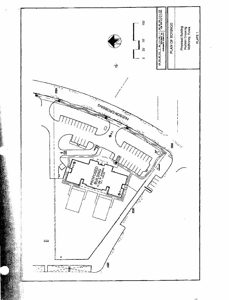
1"roject Description This report presents the resu4ts of a geotcchnical investigation performed for a proposed
building ro be located nonhwcst sf the intersec*a of Hudson Crossing and S t , James Place in
MuKinrar?;. t'esas. Ihe project consists of a 1 0,385-square foot, single-stary dzty care building
imcl associated parking and drives. Finished floor is planned at Elcv. 7 48.55,
']̂ he general orientation of rhe building is shs.iin on the Plan of Borings, Plate 1 of the report
Illustrations.
:Xuthorizafion Tlis invesfigatiedn \vas aurhorized by Ms. Bhoorna Srinivasan, u w e r of Riddle Street
ktonkessori School by signature of irur Proposal No, 5-77 an June 13, 2808. Ihe s i s d
proposal uYas received by this office on June 18,2008,
Purpose af~d Scope ?he purpose of this incestiga~ion has been to cmtuste the general subsurface condilions and
provide r~commendations br:
desisn of the fouadation system;
floor slab;
pavement subgrade: and
* site preparation and earth~ork campaction criteria.
Projec~ So. is598

. " Ir kc investigation has included drilling sample brings, performing laboratory testing, andping
engineering and geotclgic data md developing geotccknical recommendations. The following
wclions present :he rttcthodologj uscd in this investigation.
Rec~mmcndations pmrided hcrein arc%ite-spefific and were drvclopcd for the project
discussed IR the repn Introduction. Persons using this report for other than the intended
purpose do so at their awn risk.
General The field and lahom~ary in\-estigations h ~ v c been conducted in accordance svith applicable
srandnrcfs md procedures set hrth in the 2008 Annual Book of ASTM Standards. Volumes
&!.US artd 04.09, "Soil and Rock." 'Thesc valumes should be consulted for irnfnrmatjon on 1
Field Investigatian Subsurface conditions were evaluated by 3 sample brings drilled to depths oFS-1!2 to 19 feef
in June 2008. The locations of che brings are shotm on Plate I of the report lilustratians.
i3onngs \\ere advanccd bet\%ren sampling intervals by means of a tnrck-msuntcd drilling rig
cc jn tp~d with continuous flight augers. Samples of tohcsive soils were obtained with 3-inch
diameter Staelbj tubes (ASTM .I-1587). Mfeathcred and untveathcred linaestone \vat; evaluated
in-situ using the Texas Depanment of"f rmsprtatiora (TxDO'r) cone penetrometer Icst.
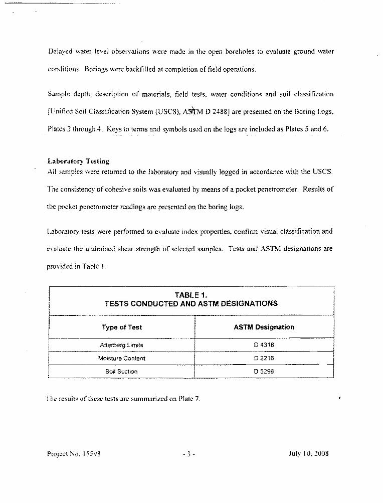
Delti>eJ water fete1 observations were made in thc open bareholes :o exialuate ground ~vater
corrditiottr;. Bori~~gs nerc kickfilled at cornpiction of field operations.
Samplc depth. description of materiats, fieid tests. water conditions and soil classificariuri
(I'nitied Sail Classifkarion System (USCS), ~ ~ $ 3 . 1 D 24881 are presenled on the Boring l.ogs,
Platcs 7 through 4. Keys to terns and symbois used on the togs are incfuded as Platcs 5 and 6 .
Laboratoq Testing All s;trnglcs itJerc: returned (LO rEe faborator): and v~sually logged in accordance with the LJSCS.
l'he consisttncy of colaesiit soils ~ r a s evaluated by means of a pocket pcnetromctrr. Results of'
rhe pocket penetrometer readings we presented an the boring logs.
1-ahorat on LesQ ivcrc perfomeel to ei7alu;lle index properties? canfirm visual elassif? cation and
ekaluate the undrained shear strength of selected samples, Tests and iZSTM designations %.re
prskidtd in Tabfe 1 .
TABLE 1. TESTS CONDUCTED AND ASTM DESlGNATIONS
July 10, 7008

Ph? siogcaph y
Based en obscn-ations of the sitc Juriylg the field investigation, and on aerial photographs
tlbtalncd &am the Yorth Central Texas CouyciI of Governments VU'TCOG), ahc sitc \'as -& 7-
cut ered with shon igisses, :I soil mound iv~i5 present in the north-central portion of the sitc. A
transtidrmcr pad and a small unidentified structure were present in the southeast portion of the
Based O:I a site grading plan received from Pogue Engineering and Development Company, Inc.
on June 8- 2008. the site sIopes generally to the west. Site grade varies from Elev. 537 in the
\iesaern portion of the site to Elev. 751 in the northeast portion. Topgraphic relief across the
site is esrirnated to be on the order of 13 feet.
Cecslqy !he site oxitrlics the. I.;pper Cretacealts Austin Chalk Formation, In its unwrcatilerecl stare. the
:lustin Chalk consists of gray, hard. chalky limesronc interbedded with thinner beds of
calcareous shale. ldpon \veathcn'ng, the :\erstin Chalk becomes tan moderately hard and joinled
iiith rhinner inrerkdr of edca~eous cia?. Complete wearhering produces deposits of
modcralcly to bight? plastic residual clay.
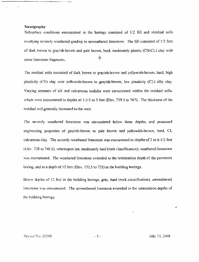
Stratigraphy Subsurface conditions encounttlred in the borings cunsis$;tcd of I12 fill and residual soits
overlying sc\,erely \iealhcrcJ grading to unweathered Iimcstone. The f i l l consisred of 1'2 fool
of dark b r o w ro grayish-brown and pale brc3w-11, hard moderately plastic (CW-CL) clay tsirh
sexme Iin~cstone fragments. Y& *"
-1be residual mils consisted of dark brown to grayish-brown and yellowish-brown, hard, high
plasficiry (CIif clay over yellowish-bmwn t o grayish-brown, few plasticity (61.1 silly day.
V a ~ i n g amounts of silt and calcareous nodufss were encountered within the residual soils.
whicir \sere encountered to depths of 1 -1.Q to 5 feet [Elev, 739.5 to 747). The thickness of'the
residual soil generally increased to the west.
I'he se\erety heathered lirnesrone was encowtered befnw these depths. and possessed
engineering properties of grayish-brown to pale brotvn and yeHowish-brown, hard, CL
calcarccsus cla). The severely wearhered limesforme was encountered to depths of-2 to 6-I!? feet
kl:fe\. 738 to 746.5). ~ \ h e r e a p ~ n tan, moderately hard (rock classification), weathered limestone
uas encounrered. The wcalhcred limestone extended to the termination depth c?f the pavement
boring, and to a depth of I2 feet QEier. 732.5 to 735) in the building brings,
Belo\\ depths of 12 feet in the building boring. gray, hard (rock classification). unweathered
:rmrnonc was encountered. The unweathered limestone extended to the termination depths of
rhz building borings.
July Iif. ?(I08

"EF*%B& tfl Bat P r -. - - - - %arc: was not ermc~un~ered during the field inucstigtiiion. Durins wetcr seasons.
- 3 - 4 + * sr -,z " -- -$A.L ' , , I + he ;wirfic$ above the reistit-ely impermeable, unweathered lirncstonc in upen
-- * - 2 ~ 3 3 :rscrures ~virhin the weathered limestone and in the over1ying residual soils. The
.--- - ** d . fek..l i d 3cptlh) of ground water wifi vary wrth sehtsonal and yearly rainfall.
TCIEZ~ HmtIPB and Safety Code and TCEQ Comment A "ve;xd.t Irr the 'I"r.xas Wealalth and Safety Code. Chapter 361, $361.538 and 30 'J'exas
3 ., -- ..,,.- q'Qh3v-v = .; c % Code 330, $330,953. Reed Engineering Group, Ltd. has: performed appropriate --+.. t:at\ as required by ~hcse rcpuiarions to demonstrate that the subject properly dues not
>.-zrE:z IP closed municipal solid waste 1-dfil i . The site obsewatlans and subsurface data do
- - ? ..a>& lndicare the presence s f buried municipal solid waste at this site. Bascd on these data,
le\ekpment of this site should nut require a Development Permit, as descr~bcxl in $361.532
.ad <$,130.95 1-330.963. Subchapter 1-
Seismic Site Classifisation Ihc site has k e n classified ~ i t h respect bf, seismic design criteria contained in the 2003
!nrcrnntiunal Building Code (IBC), Section 1615.1.5. l&e criteria require charactcrimion of
the Impper 100 feet of subsurt'ace materials. Based on thc fBC criteria, the site is classified as
Site Class 13 in accordance with 'Table 1615.1 . I .
t'rtsicc~ So. 15595

.ANALYSIS AXD WECOMMENDATIOSS
Potential Vertical illo~ements P ~ t i e n ~ i d l Vertical blovernents (PVM) \vex evaluated using an empirical procedure dcvclopcd
b: 3lcf>o~cI1' and l~lodificd by the Texas Department of Transportation, 3'xDO'T Test htrthod :&?
1 ~ - ! : ' in cc\r.rdtit~ction \\ith the soil suction tests. Based on existing grade. PV%l caiculatians
and 7351 crpcrience, potential rnovemenrs are enirnatd to be sn the ordcr of 1-112 inches.
?\,lot erncnt will he associated with seasonal changes In s ~ i t moisture,
Cwund-supported impravemerits (i,e,, sidewalks and paving) \Gfl move in response to changes
-. i n ?oil meist~re. I he rnoiement will be ohsewed as heave if the sails arc dry at the time rks
p:?!cmcnK t'rr sidenalk is esnstmctd. 'The movement ill be observed as scttlerncnt if the soiis
3ti' m~)ict ar thr. ~ i m c of ccmstructian. Generally, settlement will bc limited to the outer
perimeter jamer four to five feel1 of larger slabs. Prudent {satering during extended dry
climaeic periods can control senlernent. Recommendations are provided to limit movement
hclow the building; however. some movement of site paving and sidewalks should be
6
Xlei)ow~II , C: "The Relation sf L.abosaaoty Icsting to Llesigii ifor Pavements and Structures on Expansive Soils." Quanerl) ol'tbe CalordJo School of Mines. Volume 54, No. 4, 12?-153. - "'4r.thnd far t)eterrn~n!l?g !he Potrntiai Ve7tital Rise, PVR." ( I 975). Texas Depanment of rransprtat~on, Pest \,lclhod Vex-133-E.
Foundtttioln - General -I hc use of either a pier and beam Foundation with a ground-supported floor slab. or a post-
tensioned nr con\.cntionaitIy-reinforced slab-on-grade foundation is considered feasible.
Kceornmcndations ?or both i'ounda~ion types are provided in the follo~ving sections. Remedial
eanhirtlrlr is recommended uilh cithcr altema&e.
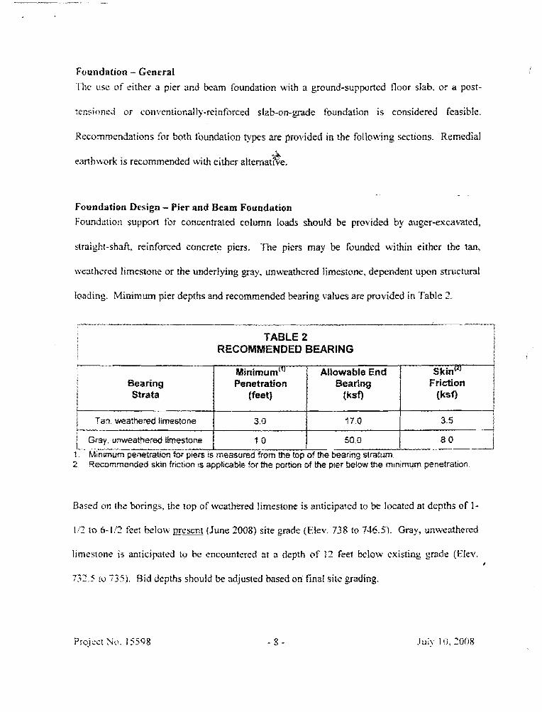
Foundation Design - Pies and Beam Foundation Foundation suppon for concen~ated eoiumn loads should be provided by auger-exca'c'ated.
straight-shaft, reinforced concrete piers. The piers may bt: founded within either the tan,
ueathcrcd limestone or the uaderfjing gay. unweathered Iimcseone, dependent upon srructural
loading. Minimum pier depths and recommended beating values are provided in 'lhkle 2.
"-*- " ---.,- -- t
i TABLE 2 I RECOMMENDED BEARING !
I
" -.......-"-p-*. f Rnrnrmum pnetrat#an for pters ts measured from the top of the bearing stratum 2 Recommended skrn fnctmn IS applrcabb for the porB8on of the p e r below t h e rnlnlmurn penetratrora
Based un the borings, the top of tveatfrered limestone is anticipated to be located at dcplhs sf 1-
1 '1 to 6-1!2 fect helo~t; present (funs 3008) site grade ( E k . 738 to 746.5). Grdy, un\vcathercd
limrst~ne is anricipa~ttd to bo encountered a? a depth af 12 feet below existing grade [Elev. I
732 5 !cr 7351. Bid depths should be adjusted based on final si~c grading,
3.12 TSWS of bearing marerials nlay be specified. Generaliy. this can be identified by a note on
---. ~fmbns such as '*.i fcctt into tan limestone, or y feet into gray limestone, uhichever ~ccurs
C - G ~ - f h ~ s wre uould allow on-sire construction ptrsomel the ability 10 limit pier depths
-kf-c~r' \he top of gray limestone is located at eater depths, and an adequate thickness of tan F ..::t'.!c~ife is presertt.
I he md bcaring and skin fricrion values are appIicable for portions of the piers extended below
mmifiinlurn penetration recommended liir each stratum. No partion of the pier surface zrea
;rba:a c ihc minimum penerration should be counfed on to provide shear (skin friction) resistance.
P~ers pnymtaiebned in accardance with these allowable bearing and skin friction values will have
a nlirlimum iiictor of safet) of three considering a shear or plunging failure. The wight of the
pie; ctrncrerc below final grade may be neglected in detemining fcrundatian loads. PmperIy
conu:rucld stmight-shaft piers should not tmdersa gas-cunstmc~ion elastic st7rttment in
euress of 1 '4 inch. For reasons of constructibifity, a minimum pier shaft diameter or 15 inches
i s recommended.
I>icrs will be subjcc~rd lo uplif't rtssociated with skvelling within ahe upper clays. f i e pier;
should contain reidarcing saw1 th~uughout rhe pier lo resist tkr tcnsife uplif forces.
Rcinfbrcing requirements ma) be estimated baed on an upfifi pressure of 1 .O kip per square
loot (ksf3 acting o\er the lop six feet of pier surface area. The calcuIated uplift value is
ctdnsidercd a working load. rlpprspri~e factors o f safety shouId bc applied in calculating the I
13rc>jcct So. 155% July 10. 2005
"\Iashroi~rning" or wiberairag of rhe upper portion of the pier shaft tvill sigificantly increase the
uplifi pressusc Tram the u p p a clays. "hfushrooms" should be renlo\*ed from thc piers p ior ta
back !i I l operations.
PIC: caps underlain by clay should nor bc I& with the piers unless a minimum void nT 3
:nchcs {fdcter of safety of 1.54) is created below the portion of the cap extending beyond the
shati diameter, Pier caps founded on or within the tan, weathered limestone will nut require
cansmlction of void bcneatb hem.
I'plift will be resisted by negative skin friction in the limcstonc. 1JpIift resistance can be
ca!culatcd using 2.5 hsi' within the tan, weathered limestone and 6.8 ksf k~ithin the gray,
unx\calhered Iirncsronc. Tf~e portion of the pier shafts above a minimum pcnetratiari into the
bearing stratum sltauld be neglected. The values above contain a minimum factor of safety of I
approximately t\\o. Dcvelopmont of the calcula~d resistance should require negligible
tnu\ erncnt o f the bsrtom cafthc piezr.
Grcund tvatcr \vas not encountered during he field investiga(ion. Close coordination cif'drilling
and eoncrcle placement should limit the necessity for casing or dc:'cVii1rring of pier excavations
tbr the majority time i ~ f the year.
Pier cvcavarlons should bc dry and free of deleterious mafe:riaIs prior to c-orrcrete placement. In
IPQ CilSC should the pier shsA exca~arions remain opcn for nrore than eight hnurs prior rn
cmcrete pfaccmrnr.

Cat?tirnuous obsenation o f the pier constmction by a represenfarive of this office is
rccornmended. Obscmarion is recommended to confirm the bearing stratum and vcri@ that the
txcava~ions are dry prier t~ placement of concrete.
*& Grade Beams -Pier and Seam Foundation Cirade kms underlain by clax should be constnrc:ed with a minimum void of 3 inches (factor
of safe'rry at' 1.54) beneath them. A void is recommendd to Eirnit potential foundation
nko\emcnts associated with ss\eliing af the underlying soils. Grade beans founded directly on
or: xvithir: competent wearhered limestone \+-ill not require eonsmctisn of a void.
'Ihe efsid can be. ctearcd by use of wax-impregnated cardboard forms, Keainer b o d s along
the outside of the grade beams will not be necessary.
Grade beams should be double-formed. Fiarth-forming of beams b l o w gruuad is not
rtesmmcnded Recause sf the inrrbility ao con~ral the beam excax-ation xtidth.
FiBI on the outside of perimeter grade beams should be placed in a contratied mannet. Ba~kfiIl
should consist of sitc-excavaed clays. or equal. placed and ccrrnpctrd in accordance with the
Earth\kark section. If bedding soils must be used adjacent to the perimeter o f the building, rhe
cla!,?k.dding mil interface should be sloped to drain away from thc building. Compaction
criteria are included in the Earthwork smtion.
July 10, 2008

Floor Stab - Pier and Beam Foundation i'?rcntial moLrrn1ents ssociated with heave fiom a dry condirion to a moist condition are
csatm:?teti to be on ;he order of 1 - 1 2 inches, Additional movement is possible if the clays
~ C C D I P I ~ saturated, s t x h as can happen from utility leaks and excessive porrding adjacent t~ the
pcrimetcr tiafIs.
I'vIsu rypes 01' floor r).stems arc considered feasible; a suspended floor and a ground-supported
(or "lloa~ing") slab. 'Ihe suspended flusr is considered the most expensive but does provide rhe
highest degree of cnnfdcnce thar petst-construction movement of the floor uill nof occur. If
this dlcmaaite i s desired, a minimum wid sf 4 inches (factor of stifmy of 24-1 is recommended.
Ilse of a ground-supported floor is fcasibie, provided the risk of some post-consrruction flour
rno\ crnent is scceprable. lhe potential movement can be reduced by proper implementation
ii.c., construcrian) of rzmedial earthwork ~commendcd in the following paragraphs. Thc @
01' rhe potential movement occurring can be reduced by implementation of positive grading of
surf'ace !%art.r a%-ay thtn the building and backfilling immediately adjacent tn the snucture ai lh
on-sire clays.
Considerins constmcrion of a ground-supported floor, tu-o alternatives are considered feasible
for reducing the potenria! fo'sr past-constntction movement to the order of 1R to 1 inch. The
specific alternative is dependent upsn rhe mount of tolerable floor movement and ouner
preference. '171is office can assist during the election process if desired. Aiternativcs m d 4 estimated post-clonsorucrican mayernen$ consist of the following:
f . Removal and replacement of h e upper espmsive clays to the top of tieathered limcstoni. {tipproximurcly the upper 6-13 feet) with non-expansive -'~;eiect"' fill. Poteantiai movements e!xtimatcd to be 112 inch.
2. Excavaticln 3rd recampaction of the upper cfay at elevated moisture coupled with capping rhc building pad with a minimum of 12 inches of '-selcct" fill. Potential moleinen? associared with heave is estimated to be 1i2 to 1 inch. This altcmative may also rcquirc cunstruction of a perimeter root barrier. dcpndent upon landscape rrquirt.met>ts.
Altcrrwti\c I is gcr-ierr~tly the ffastest and most expensive. ~%l~ernarive 2 is ;ypically the least
exwnsike dnd masf time consuming. For Alfcmttti~e 2, care must bc tadten in the recampaceion
of site-excavated soils at elevated moisture, ff the process is not per50rrned comecrly. as
ourlined in rlhe Earthwork section of this repofi, post-construction mavements in excess of one
inch ate possible.
iiencrrtl procedures fbr implementation of these options are presented in the following
paragraphs. Fill placemen f and compaction recommendations are included in the Earfbwork
section.
i'rujcsr So. 155%

Alternative I , Removal and Replacement - This option consists af esea\+ation of the upper
soils to the top of' intact weathered limestone, then use of imported "select" fill to finished
grade. Based on the brings, excavation depths of 5-1i2 feet belaw existing (June 3008) site
grade are anticipated. '"Select" f i l l specificta~i ns are inciudecl in the Earthwork scction. All *S aJrijiti~~!al iilB above existing grade should afss consist of "select" fill. I-'otcn!iaf post-
ct~nstruction floor movements assixiatcd with this alternative are estimated to be appmximatcly
I i2 inch.
Alternative 2. Excavation and Recompaction - 'This option cansists of cscavafion and
recompaction of the upper clay at an elevated moisture anand controlled density coupled with
pkacemtnr or a minimum of 12-inch thick -'setec~'" fil l cap. The specific procedures ar@ as
I , Strip segeration md excavate the existing clay to Elev. 740 or rup of intact weathered iirnesfone if encountered $%-st. Extend excavation at least 5 feet beyond general building fines, and 10 feet beyond entrrulces.
9. Scarify exposed soils to a depth of six Inches md recompact as outlined in he earthxvork section. Scrm'ficaticzn of intact matbered limestone i s not necesswy.
7- Compact on-site soils in lifts as outlined in the Earthwork seclion to within 12 inches of finished subgrade. Place and compact soils in accordance xith recommsndations in the Earthwork section,
Narc: If insufficicn! on-site f i l l exists to achieve the proposed subgrade for rfie "selecr'3tiff. all irncorled fill for use below the building should consist of "setect" stails or approaged common fill. Balance on-site soils to provide s uniform thickness of "select "
3. Place and compact a minimum o f 12 inches of -selectw fi l l .

Considering construction of a ground-supported floor, two alternatives are considered feasible
tbr reducing the potentia! for pst-constmction movement to the order of 1/2 to 1 inch. The
specific alternative is dependent upan rhc amount of tolerable floor movcmcni and a w c r
preference. This ofilce can assist during the eiectirsn process if desired. Aftemativcs and d eslirnsted god-constructicsn movement consisl of the following:
i . Removal and rcplacernent of he upper expansive clays ts the top of weathered Ifmestone japproximatrly the upper 6-1/2 feet) with non-espmsive -'%elect"' fill, Potential movements eGimated to be 1 f2 inch.
2 . Excavaiion and recompaction of the upper clay at elevated moisture coupled wirh capping thc building pad with a minimum of 12 inches sf ""sefects31l. Potential nlo\;c.lnent associated ~ < t h heave is estimated to be I 0 to 1 inch. %his afternalive may also require construction of a perimeter rout bzurier. dependent upon landscape requirements.
Altcmati\e I is generrrlly the fmtesf and most expensive. Alternative 2 is rypically the least
expensi\,c and must time consuming. For Alternative 2, care m m be &&en in the recompcrion
of site-excavated soils at eic\~atd moisture. If the process is nor pehfonned correctly. as
outlined in the Earthwork section of this report, pst-conmctiorr movements in excess of one
inch are pasoibie.
Ci~ncral procedr~res for implementation of these options are presented in thc foilowing
paragraphs Fill placement and cumpaction recommendations are included in the EarEbwork
section.

Alternative 1, Removal and Replacement - This option consists of excavation of the upper
soils to thc top of intact weathered Iirncstone, then use of imparted "select" fill to hished
grade. Based on rhc brings, excavation depths of 6- t i2 feet below existing (June 2008) site
grade are anticipated. '-Seleer" fill specificati ns are included in the Earthwork seetian. All *$
zdditional fill above cxisting grade should also consist af "srlect'3Il. Poten~ial pst-
canstruttiun floor movements ssswiatcd with this alternative are estirnared to be approximately
1 '3 inch.
Alternative 2, Excavation and Recornpaction - 'Ihis uption consists of cscaatatioar and
rccornpaclion of che upper clay at an elevated moisture md controtled density coupled with
p!accment sf a minimum of 12-inch thick '-select"' fiII cap. The specific procedttres are as
I
i 1 . Strip vegetation and excavatc the cxisting clay to Elev. 740 or top of intact
wcatherd timesfoae if encountered first. Extend excavation a1 least 5 f e t beyond grnenl building Iines. and 10 feel beyond entrances.
2. So&@ exgipwd soils to a depth of six inches and mmrnpact as ourtined in the earthwork seetion. Scarification of intact weathered limestone is not necesay.
3, Compact an-si~e soils in lifts as outlined in the Earthwork section lo within 12 inches OF finished subgrade. Place and cumpact soils in r;lceodance with recommexsdarions in the Earthwork section,
Sore: If insufficient on-site fill exists to achie\.e rhe proposed subgrade for the "select" fill. all irnwrted fill for use below the building should consist of "select" soils or approved common GI]. Balance tm-site soils 1s provide s tlrtifkmn thickness of "select."
3. Place and compact a mininlum of 1 2 inches of -scicct" tjll. i

4 ~-r'-.ent i=--+ ,ben?rnendations for "select'~i1l we included in the Earthwork section. Pafel~tiaJ
- . > a -.:~e2:5 associated with heave fur this afternative are estirnztrd to be one inch or less.
. * >%:'kc;. if' :its process is rtor performed correctly, as outlined in the Earthwork section of this
-r". q. ? 5 f - ~ ~ ~ n s t r ~ ~ t i i z n movements in excess of one inch are 4%
:/ - 7;-.15 z!?cmaii\ e. rhe floor may be subject to settlement if the underlying clays dry during the
;t i r f 7 i . k srnrctcnre. Natural desiccation will be limited to the outer four to five reet along the
genmcrer M here surface pavement does not abut the smtcture. 14owwr. roots from treos 'and
shmh can grow below the structure and increase the xone of desiccation. This process
.rj pcall!, recpircs 8 to 10 ycars to develop. An effective means of limiting plant root grwvtb is
a~%r,s:~xzion o f a \mica1 rnoisrure barrier adjacent to the foundation or cxtrtnsion of paving ro
.LZ, .. ., penmeter of the building. if utilized, the barricr should consist of a minimum six-inch
xbh>2r. 5tc-foot deep lean concrete wall. The barrier can h teminated on top of weathered
!:;nes.tnnc i f encountered ahye the recommended depth. Trees and shrubs should be planted
$2 sr,sade thc barrier.
Qthrr Considerations: 'The "'xlecr" fif illshould De placed within a maximum ef seven working
L&>S after cornplerian of exealation and recompaction operations Pa limit moisture lass within
Paslti\c diainugc'of tearer away from the structure must be provided and maintained afrcr
cemstructiun. ,4rchitcttuml deaaiiing of interior finishes should allow for approximately Ii2 tn
8
! inch of diferentia! floor rnavement,

L - - -,, -. zaam 10-mi1 thick jxjlycthylene sheet is recommended klow the floor lo limi! migration
. %>rstzrc through the slab fiom the underlying clays. 13;s is of panicular importance below
*:-:, r;:, of the flcat3r cn\ ered with carpeting, paint or tile, Penetrations md lapped joints should
r e ;-, 23 v,l:h 3 tbaterpmof taps. 4 U-
*. 4 2 % i e ~ n ~ i d c r a t i ~ n should be given to tfie actual area treated to reduce movement. The
7,- : e x s l f'asr movcrncnr will be reduced in the treated areas: however, it may be: advanta2eous
Y - G 3 buzldirrg hs;crs~>a:ctive to extend the treated zone to acceunt: for entrance sidewalks or
t-=G izp ramps, or in arcas where site paving is relatively flat because of drainage or I%Q~Z
Eo~ndetion Ilcsign, Monolithic UWafRe" Slab -3% m aEtemative $0 a pier and 'man foundstion, the fowtdatinn may be designed as
,p;tm mr:ana!ly reinforced or past-tensioned slab-on-grade. As discussed in prior pmpmphs.
eq : :~ i z i~d potentiaf movements are on thc order of 1-IL2 inches. The magoipude of differential
rnn~emcnt can be reduced by sriflening tlac foundation [i.e., increasing the beam depths andtor
2xreasrng beam spacing) or by reducing the potential for mil movement prior to wnstrucrion
sf the <!ah. If %his alternative is used, the building pad should be prepared as ~uljified in the
FXear Slab - Pier and Beam Foundatian seetican prior to construction ofthe foundation.
Prqirc! So. 15598 July 10.2008

.J'hc foundation shoutd be designed to resist diffkrential ''center" lift and "edge" lift movements.
I'stimated center-liti and edge-lifr design stiffness values using the Post-Tensioning tnstitute
cP 131 J c s i p inrn1 Edition. are presented in Table 2 .
PTI DESlGN MOVEMENTS MODIFIED SUBGRADE PER FLOOR SLAB SECTtON
Movement Mode
Edge Moisture 1 Differential Variation Distance Soil Movement
{em) ( ~ t b / ( Y ~ I (inches)
Xli additional t'iii placed within the footprint of thc building should consist of on-site soils or
"sclcci" 11111. Fill should he placed in accordance uith rhe Earthwork section, This should be
confirmed P> tieid densit) trstiog as outlined in the Construction Obsewalion and Testing
Frequency sec~ion.
It is reconrncnded that a con~etllionally reinforced slab be designed to conform to she cilrrent
rcyusrr-&cnrs of ;he Antchiem Concrete Institute (ACi) "Building Code Requiremnents fur
Reinl"o~'ed Concrete." ACI 3 18. ..t post-tensioned slab should conform to rhc requirements of
the 2nd Edition of ?he P'lli Manual "'ncsign and Construction of Post-Tensioned Slab-on-
C;radt."

1: is ~ I s n r-?commended abat the foundation be designed to confonn to stifirss criteria as
cc\~nained in Table 6.2 of the PTI Marluctf. The recommended stif'fness criteria (1,C.J in Table
6.2 are reprod~lced belokv.
2 Material Center LiR C, I I Edge Lift, Cs I
Trusses that cfearspan the duff mgth or width of the bund8t1tran ftom edge to edge
It ma\.. k p~ssible to atlaw slighrty pealer deflccfion fvr center-ljh design if vertical control
joints are pruvided a[ key lwations along ex ie r l~ r rnasonrq. kvslis to aliow fas differential tmtf
moatmcnt. 'rhe structural engineer should evaIuate deflection tolerancesS joint spacing md
tarious satethods available tbr providing coniml joinas in the exterior ~valls.
iilsrnents of the foundarion thctt form t a ~ t i l e v e ~ (such as bay windows or other protrusions) are
t ulnenhle to dit'fcrrsnria! rnovemcnt rsla~ive to the larger areas sf the fbundation. As a sesu!t.
these areas arc vulnerabfc ru strucxurd damage. The s~ructurd engineer should account for the
intrcascd potential fur both pusitibe and negative bendins moments ai these points when
pt'rfitrming the design.
i3rcljcc; No. 15598

a - I--:: tt;..:rn.: s5otiiJ 5e Jeciyted for 3 maxirnunl 'kciring pressure of 3.0 ks:" and founded a
:i,r2:xrT: Lfeplh or' f 2 inches into undisrurbcd natural suil or cornpacred and ~ested f i l l placed in -
~c;rprdance w.ith the recommendations included in the Earthwork section. .%[I barns,
:;lc:~ding reinii>rcing. should bc conrinusus, sbould not v a ~ in cross sccrion and should bc *&
g:-cat idcd \i i167 ~uiiicirna steel rcinforcernuni for positive and negative moment resistancr.
.'1 mrnirnum 10-mil thick polyethylene sheet is recommended k f o w the foundation ro limit
mrgr3iion of rnoisrure through the sbab from the underlying clays. This is of particular
impc~.,l-rtn~cc b low scc~ions sf the floor coveted with carpeting, paint or tile. Penetriltions and
Iqgacd joints should be sealed with a waterproof ape.
Earthwork
d t l l vegetation a::d topsoil cs~taining organic material should be eleared and grubbed at fie
k~ir lning of earthwork cons~maim. 'Area of the site %?ill underlie f i l l or within the
bualdtng should tai? scarified to B depth of 6 inches and rccornpacted to a minimum of92 prcenr
snJ a rnasimtlm nf 98 percent of the maimurn densiry. as determined by ASTM I3 668.
' S~aildard I)roc~or". The rnoislurr? content should range from -1 to " 5 pcrcerhtage points above
eptimun~.
S ~ t ~ - e ~ ~ a . l a t c d soils should be placed in m&xirnum 8-inch loox lifts and compacted to the
mcis~urc and density rcquircrncnts ouriined above. Ihe soils should k uniKcrnnt> blcnded with
; \am 11) achitvc the required moisture content.
i 5c final 6 inches of subgrade below pavement should be compacted to a minimum of 05
pr'rccnt ul' S!tlndard Proerur. at or abavc optimum moisture.
July i(l. 2Q08

.Areas ~{here ci)mpncxion urilizing hand-held equipmznt \ ~ i l l be required. such as for s i r ~
utiliiies and perimeter "leave-ahit srrips'' (till-wall constructisn!, sf~ould be ccrrngacted to a
dcnsip t?f bztacsn 95 and 98 percent of Standard Proctor. at a moisture conient of betwen -1
st) 4 5 percentage points show spurnurn.
Proper bitckfi1lir.g mound the building prjrnetet \+ilI reduce the potentiaf fbr warsr seepage
hencarh the structure. Fill asainst the perimeter of the foundation should consist of sire-
excavated clays. or equal, placed md compacted in accaf$ance with the recarnmendarions
outli~ed wbute.
"Sclcct" f i l l is defined as ltnifirrrnlu blended clayey sand \+irh a Plasticity Index fPl1 of ber~qesn
4 and 15. -'Selc.ct" fill should be placed in maximum 8-inch loose lifis and eornpacted to ar
Iras: 95 prcent of the Srandacd Prcxtor density, at a moisture content between -2 to +3
percenragc points of aptimun noisttrrc. The '-select" f i l l should bc placed within
appruxirnateIj seven norking dzys over he reworked subgrade to limit moisture loss uihhin the
nndcrl>ing soiis.
Pavement Suncrett. pavement is anticipated for both car and light truck parking and for drives and service
In general, staIsiiixarii~rz of the subgrade is nst eosl cfyective when using rigid ppaerncnr and
doc.: naf significantly increase the load-carrying capacity of ?he pavement. Houcvcr. fl
s~ahil i~stson does pro\ idc a construction or warking pad and may be adixitageous from this
I'rc~jcct No, IS598

?crsycrl*.r. cspeci3il> i f cc~nctrucrior: occurs during t!~c \\erter yonions of the year.
Sldbifi~uiior. is ~ecommcnded iftraffic speeds will exceed 30 miles per hour [mphi.
'ille spciiic pavrsmcnr sections tGll be dependent upon the t>ge and frequency of traffic. For
d t i ~ er and parking subject to cars and light ~ru~k, a 5-inch thick. 3.000 pounds per square inch
(psi) compre.ssi\*c strength pavement section constructed ayer a subgrade which has been
sczriiied and rccampaztcd as outlined in the Earrfhwork section, should provide for unlimited
repelit~ans over n 20-year Iife.
I-sr dri\es and service arras subject to the equivalent of faur or less loaded semi-trucks pcr day
md wilhin fire lanes, a minimum 6-inch thick. 3,000-psi comprcssi\-o swngth pavement
section i s recommended. The pavement should be constrocred aver a subgrade that has k c n
scnri tied :md rccompackd as autiined in the Earthwork section.
Pavcmcnrs should bc lightly reinforced LO contra1 shrinkage cracks. Reinforcing should consist
of' the approuin?ate equivalent s f #3 bars (metric i f 1 0) at 24 inches on-ctmtcr. The specific
amount of ncel should be detcrmi~ed based on spacing of expansion. construction arld
conlraction Qstlu j joinls.
IJa\ernent sections should be saw-cut ar an approximate swing in feet of 2.5 to 3 times the
paxrrnent thickness expressed in inches, not to exceed a maximunt spacing of 20 feet. (For
example. a 5-inch pa\emenc should be saw-cur in approximate 12.5- to 15-foot squares.) Tfic
Prcl-ject Net 155'18 July IQ. 2008

asr~tzl joir!l ;\anern ~fiould t.c carefitll! designed to avoid irregular shapes. Recommended
ioi:?:ing wchniques xi: discussed in daail in "Guide for Design and Construction of Ccrncrcte
Parking l,ots." publtslaed by rhe American Concrete 1nstitute3.
1 hi. atdine sertionc arc based an the srsred analy& and traffic condi~ions. ;ldditional thickness
c)r 3ubgradc l?;tabitizatier, may htl required ro meet the City sf 'McKinne! deteiopmttnt code.
Y m anent Joints t>rtriililzg of the pavement is beyond the prupsed scope sf gestechical senices I loikever, thc
&)llu\\inap discussian is offered to assist the pavement designer and reduce the ambiguity
assc?ciaied u iih joint detailing.
Ther.re are fbur cammon types of pavement joints: contraction or saw join~s, isolation joints,
eonstruclion juinrs, a~ld expansion Joints. Each of these are defined and discussed in the
folftzning paragraphs.
Contraction ,Joivts - Contraction or saw joints are insfalIecf in concrete as reduce the potentla!
i j r random shrinkage cracks associated Iaith drying of the plastic concrete. Concrete shrinks
gcc~tractsl ar an approximate rate vap-ing From 6,0002 inc&inch to .00Q61 inchlinch, dependen1
upon the t;peeiiic xiarer to cement ratio. 1-hc higher shrinkage is for a higher \Later to cement
rzttira. Vcinp sn aicr'ige cwficient of 0.00047 inchiinch results in 0.56 inches vf shrinkage per
i 00 fkstrt of' pavement.
'(:1313~ !~yr Deaaqi 2nd C'on~srucr~nn of Cencrerc Pa&!ng i.otr;" (1987). American Cuncrzts Institute, Publtcation XIS!' 34 Si:\er \psirig. %liZ
f'rolcct No 3 5598

'/'he g c x r a I -':::lc. L3f thumb" is to s p x c con!mction joints three times ihc coneme thickness.
%\,here thc rh~ckness is eupressd in inches md the spacing is expressed in feet, up to a
mssimiirn spacing of 20 feet. 1-sr exarnglc. a 6-inch thick pavement should have contracrjon
joints spacod 3t approximatttly I Y feet on center. +&
'fhe joint i s cornrnvnfy constructed b> sawing a groove ro a dcptll of approximately 13 rhe
thickness ofthc stab. ?"he purp~sc of this _ m v e is to create a weakened plane. thus inducing a
shrinkape crack to ibm. *IVhe ueaksned plane must be constructed while the concrete remains
rcfativel? pjastic. senerally within the first four to six hours of placement, or elsu shrinkage
cracks wifl h3k.c. already farmed.
A limited amount of mild steel is generally used to reduce formatian oi' random contraction
joints. Thc typical amounr of s~eel is 43 reinforcing bars (metric f t O) at approxjmatcly 24
inches on center for 5- and 6-inch pavement. The spacing is typically reduced IQ 18 inches on-
centcr for pa\ cments of 7-inch thirkness or @eater.
[,seal practice is ria extend the reinibrcir?p uninterrupted through the saw joinr, 'fhi.; prdctice
can restrict &.nt~arion of' the joint. leading to an increase in the potentis! for shrinkage cracks
nccurri~?g ourside tho fo'om~ed joint. '1"his practice is: howcvcr, beneficial from an expansive soil
perspecrive tn rha? i t reduces the w~iential for opening of un-reinforced joints asociated wilh
h e a e of the cubgrade.
July 10,3005

Isolation Joints - isolation joints are placed in ct-mcrete to separate various elements. Fsr
example, an isoi3:iun joinf is genemll) used wbcrc concrete pavement abuts the building
foundaiion. There is gcnsralfy no structural connection henveer! the t\\a constructed elemenls.
Construetion Joints - Constntciiaat joinls are requf& by the contnctar to deIinea~e various
ptaccrnent uperatiiws. An ezcarnplc of a typical eonamction joint is the bulkhead at the end of'a
prlair. car the hulkhcad used to delineate individual p u r strips.
*lwwrmst2r o' scess thro~lgh a tqpical contraction fsav~) joint is a fesuIt of interlocking of' rhc
concrete aggregate in the non-sawed psstisn of the jaint md the. steel traversing the joint.
I3ecau-x the construction joinnt is formed, there is ni, intertucking of the concrete aggregate. For
this season. ir is recommended &st as a minimum. the quantity of csntraciion steel tx doubled
through 8 c~nstruction joint. For exmlple. if the cantmexion steel i s equal re, $3 bars at 161
inches on center, i t i s recammended thai additional 53 bars be added, spaced 9 inches from the
contraction steel. The added bars shsuld be a mininllnm of three feet in length cexcrcd at the
iormcd joint.
~^\itema:ltcl_a. smooth dawcls can be uxd to increase the amount of reinforcing ahrough the
constrt~ction joint. I h e arneunr of do%-et steel varies and should be detailed bj the pavement
designer.
t3roiccr No. 1.5598
Elpansion Joint& - I:\~,ii?sion joints are ~:sc.d in concrete to all^;\ for 1hernt:ij clpansior? and
i>r contr~it ion. 7't?e. therrr~al coeiXcient of conerere varios dependent upon the coarse aggresafe
knnr apprltxirnatelh 0.6 s I O - ~ ~ F for quartz to 3.8 x IO-&@F for limeslone. The majorif)- of
cortrse aggregate used in concrete within the KO Texas region consists of limestone. therefore '3 the fourr vallrc of thc t!~emat coefficient is considered to be applicable. Use of 3.5 x 10⁻⁶t''~
rcsulrs in an tlsrlmatrd 0.46 inches ~f expansion or contraction per 100 feet of concrete per
100'" echn~e in the concrete temperature. Based on the calculation presented k r the average
pIasrYc shrinkage, she gcrtesrtial for rhemal expansion (0.46 inches per 100 feet of concrete per
!OD%" is less than the ayerage anticipared plastic shritnkagc: (0.56 inches per 100 feet af
ccmcrelc. ).
In conclusion. the above anal? sis indicates ;that fur %he awrage conritmclion project and x% hcn.
timestone is used t'car the coarse aggregate; expansion joints ate not required.
Construction Observation and Testing Frequency It i:, recornmended the folfawing items {as a minimum) be observed and tesrcd by a
representatitc of this oEfrce during construction.
* f ier curisrntction and concrete placement.
July 10, 21iI)X
r Eachuorh
* One test per 5.000 square feet per tidcf bvithin fills klow the building.
* One test per 10,000 squxe f e e ~ ~ p r l ift within fills in the paving area
* One lest per 150 linear feet per lift in utility and grade beam backfill.
l'he P U ~ C ~ O S L ~ of the recornmendcd atrscrvafiun and testing is to confirm $he paper foundstion
bcari:ig stratum and the earlhwork mJ building pad conswction procedures,

f - 2 , ; ,-f-25-<:5 - - 1 DCC~VC-I: See p4a!s l
Tala1 D e ~ t n = tQ feet

BORING LOG 8-2
GEOTEDMCU- W(SSUTAXTS

gi@g . y , r
Hudson Crccsizg McKinney. f exas l ?- Lc-3t i3r: see %ate 1 r
BORING LOG 8-3
SO- C C M R T w S

reed W Q ~ Q - ., ,. - . -
fee:: t z ? ~ ree:.?~
,' .." :c:, ~, ' :~ ,,,, :. y$L:A;2
. , ."." . -
.. ,'*,, :<: ,c-:;*4x,' * t: ; ',; -dc.: .-,>:
," , "- " .. ,..
,. !$ *+::$,-.~,, c , ~ ~ , ; , f-::z 2
, . . ,. , . ,,- ,-.,,- ".-- ..--
., . ,."" " " ,-., -..- .
I KEYS TO SYMBOLS USED ON BORING LOGS PLATE 5 1

CQHFSlONFE5S SOILS S2f
td- Vatues R~lative iS tsbe/ fa@t) Bensltg
O - 4 ......................... Y P ~ Loose 4 -E ............ ,,,..,* ...... L o m e $6-5Q ................... ..... W t v m Dense 30- 50 ..................... .. Dense 5G 4 ........................ Very Dense
T,L?HFS!VF SOILS Pcckei
Pene:r ometer (T.S.F,j Cofisrstenc~
~0.25 .....,.............. Very §of! 0 25- Cr.58.... .......... Soft 0 50-!.GO ........... ..., M W r n Strf f r.w-2.00 ............... SIlff 2.00-4.W. ..,........ Very Sttff J 00 t ................ H B ~
ROCK PROPERTIES
Very 507% .-..... ....*... .-.. Can be dented rtth ino-rate fag7 Dresswe. Sr~fi....... .... - ........,........ Cw, be scratched Pas& w i t h ftngerqad. Msaaale;~ Hard ,,, .,- .. Cw bae scrztchm3 easaly wtth khfe but not wtth fngern:?.8. Maad, ........................ Can De scratcfim w ~ t h ktttfe wkth scme difftculty, can be Droken Sy light Ir; modefair
hemmer Molc Very H a ~ b . ................... Cannot be scrarskd ~ t P i knife: can be brsken ay re~eated heavy hammer Mows
Sizgn:% Yeatheseti ..,..,.,. . Stisnl Otscoloralion nuarils from opeh frac!ures. Weateerect ............................. Dircolorat.m thrwgnogt, weaker minerElls GecompaseC strength mmeuhat less
than :resh rock, stiwttlre preserved. .......... Severnfy Healhered Must ntnecals smewhat aecmpases: much sottet &en freh rock: texture becammg
m6iSL1ncl Gut fatxtl: and srrvctute preserveg Com@tele?s'y Weathered ...... Urnereis decompefed t~ so& sock taDrk and structure deslroyea tiesraual so&@.
KEY TO DESCRIPTIVE TERMS ON BORING LOGS PLATE 6

GEQTECHNICAL 1NVESTIGATION PROPOSED BUILDING HUDSON CROSStNG MCKINNEY, f EXAS
#&
Summaw of Classification and Index Properly Tests
Total Moisture Liquid Plastic P tasticity Soil
Boring Depth Content Limit Limit Index Suction No. {feet) f%) % .10/9) P I , ( P S ~
SUEJSMARY O f LABORATORY TEST RESULTS PLATE 7