soil compressibility & settlementpbw.eng.cu.edu.eg/.../sites/14/pbw1/2016/soil_lec10.pdf ·...
TRANSCRIPT
1
Soil Compressibility & Settlement
Faculty of Engineering – Cairo UniversityThird Year CivilSoil MechanicsSpring 2015
Soil Mechanics (PBW N302)Soil Mechanics – Third Year Civil Eng.
Soil Settlement Settlements are vertical deformations of a soil
mass under the effect of an applied stress causing vertical movement of the supported structure
Settlements are one of the safety and performance criteria in geotechnical assessment of structures
Excessive settlements can result in structural damage to a building frame, or loss of functionality.

2
Soil Mechanics (PBW N302)Soil Mechanics – Third Year Civil Eng.
Soil Settlement
Soil Mechanics (PBW N302)Soil Mechanics – Third Year Civil Eng.
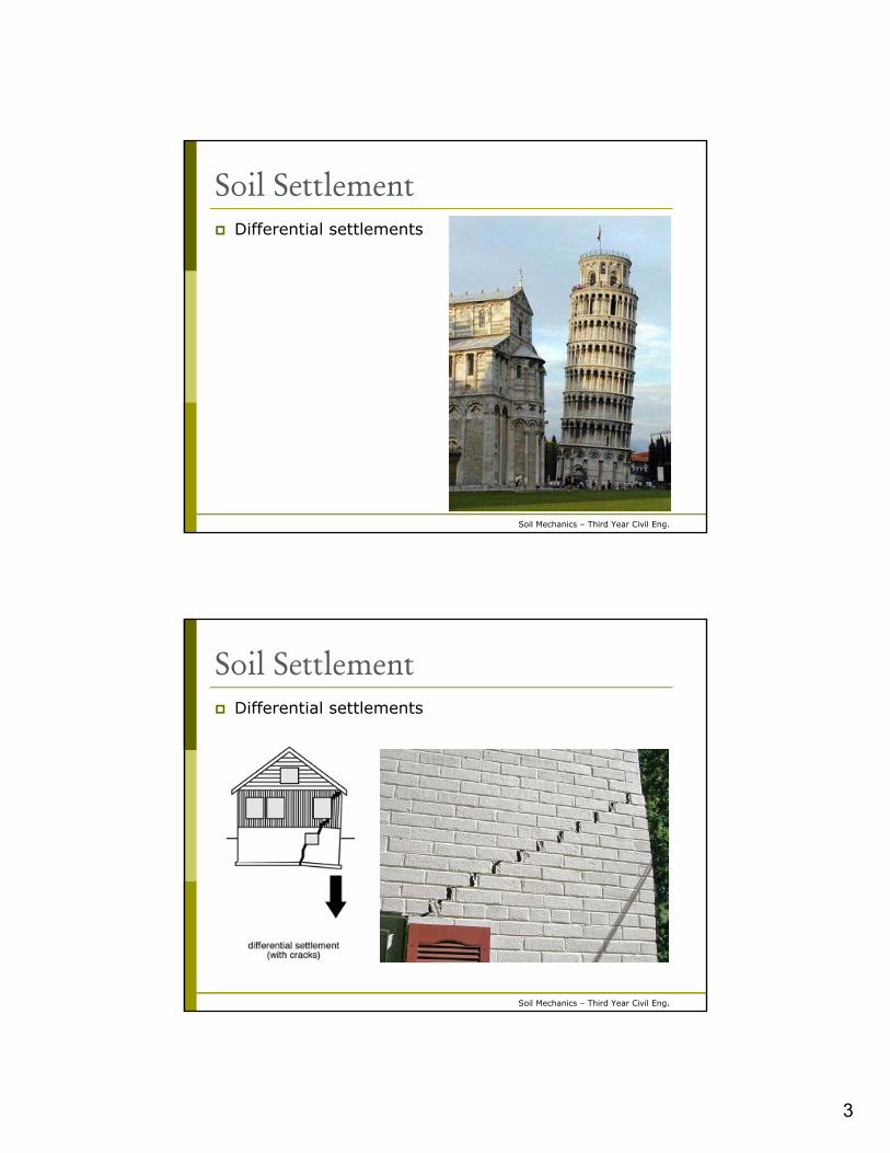
Soil Settlement Uniform settlements: equal settlements across the
area of the structure Differential settlements: unequally foundation
settlements in different areas of the structure. Differential settlement can result in severe structural
damage while uniform settlements are of less consequences
3
Soil Mechanics (PBW N302)Soil Mechanics – Third Year Civil Eng.
Soil Settlement Differential settlements
Soil Mechanics (PBW N302)Soil Mechanics – Third Year Civil Eng.
Soil Settlement Differential settlements
4
Soil Mechanics (PBW N302)Soil Mechanics – Third Year Civil Eng.
Define: Compressibility Compressibility: is the property through which
particles of soil are brought closer to each other, due
to escapage of air and/or water from voids under the
effect of an applied pressure.
Soil Mechanics (PBW N302)Soil Mechanics – Third Year Civil Eng.
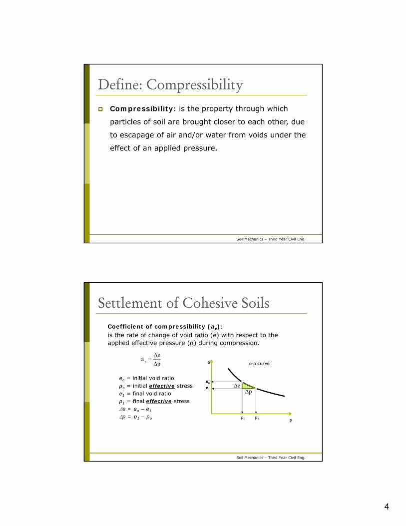
Settlement of Cohesive SoilsCoefficient of compressibility (av):is the rate of change of void ratio (e) with respect to the applied effective pressure (p) during compression.
p
ea v
e
p
ep
e-p curve
eo
e1
eo
e1
po p1
eo = initial void ratiopo = initial effective stresse1 = final void ratiop1 = final effective stresse = eo – e1
p = p1 – po

5
Soil Mechanics (PBW N302)Soil Mechanics – Third Year Civil Eng.
Settlement of Cohesive SoilsCoefficient of volume compressibility (mv):is the volume decrease of a unit volume of soil per unit increase of effective pressure during compression.
)e(1
a
Δp
Δe
)e(1
1
Δp
)Ve(1
ΔeV
Δp
VΔV
mo
v
o
so
s
ov
Initial Condition Final Condition
eoVs
Soil Mechanics (PBW N302)Soil Mechanics – Third Year Civil Eng.
Settlement of Cohesive SoilsFor a thin layer, p at mid depth is considered as an average stress within the layer.
)e(1
Δe
H
ΔH
o
V
V
1
eo
1+eo H
e H
H)e(1
Δp
ΔP
ΔeH)e(1
ΔeSΔH
oo
ΔpH)e(1
aS
o
v
H p
Clay
q
ΔpHmS v
where: S = settlementmv = coefficient of volume compressibilityp = stresses at mid depth of layer due to added loadsH = total thickness of layer

6
Soil Mechanics (PBW N302)Soil Mechanics – Third Year Civil Eng.
Settlement of Cohesive SoilsFor a thick layer, the layer may be divided to number of sub-layers, each of thickness Hi. The stress at mid-depth of each sub-layer is pi.
H1p1
Clay
q
iiHΔpmS vi
H2
p2
Soil Mechanics (PBW N302)Soil Mechanics – Third Year Civil Eng.
Settlement of Cohesionless Soils Sand may be considered as an elastic material with
Young’s modulus (E) Young’s Modulus (E): is the slope for the linear portion of
the stress-strain curve.
H p
Sand
q
E
1
stress
strain
EpH
H 1
E
p
H
S
pHE
1S
2kg/cm dense) (v. 800-loose) (v. 100E

7
Soil Mechanics (PBW N302)Soil Mechanics – Third Year Civil Eng.
ExampleCompute the settlement dueto compressibility of the sandand clay layers at points (a)and (b) of the building shownin the figure. The building hasa basement and is foundedon raft foundation. The stressfrom the building at thefoundation level is as shownin the figure.
Sand: = 1.70 t/m3 E = 500 kg/cm2
Clay: mv = 0.03 cm2/kg
Soil Mechanics (PBW N302)Soil Mechanics – Third Year Civil Eng.
Exampleqnet = q – h = 20 – 1.70x3.0 = 14.9 t/m2
For sand layer:
z = 5.0 m = 1” = 2.5 cm
L = 30 m 30x2.5/5.0 = 15.0 cm, B = 20 m 20x2.5/5.0 = 10.0 cm,
na = 191 a,sand = na/200 (qnet) = 191/200 x 14.9 = 14.2 t/m2
nb = 50 b,sand = nb/200 (qnet) = 50/200 x 14.9 = 3.7 t/m2
a b

8
Soil Mechanics (PBW N302)Soil Mechanics – Third Year Civil Eng.
Exampleqnet = q – h = 20 – 1.70x3.0 = 14.9 t/m2
For clay layer:
z = 11.0 m = 1” = 2.5 cm
L = 30 m 30x2.5/11 = 6.8 cm, B = 20 m 20x2.5/11 = 4.5 cm
na = 144 a,clay = n/200 (qnet) = 144/200 x 14.9 = 10.7 t/m2
nb = 47.3 b,clay = n/200 (qnet) = 47.3/200 x 14.9 = 3.5 t/m2
a b
Soil Mechanics (PBW N302)Soil Mechanics – Third Year Civil Eng.
Example
Sa = Ssand + Sclay
Ssand = 1/E a,sandH
H = 10.0 m E = 500 kg/cm2 a,sand = 14.2 t/m2
Ssand = 1/500 x 14.2/10 x 1000 = 2.84 cm
Sclay = mv a,clayH
H = 2.0 m mv = 0.03 cm2/kg a,clay = 10.7 t/m2
Sclay = 0.03 x 10.7/10 x 200 = 6.42 cm
Sa = Ssand + Sclay = 2.84 + 6.42 = 9.26 cm

9
Soil Mechanics (PBW N302)Soil Mechanics – Third Year Civil Eng.
Example
Sb = Ssand + Sclay
Ssand = 1/E b,sandH
H = 10.0 m E = 500 kg/cm2 b,sand = 3.7 t/m2
Ssand = 1/500 x 3.7/10 x 1000 = 0.74 cm
Sclay = mv b,clayH
H = 2.0 m mv = 0.03 cm2/kg b,clay = 3.5 t/m2
Sclay = 0.03 x 3.5/10 x 200 = 2.1 cm
Sb = Ssand + Sclay = 0.74 + 2.1 = 2.84 cm
Soil Mechanics (PBW N302)Soil Mechanics – Third Year Civil Eng.
Time of settlement compared to construction time Loading Diagram
Settlement of Sand
Settlement of Clay
Construction period Time
Time
Time
pHE
1S
ΔpHmS v
P
S
S

10
Soil Mechanics (PBW N302)Soil Mechanics – Third Year Civil Eng.
Causes of Settlement Static Loads
Dynamic Loads
Groundwater table lowering
Loads from adjacent buildings
Capillary forces
Soil Mechanics (PBW N302)Soil Mechanics – Third Year Civil Eng.
Theory of Consolidation Consolidation: is the process of squeezing water out
of saturated soil under the effect of loads.
In sandy soils, high permeability, drainage of water out
of the soil under the effect of loading happens
immediately.
In clay soils, low permeability, drainage of water out of
the soil under the effect of loading is time dependent.
Therefore, parameters governing consolidation process
include: soil properties, stress (p), time (t), drainage
conditions.

11
Soil Mechanics (PBW N302)Soil Mechanics – Third Year Civil Eng.
Mechanism of Consolidation Process
Analogy:
Confined saturated soil
(solids and voids filled
with water)
Versus
Container filled with
water that has a spring
and a valve
Remember: water is
incompressible
Valve ~ soil permeability
Spring ~ Solids
Water ~ pore-water
Piston for loading
Container
Soil Mechanics (PBW N302)Soil Mechanics – Third Year Civil Eng.
Mechanism of Consolidation Process
For Sands: high permeability ~ valve is open, water gets out
immediately (t = 0), excess pore water pressure u = 0
Stress = p
At t = 0 (immediately), u = 0Load carried by spring

12
Soil Mechanics (PBW N302)Soil Mechanics – Third Year Civil Eng.
Mechanism of Consolidation ProcessFor Clays: low permeability ~ valve is partially open, water
gets out slowly (time-dependent), u decreases with t
Stress = p
At t = 0 (immediately), u = pSpring carry no load
Stress = p
At t = t1, 0 u < pLoad carried by water and spring
Soil Mechanics (PBW N302)Soil Mechanics – Third Year Civil Eng.
Mechanism of Consolidation Process
For Clays:
Stress = p
Stress = p
At t = long time, u = 0Load carried by spring
At t = t1, 0 u < pLoad carried by water and spring

13
Soil Mechanics (PBW N302)Soil Mechanics – Third Year Civil Eng.
Mechanism of Consolidation Process If we apply a certain load, and the valve is closed, then
water (incompressible material) carries the entire added load.
If the valve is opened, water flows out, and thus its volume is reduced.
As volume is reduced, the spring starts to be compressed and carries part of the load. Meanwhile, excess pore water pressure decreases.
The process continues until sufficient amount of water escapes from the valve, resulting in compression of the spring to carry the entire load.
At this point, the excess pore water pressure decreases to zero, the spring carries the entire load, the system is in equilibrium.
Soil Mechanics (PBW N302)Soil Mechanics – Third Year Civil Eng.
Application on Soil Stress distribution before application of load
GSGWT
Sand
Clay
Gravel
tσ 'σu

14
Soil Mechanics (PBW N302)Soil Mechanics – Third Year Civil Eng.
Application on Soil Short time (immediately) after application of q (t = 0)
Sand
Clay
Gravel
tσ 'σu
q
q
q
q
q
GWT GS
Soil Mechanics (PBW N302)Soil Mechanics – Third Year Civil Eng.
Application on Soil Long time after application of q (t = h)
GWT
Sand
Clay
Gravel
tσ 'σu
q
q
q
q
GS

15
Soil Mechanics (PBW N302)Soil Mechanics – Third Year Civil Eng.
Application on SoilTotal stress:
Pore water pressure: t = 0 (clay)
(sand)
t = h (clay) (sand)
Effective stress: t = 0 (clay)
(sand)
t = h (clay) (sand)
qhΣγ'σ'
qhγu ww wwhγu
hΣγ'σ'
qΣγhσ t
wwhγu
wwhγu
qhΣγ'σ' qhΣγ'σ'
At time t ???
Soil Mechanics (PBW N302)Soil Mechanics – Third Year Civil Eng.
Rate of Consolidation
GSGWT
Sand
Clay
Gravel
tσ 'σu
q
q
q
q
q
t=0

16
Soil Mechanics (PBW N302)Soil Mechanics – Third Year Civil Eng.
Rate of Consolidation
Clay
q
u
t = 0t = t1
t = t3
t = t2
t = ∞
Soil Mechanics (PBW N302)Soil Mechanics – Third Year Civil Eng.
Assumptions of Theory of Consolidation
1. Clay is homogeneous, isotropic, and saturated
2. Water and clay particles are incompressible
3. Darcy’s law is valid
4. The clay layer is laterally confined
5. One-dimensional compression, and one-dimensional
flow
6. Consolidation parameters from test applies to clay
layer from which sample for test was taken7. Soil properties are constant with time

17
Soil Mechanics (PBW N302)Soil Mechanics – Third Year Civil Eng.
Consolidation Test
Objectives: Volume change-effective pressure relationship
Stress history of soil
Volume change – time – pore water dissipation relationship
Soil Mechanics (PBW N302)Soil Mechanics – Third Year Civil Eng.
Consolidation Test
Loading frame
Dial gauge
Compression cell
Load

18
Soil Mechanics (PBW N302)Soil Mechanics – Third Year Civil Eng.
Consolidation Test
Load
Dial gauge
Compression cell
Consolidation Test set-up
Lever Arm
Soil Mechanics (PBW N302)Soil Mechanics – Third Year Civil Eng.
Consolidation Test
Consolidation Test set-up
Dial gauge
Compression cell
Load = Po
Lever Arm
19
Soil Mechanics (PBW N302)Soil Mechanics – Third Year Civil Eng.
Consolidation Test
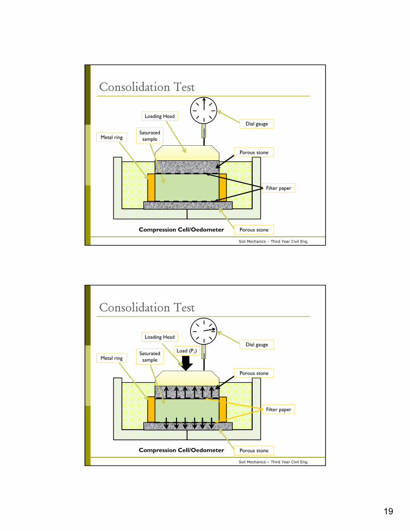
Compression Cell/Oedometer
Dial gauge
Porous stone
Porous stone
Saturated sampleMetal ring
Loading Head
Filter paper
Soil Mechanics (PBW N302)Soil Mechanics – Third Year Civil Eng.
Consolidation Test
Dial gauge
Porous stone
Porous stone
Saturated sampleMetal ring
Loading Head
Load (P1)
Filter paper
Compression Cell/Oedometer

20
Soil Mechanics (PBW N302)Soil Mechanics – Third Year Civil Eng.
Consolidation Test Equipment:
1. Compression cell / Oedometer
2. Loading frame to apply weights (Po)
3. Dial gage to measure soil compression
Note:
Load acting on the cell (P1) is magnified by the lever arm
ratio of the loading frame (LAR), where: P1 = LAR x Po
Soil Mechanics (PBW N302)Soil Mechanics – Third Year Civil Eng.
Consolidation Test Procedure:
1. Trim the sample into the metal ring and place filter paper
on both sides of sample.
2. Measure initial conditions of sample: ho, eo, wo, Gs
3. Place the ring into the compression cell between the two
porous stones.
4. A metal cap (loading head) is placed over the top porous
stone, on which the load (P1) is applied.
5. Set-up the dial gage to zero reading. Fill the compression
cell with water until the top porous stone is covered with
water.
21
Soil Mechanics (PBW N302)Soil Mechanics – Third Year Civil Eng.
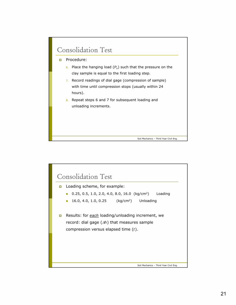
Consolidation Test Procedure:
6. Place the hanging load (Po) such that the pressure on the
clay sample is equal to the first loading step.
7. Record readings of dial gage (compression of sample)
with time until compression stops (usually within 24
hours).
8. Repeat steps 6 and 7 for subsequent loading and
unloading increments.
Soil Mechanics (PBW N302)Soil Mechanics – Third Year Civil Eng.
Consolidation Test Loading scheme, for example:
0.25, 0.5, 1.0, 2.0, 4.0, 8.0, 16.0 (kg/cm2) Loading
16.0, 4.0, 1.0, 0.25 (kg/cm2) Unloading
Results: for each loading/unloading increment, we
record: dial gage (h) that measures sample
compression versus elapsed time (t).

22
Soil Mechanics (PBW N302)Soil Mechanics – Third Year Civil Eng.
Consolidation Test Data Reduction For each loading increment, plot h-log t:
0
10
20
30
40
50
60
70
80
90
100
0.1 1 10 100 1000
h
(x
10
-2m
m)
Time (min)
Soil Mechanics (PBW N302)Soil Mechanics – Third Year Civil Eng.
Consolidation Test Data Reduction At the end of each loading increment:
1. Calculate effective pressure (p) = Load x LAR/sample area
2. Measure h = sample compression during this loading
increment
3. Calculate void ratio (e):
e = eo – e
Plot e-p curve
oo h
h
e
e
11
eo
1+eo ho
e h

23
Soil Mechanics (PBW N302)Soil Mechanics – Third Year Civil Eng.
Consolidation Test Data Reduction
232116582914.570Load (kg)
705550359223135890Dial Reading x 10-2 (mm) = h
16.638.324.162.081.047 x 3/41.85= 0.500Stress (p) = Load x lever arm
ratio/area (kg/cm2)
0.45410.35430.23120.14360.0870.89/25.4 (1+0.636)= 0.05730e = h/ho (1+eo)
0.18190.28170.40480.49240.54900.636-0.0573= 0.57870.636e = eo - e
Example: LAR = 3, sample area = 41.85 cm2, ho = 2.54 cm, eo = 0.636
Soil Mechanics (PBW N302)Soil Mechanics – Third Year Civil Eng.
Consolidation Test Data ReductionPlot e-p curve:
0
0.1
0.2
0.3
0.4
0.5
0.6
0.7
0 5 10 15 20
e
p (kg/cm2)
24
Soil Mechanics (PBW N302)Soil Mechanics – Third Year Civil Eng.
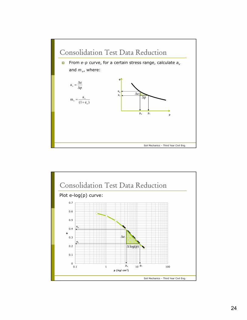
Consolidation Test Data Reduction From e-p curve, for a certain stress range, calculate av
and mv, where:
p
ea v
)e(1
am
o
vv
e
p
ep
eo
e1
po p1
Soil Mechanics (PBW N302)Soil Mechanics – Third Year Civil Eng.
Consolidation Test Data ReductionPlot e-log(p) curve:
0
0.1
0.2
0.3
0.4
0.5
0.6
0.7
0.1 1 10 100
e
p (kg/cm2)
e
p)log(
po p1
eo
e1

25
Soil Mechanics (PBW N302)Soil Mechanics – Third Year Civil Eng.
Consolidation Test Data Reduction From e-log(p) curve, the slope of the linear portion is the
Compression Index (Cc):
Determine preconsolidation pressure (pc): is the largest
effective pressure that has been applied on the soil in its
geological history.
)log( p
eCc
Soil Mechanics (PBW N302)Soil Mechanics – Third Year Civil Eng.
Consolidation Test Data ReductionDetermination of preconsolidation pressure:
0
0.1
0.2
0.3
0.4
0.5
0.6
0.7
0.1 1 10 100
e
p (kg/cm2)
1
2
3
4
5
pc
ba

26
Soil Mechanics (PBW N302)Soil Mechanics – Third Year Civil Eng.
Determination of Preconsolidation Pressure1. Determine point of maximum curvature (a).
2. At (a), draw tangent to e-log(p) curve.
3. At (a), draw horizontal line.
4. Draw a bisector to the angle enclosed between the
tangent and horizontal lines.
5. Extend the linear portion of the curve until it intersects
the bisector at point (b).
6. The preconsolidation pressure (pc) is the x-coordinate
of the point (b).
Soil Mechanics (PBW N302)Soil Mechanics – Third Year Civil Eng.
Types of clays w.r.t. preconsolidation1. Normally consolidated clay:
Clay that has never been loaded in the past by more than the
existing effective overburden pressure (po) pc ~ po
2. Overconsolidated (preconsolidated) clay:
Clay that has been loaded in the past by more than the existing
effective overburden pressure (po) pc > po
Causes: pre-existing structures, erosion of overburden
3. Underconsolidated clay:
Clay that has been loaded partially by the existing effectiveoverburden pressure (po) pc < po
o
c
p
pOCR
Define: Overconsolidation Ratio (OCR):

27
Soil Mechanics (PBW N302)Soil Mechanics – Third Year Civil Eng.
Determination of Compression Index For normally consolidated clays, Cc can be calculated as
follows:
From e-log(p) curve:
From liquid limit (empirical):
where wL is in (%)
)log( p
eCc
)10(009.0 Lc wC
Soil Mechanics (PBW N302)Soil Mechanics – Third Year Civil Eng.
0
0.1
0.2
0.3
0.4
0.5
0.6
0.7
0.1 1 10 100
e
p (kg/cm2)
Definitions
Recompression curve
Unloading/reloading curve
Virgin compression curve
pc

28
Soil Mechanics (PBW N302)Soil Mechanics – Third Year Civil Eng.
0
0.1
0.2
0.3
0.4
0.5
0.6
0.7
0.1 1 10 100
e
p (kg/cm2)
Definitions From e-log(p) curve, the recompression index (Cr) is the
slope of the equivalent linear portion of the
unloading/reloading curve.
)log( p
eCr
Cr
Cr
Cc
cr
cr
CC
CC
)8/1(
)5/110/1(
Empirical relationship for Cr:
Soil Mechanics (PBW N302)Soil Mechanics – Third Year Civil Eng.
Settlement Calculate settlement (S) of normally consolidated clay layer
of thickness (H) due to added stress (p) given Cc of clay:
)log( p
eCc
)log()log( 01
10
pp
eeCc
)log(0
1
ppe
Cc
1.................).........log(0
1
p
pCe c
2....................................1 H
S
h
h
e
e
oo
0
0.1
0.2
0.3
0.4
0.5
0.6
0.7
0.1 1 10 100
e
p (kg/cm2)p1
eo
e1
p (kg/cm2)
e Cc
pc ~ po
p

29
Soil Mechanics (PBW N302)Soil Mechanics – Third Year Civil Eng.
Settlement
From 1 and 2:
)1()log( 1o
oc e
H
S
p
pC
)log(1
1
oo
c
p
pH
e
CS
Soil Mechanics (PBW N302)Soil Mechanics – Third Year Civil Eng.
Settlement
For overconsolidated clay, (po and p1) < pc:
)log(1
1
oo
r
p
pH
e
CS
0
0.1
0.2
0.3
0.4
0.5
0.6
0.7
0.1 1 10 100
e
p (kg/cm2)p1
eo
e1
p (kg/cm2)
e
Cr
pc
p
po

30
Soil Mechanics (PBW N302)Soil Mechanics – Third Year Civil Eng.
Settlement
For overconsolidated clay, po < pc and and p1 > pc
)log(1
)log(1
1
co
c
o
c
o
r
p
pH
e
C
p
pH
e
CS
0
0.1
0.2
0.3
0.4
0.5
0.6
0.7
0.1 1 10 100
ep (kg/cm2)
p1
eo
e1
p (kg/cm2)e
Cr
pc
p
po
Cc
Soil Mechanics (PBW N302)Soil Mechanics – Third Year Civil Eng.
Rate of Consolidation
GSGWT
Sand
Clay
Gravel
tσ 'σu
q
p
Short time after application of load “q”
p
p
p

31
Soil Mechanics (PBW N302)Soil Mechanics – Third Year Civil Eng.
Rate of Consolidation
Clay
p
u
t = 0
1t = t
3t = t
2t = t
t = ∞
2H
p
u
t = 0
t = t
t = ∞Isochrone
Clay
Sand
Sand
zu '
Sand
Sand Hydrostatic pore water pressure (GWT)
At time “t” and depth “z”:p = u + ’ = increase in total stress due to added loadu = excess pore water pressure due to added load’ = increase in effective stress due to added load
Excess pore water pressure
Soil Mechanics (PBW N302)Soil Mechanics – Third Year Civil Eng.
Rate of Consolidation
Degree of Consolidation (Utz) at time “t” and depth “z”:
p
u
p
up
pUtz
1'
p
u
t = 0
t = tt = ∞
Clay
Sand
Sand
z u '
2H

32
Soil Mechanics (PBW N302)Soil Mechanics – Third Year Civil Eng.
Rate of ConsolidationAverage degree of consolidation (Ut) for the clay layer at time “t”:
Ut = (area of ’ diagram)/(area of p diagram)
Ut = (area of p diagram – area of u diagram)/(area of p diagram)
H
tzt dzUU0
2
p
up
pUtz
'
where:
p
u
t = 0
t = tt = ∞
Clay
Sand
Sand
z u '
2H
2HΔpdiagramΔpofarea
2Hu3
2diagramuofarea max
where:
umax
Soil Mechanics (PBW N302)Soil Mechanics – Third Year Civil Eng.
Settlement of clay layer of thickness 2H at time t=∞:
Sultimate = mvp(2H)
Settlement of clay layer of thickness 2H at time t=t:
St = mv’(2H)
St = mvp Ut)(2H) = Ut Sultimate
Average degree of consolidation (Ut) at time “t”:
Ut = St/Sultimate
The degree of consolidation at any time (t) is the percentage
of settlement that took place at this time w.r.t. to ultimate
consolidation settlement.
Rate of Consolidation

33
Soil Mechanics (PBW N302)Soil Mechanics – Third Year Civil Eng.
Differential equation of consolidation Equation governing rate of consolidation
Consider a differential element of soil
Surcharge load
ground surface
Qin
Qout
Area = dAVolume = dV
dxdz
dyxy
z
Soil Mechanics (PBW N302)Soil Mechanics – Third Year Civil Eng.
Differential equation of consolidation
kidAQ
dzz
QQQ
t
dVinout )(
)(
dAz
hk
compression and flow 1-D
dAu
zk
w
)(
dAz
uk
w
Darcy’s law is valid
u = excess p.w.p
dzdAz
uk
zt
dV
w
)()(
dVz
uk
t
dV
w2
2)(
Equation (1) soil is homogeneous
Qin
Qout
Area = dAVolume = dV
dxdz
dy
xy
z

34
Soil Mechanics (PBW N302)Soil Mechanics – Third Year Civil Eng.
Differential equation of consolidation
e
e
dV
dVv
1
t
dV
t
dV v
)()(
dVe
edVv
1 dVv
dVs
dV
1
e
edV
dVs
1
1dV
edVs
1
1
e
dV
t
edV
t
e
t
edV
t
dVe
e
t
dV
t
dVs
sv
1
)()1
()()(
e
dV
t
e
t
dV
1
)(
From equations 1 and 2,
e
dV
t
edV
z
uk
w
12
2
Equation (2)
Soil Mechanics (PBW N302)Soil Mechanics – Third Year Civil Eng.
Differential equation of consolidation
t
e
z
uek
w
2
2)1(
t
e
t
e
'
'
t
ua
t
u
ta
t
evv
)(
(chain rule)
ta
t
ev
'
':
e
av
0:
t
(load doesn’t vary with time)
t
ua
z
uekv
w
2
2)1(
2
2)1(
z
u
a
ek
t
u
wv
2
2
z
uc
t
uv
wvwvv m
k
a
ekc
)1(:
p
u
t = 0
t = tt = ∞
Clay
Sand
Sand
z u '
2H umax

35
Soil Mechanics (PBW N302)Soil Mechanics – Third Year Civil Eng.
Coefficient of Consolidation: cv
Differential equation of consolidation
where:k = soil permeabilitymv = coefficient of volume compressibility
wvv m
kc
cm2/sec
Soil Mechanics (PBW N302)Soil Mechanics – Third Year Civil Eng.
Boundary conditions:Example: a clay layer, of thickness 2H, with top and bottom boundaries freely draining
u(z=0,t>0) = 0 u(z=2H,t>0) = 0
Initial condition:For wide fill, applied instantly to saturated soil, the initial excess pore-water pressure u(z,t=0) is independent of depth and equals the applied stress (p)
u(z,t=0) = ui = p
Solution of differential equation of consolidation
Sand
Sand
Clay
u
t = t1
t = t2z
as time increases, u decreases2H

36
Soil Mechanics (PBW N302)Soil Mechanics – Third Year Civil Eng.
Solution:
……………… Equation 3
where:
Tv = Time factor
Solution of differential equation of consolidation
)exp()(sin2
),( 2
0v
m
i TMMZM
utzu
)12(2
mM
2H
tcT v
v
Soil Mechanics (PBW N302)Soil Mechanics – Third Year Civil Eng.
Equation (3) was solved chart: u/p = f(Tv, z)
Solution of differential equation of consolidation

37
Soil Mechanics (PBW N302)Soil Mechanics – Third Year Civil Eng.
Solution in terms of degree of consolidation (U):
Average degree of consolidation for entire layer:U = area / area By integration:
Solution of differential equation of consolidation
)exp()(sin2
1),( 2
0v
m
TMMZM
tzU
ii
i
u
u
u
uutzU
1),(
i
H
t u
udz
U
2
01
u
z
t = t2H
ui
u ui-uz
)exp()(sin2
),( 2
0v
m
i TMMZM
utzu
)TMexp(M
U vm
t2
02
21
Soil Mechanics (PBW N302)Soil Mechanics – Third Year Civil Eng.
Equation (4) was solved Table and chart: Tv = f(U)
Solution of differential equation of consolidation
0
10
20
30
40
50
60
70
80
90
100
0 0.2 0.4 0.6 0.8 1 1.2
U (%)
Tv
10099959080706050403020100U (%)
∞1.7811.1290.8480.5670.4030.2870.1970.1260.0710.0310.0080.0Tv

38
Soil Mechanics (PBW N302)Soil Mechanics – Third Year Civil Eng.
Time Factor: Tv
Solution of differential equation of consolidation
2d
vv h
tcT
where:Tv = time factor corresponding to degree of consolidation occurring at time tcv = coefficient of consolidation (determined from consolidation test)hd = longest drainage path within clay layer
The above equation holds for consolidation of sample in the lab, and for clay layer consolidating in the field
Soil Mechanics (PBW N302)Soil Mechanics – Third Year Civil Eng.
Drainage Path: hd
Solution of differential equation of consolidation
2H Clay
Sand
Sand
2H Clay
Impervious Rock
Sand
hd = H hd = 2H

39
Soil Mechanics (PBW N302)Soil Mechanics – Third Year Civil Eng.
Determination of cv - logarithm-of-time method cv is determined from the consolidation test data
There is a cv value that corresponds to each loading increment, i.e. cv is stress dependent.
Two methods to calculate cv:
Logarithm-of-time method
Square–root-of-time method
For the following test data corresponding to a certain loading increment, find cv.
885240120603015106.2542.2510.50.250Time (min)
223221220219215209202193184173161155153135Dial Reading x 10-2
(mm)
888685848074675849382620153-135=18
135-135= 0= h x 10-2 (mm)
885240120603015106.2542.2510.50.250Time (min)
223221220219215209202193184173161155153135Dial Reading x 10-2
(mm)
888685848074675849382620153-135=18
135-135= 0= h x 10-2 (mm)
Soil Mechanics (PBW N302)Soil Mechanics – Third Year Civil Eng.
0
10
20
30
40
50
60
70
80
90
100
0.1 1 10 100 1000
h
(x
10
-2m
m)
Time (min)
U = 0%
U = 100%
t50 = 3.6 min
t = t1 t = 4t1
U = 50%
Determination of cv - logarithm-of-time method

40
Soil Mechanics (PBW N302)Soil Mechanics – Third Year Civil Eng.
1. Plot the (h) or (e) on the vertical axis (arithmetic scale), and the
time (t) on horizontal axis (logarithmic scale) S-shape
2. Determine (h) or (e) corresponding to 100% consolidation:
Extrapolate the linear portion at the middle of the consolidation curve
Extrapolate the linear portion at the end of the consolidation curve
The two lines intersect at a point corresponding to (h) or (e) at 100%
consolidation
3. Determine (h) or (e) corresponding to 0% consolidation:
Consider (h1) corresponding to a small time (t1)
Consider (h2) corresponding to (4t1)
Determine the difference between (h1) and (h2) y
Determine (h) corresponding to 0% consolidation at a distance equivalent
to y above (h1)
Determination of cv - logarithm-of-time method
Soil Mechanics (PBW N302)Soil Mechanics – Third Year Civil Eng.
4. Determine (h) or (e) corresponding to 50% consolidation at mid
distance between 0% consolidation and 100% consolidation.
5. Determine t50
6. Calculate cv:
where: T50 = 0.197, hd = ½ sample height (sample drains from both
sides), and t = t50 from consolidation curve
2d
vv h
tcT
Determination of cv - logarithm-of-time method

41
Soil Mechanics (PBW N302)Soil Mechanics – Third Year Civil Eng.
0
10
20
30
40
50
60
70
80
90
100
0 5 10 15 20 25 30 35
Square root time (min)0.5
h
(x
10-2
mm
)
Determination of cv – square root-of-time method
U = 0%
(t90)0.5
x
U = 90%
0.15x
a
c
b
Soil Mechanics (PBW N302)Soil Mechanics – Third Year Civil Eng.
1. Plot the (h) or (e) on the vertical axis (arithmetic scale), and the square
root of time on horizontal axis (arithmetic scale)
2. Determine (h) or (e) corresponding to 90% consolidation:
Draw a straight line through the initial linear portion of the curve. This line will
intersect the vertical axis at a point (a) that corresponds to U = 0%
Measure distance (x) between the vertical axis and the drawn line
Measure additional distance (0.15x) point (b)
Draw a line connecting points (a) and (b) and extend it until it intersects the
original curve at point (c) corresponds to U = 90%
3. Determine (t90)0.5
Determination of cv – square root-of-time method

42
Soil Mechanics (PBW N302)Soil Mechanics – Third Year Civil Eng.
4. Calculate cv:
where: T90 = 0.848, hd = ½ sample height (sample drains from both
sides), and t = t90 from consolidation curve
290
90d
v
h
tcT
Determination of cv – square root-of-time method
Soil Mechanics (PBW N302)Soil Mechanics – Third Year Civil Eng.
Types of Compression
0
10
20
30
40
50
60
70
80
90
100
0.1 1 10 100 1000
h
(x
10
-2m
m)
Time (min)
U = 0%
U = 100%
Primary Consolidation
Secondary Consolidation
Instantaneous/Immediate Consolidation
h = 0

43
Soil Mechanics (PBW N302)Soil Mechanics – Third Year Civil Eng.
Types of Compression
1. Instantaneous/Immediate Compression: due to
compression of entrapped air and machine parts
2. Primary Compression: due to consolidation by
escapage of water (relief of excess pore-water
pressure) under the effect of pressure (loading)
3. Secondary compression: compression at constant
effective stress (no excess pore-water pressure)
Soil Mechanics (PBW N302)Soil Mechanics – Third Year Civil Eng.
Secondary Compression Index
0
10
20
30
40
50
60
70
80
90
100
0.1 1 10 100 1000
h
(x
10
-2m
m)
Time (min)
U = 100%
t100
hlog(t)

44
Soil Mechanics (PBW N302)Soil Mechanics – Third Year Civil Eng.
Secondary Consolidation Settlement (Ss) Secondary compression index (C):
Secondary settlement (Ss):
)log(t
eC
)1( oeH
he
where:
)log(1
1
oos t
tH
e
CS
Soil Mechanics (PBW N302)Soil Mechanics – Third Year Civil Eng.
ExampleA rectangular building 24m 16m is
founded on a raft and has its
foundation level at 2.0 m below ground
surface. If the building exerts a net
stress of 2.0 kg/cm2 on soil at
foundation level, determine:
i.The ultimate settlement of points a, b
and c.
ii.The time required for these points to
settle 5.0 cm, and the time required to
undergo 90% consolidation.
(a) (c) (b)
Sand

45
Soil Mechanics (PBW N302)Soil Mechanics – Third Year Civil Eng.
Examplei. qnet = 20 t/m2
z = 8.0 m
H = 5.0 m
Using Influence Chart:
ca & bPoints
1224L (m)
88B (m)
1.53m
11n
0.2030.193Iz
0.203x20x4 = 16.240.193x20x2 = 7.72(t/m2)
0.004x16.24x5 = 0.325 m
0.004x7.72x5 = 0.154 m
S = mv H
Soil Mechanics (PBW N302)Soil Mechanics – Third Year Civil Eng.
Exampleii.
cv = 0.006 cm2/sec
bcaPoints
=5/15.4 = 0.3255/32.5 = 0.154=5/15.4 = 0.325U = St/Sf
0.0830.0190.083From Chart(Tv)
40.09.210.0t (days)
(a) (c) (b)
2D
vv h
tcT
2(500)
t0.006019.0
2(250)
t0.006083.0 2(500)
t0.006083.0

46
Soil Mechanics (PBW N302)Soil Mechanics – Third Year Civil Eng.
Exampleii.
cv = 0.006 cm2/sec
bcaPoints
0.900.900.90U = St/Sf
0.8480.8480.848From Chart(Tv)
409.0409.0102.2t (days)
0.90 x 15.4 = 13.9 cm0.90 x 32.5 = 29.3 cm0.90 x 15.4 = 13.9 cmSt (cm)
(a) (c) (b)
2D
vv h
tcT
2(500)
t0.006848.0 2(250)
t0.006848.0
2(500)
t0.006848.0
Example
Soil Mechanics (PBW N302)Soil Mechanics – Third Year Civil Eng.
Potential Sources of Error Sample disturbance: due to improper handling and/or
trimming. Disturbance affects e-logp curve, and thus
preconsolidation pressure. Larger samples help reduce
effect of trimming on sample disturbance.
Kontopoulos, Nikolaos S., 2012

47
Soil Mechanics (PBW N302)Soil Mechanics – Third Year Civil Eng.
Potential Sources of Error Specimen not completely filling the ring: erroneous
volume change due to compression of voids.
Clogged porous stones: porous stones should be
cleaned after every test to remove embedded soil
particles.
Friction between specimen and consolidation ring. Part
of load applied to specimen can be lost by side friction.
This effect can be reduced by lining the consolidation
ring with Teflon.