software examples to showcase unique capabilities of ti s
TRANSCRIPT

1SPRACS0–May 2020Submit Documentation Feedback
Copyright © 2020, Texas Instruments Incorporated
Software Examples to Showcase Unique Capabilities of TI’s C2000™ CLA
Application ReportSPRACS0–May 2020
Software Examples to Showcase Unique Capabilities ofTI’s C2000™ CLA
Himanshu Chaudhary and Aravindhan Karuppiah
ABSTRACTEnabling extremely high performance computation and efficient processing is critical for solving today’scomplex real-time control problems. Real-time control systems are closed-loop control systems where onehas a tight time window to gather data, process that data, and update the system in order to meet theperformance objectives. TI’s Control Law Accelerator (CLA) is designed to execute real-time controlalgorithms in parallel with the C28x CPU, effectively doubling the computational performance of C2000devices. This application report discusses some of the unique features of CLA and demonstrates themusing simple software examples. These stand-alone examples are available as part of C2000Ware andcan be quickly used to explore and evaluate the capabilities of CLA.
Contents1 Introduction ................................................................................................................... 22 Direct Access of CLA to Key Peripherals................................................................................. 23 Low interrupt Latency of CLA .............................................................................................. 44 Powerful Math Computation Capability of CLA .......................................................................... 75 Offloading Fast Control Loop to CLA ..................................................................................... 86 Summary .................................................................................................................... 137 References .................................................................................................................. 14
List of Figures
1 Direct PWM Control Using CLA ........................................................................................... 32 Interrupt vs Task Driven Machine ......................................................................................... 43 Early Interrupt From ADC to Trigger CLA Task ......................................................................... 54 CLA Pipeline Activity for Early Interrupt Pulse ........................................................................... 55 “Just-in-time” ADC Read Example Showcase .......................................................................... 66 Dual Control Loop Example Showcase................................................................................... 87 Flow Diagram With Both Tasks Running on C28x ...................................................................... 98 Profiling Waveforms for Both Tasks Running on C28x ................................................................. 99 Flow Diagram With Loop 1 Task Offloaded to CLA ................................................................... 1010 Profiling Waveforms for Loop1 Task Offloaded to CLA ............................................................... 1011 Concurrent R-M-W by C28x/CLA ........................................................................................ 1112 Profiling and Output Waveforms With Phase-Shift Disabled ......................................................... 1113 EPWM-Based Phase-Shifting Technique ............................................................................... 1214 Profiling and Output Waveforms With Phase-Shift Enabled.......................................................... 12
List of Tables
1 CLA Math and Control Library Routines .................................................................................. 7

Introduction www.ti.com
2 SPRACS0–May 2020Submit Documentation Feedback
Copyright © 2020, Texas Instruments Incorporated
Software Examples to Showcase Unique Capabilities of TI’s C2000™ CLA
TrademarksC2000 is a trademark of Texas Instruments.All other trademarks are the property of their respective owners.
1 IntroductionThe CLA is a fully-programmable independent 32-bit floating-point CPU that is designed for optimal mathintensive computations to offer a significant boost to the performance of control algorithms. Unlike thestandard traditional processor which executes instructions and services interrupts, the CLA instead is atask-driven machine and can support up to 8 user-defined tasks. The CLA in addition to providingcomputational capability provides an unique combination of minimal latency and ease of access to the keycontrol peripherals. This makes the CLA ideal for implementing fast control loops, thus freeing upbandwidth on C28x to run additional control loops and perform other diagnostic and communicationrelated tasks. The subsequent sections of this application report discusses these unique capabilities ofCLA in detail and also demonstrates them through simple software examples which are provided as partof C2000Ware package [2]. For more details on CLA architecture and instructions set, see [1], [3].
The examples discussed in this document can be found in C2000Ware v3.01.00.00 or latest, locatedwithin the following directories after installation:• C:\ti\c2000\C2000Ware_<version_number>\driverlib\f28004x\examples\cla• C:\ti\c2000\C2000Ware_<version_number>\libraries\math\CLAmath\c28\examples• C:\ti\c2000\ C2000Ware_<version_number>\libraries\control\DCL\c28\examples
The discussed example projects are:• cla_ex4_pwm_control• cla_ex5_adc_just_in_time• cla_ex6_cpu_offloading• cla_ex7_shared_resource_handling
2 Direct Access of CLA to Key PeripheralsMost of the real-time control algorithms can be split into three main tasks: excite the system, sample thesystem and control the system. Exciting the system would involve updating the PWM registers, samplingthe system involves accessing the ADC result registers while controlling the system involves control loopmath computations. CLA being an independent math processor, also has the ability to access registers ofall key peripherals used for control applications like EPWM, ADC, ECAP, EQEP, CMPSS, and so forthdirectly. This allows CLA to perform sampling and actuation along with computation of control logic and iscapable of executing the entire control task independently without any C28x involvement.
The example “cla_ex4_pwm_control” showcases how to control the PWM signal output directly throughCLA. The block diagram of this example is shown in Figure 1. In this example, EPWM1 is configured togenerate complementary signals on both of its channels at a fixed frequency of 100 KHz while EPWM4 isconfigured to trigger a periodic CLA control task at a frequency of 10 KHz. The CLA Task 1 implements avery simple logic to vary the duty of the EPWM1 outputs by increasing it by 0.1 for every iteration whilemaintaining it in the range of 0.1-0.9. The code sequence below illustrates how the existing C28x driverlibAPIs (available as part of C2000Ware) can be used as it is within the CLA task to update the EPWMregisters avoiding any additional software development effort with respect to CLA. The CLA task canaccess key registers of other shared peripherals as well in a similar fashion. Note that the CLA globalvariables cannot be initialized at the start of .cla file thus this example also illustrates a systematic way ofinitializing all the CLA global variables inside a dedicated CLA task (CLA task 8), which is triggered byC28x software at the time of initialization.

CLATask
EPWM4 @ 10 KHz
EPWM1100 KHz PWM variable duty signal
www.ti.com Direct Access of CLA to Key Peripherals
3SPRACS0–May 2020Submit Documentation Feedback
Copyright © 2020, Texas Instruments Incorporated
Software Examples to Showcase Unique Capabilities of TI’s C2000™ CLA
Figure 1. Direct PWM Control Using CLA
__attribute__((interrupt)) void Cla1Task1 ( void ){
//// Uncomment this to debug the CLA while connected to the debugger//__mdebugstop();
//// Write to the COMPA register to realize a particular duty value//EPWM_setCounterCompareValue(EPWM1_BASE, EPWM_COUNTER_COMPARE_A,
(uint16_t)(duty * EPWM1_PERIOD + 0.5f));
//// Update duty value and use the limiter//duty += 0.1f;duty = (duty > 0.9f) ? 0.1f : duty;
//// Clear EPWM4 interrupt flag so that next interrupt can come in//EPWM_clearEventTriggerInterruptFlag(EPWM4_BASE);
}

Low interrupt Latency of CLA www.ti.com
4 SPRACS0–May 2020Submit Documentation Feedback
Copyright © 2020, Texas Instruments Incorporated
Software Examples to Showcase Unique Capabilities of TI’s C2000™ CLA
3 Low interrupt Latency of CLAIn any real-time control application, the sample to output delay, defined as the time that elapses betweensensing, processing and actuation, is an important system consideration. The low-latency architecture ofCLA reduces this sample to output time while increasing the overall system throughput. This is madepossible because CLA is task oriented instead of interrupt driven machine and does not use interrupts tosynchronize with hardware. Instead, it supports up to eight independent tasks, which are each mapped tohardware events such as a timer or data availability on an ADC, and so forth. A task initiated on the CLAruns to completion without any interruption or nesting involved, hence eliminating the need for anycontext-switching overhead typically involved in traditional interrupt-based processors. Thus, there is littleto no delay involved in processing the data by CLA, which ultimately reduces the sample to output delayand enables faster system response. Figure 2 illustrates the differences between a task driven machine(TDM) and an interrupt driven machine (IDM).
Figure 2. Interrupt vs Task Driven Machine

Sampling Conversion
Pre-processing Read Processing + Update
Early
Interrupt
Pulse
³-XVW-In-7LPH´�
ADC Read
ADC Activity
CLA Activity
CLA Task
Begins
CLA Task
Completes
www.ti.com Low interrupt Latency of CLA
5SPRACS0–May 2020Submit Documentation Feedback
Copyright © 2020, Texas Instruments Incorporated
Software Examples to Showcase Unique Capabilities of TI’s C2000™ CLA
The low interrupt response of CLA can be leveraged in combination with the early-interrupt feature of TI’sinternal ADC to further reduce the sample to output delay. The ADC can be configured to generate anearly interrupt pulse at the end of sampling before the conversion completes. This early-interrupt pulsefrom the ADC can be used to trigger a CLA task that would allow the CLA to read the result as soon asthe conversion result is available in the ADC result register. This combination of just-in-time samplingalong with the low interrupt response of the CLA enable faster system response and higher frequencycontrol loops. The available time before the conversion can be effectively utilized for any necessary pre-processing steps within the CLA task as illustrated in Figure 3. The exact instruction at which the readrequest should be placed to achieve just-in-time read can be calculated based on the CLA pipeline activityfor N-cycle ADC conversion. As shown in Figure 4, The N-2 instruction will arrive in the R2 phase just intime to read the result register. For the standard 12-bit ADC configuration and clock divider as 4, N is 42.To find out the correct value of N based on the configuration of ADC, see the device-specific data sheet[4].
Figure 3. Early Interrupt From ADC to Trigger CLA Task
Figure 4. CLA Pipeline Activity for Early Interrupt Pulse

CLA
EPWM1 @ 1 MHz
EPWM1Linear Mapping
CLA Task(Just-in-time
Read + Processing)
EarlyInterrupt
Low interrupt Latency of CLA www.ti.com
6 SPRACS0–May 2020Submit Documentation Feedback
Copyright © 2020, Texas Instruments Incorporated
Software Examples to Showcase Unique Capabilities of TI’s C2000™ CLA
The example “cla_ex5_adc_just_in_time” utilizes the above concept to read the ADC data “just-in-time”even at very high sampling frequencies. As depicted in Figure 5, EPWM1 is configured to generate aPWM output signal of frequency 1 MHz, which is also used to trigger the ADC sampling at each cycle. Theexample also utilizes the newly added feature in TI’s Type 5 ADCs, which allows delaying the earlyinterrupt pulse by few cycles as per the programmed OFFSET value. Thus ADCA is configured to samplethe input on Channel 0 and to generate the early interrupt at the end of S/H + offset cycles. This interruptis used to trigger the CLA control task. The CLA task implements the control logic to update the duty ofthe PWM output based on the read ADC value. The early interrupt feature and low interrupt latency ofCLA allows the application to do any necessary pre-work so that the application can act on the ADCresults immediately when they become available and still complete updating the PWM output before thenext interrupts arrives. Thus, all the three steps (sampling, processing and actuation) are completed withina 1 MHz cycle. As shown in the below code snippet of the CLA task, 3-point moving average filter is usedto simulate the processing sequence for illustration purposes and few steps of the filtering sequence thatare denoted as the pre-processing code are implemented before reading the ADC result to make use ofthe time available before conversion.
Figure 5. “Just-in-time” ADC Read Example Showcase
//// Pre-processing for implementing moving average filter, takes 13 cycles// This is just to illustrate how cycles can be utilized to do some pre-// processing before ADC result latches. Based on the cycles taken by// pre-processing code, ADC interrupt offset need to be programmed//data_read_total = data_read + data_read_prev;data_read_prev2 = data_read_prev;data_read_prev = data_read;
//// Reading ADC just-in-time//data_read = HWREGH(ADCARESULT_BASE + ADC_RESULTx_OFFSET_BASE + ADC_SOC_NUMBER0);
//// "data_read_total" stores the cumulative sum of current and last 2 data elements//data_read_total += data_read;
//// Taking average of 3 elements, normalizing for 12-bit and mapping to output duty// linearly in the range 0.1-0.9// duty = 0.1 + (0.9-0.1) * ((data_read_total / 3) / 2^12 )//duty = 0.1f + (data_read_total / (15360.0f));
//// Writing to the COMPA register for realizing computed duty value//HWREGH(EPWM1_BASE + EPWM_O_CMPA + 0x1U) = (uint16_t)(duty * EPWM1_PERIOD + 0.5f);

www.ti.com Powerful Math Computation Capability of CLA
7SPRACS0–May 2020Submit Documentation Feedback
Copyright © 2020, Texas Instruments Incorporated
Software Examples to Showcase Unique Capabilities of TI’s C2000™ CLA
The early interrupt OFFSET value of ADC need to be adjusted based on the cycles consumed by the pre-processing in order to read the ADC data “just-in-time”. In this example, the OFFSET value of 20 is usedbased on the calculation shown in example header. The programming sequence for this configuration ofADC is shown below. The actual use-case may involve different pre-processing steps, hence the interruptOFFSET value need to programmed accordingly.
//// Set pulse positions to early//ADC_setInterruptPulseMode(ADCA_BASE, ADC_PULSE_END_OF_ACQ_WIN);
//// Set interrupt offset delay as 20 cycles based on the calculation// shown in example header//ADC_setInterruptCycleOffset(ADCA_BASE, 20);
4 Powerful Math Computation Capability of CLACLA also offers powerful 32-bit floating point processing capability to C2000 devices and provides asignificant boost to the performance of typical math functions that are commonly used in controlalgorithms. The powerful CLA instruction set supports floating point multiplication with parallel add orsubtract operations in a single cycle and also supports computation of inverse square root in a single cycletoo. For the ease of software development with CLA, a wide collection of commonly used floating-pointmath functions (a few of them are listed in Table 1) are packaged into a single library called as CLA Math,which is available as part of C2000Ware. This source code library includes several C callable assemblymath functions optimally written for CLA architecture.
In addition to the basic math routines, TI also provides Digital Control library (DCL available as part ofC2000Ware) that includes optimal implementation of standard control routines on CLA CPU, few of themare listed in Table 1. These C callable assembly control routines can be called within a CLA applicationtask to realize digital controller on CLA CPU. Along with the library source code, examples are provided toshow the user how to integrate the library into their projects and use any of the math or control routines.These examples can be found in the example directories indicated in the introduction section that can beused to explore and evaluate the compute capability of CLA.
Table 1. CLA Math and Control Library Routines
Library Routine Description CyclesCLA Math CLAcos Calculates cosine on CLA 28
CLAsin Calculates sine on CLA 28CLAacos Calculates arc-cos on CLA 24CLAasin Calculates arc-sine on CLA 22CLAatan Calculates arc-tan on CLA 41CLAlog10 Calculates Log (base10) on CLA 29CLAexp Calculates exponential on CLA 41CLAdiv Calculates floating-point division on CLA 13
CLAisqrt Calculates inverse square root on CLA 14CLAsqrt Calculates square root on CLA 16
DCL DCL_runPID_L1 Runs Ideal Form PID controller on CLA 53DCL_runPID_L2 Runs Parallel Form PID controller on CLA 45DCL_runPI_L1 Runs Ideal Form PI controller on CLA 34
DCL_runDF13_L1 Runs the DF13 Full Compensator on CLA 61DCL_runDF13_L2 Runs the DF13 Immediate Compensator on CLA 20DCL_runDF13_L3 Runs the DF13 Partial Compensator on CLA 58

EPWM5 @ 20 KHz
ADCB
SOC0
SOC1
SOC2
SOC3
V2
CLA
SOC0
SOC1
SOC2
SOC3
EPWM4 @ 200 KHz
V1Loop1 DCL_PI
Controller
Loop2 DCL_PI
Controller
EPWM1V1_ref
V2 _ref
0.8
0.2
PWM+
Offloading Fast Control Loop to CLA www.ti.com
8 SPRACS0–May 2020Submit Documentation Feedback
Copyright © 2020, Texas Instruments Incorporated
Software Examples to Showcase Unique Capabilities of TI’s C2000™ CLA
5 Offloading Fast Control Loop to CLAVarious real-time control applications involve implementation of multiple control loops on a single device.However integration of multiple control systems on a single controller remains challenging from aprocessor bandwidth point of view while keeping system costs down. The CLA is a fully parallel processorto the main C28x core that brings concurrent control-loop execution to the C28x family. The CLA has itsown program and data bus, and executes independently of the main core on the MCU. As described inSection 2 and Section 3, CLA provides unique combination of minimal latency and ease of access to thekey control peripherals, which enables CLA to offload the fast control algorithm task entirely from C28x.Offloading the control task to CLA also offers additional benefits such as reduced jitter in execution anddeterministic operation of control loops. This is made possible because the CLA is task oriented instead ofan interrupt service driven machine and the tasks on CLA cannot be interrupted guaranteeing thedeterministic nature of control loops. In a pipelined CPU, the ISRs can be delayed by an “n” number ofcycles if the CPU is executing branch type statements when the ISR is received. However this is not aproblem with CLA CPU as it waits in an idle state till the periodic task triggers to begin any execution dueto its task-driven nature. Therefore, offloading fast control task to CLA and running remaining tasks onC28x helps to improve the overall system performance with reduced jitter in execution.
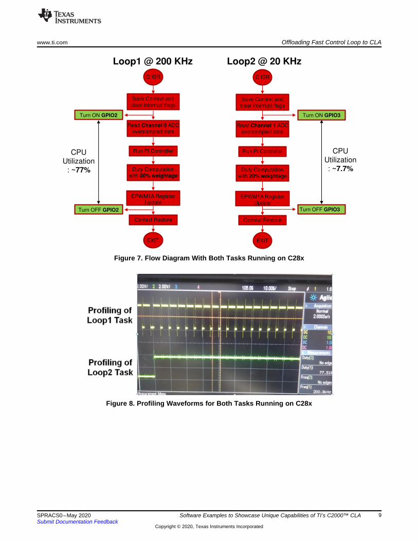
The example “cla_ex6_cpu_offloading” illustrates how to optimally offload a control loop from C28x to CLAwhen multiple control tasks and background tasks are involved which require more than single CPU(C28x) bandwidth. Figure 6 shows that two control loops are simulated in this example. The faster one(loop1) runs at 200 KHz while the slower one (loop2) runs at 20 KHz. Both the loops make use of PIcontroller to control the duty of single PWM output with different weightage, the faster one contributionbeing 80% while the slower one contributes 20% to the PWM output. The inputs for both the loops aresampled using ADCA and ADCB with multiple SOCs for each to filter out any noise in the inputs. There isalso a background task continuously running in the main loop that disables or enables the entire systemincluding the PWM output and the control loops based on the user configured switch "system_OFF". Notethat the CCS debugger clock cannot be used for profiling CLA routines, hence GPIO based profilingtechnique is employed in this example to profile the both tasks. GPIO2 and GPIO 3 have been used forthis purpose.
Figure 7 depicts the flow diagram of both the control tasks when everything runs on C28x without the useof CLA. In this case, the total CPU (C28x) utilization exceeds the schedulable Utilization bound (UB) and,hence the system is schedulable in this scenario. This can also be further substantiated by observing theprofiling waveforms shown in Figure 8. Note that there is no toggling observed on GPIO3, which clearlysuggests that the lower priority Loop 2 task never gets chance to complete and neither the backgroundtask.
Figure 6. Dual Control Loop Example Showcase
lective Disclosure
C ISR
Save Context and
clear interrupt flags
Read Channel 0 ADC
oversampled data
Run PI Controller
Duty Computation
with 80% weightage
EPWM1A Register
Update
EXIT
Loop1 @ 200 KHz Loop2 @ 20 KHz
Context Restore
C ISR
Save Context and
clear interrupt flags
Read Channel 1 ADC
oversampled data
Run PI Controller
Duty Computation
with 20% weightage
EPWM1A Register
Update
EXIT
Context Restore
Turn ON GPIO2
Turn OFF GPIO2
Turn ON GPIO3
Turn OFF GPIO3
CPU Utilization
: ~77%
CPU Utilization : ~7.7%
www.ti.com Offloading Fast Control Loop to CLA
9SPRACS0–May 2020Submit Documentation Feedback
Copyright © 2020, Texas Instruments Incorporated
Software Examples to Showcase Unique Capabilities of TI’s C2000™ CLA
Figure 7. Flow Diagram With Both Tasks Running on C28x
Figure 8. Profiling Waveforms for Both Tasks Running on C28x

Selective Disclosure
CLA
Task
Read Channel 0 ADC
oversampled data
Run PI Controller
Duty Computation
with 80% weightage
EPWM1A Register
Update
EXIT
Loop1 @ 200 KHz
Loop2 @ 20 KHz
C ISR
Save Context and
clear interrupt flags
Read Channel 1 ADC
oversampled data
Run PI Controller
Duty Computation
with 20% weightage
EPWM1A Register
Update
EXIT
Context Restore
Turn ON GPIO2
Turn OFF GPIO2
Turn ON GPIO3
Turn OFF GPIO3
CLA Utilization : ~72.4%
CPU Utilization : ~7.7%
Offloading Fast Control Loop to CLA www.ti.com
10 SPRACS0–May 2020Submit Documentation Feedback
Copyright © 2020, Texas Instruments Incorporated
Software Examples to Showcase Unique Capabilities of TI’s C2000™ CLA
Since the system is non-schedulable with C28x, one of the control tasks can be offloaded to CLA in orderto meet the system requirements. As CLA offers very low interrupt latency, it is better to offload the fastcontrol task to CLA, and this will also free up maximum bandwidth on C28x, which can be utilized forexecuting background and other system tasks. Figure 9 depicts the flow diagrams of both the tasks whenthe higher frequency Loop 1 task is offloaded to CLA. With the use of CLA for concurrent loop execution,the C28x utilization for control tasks has come down to approximately 7.7% allowing the other backgroundtask to execute correctly. Offloading the task to CLA makes the system perfectly schedulable in this case,which is also evident from the profiling waveforms shown in Figure 10. The example allows the user tooffload the loop1 task quickly & conveniently from C28x to CLA by just updating the pre-defined symbol"run_loop1_cla" to 1 in the project build options.
Figure 9. Flow Diagram With Loop 1 Task Offloaded to CLA
Figure 10. Profiling Waveforms for Loop1 Task Offloaded to CLA

CPU ISR
CLA Task
EPWM4
@10Khz
EPWM5
@100Khz
EPWM1B Toggle
via SW Force
EPWM1A Togglevia SW Force
www.ti.com Offloading Fast Control Loop to CLA
11SPRACS0–May 2020Submit Documentation Feedback
Copyright © 2020, Texas Instruments Incorporated
Software Examples to Showcase Unique Capabilities of TI’s C2000™ CLA
5.1 Handling Shared Resources Across C28x/CLACLA allows offloading of control tasks efficiently from C28x and enables concurrent control loop executionon C2000 devices with many other additional benefits as discussed in earlier sections. But it is importantto note that the peripherals are still shared between them and concurrent read-modify-write to the sharedregisters can lead to data race conditions ultimately leading to data violation or incorrect functionality.Ideally it’s best to avoid any concurrent updates to the same peripheral by both CLA and C28x during runtime but in case it is unavoidable, conflicts for shared resources must be handled carefully. The example“cla_ex7_shared_resource_handling” illustrates one such instance where both C28x and CLA doconcurrent read-modify-write to same (AQCSFRC) register independently at different frequencies, whichleads to a race condition between C28x and CLA and creates a possibility where updates due to one ofthem can get lost or overwritten. This is a standard critical section problem and can be handled usingsoftware handshaking mechanism like mutual exclusion but most of the real-time control applications aretime-sensitive and cannot afford additional software cycles overhead. This example suggests analternative hardware based technique to schedule the CLA and C28x tasks smartly in order to avoidoverlapping access of shared resources. The hardware-based scheduling technique makes use of theprogrammable phase shifting mechanism of the EPWM modules.
As depicted in Figure 11, C28x ISR and CLA task runs independently at 10 KHz and 100 KHzrespectively. C28x ISR gets periodically triggered by EPWM4, and toggles the EPWM1B output viasoftware by controlling CSFB bits of AQCSFRC. CLA task gets triggered by EPWM5 and toggles theEPWM1A output via software by controlling CSFA bits of AQCSFRC (refer to device TRM [1] for furtherdetails about this register). Thus in this process both C28x and CLA do overlapping read-modify-write toAQCSFRC register as can be observed form the profiling waveforms shown in Figure 12. As a result, theupdates to the AQCSFRC due to CLA gets overwritten, which is very evident from the spikes observed inEPWM1A output waveform shown in Figure 12.
Figure 11. Concurrent R-M-W by C28x/CLA
Figure 12. Profiling and Output Waveforms With Phase-Shift Disabled

CLA Trigger
CLA Trigger
CLA Trigger
CLA Trigger
CLA Trigger
CLA Trigger
CLA Trigger
CLA Trigger
CLA Trigger
CLA Trigger
C28x Trigger
Trigger Delay
EPWM5
Time
Base
EPWM4
Time
Base
Offloading Fast Control Loop to CLA www.ti.com
12 SPRACS0–May 2020Submit Documentation Feedback
Copyright © 2020, Texas Instruments Incorporated
Software Examples to Showcase Unique Capabilities of TI’s C2000™ CLA
The phase shifting mechanism of the EPWM modules, as shown in Figure 13, is utilized to schedule theCLA task and C28x ISR efficiently in order to resolve the above issue. EPWM4 generates a synchronouspulse every ZERO event and provides a phase shift of 20 cycles to EPWM5. This way both CLA task andC28x ISR runs at the original frequencies (100 KHz and 10 KHz), but CLA task leads with a phase offsetof 20 cycles w.r.t C28x ISR as can be observed from the profiling waveform shown in Figure 14.Concurrent read-modify-writes to AQCSFRC never happens and the EPWM1A and EPWM1B outputsbehave as desired without any distortion as shown in Figure 14. Thus the proposed hardware basedscheduling technique helps to avoid data race conditions between C28x and CLA, and also helps torealize the true parallel execution of both processing engines by avoiding any simultaneous accesses and,hence maximizes the overall device performance.
Figure 13. EPWM-Based Phase-Shifting Technique
Figure 14. Profiling and Output Waveforms With Phase-Shift Enabled

www.ti.com Summary
13SPRACS0–May 2020Submit Documentation Feedback
Copyright © 2020, Texas Instruments Incorporated
Software Examples to Showcase Unique Capabilities of TI’s C2000™ CLA
6 SummaryThe differentiation provided by TI’s Control Law Accelerator (CLA) enables efficient execution ofconcurrent control loops on C2000 devices. CLA has been specially designed to boost the performance ofcontrol intensive math routines on real-time MCUs. The low-latency task-driven architecture of CLA isquite unique and reduces the sample-to-output delay, which is very critical for control applications. Thedirect access to key control peripherals and powerful floating-point processing capability allows CLA tooffload the control tasks completely from the main CPU (C28x) thus freeing up its bandwidth to performother system tasks. The CLA offers additional processing capabilities to C2000 devices and increases theoverall device performance. The phase-shifting mechanism for scheduling CLA tasks as discussed in thisreport can be used to extract the maximum processing bandwidth out of the device. Another key benefit ofthe CLA over hardware-based control law implementations is flexibility. The CLA is fully programmablewhere developers can freely modify their control system without the time and high cost required toredesign a hardware-based solution. The C2000 C compiler [5] allows CLA to be programmed in Clanguage similar to the C28x, which makes it very convenient to port existing algorithms or develop newerones on CLA. The various software examples discussed in this application report demonstrates the keycapabilities of CLA and can be used as a reference to adopt these unique features of CLA in theirapplications. These examples are very easy to use and do not require any special hardware platform otherthan the standard TI ControlCard to explore and evaluate the performance of CLA. Along with theseexamples, various Digital Power SDK [6] solutions also showcase the usage of CLA to reduce the overallC28x burden in various digital power solutions [7]. For further details on the software development anddebugging with CLA, see [8].
References www.ti.com
14 SPRACS0–May 2020Submit Documentation Feedback
Copyright © 2020, Texas Instruments Incorporated
Software Examples to Showcase Unique Capabilities of TI’s C2000™ CLA
7 References1. Texas Instruments: TMS320F28004x Microcontrollers Technical Reference Manual2. C2000Ware for C2000 MCUs3. CLA Hands-On Workshop4. Texas Instruments: TMS320F2838x Microcontrollers With Connectivity Manager Data Sheet5. CLA C Compiler6. Digital Power SDK for C2000 MCUs7. CLA Usage in Valley Switching Boost Power Factor Correction (PFC) Reference Design8. C2000™ CLA Software Development Guide

IMPORTANT NOTICE AND DISCLAIMER
TI PROVIDES TECHNICAL AND RELIABILITY DATA (INCLUDING DATASHEETS), DESIGN RESOURCES (INCLUDING REFERENCE DESIGNS), APPLICATION OR OTHER DESIGN ADVICE, WEB TOOLS, SAFETY INFORMATION, AND OTHER RESOURCES “AS IS” AND WITH ALL FAULTS, AND DISCLAIMS ALL WARRANTIES, EXPRESS AND IMPLIED, INCLUDING WITHOUT LIMITATION ANY IMPLIED WARRANTIES OF MERCHANTABILITY, FITNESS FOR A PARTICULAR PURPOSE OR NON-INFRINGEMENT OF THIRD PARTY INTELLECTUAL PROPERTY RIGHTS.These resources are intended for skilled developers designing with TI products. You are solely responsible for (1) selecting the appropriate TI products for your application, (2) designing, validating and testing your application, and (3) ensuring your application meets applicable standards, and any other safety, security, or other requirements. These resources are subject to change without notice. TI grants you permission to use these resources only for development of an application that uses the TI products described in the resource. Other reproduction and display of these resources is prohibited. No license is granted to any other TI intellectual property right or to any third party intellectual property right. TI disclaims responsibility for, and you will fully indemnify TI and its representatives against, any claims, damages, costs, losses, and liabilities arising out of your use of these resources.TI’s products are provided subject to TI’s Terms of Sale (www.ti.com/legal/termsofsale.html) or other applicable terms available either on ti.com or provided in conjunction with such TI products. TI’s provision of these resources does not expand or otherwise alter TI’s applicable warranties or warranty disclaimers for TI products.
Mailing Address: Texas Instruments, Post Office Box 655303, Dallas, Texas 75265Copyright © 2020, Texas Instruments Incorporated