software design description reportuser.ceng.metu.edu.tr/~e1819002/sdd.pdf · platforms such as chat...
TRANSCRIPT
Software Design
Description Report
2015
CodeBenders
Haldun Yıldız 1819663
Onur Aydınay 1819002
Deniz Can Yüksel 1819697
Ali Şihab Akcan 1818871
1
TABLE OF CONTENTS
1 Overview .............................................................................................................................................................. 3
1.1 Scope ............................................................................................................................................................ 3
1.2 Purpose ......................................................................................................................................................... 3
1.3 Intended audience ........................................................................................................................................ 3
1.4 References .................................................................................................................................................... 4
2 Definition .............................................................................................................................................................. 4
3 Conceptual Model for Software Design Descriptions .......................................................................................... 5
3.1 Software Design in Context .......................................................................................................................... 5
3.2 Software Design Descriptions within the Life Cycle ...................................................................................... 5
3.2.1 Influences on SDD Preparation.............................................................................................................. 5
3.2.2 Influences on Software Life Cycle Products........................................................................................... 5
3.2.3 Design Verification and Design Role in Validation ................................................................................ 5
4 Design description information content .............................................................................................................. 5
4.1 Introduction .................................................................................................................................................. 5
4.2. SDD Identification ........................................................................................................................................ 6
4.3 Design Stakeholders and Their Concerns ..................................................................................................... 6
4.4 Design Views ................................................................................................................................................. 6
4.5 Design Viewpoints ........................................................................................................................................ 6
4.5.1 Context Viewpoint ................................................................................................................................. 7
4.5.2 Composition Viewpoint ......................................................................................................................... 7
4.5.3 Logical Viewpoint .................................................................................................................................. 7
4.5.4 Information Viewpoint .......................................................................................................................... 7
4.5.5 Patterns use viewpoint .......................................................................................................................... 7
4.5.6 Interface Viewpoint ............................................................................................................................... 7
4.5.7 Interaction Viewpoint ............................................................................................................................ 7
4.5.8 State Dynamics Viewpoint ..................................................................................................................... 7
4.5.9 Resource Viewpoint............................................................................................................................... 7
4.6 Design Elements ........................................................................................................................................... 7
4.6.1 Design Entities ....................................................................................................................................... 8
4.6.2 Desıgn RelatIonshIps ............................................................................................................................. 8
4.6.3 DesIgn ConstraInts................................................................................................................................. 8
4.7 Design Overlays ............................................................................................................................................ 8
4.8 Design Rationale ........................................................................................................................................... 9
4.9 Design languages .......................................................................................................................................... 9
5 Design Viewpoints ................................................................................................................................................ 9
2
5.1 Introduction .................................................................................................................................................. 9
5.2 Context Viewpoints ....................................................................................................................................... 9
5.2.1 Design Concerns .................................................................................................................................... 9
5.2.2 Design Elements .................................................................................................................................. 10
5.3 Composition Viewpoint .............................................................................................................................. 23
5.3.1 Design Concerns .................................................................................................................................. 23
5.3.2 Design Elements .................................................................................................................................. 23
5.4 Logical Viewpoint ........................................................................................................................................ 24
5.4.1 Design Concerns .................................................................................................................................. 24
5.4.2 Design Elements .................................................................................................................................. 24
5.5 Dependency viewpoint ............................................................................................................................... 27
5.5.1 Design concerns................................................................................................................................... 27
5.5.2 Design elements .................................................................................................................................. 27
5.5.3 Example languages .............................................................................................................................. 27
5.6 Information viewpoint ................................................................................................................................ 27
5.7 Patterns use viewpoint ............................................................................................................................... 28
5.7.1 Design Concern .................................................................................................................................... 28
5.8 Interface viewpoint ..................................................................................................................................... 28
5.8.1 Design concerns................................................................................................................................... 28
5.8.2 Design elements .................................................................................................................................. 28
5.9 Interaction viewpoint ................................................................................................................................. 42
5.9.1 Design concerns................................................................................................................................... 42
5.9.2 Design elements .................................................................................................................................. 42
5.10 State dynamics viewpoint ......................................................................................................................... 42
5.10.1 Design concerns................................................................................................................................. 43
5.10.2 Design elements ................................................................................................................................ 43
5.10.3 Example languages ............................................................................................................................ 43
5.11 Algorithm viewpoint ................................................................................................................................. 44
5.12 Resource viewpoint .................................................................................................................................. 44
3
No table of figures entries found.
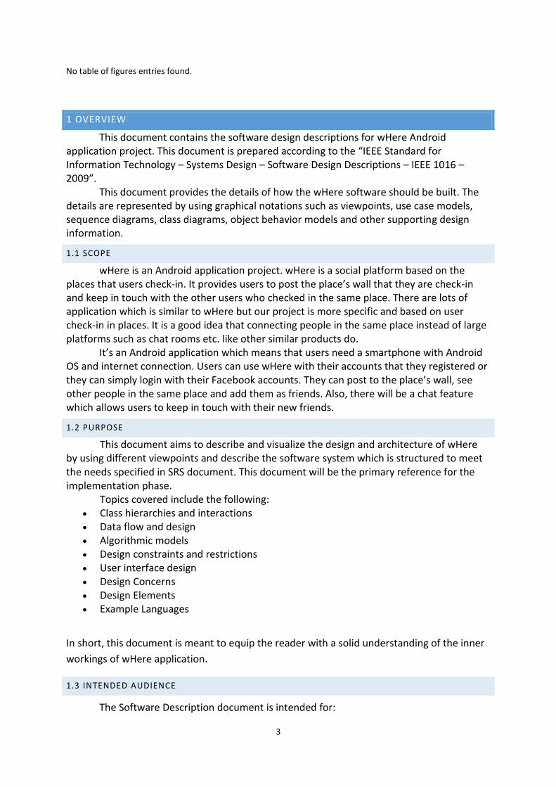
1 OVERVIEW
This document contains the software design descriptions for wHere Android application project. This document is prepared according to the “IEEE Standard for Information Technology – Systems Design – Software Design Descriptions – IEEE 1016 – 2009”. This document provides the details of how the wHere software should be built. The details are represented by using graphical notations such as viewpoints, use case models, sequence diagrams, class diagrams, object behavior models and other supporting design information.
1.1 SCOPE
wHere is an Android application project. wHere is a social platform based on the places that users check-in. It provides users to post the place’s wall that they are check-in and keep in touch with the other users who checked in the same place. There are lots of application which is similar to wHere but our project is more specific and based on user check-in in places. It is a good idea that connecting people in the same place instead of large platforms such as chat rooms etc. like other similar products do. It’s an Android application which means that users need a smartphone with Android OS and internet connection. Users can use wHere with their accounts that they registered or they can simply login with their Facebook accounts. They can post to the place’s wall, see other people in the same place and add them as friends. Also, there will be a chat feature which allows users to keep in touch with their new friends.
1.2 PURPOSE
This document aims to describe and visualize the design and architecture of wHere by using different viewpoints and describe the software system which is structured to meet the needs specified in SRS document. This document will be the primary reference for the implementation phase.
Topics covered include the following: Class hierarchies and interactions Data flow and design Algorithmic models Design constraints and restrictions User interface design Design Concerns Design Elements Example Languages
In short, this document is meant to equip the reader with a solid understanding of the inner
workings of wHere application.
1.3 INTENDED AUDIENCE
The Software Description document is intended for:
4
Developers: by using the SDD, developers can easily understand the software and it
helps developers to improve the current project features or add new features to
existing system.
Testers: by using the SDD, testers can find some bugs for their testing strategy.
Instead of searching whole software program, testers can examine SDD.
Users: by using the SDD, users can easily understand how to use the software. In this
project our users can be anyone who uses wHere application.
1.4 REFERENCES
IEEE. IEEE Std. 830-1998 IEEE Recommended Practice for Software Requirements
Specifications. IEEE Computer Society, 1998.
2 DEFINITION
Term Definition
User Someone who interacts with the application.
GPS Global Positioning System
CENG Computer engineering department of METU
Database Collection of all the information monitored by this system.
UML Diagram Unified Modeling Language (UML) is a standardized general-purpose modeling language in the field of object-oriented software engineering. The standard is managed, and was created, by the Object Management Group. UML 2.2 has 14 types of diagrams divided into two categories. Seven diagram types represent structural information, and the other seven represent general types of behavior, including four that represent different aspects of interactions.
Software
Requirements
Specification (SRS)
A complete description of the behavior of a system to be developed and may include a set of use cases that describe interactions the users will have with the software.
SDD Software Design Description which is the complete description of the design of system.
IEEE Institute of Electrical and Electronics Engineers

5
3 CONCEPTUAL MODEL FOR SOFTWARE DESIGN DESCRIPTIONS
In this section, conceptual model for the SDD will be presented. This conceptual
model mainly explains the context in which SDD is prepared.
3.1 SOFTWARE DESIGN IN CONTEXT
In wHere application, object oriented approach will be used as a design method.
Hence, it will be easier to implement the project and add possible future features.
Furthermore multi-layered system architecture will be used. Layers will help modularity,
security and adaptability of the software. With object oriented design and multi-layered
architecture, portability and integrality between components will be improved.
3.2 SOFTWARE DESIGN DESCRIPTIONS WITHIN THE LIFE CYCLE
3.2.1 INFLUENCES ON SDD PREPARATION
The key software life cycle product that drives this software design is the SRS we have
prepared. All the details and requirements are taken from there in order to prepare this
document.
3.2.2 INFLUENCES ON SOFTWARE LIFE CYCLE PRODUCTS
This SDD influences the content of SRS of this project. It also has influences on the
whole implementation phase of wHere application. More than that, the test documentation
and test plans of the system are also influenced by the SDD. In addition, the contents of SDD
is taken into consideration by the developers in order to develop test cases and test
procedures.
3.2.3 DESIGN VERIFICATION AND DESIGN ROLE IN VALIDATION
Test cases will be prepared after document phase. Verification of the software will be
tested with these test cases and all parts will be evaluated. Success of the software system
will be determined with test cases. After the results, validation of the software will be
checked if requirements of the system are fulfilled or not.
4 DESIGN DESCRIPTION INFORMATION CONTENT
4.1 INTRODUCTION
Software Design Description of the wHere gives information about how wHere will be
designed and implemented. SDD identification, design viewers, design elements, design
rationale, design languages are topics which will be described.

6
4.2. SDD IDENTIFICATION
This document is a first version of System Design Description for this project. This
SDD report prepared based on IEEE 1016-2009 standards. Draw.io is used for drawing
diagrams. Organization of the project team and date of the report are given in cover page of
SDD. In the first section an overview of SDD is given. Scope of the SDD report refers to the
section 1.1, Purpose of the SDD report refers to section 1.2 and Intended Audience of this
document refers to section 1.3. For design conceptual model for software design
descriptions refer to the section 3. Lastly, for the design viewpoints including context,
composition, logical, information, patterns use, interface, interaction, state dynamics and
resource viewpoints refer to the section 5.
4.3 DESIGN STAKEHOLDERS AND THEIR CONCERNS
In wHere, design stakeholders are the developer team of wHere and their advisors. Our design stakeholders are the people who know and understand software development and our stakeholders are the part of the development. Our stakeholders’ concerns are listed below:
The implementation should be safe, secure, maintainability and open to future
changes.
The interface shall be easy to read and use.
The desired results should be obtained from the developed system.
Server can carry whole users at the one and same time.
Database should be simple and efficient.
New features will be adapted into wHere, so software must be proper for it.
4.4 DESIGN VIEWS
Representing the diagrams of view, UML is used. Design views of this SDD are design
rational, contextual, composition, interface, logical and interaction views. These design
views are governed by design viewpoints that are explained in chapter 5.
4.5 DESIGN VIEWPOINTS
This section will be used to give brief outline on the viewpoints which are used in
chapter 5. It is defined in the IEEE 1016-2009 Standard as “The specification of the elements
and conventions available for constructing and using a design view.” There are mainly nine
design viewpoints which have been used to address the range of design concerns that have
been recognized.
7
4.5.1 CONTEXT VIEWPOINT
This view “depicts services provided by a design subject with reference to an explicit
context” (IEEE Standard). The context is defined by the elements that interact with the
software like users.
4.5.2 COMPOSITION VIEWPOINT
The Composition viewpoint describes the way the design subject is (recursively) structured into constituent parts and establishes the roles of those parts.
4.5.3 LOGICAL VIEWPOINT
This view is to elaborate existing and designed types and their implementations as
classes and interfaces with their structural static relationships. This view also uses examples
of instances of types in outlining design ideas. (IEEE Standard).
4.5.4 INFORMATION VIEWPOINT
The Information viewpoint is applicable when there is a substantial persistent data content expected with the design subject.
4.5.5 PATTERNS USE VIEWPOINT
This viewpoint addresses design ideas (emergent concepts) as collaboration patterns involving abstracted roles and connectors.
4.5.6 INTERFACE VIEWPOINT
This view provides information designers, programmers, and testers the means to
know how to correctly use the services provided by a design subject (IEEE Standard).
4.5.7 INTERACTION VIEWPOINT
The Interaction viewpoint defines strategies for interaction among entities, regarding why, where, how, and at what level actions occur.
4.5.8 STATE DYNAMICS VIEWPOINT
Reactive systems and systems whose internal behavior is of interest use this viewpoint.
4.5.9 RESOURCE VIEWPOINT
The purpose of the Resource viewpoint is to model the characteristics and utilization
of resources in a design subject.
4.6 DESIGN ELEMENTS
The main design elements are entities, attributes and some other member associated
with communication and relations between modules and user of our project. These main
design elements are defined inside the related viewpoints in detail in chapter 5.

8
4.6.1 DESIGN ENTITIES
4.6.1.1 SERVER SYSTEM
In the wHere, the CENG department’s server is used for web server. It enables people
to connect wHere.
4.6.1.2 DATABASE MANAGEMENT SYSTEM
In the wHere, MySQL 5.5 is used for database management. It stores data and it organizes data according to their kind. MySQL database is a common way to store data. It’s possible to make efficient queries. MySQL database will be used to store action of users and software.
4.6.1.3 CLIENT SYSTEM
Clients are connecting to wHere via mobile phones. Clients must use mobile phones
which has Android OS.
4.6.1.4 I/O HANDLING COMPONENT
Users make their connections all of components of wHere through I/O handling
component.
4.6.1.5 PROGRAMMING LANGUAGE
The application will be implemented in Java and it will use Android SDK, Facebook
SDK and Google Maps SDK. Eclipse will be used as IDE while implementing.
4.6.2 DESIGN RELATIONSHIPS
wHere’s main systems are MySQL Database, Java Program, Database Connection Component, I/O Handling Component, Client System, Database Management System, CENG department’s Server System.
Their relationships will be described in section 5.
4.6.3 DESIGN CONSTRAINTS
Software must be implemented object oriented and it must be reusable. System must be formed of subsystems and they should be implemented separate
and understandable. MySQL 5.5 must be used in the database management. Application server is developed in java.
Classes and their entities must be implemented according to design classes and their
entities.
4.7 DESIGN OVERLAYS
In wHere, simplicity, maintainability and durability are main factors to determine
design choices. Considering new features which are probably added the software in the
future, wHere is designed with this vision. Therefore developers of wHere document all

9
development process and they put their comments into their code, so new developers who
do not have any idea about wHere can understand the system and they can add new
features or modify old features easily in the future.
4.8 DESIGN RATIONALE
In this project, design choices are made according to performance concerns and
integrality of the system. System has to be designed in a way that future models and
features can be added and current models can be changed and updated independently.
Stakeholders may have and request further requirements, therefore system parts have to be
modular. Developers of the system has to document development process and use
comments in their code frequently, so that in the future other developers may understand
code and the structure of the system.
4.9 DESIGN LANGUAGES
In this project, Unified Modeling Language (UML) is selected as a part of design
viewpoint and it will be used for clarifying design viewpoints.
5 DESIGN VIEWPOINTS
5.1 INTRODUCTION
In this chapter, the viewpoints of the wHere is explained in detail. During this section,
UML diagrams will be used to increase understandability. This section will explain thirteen
main design viewpoint in detail.
Context viewpoint Composition viewpoint Logical viewpoint Dependency viewpoint Information viewpoint Patterns use viewpoint Interface viewpoint Structure viewpoint Interaction viewpoint State dynamics viewpoint Algorithm viewpoint Resource viewpoint
5.2 CONTEXT VIEWPOINTS
5.2.1 DESIGN CONCERNS
10
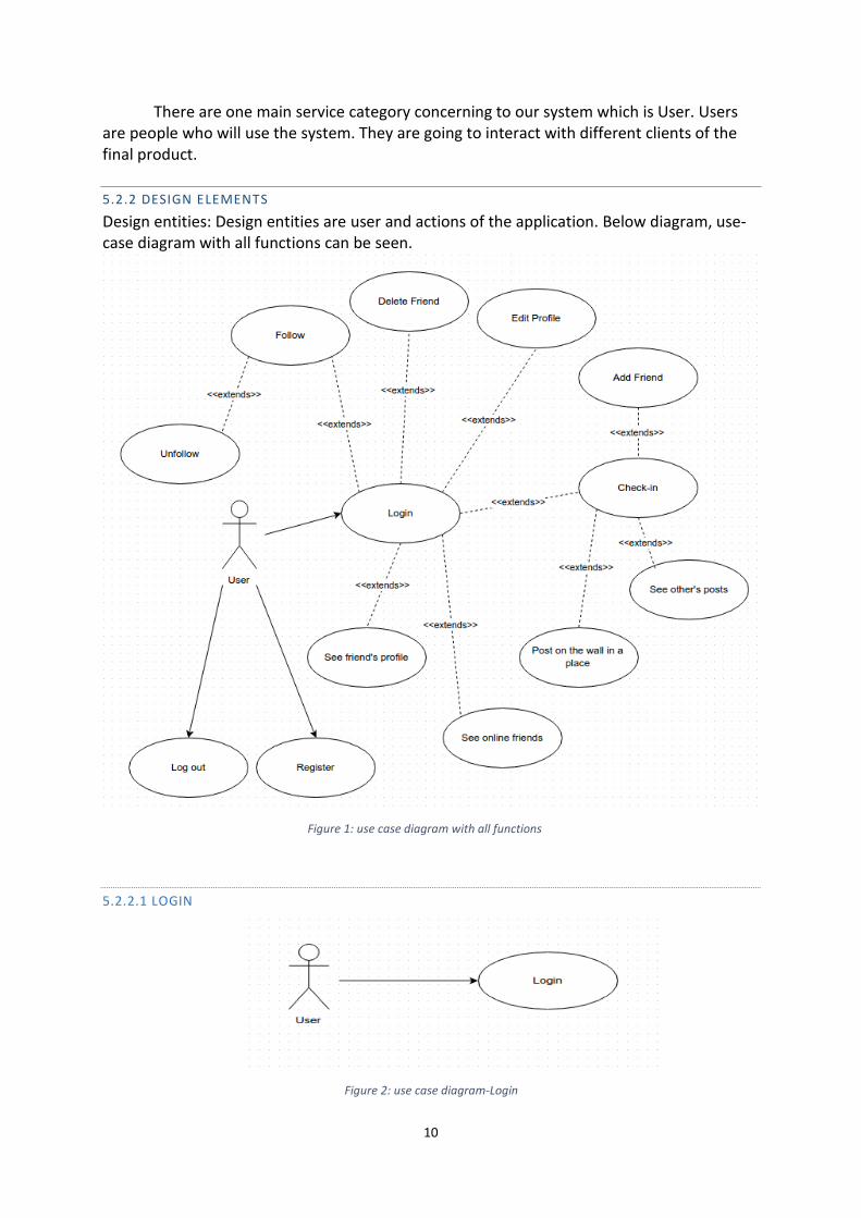
There are one main service category concerning to our system which is User. Users are people who will use the system. They are going to interact with different clients of the final product.
5.2.2 DESIGN ELEMENTS
Design entities: Design entities are user and actions of the application. Below diagram, use-case diagram with all functions can be seen.
Figure 1: use case diagram with all functions
5.2.2.1 LOGIN
Figure 2: use case diagram-Login
11
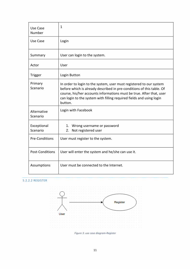
Use Case Number
1
Use Case Login
Summary User can login to the system.
Actor User
Trigger Login Button
Primary Scenario
In order to login to the system, user must registered to our system before which is already described in pre-conditions of this table. Of course, his/her accounts informations must be true. After that, user can login to the system with filling required fields and using login button.
Alternative Scenario
Login with Facebook
Exceptional Scenario
1. Wrong username or password 2. Not registered user
Pre-Conditions User must register to the system.
Post-Conditions User will enter the system and he/she can use it.
Assumptions User must be connected to the Internet.
5.2.2.2 REGISTER
Figure 3: use case diagram-Register
12
Use Case Number
2
Use Case Register
Summary User needs to register to use the product.
Actor User
Trigger Register Button
Primary Scenario
After user download the “wHere”, he/she must register the system in order to use the product. In the login page there will be register button. This button redirects user to the register page. After filling required fields with information, he/she can register to the system with using register button.
Alternative Scenario A user can also register to “wHere” with using his/her Facebook account.
In this scenario, user can register system without typing any information.
Exceptional Scenario
1. User name has already taken. 2. Password does not match.
Pre- Conditions
Having e-mail or having a Facebook account.
Post- Conditions
After registering to system, user can start to use the product.
Assumptions Having valid e-mail address.
5.2.2.3 LOGOUT
Figure 4: use case diagram-Log out
13
Use Case Number 3
Use Case Log out
Summary User can log out from the system
Actor User
Trigger Log out Button
Primary Scenario After login, user can log out at any time.
Alternative Scenario None
Exceptional Scenario None
Pre-Conditions Login
Post-Conditions User will be redirected to the login page.
Assumptions User has already logged in to the system.
5.2.2.4 FOLLOW
Figure 5: use case diagram-Follow
Use Case Number
4
Use Case Follow
14
Summary User can follow any of his/her friends to see their post that are posted in any place.
Actor User
Trigger Follow Button
Primary Scenario
If user wants to see what his/her friends share in places, user can send follow request to any of the friends. According to request response user can follow the friend.
Alternative Scenario
None
Exceptional Scenario
None
Pre-Conditions Users can follow only their friends
Post-Conditions Any post that is shared by friends who is followed by the user can be seen in user’s main page.
Assumptions None
5.2.2.5 UNFOLLOW
Figure 6: use case diagram-Unfollow
Use Case Number
5
Use Case Unfollow
15
Summary User can give up following friends
Actor User
Trigger Unfollow Button
Primary Scenario After pressing unfollow button for a friend, user give up following him/her. User also can also delete any of his/her followers.
Alternative Scenario
None
Exceptional Scenario
None
Pre-Conditions Following is obligatory to unfollow friend
Post-Conditions After unfollowing friend, user will not get any post from this friend.
Assumptions Before unfollowing a friend he/she must already be followed.
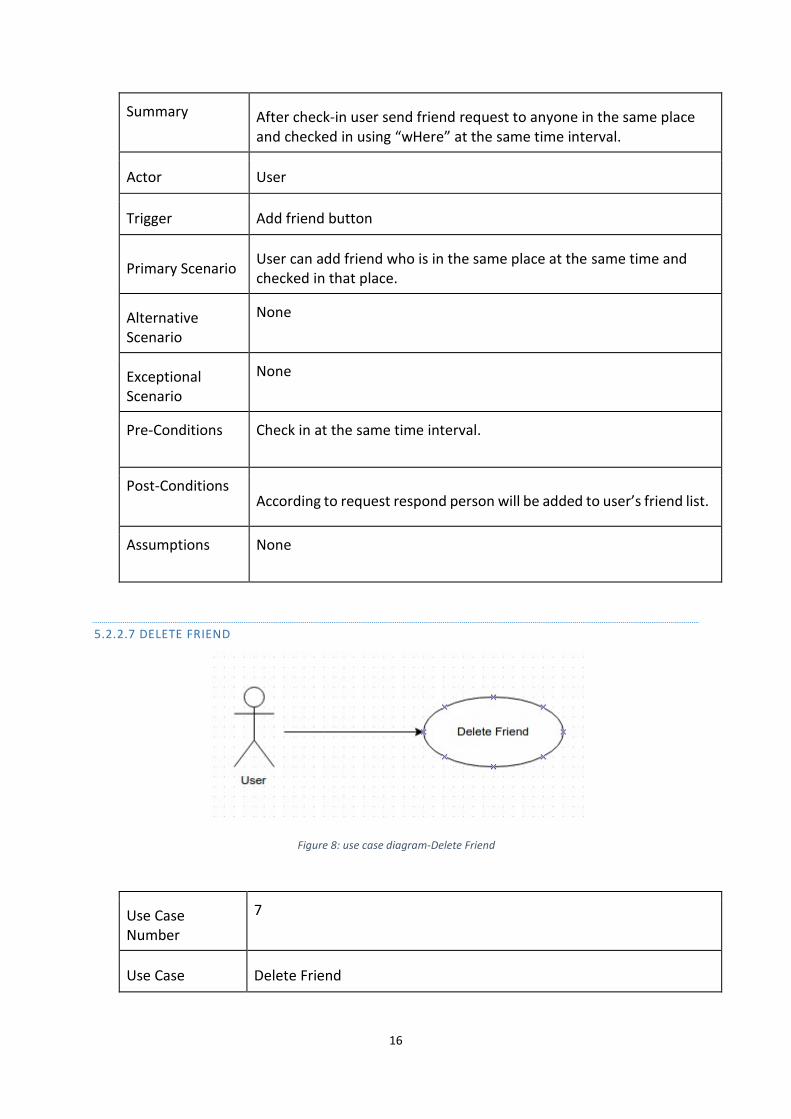
5.2.2.6 ADD FRIEND
Figure 7: use case diagram-Add Friend
Use Case Number
6
Use Case Add Friend
16
Summary After check-in user send friend request to anyone in the same place and checked in using “wHere” at the same time interval.
Actor User
Trigger Add friend button
Primary Scenario User can add friend who is in the same place at the same time and checked in that place.
Alternative Scenario
None
Exceptional Scenario
None
Pre-Conditions Check in at the same time interval.
Post-Conditions According to request respond person will be added to user’s friend list.
Assumptions None
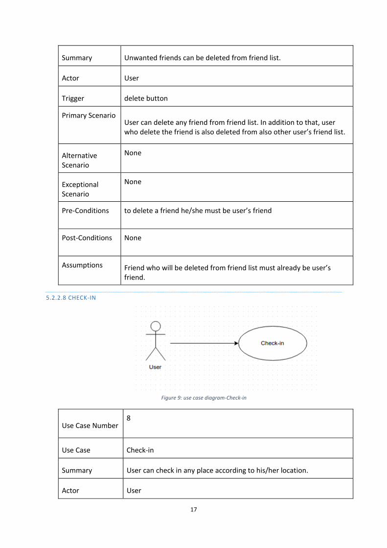
5.2.2.7 DELETE FRIEND
Figure 8: use case diagram-Delete Friend
Use Case Number
7
Use Case Delete Friend
17
Summary Unwanted friends can be deleted from friend list.
Actor User
Trigger delete button
Primary Scenario User can delete any friend from friend list. In addition to that, user who delete the friend is also deleted from also other user’s friend list.
Alternative Scenario
None
Exceptional Scenario
None
Pre-Conditions to delete a friend he/she must be user’s friend
Post-Conditions None
Assumptions Friend who will be deleted from friend list must already be user’s friend.
5.2.2.8 CHECK-IN
Figure 9: use case diagram-Check-in
Use Case Number 8
Use Case Check-in
Summary User can check in any place according to his/her location.
Actor User
18
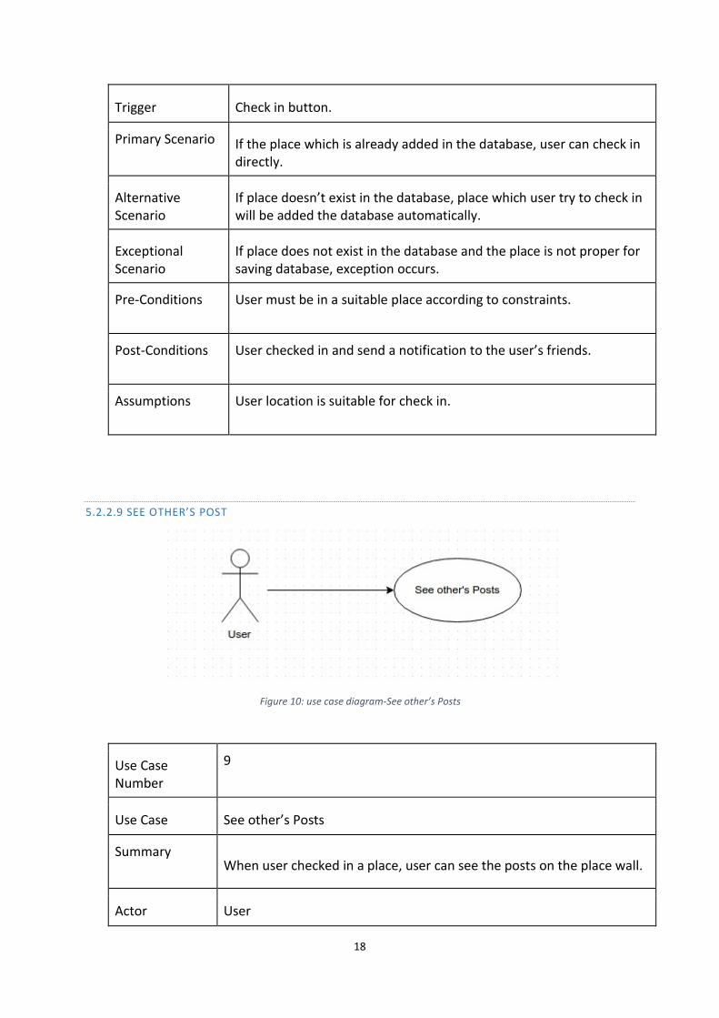
Trigger Check in button.
Primary Scenario If the place which is already added in the database, user can check in directly.
Alternative Scenario
If place doesn’t exist in the database, place which user try to check in will be added the database automatically.
Exceptional Scenario
If place does not exist in the database and the place is not proper for saving database, exception occurs.
Pre-Conditions User must be in a suitable place according to constraints.
Post-Conditions User checked in and send a notification to the user’s friends.
Assumptions User location is suitable for check in.
5.2.2.9 SEE OTHER’S POST
Figure 10: use case diagram-See other’s Posts
Use Case Number
9
Use Case See other’s Posts
Summary When user checked in a place, user can see the posts on the place wall.
Actor User

19
Trigger After check in, the wall which belongs to the place is opened automatically.
Primary Scenario
User can see posts which have posted before in a place which user have already checked in and still there. If user checked in and time out he/she cannot see the posts on the place wall.
Alternative Scenario
None
Exceptional Scenario
None
Pre-Conditions Check in is required.
Post- Conditions
None
Assumptions None
5.2.2.10 POST ON THE WALL IN A PLACE
Figure 11: use case diagram-Post on the wall in a place
Use Case Number
10
Use Case Post on the wall in a place
Summary This use case deals with posting on the wall of the place where user checked in.
Actor User
20
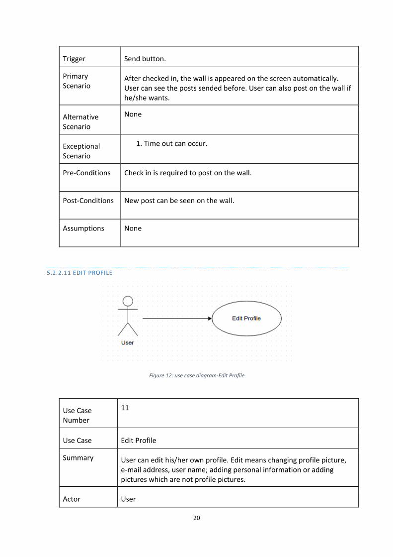
Trigger Send button.
Primary Scenario
After checked in, the wall is appeared on the screen automatically. User can see the posts sended before. User can also post on the wall if he/she wants.
Alternative Scenario
None
Exceptional Scenario
1. Time out can occur.
Pre-Conditions Check in is required to post on the wall.
Post-Conditions New post can be seen on the wall.
Assumptions None
5.2.2.11 EDIT PROFILE
Figure 12: use case diagram-Edit Profile
Use Case Number
11
Use Case Edit Profile
Summary User can edit his/her own profile. Edit means changing profile picture, e-mail address, user name; adding personal information or adding pictures which are not profile pictures.
Actor User
21
Trigger Edit button on the user profile page.
Primary Scenario
From user profile after touching Edit Profile button user will be redirected to Profile Edit page which includes all user informations. After editing those informations, user can update the changes by touching Apply button.
Alternative Scenario
After editing some information, user can cancel the changes by clicking cancel button.
Exceptional Scenario
None
Pre-Conditions Login is required.
Post- Conditions
Profile will be updated.
Assumptions None
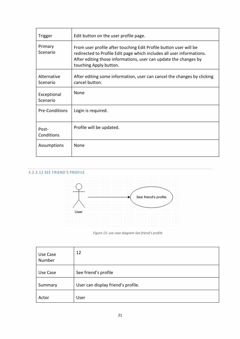
5.2.2.12 SEE FRIEND’S PROFILE
Figure 13: use case diagram-See friend’s profile
Use Case Number
12
Use Case See friend’s profile
Summary User can display friend’s profile.
Actor User
22
Trigger By touching friend’s profile picture.
Primary Scenario
In the friend list, after touching friend’s profile picture user will be redirected to friend’s profile.
Alternative Scenario
In the main page, there will be notifications about friend’s activities. User can touch user name of any friend’s and be redirected to friend’s profile page.
Exceptional Scenario
None
Pre-Conditions None
Post-Conditions Redirected to friend’s profile page.
Assumptions None
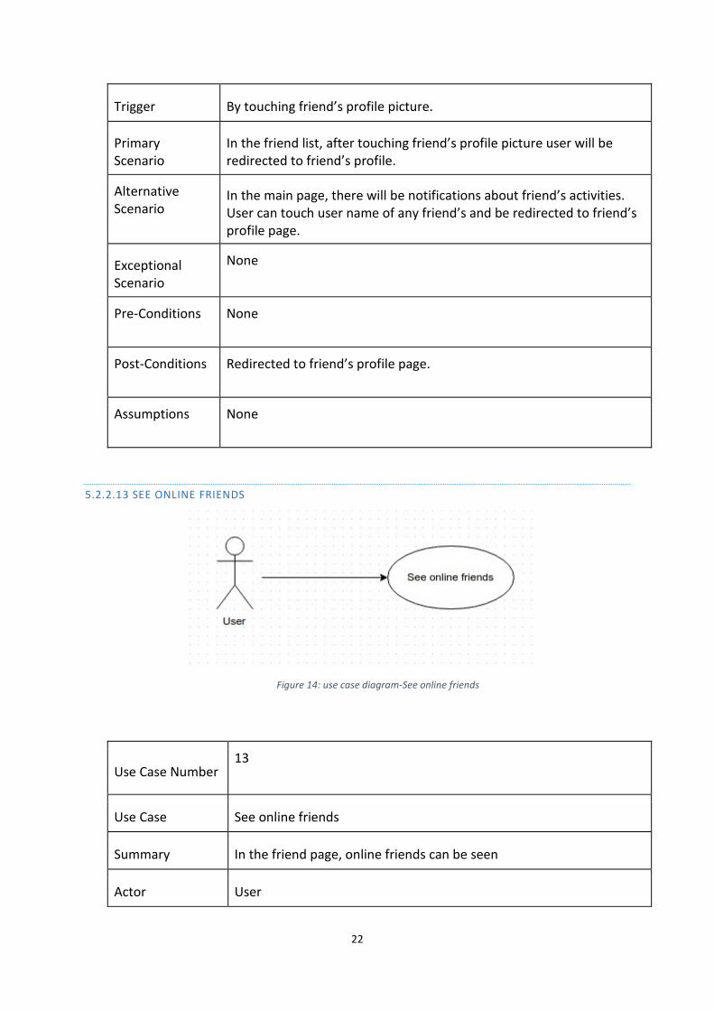
5.2.2.13 SEE ONLINE FRIENDS
Figure 14: use case diagram-See online friends
Use Case Number 13
Use Case See online friends
Summary In the friend page, online friends can be seen
Actor User
23
Trigger In the profile page, touching the friends button.
Primary Scenario After touching friends button, user will be redirected to friends page. Online friend list can be seen on this page.
Alternative Scenario
None
Exceptional Scenario
None
Pre-Conditions None
Post-Conditions None
Assumptions None
5.3 COMPOSITION VIEWPOINT
5.3.1 DESIGN CONCERNS
Composition viewpoint will help to manage software process. In this part, main work components and components inside those will be identified. There will be tree main work components in this software. Namely: Database server, web server and client.
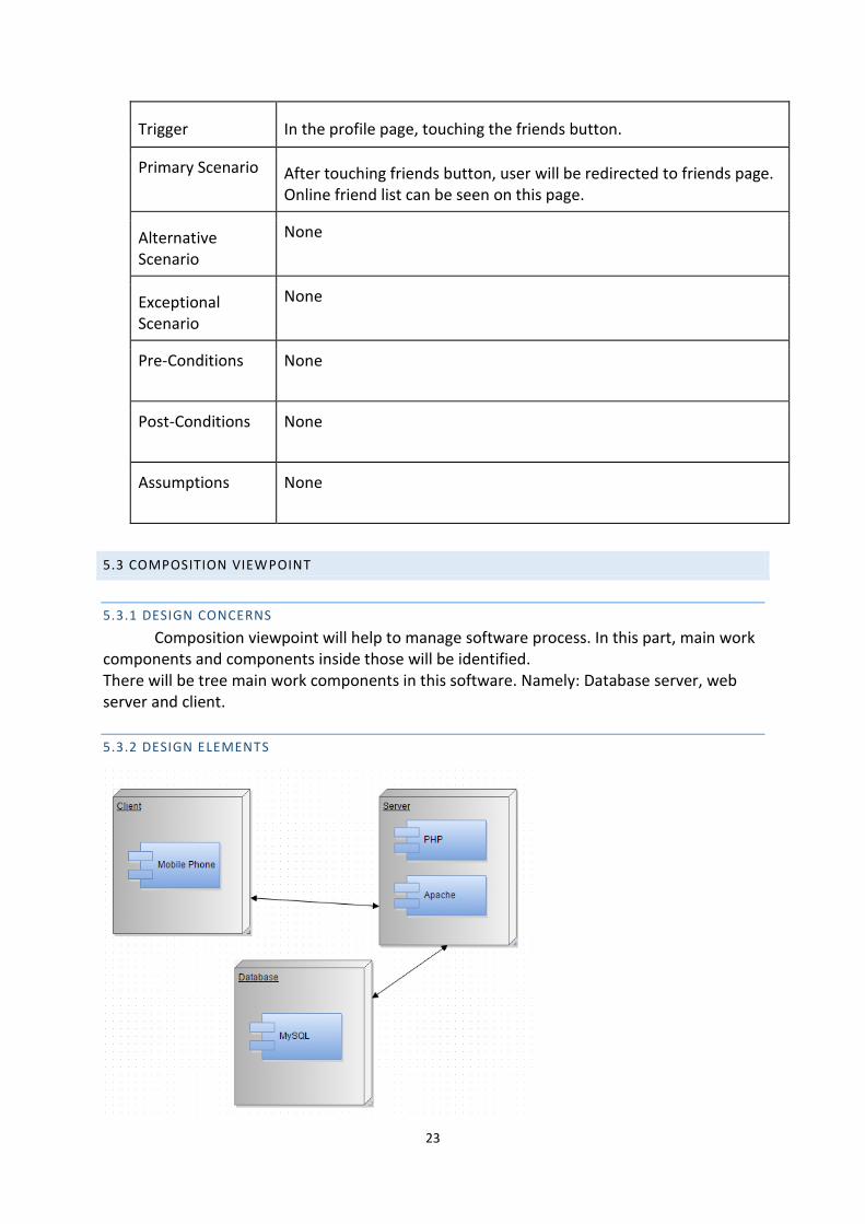
5.3.2 DESIGN ELEMENTS
24
Figure 15: Deployment diagram
Design Entities: There are three main design components in our project which are
namely client, database and server.
Server establishes connection between the client and the database.
Design Attributes: Design attributes are discussed in the following two chapters.
Database is placed at lower level of system
5.3.2.1 FUNCTION ATTRIBUTE
Database, server and client are the main components of wHere project. Server is
responsible for providing an interaction between client and the database. The database will
store information.
5.3.2.2 SUBORDINATES ATTRIBUTE
All of the components mentioned in the previous subsection are composed together
in order to construct wHere application.
5.4 LOGICAL VIEWPOINT
5.4.1 DESIGN CONCERNS
Logical viewpoint will identify all classes and relations between classes in wHere. Aim
of logical viewpoint is to clarify and simplify the system design and lead development team.
Firstly, a complete class diagram containing all classes and their relations are given. Then,
each of the classes and their methods and fields are explained in detail.
5.4.2 DESIGN ELEMENTS
5.4.2.1 CLASS RELATIONS
The class diagram below shows the class relations in wHere. There are four classes
related each other, namely user, post, place, chat. Below class diagram shows only the main
classes. There are also trivial classes which are not shown to make easier to understand class
relationships.

25
Figure 16: Class diagram
5.4.2.2 USER CLASS
User class’s fields and methods are shown below.
Method/Field Definition String name The name of user. String surname The surname of the user. String username The username of the user. String password The password of the user. String e-mail The email of the user. String profile_pic date dateOfBirth String hometown String education String gender String job String phone String relationship int user_id
Profile picture URL of the user. Birth day of the user. Hometown of the user. Education of the user. Gender of the user. Job of the user. Phone number of the user. Relationship of the user. User id of the user.
26
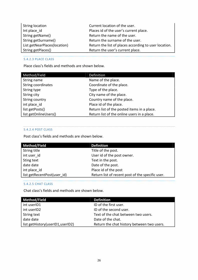
String location Int place_id String getName() String getSurname() List getNearPlaces(location) String getPlaces()
Current location of the user. Places id of the user’s current place. Return the name of the user. Return the surname of the user. Return the list of places according to user location. Return the user’s current place.
5.4.2.3 PLACE CLASS
Place class’s fields and methods are shown below.
Method/Field Definition String name Name of the place. String coordinates Coordinate of the place. String type Type of the place. String city City name of the place. String country Country name of the place. int place_id list getPosts() list getOnlineUsers()
Place id of the place. Return list of the posted items in a place. Return list of the online users in a place.
5.4.2.4 POST CLASS
Post class’s fields and methods are shown below.
Method/Field Definition String title Title of the post. int user_id Sting text date date int place_id list getRecentPost(user_id)
User id of the post owner. Text in the post. Date of the post. Place id of the post Return list of recent post of the specific user.
5.4.2.5 CHAT CLASS
Chat class’s fields and methods are shown below.
Method/Field Definition int userID1 ID of the first user. int userID2 String text date date list getHistory(userID1,userID2)
ID of the second user. Text of the chat between two users. Date of the chat. Return the chat history between two users.
27
5.5 DEPENDENCY VIEWPOINT
The dependency viewpoint specifies the relationships and dependencies between the
design components of the system.
5.5.1 DESIGN CONCERNS
Identifying the dependencies of the application wHere and determining which
subsystems are depends on other subsystems helps deciding the priorities in developing
design entities.
5.5.2 DESIGN ELEMENTS
Design Entities: Server (Apache), database server (MySQL) and the client.
Design Relationships: Each entities are related each other. Database Server is placed
at lower level of system. Server is between the client and database.
5.5.3 EXAMPLE LANGUAGES
Deployment diagram of the system is supplied in section 5.3.2. You can refer to that
subsection for the diagram, see figure 15.
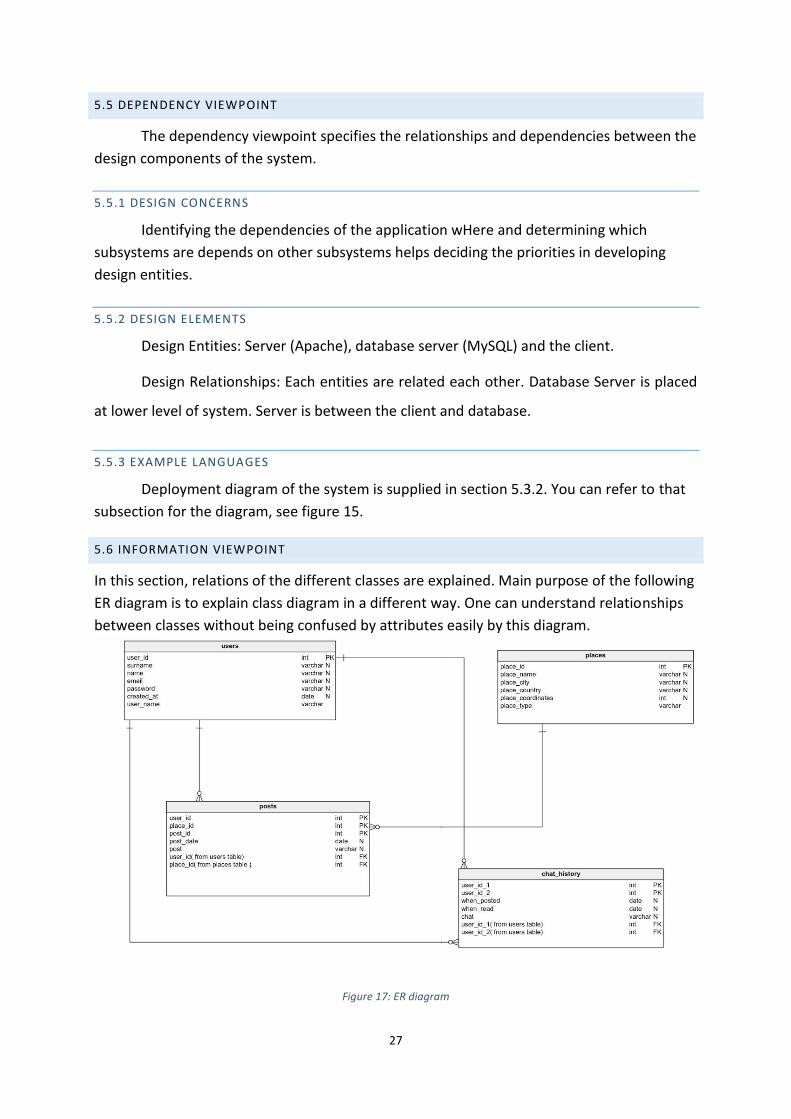
5.6 INFORMATION VIEWPOINT
In this section, relations of the different classes are explained. Main purpose of the following
ER diagram is to explain class diagram in a different way. One can understand relationships
between classes without being confused by attributes easily by this diagram.
Figure 17: ER diagram
28
5.7 PATTERNS USE VIEWPOINT
Design patterns are elements of reusable object oriented software. In order to make
some parts of the software reusable, some design patterns are used. In our project we will
use server-client design pattern. These patterns are not only reusable but also applicable to
any data. Usage of the pattern is explained below.
5.7.1 DESIGN CONCERN
wHere will be implemented by using server-client pattern. The client–server model of
computing is a distributed application structure that partitions tasks or workloads between
the providers of a resource or service, called servers, and service requesters, called clients. In
our application, clients and servers communicate over an internet network on separate
hardware namely Android phones and a server. Server host runs server programs which
share their resources with clients. A client does not share any of its resources, but requests a
server's content or service function. Clients therefore initiate communication sessions with
servers which await incoming requests.
5.8 INTERFACE VIEWPOINT
5.8.1 DESIGN CONCERNS
The interface viewpoint provides information for designers, programmers, testers
and costumers to acquire knowledge about how to use CENG News Collector correctly. In
every subsection, related interfaces will be described in details.
5.8.2 DESIGN ELEMENTS
5.8.2.1 WELCOME PAGE
After downloading wHere, and running the application first time, user will be directed
to Welcome page. After clicking Let’s Start button, user will be redirected to login page.
29
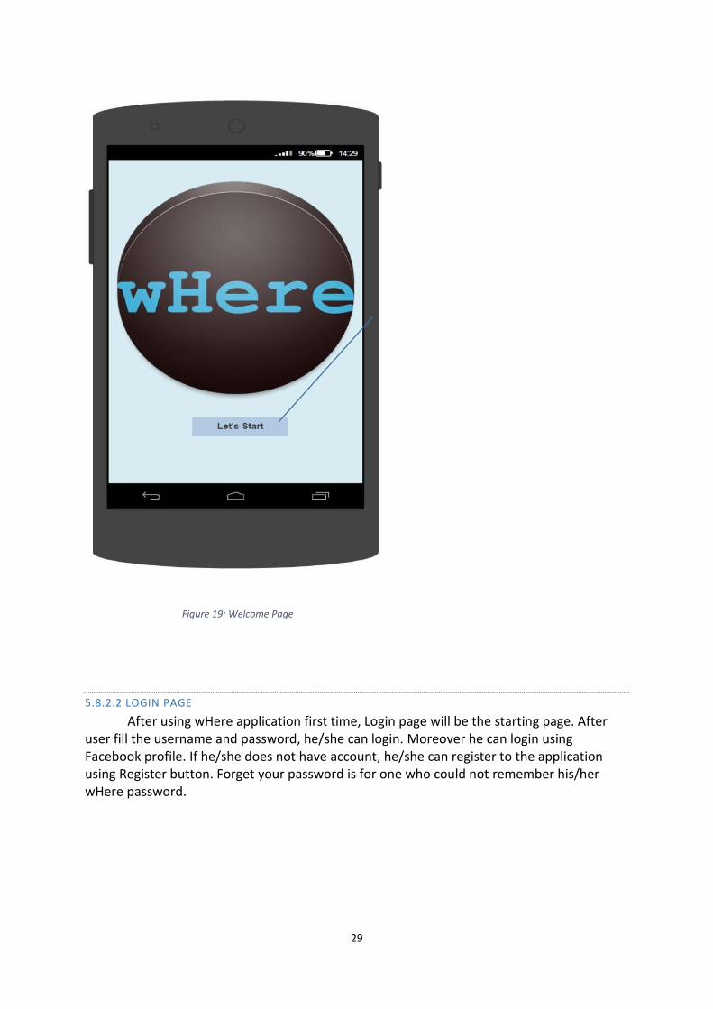
Figure 19: Welcome Page
5.8.2.2 LOGIN PAGE
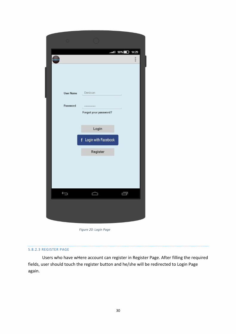
After using wHere application first time, Login page will be the starting page. After user fill the username and password, he/she can login. Moreover he can login using Facebook profile. If he/she does not have account, he/she can register to the application using Register button. Forget your password is for one who could not remember his/her wHere password.
30
Figure 20: Login Page
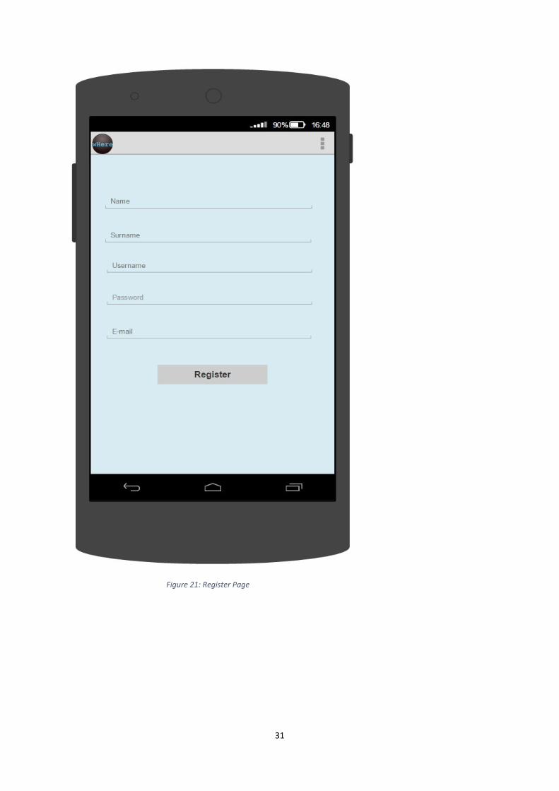
5.8.2.3 REGISTER PAGE
Users who have wHere account can register in Register Page. After filling the required
fields, user should touch the register button and he/she will be redirected to Login Page
again.
31
Figure 21: Register Page
32
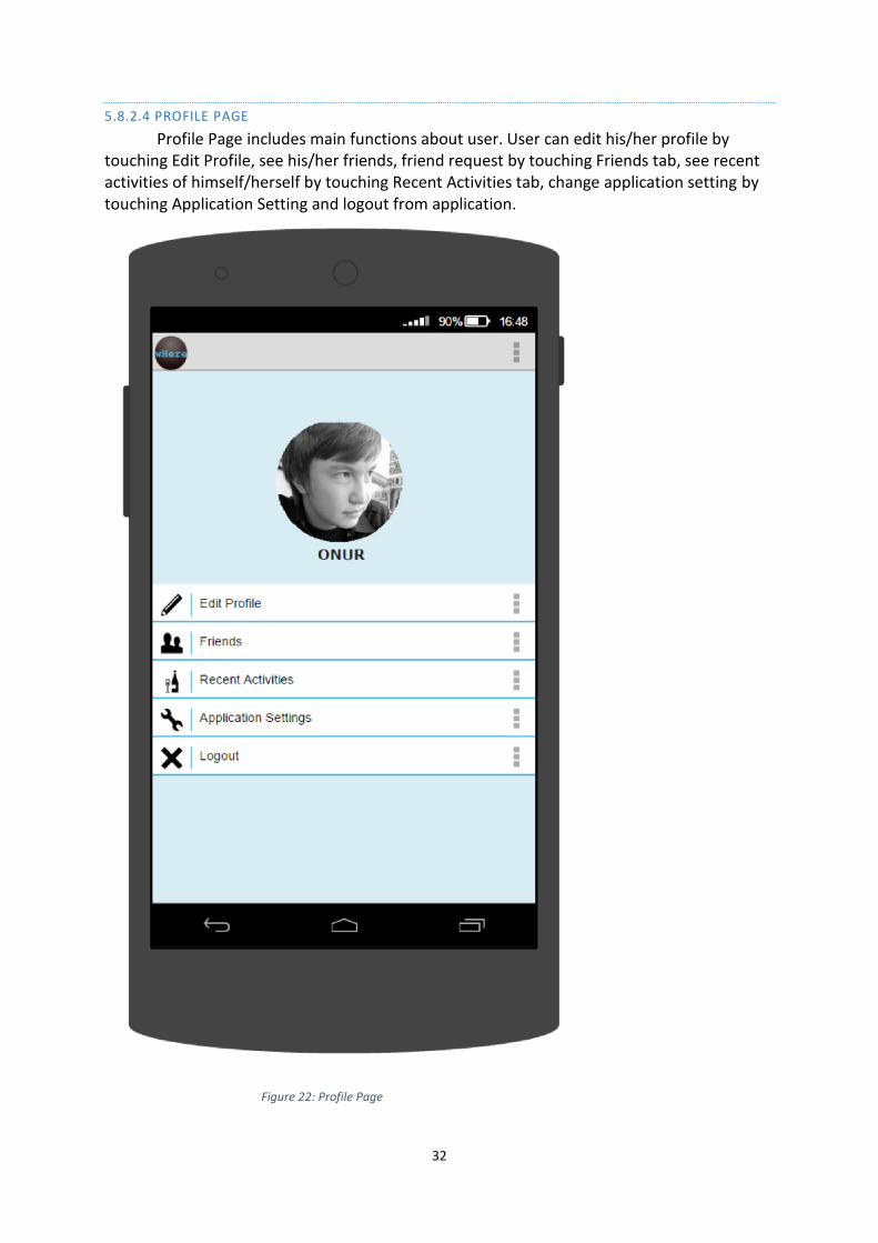
5.8.2.4 PROFILE PAGE
Profile Page includes main functions about user. User can edit his/her profile by touching Edit Profile, see his/her friends, friend request by touching Friends tab, see recent activities of himself/herself by touching Recent Activities tab, change application setting by touching Application Setting and logout from application.
Figure 22: Profile Page
33
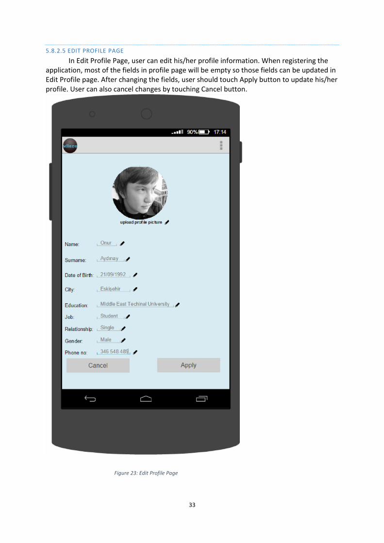
5.8.2.5 EDIT PROFILE PAGE
In Edit Profile Page, user can edit his/her profile information. When registering the application, most of the fields in profile page will be empty so those fields can be updated in Edit Profile page. After changing the fields, user should touch Apply button to update his/her profile. User can also cancel changes by touching Cancel button.
Figure 23: Edit Profile Page
34
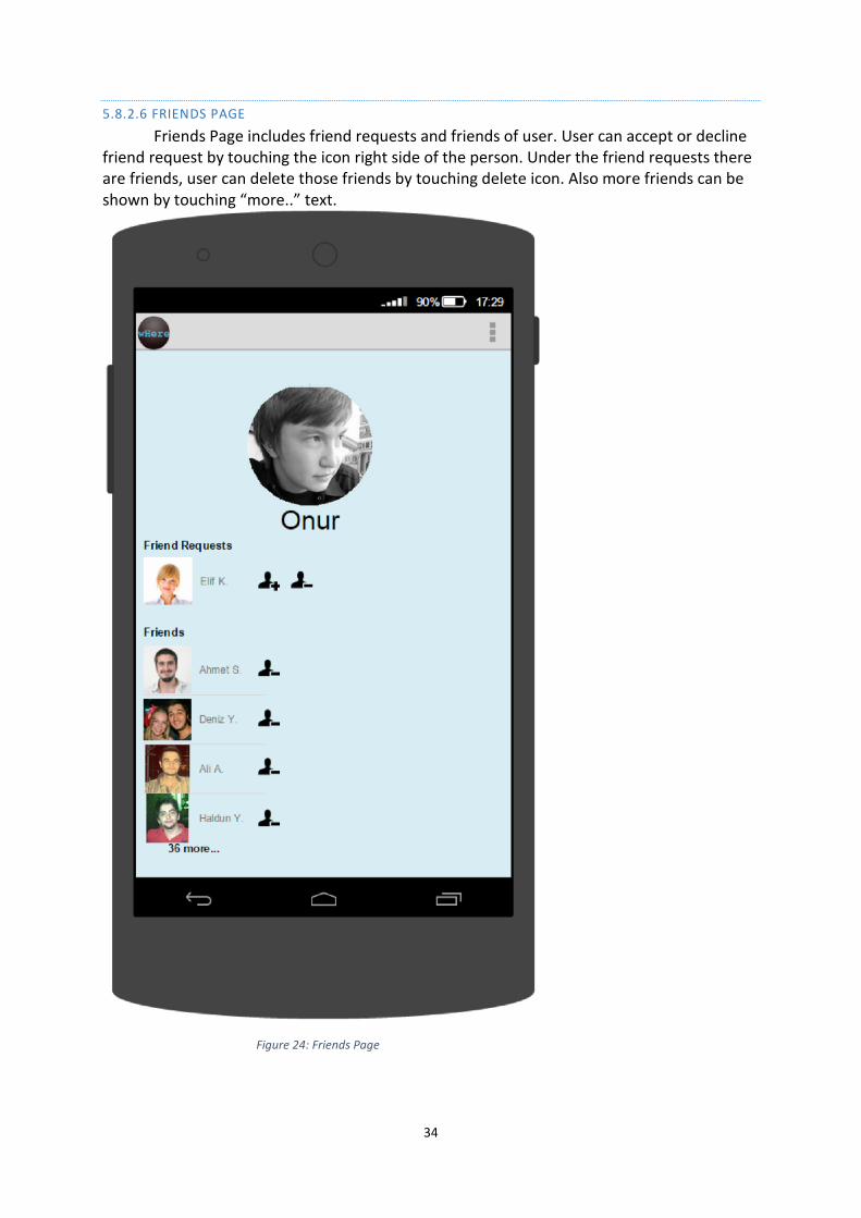
5.8.2.6 FRIENDS PAGE
Friends Page includes friend requests and friends of user. User can accept or decline friend request by touching the icon right side of the person. Under the friend requests there are friends, user can delete those friends by touching delete icon. Also more friends can be shown by touching “more..” text.
Figure 24: Friends Page
35
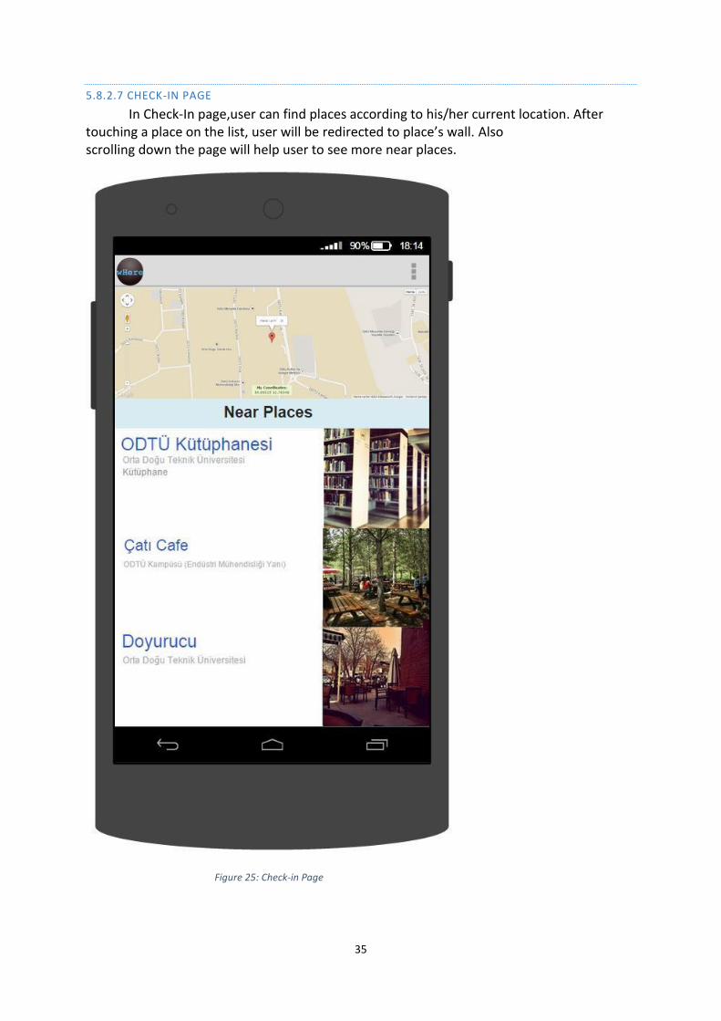
5.8.2.7 CHECK-IN PAGE
In Check-In page,user can find places according to his/her current location. After touching a place on the list, user will be redirected to place’s wall. Also scrolling down the page will help user to see more near places.
Figure 25: Check-in Page
36
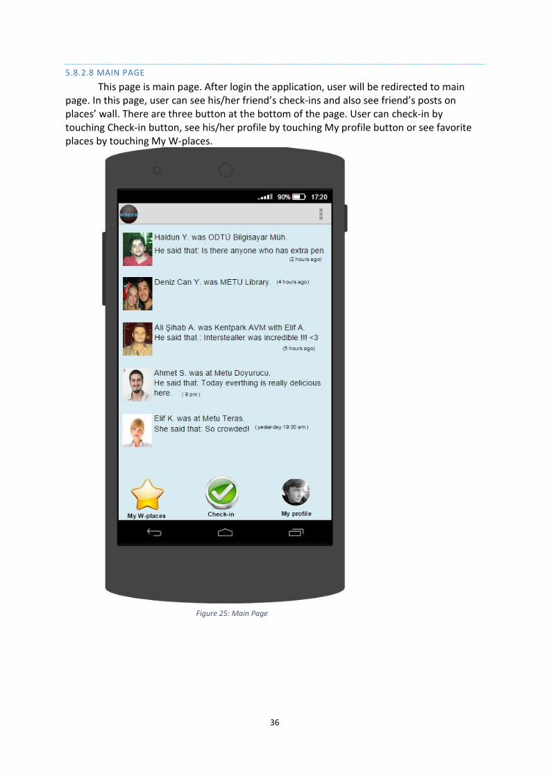
5.8.2.8 MAIN PAGE
This page is main page. After login the application, user will be redirected to main page. In this page, user can see his/her friend’s check-ins and also see friend’s posts on places’ wall. There are three button at the bottom of the page. User can check-in by touching Check-in button, see his/her profile by touching My profile button or see favorite places by touching My W-places.
Figure 25: Main Page
37
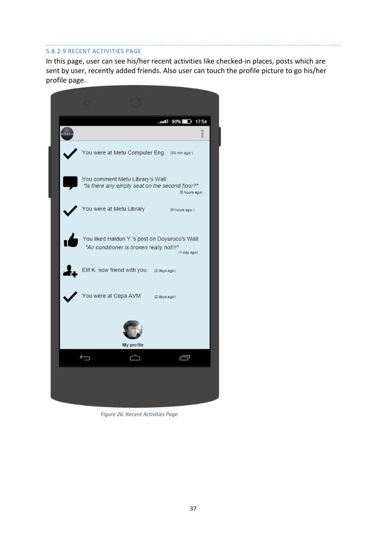
5.8.2.9 RECENT ACTIVITIES PAGE
In this page, user can see his/her recent activities like checked-in places, posts which are sent by user, recently added friends. Also user can touch the profile picture to go his/her profile page.
Figure 26: Recent Activities Page
38
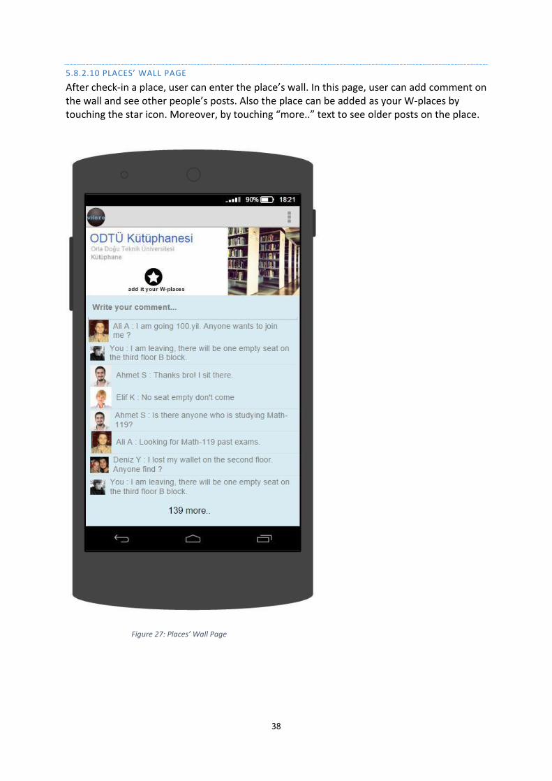
5.8.2.10 PLACES’ WALL PAGE
After check-in a place, user can enter the place’s wall. In this page, user can add comment on the wall and see other people’s posts. Also the place can be added as your W-places by touching the star icon. Moreover, by touching “more..” text to see older posts on the place.
Figure 27: Places’ Wall Page

39
5.8.2.11 OTHER USER’S PROFİLE PAGE
When user touches a profile picture who is not his/her friend, user will be redirected to his/her profile. In this page, user can add him/her as touching add icon on the bottom.
Figure 28: User’s Profile Page
40
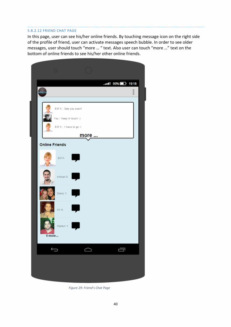
5.8.2.12 FRIEND CHAT PAGE
In this page, user can see his/her online friends. By touching message icon on the right side of the profile of friend, user can activate messages speech bubble. In order to see older messages, user should touch “more … “ text. Also user can touch “more …” text on the bottom of online friends to see his/her other online friends.
Figure 29: Friend’s Chat Page
41
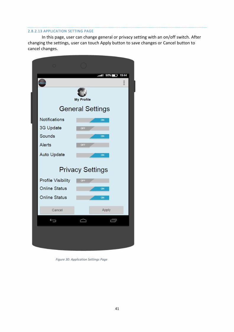
2.8.2.13 APPLICATION SETTING PAGE
In this page, user can change general or privacy setting with an on/off switch. After changing the settings, user can touch Apply button to save changes or Cancel button to cancel changes.
Figure 30: Application Settings Page
42
5.9 INTERACTION VIEWPOINT
5.9.1 DESIGN CONCERNS
The main concerns of the interaction viewpoint and this viewpoint is important when
designing and adopting patterns. Sequence Diagram is going to be used to show interaction
between objects. Since flow of event is shown sequentially in the diagram, order of the
events, satisfied and unsatisfied conditions can easily be understood. In this viewpoint we
explained the relations of modules and functions to each other and the flow of events. This
viewpoint clarifies the communication and messaging between user and modules. The flow
of events is shown sequentially which makes understanding the occasion times of events
easy. We separate this viewpoint according to modules and every module includes sequence
diagrams showing its functions and fields which provide communication between user and
other modules.
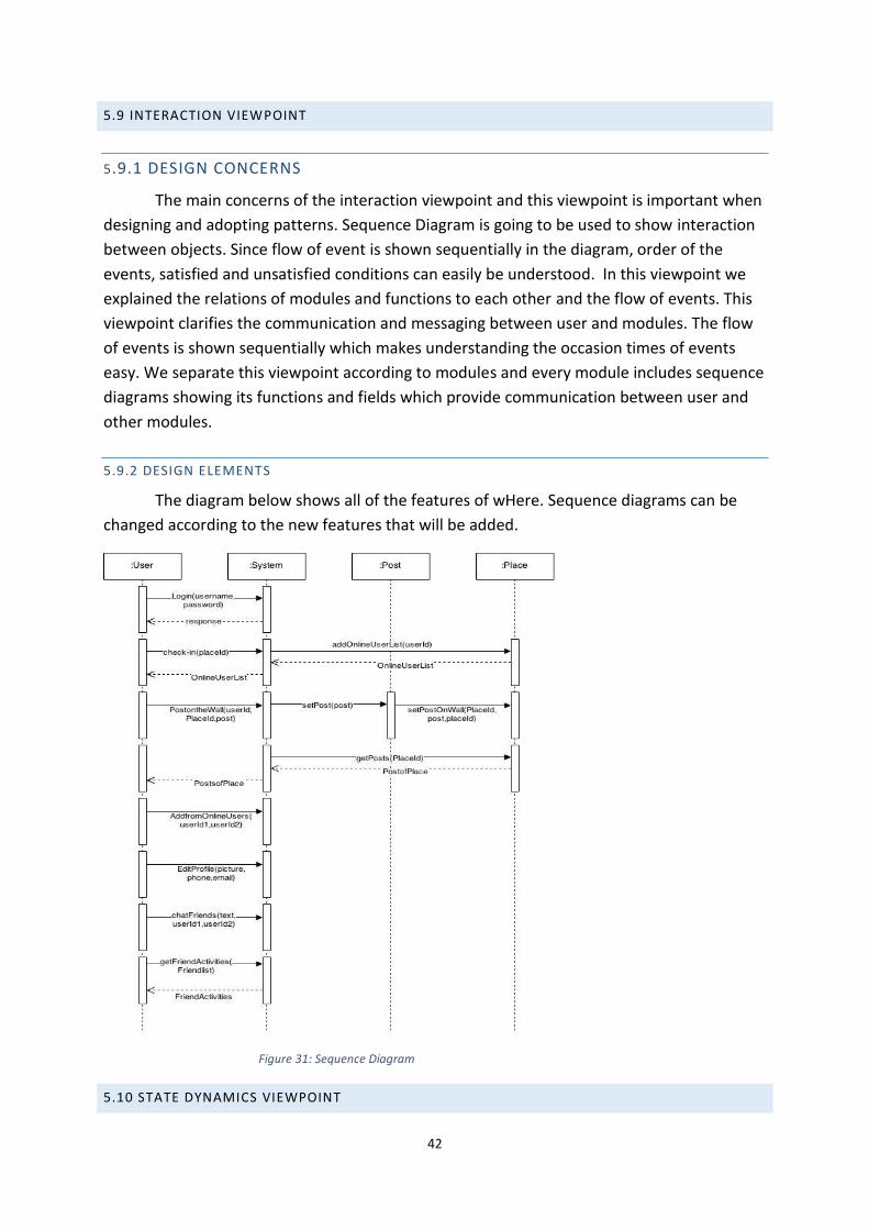
5.9.2 DESIGN ELEMENTS
The diagram below shows all of the features of wHere. Sequence diagrams can be
changed according to the new features that will be added.
Figure 31: Sequence Diagram
5.10 STATE DYNAMICS VIEWPOINT
43
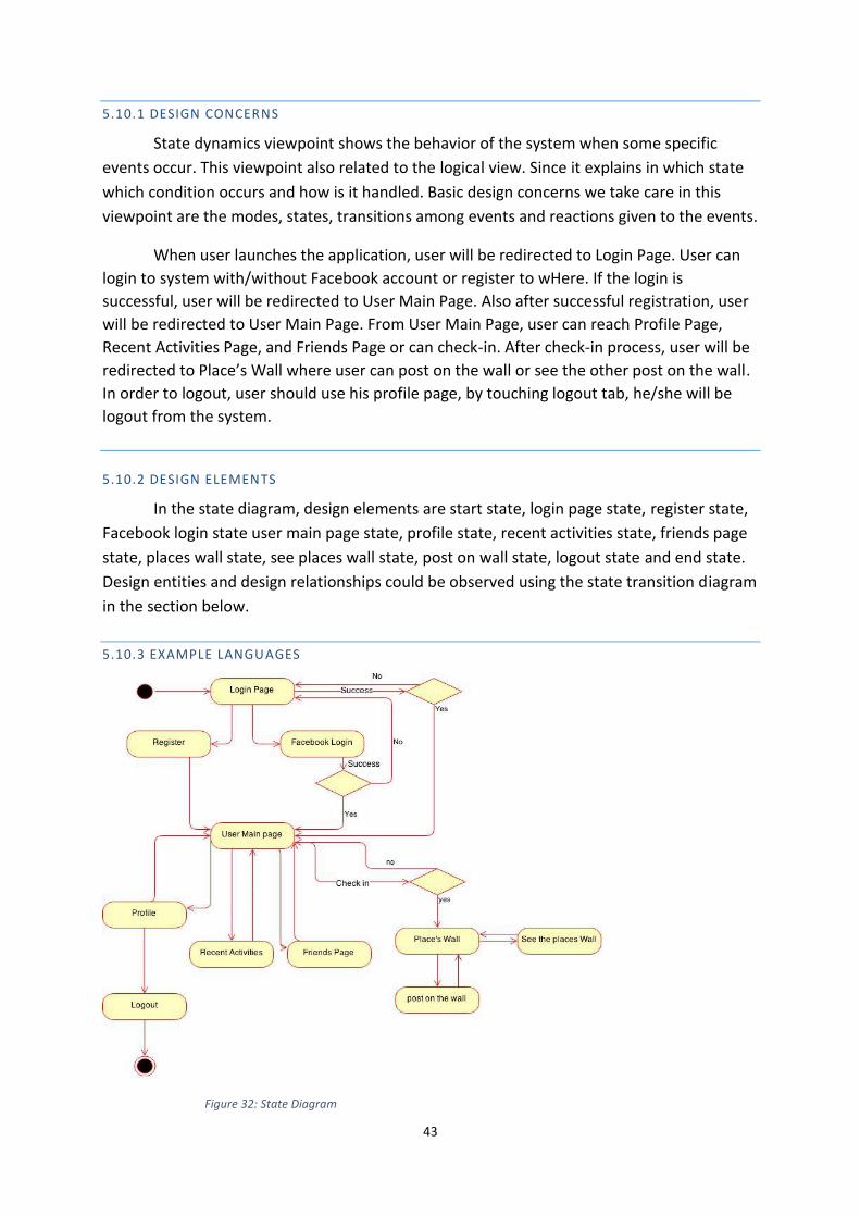
5.10.1 DESIGN CONCERNS
State dynamics viewpoint shows the behavior of the system when some specific
events occur. This viewpoint also related to the logical view. Since it explains in which state
which condition occurs and how is it handled. Basic design concerns we take care in this
viewpoint are the modes, states, transitions among events and reactions given to the events.
When user launches the application, user will be redirected to Login Page. User can
login to system with/without Facebook account or register to wHere. If the login is
successful, user will be redirected to User Main Page. Also after successful registration, user
will be redirected to User Main Page. From User Main Page, user can reach Profile Page,
Recent Activities Page, and Friends Page or can check-in. After check-in process, user will be
redirected to Place’s Wall where user can post on the wall or see the other post on the wall.
In order to logout, user should use his profile page, by touching logout tab, he/she will be
logout from the system.
5.10.2 DESIGN ELEMENTS
In the state diagram, design elements are start state, login page state, register state,
Facebook login state user main page state, profile state, recent activities state, friends page
state, places wall state, see places wall state, post on wall state, logout state and end state.
Design entities and design relationships could be observed using the state transition diagram
in the section below.
5.10.3 EXAMPLE LANGUAGES
Figure 32: State Diagram
44
5.11 ALGORITHM VIEWPOINT
Algorithm viewpoint is not available.
5.12 RESOURCE VIEWPOINT
Resource viewpoint is not available.