softswitch128 technical guide - lutron electronics company
TRANSCRIPT

Softswitch128™ technical guide

Lutron World Headquarters,Coopersburg, Pennsylvania
Innovation and quality from the world leader in lighting controls.
In 1961, Lutron introduced the world’s first electronic (solid-state) dimmer. From that point forward, Lutron innovations transformed the world of lighting controls.Today, with more than 75 utility and 180 design patents,and more than 10,000 products shipped to 80 countriesworldwide, Lutron continues to lead the way with innovation and quality.
seeTouch™ wallstations from Lutron – the new standard for ease of use and intuitive control.
www.lutron.com/switchingsystems
Lutron® Softswitch128™ technical guide

www.lutron.com/switchingsystems i
Commitment to innovation
World-class qualityLutron quality is fueled by a relentless pursuit of the highest standards. Constantimprovement activities include an integrated quality system, strict engineeringguidelines, and world-class quality and manufacturing processes.
Comprehensive lighting control solutions for electric and natural lightLutron is your comprehensive resource for lighting control solutions for anycommercial or institutional application.
• Architectural dimming systems
• Low-voltage switching systems
• Integrated lighting automation systems
• Theatrical dimming capabilities
• Floor plan based control software
• Factory service plans
Please contact us for information on Lutron’s other lighting control products.
For the lighting control professional:The Softswitch Technical Guide is part of the Lighting SwitchingSolutions binder (P/N 367-903).
The complete binder includes:
• Softswitch128 Technical Guide
• Softswitch128 specification features
• Cost-effective energy code solutions
Note: Detailed CSI specifications can be found on the internet atwww.lutron.com/bpspecs or please contact your Lutron representative
Worldwide sales and serviceThe Lutron team is here to supportyou whenever you need us.
Technical support: 24 Hours/7 Days1·800·523·9466
Customer service: 8am-8pm ET1·888·LUTRON1
Internet support: www.lutron.com/switchingsystems
Lutron® Softswitch128™ technical guide
Lutron’s first principle is to take care of our customer.
to learn more about our online CSI specification software tool - SpecEditor™.
Lutron has been dedicated to producing innovative lighting controls for commercial buildings of every type and style since 1961. A dedication matched only by our commitment to quality, performance, value and service for our customers.

www.lutron.com/switchingsystemsii
Softswitch128™ Table of contents
IntroductionSwitching capabilities 1.1.1
One-million cycle switching 1.1.2
Switching systems comparison guide 1.1.3
Global services 1.1.4
Softswitch128Performance specification 2.1.1
How to lay out a system 2.2.1
Overall wiring 2.3.1
Switching panels 2.4.1
Wallstations 2.5.1
seeTouch 2.5.3
1-Button/Keyswitch 2.5.4
European Style 2.5.5
Control interfaces 2.6.1
Contact closures 2.6.3
RS232 2.6.4
Daylight sensors 2.7.1
Occupancy sensors 2.8.1
Switching system accessories 2.9.1
seeTouch™ model guide 2.10.1
Application notes 2.11.1

www.lutron.com/switchingsystems 1.1.1
Lutron® switching systems - designed andmanufactured to provide exceptional valueEase of use – Lutron switching panels are easy to program and operate. Wallstations are easilyreprogrammed in the field.
Reliability – Lutron's patented Softswitch™ relays have an average rated life of more than one millioncycles for ultimate quality and durability, significantly reducing maintenance and service costs.
Lower installed cost – Switching panels can be purchased with or without circuit breakers to achievethe most economical installation. Low-voltage, daisy-chain wiring between both panels and wallstationsminimizes home-run wiring. Additionally, all panels are preassembled and pretested for easy shipmentand timely delivery.
Contractor friendly, rough-in solution – Panel can be ordered and delivered in two parts: the empty“tub” for rough-in and the pre-wired panel interior.
Outstanding service – Lutron representatives and project management teams are available to helpdesign and specify the right switching system for your project and commission the installation.
Lutron automated switching strategies for any application
• Switch electric lighting intelligently based on the availability of natural light.
• Automatically control room lighting based on room occupancy.
• Override automatic control manually to meet occupant's needs.
• Integrate with Building Management Systems (BMS).
• Centralize building control through customizable graphical control software.
• Provide normal or emergency capability.
• Meet or exceed demanding energy codes, including CEC Title 24 (California Energy Commission).Enhanced strategies include afterhours mode with flash-warn and manual override.
Softswitch128™ Switching capabilities
Softswitch128Standard Switching Panel
• Turn lights on and off based on astronimical and time-of-day time clock.

www.lutron.com/switchingsystems1.1.2
Patented arclessSoftswitch™ circuit
Arcing: the cause of relay failureEach time a relay closes, the contacts “bounce”several times. Under load, the current flowingthrough the relay creates an arc. This arcing erodesthe contacts leading to premature relay failure.
The Lutron solutionLutron’s exclusive Softswitch circuitry opens and closesthe relay contacts without arcing. Even when fully
rated life to more than 1,000,000 on/off cycles.
The diagram to the right shows the Softswitch turn-on sequence which guards against arcing.The reverse operation is used at turn-off.
The Lutron Softswitch technology is not a solid stateswitch. When off, the load is completely disconnectedby a mechanical air-gap. When on, the relays create aclosed circuit without triac power loss.
Lights Turning On
The series relay is closed first. Whilethese contacts bounce, there is noarcing because the series triac blockscurrent flow. After the relay contactsstop bouncing, the triac turns on,providing power to the load.
Eliminate Triac Power Loss
While the load current flows throughthe triac, power loss is dissipated asheat. The parallel relay is closed tobypass the triac. As the parallel relaycontacts bounce, the triac and theseries relay offer an alternative currentpath that prevents arcing.
Lights On – Full Conduction
After the parallel relay is fully closed,the series relay opens. Any dissipationloss in the triac is eliminated. Fullconduction is delivered to the load, andthe relays have not been damaged inthe transition.
Air-gap Off
Both relays are open providing a trueair-gap off, with no leakage current tothe load.
Softswitch128™ One-million-cycle switching technology
SwitchedHot/Live
ParallelSwitchMechanicallyHeld Relay
SeriesSwitchElectronicallyHeld Relay
SeriesTriacSolid StateDevice
Hot/Live
LOADCURRENT
SwitchedHot/Live
ParallelSwitchMechanicallyHeld Relay
SeriesSwitchElectronicallyHeld Relay
SeriesTriacSolid StateDevice
Hot/Live
LOADCURRENT
SwitchedHot/Live
ParallelSwitchMechanicallyHeld Relay
SeriesSwitchElectronicallyHeld Relay
SeriesTriacSolid StateDevice
Hot/Live
LOADCURRENT
SwitchedHot/Live
ParallelSwitchMechanicallyHeld Relay
SeriesSwitchElectronicallyHeld Relay
SeriesTriacSolid StateDevice
Hot/Live
LOADCURRENT
loaded, the arc reduction extends a relay’s average

www.lutron.com/switchingsystems 1.1.3
System maximums
Processors 1 32
Zones 512 16,3841
Control station devices 32 (96 w/ expansion module) 6,144
(Wallstations and interfaces)
Switching panels 16 4,000
Relays 512 192,000
(1 per zone) (32 processors of 125
panels with 48 relays each)
Switching panels
Relays per panel
with breakers 8-42 4-42
Feed through 8-48 4-48
System features
Astronomical timeclock Yes Yes
Maximum number of 500 10,000
Timeclock events
Partitioning & sequencing n/a Standard
Conditional logic n/a Standard
Computer required n/a Yes
for setup & changes
Setup & operation software n/a Standard
Graphical control software RS232 Optional
BMS integration BACnet, LonWorks, RS232 BACnet, LonWorks, RS232
Telephone interface Optional Optional
Warranty 1 year (w/o commissioning) 2 years
8-year limited warranty and 8-year limited warranty and
additional service programs available. additional service programs available.
Start-up Telephone support standard; Field service standard;
field service optional may require multiple visits
Softswitch128pg. 2.4.3
GRAFIK 7000™Switchingsee Commercial Systems Technical Guide P/N 367-573
A full line of switching systemswith patented Softswitchtechnology for projects of any size
Switching system Comparison guide
Footnotes, pg. 1.1.31. Increased zone, circuit, control station and switching panel capabilities are available by linking
multiple GRAFIK 7000P processors.
or contact closure input/output or contact closure input/output

www.lutron.com/switchingsystems1.1.4
Switching Systems Global ServicesSoftswitch128™ Global services
Prior to installationLutron's customer service and quotations specialists are involved from thebeginning of the job process. We can help you select the right lighting controlsystem for your needs, quote the job, and coordinate delivery and commissioning.
Telephone start-up serviceTelephone assisted start-up is standard with Softswitch128™. It includes:
• One scheduled toll-free phone support by a Lutron technical representative toguide you through the initial start-up of the installed system
• 1-year parts only warranty
Lutron's enhanced limited warranty*All factory-commissioned Lutron products are covered by Lutron's EnhancedLimited Warranty, which covers Lutron labor, travel, and parts. It includes:
• 24-hour/7-days a week toll-free telephone technical support (800-523-9466)• 5-year limited warranty on ballasts• 8-year Replacement Parts Program (Lutron ballasts and servers not included)
for credit against the purchase price upon return of the defective parts at thefollowing rates:– 100% for the first 2 years of operation– 50% for years 3, 4, and 5 of operation– 25% for years 6, 7, and 8 of operation
• Lutron’s 2-year Silver Support & Maintenance Plan– No charge with a factory commissioned system– Covers 100% parts, labor and Lutron travel expenses
for 2 years from the date of system commissioning.
• Archived databaseWhile commissioning the system, our field service engineer will download acopy of the system database to be stored in archives at Lutron. This allowsLutron to restore the full capabilities of your system in the event of datacorruption, without time-consuming reprogramming.
• Remote diagnosticsBy dialing directly into your system, we can identify and repair system failures
access requires an analog telephone line connection (provided by system owner).
2-Star and 3-Star factory commissioning2-Star commissioning includes Lutron Enhanced Limited Warranty(described above), 2-year Silver Level Support & Maintenance Plan, PLUS
• One Lutron factory commissioning visit to start up your Lutron system andconduct training
3-Star Commissioning is standard with Softswitch128™benefits of 2-Star Commissioning, PLUS
• Three separate job site visits by Lutron Field Service Engineers to(1) conduct prewire inspection,(2) perform system start-up and install system software/database, and (3) train operator/end-user
* Call Lutron for complete warranty information
Lutron’s Support & Maintenance PlansEach Lutron Support & Maintenance Plan extends the coverage on yourLutron system and offers a variety of other services, training, and repairbenefits. The price of each plan is based on the type of coverage you choose,and the size and age of your previously-commissioned Lutron lighting controlsystem. Choose the plan that best suits your needs, or talk to us about aCustom Plan to meet your specific requirements.
Lutron Silver Support & Maintenance Plan• Covers 100% parts, labor and travel expenses
This coverage can be purchased to provide coverage for up to 10 years fromthe date of commissioning. This guarantees long-term reliability, covering allof the parts and Lutron labor and travel costs that are usually associated witha non-warranty repair visit.
Lutron Gold Support & Maintenance PlanIncludes all the benefits of Lutron Silver Support & Maintenance Plan, PLUS
• Annual comprehensive preventative maintenanceComprehensive preventative maintenance will be performed on an annualbasis to maximize the performance of your system and minimize systemdowntime. During the service check, software is upgraded to the mostcurrent version, where applicable.
• Annual training and consultation visitA Lutron field engineer will conduct training sessions with new andexperienced employees to review the programming and utilization of yoursystem and update your staff on new capabilities or enhancements that canbe added to your system.
• Remote real-time programmingA Lutron programmer can dial in and make parameter changes, real-timewith instructions from your authorized administrator.
Lutron Platinum Support & Maintenance PlanIncludes all the benefits of Lutron Gold Support & Maintenance Plan, PLUS
• A guaranteed 24-hour response time
Annual Support & Maintenance Plans backed by world-class field service engineersLutron Support & Maintenance Plans ensure that annual service checks,training, diagnostics, and all other maintenance services will be performedregularly and exclusively by Lutron field service engineers. Service plans arerenewable each year for a maximum of 10 years from the date of originalsystem commissioning.
Warranties, commissioning and service
quickly and with minimal disruption (for those systems with dial-in capabilities). Remote
and includes all the

www.lutron.com/switchingsystems Section 2
Softswitch128Performance specification 2.1.1
How to lay out a system 2.2.1
Overall wiring 2.3.1
Switching panels 2.4.1
Wallstations 2.5.1
seeTouch
1-Button/Keyswitch 2.5.4
European Style 2.5.5
Control interfaces 2.6.1
Contact closures 2.6.3
RS232
Daylight sensors 2.7.1
Occupancy sensors 2.8.1
Switching system accessories 2.9.1
seeTouch™ model guide 2.10.1
Application notes 2.11.1
Section 2
Lutron® Notes
2.5.2
2.6.5

www.lutron.com/switchingsystems2.1.1
Lutron’s exclusive Softswitch™ circuitry opens and closes the relay contacts without arcing.
The benefits
Even when fully loaded, the arc reduction extends a relay’s average rated life tomore than 1,000,000 on/off cycles.
Recommended specifications
Switching modules shall:
1. Be operated in a manner that ensures no arcing will occur at the mechanicalcontacts when power is applied to or removed from the load circuits.
3. Maintain an open air gap when in the off state.
4. Switch semiconductor out of circuit to ensure highest efficiency.
Panels are cooled naturally via air convection.
The benefits
No fan to worry about failing, no filters to replace, no maintenance.
Recommended specifications
Switching modules shall be cooled naturally via air convection.
1,000,000 cycle switching modules Convection cooling
LOAD CURRENT
Live Live
RelayMechanically
held
RelayElectronicallyheld
TriacSolid statedevice
Switchedlive
LOAD CURRENT
RelayMechanically
held
Switchedlive
TriacSolid statedevice
RelayElectronicallyheld
Live
LOAD CURRENT
RelayMechanically
held
Switchedlive
TriacSolid statedevice
RelayElectronicallyheld
LOAD CURRENT
Live
RelayMechanically
held
RelayElectronicallyheld
TriacSolid statedevice
Switchedlive
PanelA B
C D
Softswitch128™ Performance specification
2. Have a minimum rated lifetime of 1,000,000 cycles at 16A.

www.lutron.com/switchingsystems 2.1.2
An air gap is provided in each switching circuit.
The benefits
Without this, the leakage current of the switching circuit may cause electricalshock when servicing lamps or a fire if a fixture or lamp source fails violently.
Recommended specifications
Each switching circuit shall have an air gap to totally disconnect power from theload so that no leakage current shall be present at the fixture(s) when all outputsare in the off state.
Special circuitry protects the modules from surges.
The benefits
Protects your modules from power surges during a storm (or from within the building).
Recommended specifications
Switching modules shall meet IEEE standard c62.41, tested to withstand voltage surges of up to 6,000 volts and 3,000 amps.Switching modules shall meet IEC 61000-4-5 surge requirements.
Air gap off Lightning strike surge protection
Softswitch128™ Performance specification

www.lutron.com/switchingsystems2.1.3
Selected circuits go to full-on when normal power fails either automatically (seethe application note on pg. 2.11.1), or manually (by cycling power to the switchingmodule).
The benefits
You won’t be in the dark during emergencies.
Recommended specifications
Switching modules shall go to full-on mode when power to the switching moduleis cycled without a control input or with a loss of normal power.
Switching modules are designed to withstand inrush of 50 times operating current.
The benefits
Switching modules last longer and do not fail under high inrush conditions suchas bulb burnouts and switching electronic fluorescent ballasts on.
Recommended specifications
Switching modules shall withstand an inrush of 50 times operating current.
Power Panels Performance specification
Inrush currentEmergency mode
Inrush Steady state

www.lutron.com/switchingsystems 2.1.4
Keeps lights as you left them when power is restored.
The benefits
Minimizes the inconvenience of power service interruptions by returning lights to previous level.
Recommended specifications
Switching modules shall incorporate power-failure memory. Should power beinterrupted and subsequently returned, the lights will come back on to the samelevel set prior to the power interruption. Restoration to some other default levelis not acceptable.
For over 40 years, Lutron has designed, manufactured, and delivered qualitylighting control products.
The benefits
Reliable product quality, dependable service, and continual innovation.
Recommended specifications
Manufacturer shall be Lutron Electronics. Manufacturer shall be at least ISO 9001:2000 registered.
Power failure memory World-class quality process
Innovative product design
Rigorous laband field testing
Qualitysuppliersselected
Incomingcomponentinspection
In-processinspecting
Customer feedback
Dependablesales and customer service
Finished goodsquality audits
Ongoingprocessimprovements
100% end-of-lineproduct testing
Softswitch128™ Performance specification

www.lutron.com/switchingsystems2.2.1
Softswitch128™ How to lay out a system
Determine numberof circuits and selectSwitching Panels
Mini XPS Softswitch™ Panel
Standard Panel 8-42 Circuitswith Breaker Protection
• Decide how many relays are required. Each relay is rated for 16A continuous.
• Choose panels with branch circuit breakers or feed through panels.
• Determine the power feed for the relay panel.
PrefixXPS for Softswitch128 panels.
CircuitsTotal circuits (switch legs) in the panel.
Control Supply Voltage120 for 100 – 127V or 208V277 for 277V347 for 347VBlank for 120/277V dual voltage
FeedFT for feed through panels.4ML for 3 phase 4 wire feeders.3ML for 1 phase 3 wire feeders.
Breaker RatingOmit for feed through panels.20 for 20A branch circuit breakers (20A branch circuit breakers have a 16A continuous load rating).15 for 15A branch circuit breakers (15A branch circuit breakers have a 12A continuous load rating).
Design Tips
A system is limited to:16 panels maximum512 circuits maximum
Specify from 8-42 relays in a breaker panelSpecify from 8-48 relays in a feed through panel
Each panel has two contact closure inputs, for use with occupancy sensors or other equipment.Additional contact closure inputs can be added using an OMX-AV or seeTouch wallstation.
Locate panels throughout the building to reduce wire runs.
Use combination normal/emergency panels to save space by combining normal and emergencycircuits in separate sections in the same enclosure. (see page 2.4.9)
PrefixCircuits
ControlSupplyVoltage
FeedBreakerRating
Step 1
How to Build a Model Number
X P S 2 4 - 1 2 0 4 M L - 2 0
PrefixCircuits
Feed through
Dual Voltage Model Number
X P S 2 4 - F T

www.lutron.com/switchingsystems 2.2.2
Softswitch128™ How to lay out a system
Add local controls and interfaces
seeTouch™ 4-Buttonwallstation
Support the design withone-line diagrams and writtenproduct specifications.
• Softswitch128 can have up to 32 wallstations and interfaces. The number of wallstations can beincreased to a maximum of 96 if used with an expansion module. (see pg. 2.4.12)
• Define the number of buttons needed on a wallstation. For example, a 4-button wallstation, SO-4BN(see pg. 2.5.1 for control details). This wallstation can take the place of a 4-gang wallbox with toggleswitches.
• Up to two occupancy sensors can be connected directly to each Softswitch128 controller using a power pack.
• An OMX-CCO-8 (see pg. 2.6.3) interface allows integration with third party A/V equipment and shades.
Design Tips
Wallstations used in place of multiple switches reduces wall clutter.
Use seeTouch wallstations with occupancy sensor/contact closure inputs to power occupancy sensors.
Use an expansion module to add a maximum of 96 wallstations.
Design Tips
Complete product specifications are available at www.lutron.com/switchingsystems
Use Designer 6.0 Software or higher to create one-line drawings.Ask your Lutron representative for more information.
Step 2
Step 3 Panel Unit 1
Main Feed
Panel Unit 2
XPS48-120FT15.875” x 59.5” x 4.248”(80lbs)Feed Type: NormalPanel Address: 1
XPS48-120FT15.875” x 59.5” x 4.248”(80lbs)Feed Type: NormalPanel Address: 2
XPS48-120FT15.875” x 24.5” x 4.185”(80lbs)Feed Type: NormalPanel Address: 3
SO-2BN-WH-EGNseeTouch: 2 Buttons1 Gang US Backbox
SO-3BN-WH-EGNseeTouch: 3 Buttons1 Gang US Backbox
SO-4BN-WH-EGNseeTouch: 4 Buttons1 Gang US Backbox
Lutron Cable GRX-CBL-46L(2#12AWG (2.5mm2), 1#18AWG (1.00mm2),1 Twisted Pair).
Panel Unit 3
• An OMX-CI-RS232 (see pg. 2.6.5) interface allows integration with BMS or Touch Screens.

www.lutron.com/switchingsystems2.3.1
Softswitch128™ Overall wiring
Wiring type key
Wire Type D
Wire Type A
Wallstations, pg. 2.5.1
Lighting Loads
Softswitch128 Panel, pg. 2.4.1
ControlLink
Wire Type F
Wire Type C
Separate power feed required for controller andClass 2 wallstation
Expansion Modulepg 2.4.12
Type A (2) #12 AWG wires (120V/277V)Type B (3) #12 AWG wires (480V)Type C (2) #18 AWG Class 2 wiresType D (2) #12 AWG Class 2 wires + (1) twisted, shielded pair #18 AWG Class 2
wires (or Lutron Model #: GRX-CBL-46L)Type E (3) #16 AWG wires (24VAC, plus earth ground)Type F (3) #12 AWG wires (120V/277V)
Contact Closure Inputs

www.lutron.com/switchingsystems 2.3.2
Softswitch128™ Overall wiring
Softswitch128 Panel, pg. 2.4.1
ControlInterfaces,pg. 2.6.1
To device by others
Controller Contact Closure Inputs
24VACTransformer
480V Exterior Lighting
Lighting Loads
Controller Feed
Daylight sensor, pg. 2.7.1
Daylight Sensor Single Level Controller, pg. 2.7.2
Contact Closure Input from BuildingManagement System
Wire Type D
Wire Type C
Wire Type C
Wire Type C
Wire Type C
Wire Type B
Wire Type A
Wire Type E

www.lutron.com/switchingsystems2.4.1
Softswitch128™ Switching panels
XPSSoftswitchpanel– feedthrough
XPSSoftswitchpanel withBreakers
UP
-7˚ +7˚
Mount Panel Vertically
Million-cycle switching panel employsLutron’s patented Softswitch™ technology
• Softswitch relay switches load with no arc. Lutron has verifiedan average rated relay life of 1,000,000 cycles (on/off)
• Preassembled panels; field wiring is similar to alighting distribution panel
Mini XPSSoftswitchpanel– 8-16circuits
Sources
Incandescent
Magnetic low voltage
Electronic low voltage
Neon/cold cathode
Fluorescent
High-intensity discharge(non-dim only)
Motors
LUTRONQuality Systems
registered to ISO 9001
StandardsStandards listed below apply to one or more products in the Lutron product line. Consult Lutron for specific information.
Mounting
• Indoor use only; NEMA Type 1 enclosure, IP-20 protection
• Mount only where ambient temperature will be 0-40ºC (32-104ºF)with a non-condensing relative humidity < 90%
• Flush mount between 16" studs or surface mount (standard and mini size only)
• Panels must mount within 7º of true vertical
• Panels generate audible noise,mount where acceptable
Softswitch128 system map• Use the map below to identify system component
being reviewed in each section.
• For overall wiring information, see pg. 2.3.1
Sources
Miniswitchingpanel
seeTouch™wallstations-
Switching panels 1-Buttonwallstations
Controlinterfaces
Occupancysensors
Design options• Input feed – main lugs, feed-through• Branch breakers – 15A, 20A• Panel voltage – 120V, 208V, 277V, and 347V• 480V contactor option available• Operates on 50 or 60 Hz power• Panel feed – single phase, split phase,
or three phase• Number of switch legs:
8-48 (Feed-Through Panels)8-42 (Panels with Branch Breakers)
Specifications
• All voltages indicated are phase-to-neutral
• Panels may be in the middle of a control link; control link must be daisy-chained
• System can include up to 16 XPS panels
• Switching Panel installation instructions are available in multiple languages; contact Lutronor visit the Lutron website for more information
Switched Hot/Live
ParallelSwitchMechanicallyHeld Relay
SeriesSwitchElectronicallyHeld Relay
SeriesTriacSolid StateDevice
Hot/Live
• Standard panel ships in 3-5 business days

www.lutron.com/switchingsystems 2.4.2
Softswitch128™ Switching panels
Softswitch128 Controller
The Softswitch128 Controller is used to configure the entire Softswitch128 System. The controller features an
A detailed program guide can be found on at www.lutron.com/switchingsystems
Softswitch128 Controller Details• Program wallstations• Integrated astronomical or time-of-day time clock• Two integrated contact closure inputs
• Located in the Softswitch128 panel for easyaccess
Astronomical or Time-of-day Time Clock Programming• Automates switching and contact closure outputs
- up to 500 user-defined events- 7 daily schedules- 40 holiday schedules- each schedule may have 25 events
• ATC events automatically:- select patterns or- start/end afterhours mode
• Copy and paste of events for fast programming• ATC events may be triggered by:
- time of day or- sunrise or sunset offset
• System location is programmable by:- internal city database or- specifying latitude and longitude
• Automatically adjusts for:- leap year - daylight savings time (where applicable)
• Programmable afterhours mode with user-selectable “blink warn” and user programmable refresh time
• System clock is accurate to two minutes per year, or better
Wallstation ProgrammingEvery wallstation button or contact closure input can be assigned one of the following functions:
• Toggle - each press of the button, turn of thekeyswitch or contact closure input toggles theassigned circuits between on and off; If theassigned circuits are in a mixed state (someon and some off), the circuits will turn on
• Pattern - Turns the assigned circuits and contactclosure outputs to a programmed state; eachoutput is defined individually
• Delay To Off - The button press will turn thecircuit(s) off after the set amount of time(1 - 90 minutes)
• Enable/Disable time clock
Digital Link Transmit (TX) LED
Panel Contact Closure Inputs Connector
Digital Link Receive (RX) LED
Digital Control Station Link and Emergency Sense Line Connector
Left Soft Labeled Button
OK Button
Home Button
24 VAC PowerInput Connector
Power OK LEDNormal/Emergency Switch
XP Module ControlHarness Connectors
Help Button
Right Soft Labeled Button
LCD Screen
Navigation Arrows
LCD user interface to facilitate programming all switching system and astronomical time clock (ATC) parameters.
• Overrides for controls, time clock, and switch legs

www.lutron.com/switchingsystems2.4.3
Softswitch128™ Switching panels
Type
Mod
elNo
. Pre
fixNo
. of C
ircuit
s
Volta
ge
Feed
Type
1
Isolat
orSw
itch
(IS)
Capa
city
(A)2
Max
imum
Feed
(A)
Hot L
oad (
A)
Main
Lugs
(ML)
Bran
chCi
rcuit
Brea
ker
Max
imum
Switc
hed
120V 8 – 42 circuitsBranch breaker protection
Dimensions
Standard Panel8-28 Circuits
W: 15.88" (404mm)H: 59.50" (1514mm)D: 4.25" (108mm)
wt: 80 lbs (37kg)Ship wt: 90 lbs (41kg)
Footnotes, pg. 2.4.31 Feed types–phase-to-neutral only. 2= 1Ø,2W; 3= 1Ø,3W; 4= 3Ø,4W; FT=Feed Through.2 20/16A, 15/12A continuous load rating.Note: Panels listed above are Lutron standard panels. Consult Lutron for additional capabilities, such as
job-specific circuit requirements.
Available model numbers (Model No. Example: XPS8-1204ML-15)XPS8 120V
XPS 8- 120 4 ML- 15 200 12XPS 8- 120 4 ML- 20 200 16
XPS12 120VXPS 12- 120 4 ML- 15 200 12XPS 12- 120 4 ML- 20 200 16
XPS16 120VXPS 16- 120 4 ML- 15 200 12XPS 16- 120 4 ML- 20 200 16
XPS20 120VXPS 20- 120 4 ML- 15 200 12XPS 20- 120 4 ML- 20 200 16
XPS24 120VXPS 24- 120 4 ML- 15 200 12XPS 24- 120 4 ML- 20 200 16
XPS28 120VXPS 28- 120 4 ML- 15 200 12XPS 28- 120 4 ML- 20 200 16
XPS32 120VXPS 32- 120 4 ML- 15 225 12XPS 32- 120 4 ML- 20 225 16
XPS36 120VXPS 36- 120 4 ML- 15 225 12XPS 36- 120 4 ML- 20 225 16
XPS40 120VXPS 40- 120 4 ML- 15 225 12XPS 40- 120 4 ML- 20 225 16
XPS42 120VXPS 42- 120 4 ML- 15 225 12XPS 42- 120 4 ML- 20 225 16

www.lutron.com/switchingsystems 2.4.4
Softswitch128™ Switching panels
Type
Mod
elNo
. Pre
fixNo
. of C
ircuit
s
Volta
ge
Feed
Type
1
Isolat
orSw
itch
(IS)
Capa
city
(A)2
Max
imum
Feed
(A)
Hot L
oad (
A)
Main
Lugs
(ML)
Bran
chCi
rcuit
Brea
ker
Max
imum
Switc
hed
Footnotes, pg. 2.4.41 Feed types–phase-to-neutral only. 2= 1Ø,2W; 3= 1Ø,3W; 4= 3Ø,4W; FT=Feed Through.2 20/16A continuous load rating.3 Contact Lutron for availability.Note: Panels listed above are Lutron standard panels. Consult Lutron for additional capabilities,
such as job-specific circuit requirements.
Available model numbers (Model No. Example: XPS8-2774ML-20)XPS8 277V
XPS 8- 277 4 ML- 20 250 16347V3
XPS 8- 347 4 ML- 20 250 16XPS12 277V
XPS 12- 277 4 ML- 20 250 16347V3
XPS 12- 347 4 ML- 20 250 16XPS16 277V
XPS 16- 277 4 ML- 20 250 16347V3
XPS 16- 347 4 ML- 20 250 16XPS20 277V
XPS 20- 277 4 ML- 20 250 16347V3
XPS 20- 347 4 ML- 20 250 16XPS24 277V
XPS 24- 277 4 ML- 20 250 16347V3
XPS 24- 347 4 ML- 20 250 16XPS28 277V
XPS 28- 277 4 ML- 20 250 16347V3
XPS 28- 347 4 ML- 20 250 16
277V/347V 8 – 28 circuitsBranch breaker protection
Dimensions
Large Panel
W: 23.50" (600mm)H: 63.50" (1613mm)D: 6.25" (159mm)
wt: 135 lbs (61.3kg)Ship wt: 145 lbs (66kg)
Dimensions
Large Panel (shown)32-42 Circuits
W: 23.50" (600mm)H: 63.50" (1613mm)D: 6.25" (159mm)
wt: 135 lbs (61.3kg)Ship wt: 145 lbs (66kg)

www.lutron.com/switchingsystems2.4.5
Softswitch128™ Switching panels
Type
Mod
elNo
. Pre
fixNo
. of C
ircuit
s
Volta
ge
Feed
Type
1
Isolat
orSw
itch
(IS)
Capa
city
(A)2
Max
imum
Feed
(A)
Hot L
oad (
A)
Main
Lugs
(ML)
Bran
chCi
rcuit
Brea
ker
Max
imum
Switc
hed
Footnotes, pg. 2.4.51 Feed types–phase-to-neutral only. 2= 1Ø,2W; 3= 1Ø,3W; 4= 3Ø,4W; FT=Feed Through.2 20/16A, 15/12A continuous load rating.3 Contact Lutron for availability.Note: Panels listed above are Lutron standard panels. Consult Lutron for additional capabilities,
such as job-specific circuit requirements.
Available model numbers (Model No. Example: XP32-2774ML-20)XPS32 277V
XPS 32- 277 4 ML- 20 300 16347V3
XPS 32- 347 4 ML- 20 300 16XPS36 277V
XPS 36- 277 4 ML- 20 300 16347V3
XPS 36- 347 4 ML- 20 300 16XPS40 277V
XPS 40- 277 4 ML- 20 300 16347V3
XPS 40- 347 4 ML- 20 300 16XPS42 277V
XPS 42- 277 4 ML- 20 300 16347V3
XPS 42- 347 4 ML- 20 300 16
277V/347V 32 – 42 circuitsBranch breaker protection
Dimensions
Extra Large Panel
W: 23.50" (600mm)H: 82.00" (2085mm)D: 6.25" (159mm)
wt: 225 lbs (102kg)Ship wt: 235 lbs (107kg)

www.lutron.com/switchingsystems 2.4.6
Softswitch128™ Switching panels
Type
Footnotes, pg. 2.4.61 FT=Feed through only; feed wires terminate at terminal blocks.
Branch breaker protection provided by others.2 Contact Lutron for availability.Note: Panels listed above are Lutron standard panels. Consult Lutron for additional capabilities,
such as job-specific circuit requirements.
Mod
elNo
. Pre
fix
No. o
f Swi
tching
Circ
uits
Switc
hing
Circ
uit
Switc
hing Vo
ltage
Feed
Type
Max
imum
Feed
(A)
Maxim
umSw
itche
d
Hot L
oad (A)
120V/277V/347V 8 – 16 circuitsFeed through
Dimensions
Mini Panel
W: 15.88" (404mm)H: 24.50" (623mm)D: 4.25" (108mm)
wt: 27 lbs (12.2kg)Ship wt: 30 lbs (13.5kg)
Available model numbers (Model No. Example: XPS8-120FT; XPS8-FT for Dual Voltage)XPS8 120V
XPS 8- 120 FT1 20 16277V
XPS 8- 277 FT1 20 16120/277V (Dual Voltage)
XPS 8- FT1 20 16347V2
XPS 8- 347 FT1 20 16XPS12 120V
XPS 12- 120 FT1 20 16277V
XPS 12- 277 FT1 20 16120/277V (Dual Voltage)
XPS 12- FT1 20 16347V2
XPS 12- 347 FT1 20 16XPS16 120V
XPS 16- 120 FT1 20 16277V
XPS 16- 277 FT1 20 16120/277V (Dual Voltage)
XPS 16- FT1 20 16347V2
XPS 16- 347 FT1 20 16

www.lutron.com/switchingsystems2.4.7
Softswitch128™ Switching panels
Type
Footnotes, pg. 2.4.71 FT=Feed through only; feed wires terminate at terminal blocks.
Branch breaker protection provided by others.2 Contact Lutron for availability.Note: Panels listed above are Lutron standard panels. Consult Lutron for additional capabilities,
such as job-specific circuit requirements.
Mod
elNo
. Pre
fix
No. o
f Swi
tching
Circ
uits
Switc
hing
Circ
uit
Switc
hing Vo
ltage
Feed
Type
Max
imum
Feed
(A)
Maxim
umSw
itche
d
Hot L
oad (A)
120V/277V/347V 20 – 28 circuitsFeed through
Dimensions
Standard Panel
W: 15.88" (404mm)H: 59.50" (1514mm)D: 4.25" (108mm)
wt: 80 lbs (37kg)Ship wt: 90 lbs (41kg)
XPS20 120VXPS 20- 120 FT1 20 16
277VXPS 20- 277 FT1 20 16
120/277V (Dual Voltage)XPS 20- FT1 20 16
347V2
XPS 20- 347 FT1 20 16XPS24 120V
XPS 24- 120 FT1 20 16277V
XPS 24- 277 FT1 20 16120/277V (Dual Voltage)
XPS 24- FT1 20 16347V2
XPS 24- 347 FT1 20 16XPS28 120V
XPS 28- 120 FT1 20 16277V
XPS 28- 277 FT1 20 16120/277V (Dual Voltage)
XPS 28- FT1 20 16347V2
XPS 28- 347 FT1 20 16
Available model numbers (Model No. Example: XPS20-120FT; XPS20-FT for Dual Voltage)

www.lutron.com/switchingsystems 2.4.8
Softswitch128™ Switching panels
Type
Footnotes, pg. 2.4.81 FT=Feed through only; feed wires terminate at terminal blocks.
Branch breaker protection provided by others.2 Contact Lutron for availability.Note: Panels listed above are Lutron standard panels. Consult Lutron for additional capabilities,
such as job-specific circuit requirements.
Mod
elNo
. Pre
fix
No. o
f Swi
tching
Circ
uits
Switc
hing
Circ
uit
Switc
hing Vo
ltage
Feed
Type
Max
imum
Feed
(A)
Maxim
umSw
itche
d
Hot L
oad (A)
120V/277V/347V 32 – 48 circuitsFeed through
Dimensions
Standard Panel
W: 15.88" (404mm)H: 59.50" (1514mm)D: 4.25" (108mm)
wt: 80 lbs (37kg)Ship wt: 90 lbs (41kg)
Available model numbers (Model No. Example: XPS32-120FT; XPS32-FT for Dual Voltage)XPS32 120V
XPS 32- 120 FT1 20 16277V
XPS 32- 277 FT1 20 16120/277V (Dual Voltage)
XPS 32- FT1 20 16347V2
XPS 32- 347 FT1 20 16XPS36 120V
XPS 36- 120 FT1 20 16277V
XPS 36- 277 FT1 20 16120/277V (Dual Voltage)
XPS 36- FT1 20 16347V2
XPS 36- 347 FT1 20 16XPS40 120V
XPS 40- 120 FT1 20 16277V
XPS 40- 277 FT1 20 16120/277V (Dual Voltage)
XPS 40- FT1 20 16347V2
XPS 40- 347 FT1 20 16XPS44 120V
XPS 44- 120 FT1 20 16277V
XPS 44- 277 FT1 20 16120/277V (Dual Voltage)
XPS 44- FT1 20 16347V2
XPS 44- 347 FT1 20 16XPS48 120V
XPS 48- 120 FT1 20 16277V
XPS 48- 277 FT1 20 16120/277V (Dual Voltage)
XPS 48- FT1 20 16347V2
XPS 48- 347 FT1 20 16

www.lutron.com/switchingsystems2.4.9
Softswitch128™ Switching panels
Type
Footnotes, pg. 2.4.91 FT=Feed through only; feed wires terminate at terminal blocks.
Branch breaker protection provided by others.2 Contact Lutron for availability.Note: Panels listed above are Lutron standard panels. Consult Lutron for additional capabilities,
such as job-specific circuit requirements.
Available model numbers (Model No. Example: XPS8-EM8-FT-CGP1632)XPS8
XPS 8 EM 4 FT1 CGP1632XPS 8 EM 8 FT1 CGP1632
XPS12XPS 12 EM 4 FT1 CGP1632XPS 12 EM 8 FT1 CGP1632
XPS16XPS 16 EM 4 FT1 CGP1632XPS 16 EM 8 FT1 CGP1632
XPS20XPS 20 EM 4 FT1 CGP1632XPS 20 EM 8 FT1 CGP1632
XPS24XPS 24 EM 4 FT1 CGP1632XPS 24 EM 8 FT1 CGP1632
XPS28XPS 28 EM 4 FT1 CGP1632XPS 28 EM 8 FT1 CGP1632
Mod
elNo
. Pre
fix
No. o
f Swi
tching
Circ
uits
Pane
l typ
e–
emer
genc
y
No. o
f em
erge
ncy
circu
its
Feed
Type
Custo
mPa
nel
Suffix
120V/277V 8 - 28 circuitsCombination Normal/EmergencyPanel Feed through
Dimensions
CombinationNormal/Emergency Panel
W: 15.88" (404mm)H: 59.50" (1514mm)D: 4.25" (108mm)
wt: 80 lbs (37kg)Ship wt: 90 lbs (41kg)
Standard-size Softswitch128 feed-through panels are available with internal separation allowing normaland emergency circuits to be wired into the same enclosure. Normal circuits are wired into the topsection of the enclosure. Emergency circuits are wired into the bottom section of the enclosure. Eachsection is controlled by its own Softswitch128 controller, and the sections are considered as separatepanels during system programming. Please contact an electrical inspector to ensure that thenormal/emergency panel mentioned above complies with your local electrical codes.
Normal Section
Emergency Section
Electrical Barrier

www.lutron.com/switchingsystems 2.4.10
Softswitch128™ Switching panels
Type
Footnotes, pg. 2.4.101 FT=Feed through only; feed wires terminate at terminal blocks.
Branch breaker protection provided by others.2 Contact Lutron for availability.Note: Panels listed above are Lutron standard panels. Consult Lutron for additional capabilities,
such as job-specific circuit requirements.
Available model numbers (Model No. Example: SINT8-120FT)SINT8 120V
SINT 8- 120 FT1 20 16277V
SINT 8- 277 FT1 20 16SINT12 120V
SINT 12- 120 FT1 20 16277V
SINT 12- 277 FT1 20 16SINT16 120V
SINT 16- 120 FT1 20 16277V
SINT 16- 277 FT1 20 16
Mod
elNo
. Pre
fix
No. o
f Swi
tching
Circ
uits
Switc
hing
Circ
uit
Switc
hing Vo
ltage
Feed
Type
Max
imum
Feed
(A)
Maxim
umSw
itche
d
Hot L
oad (A)
Mini switching panel interiors120V/277V 8 – 16 circuitsFeed through
Mounts in Mini Tub(TUB 16)
Shipped with frontcover, not shown
Rough-in panel tubsMini Tub TUB16
up to 16 circuits
Standard Tub TUB4820 – 48 circuits
• Empty panel capable of being mounted without switching gear installed
• Use to pre-wire for installation of SINT interiors
Rough-in panel tubs
Dimensions
Mini Panel (shown)
W: 15.88" (404mm)H: 24.50" (623mm)D: 4.25" (108mm)
Dimensions
Standard Panel
W: 15.88" (404mm)H: 59.50" (1514mm)D: 4.25" (108mm)
Product Model

www.lutron.com/switchingsystems2.4.11
Softswitch128™ Switching panels
Type
Footnotes, pg. 2.4.111 FT=Feed through only; feed wires terminate at terminal blocks.
Branch breaker protection provided by others.2 Contact Lutron for availability.Note: Panels listed above are Lutron standard panels. Consult Lutron for additional capabilities,
such as job-specific circuit requirements..
Mod
elNo
. Pre
fix
No. o
f Swi
tching
Circ
uits
Switc
hing
Circ
uit
Switc
hing Vo
ltage
Feed
Type
Max
imum
Feed
(A)
Maxim
umSw
itche
d
Hot L
oad (A)
Standard switching panel interiors120V/277V 20 – 48 circuitsFeed through
Mounts in StandardTub (TUB 48)
Shipped with frontcover, not shown
Available model numbers (Model No. Example: SINT20-120FT)SINT20 120V
SINT 20- 120 FT1 20 16277V
SINT 20- 277 FT1 20 16SINT24 120V
SINT 24- 120 FT1 20 16277V
SINT 24- 277 FT1 20 16SINT28 120V
SINT 28- 120 FT1 20 16277V
SINT 28- 277 FT1 20 16SINT32 120V
SINT 32- 120 FT1 20 16277V
SINT 32- 277 FT1 20 16SINT36 120V
SINT 36- 120 FT1 20 16277V
SINT 36- 277 FT1 20 16SINT40 120V
SINT 40- 120 FT1 20 16277V
SINT 40- 277 FT1 20 16SINT44 120V
SINT 44- 120 FT1 20 16277V
SINT 44- 277 FT1 20 16SINT48 120V
SINT 48- 120 FT1 20 16277V
SINT 48- 277 FT1 20 16

www.lutron.com/switchingsystems 2.4.12
Softswitch128™ Switching panels
Footnotes, pg. 2.4.121 Class 2/PLGV control wiring.2 Counts as one of 32 maximum Control Station Devices on CSD link.
Link booster MX-RPTR 1, 2
MX-RPTR-220/240• Extends control station/wallstation and power panel links by 2000 ft
• Maximum of three (3) repeaters may be used per link
• Total maximum length including boosters: 8000 ft
Product Model
DimensionsW: 5.00" (127mm)H: 7.75" (197mm)D: 2.50" (64mm)2
Mounts on a 4.00” square utility box
Expansion module XPS-E-120/277 - FTXPS-E-220/240 - FT
• Provides increased number of links:
- 3 links with up to 32 control stations per link for a total of 96 control stations per system
DimensionsW: 5.00" (127mm)H: 7.75" (197mm)D: 2.50" (64mm)2
Mounts on a 4.00” square utility box

www.lutron.com/switchingsystems2.4.13
Softswitch128™ Switching panels
Emergency Light Interface LUT-ELI-3PHThe LUT-ELI is UL924 Listed as “Emergency Lighting and Power Equipment.”
The LUT-ELI senses the normal (non-essential) line voltage on all three phases (3PH) of normal power.
When one or more phases of power are lost, the LUT-ELI will send a signal to the Softswitch128
controller with emergency (essential) power, causing it to enter the emergency lighting mode. Any lights
controlled by these devices will go to the emergency light level setting (factory set to 100% intensity).
When normal power is restored the lights will return to their previous status.
• UL 924 Listed
• Pilot light indicates the phase status
• A test switch is provided to simulate an emergency situation
• The interface has normally open or normally closed inputs for a Fire Alarm
Control Panel (FACP)
• Sense voltage range is 100-347VAC 50/60Hz, 3 Phase
• Sense voltage input to the LUT-ELI MUST be from the NORMAL (Non-Essential)
power source.
DimensionsW: 5.00" (127mm)H: 7.75" (197mm)D: 2.50" (64mm)Mounts on a 4.00”square utility box
Product Model
3 Phase DiagramGuide to Power Source Wiring
Wire: Connects to:
Red Wire Phase A
Red Wire Phase B
Red Wire Phase C
White Wire Neutral
Green Wire Ground
Ground
Neutral
Phase C
Phase B
Phase A
Red
Red
Red
Whi
teGr
een
Normal Lights
Normal Power
Softswitch128™ Switching panels
XP, or LP panel’s 24-volt supply. The interface can detect 100 to 347 VAC 50/60Hz.
The interface mounts to a standard 4” x 4” junction box. It is powered by RadioTouch™, GP,

www.lutron.com/switchingsystems 2.5.1
seeTouch Wallstation
Specifications• Wire specification and maximums:
- Wire: (2) #12 AWG (2.5mm2), (1) twisted, shielded pair #18 AWG (1.0mm2) plus (1) #18 AWG
- Distance: 2,000’ (610m); 8,000’ (2400m) with use of three MX-RPTR, pg. 2.4.12
- Installation: Daisy chain (no home-run wiring)
• Power:
- 24V fullwave (from Softswitch128 Controller)
• Configuration:
- Through panel’s controller
• Mounting:
- Standard US wallbox unless otherwise noted
- No derating required when multiganged
Wallstation features• Softswitch128 System wallstations can be configured through
the panel’s controller to perform a variety of functions for local control of system (e.g. select patterns of light, toggle circuits, delay to off,select patterns of contact closure outputs)
• seeTouch™ wallstations offer:
- Large, rounded buttons that are easy to use
- User-changeable button and faceplate assemblies which make for easy customization
- Optional engraving is angled up to the eye for easy reading
- On-button engraving and backlit buttons for improved clarity of control functions in low light conditions
- Three engraving options: General, Standard Text, & Non-Standard Text Engraving (Visit the website at www.lutron.com/seetouch)
1-Button wallstation pg. 2.5.4
Europeanwallstation pg. 2.5.5
seeTouchpgs. 2.5.2Softswitch System Map
• Use the map at right to identify system component being reviewed in each section
• For overall wiring information, see pg. 2.3.1
Keyswitchwallstation pg. 2.5.4
LUTRONQuality Systems
registered to ISO 9001
StandardsStandards listed below apply to one or more products in the Lutron product line. Consult Lutron for specific information.
Sources
Miniswitchingpanel
seeTouchwallstations
Switching panels 1-Buttonwallstations
Controlinterfaces
Occupancysensors
Softswitch128™ Wallstations
(1.0mm2); for Lutron cable, see pg. 2.5.4

www.lutron.com/switchingsystems2.5.2
Softswitch128™ Wallstations
Footnotes, pg. 2.5.21 Depth includes wallplate and backbox. Wallplate depth is 0.31" (8mm).2 Class 2/PELV control wiring.3 Counts as one of 32 maximum Control Station Devices on CSD link.
Ordering exampleSO-1BN-WH-EGN
add color/finish and engravingsuffix to model #
For choices see:www.lutron.com/seetouch
Matte finishesShips in 48 hrs.
White WHIvory IVBeige BEGray GRBrown BRBlack BL
Gloss (NEMA) finishesShips in 48 hrs.(Insert models only)
White GWHLight Almond GLA
Metal finishesShips in 4-6 weeks.
Bright Brass BBBright Chrome BCBright Nickel BNSatin Brass SB Satin Chrome SCSatin Nickel SNAntique Brass QBAntique Bronze QZ
Anodized Aluminum
Clear CLABlack BLABrass BRA
Satin finishesShips in 48 hrs.
• See www.lutron.com/products/colors for color offeringand suffixes.
CustomizationShips in 4-6 weeks.
• Contact Lutron customer servicefor multigang wallplates, colormatching, engraving/silk screening,and custom controls.
Locking covers• See pg. 2.9.2 for more information.
Product Model Color Suffix
DimensionsW:2.75" (70mm)H: 4.56" (116mm)D: 1.06" (27mm)1
Wallbox Size:single-gang
seeTouch wallstations with contact closure input 2, 3
No insert style1-Button SO-1BN-2-Button SO-2BN-3-Button SO-3BN-4-Button SO-4BN-4-Button SO-4NRLN-5-Button SO-5BN-6-Button SO-6BN-7-Button SO-7BN-
Insert style (for multigang use)1-Button SO-1BI-2-Button SO-2BI-3-Button SO-3BI-4-Button SO-4BI-4-Button SO-4NRLI-5-Button SO-5BI-6-Button SO-6BI-7-Button SO-7BI-
• Functions (configured through Controller):
- Toggle circuits
- Recall patterns of light
- Delay to off
- Recall patterns of contact closure outputs
• General Engraving option (EGN) shown
• For seeTouch model number guide, see pg. 2.10.1
• Inputs on back of wallstation for two contact closure inputs
• Contact Closure Input specifications
- Input must be dry contact closure or open collector (NPN) with:
- On-state saturation voltage less than 2.0V (line w/ 3 dots) at
- Open circuit voltage 36V (line w/ 3 dots) maximum
seeTouch™
No Insert-style Insert-style for Multigang Applications
1-Button 2-Button
3-Button 4-Button
4-Button NRL 5-Button
6-Button 7-Button
0.1mA
- Off-state leakage current less than 50uA at 5V (line w/ 3 dots)
- Short circuit current 4.0mA maximum

www.lutron.com/switchingsystems 2.5.3
Product Model Color Suffix
Ordering exampleSO-1BON-WH-EGN
add color/finish and engravingsuffix to model #
For choices see:www.lutron.com/seetouch
Matte finishesShips in 48 hrs.
White WHIvory IVBeige BEGray GRBrown BRBlack BL
Gloss (NEMA) finishesShips in 48 hrs.(Insert models only)
White GWHLight Almond GLA
Metal finishesShips in 4-6 weeks.
Bright Brass BBBright Chrome BCBright Nickel BNSatin Brass SB Satin Chrome SCSatin Nickel SNAntique Brass QBAntique Bronze QZ
Anodized Aluminum
Clear CLABlack BLABrass BRA
Satin finishesShips in 48 hrs.
• See www.lutron.com/products/colors for color offering andsuffixes.
CustomizationShips in 4-6 weeks.
• Contact Lutron customer service formultigang wallplates, colormatching, engraving/silk screening,and custom controls.
Locking covers• See pg. 2.9.2 for more information.
Footnotes, pg. 2.5.31 Depth includes wallplate and backbox. Wallplate depth is 0.31" (8mm).2 Class 2/PELV control wiring.3 Counts as one of 32 maximum Control Station Devices on CSD link.
seeTouch wallstation that is supplying power to an occupancy sensor
seeTouch™ seeTouch wallstations with occupancysensor/contact closure input2, 3
No insert style1-Button SO-1BON-2-Button SO-2BON-3-Button SO-3BON-4-Button SO-4BON-4-Button SO-4NRLON-5-Button SO-5BON-6-Button SO-6BON-7-Button SO-7BON-
Insert style (for multigang use)1-Button SO-1BOI-2-Button SO-2BOI-3-Button SO-3BOI-4-Button SO-4BOI-4-Button SO-4NRLOI-5-Button SO-5BOI-6-Button SO-6BOI-7-Button SO-7BOI-
• Functions (configured through Controller):
- Toggle circuits
- Recall patterns of light
- Delay to off
- Recall patterns of contact closure outputs
• Input on back of wallstation for one occupancy sensor.For more than one occupancy sensor see application note2.11.10
• Occupancy sensor specifications:
- Supply: 24V , 50mA maximum
• General Engraving option (EGN) shown
• Wallstation supplies power for and receives a control signalback from one occupancy sensor. For more than one
• For seeTouch Model Number Guide, see pg. 2.10.1
1-Button 2-Button
3-Button 4-Button
4-Button NRL 5-Button
6-Button
DimensionsW:2.75" (70mm)H: 4.56" (116mm)D: 1.06" (27mm)1
Wallbox Size:single-gang
7-Button
Occupancy Sensor
CSD Link
seeTouchwallstationwith occupancy sensor
Softswitch128™ Wallstations
- Input for one occupancy sensor, pg. 2.11.10
counts as two control station devices.
occupancy sensor see application note on page 2.11.10

www.lutron.com/switchingsystems2.5.4
Softswitch128™ Wallstations
Footnotes, pg. 2.5.41 Depth includes wallplate and backbox. Wallplate depth is 0.30" (8mm).2 Class 2/PELV control wiring.3 Counts as one of 32 maximum Control Station Devices on CSD link.4 For information on cable size and distance, see “Application Note W14"
on the Lutron website.
1-Button wallstationWithout status light FOMX-1B
With status light FOMX-1B-SL
• Functions (configured through Controller):- Toggles any zone(s) ON/OFF with single tap button- Status LED is lit when zone is on
• Available in white (WH) only - white frame and white button
• Shipped with screwless Lutron Fassada Fashion Wallplates
• Can be ganged in standard opening multigang faceplates with other FOMX 1-Button wallstations; multigang Fassada™ Fashion wallplates available from Lutron
Keyswitch NTOMX-KS
• Provides momentary keyswitch control for twoprogrammable functions (clockwise, counter-clockwise)
• Functions (configured through Controller):- Toggle circuits- Recall patterns of light- Delay to off- Recall patterns of contact closure outputs
Low-Voltage cable4
250’ spool GRX-CBL-46L-250(non-plenum)
GRX-PCBL-46L-250(plenum)
500’ spool GRX-CBL-46L-500(non-plenum)
GRX-PCBL-46L-500(plenum)
• Five conductors:two #12 AWG power wires; two #22 AWG control wires;one #18 AWG sense line
Product Model Color Suffix
DimensionsW: 2.86" (73mm)H: 4.60" (117mm)D: 0.23" (5.8mm)2
Wallbox Size:single-gang
Ordering exampleNTOMX-KS-WH
add color/finish suffix to model #
Matte finishesStandard, ships in 48 hrs.
White WHIvory IVBeige BEGray GRBrown BRBlack BL
Metal finishesShips in 4-6 weeks.
Bright Brass BBBright Chrome BCBright Nickel BNSatin Brass SB Satin Chrome SCSatin Nickel SNAntique Brass QBAntique Bronze QZ
Anodized aluminumClear CLABlack BLABrass BRA
CustomizationShips in 4-6 weeks.
• Contact Lutron customer servicefor multigang wallplates, colormatching, engraving/silk screening,and custom controls.
Locking covers• See pg. 2.9.2 for more information.
DimensionsW: 2.75" (70mm)H: 4.56" (116mm)D: 2.00" (51mm)1
Wallbox Size:single-gang
1-Button/Keyswitch

www.lutron.com/switchingsystems 2.5.5
Product Model Color Suffix
DimensionsW: 3.38” (86mm) H: 3.38” (86mm)D: 0.88” (22mm)1
Wallbox Size: UK/German,single-gang
DimensionsW: 3.38” (86mm)H: 3.38” (86mm)D: 0.88” (22mm)1
Wallbox Size: UK/German,single-gang
2-button wallstation EOMX-2B-2, 3
• Typical functions (configured through software):
- Recalls preset light levels for two scenes
- Reflects door status of one or two partitions
- Enable/disable wallstations
- Start/stop one sequence
- Enable/disable timeclock/security override Scene 1
- Fine-tuning of individual zones
• Mounts in UK/German wallbox (Lutron P/N 241-683)
4-button wallstation EOMX-4B-2, 3
• Typical functions (configured through software):
- Recalls preset light levels for four scenes plus off
- Fine-tuning of light levels with master raise/lower
• Mounts in UK/German wallbox (Lutron P/N 241-683)
Footnotes, pg. 2.5.51 Depth includes wallplate and backbox. Wallplate depth is 0.48” (12mm).2 Class 2/PELV control wiring.3 Counts as one of 32 maximum Control Station Devices on CSD link.
European-Style Ordering exampleEOMX-2B-WH
add color/finish suffix to model #
Matte finishesStandard, ships in 48 hrs.
White WHBlack BL
Metal finishesShips in 4-6 weeks.
Bright Brass BBBright Chrome BCBright Nickel BNSatin Brass SBSatin Chrome SCSatin Nickel SNAntique Brass QBAntique Bronze QZ
Anodized aluminumClear CLABlack BLABrass BRACustomizationShips in 4-6 weeks.
• Contact Lutron customer servicefor multigang wallplates, colormatching, engraving/silk screening,and custom controls.
Locking covers• See pg. 2.9.2 for more information.
Softswitch128™ Wallstations

www.lutron.com/switchingsystems2.6.1
Control interface features• Allows Softswitch128 System to integrate
with other manufacturers’ equipment
• Connect through contact closure inputs/outputs
• RS232 integration
• Daylighting sensors and control
Specifications• Wire specification and maximums for Control Station Device (CSD) Link:
- Wire: (2) #12 AWG (2.5mm2) and (1) twisted shielded pair #18 AWG (1.0mm2)- For Lutron cable, see pg. 2.5.4- Distance: 2,000’ (610m); 8,000’ (2400m) with use of three MX-RPTR, pg. 2.4.12- Installation: Daisy chain (no home-run wiring)
• Power:- 24V Full Wave (From Softswitch128 Controller)
• Configuration:- Through panel’s controller
Contact Closure Interface
Softswitch128 System Map• Use the map at right to identify the system
component being reviewed in this section
• For overall wiring information, see pg. 2.3.1
LUTRONQuality Systems
registered to ISO 9001
StandardsStandards listed below apply to one or more products in the Lutron product line. Consult Lutron for specific information.
Sources
Miniswitchingpanel
seeTouchwallstations
Switching panels 1-Buttonwallstations
Controlinterfaces
Occupancysensor
Softswitch128™ Control interfaces

www.lutron.com/switchingsystems 2.6.2
Softswitch128™ Control interfaces
Contact Closures Serial Links
OMX-CCO-8pg. 2.6.3
OMX-AVpg. 2.6.3
Footnotes, pg. 2.6.21 Status is returned upon request
Features/functions
Preset scene control
Select scene • • •Scene status feedback • •1 •1
Security/life safety
Initiate a programmed “panic-on” mode •through contact closure input
Occupant responseLighting control based on occupancy •Lockout
Zone lock – prevent intensity • • •changes on selected zones
Scene lock – disable scene • • •selection within a space
Scheduling
External time clock – scene selection •through contact closure inputs
Zone controlZone on/off status feedback • •1 •1 • •Open collector (NPN) output •Dry contact closure output •RS232 integration • •BACnet integration •LonWork integration •
OMX-CI-RS232pg. 2.6.5
OMX-CI-NWK-Epg. 2.6.5
BACnet®Interfacepg. 2.6.4
LonWorks®
Interfacepg. 2.6.4

www.lutron.com/switchingsystems2.6.3
Softswitch128™ Control interfaces
Product Model
DimensionsW:5.00" (127mm)H: 7.75" (197mm)D: 2.50" (64mm)
Mounts on a 4.00"-square utility box
DimensionsW:5.75" (146mm)H: 10.75" (273mm)D: 2.00" (51mm)
Footnotes, pg. 2.6.31 Class 2/PELV control wiring.2 Counts as one of 32 maximum Control Station Devices on CSD link.
Contact closure interface OMX-AV1, 2
• Provides two-way interface between Controls and Softswitch128 System
• Functions (configured through Controller):- Toggle circuits- Recall patterns of light- Delay to off- Recall patterns of contact closure outputs
• Five inputs and five outputs
• Inputs and outputs can be momentary or maintained
• Output requires external relay and power supply (30VDC maximum) by others for contact closure
• Inputs specification:- Input must be dry contact closure
or open collector (NPN) with:- On-state saturation voltage less than 2.0VDC- Off-state leakage current less than 10 mA
- Open circuit voltage 36V maximum- Short circuit current 4.0 mA maximum
• Outputs specification:- 38V maximum- 200 mA maximum- Open collector (NPN) output- On-state saturation voltage 1.0V maximum- Off-state leakage current 0.1 mA maximum
• Works with occupancy sensors, pg. 2.8.1
Contact closure output interface OMX-CCO-81, 2
• Provides eight dry contact closure outputs
• For integration to 3rd party controllable window treatments or A/V equipment
• May be wired as normally open (NO) or normally closed (NC)
• May be set to momentary or maintained contacts
• Output ratings: 0-30V, 10A and 30-42V, 0.5A
Inpu
t1In
put2
Inpu
t3In
put4
Inpu
t5Ou
tput
1Ou
tput
2Ou
tput
3Ou
tput
4Ou
tput
5Po
wer
Supp
ly
C 1 2 3 4 5 1 2 3 4 5 CInputs
OMX-AV
Outputs
2
1 3 5
4 V

www.lutron.com/switchingsystems 2.6.4
Softswitch128™ Control interfaces
LonWorks® interface1, 2 XPS-A-LON-FT-1201, 2
• Integrates Softswitch128 system with digital equipment (BMS) that supports LonWorks communication
• Requires (1) Lutron OMX-CI-RS232
Product Model
BMS
XPS-A-LON OMX-CI-RS232
to system
BACnet® interface1, 2 XPS-A-BAC-ET-1201, 2
XPS-A-BAC-IP-1201, 2
• Integrates Softswitch128 system with digital equipment (BMS) that supports BACnet.
• Requires (1) Lutron OMX-CI-RS232
• ET-120 uses BACnet Ethernet protocol
• IP-120 uses BACnet IP protocol
Footnotes, pg. 2.6.41 Class 2/PELV control wiring.2 Counts as one of 32 maximum Control Station Devices on CSD link.
DimensionsW:6.10" (155mm)H: 12.50" (317mm)D: 3.30" (84mm)
DimensionsW:6.10" (155mm)H: 12.50" (317mm)D: 3.30" (84mm)
BMS
BACnet OMX-CI-RS232
to system

www.lutron.com/switchingsystems2.6.5
Softswitch128™ Control interfaces
CI-NWK interface OMX-CI-NWK-E1, 2
• Integrates Softswitch128 system with digital equipment that supports TCP/IP communication overEthernet
• Uses OMX-CI-RS232 command set
Product Model
DimensionsW:3.75" (95.3mm)H: 5.26" (133.6mm)D: 1.06" (26.9mm)
CI-RS232 interface OMX-CI-RS2321, 2
• Integrates Softswitch128 system with digital equipment that supports RS232 communication
• Uses OMX-CI-RS232 command set
Footnotes, pg. 2.6.51 Class 2/PELV control wiring.2 Counts as one of 32 maximum Control Station Devices on CSD link.
DimensionsW:3.75" (95.3mm)H: 5.26" (133.6mm)D: 1.06" (26.9mm)

www.lutron.com/switchingsystems 2.7.1
Softswitch128™ Daylight sensors
• Allows Softswitch128 System circuits to be switched ON or OFF based on the the light level detected
• Connect through contact closure inputs/outputs located on the panel
• Can be used to override the astronomical and time-of-day clock for dark or cloudy days
Specifications• Wire specification and maximums for Control Station Device (CSD) Link:
- Wire: (2) #12 AWG (2.5mm2) and (1) twisted shielded pair #18 AWG (1.0mm2)- For Lutron cable, see pg. 2.5.4- Distance: 2,000’ (610m); 8,000’ (2,400m) with use of three MX-RPTR, pg. 2.4.12- Installation: Daisy chain (no home-run wiring)
• Power:- 24V Full Wave (From Softswitch128 Controller)
• Configuration:- Through Panel’s Controller
Softswitch128 System Map• Use the map at right to identify system
component being reviewed in each section
• For overall wiring information, see pg. 2.3.1
LUTRONQuality Systems
registered to ISO 9001
StandardsStandards listed below apply to one or more products in the Lutron product line. Consult Lutron for specific information.
Sources
Miniswitchingpanel
seeTouchwallstations
Switching panels 1-Buttonwallstations
Controlinterfaces
Occupancysensors
Daylight sensor features
Daylight sensor
Daylightsensor
24 VACTransformer
Daylight
• Connect through contact closure inputs/outputs located seeTouch wallstations™
sensorsingle levelcontroller

www.lutron.com/switchingsystems2.7.2
Softswitch128™ Daylight sensors
Daylight sensor kitsOutdoor PC5AD
40-500 fc
Indoor PC1A
6-50fc
• Switches system circuits ON and OFF through a contact closure output based on the light level detected
• Light level settings are flexible to accommodate many different lighting environments
• Kit includes:- outdoor (PC5AD) or indoor (PC1A) daylight sensor- single level controller- 24VAC power supply transformer
Daylight sensor using seeTouch™
Daylight sensor using softswitch128 controller• See Application Note on pg. 2.11.4
Daylight sensor dimensionsL: 2.58" (66mm)D: 1.28" (32mm)
Daylight sensor single levelcontroller dimensionsW: 2.57" (65mm)H: 1.58" (90mm)D: 4.75" (121mm)
Product Model
Daylight sensor
DaylightSensor
seeTouchWallstationwith CCI
CSD Link
24 VACTransformer
24 VACTransformer
Daylight sensorSingle LevelController
DaylightSensorSingle LevelController
SwitchingPanels

www.lutron.com/switchingsystems 2.8.1
Softswitch128™ Occupancy sensors
• Allows Softswitch128 System to integrate with other manufacturers’ equipment
• Connect through contact closure inputs/outputs
• RS232 integration
• Daylighting sensors and control
• Occupancy sensors
Specifications• Wire specification and maximums for Control Station Device (CSD) Link:
- Wire: (2) #12 AWG (2.5mm2) and (1) twisted shielded pair #18 AWG (1.0mm2)- For Lutron cable, see pg. 2.5.4- Distance: 2,000’ (610m); 8,000’ (2,400m) with use of three MX-RPTR, pg. 2.4.12- Installation: Daisy chain (no home-run wiring)
• Power:- 24V Full Wave (From Softswitch128 Controller)
• Configuration:- Through Panel’s Controller
Softswitch128 System Map• Use the map at right to identify system
component being reviewed in each section
LUTRONQuality Systems
registered to ISO 9001
StandardsStandards listed below apply to one or more products in the Lutron product line. Consult Lutron for specific information.
Sources
Miniswitchingpanel
seeTouchwallstations
Dimming panels 1-Buttonwallstations
Controlinterfaces
Occupancysensor
Occupancy sensor features
Occupancy Sensor
• For overall wiring information, see pg. 2.3.1

Dual technology sensorModel Color Field of View
LOS-CDT-500-WH White 500 180°
LOS-CDT-500R-WH White 500 180°
LOS-CDT-1000-WH White 1,000 180°
LOS-CDT-1000R-WH White 1,000 180°
LOS-CDT-2000-WH White 2,000 360°
LOS-CDT-2000R-WH White 2,000 360°
Infrared sensorModel Color Field of View
LOS-CIR-450-WH White 450 360°
LOS-CIR-1500-WH White 1,500 360°
Ultrasonic sensorModel Color Field of View
LOS-CUS-500-WH White 500 180°
LOS-CUS-1000-WH White 1,000 180°
LOS-CUS-2000-WH White 2,000 360°
www.lutron.com/switchingsystems2.8.2
Softswitch128™ Ceiling mount
DimensionsW: 4.50” (114mm)
D: 1.40” (38mm)
Footnotes, pg. 2.8.21 Models with ‘R’ provide an additional dry contact closure to integrate
with other building systems such as HVAC of security systems.
Dual technology sensorModel Color Field of View
LOS-WDT-WH White 1,600 110°
LOS-WDT-R-WH1 White 1,600 110°
Infrared sensorModel Color Field of View
LOS-WIR-WH White 1,600 110°
DimensionsW: 2.70” (69mm)
H: 6.60” (168mm)
D: 3.20” (94mm)
Occupancy Sensor
Occupancy Sensor
• 20-24 VDC, Class 2 (PELV) low-voltage wiring
• Integrate with Lutron systems (no power pack needed) or functionas stand-alone controls using a Lutron power pack
• Non-volatile memory (saved changes are stored during loss of power)
• Model with additional output (dry contact closure) available
• 8-second test mode to easily confirm proper operation
Coverage (sq ft)
Coverage (sq ft)
Coverage (sq ft)
Coverage (sq ft)
Coverage (sq ft)

www.lutron.com/switchingsystems 2.9.1
Softswitch128™ Switching systems accessories
Six-port frame jack 1,2,3 NT-6PF-• Field customizable, multi-port frame offering
six ports (matching blanks provided in frame)
• Multiple connector types available (Phone, Cable, Fiber, BNC)
• Connectors snap to fit into frame
• Frame fits faceplates with a Designer opening
• Can be used in single and multigang applications
Footnotes, pg. 2.9.11 No derating required if ganged.2 A physical barrier (partition) must exist when ganging with 120V
products.3 Trim is white around white, ivory, and beige telephone jacks. Trim is
black around gray, brown, and black telephone jacks. Trim is blackaround custom and special metals.
Ordering example
NT-6PF-WHadd color/finish suffix tomodel #
Matte finishes
Standard, ships in 48 hrs.White WHIvory IVBeige BEGray GRBrown BRBlack BLMetal finishesShips in 4-6 weeks.Bright Brass BBBright Chrome BCBright Nickel BNSatin Brass SB Satin Chrome SCSatin Nickel SNAntique BrassQBAntique Bronze QZAnodized Aluminum
Clear CLABlack BLABrass BRA
CustomizationShips in 4-6 weeks.
• Contact Lutron customerservice for multigangwallplates, color matching,engraving/silk screening,and custom controls.
Product Model Color Suffix
Connectors
• For use with 6-port frame (NT-6PF-), each connector fills one port.
• Connectors available in white (WH) only. For information about additional colors or connectors contact Lutron customer service.
Telephone jacks
6-conductor, RJ11,Category 3 CON-1P-C3-WH
8-conductor, RJ45,Category 5e CON-1P-C5E-WH
8-conductor, RJ45,Category 6 CON-1P-C6-WH
Fiber jacks
MT-RJ feed through CON-1F-MTRJ-WH
SC simplex CON-1F-SC-WH
LC non-flush mount CON-1F-LC-WH
ST style CON-1F-ST-WH
Cable jack
F-style, 75-Ohm coaxial cable CON-1C-WH
BNC jack
BNC connector, 50-Ohm CON-1B-WH

www.lutron.com/switchingsystems2.9.2
Wallplates
1-Gang NT-R-FB-2-Gang NT-RR-FB-3-Gang NT-RRR-FB-4-Gang NT-RRRR-FB-
• Opening fit insert-style wallstations
• No visible screws
• For larger sizes, contact Lutron
Ordering example
NT-R-FB-WHadd color/finish suffix tomodel #
Matte finishes
Standard, ships in 48 hrs.White WHIvory IVBeige BEGray GRBrown BRBlack BLMetal finishesShips in 4-6 weeks.Bright Brass BBBright Chrome BCBright Nickel BNSatin Brass SB Satin Chrome SCSatin Nickel SNAntique BrassQBAntique Bronze QZAnodized Aluminum
Clear CLABlack BLABrass BRA
CustomizationShips in 4-6 weeks.
• Contact Lutron customerservice for multigangwallplates, color matching,engraving/silk screening,and custom controls.
Product Model Color Suffix
Lockable covers
1-Gang GRX-1GLC2-Gang GRX-2GLC3-Gang GRX-3GLC4-Gang GRX-4GLC
• Prevents tampering with GRAFIK Eye®
Control Units or wallstations
• Permits infrared operation
• Translucent smoked gray
• Cover slides left or right
1-GangDimensions W: 2.75" (70mm)H: 4.56" (116mm)D: 0.30" (7.6mm)
2-GangDimensions W: 4.56" (116mm)H: 4.56" (116mm)D: 0.30" (7.6mm)
3-Gang Dimensions W: 6.32" (161mm)H: 4.56" (116mm)D: 0.30" (7.6mm)
4-Gang Dimensions W: 8.45" (215mm)H: 4.56" (116mm)D: 0.30" (7.6mm)
Softswitch128™ Switching systems accessories

www.lutron.com/switchingsystems 2.9.3
Notes

www.lutron.com/switchingsystems2.10.1
2B O N
Softswitch128™ seeTouch™ model guide
N
I
Non-Insert for single-gang use
Insert for multigang use
Series Button Configurations Non-Insert or Insert
21 Inputs3 4
Use NON-INSERT (N)Models for a cleansingle-gang look.Use INSERT (I)Models for multigangapplications.
Choose the button configuration. Chooseoccupancy sensorinputs (O) or 2standard contactclosures (blank).
SO
SO
SR
Wallstation withbutton andwallplate kit
Button and wallplatereplacement kits
2B 3B 4B
2B 3B 4B
Non-insert (N) models
Insert (I) models
1B
1B
4NRL 5B 7B
4NRL 5B 7B
2B 3B 4B
2B 3B 4B
Non-insert (N) models
Insert (I) models
1B
1B
4NRL 5B 7B
4NRL 5B 7B
Includes wallplate adapter, button assembly, wallplate
N
I
Non-Insert for single-gang use
Insert for multigang use
2 CCI inputson wallstation
One occupancy sensor
O
1 2 3 4 5
- - - 01EWH2B O NSOHow to buildseeTouch models
6 7
6B
6B
6B
6B

www.lutron.com/switchingsystems 2.10.2
Softswitch128™ seeTouch™ model guide
Standard Text Engraving is availablein 13 languages. Insert a languagecode into the model number.
Colors/Finishes Language Engraving Choices
3 options are available forengraving. Insert anengraving code into themodel number.
E5 6 7
Note: Language is not requiredfor non-standard text engraving
, see right.NST
Standard text
Available in a number of standard choices. Languagecode and engraving number isrequired. For choices, seewww.lutron.com/seetouch.
General
Add to model number.Language code is required.
GN
Non-standard text
(Replacement Kits Only)
Offers customized buttonengraving to suit particularneeds. To order, contact Lutroncustomer service. Add to model number. No language code is required.
NST
01 99
Multigang Ordering
Controls: Order Insert (I) models for multigang installations. Contact Lutron for multigang installations using Non-Insert (N) models.
Wallplates: seeTouch button assemblies are NOT provided with multigang wallplates. Use the button assemblies provided with Insert (I) Models or Button Replacement Kits.Contact Lutron customer service for multigang wallplates.
Arabic
Chinese
Danish
Dutch
English
French
German
Italian
Japanese
Portuguese, Brazil
Portuguese, Europe
Spanish, Europe
Spanish, Americas L
S
P
B
J
I
G
F
E
N
D
C
A
W H
Footnotes, pg. 491 Gloss and satin colors available for Insert models only.2 Illuminated (backlit) text with opaque buttons.
Metals have black buttons.3 Illuminated (backlit) buttons with opaque text.
WH
BE
IV
GR
BR
BL
SB
BB
BC
QB
QZ
SC
SN
BN
CLA
BLA
BRA
GWH
GLA
Matte
Gloss
Metal
1
1
White 3
Beige 3
Ivory 2
Satin Brass 2
Bright Brass 2
Bright Chrome 2
Clear Anodized Aluminum 2
Black Anodized Aluminum 2
Brass Anodized Aluminum 2
Antique Brass 2
Antique Bronze 2
Satin Chrome 2
Satin Nickel
Bright Nickel 2
Gray 2
Brown 2
Black 2
SW
BI
ES
TP
MN
Satin
Snow 3
Biscuit 3
Eggshell 3
Taupe 2
Midnight 2
LS
ST
DS
TC
OC
Limestone 2
Stone 2
Desert Stone 2
Terracotta 2
Ochre 2
HT Hot 2
MR
GB
Merlot 2
Greenbriar 2
BG
CB
SI
Bluestone 2
Cobalt 2
Sienna 2
White 3
Light Almond 3
BT Blue Mist 3
Insert a Color/Finish code into the model number.
0 1
2

www.lutron.com/switchingsystems2.11.1
Solution 2: Normal/Emergency applicationusing Automatic Transfer Switches
How it works1. When Normal power is available, all circuits from the Normal panel
are connected directly to the luminaires by the load side transferswitches. All circuits respond to the controls.
2. Upon loss of Normal power, the load side UL1008 AutomaticTransfer Switch diverts that single circuit to the Emergency powersource, completely bypassing the switching panel. Luminaires willgo to full light output.
3. Upon restoration of Normal power, the load side transfer switchreconnects the luminaires to the Normal panel. The power failurememory feature in the controls will return all circuits in the Normalpanel to the intensity levels at which they were set prior to theloss of Normal power.
How it works1. When Normal power is available, both the Normal and Normal /Emergency
panels are energized and respond to controls.
2. Upon loss of Normal power, all circuits connected to the Normal panel go out.
3. The Circuit Selector in the Normal/Emergency Panel, via the Control Linksense line from the Normal panel, senses the loss of Normal power.
4. The Automatic Transfer Switch delivers power to the Normal/Emergency Panelfrom the Emergency Power Source.
5. When Emergency Power is on, the Circuit Selector in the Normal /EmergencyPanel overrides all controls and sets all circuits connected to Normal/EmergencyPanel to preset emergency levels (normally full-on).
6. Upon restoration of Normal power, the UL1008 transfer switch diverts powerto the Normal/Emergency panel back to the Normal power source. The CircuitSelector in the Normal/Emergency panel returns intensity control back to theswitching controls. All circuits in the Normal/Emergency panel and the Normalpanel return to the intensity levels at which they were set prior to the loss ofNormal power.
Normal Power Source
Normal Power Source
To otherNormal loads
Normal ServiceDistributionPanel Board
2. Automatic Transfer Switch
4. LinkTerminals
4. LinkTerminals
Panel link requiresthree #18 AWG wiresplus one pair of 22 AWGstanded data cable.Use Lutron GRX-CBL-46Lor equivalent
Control link requirestwo #12 AWG wiresplus one pair of 22 AWGstranded data cable.Use Lutron GRX-CBL-46Lor equivalent
Switching PanelController
1. Emergency Power Source
Emergency Power Source
Switching Panel ANormal Panel
Switching Panel
Switched Hot (120V or 277V)
Neutral
HOT
3. Circuit Selector
3. Circuit SelectorSwitching Panel BNormal/Emergency Panel
Normal/Emergency ServiceDistribution Panel Board
To otherNormal/EmergencyLoads
Softswitch128™ Application notes
Load side
IUL1008
Automatic Transfer
Switch or Lutron
Emergency Bypass Modules
(EBMs)
cpntaining UL1008
transfer switches
Solution 3: Applications using constant hot for unit equipmentUtilize the constant hot terminal on each circuit to power the unit equipment that provides emergency lighting for the area served by the switching panel. This featureprovides a convenient method to comply with NEC Code, Article 700-12(e) Unit Equipment, which require the branch circuit feeding the unit equipment to be the samebranch circuit feeding the normal lighting in the area.
Solution 1: Normal/Emergency applicationusing Lutron Power Panels

www.lutron.com/switchingsystems 2.11.2
Softswitch128™ Application notes
Integrating GRAFIK Eye®
3000 series control units with a Softswitch128 system
Notes:
1 For every GRAFIK Eye in the system that needs to be integrated with Softswitch128,both an OMX-AV and a GRX-AV are required, with the wiring as shown.
2 Functionality of the OMX-AV is programmed using the Softswitch128 controller.
3 Functionality of the GRX-AV and GRAFIK Eye is setup using DIP switches on the GRX-AV.
1 4 D 5 1 4 2 3 2 3
Setup and Programming
Program Inputs of OMX-AV Using Softswitch128 Controller1) From the main menu, select Control Station Setup.2) Select the address of the OMX-AV to configure.3) Change the type to OMX-AV.4) Select the contact closure input number to configure (OMX-AV provides 5 inputs).
Contact Closure 1 corresponds to GRAFIK Eye Scene 1.5) Select the Closure Action.6) Select the pattern for the Softswitch128 system to perform when a contact closure is received.7) Program the pattern and the circuits it controls accordingly.8) Repeat steps 1 to 7 for each OMX-AV input.
Program Outputs of OMX-AV Using Softswitch128 ControllerTo program any wallstation in the Softswitch128 system to select a GRAFIK Eye scene,simply program a wallstation button as a pattern and set the contact closure outputs of theOMX-AV as part of that pattern.For example: If the GRAFIK Eye Scene 1 is to be selected, program the Softswitch128 pattern with theOMX-AV output 1 as maintained closed, and OMX-AV outputs 2,3,4, and 5 as momentary open.
Program Inputs of GRX-AVSet the DIP switches on the GRX-AV to assign which set of scenes will be selected on theGRAFIK Eye when a contact closure input is received from the Softswitch128 system.
Program Outputs of GRX-AVSet the DIP switches on the GRX-AV to assign which set of scenes selected on the GRAFIKEye will trigger contact closure outputs. Also, set the DIP switch for maintained. Seeinstruction manual for the GRX-AV for more details.
Softswitch128 Low Voltage
Wiring Link
GRAFIK Eye Low Voltage
Wiring Link
Rear view of GRAFIK EyeControl Unit(GRX-3103 Shown)
GRX-AV
Softswitch128
OMX-AV
Inputs Inputs
Inputs Inputs
NEUTRAL
HOT/LIVE
SSA
ZONE 3
ZONE 2
ZONE1
CU WIRE ONLY
4321CL
ASS
2
USA:
Cla
ss 2
IEC:
PEL
V
COM +V
MUX
MUX
Prog
ram
Sw
itch
MUX Link1 2 3 4
COM +V
MUX
MUX
Prog
ram
Sw
itch
MUX Link1 2 3 4
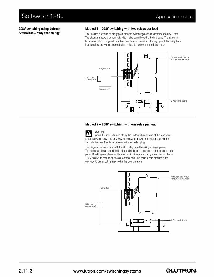
www.lutron.com/switchingsystems2.11.3
Softswitch128™ Application notes
208V switching using Lutron®
Softswitch™ relay technologyMethod 1 – 208V switching with two relays per loadThis method provides an air-gap off for both switch legs and is recommended by Lutron.The diagram shows a Lutron Softswitch relay panel breaking both phases. The same canbe accomplished using a distribution panel and a Lutron feedthrough panel. Breaking bothlegs requires the two relays controlling a load to be programmed the same.
Method 2 – 208V switching with one relay per load
Warning!When the light is turned off by the Softswitch relay one of the load wires
is still live with 120V. The only way to remove all power to the load is using the two pole breaker. This is recommended when relamping.
The diagram shows a Lutron Softswitch relay panel breaking a single phase.The same can be accomplished using a distribution panel and a Lutron feedthrough panel. Breaking one phase will turn off a circuit when properly wired, but will leave 120V relative to ground at one side of the load. The double pole breaker is the only way to break both phases with this configuration.
Softswitch Relay Modulecontains four 16A relays
2 Pole Circuit Breaker
Relay Output 3
Relay Output 1
208V Load(phase-phase)
Softswitch Relay Modulecontains four 16A relays
2 Pole Circuit Breaker
Relay Output 1
208V Load(phase-phase)

www.lutron.com/switchingsystems 2.11.4
Softswitch128™ Application notes
Using a daylight sensor withthe Softswitch128 system
Overview
The Softswitch128 controller can accept Class 2 dry contact closures to automatically control lights.This contact closure can come from a daylight sensor if daylight control is required. The wiring details for an outdoor/indoor daylight sensor are shown below.
WiringThe wiring diagram shows a Softswitch128 controller wired to a daylight sensor single level controller. TheSoftswitch128 controller can be programmed to allow the daylight sensor controlled contact closure toturn off or on lights. The details for programming the Softswitch128 controller can be found in theSoftswitch128 Setup and Maintenance Guide.
24 VAC Transformer
Common
24 VAC
Earth Ground
Softswitch128 Controller locatedinside the switching panel
Daylight Sensor:PC5AD (Outdoor) orPC9AD (Indoor)
1. Contact Closure 12. Common3. Contact Closure 24. Common
Daylight SensorSingle LevelController
1 2 3 4 D 5 1 2 3 4
1 2 3 4 5
1 2

www.lutron.com/switchingsystems2.11.5
Softswitch128™ Application notes
480V switching using lutron®
Softswitch relay technologyThe Lutron Softswitch relay module is not capable of switching a 480V load. 480V load switching isaccomplished with a Lutron Softswitch relay module and a 480V contactor that are assembled into aSoftswitch relay panel. The contactor is controlled by one of the relay outputs on a Softswitch modulepowered at 277V. The left side of the contactor allows for contractor wiring of a 2 pole 277V breaker
Note: Contact customer service to quote a panel capable of switching 480V loads.
277V Breakers1-pole and 2-pole277V Breakers required per 480V load.Located in a panel boardseparate to the Lutronpanel
SoftswitchRelay Modulecontains four16A relays
480VContactermounted in aLutron paneland prewiredto a Softswitchrelay module
480V Load(phase-phase)
Neutral Bus
1-polebreaker
2-polebreaker
and 480V load. This solution is detailed in the diagram below.

www.lutron.com/switchingsystems 2.11.6
Softswitch128™ Application notes
Controlling Softswitch128 using theRadioRA® telephone interface
Overview
The Softswitch128 switching system can be controlled from any location worldwide by using the RadioRATelephone Interface (RA-RC-3). The Telephone Interface provides capability to activate the followingactions: toggle circuits, select a pattern, or turn off (with a specified time delay). By connecting the out-puts from the Telephone Interface to the contact closure inputs on the Softswitch128 Controller, pressingbuttons on any telephone will activate the desired action.
Wiring
The wiring diagram below shows how to wire up to two outputs from the RadioRA Telephone Interface tothe contact closure inputs on the Softswitch128 Controller (located in the switching panel). The TelephoneInterface provides up to three outputs - each Softswitch128 Controller provides two contact closureinputs. A dedicated phone line is recommended, but not required.
Talk Battery
Not used forthis application
To additionalRA-RC-3 units(if used)
Telephone InterfaceModel No. RA-RC-3
*The RA-RC-3 monitors forDTMF tones anytime thephone line is in an off-hookcondition. This allows for itsuse in conjunction with ananswering machine.
To C.O.telephoneline
To in-house phones* oradditional RA-RC-3
To 12 VDCTransformer (supplied)
Softswitch128Controller
1 2 3 4 D 5 1 2 3 4
Close-up ofRA-RC-3Terminals
Action 1
CommonAction 2Common
Terminals
RJ-IN RJ-OUT
OFF ON
1 2 3 4 5 6 7 8 9 10NO C NO C NO C NC A - +
Relay 1 Relay 2 Relay 3 12VDC

www.lutron.com/switchingsystems2.11.7
Softswitch128™ Application notes
Controlling Softswitch128 using theRadioRA® telephone interface
Using an OMX-AV
Each Softswitch128 Controller provides two contact closure inputs. If additional inputs are required, anOMX-AV interface may be used in conjunction with the RA-RC-3 Telephone Interface. See below for wiringand programming using the OMX-AV.
Program contact closure inputs of OMX-AV using Softswitch128 Controller:
1) From the main menu, select Control Station Setup.
2) Select the address of the OMX-AV to configure.
3) Change the type to OMX-AV.
4) Select the contact closure input number to configure (OMX-AV provides 5 inputs).
5) Select the Closure Action.
6) Select the type of action to perfom (Toggle, Pattern, or Delay to Off) when a contactclosure is received. Refer to the Softswitch128 Setup and Maintenance Guide for adescription of these types.
7) Program the action and the circuits accordingly.
8) Repeat steps 1 to 7 for each OMX-AV input.
Talk Battery
Not used forthis application
To additionalRA-RC-3 units(if used)
RA-RC-3Terminals
Softswitch128 Low Voltage Wiring Link
Softswitch128 Controller
1 2 3 4 D 5 1 2 3 4
OFF ON
1 2 3 4 5 6 7 8 9 10
NO C NO C NO C NC A - +
Relay 1 Relay 2 Relay 3 12VDC
Inputs Outputs
COM +V
MUX
MUX
Prog
ram
Sw
itch
MUX Link1 2 3 4 C 1 2 3 4 5 1 2 3 4 5 C
Actio
n 1
Com
mon
Actio
n 2
Com
mon
Actio
n 3
Com
mon

www.lutron.com/switchingsystems 2.11.8
Using a Sentry Switch®
with Softswitch128Overview
A Sentry Switch switch may be used with a Softswitch128 system to provide local, line-voltage overridecontrol of lighting. During normal operation, the switch can be used to turn lighting on and off. When theSoftswitch128 time clock turns lighting off in afterhours mode, the switch automatically resets itself to theoff position. A user may then manually override afterhours mode, turning the lights back on using theSentry Switch switch.
Important Note
The Sentry Switch switch is neither manufactured nor provided by Lutron. Its performance cannot be guaranteed by Lutron.
Controlling Softswitch128 using theRadioRA® telephone interface
Operating the RA-RC-3
1 3 Beeps indicates an invalid entry or error.
The RA-RC-3 will provide 4 Beeps and hang up if 20 seconds elapse without an entry. Repeat steps 1 and 2 to continue.
1. Call the line to which the RA-RC-3is connected.
The RA-RC-3 will answer after the set number ofrings. Note: Lutron does not recommend operatingthe RA-RC-3 from in-house phones. Entering *followed by certain digits on in-house phones maychange phone service functions(i.e., disable call waiting).
Press Response
2 Beeps
2. Enter the operatingaccess code.
This code was set in Step 4 previously. * 6 digits 2 Beeps
3. Activate an action.Allow 5 secondsbetween activatingany two actions.
Enter any action number (1, 2, or 3) and then 2.
• Pressing 12 activates Action 1.
• Pressing 22 activates Action 2.
• Pressing 32 activates Action 3.
12 / 22 / 32 2 Beeps1
4. Hang up the phone.
Softswitch128™ Application notes
Neutral
Switched Hot
Sentry Switch
Load
Softswitch128 Panel
Softswitch128 Controller/Time Clock

www.lutron.com/switchingsystems2.11.9
Power panels in outdoor applications Overview
Lutron Power Panels are designed for indoor use and are constructed as NEMA Type 1 Enclosures. ANEMA Type 1 Enclosure is defined as: constructed for indoor use to provide a degree of protection topersonnel against incidental contact with the enclosed equipment and to provide a degree of protectionagainst falling dirt (from NEMA 250-2003).
In certain applications, Lutron Power Panels may require a greater degree of protection against dirt, dust,water, etc. due to their intended mounting location. Lutron Power Panels may be installed in a secondaryenclosure with a higher NEMA rating provided that the following conditions are met:
1) The secondary enclosure is of a suitable NEMA type rating for the intended installation location.2) Lutron requirements for environmental conditions of the Power Panel are maintained.
All Lutron Power Panels must be operated within the following environmental conditions:
1) Ambient temperature: 32°-104°F (0°- 40°C)2) Non-condensing relative humidity less than 90%
Failure to maintain these conditions may affect the performance and the operating lifetime of theequipment.
Lutron does not supply Power Panels in secondary enclosures with higher NEMA ratings.Manufacturers of NEMA rated enclosures include (but are not limited to):
Hoffman www.hoffmanonline.comTrident Custom Enclosures www.tridentce.com
Numerous NEMA enclosure ratings are available, each specifying a degree of protection against specificenvironmental conditions. If a secondary enclosure is required, it must be specified and installed inaccordance with the manufacturer's requirements, accounting for the actual environmental conditionsto which it will be exposed. The heat dissipation of the Power Panel must also be considered. Consultthe appropriate Lutron technical documents for heat dissipation data for Power Panels. Regardless ofthe enclosure type, the environmental conditions for Lutron Power Panels (listed above) mustalways be maintained.
Softswitch128™ Application notes

www.lutron.com/switchingsystems 2.11.10
Linking multiple occupancy sensors to a wallstation
Softswitch128™ Application notes
Wiring
Occupancy Sensor Wiring (One occupancy sensor)
• Use low-voltage PELV (Class 2: USA) wiring toconnect the Occupancy Sensor to the wallstation.
Occupancy Sensor Wiring (More than one Occupancy sensor)
• Use low-voltage PELV (Class 2: USA) wiring toconnect the Occupancy Sensor to the wallstation.
Occupancy sensorRear of seeTouch
Wallstation
Common
Signal
24 V(3) #18 AWG
(1.0mm2)
CBA
4321
Occupancy sensorHot
Neutral
Black
White
RedRed
Blue (signal)Red (+20-24 V )
Black(common)
Note: Maximum 3 Occupancy Sensors
120/277/347 V~ 60 Hz;230 V~ 50/60 Hz
Rear of Wallstation
Common
Signal
24 V
(3) #18 AWG(1.0mm2)
CBA
4321

www.lutron.com
Lutron Electronics Co., Inc.7200 Suter RoadCoopersburg, PA 18036-1299
World Headquarters 1.610.282.3800
Barcelona I Beijing I Berlin I Guangzhou I Hong Kong I London I Madrid I Mexico City IMilan I Paris I Rome I São Paulo I Shanghai I Singapore I Tokyo
Technical Support Center 1.800.523.9466Customer Service 1.888.LUTRON1
© 08/2006 Lutron Electronics Co., Inc. I Made and printed in the U.S.A. I P/N 367-860