soft matter interfaces (smi) beamline (12id) - instrument … · soft matter interfaces (smi)...
TRANSCRIPT

1
Soft Matter Interfaces (SMI) Beamline (12-ID) Instrument Readiness Overview
Instrument Readiness Review October 19, 2016 Elaine DiMasi, Lead Beamline Scientist for SMI On behalf of NEXT Project, SMI Beamline Development Team, and IRR Readiness Team
1

2
Outline
• Background • Scientific Program, SMI Scope, Beamline Layout, Commissioning Sequence
• Pillar I: Documentation: • Ray tracing, FLUKA Calculation, RSC Review, Design Reviews, Hazard
Identification and Mitigation
• Pillar II: Hardware –Radiation Safety Components, Other Credited Controls, Utilities, EPS,
Controls, Diagnostics
• Pillar III: Personnel –Beamline Commissioning Team

3
NEXT Project and SMI Beamline Timeline
• The NEXT Project (NSLS-II Experimental Tools) –Scope: 5 beamlines (and 1 beamline design) –DOE funded project –Timeline:
• CD-0 start date: May 2010 • Early completion date: January 2017 • CD-4 date: September 2017
• SMI Beamline: –Scope: Photon Delivery System, infrastructure, and sample and
detector positioning –SMI beamline construction combines procurements with in-house
mechanical design and fabrication
4
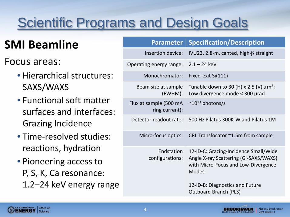
Scientific Programs and Design Goals SMI Beamline Focus areas:
• Hierarchical structures: SAXS/WAXS
• Functional soft matter surfaces and interfaces: Grazing Incidence
• Time-resolved studies: reactions, hydration
• Pioneering access to P, S, K, Ca resonance: 1.2–24 keV energy range
Parameter Specification/Description Insertion device: IVU23, 2.8-m, canted, high-β straight
Operating energy range: 2.1 – 24 keV
Monochromator: Fixed-exit Si(111)
Beam size at sample (FWHM):
Tunable down to 30 (H) x 2.5 (V) µm2; Low divergence mode < 300 µrad
Flux at sample (500 mA ring current):
~1013 photons/s
Detector readout rate: 500 Hz Pilatus 300K-W and Pilatus 1M
Micro-focus optics: CRL Transfocator ~1.5m from sample
Endstation configurations:
12-ID-C: Grazing-Incidence Small/Wide Angle X-ray Scattering (GI-SAXS/WAXS) with Micro-Focus and Low-Divergence Modes 12-ID-B: Diagnostics and Future Outboard Branch (PLS)

5
IRR Scope
IRR scope includes: 1. Photon Delivery System (GV2 through 12-ID-C) 2. Enclosures: 12-ID-A, -B, -B-1, and -C 3. Motion and monitoring system of PDS 4. EPS (related to PDS), PPS, all infrastructure necessary for
commissioning Photon Delivery System 5. WAXS Assembly: Sample and Detector Positioners
IRR scope exclusions: 1. SAXS Assembly in 12-ID-C 2. Pilatus Detectors 3. X-ray Beam Position Monitors 4. Beam conditioning (attenuators)
SMI WAXS assembly

6
Self-identified Pre-start Findings
Pre-start findings: None
Post-start findings: None
7
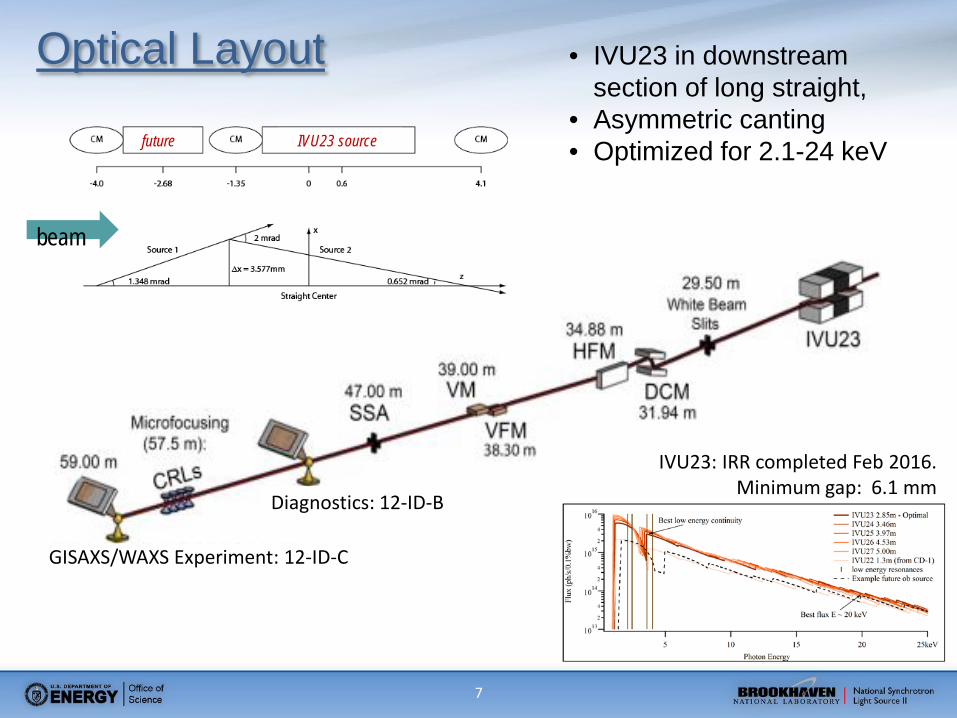
GISAXS/WAXS Experiment: 12-ID-C
Diagnostics: 12-ID-B
• IVU23 in downstream section of long straight,
• Asymmetric canting • Optimized for 2.1-24 keV
IVU23: IRR completed Feb 2016. Minimum gap: 6.1 mm
Optical Layout
beam
IVU23 source future

8
Beamline Layout
• First Optics Enclosure: 12-ID-A (lead lined hutch)
• Steel Hutches: 12-ID-C: GI-SAXS/WAXS 12-ID-B: Diagnostics
9
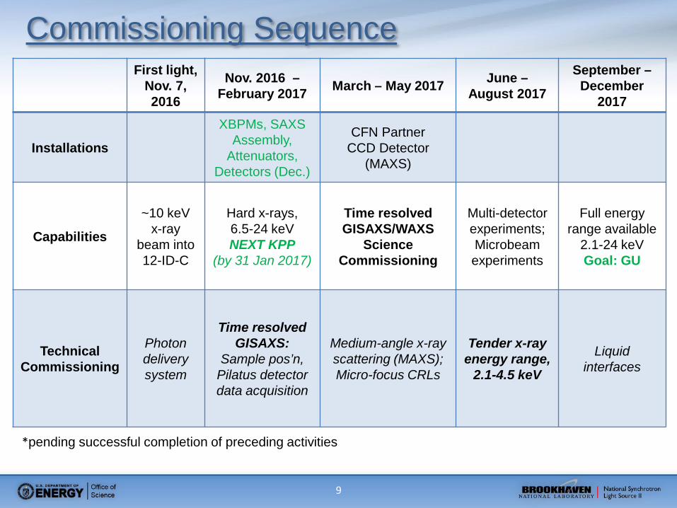
Commissioning Sequence First light,
Nov. 7, 2016
Nov. 2016 – February 2017 March – May 2017 June –
August 2017
September – December
2017
Installations
XBPMs, SAXS Assembly,
Attenuators, Detectors (Dec.)
CFN Partner CCD Detector
(MAXS)
Capabilities
~10 keV x-ray
beam into 12-ID-C
Hard x-rays, 6.5-24 keV NEXT KPP
(by 31 Jan 2017)
Time resolved GISAXS/WAXS
Science Commissioning
Multi-detector experiments; Microbeam experiments
Full energy range available
2.1-24 keV Goal: GU
Technical Commissioning
Photon delivery system
Time resolved GISAXS:
Sample pos’n, Pilatus detector data acquisition
Medium-angle x-ray scattering (MAXS); Micro-focus CRLs
Tender x-ray energy range,
2.1-4.5 keV
Liquid interfaces
*pending successful completion of preceding activities

10
Pillar I: Documentation

11
Ray Tracing PD-SMI-RAYT-0001
• Prepared using Synchrotron and Bremsstrahlung Ray Trace Procedure (PS-C-XFD-PRC-008)
• Includes absolute positioning (±0.22 mm) and manufacturing (±0.14 mm) tolerances; as-surveyed component locations are used.

12
Shielding Concept: Dual Aperture Masks • SMI constructed with dual
aperture masks and wide stops for drop-in outboard upgrade
• PPS aperture and Fixed Aperture Mask ensure that wide SR fan ends at White Beam Stop
• Outboard branch constrained to similar optics (100µrad FAM, 25mm DCM step-up)
Horizontal, Synchr. Max Fan Ray Trace
13
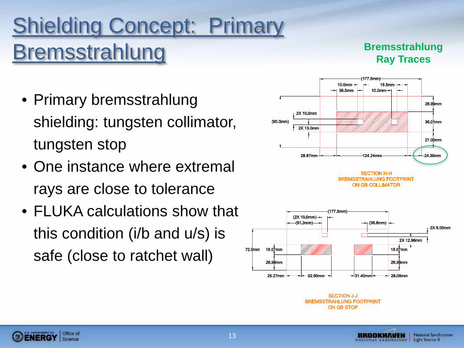
Shielding Concept: Primary Bremsstrahlung
• Primary bremsstrahlung shielding: tungsten collimator, tungsten stop
• One instance where extremal rays are close to tolerance
• FLUKA calculations show that this condition (i/b and u/s) is safe (close to ratchet wall)
Bremsstrahlung Ray Traces

14
Shielding Concept: Secondary Bremsstrahlung (SGB)
Primary GB on WB Slit
dose on contact with downstream wall ≤ 0.4 mrem/hr)
• Geometric analysis indicated that SGB shields would be necessary
• Shield 1: after WB Slits • Shield 2: after DCM • FLUKA analysis
performed with shields in model
• GB on movable optics scatters significantly

15
Review held on 11 Oct. 2016 • Findings:
Doses at FOE d/s wall in range 0.05-0.4 mrem/hr on contact (SGB from movable optics)
• Response: Incorporated into Radiation Survey Plan.
15
RSC Review

16
• NSLSII-12ID-PRC-001
• GB Radiation Survey: IVU gap open, FE slits wide • Integrity 12-ID-A, GB on fixed components • GB on movable components (WB Slits, DCM 1st crystal)
• Synchrotron radiation survey: IVU gap closed, FE slits wide • Integrity 12-ID-A, white beam on fixed components • White beam on movable components
• Monochromatic beam surveys: • Configuration with beam in 12-ID-C experiment • Configuration with beam in 12-ID-B diagnostic
• Plan first comprehensive radiation survey (CRS) at 100mA; will
enable SMI to work with ring current ≤ 300mA
16
Radiation Survey Procedure

17
• Documents maintained in Vault and Sharepoint https://ps.bnl.gov/phot/BeamlineSupportDocs/SMI
• All items closed out • Review flow:
17
Design Reviews DOE Review Process
BAT Meetings
Formal PDR/FDR Beamline
Package FDR Internal Design Reviews
CD-0, CD-1, CD-2, CD-3, and intermittent status reviews
5 BAT meetings • CD-2 was FDR for SMI • Remaining endstation
design work treated by internal reviews
Held at BNL, with Subject Matter Experts attending
• Radiation safety • Thermal mgt / FEA • 2 ES Design reviews • 2 Optics reviews
Recommendations tracked by project management
Recommendations tracked by project management
Recommendations tracked by project management
Recommendations directly implemented into design (with QA as representative)
Tracked by ATS
Technical, schedule & financial
Technical Technical, Schedule, & Safety
Technical & Safety Technical & Safety
Review Reports BAT Reports PDR, FDR, & Reports Meeting Notes & Reports Reports
Beamline PDR/FDR
Package FDR Package FDR
Package FDR Package FDR
Package FDR
Internal design review Internal design review
USI screening Integrated Safety Management

18 18
Hazard Identification and Mitigation
• USI evaluation is negative • Relevant BNL/NSLS-II safety procedures and practices are
followed during design/construction and commissioning (SBMS & ISM)
Hazard Mitigation Radiation Shielding, PPS, ARM
Fire Future: fire suppression and fire alarm system in 4-ID-D for gas handling system (ESR)
Cryogenics ODH system installed in 12-ID-A
Hazardous material - Lead Painted and/or covered
Pressure safety vessel FEA calculations, over-pressure tests (if appropriate), burst discs
Electrical EEI, grounding, installation according to code

19
Pillar II: Hardware

20
Shielded Enclosures and Transport Pipes
• Lead-shielded FOE: 10 mm roof, 18 mm sidewall, 50 mm downstream wall • Steel hutches B, C, and D: 3 mm roof, 6 mm side and downstream walls • Lead-shielded beam transport pipes, pump enclosures, and flange covers: 5 mm • Lead-shielded hutch interfaces: ≥ 10 mm • Hutch doors and one or more labyrinths per hutch are PPS-interlocked • Removable shielded beampipe in 12-ID-B, constructed like walkway transport
Inboard and outboard beam penetrations in 12-ID-B-1
Removable beam stop block and shielded beam pipe in 12-ID-B

21
Radiation Safety Components
1. PPS Aperture/ Fixed Aperture Mask 2. GB Collimator 3. (White Beam Slits. Movable, SGB scatterers, not rad safety component) 4. (Pinhole aperture. FUTURE movable device, SGB analysis only, not RSCmpt, not installed) 5. SGB Shield 1 6. (DCM. Movable, SGB scatterer, not rad safety component) 7. SGB Shield 2 8. White Beam Stop 9. GB Stop 10. Photon Shutter 11. Guillotine
Mono beam enclosures: 1. Guillotines 2. Beam Stops
22 22
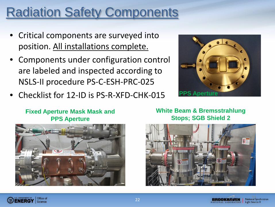
Radiation Safety Components
PPS Aperture
White Beam & Bremsstrahlung Stops; SGB Shield 2
Fixed Aperture Mask Mask and PPS Aperture
• Critical components are surveyed into position. All installations complete.
• Components under configuration control are labeled and inspected according to NSLS-II procedure PS-C-ESH-PRC-025
• Checklist for 12-ID is PS-R-XFD-CHK-015

23 23
Other Credited Safety Components
(c) Oxygen Deficiency Hazard (ODH) Monitor
(a) Area Radiation Monitor (ARM) at 12-ID FE sliding door
(b) ARM on 12-ID-A near door
24 24
Utilities
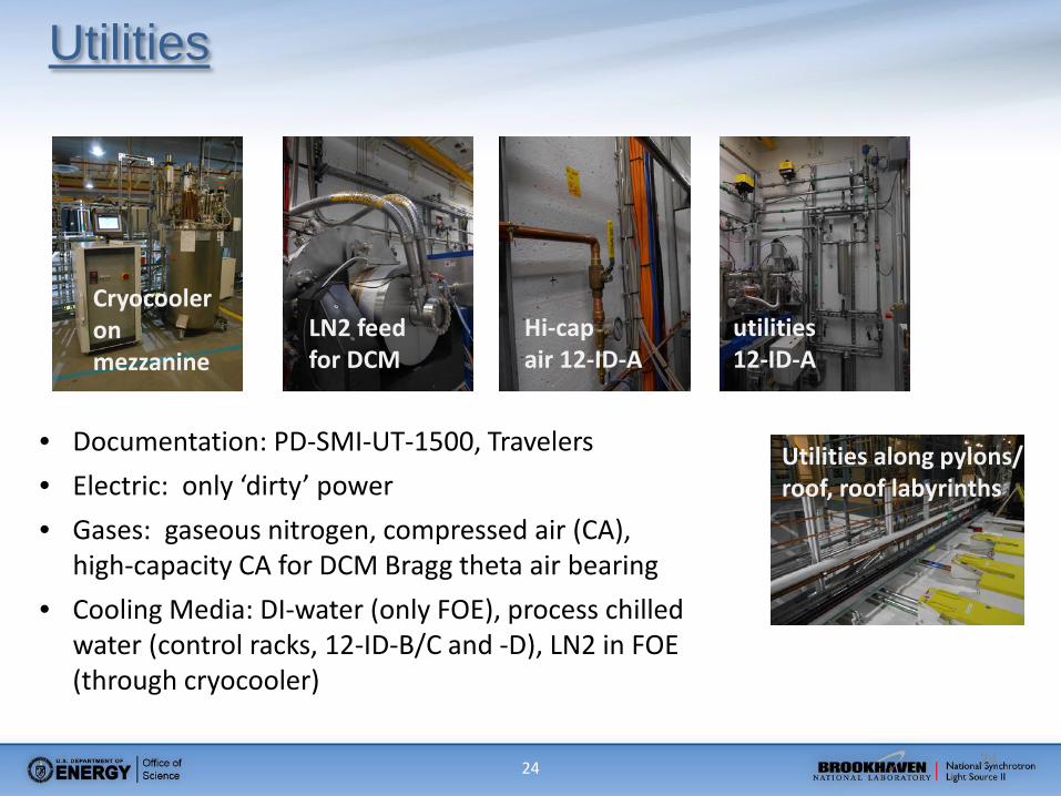
• Documentation: PD-SMI-UT-1500, Travelers • Electric: only ‘dirty’ power • Gases: gaseous nitrogen, compressed air (CA),
high-capacity CA for DCM Bragg theta air bearing • Cooling Media: DI-water (only FOE), process chilled
water (control racks, 12-ID-B/C and -D), LN2 in FOE (through cryocooler)
LN2 feed for DCM
Cryocooler on mezzanine
Utilities along pylons/ roof, roof labyrinths
Hi-cap air 12-ID-A
utilities 12-ID-A
25 25
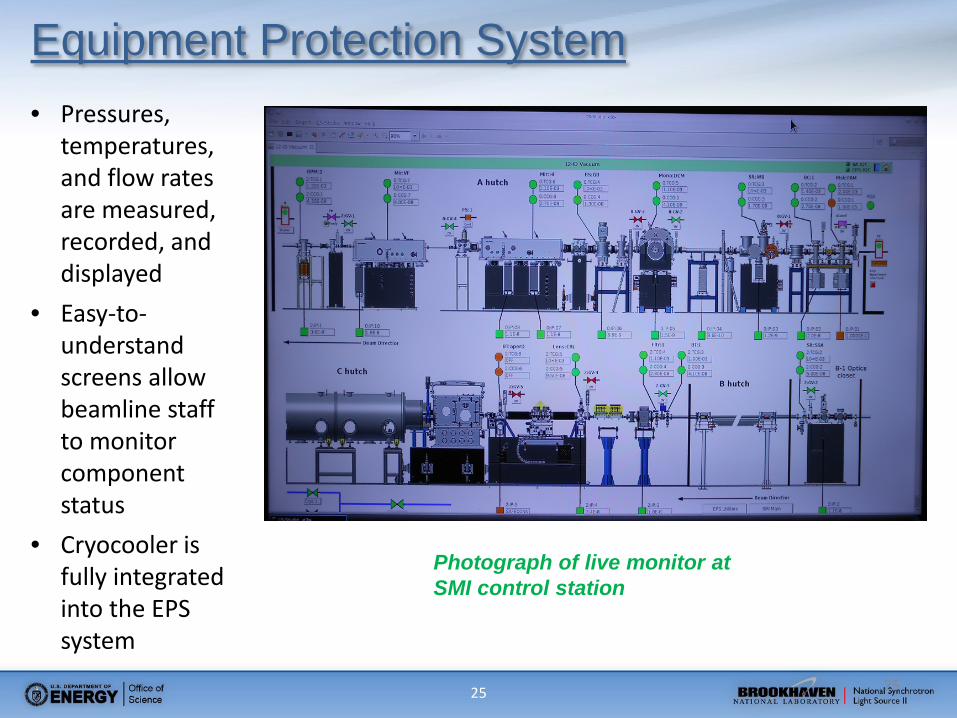
Equipment Protection System • Pressures,
temperatures, and flow rates are measured, recorded, and displayed
• Easy-to-understand screens allow beamline staff to monitor component status
• Cryocooler is fully integrated into the EPS system
Photograph of live monitor at SMI control station
26 26
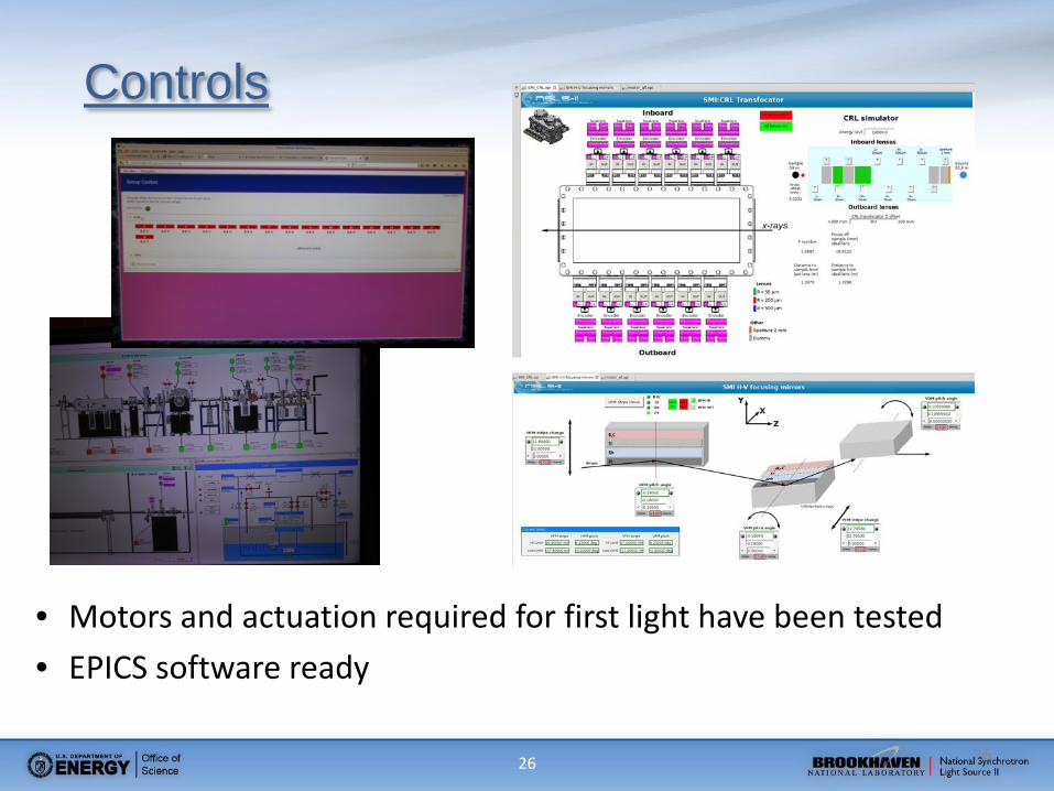
Controls
• Motors and actuation required for first light have been tested • EPICS software ready

27 27
Diagnostics
• IRR scope: • White beam slit photocurrent • White beam stop phosphor + camera • HFM stripe photocurrent • Retractable fluorescent screen after HFM • Secondary Source Aperture slit photocurrent • Photodiodes + cameras in diagnostic and sample positions
• November/December installation: • XBPM1 after DCM, XBPM2 after VFM, XBPM3 before SSA

28
Pillar III: Staff
29
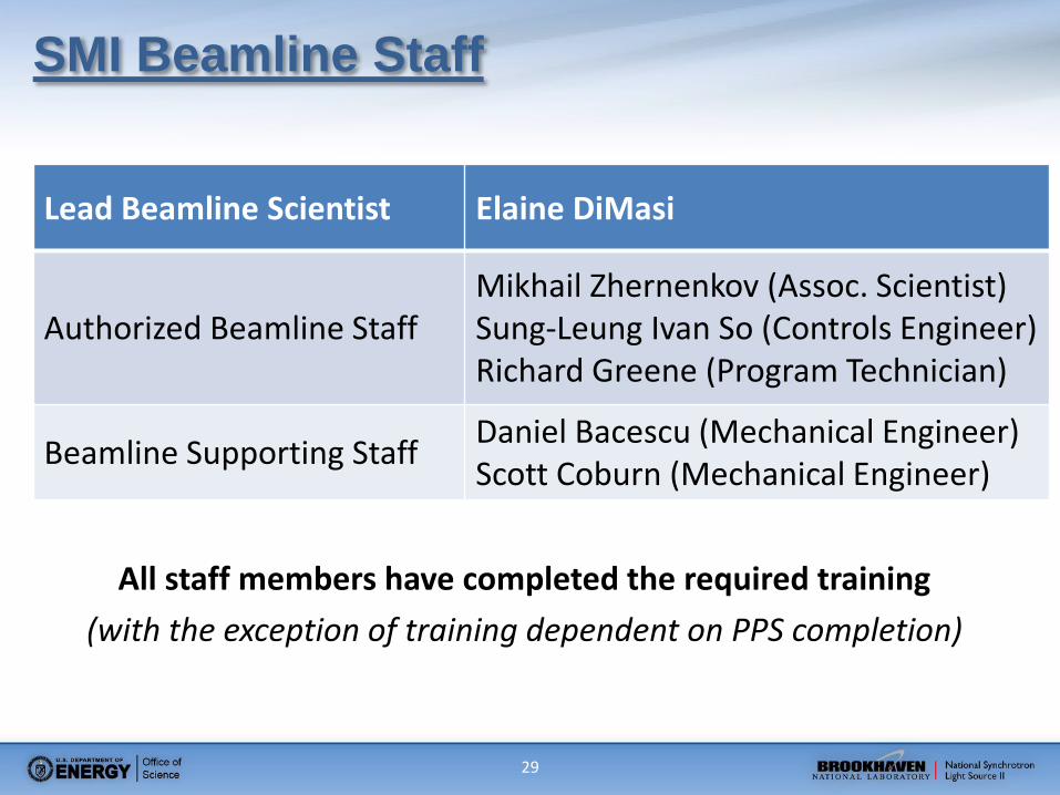
SMI Beamline Staff
Lead Beamline Scientist Elaine DiMasi
Authorized Beamline Staff Mikhail Zhernenkov (Assoc. Scientist) Sung-Leung Ivan So (Controls Engineer) Richard Greene (Program Technician)
Beamline Supporting Staff Daniel Bacescu (Mechanical Engineer) Scott Coburn (Mechanical Engineer)
All staff members have completed the required training (with the exception of training dependent on PPS completion)

30
Summary
• The Photon Delivery System + WAXS Ass’y in IRR scope • Commissioning will be carried out in five stages:
• Photon Delivery System • Time Resolved GISAXS • Multi-detector acquisition + Microfocusing • Tender X-ray Energies • Liquid Interfaces
• Beamline is ready for first light • Endstation installation is performed in parallel with
commissioning activities