soft gripper driven by a solenoid actuator
TRANSCRIPT

Soft Gripper Driven by a Solenoid Actuator
by
Sepehr Sheikholeslami
B.A.Sc., Simon Fraser University, 2014
Thesis Submitted in Partial Fulfillment of the
Requirements for the Degree of
Master of Applied Science
in the
School of Mechatronic Systems Engineering
Faculty of Applied Sciences
© Sepehr Sheikholeslami 2019
SIMON FRASER UNIVERSITY
Fall 2019
Copyright in this work rests with the author. Please ensure that any reproduction or re-use is done in accordance with the relevant national copyright legislation.

ii
Approval
Name: Sepehr Sheikholeslami
Degree: Master of Applied Science
Title: Soft Gripper Driven by a Solenoid Actuator
Examining Committee: Chair: Helen Bailey Lecturer
Carlo Menon Senior Supervisor Professor
Flavio Firmani Supervisor Lecturer
Woo Soo Kim Internal Examiner Associate Professor
Date Defended/Approved: November 28, 2019

iii
Abstract
In the past thirty years, robotics technology has become well-established in the
manufacturing industry for reducing worker ergonomic stress and workload by performing
operations such as picking and placing objects from a location to another, quickly,
repetitively, and accurately. As we continue to integrate robots as versatile aids for
industry, it is important to develop mechanisms that facilitate seamless cooperation
between humans and robot assistants (RAs).
Contributions of this thesis include the design and development of a more advanced, yet
simple and cost-effective soft industrial robotic gripper that is scalable, and can be
mounted on a wide range of commonly used robotic arms. The finished gripper prototype
uses inexpensive components, and thus, would be economical to produce while
addressing the needs of industry.
Depending on the application, the developed gripper can outperform the state of the art in
many “pick and place” tasks and is capable of picking up a wide variety of objects in size,
weight, geometry and texture. To be applicable to current industrial warehouse
environments, a series of tests were conducted to evaluate the effectiveness of the gripper
in picking up and placing a set of items commonly available. The developed gripper in this
work was mounted on a KUKA arm, and was tested for gripping objects from delicate ones
such as a light bulb to heavier ones such as a 23 cm x 14 cm x 12 cm pack of eight cans
of soda, weighing around 3 kg with a measured speed of 0.88 m/s.
Keywords: Soft robotic gripper; polymer membrane; delicate objects gripper; variable-
volume chamber; flexible silicone membrane; magnetic gripper

iv
Dedication
To my family for their indefinite support
through all my life

v
Acknowledgements
I would like to thank my senior supervisor, Dr. Carlo Menon for his understanding
and help since day one I started my research. He was the main reason I have start this
research and I am where I am today with this project.
I would also like to thank past and present members of MENRVA research group
who have helped me throughout my research.
Finally, I would like to thank my parents and sister who encouraged me in taking
this path and supported me through all these years. The only reason I reached to this point
in my life is my parent’s moral and financial support.

vi
Table of Contents
Approval .......................................................................................................................... ii
Abstract .......................................................................................................................... iii
Dedication ...................................................................................................................... iv
Acknowledgements ......................................................................................................... v
Table of Contents ........................................................................................................... vi
List of Tables ................................................................................................................. vii
List of Figures................................................................................................................ viii
List of Acronyms .............................................................................................................. x
Chapter 1. Introduction .............................................................................................. 1
1.1. Background and Motivations ................................................................................. 1
1.2. Objectives.............................................................................................................. 3
1.3. Thesis Layout ........................................................................................................ 4
Chapter 2. Literature Review ..................................................................................... 5
Chapter 3. Design Considerations .......................................................................... 10
3.1. Gripper Configuration .......................................................................................... 10
3.2. Gripper actuation ................................................................................................. 27
3.2.1. Solenoid Actuation ....................................................................................... 27
3.2.2. Coil Experimental Investigation .................................................................... 32
3.2.3. Solenoid Model ............................................................................................ 38
3.2.4. Solenoid Model Verification ......................................................................... 40
3.2.5. Solenoid Design Consideration .................................................................... 41
3.2.6. Solenoid Optimization .................................................................................. 45
3.3. Gripper Soft Membrane ....................................................................................... 50
3.4. Gripper Electronics .............................................................................................. 57
Chapter 4. Testing and Experiments ....................................................................... 61
4.1. Peak power of the gripper .................................................................................... 61
4.2. Force Measurement ............................................................................................ 63
4.3. Actuation Speed .................................................................................................. 66
4.4. Picking up Objects with Different Shapes and Weights ........................................ 66
Chapter 5. Conclusion ............................................................................................. 70
References ................................................................................................................... 72

vii
List of Tables
Table 1: Comparing different versions of the gripper at a glance.......................... 21
Table 2: Different 3D printing methods and their respective material data ............ 26
Table 3: Prototyped coil and magnet actuator ...................................................... 40
Table 4: Constant parameters for the coil and magnet ......................................... 47
Table 5: The Best, Average, and worst Function value obtained using GA, SA, and PS. α, β, and dw for best value are only written in the table. .................. 48
Table 6: Polymer Characteristics [94]................................................................... 51

viii
List of Figures
Figure 3.1: gripper's three main components. Half of the membrane is only shown to illustrate the magnetic shaft .................................................................... 11
Figure 3.2: Gripping process .................................................................................... 13
Figure 3.3: Gripper’s different prototypes and their cross-section view. .................... 14
Figure 3.4: Membrane Installation for versions 2-4 ................................................... 16
Figure 3.5: Assembly to make a custom coil on a custom bobbin ............................ 18
Figure 3.6: Forcing the inflated membrane toward the object by using a clip around the gripper .............................................................................................. 19
Figure 3.7: Final version of the gripper with its shaft is extended and its cross section ............................................................................................................... 20
Figure 3.8: Gripper's body attached to a rotary tool for wrapping the coil ................. 20
Figure 3.9: Exploded and isometric view of the gripper in SolidWorks ...................... 23
Figure 3.10: Sealing Membrane to the shaft ............................................................... 24
Figure 3.11: Overexposure of an ABS part to acetone vapor ..................................... 25
Figure 3.12: Pictures of different stages of gripping an object .................................... 27
Figure 3.13: Cross Section of a solenoid made of a coil and a permanent magnet shaft ............................................................................................................... 28
Figure 3.14: Force sensor attached to a leveling device ............................................. 29
Figure 3.15: Shaft comparison between a solid fill cobalt steel cylinder, a hollow cobalt steel cylinder with 21 mm inside diameter, a solid fill rare earth magnet, and a hollow rare earth magnet with 12.7 mm inside diameter ............... 30
Figure 3.16: Cross section of an energized coil and a set of permanent magnet shafts ............................................................................................................... 31
Figure 3.17: Cross section of a pair of identical coils with two different size magnets 31
Figure 3.18: Actuation force with respect to displacement of the magnetic shaft to the coil ......................................................................................................... 32
Figure 3.19: Comparing actuation force when doubling coil length and keeping everything else constant ......................................................................... 33
Figure 3.20: Comparing actuation force when two shafts with different diameters are used and all other parameters are kept constant .................................... 34
Figure 3.21: Comparing actuation force when two shafts with different lengths are used and all other parameters are kept constant .................................... 35
Figure 3.22: Comparing actuation force when two coils with different lengths are used and all other parameters are kept constant ............................................ 36
Figure 3.23: Comparing three custom wrapped coils using different wire gauges ...... 37
Figure 3.24: Geometrical parameters of the coil and magnet actuator (modified from [80]) ........................................................................................................ 38
Figure 3.25: Comparison of analytical and measured force values using the designed gripper .................................................................................................... 41
Figure 3.26: Normalized force vs center to center distance for different coil ratios ..... 44

ix
Figure 3.27: Normalized force vs center to center distance for different magnet ratios ............................................................................................................... 44
Figure 3.28: Optimized Normalized Force vs Coil's wire diameter .............................. 50
Figure 3.29: Shore Hardness scale (Modified from [95]) ............................................ 52
Figure 3.30: Injection molding prototype to create silicone membrane. a) Full assembled mold, b) Mold inner shell ...................................................... 52
Figure 3.31: EcoFlexTM 00-10 created using an injection molding method .................. 53
Figure 3.32: Different Silicone mold iteration. Silicone was applied using a brush in these molds. ........................................................................................... 54
Figure 3.33: An injection mold Similar to the model of a wine bottle ........................... 56
Figure 3.34: Final Mold prototype ............................................................................... 56
Figure 3.35: Control Box Wiring Diagram ................................................................... 58
Figure 4.1: Peak Power of the gripper. Stages 1 and 4 peak powers are negligible, but stage 2 can be different depending on the current applied. 2.5 A, 1.8 A, and 0.87 A are shown. ....................................................................... 62
Figure 4.2: Force Measurement test setup ............................................................... 63
Figure 4.3: A rubber ball with a tube inserted to create a hole .................................. 64
Figure 4.4: Force measurement results .................................................................... 65
Figure 4.5: Gripping Force VS Gripper's input peak power ....................................... 65
Figure 4.6: Gripper actuation speed vs input power ................................................. 66
Figure 4.7: Picking up objects with various shapes and weights. ............................. 68
Figure 4.8: Gripping various objects and a picture of their contact point with the gripper .................................................................................................... 69

x
List of Acronyms
ABS Acrylonitrile butadiene styrene
AWG American wire gauge
CAD Computer-Aided Drafting
CNC Computer Numerical Control
CPU Central Processing Unit
DEA Dielectric Elastomer Actuator
DOF Degree of Freedom
FDM Fused Deposition Modeling
FEA Fluidic Elastomer Actuator
GA Genetic Algorithm
ID Inside Diameter
KUKA Keller und Knappich Augsburg
OD Outside Diameter
PS Pattern Search
RAs Robot Assistants
SA Simulated Annealing
SFU Simon Fraser University
SLA Stereolithography
SLS Selective Laser Sintering

1
Chapter 1. Introduction
This chapter starts with explaining more about the background and motivation for
researching a soft gripper in section 1.1. It then lays out the objectives for this thesis in
section 1.2. In section 1.3, the layout for the rest of chapters in this thesis is presented.
1.1. Background and Motivations
Factories have automation systems for all kinds of tasks such as assembling cars,
sorting and packing food or medicine, or working alongside human for doing complex and
precise tasks. A necessary part of production industry has been robots starting 20th
century [1]. The rise in population creates the need for using more robots and automated
manufacturing. Robots are already being used in factories to replace humans in doing
jobs such as repetitive, hazardous, or dirty ones [2]. Using robots increases both the
product quality and the factory’s profitability. Some precise and small parts assembly tasks
require more robots to be used in assembly lines. Hence collaborative robots to work
alongside humans become attractive due to both the limited space in factories and higher
flexibility in assembly lines [3]. This need is specially more attractive in industries with
frequent product change like consumer electronics [3]. Hence, due to the limited space in
factories and variability of tasks, some robots will have to work alongside human or be
guided actively by human [4]. The cooperation of human and robots can increase the
productivity of assembly lines and reduce the number of breaks and exhaustion. In one
assembly line, robots can handle the repetitive simple tasks and human can handle more
complex tasks [4].
Increasing need for using robots to collaborate with human and do human tasks
that normally require handling with hands, brings more attention toward robotic grippers
[5]. Robotic grippers have been used in numerous applications, such as surgical
operations [6], or industrial use where robots are used to increase production capacity [7].
UNIMATE industrial robot was the first robot used in an assembly plant in 1961 [7], and
ever since many companies have researched and industrialised grippers with various
drive mechanisms [7]. Another application of robotic grippers is in gripping fragile objects

2
by incorporating various sensors [7] such as force feedback sensor to control the pressure
applied by the robot and not damage the object being picked like grippers for food industry
[8].
In general gripping process is achieved by gripper approaching the object,
contacting the object either physically or by a force field generation, securing the object
by increasing the force of the gripper, moving the object, and finally releasing it [9].
Different grasping methods have been developed during the past decade to pick objects
ranging from big and heavy ones to micro size objects. Some of these grasping principles
are mechanical grippers which are widely used in the industry, electrostatic grippers to
manipulate and assemble micro structures [10], or Bernoulli grippers which work with the
concept of air flow [9]. Research in grippers have evolved impressively in recent years,
hence new challenging grippers such as adaptive grippers or grippers using smart material
are being studied and developed [7].
One interesting field that is drastically improving, is the field of soft grippers to
handle delicate objects such as fruits [11]. In contrast to most manufacturing robots which
are stiff so that they can perform fast and precise operations, soft grippers have a soft and
deformable end effector to interact with objects [12]. Some soft grippers that has been
recently developed are inspired by animal body structure, such as grippers having a sac
filled with granular material and using vacuum pressure to jam the material for gripping
[13], [14], or a soft robot gripper based on octopus structure [15]. Most commercially
available grippers have limits such as the need to use an external vacuum pumps for
actuation [13], or not having enough gripping speed. Hence, comes the need for robots
that are fast and versatile, so they can be easily used by any person and does not need
complex structure to set them up.
The gripper should have a velocity suitable for collaborative robots. For instance,
OnRobot has three commercially available grippers called RG2, RG6, and RG2-FT with
maximum gripping speeds of 127 mm/s, 160 mm/s, and 184 mm/s respectively. These
robots were specifically designed for collaborative robots. The proposed gripper should
therefore have a similar velocity (e.g. 0.2m/s) [16].

3
1.2. Objectives
The present work is about designing a gripper that can pick and place various
objects such as delicate ones like fruits without damaging them. The gripper is intended
to have strong gripping force, fast actuation, yet soft to interact with wide range of objects.
Based on these requirements, this thesis has 2 main objectives.
Objective 1 is to design and fabricate a soft gripper which is:
a) Compact (i.e. have about the same size volume of a gripper used for
collaborative robots)
b) Able to grasp objects having different shapes
Objective 2 is to design an actuator for the proposed gripper that:
a) Does not require external actuation source (e.g. pressured air line)
b) Has a velocity higher than 0.2 m/s
c) Generates a force suitable to grasp lightweight and medium weight (e.g.
<4 kg) objects

4
1.3. Thesis Layout
Chapter 2 is a literature review of robotic manipulators and then it is narrowed
down to wide range of robotic grippers, and then it is further narrowed down to soft
grippers.
In chapter 3, the gripper design and electronics are explained to meet both
objective 1 and objective 2. Each sub section in this chapter gives detailed explanation
about each main component to make a working gripper ready for measurement and
testing.
Chapter 4, investigates functionality of the gripper by doing some testing and
evaluations to confirm achievement of objective 1 and objective 2. Each section shows
the result of evaluations done on the finalized prototype. At the end of chapter, some
pictures of an actual test using a KUKA robot to pick and place wide range of objects is
shown.
Chapter 5 concludes this thesis and explains how the objectives of this work are
met.

5
Chapter 2. Literature Review
This chapter does a detailed literature review about robotic manipulator and then
narrows down to robotic grippers and soft grippers.
Robotic research existed for at least 100 years. After some development in
designing robots, the need for robotic manipulator arises. Developing dexterous robotic
manipulators started roughly about 58 years ago [17]. Many robotic hands were developed
with different actuation systems, and all had their own advantages and disadvantages.
Depending on different applications different robotic hands were developed. But
developing more advanced anthropomorphic robotic hands started about 25 years ago
[18]. Based on application of the robot hand, different design parameters such as degree
of freedom (DOF) and number of actuators need to be defined. The preference is to
achieve more DOF with less actuators, and the preferred method of actuations are electric,
pneumatic muscles, and pneumatic cylinders at 75%, 19% and 6% respectively [18]. Most
electronic grippers basically have their main components to be motors, sensors, and a
controller to regulate the actuation depending on readings of the sensors.
Anthropomorphic grippers are categorized as active grippers imitating human
hand in gripping objects [19]. A good example of an anthropomorphic gripper is the DLR
Hand Arm System that has about 19 DOF in total and 52 motors [20]. To mimic the
functionality of a hand, these grippers need to have a high DOF which leads to the need
for algorithms to control the grasping motion of grippers with multi-fingers [21], [22] and
this adds complexity to the system [23].
Robots are used mostly for repetitive job in the industry. Grippers are the end tool
for robots in handling objects. With the need to pick different objects comes the need for
flexible grippers. Typically, in production lines each gripper is made specifically for a
specific type of product, and it needs to be modified to handle a different item [24].
Most of the grippers in the industry are created for specific tasks either complex or
simple. But these grippers are not designed to adapt to the shape of different objects.
Therefore, there is a need to create more adaptable grippers to grasp a wide range of

6
objects rather than just a specific one [25]. One approach is to design underactuated
grippers meaning they have more DOF than the number of actuators. Therefore some
other means of passive parts are used with these grippers to achieve the gripping goal
[26]. Some underactuated grippers have been studied with fingers to adapt to an object’s
shape both with rigid and soft gripping fingers [27]–[30]. For instance, a compliant
underactuated hand was designed with three fingers and five actuators in [31]. This robotic
hand was designed with the main goal of being simple and inexpensive, yet capable of
gripping different objects [31]. It has been shown in the literature that underactuated
grippers require a much simpler algorithm than more complex grippers and they can
perform more grasping variations [25].
In order to achieve the goal for more flexible grippers, numerous studies have been
done on grippers which can pick and place objects with different shapes and weights.
Most of these grippers are categorized as passive grippers [19]. These types of grippers
have a passive gripping element like an elastic element which conforms around the object
being picked. The formation of the elastic element can be done by various methods. one
method is using a combination of negative and positive pressure inside a sealed gripper
to jam material in the gripper [13]. Other approaches of passive grippers can be using a
pneumatic actuator and a series of chambers embedded in elastomers [32], [33],
hydrostatic skeleton [34], suction based [35], [36], and much more.
Passive grippers that have a soft, usually elastomeric, material can be
subcategorized into soft grippers. Soft grippers can grab the object being picked by
actuation, controlled stiffness, or controlled adhesion [37] of the elastomer. Soft grippers
usually have much less complex control system due to their mechanical design and the
soft membrane.
One of the main advantages of soft grippers is the simple design in compare to
active grippers mentioned earlier. Some of these grippers need a vacuum pump to
actuate. For example, jamming grippers are filled with granular material covered with an
elastomer. Their membrane forms around the object being picked, and the air inside is
evacuated to make it rigid. Hence picking up the object [38]. Some other researchers have
used vacuum pumps for fairly long time, where they use tips like suction cups to seal the
membrane of the gripper on the object and create a suction to pick it up [39], but they
mostly work with deformable and lightweight objects [24]. Some soft grippers have a

7
tendon structure and by inflating the manipulator they can move around an object and
perform the gripping task similar to an octopus [40].
An interesting application for soft grippers is to use them in the food industry. Food
products can have a wide range of shape and roughness, and most of them can easily
get damaged if an excessive force is applied in the process of picking them [41]. They
require delicate handling and still rely heavily on human to handle individual items [42].
Different grippers have been studied to handle fragile food items such as fruits [43], [44].
Some researchers have also developed grippers to handle food objects that are highly
deformable. For example, a gripper was developed in the literature incorporating a bellow
type soft actuator being able to grasp a wide range of food object with a wide opening in
an idle stage yet compact [45].
Most soft grippers have their membrane made of silicone since they can be easily
manufactured and have a low mechanical damping coefficient [37]. For example, they are
used in fluidic elastomer actuator (FEA) designs where they restrict the structure of the
actuator, so that one part is stiffer than the other, hence by changing the internal pressure
they will be able to move the actuator to the desired direction [46]. This method has been
used to create multi-chambered fingers for grasping objects [47], [48]. Over the time they
recreated the same concept with self-healing membranes [49]. Other researchers have
extended the use of FEA by combining conductive and dielectric silicones to create
dielectric elastomer actuator (DEA), where an electric stimulation deforms the polymer
[50]. Some researchers saw interest in creating a controlled adhesion between the surface
of the gripper’s membrane and the object being picked [51] which is inspired from gecko.
Further developments lead to electro-adhesion which is based on the attraction between
positive and negative electric charges where in one case a dielectric object is charged that
is polarized and in another case a conductive object has electrostatic induction due to the
electric field applied [37]. These grippers can grasp and manipulate soft objects [52]–[54].
Some other soft grippers have a single or multiple soft structures that are similar to fingers
or octopus legs [55]. Most of the soft grippers with this structure perform the grasping
procedure either using a pneumatic actuator or tendons attached to the part [56]. To better
illustrate, pneumatically driven ones have channels embedded inside the soft structure
and this soft structure is deformed and grasping is performed by applying pressure inside
the channels. In the other case, cables with different length similar to tendons with variable

8
lengths are connected to the gripper [57] on one end and connected to motors on the other
end.
A number of soft robotic grippers have been researched academically and some
of them were launched commercially [58]. Soft Robotics is a soft gripper that is currently
selling in the market incorporating soft fingers actuated pneumatically [59]. Festo
developed FlexShapeGripper which is another soft gripper heading to the market having
its grasping principle inspired by a chameleon [60].
The goal of this work is to design, develop, and evaluate a robotic gripper that can
pick and place a wide range of objects such as delicate objects like fruits without damaging
them. There are numerous grippers in the market with different actuators that are either
integrated in the gripper itself or are external actuators. Some grippers use motors as
actuation [19] to perform the gripping action. Some use vacuum pumps to create a seal
between the gripper and the object using a vacuum cup [61], and some use vacuum
pumps to jam granular material formed around an object [13]. Also external devices have
been used in some grippers to inflate chambers inside a shell to create movements of this
shell by inflating these chambers [62]. However, the gripper proposed in this work is more
appealing than existing grippers in the market due to its simple mechanical and electrical
design, yet strong gripping force. To achieve a more optimal actuation speed than other
common grippers in the market such as those that use motors or vacuum pumps to
perform the gripping action, a solenoid actuator was developed to run the gripper. This
further allows the gripper to be self-contained, and not requiring any special equipment
such as air compressor or vacuum pump to operate.
Electromagnetic actuators are normally cheaper and need much simpler control
algorithms than other actuators [63]. Normally electromagnetic actuators have a movable
part which is called a shaft or rod, and this shaft can be an iron, permanent magnet or
even a coil by itself. The movement of this shaft is normally achieved by using one or two
coils and energizing them [64]. Conventional solenoids have a coil and an iron shaft. The
coil is energized and its magnetic field moves the shaft in one direction [65]. In some cases
a spring is used to move the shaft to its original position after the current applied to the
coil is turned off.

9
Some rigid grippers have been designed using a solenoid as the actuator for their
grippers. For example mechanical movement of grippers with gripping fingers can be
operated using a solenoid, where two fingers are opposing each other and connected to
the piston of a solenoid. The position of these fingers can be changed by actuating them
through moving the piston inside the coil of this solenoid [66]–[68]. Linear solenoid
actuators have been used in the industry for different applications such as actuating
mechanical components of a robot [66], quick latching mechanisms where a fast transition
time is required in actuation [69], or simple on/off valves [70].
I order to increase the electromagnetic force of a solenoid, the iron shaft in the
middle of the coil have sometimes been changed by a permanent magnet. Since the
permanent magnet itself is magnetized, the solenoid with a permanent magnet shaft is bi-
directional [71]. Solenoid actuators with the permanent magnet shaft have been developed
in the past [64], [65], such as miniature solenoids for valve mechanisms [72], [73].

10
Chapter 3. Design Considerations
This chapter aims to tackle both objectives of this work. The overall configuration
and the Computer-aided drafting (CAD) design of the gripper is presented in Section 3.1
showing a gripper that is fast and compact in size to tackle Objective 1. To meet
Objective 2, the actuation method implemented on the gripper along with the tests,
designed and conducted to validate and justify the method are discussed in Section 3.2.
Section 3.3 details the developed prototypes leading to the final design of the soft
membrane used on the gripper, and Section 3.4 illustrates the electronics wiring diagram
of the gripper.
3.1. Gripper Configuration
Today, the predominant robotic form factor used in warehouse industry is that of
single-arm robotic manipulators with grippers attached to them. While the existing grippers
could be very efficient at completing the limited tasks they are designed for, they tend to
be slow, inefficient and even inapplicable to other gripping tasks [37]. Therefore, to bridge
the gap between current systems and future robot embodiments, this thesis focuses on
the design, development and evaluation of a robotic gripper that is capable of gripping and
picking up a wide variety of objects commonly observed in warehouse environments,
ranging from small and delicate objects such as a light bulb to much heavier ones like a
3.5 kg fire extinguisher. In this section, we detail the gripper’s design along with the stages
of the gripping process.
To address the current needs of the industry, the designed gripper has fast
actuation, while maintaining a small size so it can reach into tight spaces if necessary.
Further, a soft membrane is incorporated on the outer surface of the gripper, allowing the
gripper to comply to the specific object’s geometry being picked without damaging it. Also,
the designed gripper is self-contained, and does not require any additional equipment
such as a vacuum pump or an air compressor to function.
The developed soft gripper has a simple mechanical and electrical design, and is
more appealing than its existing state of the art (e.g. [19], [61]), since it is less costly to

11
rescale and produce, and can be mounted onto existing robots without any replacement
of electrical or mechanical components.
Figure 3.1: gripper's three main components. Half of the membrane is only shown to illustrate the magnetic shaft
The gripper is comprised of three main components: a coil, a magnetic shaft and
a soft polymer membrane, see Figure 3.1. The gripper is designed with a chamber inside
that is connected to a miniature actuated on/off solenoid valve from the top. The chamber
is sealed with a conical shaped flexible membrane that holds the magnetic shaft which is
otherwise detached from the gripper’s body. Hence, when the gripper is mounted on a
robot arm, the shaft is suspended from the polymer membrane (Figure 3.1).
The gripper’s soft polymer might have to be changed due to sharp objects
accidentally damaging it. To address this issue, the gripper is designed such that changing
a membrane is easy and takes the minimum time and effort to replace. Changing
membrane on this gripper is much faster than previous designs we had (which would take
about 45 minutes [19]) and it only takes less than 1 minute and simply an Allen key tool is
required.

12
The gripper’s fundamental gripping mechanism is based on the following formula,
assuming there is no leakage (Boyle's law):
𝑃𝑓 =𝑃𝑖𝑉𝑖
𝑉𝑓 (1)
where 𝑖 denotes the initial value and 𝑓 denotes the final value for pressure and volume.
The gripping mechanism relies on the suction as well as the friction created between
the gripper’s membrane and the object being picked, and occurs in a transition of following
stages following Boyle’s law shown in equation 1, (Figure 3.2):
1) The robot approaches the object (Figure 3.2-a) until the magnetic shaft, suspended from the gripper’s body, hits the object (Figure 3.2-b);
2) As the robot descends, the reaction force exerted from the object causes the shaft to retract inside the sealed chamber. The volume drops considerably inside the chamber to compensate for the volume occupied by the shaft, creating a significant amount of positive pressure inside the chamber. This pressure inflates the membrane and seals it around the object being picked. (Chamber volume is
shown in red color in Figure 3.2. Initial volume (𝑉𝑖) of the chamber is
shown in Figure 3.2-a in red, where the shaft is fully extended and the
membrane looks like a truncated cone. The final volume (𝑉𝑓) of the
chamber is shown in Figure 3.2-d in red, where coil is on and the shaft is in fully retracted position.)
3) The robot continues descending and the shaft continues retracting inside the chamber until it occludes the field of view of the infrared sensor (Figure 3.2-c).
4) Then the robot arm stops moving, and the sensor activates the solenoid actuator, moving the shaft further inside the gripper’s body. This mechanism not only increases the positive pressure inside chamber for a better seal (shown in red), but also results in a strong suction force between the shaft and the object being picked. (The portion related to suction volume is shown in blue in Figure 3.2. There
is a negligible initial volume (𝑉𝑖) between the object and the shaft
shown Figure 3.2-c in blue. After the shaft fully retracts as shown in
Figure 3.2-d, the final volume (𝑉𝑓) between the object and shaft
increases (shown in blue) creating suction.)

13
Figure 3.2: Gripping process
To achieve the optimal gripping performance, different prototypes were designed
and tested. The evolution of these different prototypes was based on force of a coil as an
actuator to have the ideal power needed for actuation, changing volume ratio of different
gripper components to achieve the necessary force to grip the object being picked, and
the air gap created between the gripper’s shaft and the object to create a strong suction.
This gripper had 6 different prototypes versions and they are all shown in Figure 3.3.
Version 6 is the final version. Please note that all grippers in Figure 3.3 are shown in fully
retracted position without any membrane attached.

14
Figure 3.3: Gripper’s different prototypes and their cross-section view.
All different versions of this gripper were improved and evolved one after another.
Three main objectives were considered when the gripper was being designed an
improved. One objective was to have a strong actuation force, another objective was to
design the gripper to maximize the positive pressure inside the chamber when the shaft
is retracted, and the last objective was to increase the suction between gripper’s shaft and
the object being picked. In creating all these versions, I have mainly focused on changing
the physical dimension of the gripper’s body and its components such as the coil and the
shaft.
Version 1 was using a single coil with 50.8 mm inside diameter, 82.6 mm outside
diameter, and 29.5 mm height, while versions 2 and 3 had 2 of the same coil attached
together in series with an effective height of 59 mm. This improvement was done to
increase the stroke in the gripper and hence both increase the actuation force and the

15
positive pressure inside the chamber. Also the idea of using a hollow truncated cone (the
blue piece shown in Figure 3.3, Version 1) or a partly filled truncated cone (the blue piece
shown in Figure 3.3, Version 2) was to have these pieces removable for testing and make
sure that they can improve the gripping force. Then it was finalized in version 3 and added
as a permanent piece. Use of the partially filled truncated cone helps optimize the volume
ratio inside the chamber when the shaft is extended and retracted and increases the
positive pressure inside the chamber when the shaft is retracted. This truncated cone’s
diameter can also be changed to make the gripper’s opening bigger or smaller based on
the needed application and objects being picked. In all these three versions there was a
mechanical stop created to prevent the shaft from travelling out of the gripper’s body.
In version 1, the membrane was simply sandwiched between the shaft tip and
another flat thin cylinder, but this idea was both leaking and damaging the membrane
around the edges of the shaft. All gripper versions have a 3D printed shaft (the green piece
shown in Figure 3.3) using Acrylonitrile butadiene styrene (ABS) plastic to connect to the
membrane. In all version the 3D printed part of the shaft has a cavity to hold a magnet to
fix the main magnetic shaft (the gray piece shown in Figure 3.3) to the 3D printed part of
the shaft.
In versions 2-4, the membrane used for gripper was a party balloon. One end of
balloon was attached to the shaft using O-rings, and the other end was attached to the
gripper using bigger O-rings. In order to reduce the leakage in gripper, one small piece of
balloon (red balloon in Figure 3.4-(a) and the yellow balloon in Figure 3.4-(b)) was first
attached to the shaft using an O-ring as shown in Figure 3.4-(a); then the main membrane
(orange balloon in Figure 3.4-(b)) was attached to shaft using two O-rings (Figure 3.4-(b))
at the balloon’s stem. Some expanding glue was added between the 2 balloons to further
reduce the leakage in gripper.

16
Figure 3.4: Membrane Installation for versions 2-4
Version 4 was changed to incorporate a longer stroke, hence having a longer coil
(3 coils were attached together in series to form a single coil). Having a longer stroke
would increase the suction volume created between the object and the shaft and
consequently it would increase the suction force. The gripper opening was also slightly
increased to cover bigger surface area when picking objects. This would help specially
with cases like fruits (having a stem on top) where the stem had to be covered completely
to prevent any leakage. A half toroid piece was also added at the bottom of gripper to
better optimize the volume ratio, creating a higher positive pressure inside the chamber.
This half toroid adds a constant volume to both initial and final chamber volume, hence
increasing the positive pressure and causing a stronger seal created by the membrane on
the object.
Starting from version 4, a valve connector was added to connect a solenoid
actuated valve to the gripper. This valve was located on the top in versions 4 and 5, and
it was located on the side in version 6. Solenoid actuated valve was responsible to
neutralize the gripper’s chamber pressure when the gripper is in idle mode and shaft was
extended. Since the gripper could not be 100% leak proof, the air slowly leaked every time
the chamber was retracted and positive pressure was built. In other words, the gripper’s
pressure became negative instead of neutral pressure when the shaft was extended again
and the solenoid actuated valve would help to neutralize that. The volume ratio is constant
when the shaft was retracted or extended. Therefor if there was a leakage when the shaft
was retracted and positive pressure was created, then that same amount of air leakage
would be reduced from the initial pressure when the shaft was back to extension and
would cause a negative pressure instead of neutral.

17
In versions 1-3 a mechanical stop was designed to prevent the shaft from moving
out of gripper’s chamber. There were also 2 small groves on sides of the chamber to guide
the shaft and prevent twisting. But starting from version 4, these side grooves were
removed to further increase the positive pressure inside the chamber when the shaft was
retracted. The mechanical stop at the bottom of gripper was also removed, so the shaft
can be inserted from the bottom rather than the top of the gripper. An advantage of
removing this mechanical stop and side grooves was that it would reduce the leakage by
eliminating the need to seal the top of gripper shown in versions 1 and 3.
In version 2, shaft was also inserted in the gripper’s chamber from the bottom, but
then the bottom cone had to be assembled, which was added later as a solid piece merged
with the gripper’s body. Most of the parts in these different gripper versions, were design
to be removable, allowing for more tests in different gripper geometries. For example, the
bottom truncated cone was removable in versions 1 and 2 and then it was merged as a
solid with gripper’s body in the later designs since it was proved useful for the gripper.
Another piece that was removable first and then added as a solid piece was the bottom
half toroid which was removable in versions 4 and 5, and the merged with gripper’s body
in version 6.
Gripper versions 1-5 were all made in a way to be able to insert a commercially
available coil on them. In order to test some coils with different parameters and experiment
with them, some were purchased from a company called APW Company [74]. Coils are
shown in yellow color in Figure 3.3, and it is clear that versions 1-5 have a removable cap
to be able to insert these different coils and test them. More detail on coil experiments is
explained later in section 3.2. Versions 1-4 were all using premade coils for from APW,
but then starting from version 5, coils were manually made by hand and tested on the
grippers. Figure 3.5 shows the assembly to make a coil and insert it on version 5 gripper.
The grey part shown in Figure 3.5-(a) tightens to the blue bobbin shown in Figure 3.5-(b)
and the single screw on top attaches to a drill to wrap wire around the bobbin.

18
Figure 3.5: Assembly to make a custom coil on a custom bobbin
Version 5 dimensions were considerably changed to accommodate for bigger
diameter magnetic shaft. A bigger magnetic shaft was decided to be added to increase
the actuation force of the gripper and it will be further explained in section 3.2. Different
shaft sizes (the green ABS part) were printed and tested. Since the shaft tip area was
increase, the surface area to create the suction between the gripper’s shaft and the object
being picked was also increased, therefore the length of the gripper could be reduced to
make it more compact, keeping the same initial and final volume ratios.
A major change in version 5 was the chamber design modification. The chamber
was no longer a continuous cylinder like versions 1-4, and it had a wider opening from
almost half way down. There were two advantages to this design change. One was that
the plastic piece of the shaft could be made even bigger than the magnetic part which
would increase the suction force, and the other advantage was that the shaft could tilt
slightly. Since the shaft was suspended over the membrane, it could slightly tilt in the wider
opening of the chamber at the start of the gripping action. In other words, the gripper did
not need to perfectly sit on the center of an object being picked. The shaft could tilt at the
beginning and it would straighten up as the gripper moved further down on the object and
the shaft moved further inside the chamber. Another major change in version 5 was the
method of attaching the membrane to the ABS piece of the shaft. Instead of using 3 O-
rings like the previous method which was shown in Figure 3.4, the membrane attached to
shaft using only one O-ring and it was done much faster than the previous method. One
end of the membrane simply got sandwiched between shaft and a plastic tip that tightened
to shaft using a screw. Since this shaft was bigger than the one in version 1, we could use

19
an O-ring in between the two flat surfaces for a better seal, and it did not have pressure
points on membrane to damage it.
After a few tests with version 5, it was noted that the built-up positive pressure
inside the chamber was being wasted by inflating the membrane in the direction that was
not useful. Therefore, a temporary cardboard ribbon was added around the gripper to
focus the membrane inflation in the right direction which was toward the object. Figure
3.6-(a) shows how the inflation was all around the gripper and covering a small portion of
the apple. But Figure 3.6-(b) shows the desired inflation by using a ribbon around the
gripper and guiding the membrane inflation toward the same apple used in Figure 3.6-(a).
Having more surface area of membrane around the object created a stronger friction
between gripper and the object, and it also reduced the chance of leakage in the volume
creating suction between the shaft and the object.
Figure 3.6: Forcing the inflated membrane toward the object by using a clip around the gripper
Version 6 shown in Figure 3.3 had some minor modifications for the finalized
design and better performance, but none of the core design factors such as the gripper
dimensions, the coil or the shaft size were changed. The half toroid on the bottom of the
gripper in version 5, which was removable, was then merged as a solid body with the
gripper’s body. The valve connector for solenoid actuated valve was moved to the side,
so we could reduce the height further and easily connect the gripper to KUKA robot arm
end effector without the valve interfering. Two holes were also added in the gripper’s body
to insert an infrared receiver and an infrared emitter. Infrared sensor detects the presence

20
of the shaft and activates the coil. Figure 3.7 shows the finalized gripper with membrane
attached when the shaft is fully extended.
Figure 3.7: Final version of the gripper with its shaft is extended and its cross section
The coil in version 6 was wrapped directly on the gripper’s body, hence the top
piece plate of the gripper was also merged as a solid body with gripper’s body. By
wrapping the coil directly on gripper, the gap between coil and magnetic shaft was reduced
to 1.5 mm, which effectively increased the actuation force of the gripper. An extra
attachment was made using a 3D printer to fix the gripper’s body to a rotary tool to make
the wrapping faster and easier. Figure 3.8 shows the gripper attached to a rotary tool and
ready for wrapping coil wire.
Figure 3.8: Gripper's body attached to a rotary tool for wrapping the coil

21
To better illustrate some of the main difference between different versions of the
gripper, key attributes are summarized in Table 1.
Table 1: Comparing different versions of the gripper at a glance
V1 V2 V3 V4 V5 V6
Coil Inner Radius, mm 25.4 25.4 25.4 18.67 23.25 21.25
Coil Outer Radius, mm 41.3 41.3 41.3 30.16 35 38.5
Coil Length, mm 29.5 59 59 78.87 35 39 Coil Wire Diameter, mm 0.64 0.64 0.64 0.51 0.64 0.64
Magnetic Shaft Length, mm 50.8 50.8 50.8 50.8 38.1 38.1 Magnetic Shaft Radius, mm 12.7 12.7 12.7 12.7 19.05 19.05
Gripper Overall Diameter, mm 94 83 85 80 100 100
Gripper overall Length, mm 125 136 155 205 124 120 Membrane Material Latex Latex Latex Latex Silicone Silicone
Membrane Type Party
Balloon Party
Balloon Party
Balloon Party
Balloon Molded Molded
Final version gripper’s body was 11.7 cm long (without the shaft extended) and
11.5 cm wide in diameter which made it relatively small to attach it to most robotic arms.
Gripper’s length was designed to this length to keep it as short as possible, yet meet
design criteria to have the maximum gripping force possible. This way it could easily be
mounted on robots like Fanuc M-1iA series [75] to operate in small areas such as the area
between two shelves. The overall gripper dimensions were chosen to keep it compact yet
strong, capable of picking different range of objects. Gripper’s simple design eliminated
the need for any type of special sensors (except for a simple infrared and pressure
sensor), and airlines for pumps like other conventional grippers. Therefore, it did not need
a complex control algorithm to operate.
Sealed chamber inside the gripper was connected to a normally closed miniature
solenoid actuated valve and a pressure sensor (NXP Semiconductors, MPX5010 series).
This pressure sensor was not a critical component for this gripper. It was used to monitor
the pressure inside the chamber to identify if the chamber seal was broken. It could also
be used to regulate the pressure if sensitive objects were being handled and the
membrane was applying excess force on that object.
There was only a single solenoid actuator (a coil and a shaft) used for this gripper’s
actuation. The use of solenoid made the gripping action much faster than other
conventional grippers. The time it took the shaft to travel to the end of its stroke was 45

22
ms (the shaft traveled at 0.88 m/s when supplying 2.5 A current to the coil). The coil for
this solenoid was specifically designed for this gripper with specific dimensions and
specific wire gage which will be explained further in section 3.2. There were also an
infrared emitter and an infrared receiver used to trigger the solenoid actuator based on the
position of the shaft.
Permanent magnets were used instead of an iron core for this solenoid. The use
of Neodymium magnets (NdFeB) increased the force this solenoid could generate and
made it bidirectional, where you could change the solenoid into pull or push mode by
simply swapping polarities of the coil. The shaft was made from a combination of
Neodymium magnets and a plastic part made of Acrylonitrile butadiene styrene (ABS)
material. The plastic part connected and sealed the membrane on one end, and connected
to the Neodymium magnet on the other end. The outer diameter of the magnetic part of
the shaft was 38.1 mm (1.5” magnet) and the plastic part had an empty slot where you
could fit a smaller 25.4 mm diameter magnet. This 25.4 mm magnet secured the ABS
plastic part of the shaft to the main 38.1 mm diameter magnet part of the shaft. Majority of
the shaft was made from a stack of six (1.5 inch diameter and 0.25 inch thick) magnets.
This configuration can be seen in Figure 3.9.

23
Figure 3.9: Exploded and isometric view of the gripper in SolidWorks
In this design, the shaft was suspended in the middle of the gripper’s chamber and
it was supported by the membrane. In other words, the shaft was isolated from the
gripper’s main body. This gripper had only one flexible membrane and it was made of
silicone from Smooth-on company [76]. This thin membrane sealed the main body of the
gripper to the shaft, and its simple installation took less than one minute. Installation of the
membrane needed 2 O-rings (9.5 cm inside diameter (ID) x 10.5 cm outside diameter (OD)
each) to seal one end of this membrane to the gripper’s body as shown in Figure 3.9. The
other end of membrane was sealed to the shaft. Plastic part of the shaft had a groove to

24
put a small O-ring (3.4 cm ID and 4.2 cm OD) to seal the membrane to the shaft. There
was another flat plastic part on the tip of the shaft that squeezed this O-ring with the
membrane for a tight seal. The shaft and the membrane connection is shown in Figure
3.10.
Figure 3.10: Sealing Membrane to the shaft
All plastic parts of this gripper that were designed in SolidWorks were 3-D printed
using ABS plastic. ABS plastic can be dissolved using acetone. These parts were then
exposed to cold acetone vapor for a better surface finish. The acetone vapor not only
smoothened the surface of 3-D printed parts, but also caused the gripper’s chamber to be
sealed which was critical for operation of the gripper. The process of acetone smoothing
ABS parts involved putting parts in a sealed container with acetone. The key point was
that the acetone could not contact ABS parts directly, we only intended to expose the parts
to acetone vapor. Acetone vapor then slowly dissolved ABS parts and made them much
smoother. But one thing to note is that acetone vapor keeps reacting with ABS even after
it is removed from the container. In other words, acetone vapor is soaked into ABS parts
and keeps reacting until it is completely evaporated. Therefore, ABS parts needed to be

25
removed about half an hour before they reached the desired surface finish. Figure 3.11
shows a part which was exposed to acetone vapor for a long time and it was deformed.
To better seal the chamber, all parts were then sprayed with clear coat spray. This spray
also contained acetone which further sealed ABS parts surface.
Figure 3.11: Overexposure of an ABS part to acetone vapor
There are different 3D printing methods in the industry. Three major commercially
available methods are Fused Deposition Modeling (FDM), Stereolithography (SLA), and
Selective Laser Sintering (SLS). All prototypes have been made using FDM using ABS
plastic. Hence, I could use acetone to smoothen their surface and achieve a better seal
inside the gripper’s chamber. ABSplus-P430 material was used in the FDM machine to
print these prototypes, but it had 2 major problems. One was that it could not achieve a
really good chamber seal even after acetone smoothing, and the other problem was its
low heat deflection rate. If the gripper was used for prolong hours, the coil could potentially
heat up. As a result, it could potentially deform the gripper’s body since it was directly in
contact with the ABS part. Hence, version 6 was also printed using SLA and SLS printers.
Material used in SLS printing had a high heat deflection rate, but unfortunately its surface
finish was really rough and it was much more porous than FDM printing. A high
temperature resin was subsequently used in an SLA printer, which was developed by
Fomrlabs [77]. It had a relatively high heat deflection rate after post curing the part with
UV light and then thermally post curing it in an oven. It also had the best surface finish
and printing accuracy in compare to the other two materials used in other printing methods.
Table 2 shows the comparison of important properties used in all three printing methods.

26
Table 2: Different 3D printing methods and their respective material data
3D printing Method
3D Printing Material Ultimate Tensile Strength
Heat Deflection Temp @ 1.8 MPa
FDM ABSplus-P430 33 MPa 82 °C SLS PA11-GF3450 33 MPa 133 °C SLA FormLab High Temp Resin
(post-cured) 526% 101 °C
To do a gripping task using a robotic arm, the gripper was connected to a KUKA
robot (LBR iiwa 14 R820 [78]). In the gripping process, KUKA pushes the gripper and
consequently its shaft toward the object being picked, and then the coil gets activated and
the gripper grasps the object. KUKA arm approaches the object being picked, during which
the coil is off and the solenoid valve is open. Then KUKA lowers the gripper over the
object. Right before lowering the gripper, solenoid valve closes and seals the chamber
(Figure 3.12-A). Tip of the suspended shaft hits the object (Figure 3.12-B) , and it starts to
be pushed further inside the chamber as KUKA lowers the gripper further down over the
object. As a result of this action, the volume difference in chamber causes a positive
pressure, which results in the membrane getting inflated. This inflation in membrane
causes it to become like a toroid and form itself around the object (Figure 3.12-C). Surface
area between the membrane and the object is increased as the gripper gets closer to the
object. Friction between the membrane and the object helps with grasping the object. This
formation of the membrane also creates a sealed pocket between the object and the shaft
of the gripper. Gripper’s infrared sensor activates the coil as soon as one end of the shaft
blocks its emitter path. KUKA only lowers the gripper until the point where infrared sensor
is triggered (Figure 3.12-C). Right before the coil is activated, object has reached the
closest point to the gripper, and gripper’s body is against the object. When the coil gets
activated, the shaft is pulled all the way to top of the chamber. This further increases the
positive pressure inside the chamber which creates a stronger normal force applied on the
object where it is contacting the membrane. Therefore, the friction between the membrane
and the object is increased. Due to the object being held stationary and the shaft moving
further up, volume difference between the shaft and the object causes a strong negative
pressure which creates a strong suction to hold the object like vacuum suction grippers.
Then KUKA moves the object to desired location (Figure 3.12-D) and releases it by
deactivation the coil. Right after the coil is deactivated, the solenoid valve opens and

27
changes the pressure inside chamber to normal which is the atmospheric pressure. This
pressure release inside the chamber also helps with releasing the object being picked.
Figure 3.12: Pictures of different stages of gripping an object
3.2. Gripper actuation
3.2.1. Solenoid Actuation
To achieve and maintain a strong actuation force with high speed, a solenoid
actuator was developed and implemented for the gripper. The main components of the
solenoid are a coil and a ferromagnetic shaft that is free to move inside the solenoid. The
coil is a long wire wrapped around a tube called bobbin in form of a tightly packed helix.
When current is passed through the coil, it generates a magnetic field, and its direction
depends on the direction of current in coil. Hence the coil in the solenoid becomes an
electromagnet. Magnetic field generated by this electromagnet moves the ferromagnetic
shaft in solenoid. Strength of this electromagnet can be adjusted by changing the current
in wire.
Most solenoid actuators have a metal shaft in the middle and a spring behind this
shaft. In such actuators, the magnetic field attracts the shaft to the center of the solenoid
core, and a spring pushes it out to the normal position after electromagnet is turned off. In
contrast, the solenoid design proposed here incorporates a permanent magnet as a shaft
to further increase the actuation force of this solenoid. In this case, the solenoid force
becomes a combination of the electromagnetic force created by the coil, as well as the
magnetic force generated by the permanent magnet. The permanent magnet has a fixed
north and south poles, but polarity of the electromagnet could be changed by changing
polarity of the current going through the coil’s wire. Therefore, another advantage of using
permanent magnet in the solenoid actuator was that it could push and pull the shaft by

28
simply changing the direction of current in the solenoid’s coil. In order to further increase
the actuation force of the solenoid, neodymium magnets (NdFeB), which are a type of rare
earth magnets were used. These magnets were the strongest type of magnets available
in the market. Figure 3.13 shows the proposed solenoid with a permanent magnet shaft.
Figure 3.13: Cross Section of a solenoid made of a coil and a permanent magnet shaft
A test setup was made to measure electro magnetization force on different types
of shafts in a solenoid. A commercially available premade coil was purchased [74], and
different types of shafts were used. A luggage scale was used as the force sensor. This
sensor was fixed to a leveling device fixed to a table which could be adjusted up and down.
Figure 3.14 shows this setup. Please note the coil and magnet are not shown in this figure
as they are changed during each test. The coil was fixed to the table and the shaft was
attached to the force sensor suspended over the coil. After coil was activated, shaft was
slowly lowered and its displacement with respect to the coil and the force sensor’s reading
was recorded.

29
Figure 3.14: Force sensor attached to a leveling device
The purchased coil including its bobbin had 37.33 mm inside diameter, 60.33 mm
outside diameter, 52.58 mm length, and 1574 coil turns. In order to better compare the
actuation force on different shafts, a 24 V voltage was applied to the coil, with 1.14 A
current and it was kept constant during the whole test. Three different shafts were used
which had identical lengths and outside diameter. Figure 3.15 shows the comparison
between these shafts and it clearly proves that the actuation force of a solenoid using a
permanent magnet as a shaft is more than using a metal shaft. Also the solid fill cylindrical
magnet shows a higher force than the hollow magnet due to the higher magnetic force.
Displacement shown in Figure 3.15 is the displacement between center of the coil to
center of the shaft. Force measurement was done by attaching the shaft to a force sensor.

30
Figure 3.15: Shaft comparison between a solid fill cobalt steel cylinder, a hollow cobalt steel cylinder with 21 mm inside diameter, a solid fill rare earth magnet, and a hollow rare earth magnet with 12.7 mm inside diameter
To better understand the shape of the curve in Figure 3.15, we will further examine
behavior of the permanent magnet shaft when exposed to the magnetic field generated
by a coil. Permanent magnet shaft has a fixed north and south pole, but polarity of the coil
can be changed by changing polarity of the current applied. Please note that the polarity
of a coil is mainly determined based on the direction of wire wrapped around the bobbin,
and then it will be determined using right hand rule base on direction of the current applied.
Depending on polarity of the coil, it will either pull or push the magnet. As show in Figure
3.16, permanent magnet shaft will be attracted toward the coil if its polarity and coil’s
polarity are in opposite direction, but it will be repelled away from the coil if their polarities
have the same direction.

31
Figure 3.16: Cross section of an energized coil and a set of permanent magnet shafts
Since both the shaft and the coil are magnetized, they will have an equilibrium
point where shaft stays still in the coil. In other words, if the coil is pulling the magnetic
shaft inside its core, it will pull until the magnetic shaft reached this equilibrium point. This
equilibrium point is where the center point on the coil aligns over the center point of the
magnetic shaft. Figure 3.17 better illustrates this point. Both magnets in this figure are in
a neutral position and they will not move neither to the left nor to the right of the coil.
Figure 3.17: Cross section of a pair of identical coils with two different size magnets
Actuation force greatly depends on the distance of the permanent magnet shaft to
the coil. As the permanent magnet shaft’s length gets longer, its magnetic field increases
and as a result the actuation force increases. Also the longer the shaft, the more it can
travel until it reaches the equilibrium point shown in Figure 3.17. Let’s consider the case
where we have a permanent magnet shaft that is longer in length than the coil. Actuation
force gets stronger as the magnetic shaft’s center point gets closer to coil’s center point,

32
but it starts to decline as the edge of the magnetic shaft passes the center point in the coil.
Please note that the force distribution graph shown in Figure 3.18 is only for illustration
and the points on the curve are just an estimated displacement between the coil and the
shaft.
Figure 3.18: Actuation force with respect to displacement of the magnetic shaft to the coil
3.2.2. Coil Experimental Investigation
The only actuator used in the gripper was a solenoid actuator which had a
permanent magnet as the shaft. Solenoid actuator comprised of a wire wrapped around
the solenoid structure, and a permanent magnet shaft movable in the middle of a coil.
Neodymium magnets were used as the shaft material to enhance the net force of solenoid
and allow the shaft movement to be bidirectional. Once a voltage was applied across the
coil, its magnetization resulted in pushing or pulling of the magnetic shaft based on the
polarity of the coil. Parameters of the coil and magnet should be carefully designed to
achieve a desired force within the solenoid.
To better understand the force created by using different coils and different
permanent magnets, several tests were implemented and measurements were done. A
setup like the one in section 3.2.1 was made, where the coil was fixed to a table and the
magnetic shaft was attached to a force sensor. Most of these tests were done using over
the counter coils that were purchased from APW Company [74] unless otherwise noted.
From the test in section 3.2.1, we learned that using a permanent magnet shaft created

33
the maximum actuation force. Hence in the next few tests we only used permanent magnet
shafts.
The following test is showing the difference between using one coil vs two coils.
All parameters were kept constant, except length of coil that was doubled. The coil used
in this test had product number FC-4840. Each coil had 50.8 mm inside diameter, 82.6
mm outside diameter, 29.5 mm length, and 345 number of turns. The same shaft was
used for both setups and it had 25.4 mm diameter and 50.8 mm length. The first test used
only one FC-4840 coil and the second test had two FC-4840 coils in series with each other
forming as one single coil with double length or number of turns. Therefore, we had to
double up the voltage in the second test to get the same current rating. Figure 3.19
indicates that longer coil had stronger actuation force.
Figure 3.19: Comparing actuation force when doubling coil length and keeping everything else constant

34
In the following graph shown in Figure 3.20, we were comparing the force between
two shafts with different diameters. Both shafts were permanent magnets with 38.1 mm
length, but one shaft had 25.4 mm diameter and the other one had 38.1 mm diameter.
The coil used in this test was FC-4839 and it had 50.8 mm inside diameter, 82.55 mm
outside diameter, 29.47 mm length, and 680 number of turns. Figure 3.20 shows that using
a magnetic shaft with a bigger diameter effectively increased the actuation force.
Figure 3.20: Comparing actuation force when two shafts with different diameters are used and all other parameters are kept constant

35
In the following test, actuation force was compared between two magnetic shafts
with different lengths. All other dimensions and parameters were kept constant. One
magnetic shaft was 88.9 mm long, and the other permanent magnet shaft was 31.75 mm
long. The coil used in this test was a combination of two coils (FC_6271) in series.
Considering both coils as one, the coil had 52.58 mm length, 60.33 mm inner diameter,
37.34 mm outer diameter, and 787 number of turns. Figure 3.21 shows this comparison.
Figure 3.21: Comparing actuation force when two shafts with different lengths are used and all other parameters are kept constant
Another test was done to compare actuation force when we used coils with
different lengths. In this test the magnetic shaft was 25.4 mm wide and 88.9 mm long. One
coil was 78.88 mm long and the other coil was 52.58 mm long. The shorter coil was a
combination of two coils in series (FC-6271) and the longer coil was three coils (FC-62.71)
connected to each other in series. In order to keep the current comparable, shorter coil
was set to 24V which drew about 1.14 amp current and the longer coil was supplied with
36V power to draw about the same amount of current as the shorter one. Figure 3.22
better illustrates this comparison.

36
Figure 3.22: Comparing actuation force when two coils with different lengths are used and all other parameters are kept constant
Knowing solenoid can be a feasible solution for this gripper, I decided to make my
own custom coils. On this next test, I made three coils and tested them using an identical
shaft. In other words, these coils were not bought from a store and were wrapped
manually. Three identical coil bobbins with 46.5 mm inside diameter, 70 mm outside
diameter and 35 mm length were 3D printed using ABS plastic. A bobbin holder was 3D
printed and attached to a drill and three different coils were wrapped manually. The first
coil was wrapped using 20 AWG (0.8128 mm diameter) wire [79], the second coil was
wrapped using 22 AWG (0.6452 mm diameter) wire [79] and the third coil was wrapped
using 24 AWG (0.5105 mm diameter) wire [79]. The shaft used in this test had 38.1 mm
diameter and 38.1 mm length. In this following test we set some constraints to better
compare these coils. The maximum voltage and current allowed was 24 V and 3 A
respectively. In other words, we increased the voltage until either the voltage or the current
reached the maximum allowed. All other parameters of the coils and permanent magnet
shafts were kept constant, except the wire gauge each coil was wrapped with. The shaft
had 38.1 mm diameter and 38.1 mm length. Figure 3.23 shows the comparison between
these three coils. The 20 AWG coil was running at 10 V and 2.94 A, the 22 AWG coils was
running at 24 V and 2.96 A, and the 24 AWG coil was running at 24 V and 1.23 A. Please
note that after testing custom coils, they can be requested to be made if they are superior
over other coils. They can be ordered to be made from companies like APW [74].

37
Figure 3.23: Comparing three custom wrapped coils using different wire gauges

38
3.2.3. Solenoid Model
In general, the force between a cylindrical coil and a magnetic shaft is a function
of the main geometrical parameters of the coil and the magnet. The main geometrical
parameters of the coil and the magnetic shaft actuator are shown in Figure 3.24 (modified
from [80]) and are defined as follows. As defined by Robertson et al. [80], Rm and lm
represent the magnet’s radius and length, rc, Rc are coil’s inner and outer radius, lc is the
coil’s length, Nr and Nz are the number of coil turns in the radial and axial directions, and
z represents the center to center distance between the magnet and the coil.
Figure 3.24: Geometrical parameters of the coil and magnet actuator (modified from [80])

39
The push or pull force applied to the permanent magnet (shaft) by the energized
thick coil is calculated using the following equation, which is the summation of forces
created by 𝑁𝑟 number of thin coils separated in radial direction [80], [81]:
𝐹𝑧 = 1
𝑁𝑟∑ 𝐹𝑠(𝑅𝑚, 𝑟(𝑛𝑟), 𝑙𝑚, 𝑙𝑐 , 𝑧)𝑁𝑟
𝑛𝑟=1 (2)
𝑟(𝑛𝑟) = 𝑟𝑐 +𝑛𝑟−1
𝑁𝑟−1[𝑅𝑐 − 𝑟𝑐] (3)
where Fs is the axial force between the magnet and a thin coil with length lc. Fs is given
by:
𝐹𝑠(𝑅𝑚, 𝑟, 𝑙𝑚, 𝑙𝑐 , 𝑧) =𝐽1𝐽2
2𝜇0 ∑ 𝑒1𝑒2𝑚1𝑚2𝑚3𝑓𝑠
1,−12
𝑒1,𝑒2 (4)
where 𝐽1 = 𝐵𝑟 is the magnetization of the magnet, 𝐽2 =𝜇0𝑁𝑧𝐼
𝑙𝑐 is the magnetization of
the coil with a current 𝐼 going through the coil’s wire, and 𝜇0 = 4𝜋 × 10−7 𝑁𝐴2⁄ is the
magnetic constant. The term fs in (4) is given by:
𝑓𝑠 = 𝐾(𝑚4) −1
𝑚2𝐸(𝑚4) + [
𝑚12
𝑚32 − 1] ∏ (
𝑚4
1−𝑚2|𝑚4) (5)
with parameters:
𝑚1 = 𝑧 −1
2𝑒1𝑙𝑚 −
1
2𝑒2𝑙𝑐,
𝑚2 =[𝑅𝑚−𝑟]2
𝑚12 + 1,
𝑚3 = √[𝑅𝑚 + 𝑟]2 + 𝑚12,
𝑚4 =4𝑅𝑚𝑟
𝑚3. (6)

40
The functions 𝐸(𝑚), 𝐾(𝑚), and ∏(𝑛|𝑚) are the complete elliptic integrals of
the first, second, and third kind respectively with parameter 𝑚.
3.2.4. Solenoid Model Verification
Equations (2)-(6) were used to simulate the push, pull force applied to the magnet
of the proposed gripper. These analytical equations were implemented in Matlab by
adapting and modifying a publicly available code at a GitHub repository [82]. To ensure
the validity of the presented constitutive equations for the proposed gripper configuration,
a series of experiments were performed for the prototyped gripper and the measurements
were compared with the simulated results. The experimental results were recorded by
doing a test like the one mention is section 3.2.1, except the prototype gripper was fixed
to the table upside down instead of just a commercially purchased coil.
The objective of the experiments was to measure the amount of force applied to
the shaft by the fixed coil. The gripper structure was vertically fixed to the table in an
upside-down position and the coil was energized with a certain current. The neodymium
shaft, which was coupled to a force sensor, was slowly lowered toward the center of the
coil while the force sensor readouts and the shaft to coil distance were recorded. The
readouts represented the coil pull force on the shaft for variable distances. Table 3 shows
the parameters used in the prototyped coil and magnet actuator.
Table 3: Prototyped coil and magnet actuator
Parameter Value
Coil length 39 mm Coil OD 77 mm Coil ID 42.5 mm Coil radial turns 26 turn Coil axial turns 61 turns Magnet diameter 38.1 mm Magnet length 38.1 mm Magnet magnetization 1.1 T

41
Figure 3.25 shows the amount of force for different distances in both experimental
measurements and the analytical calculations. Figure 3.25 shows that the error between
the analytical calculations and experimental measurements are less than 5% and the
analytical simulations could be used to explore the design parameters of the solenoid.
Figure 3.25: Comparison of analytical and measured force values using the designed gripper
3.2.5. Solenoid Design Consideration
Given the close match between analytical and experimental results, the model was
then used to draw considerations about the design of the gripper. In order to obtain
desirable gripper parameters, two parameters were defined to better characterize the
design: coil ratio, 𝛼 defined as the coil length over the coil inner radius and Magnet ratio
𝛽 defined as the magnet length over magnet radius.
𝛼 =𝑙𝑐
𝑟𝑐 (7)
𝛽 =𝑙𝑚
𝑅𝑚 (8)

42
𝑅𝑚 is the radius of magnet and 𝑟𝑐 could be obtained by using equation (9) and
considering a gap 𝑟𝑔 between the magnet and the coil:
𝑟𝑐 = 𝑅𝑚 + 𝑟𝑔. (9)
Ideally, 𝑟𝑔 should be zero to maximize the coil generated magnetic field area,
which is interacting with the magnetic shaft. However, in real case scenario, the coil is
wrapped around a support surface causing a non-zero 𝑟𝑔. Knowing 𝑅𝑚, the magnet
length 𝑙𝑚 could also be obtained using the design parameter 𝛽.
For the proposed gripper, 𝑟𝑐 could be determined based on the radius of the
magnet 𝑅𝑚, used as shaft. Thus, providing 𝑟𝑐 is a given geometrical parameter, the coil
length 𝑙𝑐 could be obtained using the design parameter 𝛼.
By assuming that the thickness of the wire insulation is negligible, 𝑅𝑐 could be
calculated using the following equation [80]:
𝑅𝑐 = √𝑟𝑐2 +
𝑙𝑤𝑑𝑤2
𝜋𝑙𝑐; (10)
where 𝑑𝑤 is the coil’s wire diameter. The wire length 𝑙𝑤 could be calculated from the
following formula:
𝑙𝑤 =𝑅∙𝛼𝑤
𝜌 (11)
𝛼𝑤 = 𝜋 [𝑑𝑤
2]
2 (12)
where 𝑅 is the coil’s wire resistance, 𝛼𝑤 is the coil’s wire cross sectional area, and 𝜌
is the resistivity of coil’s wire.
The coil turns 𝑁𝑟 and 𝑁𝑧, could be obtained from the following equations:

43
𝑁𝑟 = (𝑅𝑐 − 𝑟𝑐)/𝑑𝑤, and (13)
𝑁𝑧 = 𝑙𝑐/𝑑𝑤. (14)
Using equation (2) and applying coil turns 𝑁𝑟 and 𝑁𝑧, and various arbitrary values
for coil and magnet ratios, 𝛼 and 𝛽, as inputs, the coil actuator force per input current
versus distance curves could be calculated. The obtained curves could provide valuable
design insights for the gripper. As an illustrative example, using the parameters from the
prototyped gripper of this paper, Figure 3.26 and Figure 3.27 show the coil and magnet
force per current versus distance for various design parameters 𝛼 and 𝛽 respectively.
Please note that each figure has three sets of curves based on three values for magnet
radius 𝑅𝑚 = 1”, 1.5”, and 2”.
The following values were used or selected for the prototyped gripper. The
maximum operating voltage for the coil actuation was set to 36 V due to the limitation of
the chosen power supply. Given the maximum power supply current of 2.5 A, the nominal
wire resistance was considered to be 𝑉
𝐼 = 14.4 Ω. To make the coil, a copper wire with
resistivity of 𝜌 = 1.7 × 10⁻⁸ Ω.m and diameter 𝑑𝑤 of 0.64mm (wire 22 AWG) was
chosen. The selected wire safely allowed passage of 2.5 A current without damaging the
insulation around the wire while allowing for a maximum number of coil turns. For the
gripper prototype of this paper, a 1 mm wall thickness, which is the barrier between coil
and chamber was considered. The wall thickness was chosen based on considering a
reasonable minimum thickness to provide a reasonable mechanical support in the
gripper’s structure. A 0.5 mm air gap was also considered to provide a reasonable
clearance for the magnetic shaft. Since the 3D printer resolution for printing the coil’s wall
thickness was 0.25 mm, the gap of 0.5 mm was suitable to ensure proper mobility of the
magnetic shaft. Although the prototyped gripper had 1.5 inches magnetic shaft, the
magnet radius was variable between three values, 𝑅𝑚 = 1”, 1.5”, and 2” based on the
commercially available rare earth cylindrical magnets. These range of values were chosen
to search a wider range of radius for the magnet design. Smaller radius for the magnetic
shafts would have caused a weak gripper, and bigger ones would have made the gripper

44
too big for common practical applications. The coil inner radius was defined by adding 1.5
mm to magnet radius. 𝛼 and 𝛽 values were chosen to be 1 and 2 respectively.
Figure 3.26: Normalized force vs center to center distance for different coil ratios
Figure 3.27: Normalized force vs center to center distance for different magnet ratios

45
Using the chosen parameters, the plots in Figure 3.26 and Figure 3.27 where
generated. Referring to Figure 3.26 , the coil ratio 𝛼 is varied while the magnet ratio 𝛽 is
kept constant at 𝛽 = 2. As 𝛼 is increased, the distance 𝑧 at which the maximum
normalized force is achieved is also increased which means that a larger travel distance
is required for the magnetic shaft to reach a maximum force. Within the chosen range of
variation for 𝛼 in Figure 3.26, 𝛼 = 1 provided the maximum force for a 1.5 inches magnet
as shaft.
Referring to Figure 3.27, the magnet ratio 𝛽 is varied while the coil ratio 𝛼 is kept
constant at 𝛼 = 1. As 𝛽 is increased, the distance 𝑧 at which the maximum normalized
force is achieved is also increased which means that a larger travel distance is required
for the magnetic shaft to reach a maximum force. Within the chosen range of variation for
𝛽 in Figure 3.27, as beta increased, the maximum force generated by the solenoid
actuator was also increased.
The sensitivity of the force function based on 𝛼 and 𝛽 was shown in Figure 3.26,
and Figure 3.27. An optimization algorithm can be used to obtain optimum 𝛼 and 𝛽 values
for a solenoid actuator design. An arbitrary initial constant 𝛼 and 𝛽 could be chosen to
obtain optimum value for the force applied to a magnetic shaft by a thick coil.
3.2.6. Solenoid Optimization
Three different global optimization algorithms extensively used in the literature
were compared to obtain the optimum results for a gripper with a coil and a magnet.
Genetic Algorithm (GA), Simulated Annealing (SA), and Pattern Search (PS) were the
global optimization algorithms used to obtain the minimum optimum point. The
optimization function, constants and variables were defined. Most important factor in using
global optimization algorithms is to converge to a solution [83], and converging to an
optimum solution is significantly defined by choosing the right optimization function and
parameters that are passed to this function [84]. Then the performance and results of
mentioned optimization algorithms were compared to find the best suitable result.

46
Genetic Algorithm adopts a search algorithm based on a natural biological
evolution [85]. A randomized population sample is first chosen and then according to
Darwin’s theory “survival of the fittest” [84], the weaker individuals are eliminated and the
fitter individuals are chosen to create the new population by using genetic operators like
crossover and mutation. GA only needs function values and gradients is not required.
Simulated Annealing was originally inspired by the physical annealing process. In
the process of accepting new function values to find the optimum result. SA not only
accepts point with smaller function value for new iteration, but it also accepts some point
with a bigger function value [86]. The rate of acceptance for new points gets smaller,
similar to the temperature decrease in the physical annealing process [87]. Therefore, it
does not get stuck in local minimums, and it is suitable to find the global optimum.
Pattern Search, similar to GA, does not require gradient information. PS is an
exploratory search where it compares two function values and finds its direction. It takes
large step sizes to find the next point to evaluate. As soon as there is no improvement in
the function value of next point, PS keeps reducing the step size in finding the next point
until the improvement in function value is sufficiently small [88], [89].
Equation (2), is the force applied to the permanent magnet by the coil of the
gripper. Our goal was to find the optimum point of this function which would be the
maximum force applied. All the mentioned global optimization algorithms are designed to
find the optimal minimum of a function. Therefore, the output value of the force function in
equation (2) needed to be multiplied by negative one. In order to calculate this force
function, equations (7)-(14) were needed to determine characteristics of the coil and the
permanent magnet. Variables of this optimization problem were 𝛼, 𝛽, and 𝑑𝑤. The wire
gauge (𝑑𝑤, wire diameter) was also added as another variable to this optimization
problem since it is a significant element of the gripper’s coil. In order to solve equations
(7)-(14) and evaluate the force function, some constants had to be defined. Table 4 shows
the constant parameters used in the proposed optimization problem.

47
Table 4: Constant parameters for the coil and magnet
Parameter Value
Coil’s wire resistivity, 𝜌 1.7 × 10⁻⁵ Ω. 𝑚𝑚 Magnet magnetization, 𝐽 1.1 𝑇 Gap between magnet and coil, 𝑟𝑔 1.5 𝑚𝑚
Coil’s wire impedance, 𝑅 14.4 Ω Magnet Volume, 𝑉𝑚 4.35 × 10⁴ 𝑚𝑚3
Wire resistivity 𝜌 was set to copper wire’s resistivity since it is the most common
used wire for coils. Magnetization 𝐽, is the magnetization of the neodymium magnets
purchased. 𝑟𝑔 is the gap between the coil and the magnetic shaft, which was set to be 1.5
mm. Similar to the explanation in section 3.2.5, this value of 1.5 mm was arbitrary selected
based on the pragmatic consideration that the coil’s bobbin thickness was considered a
minimum of 1 mm and a 0.5 mm gap was added to allow the shaft freely slide up and
down in the coil. In order to perform the optimization and converge to an optimized point,
two optimization equality constraints had to be defined [80], namely coil impedance and
magnet volume (shaft volume). In other words, designing an optimized magnetic solenoid
for a gripper is narrowed down to choosing only the coil impedance and the magnet
volume, and all other required parameters are implicitly derived based on these two
chosen parameters. The coil impedance for this optimization was chosen based on the
available power supply we had in the lab and it was therefor limited to 14.4 Ω. The magnet
volume (shaft volume) was chosen to be the same of the prototyped gripper (4.35 ×
104 𝑚𝑚3). While a different volume could have been selected, this choice enabled me
to identify the optimal parameters of 𝛼, 𝛽, and 𝑑𝑤 which could be used to maximize the
performance of the gripper developed in this thesis.
In order to derive the other parameters shown in equations (7)-(14), these formulas
need to be rearranged. The magnetic shaft is a cylinder and its volume is:
𝑉𝑚 = 𝜋𝑅𝑚2 ∙ 𝑙𝑚 (15)
Therefore, 𝑅𝑚 in terms of 𝑉𝑚, and 𝑙𝑚 is:
𝑅𝑚 = √𝑉𝑚
𝜋∙𝑙𝑚 (16)

48
Since one of the optimization variables is the coil ratio 𝛽, and other coil parameters
need to be calculated based on the optimization variables, then equation (16) is plugged
into equation (8) and solved for 𝑙𝑚:
𝑙𝑚 = (𝛽 ∙ √𝑉𝑚
𝜋)
2/3
(17)
Subsequently 𝑟𝑐 can be derived from equation (9), and equation (7) can be written
based on 𝛼 and 𝑟𝑐:
𝑙𝑐 = 𝛼 ∙ 𝑟𝑐 (18)
Now using equations (9)-(14), all parameters are derived based on optimized 𝛼,
𝛽, and 𝑑𝑤.
GA, PS, and SA are performed in MATLAB R2019a, with Intel® 𝐶𝑜𝑟𝑒™ i7-8700K,
3.7 GHz, x64 based processor, RAM-32 GB. Each optimization algorithm was run 10
times, and the best, average and worst values are recorded in Table 5. Values of these
algorithms represent the maximum force applied by a coil to a magnetic shaft. The last
row in this table is the average time each algorithm took to converge to a solution.
Table 5: The Best, Average, and worst Function value obtained using GA, SA,
and PS. 𝜶, 𝜷, and 𝒅𝒘 for best value are only written in the table.
GA SA PS
Best Value, N/A 25.72 25.65 25.45
Average Value, N/A 25.59 25.26 25.45
Worst Value, N/A 25.45 23.93 25.45 Average Time, s 63.88 13.42 5.72
Coil Ratio 𝜶 1.45 1.37 1.48
Magnet Ratio 𝜷 1.52 1.51 1.80
Wire Diameter 𝒅𝒘 0.62 0.60 0.64
The function value for these algorithms was the maximum force of the coil applied
to the magnet. Since the goal of this optimization was to maximize the force, it is shown
from Table 5, GA obtained the highest force value in average, compare to SA and PS. It

49
is shown that PS found the same result every time. Even though GA took the longest to
find the optimum, but it converged to the best optimum. The maximum normalized force
achieved by GA was 25.72 N/A, and the optimum 𝛼, 𝛽, and 𝑑𝑤 values were as follow.
𝛼 = 1.45
𝛽 = 1.52
𝑑𝑤 = 0.62
The closest wire gauge to the optimum value is a 22 AWG wire, which is 0.64 mm
in diameter.
Another series of optimizations were done using GA with the two variables 𝛼, and
𝛽 as continuous variables and 𝑑𝑤 as discrete variable. This optimization to find the
maximum normalized force value was done for each wire gauge ranging from 12 AWG to
27 AWG. Figure 3.28 shows the comparison of normalized force with wire diameter. It is
shown that 0.64 mm (22 AWG) corresponds to the maximum normalized force of 25.70
N/A with 𝛼 = 1.47 and 𝛽 =1.36. Please note that in this optimization, wire diameters
were input as discrete numbers.

50
Figure 3.28: Optimized Normalized Force vs Coil's wire diameter
If we normalized the maximum force achieved by the prototyped gripper in Figure
3.25, the maximum experimental force of the prototyped would be 24.58 N/A using 0.64
mm copper wire. The red dot in Figure 3.28 compares the maximum normalized force
achieved by the prototyped gripper with the optimization result. Therefore, the prototyped
gripper can even be re-fabricated with the optimized design to even achieve a slightly
higher maximum force.
3.3. Gripper Soft Membrane
The membrane in this gripper was one of the critical components to enhance the
gripping strength. As mentioned earlier, the shaft was isolated from the main gripper’s
body and the flexible membrane was holding the shaft’s weight when the coil was off.
Therefore, this membrane needed to be strong enough to hold the weight of the shaft, but
it also needed to be flexible enough to be able to form around the object being picked.
Formation around the object being picked was due to positive pressure inside chamber
when the shaft was being retracted. Researchers have used elastomeric polymers in robot
for climbing smooth surfaces [90]–[93]. Adhesion of elastomeric pads better help these
robots to climb a vertical surface.

51
In versions 1-4, I was using a party balloon as the membrane. A right size balloon
was chosen and one cut was made at the stem and another cut on the other end. Then it
was installed on the gripper as shown on Figure 3.4. Party balloon was made of Latex
rubber and it was super thin. It was relatively strong but its stretch ability was limited and
its surface friction was really low. It could never pick items that were damp.
In an effort to choose the best membrane for this gripper, different kinds of
polymers were tested for flexibility, strength and friction. First few design prototypes were
using commercially available pre-cured latex membrane or party balloons. Latex had a
superior strength in compare to other polymers such as Silicone or polyurethane, but its
stretch ability was really limited and it could not conform into smaller areas like the leaf on
top of a fruit. Hence it could not create a good seal between the gripper and the object.
Other polymers were created and investigated to choose the suitable one for this gripper.
Table 6 shows specifications of the polymers that were investigated. Please note that
EcoFlexTM 00-10 and Mold Max® 10t are Silicone rubbers, but VytaFlexTM 10 is a urethane
rubber.
Table 6: Polymer Characteristics [94]
Polymer Shore Hardness
Elongation at Break
100% Modulus
EcoFlexTM 00-10 00-10 800% 8 psi VytaFlexTM 10 10 A 1000% 25 psi Mold Max® 10t 10 A 526% 29 psi
EcoFlexTM 00-10 could stretch 800% of its size before it broke and it is about 200%
less than VytaFlexTM 10. On the other hand, EcoFlexTM 00-10 needed a lot less force at
100% elongation which was considerably lower than VytaFlexTM 10. 100% modulus in
Table 6 shows how much force is needed when a polymer is stretched 100%. Therefore,
EcoFlexTM 00-10 was the membrane that was finally chosen for the gripper.
Shore hardness shown in Table 6 is the measure of hardness of a material. Shore
00 is for softer material and shore B is used for harder ones. In other words, shore
hardness related directly to flexibility of the material and how easy it is to stretch. Figure
3.29 shows the shore hardness scale and the polymers mentioned in Table 6. EcoFlexTM
00-10 is on the soft side of this chart and its hardness is equal to marshmallow. Therefore,

52
EcoFlexTM 00-10 was much softer than the other two polymers and it could conform much
easier on uneven surfaces.
Figure 3.29: Shore Hardness scale (Modified from [95])
EcoFlexTM 00-10 was comparably much better than all the other polymers. It was
much easier to stretch and conform into uneven surfaces. It could also hold a wet object
or even objects with light soil around them due to its surface friction.
After choosing the right polymer, more research was done on the shape of this
gripper’s membrane and how it could be fabricated. An injection molding design was
created using SolidWorks and it was printed in ABS plastic using a 3D printer. Figure 3.30
shows the designed mold for creating Silicone membrane using injection molding method.
Silicone was injected using a syringe to four injection ports shown in Figure 3.30-a.
Figure 3.30: Injection molding prototype to create silicone membrane. a) Full assembled mold, b) Mold inner shell

53
Figure 3.31 shows the cured Silicone created using the designed mold.
Unfortunately since the mold was 3D printed, it was porous. Imperfections could be seen
all around the mold as it is shown in Figure 3.31-a, especially at lines were the outer shell
pieces join together. In order to be able to separate the mold after silicone was cured, both
shells of the mold were constructed from a few different pieces rather than just one outer
shell and one inner shell.
Figure 3.31: EcoFlexTM 00-10 created using an injection molding method
In order to have a perfect and accurate mold, Computer Numerical Control (CNC)
machining was needed. Since these molds were just prototypes for testing, instead of
creating molds using a CNC machine, Silicone was brushed on the cured membrane to
get a better surface finish. Smoothness of the membrane’s surface finish affects the
friction between the object being picked and the membrane. Surface friction is much
higher if we have a smooth surface finish on the gripper’s membrane.
A few mold iterations in different shapes were created. Figure 3.32 shows these
different molds, left column shows when the Silicone was being cured over the mold and
right column shows when it was removed from the mold after it was cured. Silicone was
applied using a brush over these molds. Due to the low viscosity of EcoFlexTM 00-10, it
would flow down the mold and create a smooth surface when cured. Three to four layers
of silicone had to be applied on these molds to get a desired thickness for the gripper’s
membrane.

54
Figure 3.32: Different Silicone mold iteration. Silicone was applied using a brush in these molds.
The mold used in Figure 3.32-a was the inner shell of the mold that was used for
injection molding shown in Figure 3.30. But this time silicone was applied using a brush.
As shown in Figure 3.32-a, the surface finish was not again as smooth as it was desired.
Also the membrane bigger diameter was relatively big with respect to the gripper’s
chamber opening. It could fold when it was attached to the gripper and secured with the
O-ring.
Then the mold shown in Figure 3.32-b was created and used. This mold was
similar to the size and design of the party balloon that was being used before. In this mold
a layer of silicone was applied and let dry placing the wine bottle on its bottom. Then
another layer was applied and let dry placing the bottle upside down. This process was

55
done to have a more consistent thickness on the membrane, since silicone tends to flow
down on the mold. This mold was much better than a party balloon made of Latex, but its
connection to the shaft was not ideal since the shaft designed was changed from version
1-4. The membrane would have a lot of folds and wrinkles at the contact point with shaft.
Figure 3.32-c shows a wine bottle that is fixed to a jar using tape to have a stable
stand. In this mold, the bottle end was covered using a Latex balloon to cover the
imperfections at the bottom. Mold release was applied over the mold to ensure that silicone
could easily be removed after it was cured. After the silicone was cured, a hole was made
on the center of the flat side of the silicone. This side was connected to shaft as shown in
Figure 3.10, and the other end was connected to the gripper’s body as shown in Figure
3.9. This mold gave the best result in term of assembling on the gripper and shaft and also
the performance. The reason wine bottle was chosen for these molds was that diameter
ratio of the wine bottle to gripper’s opening was about 75% and it allowed the membrane
to be slightly stretched over the gripper body. Stretching the membrane eliminated
wrinkles and folding of the membrane at contact points to the gripper’s body. A big
advantage of using the mold shown in Figure 3.32-c was the flat end of the mold. Since
silicone could not flow down from this top to around the mold, it tended to be thicker on
this end of the membrane when the mold was flat. When the gripper was picking an object,
this part needed to be thicker due to the fact that it was stretched the most between the
object and the shaft because of the shaft stroke.
A CAD model of a mold similar to the wine bottle was designed and 3D printed in
ABS plastic. This mold also had a two-piece top cover to be try injecting Silicone again.
The intention to use injection molding was to achieve a smooth finish and constant
membrane thickness all around. But unfortunately, since the mold was 3D printed and not
machined, it could not again achieve the requirements needed from and injection mold.
Figure 3.33 shows this model. On the left, you can see the full mold with all its pieces, in
the middle you only see the bottom piece of the mold, and the one on the right is the actual
printed bottom piece of the mold with cured membrane covering it. As it is shown, the
membrane had a lot of imperfections on the surface which were not ideal for our case.
Also injection molding created more bubbles in the Silicone if the printed mold was not
sealed and under vacuum.

56
Figure 3.33: An injection mold Similar to the model of a wine bottle
At last a mold was derived from the wine bottle shape, but it was slightly modified
to better improve the membrane for this gripper. As show in Figure 3.34 the top diameter
was slightly reduced, and it merged to the bigger diameter with big diameter fillet. The
reason for this modification was to reduce the wrinkles in membrane when it was being
inflated. Since top part of the mold connects to the shaft, which is much smaller than the
chamber, the mold diameter in this section needed to be about the same size as shaft’s
diameter but slightly bigger. This way, wrinkles in membrane were reduced when it was
getting inflated.
Figure 3.34: Final Mold prototype

57
3.4. Gripper Electronics
As mentioned earlier, this gripper had a simple design and did not require complex
control algorithms. An Arduino Uno microcontroller monitored and controlled all
components of this gripper.
The controller for this prototype consisted of an Arduino controller, an air pressure
sensor, a 2-channel relay module, and an infrared obstacle avoidance sensor module.
Maximum voltage Arduino could supply was 5 V, but the coil needed over 5 V and the
solenoid valve needed 12 V. Therefore, coil and solenoid valve were each connected to a
channel of a mechanical relay module, where each channel was supplied with a separate
power supply to provide the power needed for the coil and the solenoid valve. But Arduino
controlled both relay channels. Infrared module and the pressure sensor were powered
using Arduino’s supplied voltage. Figure 3.35 shows the wiring diagram for the control
box. The two power supplies used are adjustable. One power supply was set to 12V to
supply both Arduino and Solenoid Valve, and the other power supply could be set based
on the gripping strength needed for the coil. Please note that the Obstacle avoidance
sensor in this drawing shows both the infrared sensor and the emitter attached to its board,
but in the actual prototype the two LEDs were removed and attached to the gripper’s
chamber, connected to the obstacle avoidance sensor board using wires.

58
Figure 3.35: Control Box Wiring Diagram

59
Pressure sensor was not a critical component for operating the gripper, it only read
pressure inside the sealed chamber and could be used to notify the controller if membrane
seal was broken. As mentioned earlier, at the beginning of grasping process, shaft is
pushed inside the gripper by movement of the KUKA arm, which is pushing the gripper
over the object being picked. Infrared sensor senses the presence of shaft when it is
almost in middle of chamber and triggers the coil to further move the shaft up. Once the
grasped object is moved to the desired location, controller turns of the coil and opens the
solenoid valve to get the pressure inside chamber to atmospheric pressure. The reason
for opening the solenoid valve is that the prototype’s main body was made of ABS plastic
(even though air leakage was minimized), but we still have to neutralize the pressure
inside chamber. Leakage was never reduced down to absolute zero. For the purpose of
this tests, the coil and the solenoid valve activation and deactivation were done manually
using two push button switches. The practical approach is to get real time feedback from
KUKA’s end effector and deactivate the coil or activate the solenoid valve respectively.
As mentioned earlier in this thesis the gripper could have a certain voltage and
current applied to the coil based on coil’s characteristics such as length, inner diameter,
outer diameter, and wire gauge. In other words, the resistance that is created based the
length and thickness of the wire used in the coil defines the relationship between voltage
and current applied. If for certain requirement either a low voltage and high current coil, or
a high voltage and low current coil is required, the coil can be wrapped in a combination
of two or more coils in either series connection or parallel connection. In other words, if
the coil’s length and inner diameter are kept constant, the wire can be wrapped for about
half the outer diameter size, and then another wire can be wrapped again around the same
one until the desired outer diameter is reached. This way, the overall gripper’s coil has
four wire leads instead of two wire leads. So the finished two coil setup will look like a
single coil, except that it consists of an inner coil with its own wire leads and an outer coil
with its own wire leads. Then these four wire-leads for two coils can be connected either
in series or parallel to meet the required specifications for voltage and current. An
important factor to note here is the resistance of these two coils with respect to each other,
and calculations should be done with respect to each coil before making the coil. For
example, if the same wire gauge is used, the two coils are connected in parallel, and the
inner coil has a smaller resistance than the outer coil, then the inner coil will have a higher
current with respect to the outer coil.

60
The following example shows the difference between connecting two coils in series
or parallel as explained above. Let us assume the inner coil has 4 Ω resistance and the
outer coil has 6 Ω resistance, and a constant voltage of 10 V is applied. If we connect the
two coils in series, the total coil current will be 1 A and each coil will also have 1 amp
current. They basically act like we only wrapped a single wire. But if we connect the two
coils in parallel, then the total coil current will be 4.17 A, the inner coil will have 2.5 A
current and the outer coil will have 1.67 A current. Therefore, the inner coil has much
higher current than outer coil applied.

61
Chapter 4. Testing and Experiments
To address some parts of both objectives introduced in Chapter 1, this chapter
presents four experiments conducted to evaluate the performance of the developed soft
gripper in the context of common industrial tasks. Section 4.1 investigates the peak power
usage of the gripper, and Section 4.2 analyses and illustrates the force loads of the
gripper in a series of tasks involving picking up a spherical-shaped item. Section 4.3
explores the gripper’s actuation speed, and Section 4.4, evaluates the effectiveness of
the gripper for real-world industrial applications by mounting it on a KUKA robotic arm,
and conducting a diverse range of gripping tasks relevant to industrial contexts.
4.1. Peak power of the gripper
To better understand and analyse the power usage of the developed gripper, four
stages were designed:
1) In Stage one, the gripper was put in idle, not holding any object. This stage serves as a baseline to analyse the minimum power consumption of the gripper, since the power consumption is solely from the controller board.
2) Stage two evaluates the peak power of the gripper with the coil turned on and set to its maximum power. In this stage, the shaft is pulled up the chamber with maximum achievable instant acceleration.
3) Stage three analyses the power usage of the gripper as it’s is already gripping an object, and moving it to a predefined desired location. Since minimizing power was not our primary focus in this stage, we kept the coil constantly on for the gripper to move the object around. The power consumption during this stage can be significantly reduced by utilising a latching mechanism (to hold the shaft at the top), or reducing the coil power to just hold the object while moving it, as the coil’s peak power is necessary only at the very first instant, when the shaft is pulled up to the top of gripper’s chamber.
4) Stage four analyses the power consumption right after the gripper has released the object. In this stage, the gripper is not holding any object, but the actuated solenoid valve is opened to neutralize the pressure inside gripper’s chamber to environment pressure. In stage four, the

62
gripper consumes the same power as in stage one, as well as the power consumed by the solenoid valve.
One of the most important advantages of this gripper is that it’s gripping force and
consequently its peak power usage can be adjusted depending on the object being picked.
Since the main actuation force of the gripper is produced by a solenoid actuator (a coil
and a magnetic shaft), we can always increase or decrease the current in the coil of the
solenoid actuator to increase or decrease the resulting gripping force, respectively. Hence
the peak power usage could be different depending on the current being applied. On the
other hand, please note that power consumption in stage one and stage four were not
adjustable since the usage is solely due to the controller and the solenoid actuated valve,
however they were negligible.
Figure 4.1 shows the peak power in stages one, two, and four. Stage thee is not
shown as it is analogous to stage two; In our prototype we just kept the coil to its peak
power. Three different currents were applied to coil in stage two for comparison of peak
power in different settings.
Figure 4.1: Peak Power of the gripper. Stages 1 and 4 peak powers are negligible, but stage 2 can be different depending on the current applied. 2.5 A, 1.8 A, and 0.87 A are shown.
0.48
90.78
43.98
11.22
2.82
0
10
20
30
40
50
60
70
80
90
100
Pea
k P
ow
er (
W)
stage 1
Stage 2- 2.5A
Stage 2- 1.8A
Stage 2- 0.87A
Stage 4

63
4.2. Force Measurement
The goal of this section is to design a series of experiments to measure the
maximum gripping force threshold of the designed gripper. To be relevant to industrial
contexts, the gripper was mounted on a KUKA LBR iiwa robot [78].
The setup designed to measure the gripping force consisted of an ATI Industrial
Automation Mini45 [96] sensor firmly fixed to a table using a 3D printed part, as well as an
89 mm diameter rubber ball fixed on top of the sensor visa a 3D printed adaptor. A well-
rounded rubber ball was chosen to keep the measurements consistent and reliable. The
setup is shown in Figure 4.2.
The experiment was designed such that initially the KUKA lowers the gripper
towards the object until the gripper grasps the object, and the coil is activated. Next, the
KUKA begins moving upwards causing the gripper to pull on the object in positive Z
direction (towards the ceiling). The sensor measures the resulting force as the robot
continues moving, until the grip is broken.
Figure 4.2: Force Measurement test setup
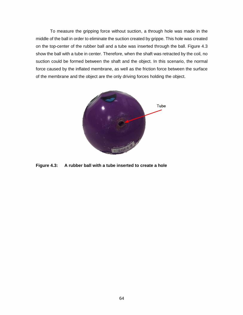
64
To measure the gripping force without suction, a through hole was made in the
middle of the ball in order to eliminate the suction created by grippe. This hole was created
on the top-center of the rubber ball and a tube was inserted through the ball. Figure 4.3
show the ball with a tube in center. Therefore, when the shaft was retracted by the coil, no
suction could be formed between the shaft and the object. In this scenario, the normal
force caused by the inflated membrane, as well as the friction force between the surface
of the membrane and the object are the only driving forces holding the object.
Figure 4.3: A rubber ball with a tube inserted to create a hole

65
Figure 4.4 demonstrates how the applied current impacts the gripping force for
three different currents (2.5 A, 1.8 A, and 0.87 A). The force was measured ten times for
each current. The mean-peak force was then calculated for each current.
Figure 4.4: Force measurement results
The input power can be calculated from the set voltage, and the drawn current.
Figure 4.5 shows how the gripping force changes according to the input power.
Figure 4.5: Gripping Force VS Gripper's input peak power
0
10
20
30
40
50
60
0 20 40 60 80 100
Gri
pp
ing
Forc
e (N
)
Stage 2 Peak input Power (W)

66
4.3. Actuation Speed
One of the biggest advantages of the magnetic gripper is the use of a coil as an
actuator. The gripper’s magnetic shaft and the coil work as a solenoid for actuating the
shaft and gripping objects, enabling very high actuation speeds. When 2.5 A current was
supplied to the coil, the corresponding actuation speed was measured at 0.88 m/s. Figure
4.6 shows how the actuation speed of the gripper changes with the input power. To be
consistent with our previous analysis (Section 4.2), the actuation speed is shown as a
function of the peak power of the gripper. The higher the input power, the higher the
actuation speed would be. Shaft movement of the gripper was recorded using an Iphone
X camera at 240 frames per second, and shaft’s speed was calculated based on the
traveled distance over each time segment.
Figure 4.6: Gripper actuation speed vs input power
4.4. Picking up Objects with Different Shapes and Weights
The gripper was tested with various known objects to check its ability to pick up
different objects with varying shapes and weights. Figure 4.7 shows an example set of
objects picked up by the gripper in a series tests using a KUKA arm. Due to its simple
design and mechanism, the gripper has the potential to be rescaled according to the task
at hand to be able to grip a wide variety of objects in size, geometry, and texture.
As shown in Figure 4.7, the developed prototype here can still pick up wide range
of objects without requiring rescaling. This includes objects with different surface finishes
0
0.1
0.2
0.3
0.4
0.5
0.6
0.7
0.8
0.9
1
90.78 43.98 11.22
Act
uat
ion
Sp
eed
(m
/s)
Input Power (W)

67
like a flat smooth surface (Figure 4.7-D), a relatively rough surface (Figure 4.7-O), light
and delicate objects (Figure 4.7-A and Figure 4.7-H), as well as much heavier ones.
Some examples of these objects include an apple in different orientations (Figure
4.7-A, and Figure 4.7-B), a 796 mL tomato paste steel can (Figure 4.7-C), an acrylic
display riser with a flat smooth surface (Figure 4.7-D), a box of Coke soda cans weighting
about 2.95 Kg measuring 23 cm x 14 cm x 12 cm (8 cans of 355 mL, Figure 4.7-E), a 2 L
Pepsi bottle (Figure 4.7-F), a honey dew about 2.5 Kg (Figure 4.7-G), a light bulb (Figure
4.7-H), a 591 mL VitaminWater in different orientations (Figure 4.7-I, and Figure 4.7-J), a
355 mL Red Bull energy drink in different orientations (Figure 4.7-K, and Figure 4.7-L), a
tomato in different orientations (Figure 4.7-M, and Figure 4.7-N), a football with a rough
surface (Figure 4.7-O), a 0.74 Kg mixed nut container (Figure 4.7-P), a watermelon (Figure
4.7-Q), a ream of letter size paper (Figure 4.7-R), and an oversized drone box about 1.9
Kg and measuring 58 cm x 57 cm x 14 cm (Figure 4.7-S).

68
Figure 4.7: Picking up objects with various shapes and weights.

69
Figure 4.8 shows more complicated gripping scenarios. First and third columns of
Figure 4.8 show the objects from the perspective of the gripper, where it is supposed to
be in contact with gripper’s membrane.
Figure 4.8-A shows a bell pepper from the side where it has the most unevenness
in shape. Figure 4.8-B is a grapefruit which has a porous surface and can be slightly damp
due to the fruit’s nature. Figure 4.8-C is a lime which has similar surface to the grapefruit.
Figure 4.8-D is a bag of 66 g chips. Figure 4.8-E is a pair of jeans wrapped manually in a
really thin nylon, showing how the gripper can lift this by just grabbing the loose nylon.
Figure 4.8-F is a tennis ball which is porous, showing the gripping action without any
suction. Figure 4.8-G is an empty box that is relatively large, showing how the gripper can
pick even when it is not picking an item from the center point. Figure 4.8-H is a full fire
extinguisher that is about 3.5 kg.
Figure 4.8: Gripping various objects and a picture of their contact point with the gripper

70
Chapter 5. Conclusion
This chapter summarizes the thesis work and reviews the key contributions of this
work.
Objective 1: The first objective of this work was the design and fabrication of a
novel robotic gripper that could be implemented in a wide range of industrial applications.
A micro-controller drives the gripper, allowing for a simple control mechanism of the
gripper both in hardware and software. The gripper’s body is fixed to a robotic arm’s end
effector and the shaft assembly is the only movable part in the design of this gripper, hence
mechanical wear and tear of the gripper is minimal.
The gripper’s final dimensions are 11.5 cm in diameter and 15.5 cm in length (1582
cm2) when the shaft is fully extended (considering the maximum volume it can occupy as
a solid cylinder in space). This confirms that the gripper is compact and has about the
same dimensions compared to other commercially available grippers for collaborative
robots.
The gripper’s chamber is sealed using a silicone soft membrane. This membrane
is the contact point of the gripper with the object being picked allowing grasping of objects
with different shapes and even very delicate objects like fruits or a light bulb possible
without any excessive pressure that could damage the object. Another advantage of the
silicone membrane is that it can conform to the surface of the object at its contact point.
As the gripper gets closer to the object, the membrane inflates around the object, allowing
gripping of the target object without the need for accurate alignment of the end effector
with the object’s orientation.
Unlike most robotic grippers such as anthropomorphic grippers or the ones with
suction cups, the proposed gripper can pick target objects from clustered environments.
The soft membrane can come in contact with the target surface from most orientations
and still form strong suction.

71
Objective 2: To address the second objective of this work an actuator was
designed for this gripper without requiring any additional equipment (e.g. pressure air line)
for functionality making it a self-contained gripper.
The gripper’s actuation mechanism consists of a solenoid actuator with a magnetic
shaft, allowing for fast gripping action. The mean actuation speed of the gripper was
measured at 0.88 m/s, which is much higher than 0.2 m/s proposed in the objective. In
addition, the magnetic shaft increases the solenoid actuator’s force and makes the shaft
bidirectional in contrast to other solenoid actuators with an iron shaft.
Another advantage of this gripper is that peak power can be adjusted depending
on intended objects being picked. The griping force consists of friction forces due to the
normal force between the surface of the silicone membrane and the object, as well as the
suction force of the gripper.
To test and evaluate the effectiveness of the designed gripper in relevant industrial
applications, a series of pick-and-place experiments were conducted with the gripper
mounted on a KUKA robotic arm. The gripper was successfully tested on a variety of
everyday objects from simple ones such fruits, snacks, clothing, and health essentials to
more complicated objects like a heavy fire extinguisher about 3.5 Kg, a cloth in a very
loose plastic bag, and an oversized box (Section 4.4).

72
References
[1] C. Ray, F. Mondada, and R. Siegwart, “What do people expect from robots?,” in
2008 IEEE/RSJ International Conference on Intelligent Robots and Systems,
2008, pp. 3816–3821.
[2] R. Pfeifer and M. Lungarella, “The Challenges Ahead for Bio-Inspired ‘Soft’
Robotics,” Commun. ACM, vol. 55, no. 11, pp. 76–87, 2012.
[3] B. Matthias, S. Kock, H. Jerregard, M. Kallman, and I. Lundberg, “Safety of
collaborative industrial robots: Certification possibilities for a collaborative
assembly robot concept,” in IEEE International Symposium on Assembly and
Manufacturing, 2011, pp. 1–6.
[4] J. Kruger, T. K. Lien, and A. Verl, “Cooperation of human and machines in
assembly lines,” CIRP Ann., vol. 58, no. 2, pp. 628–646, Jan. 2009.
[5] G. J. Monkman, S. Hesse, R. Steinmann, and H. Schunk, Robot grippers.
Germany: John Wiley & Sons: Weinheim, 2007.
[6] A. Bertelsen, J. Melo, E. Sánchez, and D. Borro, “A review of surgical robots for
spinal interventions,” Int. J. Med. Robot. Comput. Assist. Surg., vol. 9, no. 4, pp.
407–422, Dec. 2013.
[7] K. Tai et al., “State of the Art Robotic Grippers and Applications,” Robotics, vol. 5,
no. 2, p. 11, Jun. 2016.
[8] A. Pattersson, T. Ohlsson, S. Davis, J. O. Gray, and T. J. Dodd, “A hygienically
designed force gripper for flexible handling of variable and easily damaged natural
food products,” Innov. Food Sci. Emerg. Technol., vol. 12, no. 3, pp. 344–351, Jul.
2011.
[9] G. Fantoni et al., “Grasping devices and methods in automated production
processes,” CIRP Ann., vol. 63, no. 2, pp. 679–701, Jan. 2014.
[10] F. Biganzoli and G. Fantonib, “A self-centering electrostatic microgripper,” J.
Manuf. Syst., vol. 27, no. 3, pp. 136–144, Jul. 2008.
[11] S. Tiefeng, D. Mingyu, B. Guanjun, Z. Libin, and Y. Qinghua, “Fruit harvesting
continuum manipulator inspired by elephant trunk,” Int. J. Agric. Biol. Eng., vol. 8,
no. 1, pp. 57–63, Feb. 2015.
[12] K. Sangbae, C. Laschi, and B. Trimmer, “Soft robotics: a bioinspired evolution in
robotics,” Trends Biotechnol., vol. 31, no. 5, pp. 287–294, May 2013.
[13] J. Amend, E. Brown, N. Rodenberg, H. Jaeger, and H. Lispn, “A positive pressure

73
universal gripper based on the jamming of granular material,” IEEE Trans. Robot.,
vol. 28, no. 2, pp. 341–350, 2012.
[14] N. G. Cheng et al., “Design and Analysis of a Robust, Low-cost, Highly Articulated
manipulator enabled by jamming of granular media,” in 2012 IEEE International
Conference on Robotics and Automation, 2012, pp. 4328–4333.
[15] C. Laschi, M. Cianchetti, B. Mazzolai, L. Margheri, M. Follador, and P. Dario, “Soft
Robot Arm Inspired by the Octopus,” Adv. Robot., vol. 26, no. 7, pp. 709–727,
Jan. 2012.
[16] “Products | OnRobot.” [Online]. Available: https://onrobot.com/en/products.
[Accessed: 10-Dec-2019].
[17] H. D. Bos and I. Wassink, “Evolution of Robotic Hands,” Univ. Twente, 2010.
[18] D. Alba, M. Armada, and R. Ponticelli, “An Introductory Revision to Humanoid
Robot Hands,” in Climbing and Walking Robots, Berlin, Heidelberg: Springer
Berlin Heidelberg, 2005, pp. 701–712.
[19] J. Krahn, F. Fabbro, and C. Menon, “A soft-touch gripper for grasping delicate
objects,” IEEE/ASME Trans. Mechatronics, vol. 22, no. 3, pp. 1276–1286, 2017.
[20] M. Grebenstein, M. Chalon, and W. Friedl, “The hand of the DLR hand arm
system: Designed for interaction,” Int. J. Rob. Res., vol. 31, no. 13, pp. 1531–
1555, 2012.
[21] M. A. Roa and R. Suárez, “Grasp quality measures: review and performance,”
Auton. Robots, vol. 38, no. 1, pp. 65–88, Jan. 2015.
[22] R. Boughdiri, H. Nasser, H. Bezine, N. Sirdi, A. Alimi, and A. Naakmane,
“Dynamic modeling and control of a multi-fingered robot hand for grasping task,”
Procedia Eng., vol. 41, pp. 923–931, 2012.
[23] J. Kerr and B. Roth, “Analysis of Multifingered Hands,” Int. J. Rob. Res., vol. 4, no.
4, pp. 3–17, Jan. 1986.
[24] H. Choi and M. Koc, “Design and feasibility tests of a flexible gripper based on
inflatable rubber pockets,” Int. J. Mach. Tools Manuf., vol. 46, no. 12–13, pp.
1350–1361, 2006.
[25] T. Laliberté, L. Birglen, and C. M. Gosselin, “Underactuation in robotic grasping
hands,” 2002.
[26] S. Montambault and C. M. Gosselin, “Analysis of underactuated mechanical
grippers,” J. Mech. Des. Trans. ASME, vol. 123, no. 3, pp. 367–374, 2001.
[27] J. D. Crisman, C. Kanojia, and I. Zeid, “Graspar: A flexible, easily controllable

74
robotic hand,” IEEE Robot. Autom. Mag., vol. 3, no. 2, pp. 32–38, Jun. 1996.
[28] R. M. Crowder and D. R. Whatley, “Robotic gripping device having linkage
actuated finger sections,” US4834443A, 1986.
[29] S. J. Bartholet, “Reconfigurable end effector,” US5108140A, 1990.
[30] T. Nishimura, K. Mizushima, Y. Suzuki, T. Tsuji, and T. Watanabe, “Variable-
Grasping-Mode Underactuated Soft Gripper with Environmental Contact-Based
Operation,” IEEE Robot. Autom. Lett., vol. 2, no. 2, pp. 1164–1171, Apr. 2017.
[31] L. U. Odhner et al., “A compliant, underactuated hand for robust manipulation,”
Int. J. Rob. Res., vol. 33, no. 5, pp. 736–752, Apr. 2014.
[32] F. Ilievski, A. D. Mazzeo, R. F. Shepherd, X. Chen, and G. M. Whitesides, “Soft
robotics for chemists,” Angew. Chemie - Int. Ed., vol. 50, no. 8, pp. 1890–1895,
2011.
[33] R. Deimel and O. Brock, “A compliant hand based on a novel pneumatic
actuator,” IEEE Int. Conf. Robot. Autom., 2013.
[34] M. E. Giannaccini et al., “A variable compliance, soft gripper,” Auton. Robots, vol.
36, no. 1–2, pp. 93–107, Jan. 2014.
[35] R. Kolluru, K. P. Valavanis, and T. M. Hebert, “Modeling, analysis, and
performance evaluation of a robotic gripper system for limp material handling,”
IEEE Trans. Syst., vol. 28, no. 3, pp. 480–486, 1998.
[36] R. Kolluru, K. P. Valavanis, S. S. Smith, and N. Tsourveloudis, “Design
fundamentals of a reconfigurable robotic gripper system,” IEEE Trans. Syst., vol.
30, no. 2, pp. 181–187, 200AD.
[37] J. Shintake, V. Cacucciolo, D. Floreano, and H. Shea, “Soft Robotic Grippers,”
Adv. Mater., vol. 30, no. 29, pp. 1–33, 2018.
[38] E. Brown et al., “Universal robotic gripper based on the jamming of granular
material,” Proc. Natl. Acad. Sci., vol. 107, no. 44, pp. 18809–18814, Nov. 2010.
[39] W. Zesch, M. Brunner, and A. Weber, “Vacuum tool for handling microobjects with
a NanoRobot,” Proc. Int. Conf. Robot. Autom., no. April, pp. 1761–1766, 1997.
[40] F. Maghooa, A. Stilli, Y. Noh, K. Althoefer, and H. A. Wurdemann, “Tendon and
pressure actuation for a bio-inspired manipulator based on an antagonistic
principle,” in Proceedings - IEEE International Conference on Robotics and
Automation, 2015, vol. 2015-June, no. June, pp. 2556–2561.
[41] A. Pettersson, S. Davis, J. O. Gray, T. J. Dodd, and T. Ohlsson, “Design of a
magnetorheological robot gripper for handling of delicate food products with

75
varying shapes,” J. Food Eng., vol. 98, no. 3, pp. 332–338, Jun. 2010.
[42] F. Erzincanli and J. M. Sharp, “Meeting the need for robotic handling of food
products,” Food Control, vol. 8, no. 4, pp. 185–190, 1997.
[43] S. Davis, J. O. Gray, and D. G. Caldwell, “An end effector based on the Bernoulli
principle for handling sliced fruit and vegetables,” Robot. Comput. Integr. Manuf.,
vol. 24, no. 2, pp. 249–257, Apr. 2008.
[44] A. Pettersson, T. Ohlsson, S. Davis, J. O. Gray, and T. J. Dodd, “A hygienically
designed force gripper for flexible handling of variable and easily damaged natural
food products,” Innov. Food Sci. Emerg. Technol., vol. 12, no. 3, pp. 344–351, Jul.
2011.
[45] Z. Wang, Y. Torigoe, and S. Hirai, “A Prestressed Soft Gripper: Design, Modeling,
Fabrication, and Tests for Food Handling,” IEEE Robot. Autom. Lett., vol. 2, no. 4,
pp. 1909–1916, Oct. 2017.
[46] T. Tarvainen and W. Yu, “Pneumatic Multi-Pocket Elastomer Actuators for
Metacarpophalangeal Joint Flexion and Abduction-Adduction,” Actuators, vol. 6,
no. 3, p. 27, 2017.
[47] K. Suzumori, S. Iikura, and H. Tanaka, “Development of flexible microactuator and
its applications to robotic mechanisms,” IEEE Int. Conf. Robot. Autom., 1991.
[48] K. Suzumori, S. Iikura, and H. Tanaka, “Applying a flexible microactuator to
robotic mechanisms,” IEEE Control Syst. Mag., vol. 12, no. 1, p. 21.27, 1992.
[49] S. Terryn, J. Brancart, D. Lefeber, G. Van Assche, and B. Vanderborght, “Self-
healing soft pneumatic robots,” Sci. Robot., vol. 2, no. 9, p. eaan4268, 2017.
[50] N. America et al., “High-Speed Electrically Actuated Elastomers with Strain
Greater Than 100 %,” vol. 287, no. February, pp. 836–840, 2000.
[51] S. Song, C. Majidi, and M. Sitti, “GeckoGripper: A soft, inflatable robotic gripper
using gecko-inspired elastomer micro-fiber adhesives,” IEEE Int. Conf. Intell.
Robot. Syst., no. Iros, pp. 4624–4629, 2014.
[52] G. Monkman, “Electroadhesive microgrippers,” Ind. Rob., vol. 30, no. 4, pp. 326–
330, 2003.
[53] J. Shintake, S. Rosset, B. Schubert, D. Floreano, and H. Shea, “Versatile Soft
Grippers with Intrinsic Electroadhesion Based on Multifunctional Polymer
Actuators,” Adv. Mater., vol. 28, no. 2, pp. 231–238, 2016.
[54] E. W. Schaler, D. Ruffatto, P. Glick, V. White, and A. Parness, “An electrostatic
gripper for flexible objects,” IEEE Int. Conf. Intell. Robot. Syst., vol. 2017-Septe,

76
pp. 1172–1179, 2017.
[55] M. Calisti et al., “An octopus-bioinspired solution to movement and manipulation
for soft robots,” Bioinspiration and Biomimetics, vol. 6, no. 3, 2011.
[56] D. Rus and M. T. Tolley, “Design, fabrication and control of soft robots,” Nature
research journal, vol. 521, no. 7553. Nature Publishing Group, pp. 467–475, 27-
May-2015.
[57] M. Manti, T. Hassan, G. Passetti, N. D’Elia, M. Cianchetti, and C. Laschi, “An
under-actuated and adaptable soft robotic gripper,” in Biomimetic and Biohybrid
Systems. Living Machines 2015, 2015, vol. 9222, pp. 64–74.
[58] R. Bogue, “Flexible and soft robotic grippers: The key to new markets?,” Ind.
Rob., vol. 43, no. 3, pp. 258–263, May 2016.
[59] “Soft Robotics.” [Online]. Available: https://www.softroboticsinc.com/. [Accessed:
05-Dec-2019].
[60] “FlexShapeGripper | Festo Corporate.” [Online]. Available:
https://www.festo.com/group/en/cms/10217.htm. [Accessed: 05-Dec-2019].
[61] “Suction cups, Vacuum cups, Vacuum pads.” [Online]. Available:
http://www.vacmotion.com/Suction Cups.htm. [Accessed: 20-Jun-2019].
[62] D. Rus and M. T. Tolley, “Design, fabrication and control of soft robots,” Nature,
vol. 521, no. 7553, pp. 467–475, May 2015.
[63] B. H. Shin, K. M. Lee, and S. Y. Lee, “A Miniaturized Tadpole Robot Using an
Electromagnetic Oscillatory Actuator,” J. Bionic Eng., vol. 12, no. 1, pp. 29–36,
2015.
[64] D. Ebihara and M. Watada, “Development of A Single-winding Linear Oscillatory
Actuator,” IEEE Trans. Magn., vol. 28, no. 5, pp. 3030–3032, 1992.
[65] B. Lequesne, “Fast-Acting Long-Stroke Bistable Solenoids with Moving
Permanent Magnets,” IEEE Trans. Ind. Appl., vol. 26, no. 3, pp. 401–407, 1990.
[66] N. Borcea, A. D. Ionescu, and M. S. Barbulescu, “Electromagnetic gripper
assembly,” US4667998A, 1987.
[67] S. R. Covert, J. P. Moore, and J. M. Rhoades, “Tube gripper device,”
US5775755A, 1997.
[68] J. W. Geary and P. E. McCormic, “Solenoid gripper,” US8186733B2, 2012.
[69] J. Kim and J. Chang, “A new electromagnetic linear actuator for quick latching,” in
IEEE Transactions on Magnetics, 2007, vol. 43, no. 4, pp. 1849–1852.
[70] R. B. Van Varseveld and G. M. Bone, “Accurate position control of a pneumatic

77
actuator using on/off solenoid valves,” IEEE/ASME Trans. Mechatronics, vol. 2,
no. 3, pp. 195–204, 1997.
[71] C. Song and S. Lee, “Design of a solenoid actuator with a magnetic plunger for
miniaturized segment robots,” Appl. Sci. J., vol. 5, no. 3, pp. 595–607, 2015.
[72] S. Bammesberger et al., “A Low-Cost, Normally Closed, Solenoid Valve for Non-
Contact Dispensing in the Sub-µL Range,” Micromachines, vol. 4, no. 1, pp. 9–21,
Feb. 2013.
[73] S. Kartmann, P. Koltay, R. Zengerle, and A. Ernst, “A Disposable Dispensing
Valve for Non-Contact Microliter Applications in a 96-Well Plate Format,”
Micromachines, vol. 6, no. 4, pp. 423–436, Apr. 2015.
[74] “Standard Stock Coils | Electromagnetic Solenoid Coils | APW Company.”
[Online]. Available: https://apwelectromagnets.com/standard-coils/. [Accessed:
05-Jun-2018].
[75] “Industrial Robot Finder Tool | FANUC America.” [Online]. Available:
https://www.fanucamerica.com/products/robots/robot-finder-tool. [Accessed: 03-
Jun-2018].
[76] “Silicone Rubber - Platinum Cure from Smooth-On, Inc.” [Online]. Available:
https://www.smooth-on.com/category/platinum-silicone/. [Accessed: 10-Jul-2019].
[77] “High Temp Resin 1 L | Formlabs.” [Online]. Available:
https://formlabs.com/store/form-2/materials/high-temp-resin/. [Accessed: 01-Aug-
2019].
[78] “LBR iiwa | KUKA AG.” [Online]. Available: https://www.kuka.com/en-
ca/products/robotics-systems/industrial-robots/lbr-iiwa. [Accessed: 17-Jun-2019].
[79] “American Wire Gauge Chart and AWG Electrical Current Load Limits table with
ampacities, wire sizes, skin depth frequencies and wire breaking strength.”
[Online]. Available: https://www.powerstream.com/Wire_Size.htm. [Accessed: 26-
Jun-2019].
[80] W. Robertson, B. Cazzolato, and A. Zander, “Axial force between a thick coil and
a cylindrical permanent magnet: Optimizing the geometry of an electromagnetic
actuator,” IEEE Trans. Magn., vol. 48, no. 9, pp. 2479–2487, 2012.
[81] W. Robertson, B. Cazzolato, and A. Zander, “A simplified force equation for
coaxial cylindrical magnets and thin coils,” IEEE Trans. Magn., vol. 47, no. 8, pp.
2045–2049, 2011.
[82] “MAGCODE: models for calculating magnetic fields and interactions_GitHub.”

78
[Online]. Available: https://github.com/wspr/magcode. [Accessed: 23-Jan-2019].
[83] H. M. Pandey, A. Chaudhary, and D. Mehrotra, “A comparative review of
approaches to prevent premature convergence in GA,” Applied Soft Computing
Journal, vol. 24. Elsevier Ltd, pp. 1047–1077, 2014.
[84] H. M. Pandey, M. Rajput, and V. Mishra, “Performance comparison of pattern
search, simulated annealing, genetic algorithm and jaya algorithm,” in Advances
in Intelligent Systems and Computing, 2018, vol. 542, pp. 377–384.
[85] B. Ozpineci, L. M. Tolbert, and J. N. Chiasson, “Harmonic optimization of
multilevel converters using genetic algorithms,” in PESC Record - IEEE Annual
Power Electronics Specialists Conference, 2004, vol. 5, pp. 3911–3916.
[86] A. Dekkers and E. Aarts, “Global optimization and simulated annealing,” Math.
Program., vol. 50, no. 1–3, pp. 367–393, Mar. 1991.
[87] S. A. Kravitz and R. A. Rutenbar, “Placement by Simulated Annealing on a
Multiprocessor,” IEEE Trans. Comput. Des. Integr. Circuits Syst., vol. 6, no. 4, pp.
534–549, 1987.
[88] V. Torczon, “Pattern Search Methods for Nonlinear Optimization,” 1995.
[89] J. W. Chinneck, PRACTICAL OPTIMIZATION: A GENTLE INTRODUCTION.
2015.
[90] K. A. Daltorio, S. Gorb, A. Peressadko, A. D. Horchler, R. E. Ritzmann, and R. D.
Quinn, “A Robot that Climbs Walls using Micro-structured Polymer Feet,” in
Climbing and Walking Robots, Berlin, Heidelberg: Springer Berlin Heidelberg,
2006, pp. 131–138.
[91] O. Unver, “Geckobot : A Gecko Inspired Climbing Robot Using Elastomer
Adhesives,” no. May, pp. 2329–2335, 2006.
[92] D. Santos, S. Kim, M. Spenko, A. Parness, and M. Cutkosky, “Directional
adhesive structures for controlled climbing on smooth vertical surfaces,” Proc. -
IEEE Int. Conf. Robot. Autom., no. April, pp. 1262–1267, 2007.
[93] D. Santos, B. Heyneman, S. Kim, N. Esparza, and M. R. Cutkosky, “Gecko-
inspired climbing behaviors on vertical and overhanging surfaces,” Proc. - IEEE
Int. Conf. Robot. Autom., pp. 1125–1131, 2008.
[94] “Smooth-On Materials Documents.” [Online]. Available: https://www.smooth-
on.com/documents/. [Accessed: 05-Jun-2018].
[95] “Durometer Shore Hardness Scale.” [Online]. Available: https://www.smooth-
on.com/page/durometer-shore-hardness-scale/. [Accessed: 09-Sep-2018].

79
[96] “ATI Industrial Automation: F/T Sensor Mini45.” [Online]. Available:
https://www.ati-ia.com/products/ft/ft_models.aspx?id=Mini45. [Accessed: 06-Aug-
2019].