soft error detection (sed)/correction (sec) usage guide
TRANSCRIPT

Soft Error Detection (SED)/Correction (SEC) Usage Guide for Nexus Platform
Technical Note
FPGA-TN-02076-1.2
June 2021

Soft Error Detection (SED)/Correction (SEC) Usage Guide for Nexus Platform Technical Note
© 2020-2021 Lattice Semiconductor Corp. All Lattice trademarks, registered trademarks, patents, and disclaimers are as listed at www.latticesemi.com/legal. All other brand or product names are trademarks or registered trademarks of their respective holders. The specifications and information herein are subject to change without notice.
2 FPGA-TN-02076-1.2
Disclaimers Lattice makes no warranty, representation, or guarantee regarding the accuracy of information contained in this document or the suitability of its products for any particular purpose. All information herein is provided AS IS and with all faults, and all risk associated with such information is entirely with Buyer. Buyer shall not rely on any data and performance specifications or parameters provided herein. Products sold by Lattice have been subject to limited testing and it is the Buyer's responsibility to independently determine the suitability of any products and to test and verify the same. No Lattice products should be used in conjunction with mission- or safety-critical or any other application in which the failure of Lattice’s product could create a situation where personal injury, death, severe property or environmental damage may occur. The information provided in this document is proprietary to Lattice Semiconductor, and Lattice reserves the right to make any changes to the information in this document or to any products at any time without notice.
Soft Error Detection (SED)/Correction (SEC) Usage Guide for Nexus Platform Technical Note
© 2020-2021 Lattice Semiconductor Corp. All Lattice trademarks, registered trademarks, patents, and disclaimers are as listed at www.latticesemi.com/legal. All other brand or product names are trademarks or registered trademarks of their respective holders. The specifications and information herein are subject to change without notice.
FPGA-TN-02076-1.2 3
Contents Acronyms in This Document ................................................................................................................................................. 5 1. Introduction .................................................................................................................................................................. 6 2. SED Overview ................................................................................................................................................................ 7
2.1. Block Diagram ..................................................................................................................................................... 8 3. Port List ....................................................................................................................................................................... 10 4. Port Descriptions ........................................................................................................................................................ 11
4.1. cfg_clk_i ............................................................................................................................................................ 11 4.2. sedc_mode_i ..................................................................................................................................................... 11 4.3. sedc_start_i ....................................................................................................................................................... 11 4.4. sedc_en_i .......................................................................................................................................................... 11 4.5. sed_en_i ............................................................................................................................................................ 11 4.6. sedc_cof_i ......................................................................................................................................................... 11 4.7. sedc_rst_i .......................................................................................................................................................... 11 4.8. sedc_busy_o ...................................................................................................................................................... 11 4.9. sedc_errc_o ....................................................................................................................................................... 12 4.10. sedc_err_o ........................................................................................................................................................ 12 4.11. sedc_errm_o ..................................................................................................................................................... 12 4.12. sedc_errcrc_o .................................................................................................................................................... 12 4.13. sedc_frm_errloc_o[15:0] .................................................................................................................................. 12 4.14. sedc_dsr_errloc_o[12:0] ................................................................................................................................... 12
5. SED Clock and Reset ................................................................................................................................................... 13 6. SED Flow ..................................................................................................................................................................... 14
6.1. SED Mode .......................................................................................................................................................... 15 6.1.1. Continuous Mode ......................................................................................................................................... 15 6.1.2. One-shot Mode ............................................................................................................................................ 15
6.2. SED Error Handling ............................................................................................................................................ 16 7. SEC Flow...................................................................................................................................................................... 17 8. SED Run Time .............................................................................................................................................................. 18 9. Sample Code ............................................................................................................................................................... 19
9.1. SED Verilog Example ......................................................................................................................................... 19 9.1.1. Verilog Example of SED IP ............................................................................................................................ 19 9.1.2. Verilog SED IP Instantiation .......................................................................................................................... 19
9.2. SED VHDL Example ............................................................................................................................................ 20 9.2.1. VHDL Component Instantation .................................................................................................................... 20 9.2.2. VHDL Instantiation ....................................................................................................................................... 20
10. Soft Error Injection (SEI) ............................................................................................................................................. 21 Technical Support Assistance ............................................................................................................................................. 23 Revision History .................................................................................................................................................................. 24

Soft Error Detection (SED)/Correction (SEC) Usage Guide for Nexus Platform Technical Note
© 2020-2021 Lattice Semiconductor Corp. All Lattice trademarks, registered trademarks, patents, and disclaimers are as listed at www.latticesemi.com/legal. All other brand or product names are trademarks or registered trademarks of their respective holders. The specifications and information herein are subject to change without notice.
4 FPGA-TN-02076-1.2
Figures Figure 2.1. Bitstream Data Structure .................................................................................................................................... 7 Figure 2.2. SED/SEC System Block Diagram .......................................................................................................................... 8 Figure 2.3. SED/SEC Block Diagram ....................................................................................................................................... 9 Figure 5.1. SED CLK/RST ...................................................................................................................................................... 13 Figure 6.1. SED Flow ........................................................................................................................................................... 14 Figure 6.2. SED Continuous Mode ...................................................................................................................................... 15 Figure 6.3. SED One-Shot Mode ......................................................................................................................................... 15 Figure 6.4. SEDC Error Handling Flags (Single Scan Duration Shown) ................................................................................ 16 Figure 7.1. SEC Flow ............................................................................................................................................................ 17 Figure 10.1. SEI Editor ......................................................................................................................................................... 21 Figure 10.2. Device Properties ............................................................................................................................................ 22
Tables Table 3.1. SED Primitive Port Definitions ............................................................................................................................ 10 Table 5.1. SED Internal Oscillator Divider Settings ............................................................................................................. 13

Soft Error Detection (SED)/Correction (SEC) Usage Guide for Nexus Platform Technical Note
© 2020-2021 Lattice Semiconductor Corp. All Lattice trademarks, registered trademarks, patents, and disclaimers are as listed at www.latticesemi.com/legal. All other brand or product names are trademarks or registered trademarks of their respective holders. The specifications and information herein are subject to change without notice.
FPGA-TN-02076-1.2 5
Acronyms in This Document A list of acronyms used in this document.
Acronym Definition
CRC Cyclic Redundancy Check
ECC Error Correcting Code
DRAM Dynamic Random Access Memory
IP Intellectual Property
PLD Programmable Logic Device
SED Soft Error Detection
SEC Soft Error Correction
SEI Soft Error Injection
SRAM Static Random Access Memory

Soft Error Detection (SED)/Correction (SEC) Usage Guide for Nexus Platform Technical Note
© 2020-2021 Lattice Semiconductor Corp. All Lattice trademarks, registered trademarks, patents, and disclaimers are as listed at www.latticesemi.com/legal. All other brand or product names are trademarks or registered trademarks of their respective holders. The specifications and information herein are subject to change without notice.
6 FPGA-TN-02076-1.2
1. Introduction This document describes the hard-logic based SED approach taken by Lattice Semiconductor for the Lattice Nexus™ platform devices, including Crosslink™-NX, Certus™-NX, and CertusPro™-NX families. Once soft error is detected, Lattice provides an easy way to optionally perform the Soft Error Correction (SEC) without disturbing the functionality of the device.
Memory errors can occur when high-energy charged particles alter the stored charge in a memory cell in an electronic circuit. The phenomenon first became an issue in Dynamic Random Access Memory (DRAM), requiring error detection and correction for large memory systems in high-reliability applications. As device geometries continue to shrink, the probability of memory errors in Static Random Access Memory (SRAM) becomes significant for some systems. Designers are using a variety of approaches to minimize the effects of memory errors on system behavior. FPGA devices built on the Lattice Nexus platform, which include CrossLink-NX, Certus-NX, and CertusPro-NX, are unique because the underlying technology used to build them is much more robust and less prone to soft errors.
SRAM-based programmable logic devices (PLDs) store logic configuration data in SRAM cells. As the number and density of SRAM cells in a PLD increase, the probability that a memory error alters the programmed logical behavior of the system increases. A number of traditional approaches are taken to address this issue, but most involve soft Intellectual Property (IP) cores that you instantiate into the logic of your design, utilizing valuable resources and possibly affecting design performance.
The Nexus platform devices have an improved hardware implemented Soft Error Detection (SED) circuit which can be used to detect SRAM errors and allow them to be corrected. There are two layers of SED implemented in these devices that makes them more robust and reliable.

Soft Error Detection (SED)/Correction (SEC) Usage Guide for Nexus Platform Technical Note
© 2020-2021 Lattice Semiconductor Corp. All Lattice trademarks, registered trademarks, patents, and disclaimers are as listed at www.latticesemi.com/legal. All other brand or product names are trademarks or registered trademarks of their respective holders. The specifications and information herein are subject to change without notice.
FPGA-TN-02076-1.2 7
2. SED Overview The SED module in a Nexus platform device is an enhanced version as compared to the SED modules implemented in other Lattice devices. Enhancements include:
Frame by Frame SED check
Single bit and multi-bit error detection
ECC to correct single bit error at the frame level
Programmable SED clock with a wider clock frequency option
The device is based on the Lattice Nexus platform which is developed using FDSOI technology. FDSOI transistors have a less active region, which helps to reduce bit flipping when exposed to alpha and neutron particles.
Some of the key advantages of Nexus platform devices as compared to other devices are:
Improved radiation tolerance due to reduction in critical area separated by a thin-layer of buried oxide (BOX)
100x improvement in soft errors
Due to the above technology, Nexus platform devices have extremely low bit error rate and fit rate. Details about the fit rate calculation can be found in Single Event Upset (SEU) Report for CrossLink-NX (FPGA-TN-02174).
This SED module is part of the Configuration block in the Nexus platform devices. The configuration data is divided into frames so that the FPGA can be programmed as a whole or in precise parts. The SED hardware reads serial data from the FPGA's configuration memory frame-by-frame in the background while the device is in User mode and performs Error Correcting Code (ECC) calculation on every frame of configuration data (see Figure 2.1). Once a single bit error is detected, a Soft Error Upset (SEU) notification is generated and SED resumes operation. When Soft Error Correction (SEC) is enabled, single bit errors are corrected; the corrected value is rewritten to the particular frame using ECC information. If more than one-bit error is detected within one frame of configuration data, an error message is generated. In parallel, cyclic redundancy check (CRC) is calculated for the entire bitstream along with ECC.
After the ECC is calculated on all frames of configuration data, cyclic redundancy check (CRC) is calculated for the entire configuration data (bitstream).
Due to the dynamic contents of memories, the CRC and ECC calculations do not include EBR and Large RAM memory. Dynamic RAM should not be used with SED, otherwise, SED reports failures when normal RAM content changes occur.
Frame N-1Frame N
ECCECC
CRC (End of Bitstream)
FPGA Data/Bitstream
Frame 1Frame 2
ECCECC
Figure 2.1. Bitstream Data Structure
Soft Error Detection (SED)/Correction (SEC) Usage Guide for Nexus Platform Technical Note
© 2020-2021 Lattice Semiconductor Corp. All Lattice trademarks, registered trademarks, patents, and disclaimers are as listed at www.latticesemi.com/legal. All other brand or product names are trademarks or registered trademarks of their respective holders. The specifications and information herein are subject to change without notice.
8 FPGA-TN-02076-1.2
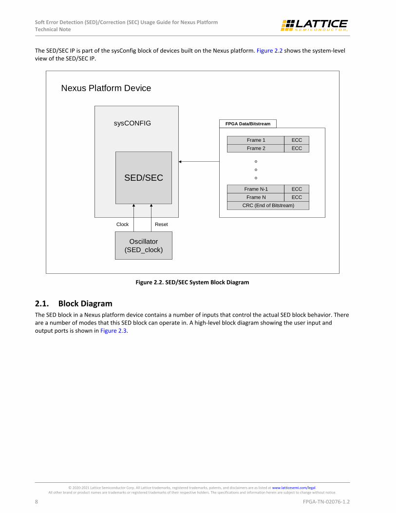
The SED/SEC IP is part of the sysConfig block of devices built on the Nexus platform. Figure 2.2 shows the system-level view of the SED/SEC IP.
SED/SEC
Oscillator
(SED_clock)
Frame N-1
Frame N
ECC
ECC
CRC (End of Bitstream)
FPGA Data/Bitstream
Frame 1
Frame 2
ECC
ECC
sysCONFIG
Nexus Platform Device
Clock Reset
Figure 2.2. SED/SEC System Block Diagram
2.1. Block Diagram The SED block in a Nexus platform device contains a number of inputs that control the actual SED block behavior. There are a number of modes that this SED block can operate in. A high-level block diagram showing the user input and output ports is shown in Figure 2.3.

Soft Error Detection (SED)/Correction (SEC) Usage Guide for Nexus Platform Technical Note
© 2020-2021 Lattice Semiconductor Corp. All Lattice trademarks, registered trademarks, patents, and disclaimers are as listed at www.latticesemi.com/legal. All other brand or product names are trademarks or registered trademarks of their respective holders. The specifications and information herein are subject to change without notice.
FPGA-TN-02076-1.2 9
SED/SEC
cfg_clk_i
sedc_mode_i
sedc_start_i
sedc_en_i
sed_en_i
sedc_cof_i
sed_busy_o
sedc_errc_o
sedc_err_o
sedc_errm_o
sedc_errcrc_o
sedc_frm_errloc_o[15:0]
sedc_bit_errloc_o[12:0] sedc_rst_i
Figure 2.3. SED/SEC Block Diagram

Soft Error Detection (SED)/Correction (SEC) Usage Guide for Nexus Platform Technical Note
© 2020-2021 Lattice Semiconductor Corp. All Lattice trademarks, registered trademarks, patents, and disclaimers are as listed at www.latticesemi.com/legal. All other brand or product names are trademarks or registered trademarks of their respective holders. The specifications and information herein are subject to change without notice.
10 FPGA-TN-02076-1.2
3. Port List To use the SED IP, instantiate the SED IP as well as the Oscillator primitive using the Lattice Radiant™ IP Catalog. Refer to Figure 2.1 that shows how to connect the Oscillator to the SEDC IP. Below is a list of port signals used by the SED IP.
Table 3.1. SED Primitive Port Definitions
Port Name Default Value Active Description
cfg_clk_i 0 Input User input clock for SED. Connect this signal to the OSC module port cfg_clk_o
sedc_mode_i 0 Input SED mode signal
Select between two modes.
sedc_start_i 0 Input SED signal used to start SED
sedc_en_i 0 Input Signal to enable SED
sed_en_i 0 Input Signal to enable Soft Error Correction (SEC)
sedc_cof_i 0 Input SED continue on failure signal
sedc_rst_i 0 Input Reset the SED IP. Connect this signal to the OSC module port sedc_rst_o.
sedc_busy_o 0 Output Signal to indicate SED is in progress
sedc_errc_o 0 Output Indicate Current SED error
sedc_err_o 0 Output 1-bit (correctable) error detected; sticky bit
sedc_errm_o 0 Output Multi-bit error detected within one frame; sticky bit
sedc_errcrc_o 0 Output CRC error for entire bitstream data
sedc_frm_errloc_o[15:0] 0 Output Frame Error location
sedc_dsr_errloc_o[12:0] 0 Output Bit error location within a frame

Soft Error Detection (SED)/Correction (SEC) Usage Guide for Nexus Platform Technical Note
© 2020-2021 Lattice Semiconductor Corp. All Lattice trademarks, registered trademarks, patents, and disclaimers are as listed at www.latticesemi.com/legal. All other brand or product names are trademarks or registered trademarks of their respective holders. The specifications and information herein are subject to change without notice.
FPGA-TN-02076-1.2 11
4. Port Descriptions
4.1. cfg_clk_i The cfg_clk_i is a user-selectable clock signal used to run the SED IP. Table 5.1 defines the various clock divider settings that can be used to define the desired clock speed of the SED block.
4.2. sedc_mode_i sedc_mode_i signal is used to choose the SED mode of operation. There are two SED modes that you can choose from: continuous mode and one-shot mode. For continuous mode, the sedc_mode_i signal is high and once sedc_start_i is HIGH, the SED operation keeps running continuously. For one-shot mode, the sedc_mode_i signal is low and once the SED module detects the low-to-high transition on the sedc_start_i signal, the SED operation runs once. For one-shot mode to operate correctly, you need to make sure sedc_start_i remains asserted until sedc_busy_o is deasserted. In other words, there should not be glitches in the sedc_start_i signal.
4.3. sedc_start_i This sedc_start_i signal is used to start the SED operation. Once the sedc_start_i signal goes high, the SED cycle starts if sedc_en_i is high. In continuous mode, the sedc_start_i signal must remain high for the duration of SED. If sedc_start_i goes low during the SED cycle, the process is terminated and sedc_busy_o is deasserted.
4.4. sedc_en_i The sedc_en_i signal is used to enable SED. SED does not operate, and any in-progress operation aborted, if sedc_en_i is deasserted.
4.5. sed_en_i If sed_en_i is set, the soft error correction is performed immediately as soon as a single correctable error is detected. If this bit is disabled, the correction is not done.
4.6. sedc_cof_i The sedc_cof_i stands for SED_Continue_On_Failure. This signal is used to tell the SED module to run or stop after a non-correctable multiple bit error is detected in a single configuration frame. If sedc_cof_i signal is set to HIGH, the SED operation continues even if non-correctable error is encountered. On the other hand, if sedc_cof_i signal is LOW, the SED operation is terminated as soon as an error is detected. This bit is useful for debugging purposes but not recommended for normal use. Instead, it is recommended to reload the FPGA bitstream (via REFRESH, PROGRAMN assertion, power cycle, or through one of the slave sysConfig ports) in the event a non-correctable error is detected.
4.7. sedc_rst_i The sedc_rst_i signal is used to reset the SED IP. This is an asynchronous reset signal.
4.8. sedc_busy_o The sedc_busy_o signal indicates if SED operation is currently in progress. If the SED is running, the sedc_buys_o is set to HIGH. Once SED operation is complete, this signal goes LOW.

Soft Error Detection (SED)/Correction (SEC) Usage Guide for Nexus Platform Technical Note
© 2020-2021 Lattice Semiconductor Corp. All Lattice trademarks, registered trademarks, patents, and disclaimers are as listed at www.latticesemi.com/legal. All other brand or product names are trademarks or registered trademarks of their respective holders. The specifications and information herein are subject to change without notice.
12 FPGA-TN-02076-1.2
4.9. sedc_errc_o The SED error current flag indicates if a soft error is detected. As soon as an error is detected, this flag goes high indicating it is a current error. This flag is not sticky.
4.10. sedc_err_o The sedc_err_o flag is used to indicate if there is a single bit error in a frame. This flag is sticky. To clear this flag, the SED operation has to be disabled.
This single bit error detected is also correctable. The correction is performed only if the sed_en_i signal is set.
4.11. sedc_errm_o The SED error multiple is used to indicate if non-correctable errors are encountered, such as two or more errors detected in a single frame. Multiple errors are not correctable. This flag is asserted high. This flag is sticky. To clear this flag, disable the SED module or reload the bitstream.
4.12. sedc_errcrc_o The SED error crc indicates if there is a mismatch between calculated CRC of the bitstream as compared to the expected CRC. This error is generated once all the frames of bitstream are read. If there is a single bit error detected, this flag is set. Once the single bit error is corrected, this CRC flag is cleared when SED operation runs for the second time.
4.13. sedc_frm_errloc_o[15:0] The SED frame Error location reports the last location of the frame that errored out. It only provides the frame location for the last one-bit error. This signal reports the 16-bit error location for the frame that is causing error. This signal is only used for information purposes which can be used for further analysis of the SED errors. This field contains invalid data if multiple errors per frame are detected.
Note: This signal is only valid when SEC is enabled (sed_en_i is true).
4.14. sedc_dsr_errloc_o[12:0] The SED bit error location reports the bit position in a particular frame that errored out. This information is useful so that you can perform detailed analysis of the bitstream (on a bit-by-bit basis). This field contains invalid data if multiple errors per frame are detected.
Note: This signal is only valid when SEC is enabled.
Soft Error Detection (SED)/Correction (SEC) Usage Guide for Nexus Platform Technical Note
© 2020-2021 Lattice Semiconductor Corp. All Lattice trademarks, registered trademarks, patents, and disclaimers are as listed at www.latticesemi.com/legal. All other brand or product names are trademarks or registered trademarks of their respective holders. The specifications and information herein are subject to change without notice.
FPGA-TN-02076-1.2 13
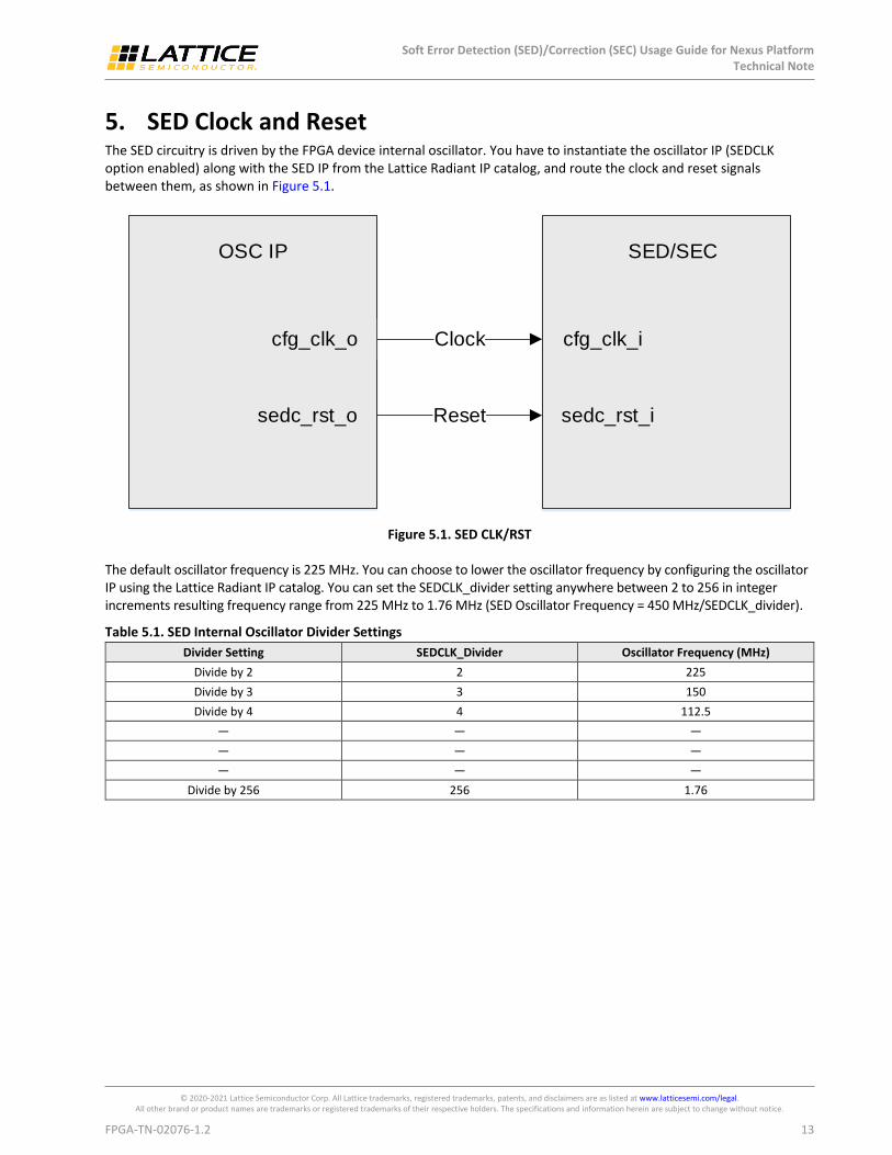
5. SED Clock and Reset The SED circuitry is driven by the FPGA device internal oscillator. You have to instantiate the oscillator IP (SEDCLK option enabled) along with the SED IP from the Lattice Radiant IP catalog, and route the clock and reset signals between them, as shown in Figure 5.1.
Clock
Reset
cfg_clk_o
sedc_rst_o
cfg_clk_i
sedc_rst_i
OSC IP SED/SEC
Figure 5.1. SED CLK/RST
The default oscillator frequency is 225 MHz. You can choose to lower the oscillator frequency by configuring the oscillator IP using the Lattice Radiant IP catalog. You can set the SEDCLK_divider setting anywhere between 2 to 256 in integer increments resulting frequency range from 225 MHz to 1.76 MHz (SED Oscillator Frequency = 450 MHz/SEDCLK_divider).
Table 5.1. SED Internal Oscillator Divider Settings
Divider Setting SEDCLK_Divider Oscillator Frequency (MHz)
Divide by 2 2 225
Divide by 3 3 150
Divide by 4 4 112.5
— — —
— — —
— — —
Divide by 256 256 1.76

Soft Error Detection (SED)/Correction (SEC) Usage Guide for Nexus Platform Technical Note
© 2020-2021 Lattice Semiconductor Corp. All Lattice trademarks, registered trademarks, patents, and disclaimers are as listed at www.latticesemi.com/legal. All other brand or product names are trademarks or registered trademarks of their respective holders. The specifications and information herein are subject to change without notice.
14 FPGA-TN-02076-1.2
6. SED Flow This section describes the SED flow. The SED flow is executed once VCC reaches the data sheet VCC minimum recommended level and sedc_en_i and sedc_start_i are asserted.
Devices built on the Nexus platform have an advanced SED flow with two levels of SED checks. In the first level of SED check, the bitstream is read one frame at a time and the SED check is performed on a frame-by-frame basis. After all frames of the device bitstream are read, the SED module checks for CRC of the entire bitstream, second level SED, to check for the bitstream integrity giving the device improved SED performance. Figure 6.1 shows the SED flow in Nexus platform devices.
Verify data frame
SED error ? No
Yes
Is sed_en_i
set?
Enable SEDSet sedc_en_i
Set sedc_start_i
Read data frame
Last Frame?
No
Yes
No
Is sedc_cof_iset?
Yes
Non-correctable error
No
Perform full bitstream CRC check
Yes
Report error location andPerform SEC
(see Figure 7.1 for details)
Yes
SED Mode?Continuous
Stop SED
One-shot
Figure 6.1. SED Flow

Soft Error Detection (SED)/Correction (SEC) Usage Guide for Nexus Platform Technical Note
© 2020-2021 Lattice Semiconductor Corp. All Lattice trademarks, registered trademarks, patents, and disclaimers are as listed at www.latticesemi.com/legal. All other brand or product names are trademarks or registered trademarks of their respective holders. The specifications and information herein are subject to change without notice.
FPGA-TN-02076-1.2 15
6.1. SED Mode Devices built on the Nexus platform support two different SED modes. This provides you the flexibility to run the SED. The first mode is the continuous mode in which the SED runs continuously. The other mode is one-shot mode in which SED runs once for each assertion of sedc_start_i signal.
6.1.1. Continuous Mode
As the name suggests, in continuous mode, the SED runs continuously as long as the sedc_start_i signal is high.
1. Once the SED is enabled, it starts reading bitstream data frame by frame and verifies if the data is read correctly from configuration SRAM. The sedc_busy_o signal is HIGH as long as SED is running.
2. Once SED finishes checking, the sedc_busy_o goes LOW (once the SED cycles through for the first time).
3. The SED cycles through for the second time as long as sedc_start_i is HIGH since the operation is in Continuous Mode.
Once sedc_mode_i is set to 1 and sedc_start_i is always HIGH, the SED operation runs continuously, as shown in Figure 6.2.
sedc_mode_i
sedc_start_i
sedc_busy_o
Figure 6.2. SED Continuous Mode
6.1.2. One-shot Mode
In this mode, the SED runs once for each assertion of sedc_start_i signal.
1. For One-shot Mode, the sedc_start_i signal must have a LOW to HIGH transition to start the SED operation.
2. The SED starts reading bitstream data frame by frame and verifies if the data is read correctly from configuration SRAM. The sedc_busy_o signal is HIGH as long as SED is running.
3. The SED finishes checking. The SED error flags are updated and the sedc_busy_o flag goes LOW. Another SED cycle is started by making a LOW to HIGH transition on the sedc_start_i signal.
Note: If there is any error, disable the sedc_en_i signal to reset all error flags.
In this mode, the sedc_mode_i signal is set to zero. As soon as there is a low to high transition on the sedc_start_i signal, the SED operation starts. The SED operation is run once for each assertion of sedc_start_i signal and when done, this sedc_busy_o goes LOW, as shown in Figure 6.3.
sedc_mode_i
sedc_start_i
sedc_busy_o
Figure 6.3. SED One-Shot Mode
The preferred action to take when an error is detected is to reconfigure the PLD. Reconfiguration can be accomplished by driving the PROGRAMN pin low. This can be done by externally connecting a GPIO pin to PROGRAMN.

Soft Error Detection (SED)/Correction (SEC) Usage Guide for Nexus Platform Technical Note
© 2020-2021 Lattice Semiconductor Corp. All Lattice trademarks, registered trademarks, patents, and disclaimers are as listed at www.latticesemi.com/legal. All other brand or product names are trademarks or registered trademarks of their respective holders. The specifications and information herein are subject to change without notice.
16 FPGA-TN-02076-1.2
6.2. SED Error Handling The diagram below shows the different types of errors reported by the SED module in Nexus platform devices. The sedc_errc_o signal flags as soon as there is an error. The sedc_err_o, sedc_errm_o, and sedc_errcrc_o are sticky flags and the SED module had to be restarted to reset these error flags as shown in Figure 6.4.
sedc_busy_o
sedc_errc_o
sedc_errm_o
sedc_errcrc_o
sedc_err_o
No error
Single error
No error
Multi-error
No error
sedc_cof_i = set
sedc_cof_i = set
No error
Frame n-1
Framen
Frame n+1
Framen+2
Framen+3
Last Frame
... ...
Figure 6.4. SEDC Error Handling Flags (Single Scan Duration Shown)
Note: In Figure 6.4, sedc_busy_o deasserts during operation briefly, as shown, while the block is performing error correction. Soft Error Correction only occurs if sed_en_i (soft error correction enable) is set. If sed_en_i is not set, sedc_busy_o remains asserted high until all frames are checked, regardless of error state.

Soft Error Detection (SED)/Correction (SEC) Usage Guide for Nexus Platform Technical Note
© 2020-2021 Lattice Semiconductor Corp. All Lattice trademarks, registered trademarks, patents, and disclaimers are as listed at www.latticesemi.com/legal. All other brand or product names are trademarks or registered trademarks of their respective holders. The specifications and information herein are subject to change without notice.
FPGA-TN-02076-1.2 17
7. SEC Flow Devices built on the Nexus platform support real time Soft Error Correction (SEC) feature in which a single bit error can be corrected using ECC at the frame level. Once the SEC is enabled, the SED/SEC module reports the error location, providing details about the error frame and the exact location of a single bit error in that frame. Figure 7.1 shows the SEC flow in Nexus platform devices.
Verify data frame
SED error ? No
Is sed_en_i
set?
Yes
Enable SEDSet sedc_en_i
Set sedc_start_i
Read data frame
Last Frame?
No
Report Error Location
Perform SEC
Is data frame written
correctly?
No
Yes
Is sedc_cof_i set?
No
Perform full bitstream CRC check
Yes
Yes
Single bit error Multi bit error
SED Mode?
ContinuousOne-shot
Stop SED
Non-correctable error
Figure 7.1. SEC Flow

Soft Error Detection (SED)/Correction (SEC) Usage Guide for Nexus Platform Technical Note
© 2020-2021 Lattice Semiconductor Corp. All Lattice trademarks, registered trademarks, patents, and disclaimers are as listed at www.latticesemi.com/legal. All other brand or product names are trademarks or registered trademarks of their respective holders. The specifications and information herein are subject to change without notice.
18 FPGA-TN-02076-1.2
8. SED Run Time In the Nexus platform devices, the amount of time needed to perform a SED check depends on the density of the device, frequency of the SED clock driver signal and the number of shift lanes used to shift data into the device. There is also some overhead time for calculation, but it is fairly short in comparison. An approximation of the SED run time can be found by using the following formula:
SED run time (ms) = (Total no of frames × (bytes per frame + overhead)) / SED clock (MHz)
For example, in LIFCL-40, the run time for SED clock running at 150 MHz is:
Total no. of frame = 9172
Bytes per frame = 85
Overhead bytes = 5
SED Run time = (9172 × (85 + 5) ) / 150 MHz = (9172 × 90) / 150 MHz = 5.5ms
Soft Error Detection (SED)/Correction (SEC) Usage Guide for Nexus Platform Technical Note
© 2020-2021 Lattice Semiconductor Corp. All Lattice trademarks, registered trademarks, patents, and disclaimers are as listed at www.latticesemi.com/legal. All other brand or product names are trademarks or registered trademarks of their respective holders. The specifications and information herein are subject to change without notice.
FPGA-TN-02076-1.2 19
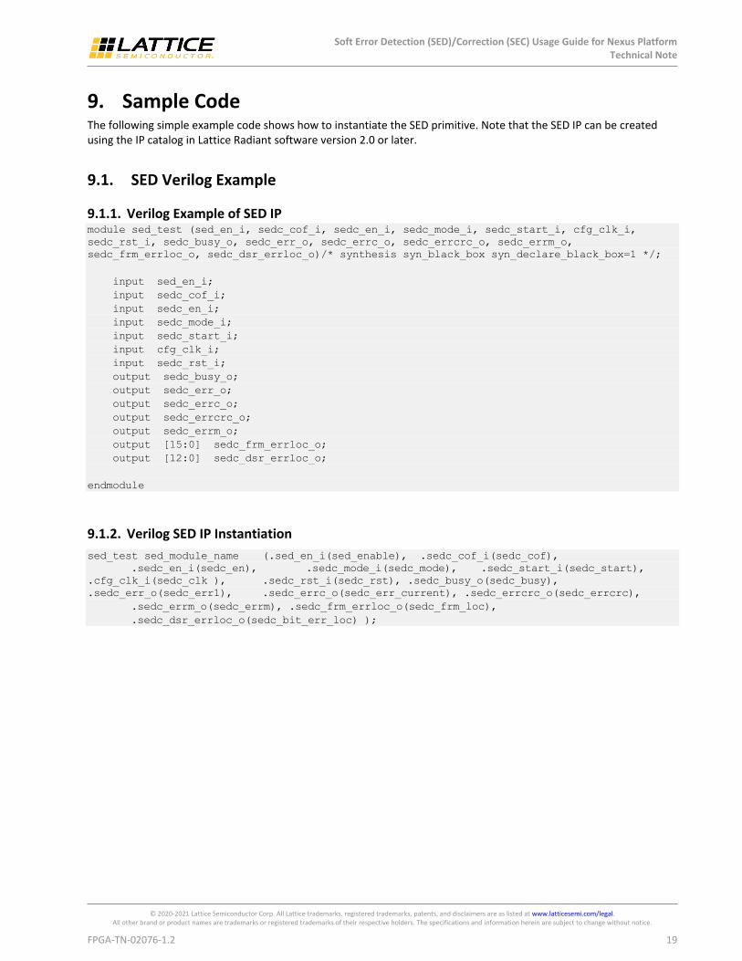
9. Sample Code The following simple example code shows how to instantiate the SED primitive. Note that the SED IP can be created using the IP catalog in Lattice Radiant software version 2.0 or later.
9.1. SED Verilog Example
9.1.1. Verilog Example of SED IP module sed_test (sed_en_i, sedc_cof_i, sedc_en_i, sedc_mode_i, sedc_start_i, cfg_clk_i,
sedc_rst_i, sedc_busy_o, sedc_err_o, sedc_errc_o, sedc_errcrc_o, sedc_errm_o,
sedc_frm_errloc_o, sedc_dsr_errloc_o)/* synthesis syn_black_box syn_declare_black_box=1 */;
input sed_en_i;
input sedc_cof_i;
input sedc_en_i;
input sedc_mode_i;
input sedc_start_i;
input cfg_clk_i;
input sedc_rst_i;
output sedc_busy_o;
output sedc_err_o;
output sedc_errc_o;
output sedc_errcrc_o;
output sedc_errm_o;
output [15:0] sedc_frm_errloc_o;
output [12:0] sedc_dsr_errloc_o;
endmodule
9.1.2. Verilog SED IP Instantiation
sed_test sed_module_name (.sed_en_i(sed_enable), .sedc_cof_i(sedc_cof),
.sedc_en_i(sedc_en), .sedc_mode_i(sedc_mode), .sedc_start_i(sedc_start),
.cfg_clk_i(sedc_clk ), .sedc_rst_i(sedc_rst), .sedc_busy_o(sedc_busy),
.sedc_err_o(sedc_err1), .sedc_errc_o(sedc_err_current), .sedc_errcrc_o(sedc_errcrc),
.sedc_errm_o(sedc_errm), .sedc_frm_errloc_o(sedc_frm_loc),
.sedc_dsr_errloc_o(sedc_bit_err_loc) );

Soft Error Detection (SED)/Correction (SEC) Usage Guide for Nexus Platform Technical Note
© 2020-2021 Lattice Semiconductor Corp. All Lattice trademarks, registered trademarks, patents, and disclaimers are as listed at www.latticesemi.com/legal. All other brand or product names are trademarks or registered trademarks of their respective holders. The specifications and information herein are subject to change without notice.
20 FPGA-TN-02076-1.2
9.2. SED VHDL Example
9.2.1. VHDL Component Instantation
component sed_test is
port(
sed_en_i: in std_logic;
sedc_cof_i: in std_logic;
sedc_en_i: in std_logic;
sedc_mode_i: in std_logic;
sedc_start_i: in std_logic;
cfg_clk_i: in std_logic;
sedc_rst_i: in std_logic;
sedc_busy_o: out std_logic;
sedc_err_o: out std_logic;
sedc_errc_o: out std_logic;
sedc_errcrc_o: out std_logic;
sedc_errm_o: out std_logic;
sedc_frm_errloc_o: out std_logic_vector(15 downto 0);
sedc_dsr_errloc_o: out std_logic_vector(12 downto 0)
);
end component;
9.2.2. VHDL Instantiation
SED_instance: sed_test port map(
sed_en_i=> sed_enable,
sedc_cof_i=> sed_cof,
sedc_en_i=> sedc_en,
sedc_mode_i=> sedc_mode ,
sedc_start_i=> sedc_start,
cfg_clk_i=> sedc_clk,
sedc_rst_i=> sedc_rst,
sedc_busy_o=> sedc_busy,
sedc_err_o=> sedc_err1,
sedc_errc_o=> sedc_err_current,
sedc_errcrc_o=> sedc_errcrc,
sedc_errm_o=> sedc_errm,
sedc_frm_errloc_o=> sedc_frm_loc,
sedc_dsr_errloc_o=> sedc_bit_err_loc );
Soft Error Detection (SED)/Correction (SEC) Usage Guide for Nexus Platform Technical Note
© 2020-2021 Lattice Semiconductor Corp. All Lattice trademarks, registered trademarks, patents, and disclaimers are as listed at www.latticesemi.com/legal. All other brand or product names are trademarks or registered trademarks of their respective holders. The specifications and information herein are subject to change without notice.
FPGA-TN-02076-1.2 21
10. Soft Error Injection (SEI) The Radiant SEI tool offers an easy and economical way to emulate soft error impact to the overall system. This
tool allows you to randomly generate and program one or multiple soft errors into the device in background mode
without disturbing the device function. Radiant SEI tool is supported in Radiant versions 2.1 and higher.
To use the Radiant SEI tool:
1. Select or enable the BACKGROUND_RECONFIG option in the Diamond spreadsheet view when you generate the bitstream.
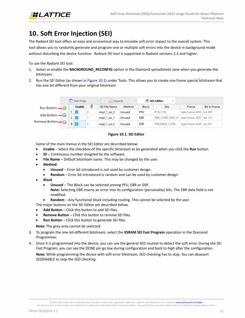
2. Run the SEI Editor (as shown in Figure 10.1) under Tools. This allows you to create one frame special bitstream that has one bit different from your original bitstream
Figure 10.1. SEI Editor
Some of the main menus in the SEI Editor are described below:
Enable – Select the checkbox of the specific bitstream to be generated when you click the Run button.
ID – Continuous number assigned by the software.
File Name – Default bitstream name. This may be changed by the user.
Method
Unused – Error bit introduced is not used by customer design.
Random – Error bit introduced is random and can be used by customer design.
Block
Unused – The Block can be selected among PFU, EBR or DSP. Note: Selecting EBR inserts an error into its configuration (personality) bits. The EBR data field is not modified.
Random – Any functional block including routing. This cannot be selected by the user. The major buttons on the SEI Editor are described below.
Add Button – Click this button to add SEI files.
Remove Button – Click this button to remove SEI files.
Run Button – Click this button to generate SEI files.
Note: The grey area cannot be selected.
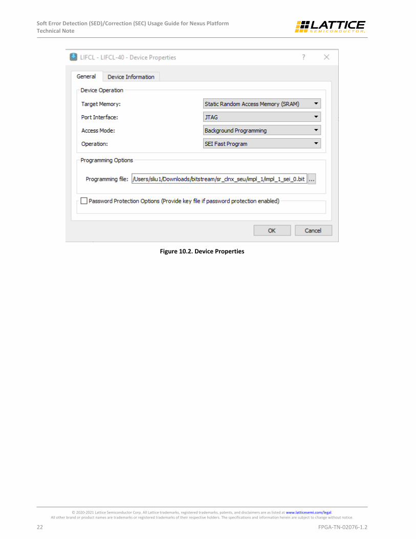
3. To program the one-bit-different bitstream, select the XSRAM SEI Fast Program operation in the Diamond Programmer.
4. Once it is programmed into the device, you can use the general SED routine to detect the soft error. During the SEI Fast Program, you can see the DONE pin go low during configuration and back to high after the configuration.
Note: While programming the device with soft error bitstream, SED checking has to stop. You can deassert SEDENABLE to stop the SED checking.
Soft Error Detection (SED)/Correction (SEC) Usage Guide for Nexus Platform Technical Note
© 2020-2021 Lattice Semiconductor Corp. All Lattice trademarks, registered trademarks, patents, and disclaimers are as listed at www.latticesemi.com/legal. All other brand or product names are trademarks or registered trademarks of their respective holders. The specifications and information herein are subject to change without notice.
22 FPGA-TN-02076-1.2
Figure 10.2. Device Properties
Soft Error Detection (SED)/Correction (SEC) Usage Guide for Nexus Platform Technical Note
© 2020-2021 Lattice Semiconductor Corp. All Lattice trademarks, registered trademarks, patents, and disclaimers are as listed at www.latticesemi.com/legal. All other brand or product names are trademarks or registered trademarks of their respective holders. The specifications and information herein are subject to change without notice.
FPGA-TN-02076-1.2 23
Technical Support Assistance Submit a technical support case through www.latticesemi.com/techsupport.

Soft Error Detection (SED)/Correction (SEC) Usage Guide for Nexus Platform Technical Note
© 2020-2021 Lattice Semiconductor Corp. All Lattice trademarks, registered trademarks, patents, and disclaimers are as listed at www.latticesemi.com/legal. All other brand or product names are trademarks or registered trademarks of their respective holders. The specifications and information herein are subject to change without notice.
24 FPGA-TN-02076-1.2
Revision History
Revision 1.2, June 2021
Section Change Summary
All Minor adjustments in formatting.
Introduction Added CertusPro-NX support.
Revision 1.1, June 2020
Section Change Summary
All Changed document name from CrossLink-NX Soft Error Detection/Correction Usage Guide to Soft Error Detection/Correction Usage Guide for Nexus Platform.
Added Nexus platform across the document.
Introduction Updated section content.
SEC Overview Updated section content.
Updated Figure 2.2 and Figure 2.3.
Port List Updated Table 3.1.
Port Descriptions Updated section content.
SED Clock and Reset Updated content to add Figure 5.1.
SED Flow Updated Figure 6.4.
Sample Code Updated codes in SED Verilog Example and SED VHDL Example.
Soft Error Injection (SEI) Added this section.
Revision 1.0, February 2020
Section Change Summary
All Initial release

www.latticesemi.com