so new it’s scarcely noticed, so old it’s almost forgotten principal inventor: d. c. hyland...
TRANSCRIPT

So new it’s scarcely noticed,So old it’s almost forgotten
Principal Inventor:
D. C. HylandTexas A&M University
Also contributed at the International Conference on SBSP, Kobe, Japan, April 2014
A Revolutionary Concept for Space Solar Power
1

Background
• All previous SPS concepts• Involve gigantic, complex, articulated structures• Contain numerous, perhaps 1000s, of moving parts• Require numerous launches• Require on-orbit fabrication/construction, usually robotic• Involve serious dynamic stability issues
• Power StarTM combines very new and very old technologies to obtain:
• The simplest possible structure• No moving parts (except electrons and photons)• One launch vehicle (A one-km system can fit into several
existing vehicles)• No on-orbit construction• Inherent dynamic stability and robustness
2

Substrate layer
Transmitter
Solar cell Solar cell
Conductive coating (ground)
Power connectors
Printed Solar Arrays Printed Patch Antennae
Solar-Microwave
Fabric
The New
• Solar collectors and microwave transmitters are printed on a thin fabric in a randomized pattern.
• The collectors and transmitters are combined in modules called “collectennas”TM.
• The fabric collects solar energy, converts to microwaves and transmits it with adaptively formed beam(s) using an entirely localized algorithm. (Two modes of operation:
• Passive Mode: A cooperative target sends a low amplitude beacon signal
• Active Mode: The Fabric transmits a tracking signal and the return from the target serves as a beacon signal
3

The Old: Echo Satellite Technology
4

Meridonial SectorsSpherical Balloon
Balloon Fabrication
5

Packaging and Deployment: One compact container, one launch
vehicle
Negligible final angular velocity
6

Rectenna Beacons
Beacon Radiation
Microwave Power
Printed microwave transmitter elements
Printed solar array elements
Random Tessellation to prevent grating lobes
In each patch antenna:
Local microprocessor records beacon radiation waveform
Amplifies waveform and emits it back in reverse time.
Power optimally matches desired power distribution on the ground.
No moving parts!
Exterior surface
Substrate layer
TransmitterSolar cell Solar cell
transceivers
Copper grid
Power connector
7
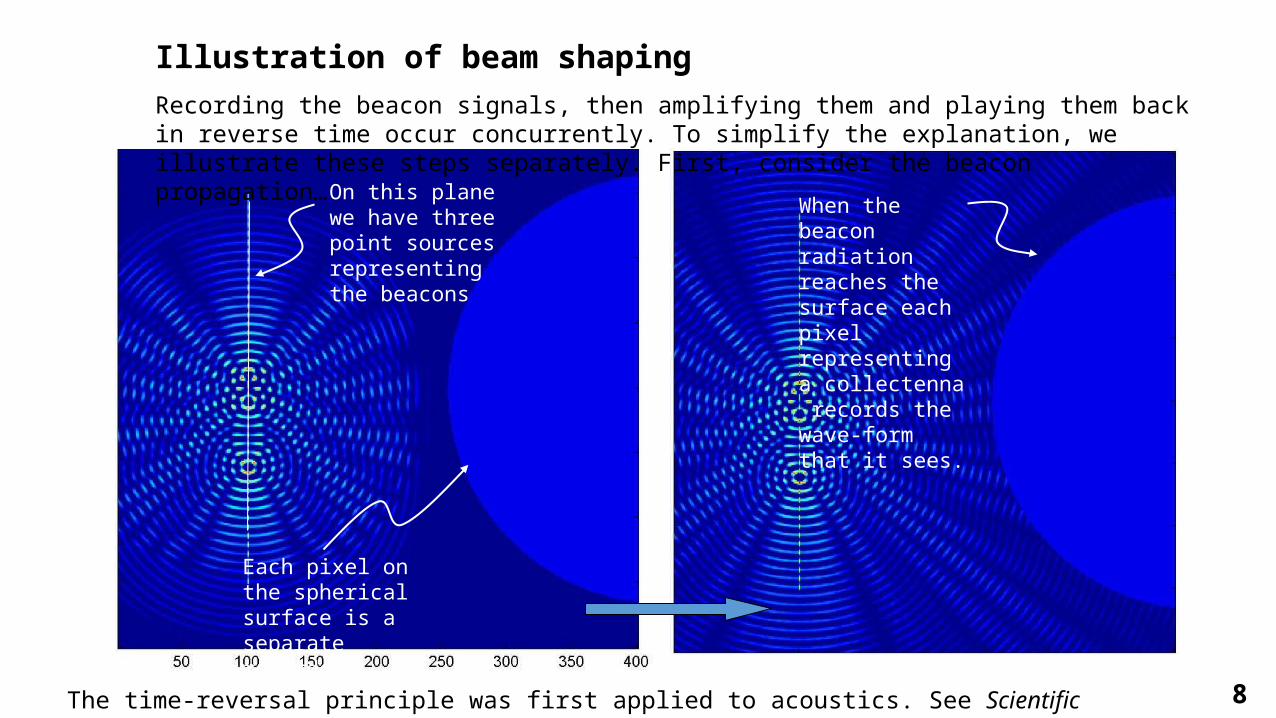
Illustration of beam shapingRecording the beacon signals, then amplifying them and playing them back in reverse time occur concurrently. To simplify the explanation, we illustrate these steps separately. First, consider the beacon propagation…
On this plane we have three point sources representing the beacons
Each pixel on the spherical surface is a separate recorder
When the beacon radiation reaches the surface each pixel representing a collectenna records the wave-form that it sees.
8The time-reversal principle was first applied to acoustics. See Scientific American, November 1999.

Now turn off the beacon and let each pixel on the surface re-transmit the wave-form it recorded - but in reverse time…
Note the converging wave fronts
Each pixel on the surface transmits the recorded signal in reverse time
The amplitude on the ground plane has three concentrations centered on the beacons. If the transmitting array were infinite in extent, these would be point concentrations.
9

Beacon radiation
Solar radiation
,S B
,S B
,S B
,S B
Interior surface printed with -wave receiver/transmitters (possibly shorter wavelengths)
, exterior surface illuminated by both sun and beacon
External solar arrays power local external transmitters
, exterior surface illuminated by sun but no beacon
External solar array
S B
S B
s power the local internal
receiver/transmitters & they transmit power to the
internal receiver/transmitters in sector ,
, exterior surface exposed to beacon, but not t
S B
S B
he sun
Exterior transmitters powered by the local interior
receiver/transmitters (that receive power from , )
, exterior surface shaded from both sun and beacon
Do nothing
S B
S B
Localized Power Distribution
10

Power Distribution - Summary• Each antenna transmits only if the beacon(s) radiation is
received.• Each transmitting antenna draws power from
• Solar cells in its immediate vicinity (within a few centimeters), or• Through the thickness of the “skin” from receivers on the inner surface
of the skin.
• Power transmission through the skin traverses a few centimeters or less. Each transmitter receives just a few Watts No high voltages, no large wires
• Power distribution to each antenna is local – there is no need for a complex power management system.
• Strictly local architecture means robustness against partial damage!
11

~ 1 km
w
Printed microwave transmitter elements
Printed solar array elements
Random Tessellation to prevent grating lobes
Summary Sketch of the Concept
Unique features:
Its structure is extremely simple and can be fit into many launch vehicle payload envelopes.
It can gather solar power from any angle and beam power in any direction (s) without slewing or structural deformation.
It has no moving parts.
It can optimally approximate any desired field distribution on the ground.
It requires no in-space assembly or construction
It has no control/structure feedback so the system is guaranteed dynamically stable.
The operation of the phased array is adaptive so that even if severely damaged, the system can retain some level of useful performance.
Substrate layer
Transmitter
Solar cell Solar cell
transceivers
12

An Extended Application:Placed at GEO, Power Star is easily designed to produce power densities that are safe for humans on the groundBut if an intruder should approach within just a few hundred kilometers, Power Star can be run in active mode and irradiate the target with enormous power density
13

Rapidly Deployable Power Generation / Air and Missile DefenseAt a forward operating base, lay out Solar-Microwave “rugs”.
Whatever the mode of operation, the rugs need not be flat nor does one need a continuous sheet (there can be minor gaps)
For power generation, use only the solar cells. If receiving power from Power Star, engage transceivers
Substrate layer
Transmitter
Solar cell Solar cell
Conductive coating (ground)
Power connectors
14

Rapidly Deployable Power Generation / Air and Missile DefenseUsing power direct from solar cells or another source, operate beam forming in active mode.
This means irradiate target, sense return and use as beacon signal. Beam forming proceeds as described for Power Star.
15