snmp mib user guide - cdn.raritan.comcdn.raritan.com/download/px3/version-3.4.0/mib... · snmp mib...
TRANSCRIPT
SNMP MIB User GuideRaritan Inc.
February 9, 2018
SNMP MIB User Guide CONTENTS
ContentsContents ii
1 Quick Start 11.1 Determine the status of an outlet . . . . . . . . . . . . . . . . . . . . . . 11.2 Power cycle an outlet . . . . . . . . . . . . . . . . . . . . . . . . . . . . . 21.3 Get the voltage reading of an inlet . . . . . . . . . . . . . . . . . . . . . 21.4 Get the number of decimal digits of an inlet voltage reading . . . . . . . 31.5 Receive a trap message on an external sensor alarm assertion . . . . . . . 41.6 Get an asset management tag ID . . . . . . . . . . . . . . . . . . . . . . 51.7 Set the name of a rack unit in asset management . . . . . . . . . . . . . 5
2 About this document 62.1 Scope . . . . . . . . . . . . . . . . . . . . . . . . . . . . . . . . . . . . . 62.2 Audience . . . . . . . . . . . . . . . . . . . . . . . . . . . . . . . . . . . . 62.3 Prerequisites . . . . . . . . . . . . . . . . . . . . . . . . . . . . . . . . . . 6
3 Capabilities 7
4 Access 84.1 SNMP Interface Configuration . . . . . . . . . . . . . . . . . . . . . . . . 84.2 Protocol Versions . . . . . . . . . . . . . . . . . . . . . . . . . . . . . . . 84.3 MIB Version . . . . . . . . . . . . . . . . . . . . . . . . . . . . . . . . . . 84.4 Authentication . . . . . . . . . . . . . . . . . . . . . . . . . . . . . . . . 9
5 Object Indexing 115.1 Scalar Objects . . . . . . . . . . . . . . . . . . . . . . . . . . . . . . . . . 115.2 Columnar Objects – Single Index . . . . . . . . . . . . . . . . . . . . . . 115.3 Columnar Objects – Multiple Indexes . . . . . . . . . . . . . . . . . . . . 13
6 MIB tree 16
7 Interpreting Sensor Values 187.1 Decimal Digits . . . . . . . . . . . . . . . . . . . . . . . . . . . . . . . . 187.2 Signed vs. Unsigned . . . . . . . . . . . . . . . . . . . . . . . . . . . . . 18
Page ii
SNMP MIB User Guide 1 QUICK START
1 Quick StartThis section contains some brief examples of tasks that can be performed on a PDU’sSNMP interface. All of them assume the following preconditions:
• SNMP was set up as shown in figure 1 and 2 in section 4.1
• the Net-SNMP tools are installed (see www.net-snmp.org)
• the MIB files (see section 4.3 how to get them) are located in the MIB search path,which can be adjusted by adding -M+<path> to the snmp command arguments
Each example will present the MIB object identifier to deal with and an SNMP commandline with related execution output. The object identifier includes the applicable variables,e. g. “<outlet number>” which are replaced with actual values in the command andoutput example.
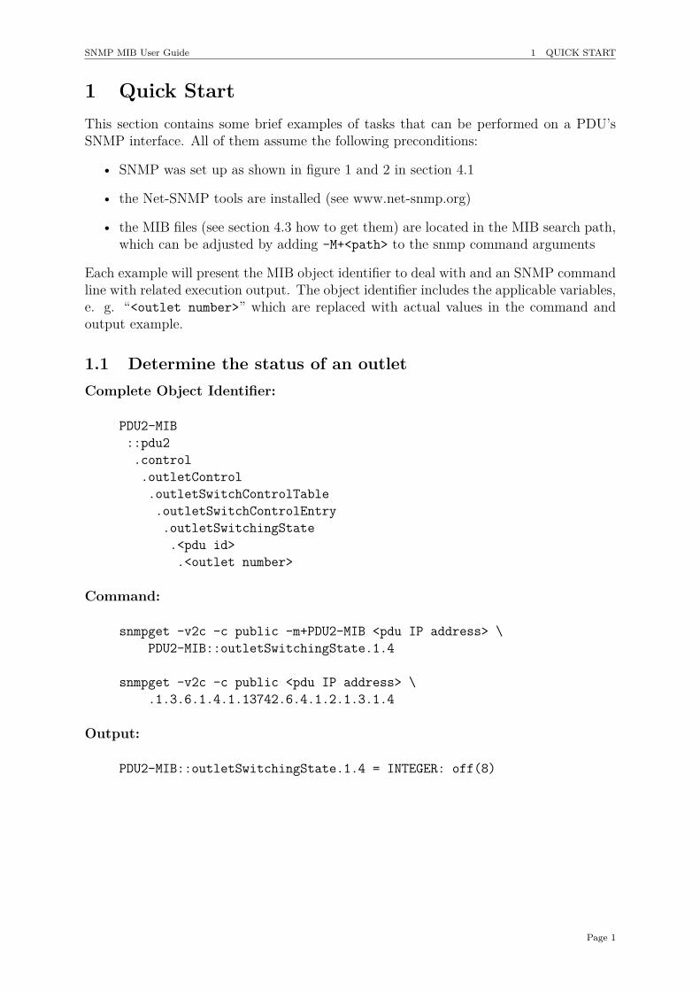
1.1 Determine the status of an outletComplete Object Identifier:
PDU2-MIB::pdu2.control.outletControl.outletSwitchControlTable.outletSwitchControlEntry.outletSwitchingState.<pdu id>.<outlet number>
Command:
snmpget -v2c -c public -m+PDU2-MIB <pdu IP address> \PDU2-MIB::outletSwitchingState.1.4
snmpget -v2c -c public <pdu IP address> \.1.3.6.1.4.1.13742.6.4.1.2.1.3.1.4
Output:
PDU2-MIB::outletSwitchingState.1.4 = INTEGER: off(8)
Page 1
SNMP MIB User Guide 1 QUICK START
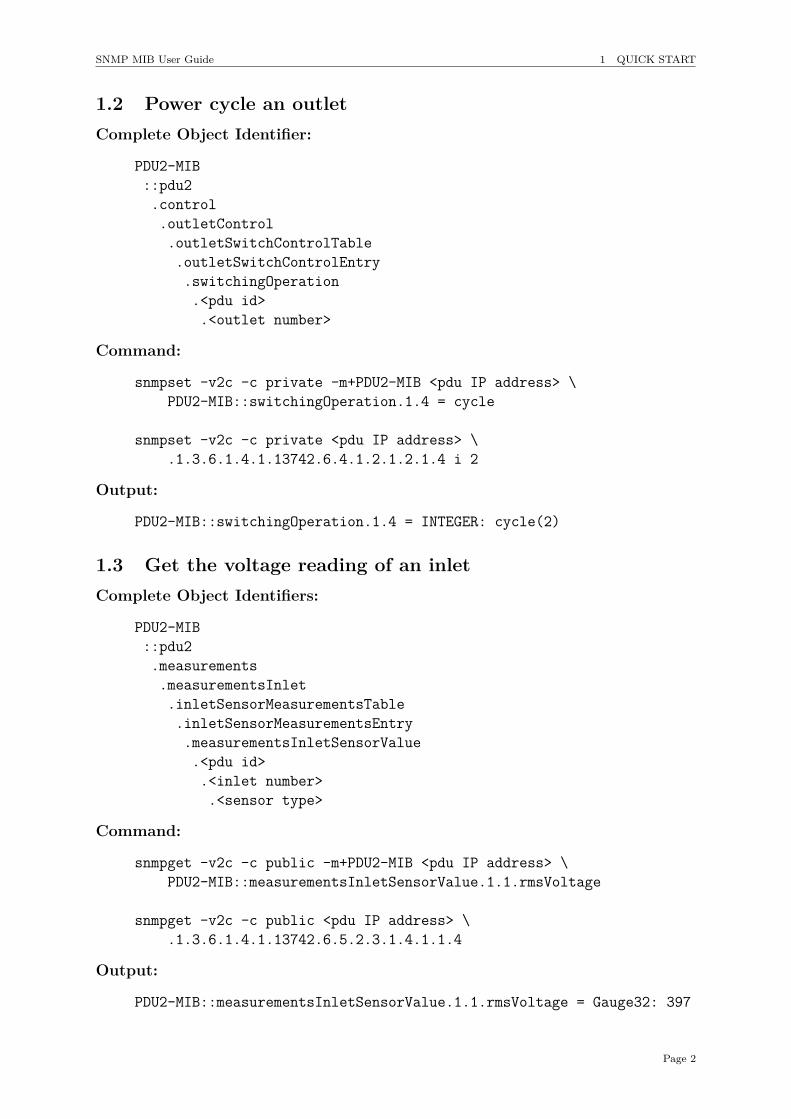
1.2 Power cycle an outletComplete Object Identifier:
PDU2-MIB::pdu2.control.outletControl.outletSwitchControlTable.outletSwitchControlEntry.switchingOperation.<pdu id>.<outlet number>
Command:
snmpset -v2c -c private -m+PDU2-MIB <pdu IP address> \PDU2-MIB::switchingOperation.1.4 = cycle
snmpset -v2c -c private <pdu IP address> \.1.3.6.1.4.1.13742.6.4.1.2.1.2.1.4 i 2
Output:
PDU2-MIB::switchingOperation.1.4 = INTEGER: cycle(2)
1.3 Get the voltage reading of an inletComplete Object Identifiers:
PDU2-MIB::pdu2.measurements.measurementsInlet.inletSensorMeasurementsTable.inletSensorMeasurementsEntry.measurementsInletSensorValue.<pdu id>.<inlet number>.<sensor type>
Command:
snmpget -v2c -c public -m+PDU2-MIB <pdu IP address> \PDU2-MIB::measurementsInletSensorValue.1.1.rmsVoltage
snmpget -v2c -c public <pdu IP address> \.1.3.6.1.4.1.13742.6.5.2.3.1.4.1.1.4
Output:
PDU2-MIB::measurementsInletSensorValue.1.1.rmsVoltage = Gauge32: 397
Page 2
SNMP MIB User Guide 1 QUICK START
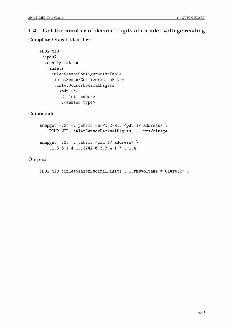
1.4 Get the number of decimal digits of an inlet voltage readingComplete Object Identifier:
PDU2-MIB::pdu2.configuration.inlets.inletSensorConfigurationTable.inletSensorConfigurationEntry.inletSensorDecimalDigits.<pdu id>.<inlet number>.<sensor type>
Command:
snmpget -v2c -c public -m+PDU2-MIB <pdu IP address> \PDU2-MIB::inletSensorDecimalDigits.1.1.rmsVoltage
snmpget -v2c -c public <pdu IP address> \.1.3.6.1.4.1.13742.6.3.3.4.1.7.1.1.4
Output:
PDU2-MIB::inletSensorDecimalDigits.1.1.rmsVoltage = Gauge32: 0
Page 3
SNMP MIB User Guide 1 QUICK START
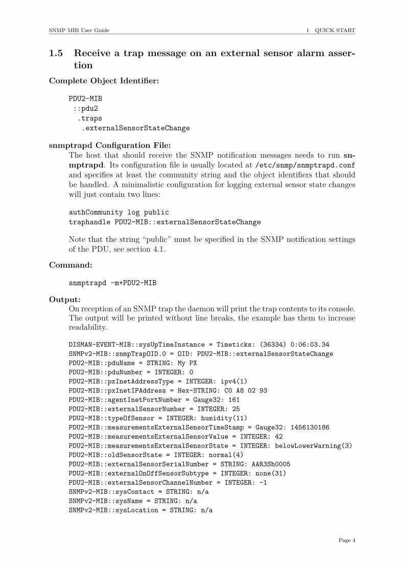
1.5 Receive a trap message on an external sensor alarm asser-tion
Complete Object Identifier:
PDU2-MIB::pdu2.traps.externalSensorStateChange
snmptrapd Configuration File:The host that should receive the SNMP notification messages needs to run sn-mptrapd. Its configuration file is usually located at /etc/snmp/snmptrapd.confand specifies at least the community string and the object identifiers that shouldbe handled. A minimalistic configuration for logging external sensor state changeswill just contain two lines:
authCommunity log publictraphandle PDU2-MIB::externalSensorStateChange
Note that the string “public” must be specified in the SNMP notification settingsof the PDU, see section 4.1.
Command:
snmptrapd -m+PDU2-MIB
Output:On reception of an SNMP trap the daemon will print the trap contents to its console.The output will be printed without line breaks, the example has them to increasereadability.
DISMAN-EVENT-MIB::sysUpTimeInstance = Timeticks: (36334) 0:06:03.34SNMPv2-MIB::snmpTrapOID.0 = OID: PDU2-MIB::externalSensorStateChangePDU2-MIB::pduName = STRING: My PXPDU2-MIB::pduNumber = INTEGER: 0PDU2-MIB::pxInetAddressType = INTEGER: ipv4(1)PDU2-MIB::pxInetIPAddress = Hex-STRING: C0 A8 02 93PDU2-MIB::agentInetPortNumber = Gauge32: 161PDU2-MIB::externalSensorNumber = INTEGER: 25PDU2-MIB::typeOfSensor = INTEGER: humidity(11)PDU2-MIB::measurementsExternalSensorTimeStamp = Gauge32: 1456130186PDU2-MIB::measurementsExternalSensorValue = INTEGER: 42PDU2-MIB::measurementsExternalSensorState = INTEGER: belowLowerWarning(3)PDU2-MIB::oldSensorState = INTEGER: normal(4)PDU2-MIB::externalSensorSerialNumber = STRING: AAR3Sh0005PDU2-MIB::externalOnOffSensorSubtype = INTEGER: none(31)PDU2-MIB::externalSensorChannelNumber = INTEGER: -1SNMPv2-MIB::sysContact = STRING: n/aSNMPv2-MIB::sysName = STRING: n/aSNMPv2-MIB::sysLocation = STRING: n/a
Page 4
SNMP MIB User Guide 1 QUICK START
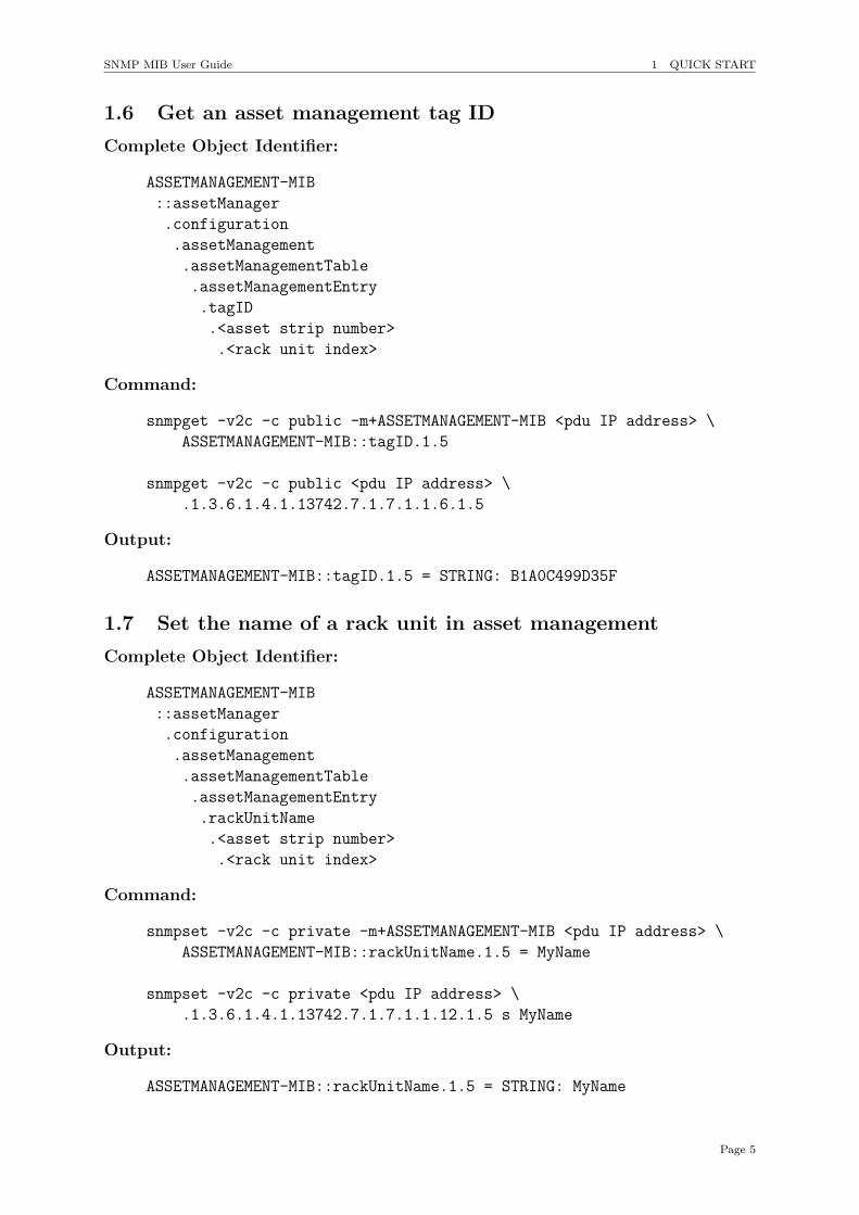
1.6 Get an asset management tag IDComplete Object Identifier:
ASSETMANAGEMENT-MIB::assetManager.configuration.assetManagement.assetManagementTable.assetManagementEntry.tagID.<asset strip number>.<rack unit index>
Command:
snmpget -v2c -c public -m+ASSETMANAGEMENT-MIB <pdu IP address> \ASSETMANAGEMENT-MIB::tagID.1.5
snmpget -v2c -c public <pdu IP address> \.1.3.6.1.4.1.13742.7.1.7.1.1.6.1.5
Output:
ASSETMANAGEMENT-MIB::tagID.1.5 = STRING: B1A0C499D35F
1.7 Set the name of a rack unit in asset managementComplete Object Identifier:
ASSETMANAGEMENT-MIB::assetManager.configuration.assetManagement.assetManagementTable.assetManagementEntry.rackUnitName.<asset strip number>.<rack unit index>
Command:
snmpset -v2c -c private -m+ASSETMANAGEMENT-MIB <pdu IP address> \ASSETMANAGEMENT-MIB::rackUnitName.1.5 = MyName
snmpset -v2c -c private <pdu IP address> \.1.3.6.1.4.1.13742.7.1.7.1.1.12.1.5 s MyName
Output:
ASSETMANAGEMENT-MIB::rackUnitName.1.5 = STRING: MyName
Page 5
SNMP MIB User Guide 2 ABOUT THIS DOCUMENT
2 About this document
2.1 ScopeThe Raritan PDU SNMP MIB User Guide provides information about the following:
• configuration, access and capabilities of the SNMP interface
• usage of tables
• structure of the PDU’s Management Information Base
This document applies to the following Raritan PDU devices:
• PX2 / PX3 / PX3TS
• EMX
• BCM2 / PMC
• BCM
• PXE
The very basics of the SNMP protocol and the SMI concepts are not covered. Toolslike MIB browsers or snmp utilities are not explained as well. This documents describeshow the SNMP interface of a Raritan PDU can be utilized by the SNMP protocol by forexample using such tools.
2.2 AudienceThis document should primarily guide
Data Center Operators who want to configure PDUs, request values or control statessporadically,
DCIM software developers who want to integrate PDUs into higher level manage-ment frameworks and
Script Developers who want to write code that uses the PDU’s SNMP interface.
2.3 PrerequisitesThis document presumes understanding of
• Structured Management Information (SMI),
• the Simple Network Management Protocol (SNMP) and
• Management Information Base (MIB) documents.
Page 6
SNMP MIB User Guide 3 CAPABILITIES
3 CapabilitiesThe SNMP interface has almost the same capabilities as the web interface and the serialcommand line interface. It can be used to:
• retrieve logged and current sensor measurements
• get notifications on events
• control actuators
• configure names, thresholds etc.
The following features are not accessable via SNMP:
• User Management
• Network Configuration
• Services Configuration
• Event Rule Configuration
Page 7
SNMP MIB User Guide 4 ACCESS
4 Access
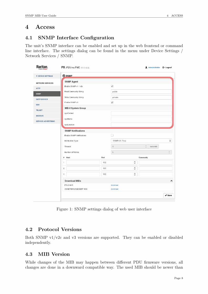
4.1 SNMP Interface ConfigurationThe unit’s SNMP interface can be enabled and set up in the web frontend or commandline interface. The settings dialog can be found in the menu under Device Settings /Network Services / SNMP.
Figure 1: SNMP settings dialog of web user interface
4.2 Protocol VersionsBoth SNMP v1/v2c and v3 versions are supported. They can be enabled or disabledindependently.
4.3 MIB VersionWhile changes of the MIB may happen between different PDU firmware versions, allchanges are done in a downward compatible way. The used MIB should be newer than
Page 8
SNMP MIB User Guide 4 ACCESS
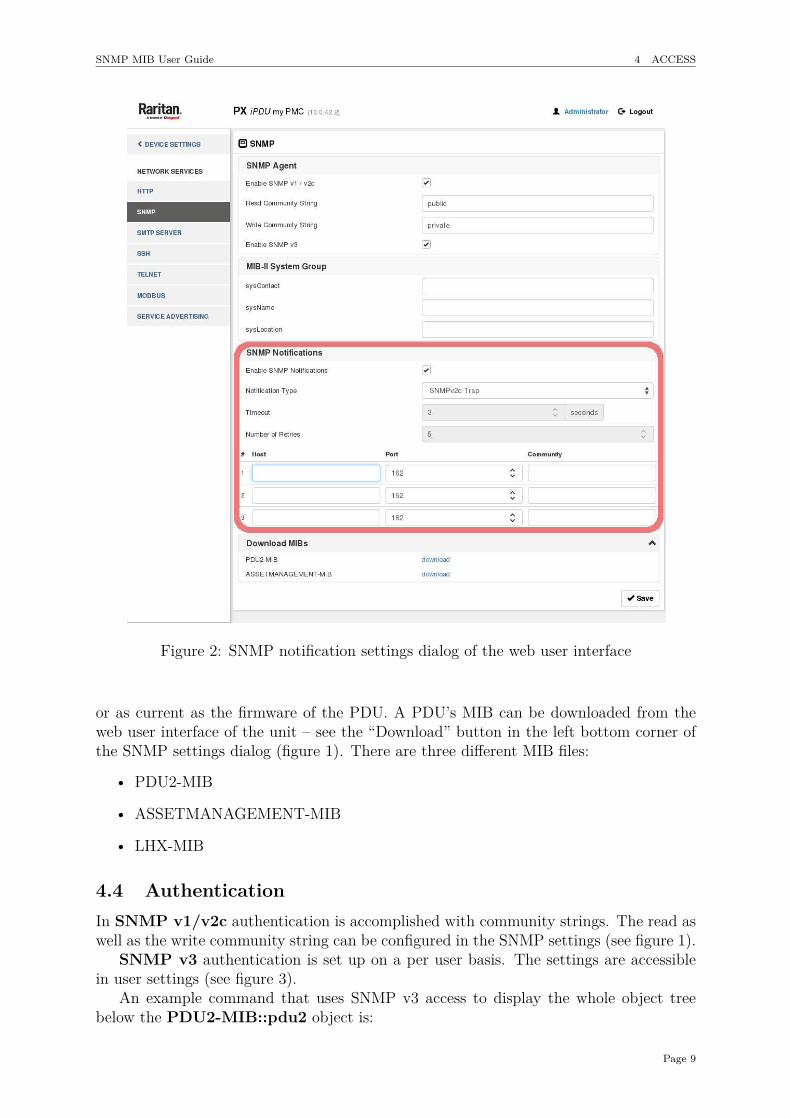
Figure 2: SNMP notification settings dialog of the web user interface
or as current as the firmware of the PDU. A PDU’s MIB can be downloaded from theweb user interface of the unit – see the “Download” button in the left bottom corner ofthe SNMP settings dialog (figure 1). There are three different MIB files:
• PDU2-MIB
• ASSETMANAGEMENT-MIB
• LHX-MIB
4.4 AuthenticationIn SNMP v1/v2c authentication is accomplished with community strings. The read aswell as the write community string can be configured in the SNMP settings (see figure 1).
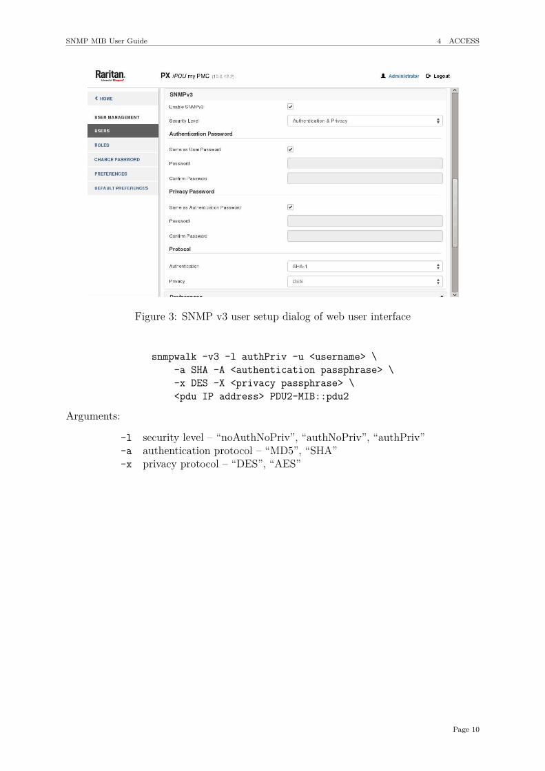
SNMP v3 authentication is set up on a per user basis. The settings are accessiblein user settings (see figure 3).
An example command that uses SNMP v3 access to display the whole object treebelow the PDU2-MIB::pdu2 object is:
Page 9
SNMP MIB User Guide 4 ACCESS
Figure 3: SNMP v3 user setup dialog of web user interface
snmpwalk -v3 -l authPriv -u <username> \-a SHA -A <authentication passphrase> \-x DES -X <privacy passphrase> \<pdu IP address> PDU2-MIB::pdu2
Arguments:
-l security level – “noAuthNoPriv”, “authNoPriv”, “authPriv”-a authentication protocol – “MD5”, “SHA”-x privacy protocol – “DES”, “AES”
Page 10
SNMP MIB User Guide 5 OBJECT INDEXING
5 Object Indexing
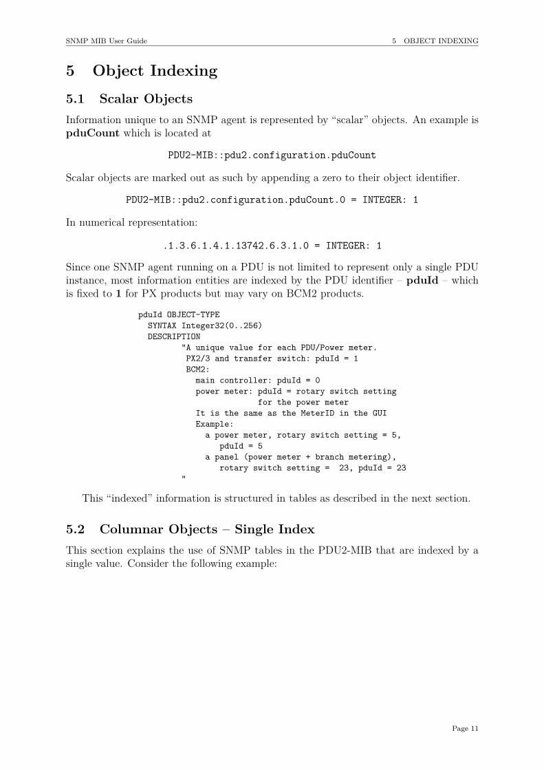
5.1 Scalar ObjectsInformation unique to an SNMP agent is represented by “scalar” objects. An example ispduCount which is located at
PDU2-MIB::pdu2.configuration.pduCount
Scalar objects are marked out as such by appending a zero to their object identifier.
PDU2-MIB::pdu2.configuration.pduCount.0 = INTEGER: 1
In numerical representation:
.1.3.6.1.4.1.13742.6.3.1.0 = INTEGER: 1
Since one SNMP agent running on a PDU is not limited to represent only a single PDUinstance, most information entities are indexed by the PDU identifier – pduId – whichis fixed to 1 for PX products but may vary on BCM2 products.
pduId OBJECT-TYPESYNTAX Integer32(0..256)DESCRIPTION
"A unique value for each PDU/Power meter.PX2/3 and transfer switch: pduId = 1BCM2:
main controller: pduId = 0power meter: pduId = rotary switch setting
for the power meterIt is the same as the MeterID in the GUIExample:
a power meter, rotary switch setting = 5,pduId = 5
a panel (power meter + branch metering),rotary switch setting = 23, pduId = 23
"
This “indexed” information is structured in tables as described in the next section.
5.2 Columnar Objects – Single IndexThis section explains the use of SNMP tables in the PDU2-MIB that are indexed by asingle value. Consider the following example:
Page 11
SNMP MIB User Guide 5 OBJECT INDEXING
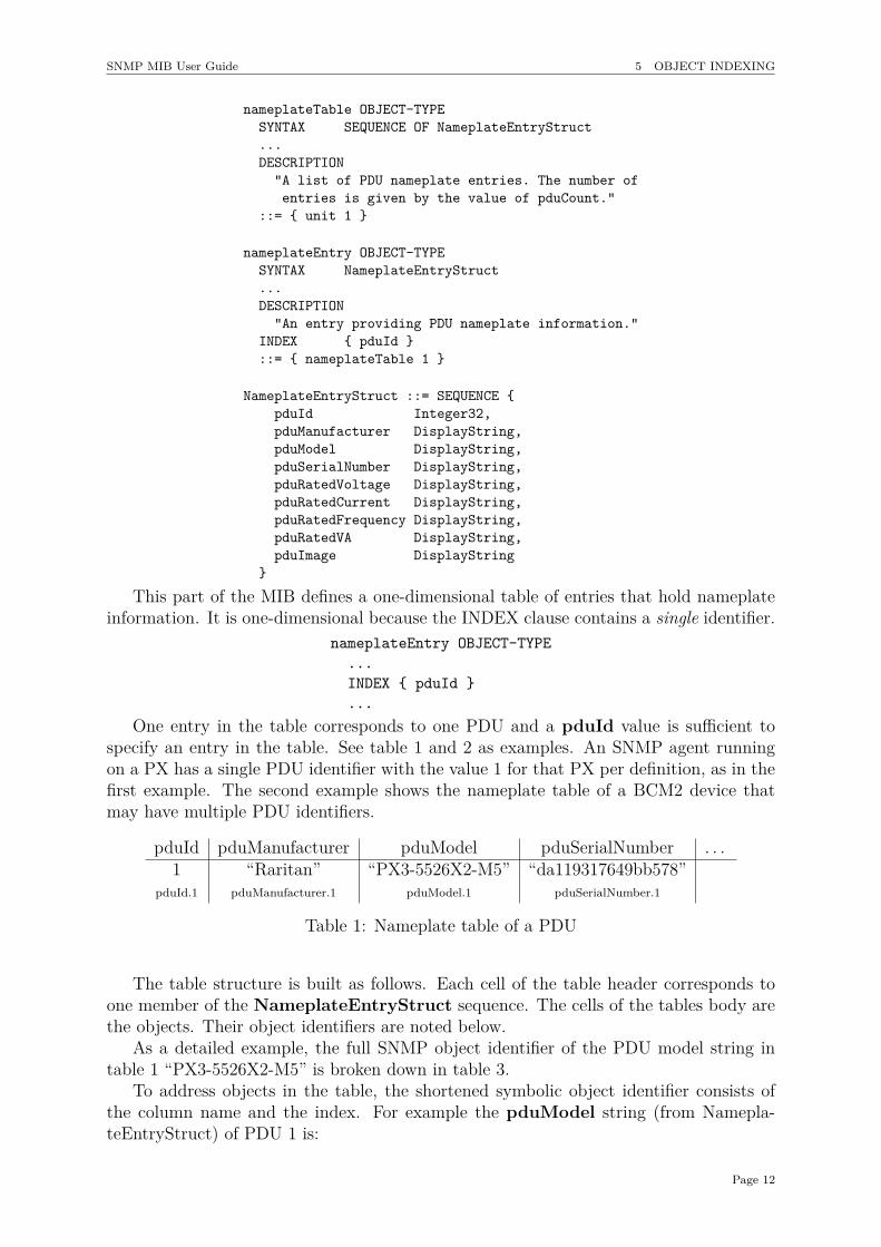
nameplateTable OBJECT-TYPESYNTAX SEQUENCE OF NameplateEntryStruct...DESCRIPTION
"A list of PDU nameplate entries. The number ofentries is given by the value of pduCount."
::= { unit 1 }
nameplateEntry OBJECT-TYPESYNTAX NameplateEntryStruct...DESCRIPTION
"An entry providing PDU nameplate information."INDEX { pduId }::= { nameplateTable 1 }
NameplateEntryStruct ::= SEQUENCE {pduId Integer32,pduManufacturer DisplayString,pduModel DisplayString,pduSerialNumber DisplayString,pduRatedVoltage DisplayString,pduRatedCurrent DisplayString,pduRatedFrequency DisplayString,pduRatedVA DisplayString,pduImage DisplayString
}
This part of the MIB defines a one-dimensional table of entries that hold nameplateinformation. It is one-dimensional because the INDEX clause contains a single identifier.
nameplateEntry OBJECT-TYPE...INDEX { pduId }...
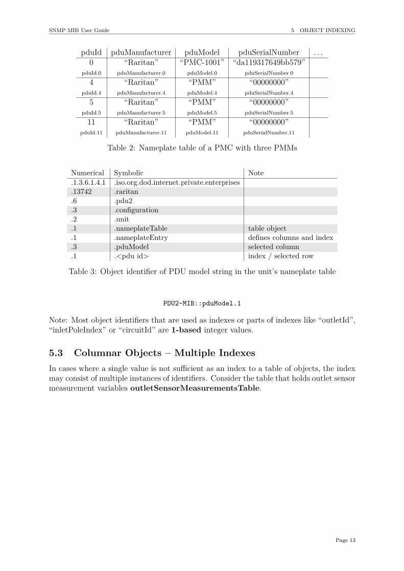
One entry in the table corresponds to one PDU and a pduId value is sufficient tospecify an entry in the table. See table 1 and 2 as examples. An SNMP agent runningon a PX has a single PDU identifier with the value 1 for that PX per definition, as in thefirst example. The second example shows the nameplate table of a BCM2 device thatmay have multiple PDU identifiers.
pduId pduManufacturer pduModel pduSerialNumber . . .1 “Raritan” “PX3-5526X2-M5” “da119317649bb578”
pduId.1 pduManufacturer.1 pduModel.1 pduSerialNumber.1
Table 1: Nameplate table of a PDU
The table structure is built as follows. Each cell of the table header corresponds toone member of the NameplateEntryStruct sequence. The cells of the tables body arethe objects. Their object identifiers are noted below.
As a detailed example, the full SNMP object identifier of the PDU model string intable 1 “PX3-5526X2-M5” is broken down in table 3.
To address objects in the table, the shortened symbolic object identifier consists ofthe column name and the index. For example the pduModel string (from Namepla-teEntryStruct) of PDU 1 is:
Page 12
SNMP MIB User Guide 5 OBJECT INDEXING
pduId pduManufacturer pduModel pduSerialNumber . . .0 “Raritan” “PMC-1001” “da119317649bb579”
pduId.0 pduManufacturer.0 pduModel.0 pduSerialNumber.0
4 “Raritan” “PMM” “00000000”pduId.4 pduManufacturer.4 pduModel.4 pduSerialNumber.4
5 “Raritan” “PMM” “00000000”pduId.5 pduManufacturer.5 pduModel.5 pduSerialNumber.5
11 “Raritan” “PMM” “00000000”pduId.11 pduManufacturer.11 pduModel.11 pduSerialNumber.11
Table 2: Nameplate table of a PMC with three PMMs
Numerical Symbolic Note.1.3.6.1.4.1 .iso.org.dod.internet.private.enterprises.13742 .raritan.6 .pdu2.3 .configuration.2 .unit.1 .nameplateTable table object.1 .nameplateEntry defines columns and index.3 .pduModel selected column.1 .<pdu id> index / selected row
Table 3: Object identifier of PDU model string in the unit’s nameplate table
PDU2-MIB::pduModel.1
Note: Most object identifiers that are used as indexes or parts of indexes like “outletId”,“inletPoleIndex” or “circuitId” are 1-based integer values.
5.3 Columnar Objects – Multiple IndexesIn cases where a single value is not sufficient as an index to a table of objects, the indexmay consist of multiple instances of identifiers. Consider the table that holds outlet sensormeasurement variables outletSensorMeasurementsTable.
Page 13
SNMP MIB User Guide 5 OBJECT INDEXING
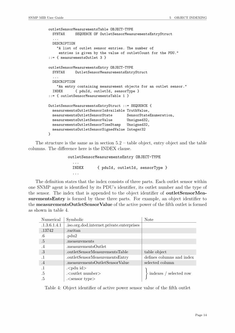
outletSensorMeasurementsTable OBJECT-TYPESYNTAX SEQUENCE OF OutletSensorMeasurementsEntryStruct...DESCRIPTION
"A list of outlet sensor entries. The number ofentries is given by the value of outletCount for the PDU."
::= { measurementsOutlet 3 }
outletSensorMeasurementsEntry OBJECT-TYPESYNTAX OutletSensorMeasurementsEntryStruct...DESCRIPTION
"An entry containing measurement objects for an outlet sensor."INDEX { pduId, outletId, sensorType }
::= { outletSensorMeasurementsTable 1 }
OutletSensorMeasurementsEntryStruct ::= SEQUENCE {measurementsOutletSensorIsAvailable TruthValue,measurementsOutletSensorState SensorStateEnumeration,measurementsOutletSensorValue Unsigned32,measurementsOutletSensorTimeStamp Unsigned32,measurementsOutletSensorSignedValue Integer32
}
The structure is the same as in section 5.2 – table object, entry object and the tablecolumns. The difference here is the INDEX clause.
outletSensorMeasurementsEntry OBJECT-TYPE...INDEX { pduId, outletId, sensorType }...
The definition states that the index consists of three parts. Each outlet sensor withinone SNMP agent is identified by its PDU’s identifier, its outlet number and the type ofthe sensor. The index that is appended to the object identifier of outletSensorMea-surementsEntry is formed by these three parts. For example, an object identifier tothe measurementsOutletSensorValue of the active power of the fifth outlet is formedas shown in table 4.
Numerical Symbolic Note.1.3.6.1.4.1 .iso.org.dod.internet.private.enterprises.13742 .raritan.6 .pdu2.5 .measurements.4 .measurementsOutlet.3 .outletSensorMeasurementsTable table object.1 .outletSensorMeasurementsEntry defines columns and index.4 .measurementsOutletSensorValue selected column.1 .<pdu id> }
indexes / selected row.5 .<outlet number>.5 .<sensor type>
Table 4: Object identifier of active power sensor value of the fifth outlet
Page 14
SNMP MIB User Guide 5 OBJECT INDEXING
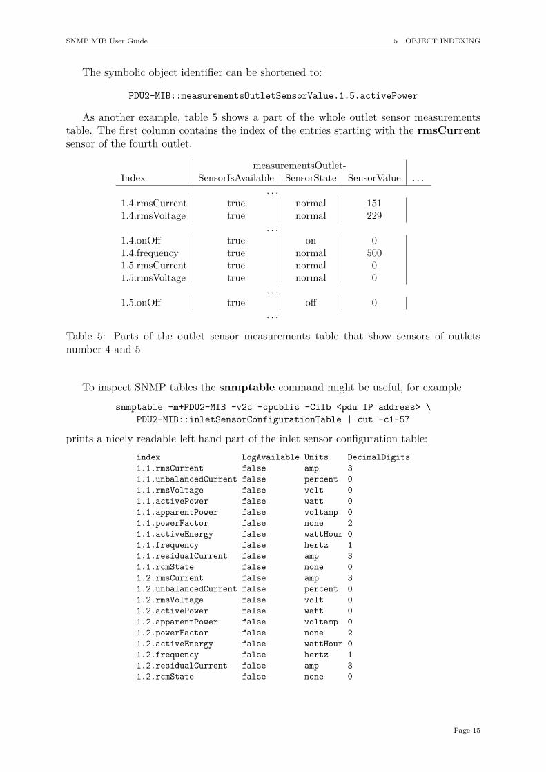
The symbolic object identifier can be shortened to:
PDU2-MIB::measurementsOutletSensorValue.1.5.activePower
As another example, table 5 shows a part of the whole outlet sensor measurementstable. The first column contains the index of the entries starting with the rmsCurrentsensor of the fourth outlet.
measurementsOutlet-Index SensorIsAvailable SensorState SensorValue . . .
. . .1.4.rmsCurrent true normal 1511.4.rmsVoltage true normal 229
. . .1.4.onOff true on 01.4.frequency true normal 5001.5.rmsCurrent true normal 01.5.rmsVoltage true normal 0
. . .1.5.onOff true off 0
. . .
Table 5: Parts of the outlet sensor measurements table that show sensors of outletsnumber 4 and 5
To inspect SNMP tables the snmptable command might be useful, for examplesnmptable -m+PDU2-MIB -v2c -cpublic -Cilb <pdu IP address> \
PDU2-MIB::inletSensorConfigurationTable | cut -c1-57
prints a nicely readable left hand part of the inlet sensor configuration table:index LogAvailable Units DecimalDigits1.1.rmsCurrent false amp 31.1.unbalancedCurrent false percent 01.1.rmsVoltage false volt 01.1.activePower false watt 01.1.apparentPower false voltamp 01.1.powerFactor false none 21.1.activeEnergy false wattHour 01.1.frequency false hertz 11.1.residualCurrent false amp 31.1.rcmState false none 01.2.rmsCurrent false amp 31.2.unbalancedCurrent false percent 01.2.rmsVoltage false volt 01.2.activePower false watt 01.2.apparentPower false voltamp 01.2.powerFactor false none 21.2.activeEnergy false wattHour 01.2.frequency false hertz 11.2.residualCurrent false amp 31.2.rcmState false none 0
Page 15

SNMP MIB User Guide 6 MIB TREE
6 MIB treeThis section describes the basic structure of the PDU2-MIB tree. The following clip ofthe PDU2-MIB file shows the various subtrees that reside below the PDU2-MIB::pdu2object:
raritan MODULE-IDENTITY...
::= { enterprises 13742 }
pdu2 OBJECT IDENTIFIER ::= { raritan 6 }
traps OBJECT IDENTIFIER ::= { pdu2 0 }board OBJECT IDENTIFIER ::= { pdu2 1 }environmental OBJECT IDENTIFIER ::= { pdu2 2 }configuration OBJECT IDENTIFIER ::= { pdu2 3 }control OBJECT IDENTIFIER ::= { pdu2 4 }measurements OBJECT IDENTIFIER ::= { pdu2 5 }log OBJECT IDENTIFIER ::= { pdu2 6 }conformance OBJECT IDENTIFIER ::= { pdu2 9 }reliability OBJECT IDENTIFIER ::= { pdu2 10 }
The subtree configuration contains most of the information that is writable / con-figurable. The measurements and log subtrees contain sensor values and state infor-mation. The control subtree allows manipulation of the PDU such as switching outletsor resetting energy counters.
Table 6 shows the most commonly used tables of the PDU2-MIB. Each cell rep-resents a name that is built by its column name and its row name appended. An “x”mark states that a table with this name can actually be found in the MIB. For example:unitConfigurationTable does exist while unitPoleConfigurationTable does not.
Prefixesover-
Current- power- transfer-Tables unit inlet outlet Protector Meter circuit Switch
ConfigurationTable x x x x x x xPoleConfigurationTable x x x x x
SensorConfigurationTable x x x x x xPoleSensorConfigurationTable x x x
SwitchControlTable x x1
SensorControlTable x x x xSensorMeasurementsTable x x x x x x
PoleSensorMeasurementsTable x x xSensorLogTable x x x x x x
PoleSensorLogTable x x x
Table 6: Table names present in the MIB
The particular contents of these tables are quite common:-ConfigurationTable
Contains metadata, capabilities, configuration and state information of the PDU’sparts; for example the current rating of an outlet or the unit’s IP address.
1The actual name is “transferSwitchControlTable” rather than transferSwitchSwitchControlTable.
Page 16
SNMP MIB User Guide 6 MIB TREE
-SensorConfigurationTableContains sensor metadata such as accuracy or tolerance and the sensors’ thresholds.
-SwitchControlTableContains objects that allow switching of outlets or between inlets of a transferswitch.
-SensorControlTableContains objects that allow resetting of cumulating sensor values such as energycounters.
-SensorMeasurementsTableContains sensor readings and state information.
-SensorLogTableContains objects to access logged measurements data such as minimum, maximumand average values.
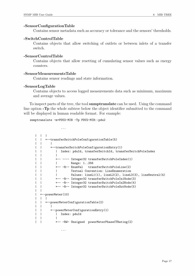
To inspect parts of the tree, the tool snmptranslate can be used. Using the commandline option -Tp the whole subtree below the object identifier submitted to the commandwill be displayed in human readable format. For example:
snmptranslate -m+PDU2-MIB -Tp PDU2-MIB::pdu2
...
| | || | +--transferSwitchPoleConfigurationTable(5)| | || | +--transferSwitchPoleConfigurationEntry(1)| | | Index: pduId, transferSwitchId, transferSwitchPoleIndex| | || | +-- ---- Integer32 transferSwitchPoleIndex(1)| | | Range: 1..256| | +-- -R-- EnumVal transferSwitchPoleLine(2)| | | Textual Convention: LineEnumeration| | | Values: lineL1(1), lineL2(2), lineL3(3), lineNeutral(4)| | +-- -R-- Integer32 transferSwitchPoleIn1Node(3)| | +-- -R-- Integer32 transferSwitchPoleIn2Node(4)| | +-- -R-- Integer32 transferSwitchPoleOutNode(5)| || +--powerMeter(10)| | || | +--powerMeterConfigurationTable(2)| | || | +--powerMeterConfigurationEntry(1)| | | Index: pduId| | || | +-- -RW- Unsigned powerMeterPhaseCTRating(2)
...
Page 17
SNMP MIB User Guide 7 INTERPRETING SENSOR VALUES
7 Interpreting Sensor Values
7.1 Decimal DigitsAll sensor readings are reported as integer values. Since the actual values may havefractional parts, it could be necessary to adjust to the number of decimal digits. Thereforeeach SensorConfigurationTable has a column called DecimalDigits. See section 1.4for an example. To calculate the actual value the integer reading value must be dividedby ten to the power of the decimal digits. Additionally, the column SensorUnits of theSensorConfigurationTable can be read to determine the unit of the reading.
For example:PDU2-MIB::inletSensorDecimalDigits.1.1.rmsCurrent = Gauge32: 3PDU2-MIB::measurementsInletSensorValue.1.1.rmsCurrent = Gauge32: 1424PDU2-MIB::inletSensorUnits.1.1.rmsCurrent = INTEGER: amp(2)
These values would mean that the inlet current is 1424103 = 1.424 A.
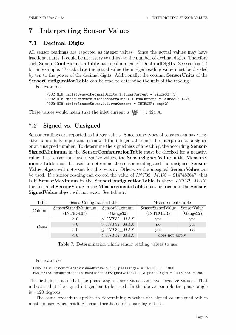
7.2 Signed vs. UnsignedSensor readings are reported as integer values. Since some types of sensors can have neg-ative values it is important to know if the integer value must be interpreted as a signedor an unsigned number. To determine the signedness of a reading, the according Sensor-SignedMinimum in the SensorConfigurationTable must be checked for a negativevalue. If a sensor can have negative values, the SensorSignedValue in the Measure-mentsTable must be used to determine the sensor reading and the unsigned Sensor-Value object will not exist for this sensor. Otherwise the unsigned SensorValue canbe used. If a sensor reading can exceed the value of INT32_MAX = 2147483647, thatis if SensorMaximum in the SensorConfigurationTable is above INT32_MAX,the unsigned SensorValue in the MeasurementsTable must be used and the Sensor-SignedValue object will not exist. See table 7.
Table SensorConfigurationTable MeasurementsTable
Column SensorSignedMinimum SensorMaximum SensorSignedValue SensorValue(INTEGER) (Gauge32) (INTEGER) (Gauge32)
Cases
≥ 0 ≤ INT32_MAX yes yes≥ 0 > INT32_MAX no yes< 0 ≤ INT32_MAX yes no< 0 > INT32_MAX does not apply
Table 7: Determination which sensor reading values to use.
For example:PDU2-MIB::circuitSensorSignedMinimum.1.1.phaseAngle = INTEGER: -1800PDU2-MIB::measurementsInletPoleSensorSignedValue.1.1.3.phaseAngle = INTEGER: -1200
The first line states that the phase angle sensor value can have negative values. Thatindicates that the signed integer has to be used. In the above example the phase angleis −120 degrees.
The same procedure applies to determining whether the signed or unsigned valuesmust be used when reading sensor thresholds or sensor log entries.
Page 18