smokegard 10-1-2013 smokegard 2012 reset key type b aluminium fascia grille test facility indication...
TRANSCRIPT

UDC 697.9
DAMPERS 2 JAN 2013
SFB (57.9) X
Features- Slimline construction.
- Smoke or fire operated.
- Stainless steel interlocking blades and side seals for maximumsmoke retardation.
- Galvanised steel frame.
- Easy key reset.
- 1 hour door & 2 hour wall mounting fire ratings.
SMOKEGARDDoor, Wall and Partition MountingSmoke and Fire Dampers

Introduction Gilberts Smokegard Dampers provide a
revolutionary “Engineered’ answer to the problem
of smoke and fire protection in fire doors, walls
and partitions. A unique patented blade linkage
mechanism has produced a Damper narrow
enough to fit within the confines of a 1/2 hour
(44mm) door, 1 hour (54mm) door or any
wall/partition and allow the passage of ventilation
air in normal conditions but prevent the spread of
smoke and flames in fire conditions.
Five modes of operation are available (3x failsafe
closed and 2x failsafe open) ranging from basic
Mode A, which is Fire only operated, to the Mode
C which is Fire and Smoke operated and
complete with in built status indicators. All units
comprise of a Galvanised Steel Frame with
Stainless Steel Inter-Locking Blades and Side
Seals, combining rugged construction with
maximum Fire and Smoke retardation
capabilities whilst the inter-connecting Rack
Blade operation feature is incorporated to ensure
faultless precision Damper Operation.
Fire tested to BRITISH STANDARD 476 PART 20
1987 the units are 2 hour rated, having been
tested for 4 hours in a wall and 1 hour in a door.
- Five control modes available
- Available in Fire or Smoke & Fire modes
- Interlocking Stainless Steel blades and frame
side seals provide a tight seal against smoke
and flames
- Fusible link elements close the Damper
instantly at between 70/80°C
- Galvanised Steel frame construction to resist
corrosion
- Simple key reset mechanism in the event of
activation
- Indication lights available to provide a visual
display of Damper status
- Integral test facility provided on Mode C
2
SMOKEGARDDoor, Wall and Partition Mounting Smoke and Fire Dampers
After opening Fusible
Link is fitted onto pins
Open using Reset Key
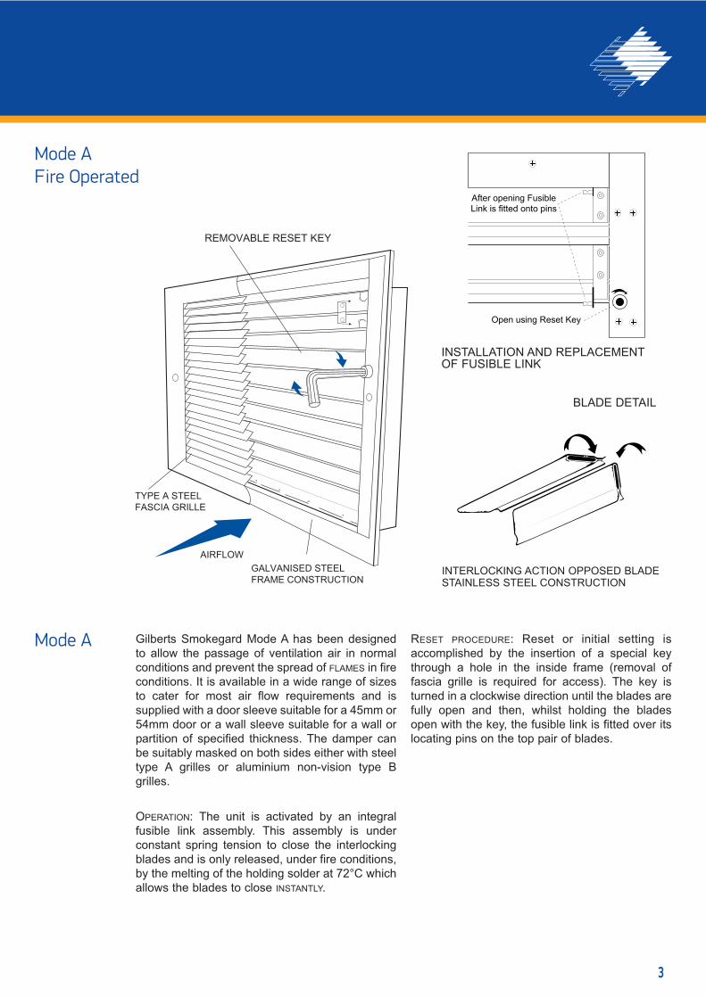
Mode A
INSTALLATION AND REPLACEMENTOF FUSIBLE LINK
BLADE DETAIL
INTERLOCKING ACTION OPPOSED BLADESTAINLESS STEEL CONSTRUCTION
REMOVABLE RESET KEY
TYPE A STEELFASCIA GRILLE
AIRFLOWGALVANISED STEEL FRAME CONSTRUCTION
Mode AFire Operated
3
Gilberts Smokegard Mode A has been designed
to allow the passage of ventilation air in normal
conditions and prevent the spread of FLAMES in fire
conditions. It is available in a wide range of sizes
to cater for most air flow requirements and is
supplied with a door sleeve suitable for a 45mm or
54mm door or a wall sleeve suitable for a wall or
partition of specified thickness. The damper can
be suitably masked on both sides either with steel
type A grilles or aluminium non-vision type B
grilles.
OPERATION: The unit is activated by an integral
fusible link assembly. This assembly is under
constant spring tension to close the interlocking
blades and is only released, under fire conditions,
by the melting of the holding solder at 72°C which
allows the blades to close INSTANTLY.
RESET PROCEDURE: Reset or initial setting is
accomplished by the insertion of a special key
through a hole in the inside frame (removal of
fascia grille is required for access). The key is
turned in a clockwise direction until the blades are
fully open and then, whilst holding the blades
open with the key, the fusible link is fitted over its
locating pins on the top pair of blades.
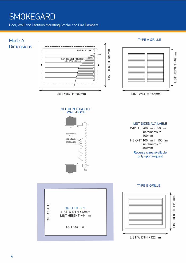
Mode ADimensions
FUSIBLE LINK
KEY RE-SET POSITIONBEHIND GRILLE
CUT OUT SIZE
LIST WIDTH +42mm
LIST HEIGHT +44mm
CUT OUT ‘W’
CU
T O
UT
‘H
’
LIST SIZES AVAILABLE
WIDTH 200mm in 50mm
increments to
400mm
HEIGHT 100mm in 100mm
increments to
400mm
Reverse sizes available
only upon request
LIS
T H
EIG
HT
+92m
m
TYPE B GRILLE
LIS
T H
EIG
HT
+110m
m
LIST WIDTH +122mm
LIST WIDTH +85mm
LIS
T H
EIG
HT
+84m
m
LIST WIDTH +80mm
DOOR OR WALL
SLEEVE
(WALL SLEEVE
DEPTH VARIABLE
PLEASE STATE
REQUIREMENTS)
29mm
DAMPER
SECTION THROUGHWALL/DOOR
TYPE A GRILLE
4
SMOKEGARDDoor, Wall and Partition Mounting Smoke and Fire Dampers
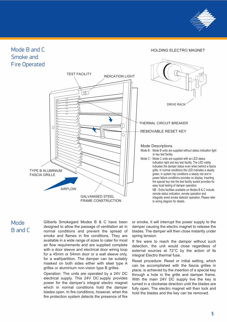
REMOVABLE RESET KEY
TYPE B ALUMINIUMFASCIA GRILLE
TEST FACILITY INDICATION LIGHT
THERMAL CIRCUIT BREAKER
AIRFLOW
GALVANISED STEEL FRAME CONSTRUCTION
DRIVE RACK
Gilberts Smokegard Modes B & C have been
designed to allow the passage of ventilation air in
normal conditions and prevent the spread of
smoke and flames in fire conditions. They are
available in a wide range of sizes to cater for most
air flow requirements and are supplied complete
with a door sleeve and electrical door wiring loop
for a 45mm or 54mm door or a wall sleeve only,
for a wall/partition. The damper can be suitably
masked on both sides either with steel type A
grilles or aluminium non-vision type B grilles.
Operation: The units are operated by a 24V DC
electrical supply. This 24V DC supply provides
power for the damper’s integral electro magnet
which in normal conditions hold the damper
blades open. In fire conditions, however, when the
fire protection system detects the presence of fire
or smoke, it will interrupt the power supply to the
damper causing the electro magnet to release the
blades. The damper will then close instantly under
spring tension.
If fire were to reach the damper without such
detection, the unit would close regardless of
external sources at 72°C by the action of its
integral Electro thermal fuse.
Reset procedure: Reset or initial setting, which
can be accomplished with the fascia grilles in
place, is achieved by the insertion of a special key
through a hole in the grille and damper frame.
With the main 24V DC supply live the key is
turned in a clockwise direction until the blades are
fully open. The electro magnet will then lock and
hold the blades and the key can be removed.
Mode DescriptionsMode B - Mode B units are supplied without status indication light
or key test facility.
Mode C - Mode C units are supplied with an LED statusindication light and key test facility. The LED visiblyindicates the damper status even when behind a fasciagrille. In normal conditions the LED indicates a steadygreen; in system trip conditions a steady red and inpower failure conditions provides no display. Insertingthe special key into the test facility socket provides foreasy local testing of damper operation.
NB - Extra facilities available on Modes B & C includeremote status indication, remote operation andintegrally wired smoke detector operation. Please referto wiring diagram for details.
Mode B and C
HOLDING ELECTRO MAGNETMode B and CSmoke andFire Operated
5

Mode B and CDimensions
TYPE A GRILLE
LIS
T H
EIG
HT
+120m
m
LIST WIDTH +85mm
FUSIBLE LINK
KEY RE-SET POSITIONBEHIND GRILLE
LIS
T H
EIG
HT
+114m
m
LIST WIDTH +80mm
CUT OUT SIZE
LIST WIDTH +42mm
LIST HEIGHT +78mm
CUT OUT ‘W’
CU
T O
UT
‘H
’
LIST SIZES AVAILABLE
WIDTH 200mm in 50mm
increments to
400mm
HEIGHT 100mm in 100mm
increments to
400mm
Reverse sizes available
upon only request
TYPE B GRILLE
LIS
T H
EIG
HT
+144m
m
LIST WIDTH +122mm
DOOR OR WALL
SLEEVE
(WALL SLEEVE
DEPTH VARIABLE
PLEASE STATE
REQUIREMENTS)
29mm
DAMPER
SECTION THROUGHWALL/DOOR
LED+KEY TEST
HOLES MODE C
ONLY
6
SMOKEGARDDoor, Wall and Partition Mounting Smoke and Fire Dampers

AncillaryItems
Gilberts range of ancillary Items have been designed for use in conjunction with Smokegard Damper Modes B
& C. Purpose made for straight forward connection to the units they offer a number of useful services.
Remote IndicatorsGilberts remote indicator panels can be
linked to Damper Modes B & C and
provide remote indication of the status of
one damper. Powered by the yellow and
blue switch wires from the Smokegard and
the -VE DC supply the panel LED indicates
Green - Damper Open
Red - Damper Closed
No Light - No Supply Voltage - Damper Closed
Ref:- SRI 1
Master MonitorA more advanced form of remote
indication is available with a master
monitor. This unit provides remote
indication for the status of up to 12
individual dampers. Details as for Remote
Indicator.
Ref:- SMM1-12*
* dependant on number of dampers on the
system
Smoke DetectorsSmoke Detectors are available for ceiling mounting and can link directly into Modes B
or C or the output relay of the Power Supply units. Detectors are 24v DC Ionisation
type.
Ref: 4 wire - SD2
RED LIGHTSYSTEM TRIPPED
GREEN LIGHTSYSTEM SET
UNIT No.
AIIFA No.
OUTLINE OF PCB
NOTE: When damper is open yellow is +VE
When damper is closed blue is +VE
O
R
G
YE
LL
OW
BL
UE -V
E D
C
FROMSMOKEGARD
100m
m
76mm 76mm
GILBERTS
Master Monitor
UP TO 12 PCBs IN 1
MASTER MONITOR
NOTE: When damper is open yellow is +VE
When damper is closed blue is +VE
FROMSMOKEGARD
YE
LLO
W
BLU
E -VE
DC
O
R
G
O
R
G
240mm
240m
m
87mm
GILBERTS
POWER SUPPLYUNIT
TYPE G12
MAINS INPUT 240 V.A.C.l
OUTPUT TO DAMPER 24 V.A.C.l
WARNING - ISOLATE
MAINS SUPPLY BEFORE
ENTERING
E
N
L
MAIN POWER SUPPLY
240v AC
24v DC POWER OUT240mm
240m
m
75mm
GILBERTS
UNINTERRUPTIBLE POWER SUPPLY
E
N
L
MAIN POWER SUPPLY
240v AC
24v DC POWER OUT
CELLS:- 27.6v DC MAX: TEST YEARLY
MAINS INPUT: 240v ACOUTPUT TO DAMPERS 24v DC
ONON
THIS UNIT IS DESIGNED TO SUPPLY UP TO 12 DAMPERS FOR UP TO 1 HOURTHE INTERNAL DRY-FIT CELLS DO NOT REQUIRE SERVICE OR
ELECTROLYTE LEVEL TOPPING-UP. WARNING: TAKE CARE WHEN
INSIDE THIS UNIT CELLS GIVE 100+ AMPS IF SHORTED OUT
240mm
350m
m
87mm
Standard Power SupplyStandard power supplies are available in
two sizes to suit up to 6 or12 dampers.
They provide conversion from 240v AC
input to a smooth and stabilised 24v DC
output.
Ref:- G6 = 6 UNIT
G12 = 12 UNIT
G6R = 6 UNIT + INTERFACE RELAY
G12R = 12 UNIT + INTERFACE RELAY
Uninterruptible Power SupplyUninterruptible power supplies operating on
a 240v AC input provide a smooth 24v DC
output to power up to 6 or 12 dampers.
Unlike standard power supplies however, in
the event of a power failure, there will be an
automatic changeover to in-built batteries
without tripping the dampers providing
continued power for a period of up to 1
hour.
Ref:- UPS6 = 6 UNIT
UPS12 = 12 UNIT
UPS6R = 6 UNIT + INTERFACE RELAY
UPS12R = 12 UNIT + INTERFACE RELAY
7

Standard Detail with
Remote Indicator
Standard Detail
Standard Detail with
4 Wire Smoke Detector
WiringDetailsModes B and C
The Smokegard B & C Dampers are supplied pre-wired with a 5-core pvc insulated flex for
connection as follows:
RED 24v+ DC supply input
BLACK 24v- DC supply input
BLUE 24v DC +output with damper tripped
YELLOW 24v DC +output with damper set
WHITE - VE input if local led permanently required when
supply voltage switches to operate dampers
The yellow and blue wires are only utilised if remote indication of damper status is required.
These 2 wires should be insulated if not required.
MODE C only
The Mode C Smokegard has an integral LED to indicate the blade position of the
damper (open/closed). It fits into the right of the 2 circular apertures located on the
top frame of the damper.
A key is also provided for local control or test. To test the damper, insert the key into
the left of the 2 circular apertures.
NOTE: Should access to the pcb be required for any reason ISOLATE the DC supply prior
to undertaking any work.
IMPORTANT: SMOKEGARD UNITS REQUIRE A SMOOTH AND STABILISED 24V DC SUPPLY
+/- 2 VOLTS WITH A MAXIMUM 3 VOLT AC RIPPLE
R
B
B
Y
W
+-
24v DCSUPPLY
260mA
R
B
Bu
Y
+-
24v DCSUPPLY
W
N/C N/O C
260mALOAD
L1 inL2
Apollo S65 detector shown
R
B
Bu
Y
W
+-
24v DCsupply voltage
Max IDC = 300MA
ORG
Remote Indicator
External Wiring By Others For Permanent Local Indication
8
SMOKEGARDDoor, Wall and Partition Mounting Smoke and Fire Dampers

InstallationProcedures
Door Mounted or Light Structure Partitions1. Aperture to be cut into door to match the
DAMPER size (Aperture dimensions
detailed on page 5).
2. The backing sleeve should now be
entered into the opening to allow marking
of fixing bolt hole locations.
3. Remove the backing sleeve and drill 5mm
diameter bolt holes where marked.
4. MODE A Type unit can be reinstalled in
the aperture and, with the mating back
sleeve inserted on
the opposite side,
secured using
the set of
screws and
nuts provided.
MARK BOLT HOLESTHROUGH
DAMPER FRAME
MODE B & C Type units will
now require electrical
connection before completing
installation. After the aperture
has been cut into the door a
6mm diameter wiring hole must
be drilled from the door edge,
through the centre of the door,
in line with the top of the
damper from the door to to the
jamb. Upon reaching the edge
of the door therefore, a routing
will then need to be made to
allow the cable to enter the
loop, as illustrated, for terminal
block connection. (The damper
cable is colour coded. Please
refer to Wiring Diagram for
correct connection). The
damper can then be installed
and, with the mating back
sleeve inserted on the opposite
side, secured using the set
screws and nuts provided.
5. The Fascia Grilles can now
be fitted over the damper
and fixed with self tapping
screws provided.
DAMPER
DOOR
16SWGGALVANISED STEEL
BACKINGSLEEVEFITS OUTSIDE
REAR OF DAMPER
INTUMESCENTSEAL AT BACK
OF FLANGE
FIXING SCREWSAND NUTSEXCESS THREAD
CUTOFF AFTERINSTALLATION
TO SUITDOOR WIDTH *
ELECTRICALLOOP
6mm diaWIRING HOLE
DAMPERAPERTURE
ROUTING
* DAMPER
DOOR
FASCIA GRILLETYPE A OR B
(TYPE A ILLUSTRATED)
16SWGGALVANISED
STEEL SLEEVEFITS OUTSIDE
REAR OF DAMPER
INTUMESCENTSEAL AT BACK
OF FLANGE
FIXING SCREWSAND NUTS
Wall Mounting
1. Aperture to be cut into wall to match
the damper size (aperture dimensions
detailed on page 5).
2. The rear sleeve should now be fixed
into the wall and secured with suitable
screws (and plugs if necessary)
through the flange.
3. Mode A type Dampers, which do not
require an electrical connection, can
now be fitted from the front and
secured with suitable screws (and
plugs if necessary) through the flange.
4. Mode B and C type Dampers, require
electrical connection before installation
is complete.
The dampers are supplied
with approximately one
metre of flex to which a
secure insulated connection
is recommended.
The damper cable is colour
coded. Please refer to Wiring
Diagram for
correct
connection
Once these
connections
have been
completed the
damper can be
fitted into the
aperture and
Maintenance of ComponentsAll units are tested before leaving the factory, but should be test operated prior to commissioning and
regularly thereafter to ensure correct operation. Test frequency will depend upon Damper environment
however a maximum interval of 6 months is recommended. In addition an Annual Visual Inspection is also
advisable to permit cleaning and removal of any airborne contaminants which may affect the Damper
operation. (NB for safety the Damper Blades should be closed before personally approaching them for
inspection/cleaning).
The Dampers contain no other user serviceable parts, any faults are best referred to the manufacturer.
*
W A L L
DAMPER
16 SWG GALVANISEDSTEEL SLEEVE
CABLE ENTRY POINT
50mm 50mm
10mm
secured with suitable screws
(and plugs if necessary)
through the flange.
5. The front and rear fascia
grilles for all modes can
then be fitted over the
damper and fixed with the
self tapping screws
provided through the holes
in the flanges.
*It is recommended that an
Intumescent Sealant is
inserted at this point
between the overlapping
sleeves.
*FACIA GRILLETYPE A OR B
(B ILLUSTRATED)
W A L L
16 SWG GALVANISEDSTEEL SLEEVE
DAMPER
9

1.5
1.00.9
0.8
0.7
0.5
0.6
0.4
0.3
0.2
0.15
0.10.09
0.08
0.07
0.06
0.05
0.04
0.03
0.02 AIR
FLOW
RA
TE m
3/sec.
70
60
50
40
30
20
SO
UN
D LE
VE
L dbA
GR
ILLE TO
TAL P
RE
SS
UR
E N
/m2TY
PE
'B'
TYP
E 'B
'
70
60
50
40
30
20
54
3
2
1.5
1
403020
10
5432
1
100
5
5
50403020
10
TYP
E 'A
'
TYP
E 'A
' TYP
E 'B
'
TYP
E 'A
'S
OU
ND
LEV
EL dbA
GR
ILLE TO
TAL P
RE
SS
UR
E N
/m2
JET V
ELO
CITY
200x100
250x100
300x100
350x100200x200400x100
250x200
300x200
350x200
400x200
300x300
350x300
400x300
400x400
200x100
250x100
300x100
350x100200x200400x100
250x200
300x200
350x200
400x200
300x300
350x300
400x300
400x400
TYP
E 'B
'
TYP
E 'A
'G
RILLE
SIZE
S
Nomogram
ExampleType Volume Sound Level Jet Vel Pressure Drop
A 0.2 36 2.8 14
B 0.2 45 3.3 46
10
SMOKEGARDDoor, Wall and Partition Mounting Smoke and Fire Dampers

Test DataFire Tests
Introduction
All fire tests where conducted by the WARRINGTON RESEARCH CENTRE
to BRITISH STANDARD 476 PART 20 1987.
This test describes the performance of structural elements under fire conditions,
and considering there is no standard test for this type of fire damper it was
decided to mount both a fusible link operated, and also an electro-magnet
operated fire damper in a standard 1 hour timber fire door.
Test Description
Tests were conducted in order to test both the stability and integrity of the units,
and it was felt that mounting them in a fire door would demonstrate the most
severe combined situation for which the units would likely be installed. Not only
were the fire dampers scrutinised during the test, but also the combined
situation thus demonstrating the total integrity of the installation.
Units tested were of a size 400 Wide x 400mm High which is the largest
manufactured size for this type of unit. They were installed within 54mm thick
fire doors with a suitable backing flange, and secured with mild steel bolts from
one face flange to the other through the door itself. The combined assembly was
placed vertically against one open side of a 1m3 furnace and then securely
bolted to maintain an air seal between.
Test Results
The duration of the test was 1 hour, and only slight charring of the timber around
the damper frame was apparent after this time. At the end of the test the integrity
and stability of both the damper and door had been maintained.
Air FlowTest Data
Introduction
The air flow test was conducted by the Building Research and Information Association.
3
2
100987654
3
2
10987654
3
2
1.00.0001 0.001 0.01
Pre
ssur
e dr
op a
cros
s un
it P
a
VOLUME M3/s
AIR FLOW LEAKAGE CHARACTERISTIC OF A 300X200MM
SMOKEGARD FIRE DAMPER IN THE CLOSED POSITION
FLOW RATE - PRESSURE DROP CHARACTERISTIC FOR MULTI-BLADE FIRE DAMPER IN OPEN POSITION
100987654
3
2
Pre
ssur
e dr
op a
cros
s un
it P
a
10987654
3
2
200x
100
300x
100
200x
200
400x
100
300x
200
200x
300
400x
200
300x
300
200x
400
400x
300
300x
400
400x
400
0.01 0.1 1.0
VOLUME M3/s0.05 0.5
TES
T D
UR
ATI
ON
100
200
300
400
500
600
700
800
900
1000
0
1100
1200
TEM
PE
RA
TUR
E -
DE
GR
EE
S C
STANDARD TIME-TEMPERATURE
CURVE OF BS476 PART 20 1987
11

OrderingSpecification
Inner frame manufactured from 1.0mm galvanisedmild steel to BS 1449 Part 1, CR4 Grade ZZ. Formedto channel shape with end flanges. The four parts ofthe inner frame are rivetted together with twostainless steel rivets 3mm diameter x 6mm long ateach of the four corners. The outer frame ismanufactured from 1.6mm galvanised mild steelformed into 4 sections and welded to form a rigidframe. The inner frame is secured through the flangeonto the outer frame using No6 screws.
Blades of 0.457mm stainless steel to BS 1449 Part 2,1975 302 S16, are formed into hollow section with aradiused leading edge and vee shaped trailing edge.The section is spot welded together after forming atthe point of the vee, spotwelds at a pitch of 33mm.The blade ends are closed off by stainless steel endcaps, material specification as per the blade andhave stainless steel pivot pins rivetted to them, thepivot pins have suitable flats to engage the bladedrive pinions. The end caps are secured to the bladeby three 2.8mm diameter stainless steel rivets 6mmlong at each end.
Holes in the inner side frame to accept the bladepivot pins are set at suitable spacings to allow bladeleading edges to interlock in the vee of the nextblade. Side seals of 0.152mm stainless steel as per
blade specification, are formed and pierced to acceptblade pivot pins, and are assembled between framesides and blade ends. Top and bottom seals aremanufactured in material as for side seals but areretained on top and bottom inner frames by nibsformed in frame inner surfaces.
The blades are actuated by a 3mm thick x 40mmsteel rack located in the side frame, and acting onsteel pinions attached to blade pivot pins. The rackand pinions are zinc plated and passivated, and arecontained in the side frame by a cover plate forModes B and C, the blades are held in the openposition via the rack, which in turn is held by a conicalended stainless steel pin engaging in a femalekeyhole aperture in the rack. The action of the rackthrough the spring action is to disengage the pin, butthis is prevented by an electro-magnet. When theelectro-magnet is deenergised it allows the stainlesssteel pin to move forward, thus disengaging the rackwhich moves immediately to the closed positionshutting the blade pack.
For Mode A units a 72°C Fusible link is mounted onpivot brackets on the two opposed action blades. Onfailure of said fuse link blades are allowed to move inopposed directions, synchronised and driven by thespring loaded rack and pinion arrangement.
EngineeringSpecification
GRILLES:
TYPE A - All steel construction with
horizontal louvres on 8.5mm
centres with a 30° downward
deflection.
TYPE B - Manufactured from
extruded aluminium with vision
proof core.
NOTES:
1. MODE A type of unit provided with
a fusible link set to operate at
72°C.
2. MODE B & C type of unit provided
with a Thermal Circuit Breaker set
to operate at 72°C.
3. MODES B & C type of units which
are required for door mounting are
provided with electrical jump loop
to transfer wiring from door to
jamb.
4. All units provided with 1.6mm mild
steel galvanised sleeve to suit
wall/door thickness.
FINISH:
Standard Finish is a PPC satin silver.
Special Finishes are PPC to any stock
BS/RAL colour.
SERIES: SMOKEGARDFailsafe Closed-Mode A.................................SG/AMode B.................................SG/BMode C.................................SG/CFailsafe Open-Mode RB.................. .........SG/RBMode RC................ ...........SG/RC
SIZE (mm width x Height)
GRILLE FINISH (Please Specify)
NUMBER REQUIRED
STANDARD POWER SUPPLIES:6 Way..........................................................G66 Way c/w output relay................................G6R12 Way........................................................G1212 Way c/w/ output relay.............................G12R
REMOTE INDICATORS:Single unit..............................................SR1
SMOKE DETECTORS:24V DC wire ionisation...........................SD2
MASTER MONITOR:1 - 12 unit...............................................SMM1 -12 plus per damper
UNINTERUPTABLE POWER SUPPLIES:6 Way..........................................................UPS66 Way c/w output relay................................UPS6R12 Way........................................................UPS1212 Way c/w/ output relay.............................UPS12R
DOOR MOUNTED................DWALL MOUNTED.................W
WALL THICKNESS (mm)
GRILLE TYPE A or B
SG/A 300 x 200 125T A PPC SATIN
SILVER(Standard
Finish)
15W
SMOKEGARDDoor, Wall and Partition Mounting Smoke and Fire Dampers
Gilberts (Blackpool) Ltd reserve the right to alter the specification without notice. For our latest product data please visit www.gilbertsblackpool.com. The information
contained in this leaflet is correct at time of going to press © 2013.
GILBERTSHead Office and WorksGILBERTS (BLACKPOOL) LTDGilair Works, Clifton Road,Blackpool.Lancashire FY4 4QT.Telephone: (01253) 766911Fax: (01253) 767941e-mail: [email protected]: www.gilbertsblackpool.com