smi21 dcmind brushless motors user and safety...
TRANSCRIPT

W W W.C RO U Z E T-M OTO R S .C O M
SMi21 DCMIND BRUSHLESS MOTORSUSER AND SAFETY MANUAL

SMi21
C.MO.SAV.00006.FR_V5 Page 1/224 January 12th, 2016
SMi21 DCmind Brushless Motors
User Manual and Safety Notice
Important Notes
This manual is part of the product.
Read and follow the instructions in this manual.
Keep this manual in a safe place.
Give this manual and any other documents relating to the product to anyone that uses the product.
Read and be sure to comply with all the safety instructions and the section "Before you Begin -Safety-Related Information".
Please consult the latest catalogue to find out about the product's technical specifications.
We reserve the right to make modifications without prior notification.

SMi21
C.MO.SAV.00006.FR_V5 Page 2/224 January 12th, 2016
Table of Contents
1. Introduction ................................................................................................................................................ 6
1.1. Motor Family ..................................................................................................................................... 6
1.2. Characteristics .................................................................................................................................. 6
1.3. Options .............................................................................................................................................. 6
1.4. Identification Label ............................................................................................................................ 6
1.5. Product Coding ................................................................................................................................. 7
2. Before you Begin - Safety-Related Information ......................................................................................... 8
2.1. Personnel Qualifications ................................................................................................................... 8
2.2. Use in Compliance with Industry Practice ......................................................................................... 8
2.3. Basic Information .............................................................................................................................. 9
2.4. Standards and concepts ................................................................................................................. 10
3. Precautions for use concerning the mechanics ....................................................................................... 11
3.1. Data specific to the motor shaft ...................................................................................................... 11
3.1.1. Press-fit force ......................................................................................................................... 11
3.1.2. Radial load on the shaft .......................................................................................................... 11
3.2. Options ............................................................................................................................................ 12
3.2.1. Holding brake ......................................................................................................................... 12
3.2.2. Gearboxes .............................................................................................................................. 12
3.2.3. Other ....................................................................................................................................... 12
4. Accessories .............................................................................................................................................. 12
4.1. Starter Kit ........................................................................................................................................ 12
5. Installation ................................................................................................................................................ 13
5.1. Overview of the Installation Procedure ........................................................................................... 15
5.2. Electromagnetic Compatibility (EMC) ............................................................................................. 15
5.3. Prior to Mounting ............................................................................................................................. 16
5.4. Mounting the Motor ......................................................................................................................... 17
5.5. Electrical Installation ....................................................................................................................... 18
5.5.1. Connecting the Holding Brake (Optional) ............................................................................... 20
5.6. USB Connector ............................................................................................................................... 21
6. operation .................................................................................................................................................. 22
6.1. Preparation for Operating ................................................................................................................ 22
7. Product overview ..................................................................................................................................... 24
7.1. Description of the Product ............................................................................................................... 24
7.2. SMi21 Control Electronics ............................................................................................................... 24
7.3. "DCmind-Soft" PC Parameter-Definition Software .......................................................................... 25
8. Technical Specifications .......................................................................................................................... 26
8.1. Electrical Data ................................................................................................................................. 26
8.2. Generic Data ................................................................................................................................... 26

SMi21
C.MO.SAV.00006.FR_V5 Page 3/224 January 12th, 2016
8.3. Control Logic Bundle ....................................................................................................................... 27
8.4. Power Supply Cable ........................................................................................................................ 28
9. Motor electrical connection ...................................................................................................................... 29
9.1. Power Connection ........................................................................................................................... 29
9.1.1. Ballast Circuit .......................................................................................................................... 29
9.1.2. EMC Protection ...................................................................................................................... 31
9.2. Protection ........................................................................................................................................ 32
9.2.1. Voltage Protection .................................................................................................................. 32
9.2.2. Temperature Protection .......................................................................................................... 32
9.2.3. Current Limiting ...................................................................................................................... 32
9.3. USB Connection .............................................................................................................................. 33
9.4. Input/Output Connection ................................................................................................................. 35
9.4.1. Equivalent Input Diagram ....................................................................................................... 35
9.4.2. Equivalent Output Diagram .................................................................................................... 36
10. Installation of the DCmind-Soft HMI .................................................................................................... 37
10.1. Introduction...................................................................................................................................... 37
10.2. System Required ............................................................................................................................. 37
10.3. Installation of the USB Drivers ........................................................................................................ 37
10.4. Installation of the Crouzet DCmind-Soft HMI .................................................................................. 38
10.5. Description of the Main Window ..................................................................................................... 41
10.6. Motor Connection ............................................................................................................................ 43
10.7. Updating the Firmware .................................................................................................................... 44
11. Application programs ........................................................................................................................... 46
11.1. Description ...................................................................................................................................... 46
11.2. Description of the Monitoring Part ................................................................................................... 48
11.3. "Valve" Group .................................................................................................................................. 49
11.3.1. "Valve 4 positions" Application Program ................................................................................ 49
11.3.2. "Valve 30 positions" Application Program with 1 Mechanical Stop ........................................ 51
11.4. "Conveyor Belt" Group .................................................................................................................... 54
11.4.1. "Conveyor Belt 0-10V" Application Program .......................................................................... 54
11.4.2. "Conveyor Belt PWM" Application Program ........................................................................... 56
11.4.3. « Conveyor with stop on detection » Application program ..................................................... 58
11.5. "Machine" Group ............................................................................................................................. 60
11.5.1. "Worm Gear" Application Program ......................................................................................... 60
11.5.2. "Worm Gear (Proportional)" Application Program ................................................................. 63
11.5.3. "Clamp" Application Program ................................................................................................. 66
11.6. « Dosing » group ............................................................................................................................. 68
11.6.1. Application program « Peristaltic pump » ............................................................................... 68
12. Expert programs .................................................................................................................................. 70
12.1. Speed Programs ............................................................................................................................. 70
12.1.1. Types of Inputs in V100 Programs ......................................................................................... 70

SMi21
C.MO.SAV.00006.FR_V5 Page 4/224 January 12th, 2016
12.1.2. Types of Inputs in V200 Programs ......................................................................................... 70
12.1.3. Types of Outputs in V100 Programs ...................................................................................... 71
12.1.4. Type of outputs in V200 programs ......................................................................................... 71
12.1.5. Description of the Various V100 and V200 Tabs ................................................................... 71
12.1.6. Expert Program V101 ............................................................................................................. 77
12.1.7. Expert Program V102 ............................................................................................................. 87
12.1.8. Expert Program V103 ............................................................................................................. 96
12.1.9. Expert Program V104 ........................................................................................................... 106
12.1.10. Expert program V201 ........................................................................................................... 116
12.1.11. Expert program V202 ........................................................................................................... 124
12.2. Position Programs ......................................................................................................................... 132
12.2.1. Types of Inputs in P100 Programs ....................................................................................... 132
12.2.2. Types of Inputs in P200 Programs ....................................................................................... 133
12.2.3. Types of Outputs in P100 and P200 Programs .................................................................... 134
12.2.4. Description of the Different Types of Homing ...................................................................... 135
12.2.5. Description of the P100 Various Tabs .................................................................................. 141
12.2.6. Expert Program P101 ........................................................................................................... 147
12.2.7. Expert Program P111 ........................................................................................................... 160
12.2.8. Description of the P200 Various Tabs .................................................................................. 172
12.2.9. Expert Program P201 ........................................................................................................... 178
12.2.10. Expert Program P202 ........................................................................................................... 192
12.3. Torque Programs .......................................................................................................................... 206
12.3.1. Types of Inputs in C100 Programs ....................................................................................... 206
12.3.2. Types of Outputs in C100 Programs .................................................................................... 206
12.3.3. Description of the Various Tabs ........................................................................................... 207
12.3.4. Expert Program C101 ........................................................................................................... 211
13. Saving Parameters ............................................................................................................................ 218
14. Diagnostics and Troubleshooting ...................................................................................................... 221
14.1. Mechanical Failures ...................................................................................................................... 221
14.2. Electrical Failures .......................................................................................................................... 221
15. Service, maintenance and disposal ................................................................................................... 222
15.1. Addresses of After-Sales Service Outlets ..................................................................................... 222
15.2. Storage .......................................................................................................................................... 222
15.3. Maintenance .................................................................................................................................. 222
15.4. Replacing the Motor ...................................................................................................................... 223
15.5. Dispatch, Storage, Disposal .......................................................................................................... 223
15.6. Terminology and Abbreviations..................................................................................................... 224

SMi21
C.MO.SAV.00006.FR_V5 Page 5/224 January 12th, 2016
About This Manual
This manual applies to SMi21 DCmind brushless products:
801400SMI21, 801495SMI21, 801496SMI21, 801410SMI21
801800SMI21, 801896SMI21, 801897SMI21, 801810SMI21
802800SMI21, 802896SMI21, 802897SMI21, 802810SMI21
Reference source for manuals The manuals can be downloaded from our website at the following address: http://www.crouzet.com/
Units SI units are the default values.
Risk Categories
In this manual, safety instructions are identified by warning symbols. Depending on how serious the situation is, the safety instructions are split into 3 risk categories.
DANGER
DANGER indicates a directly dangerous situation which, if the instructions are not followed, will inevitably lead to a serious or fatal
accident.
WARNING
WARNING indicates a possibly dangerous situation which, if the instructions are not followed, will in some cases lead to a serious or fatal accident or cause damage to equipment.
CAUTION
CAUTION indicates a potentially dangerous situation which, if the instructions are not followed, will in some cases lead to an accident or cause damage to equipment.

SMi21
C.MO.SAV.00006.FR_V5 Page 6/224 January 12th, 2016
1. INTRODUCTION
1.1. Motor Family
SMi21 DCmind brushless motors are brushless DC motors, with a control circuit board integrated in the
motor.
1.2. Characteristics
SMi21 DCmind brushless motors are intelligent servomotors for speed, position and torque control applications. They can be configured via a Human-Machine Interface (HMI). They are equipped with 2 unshielded cables as standard, 1 for the power, 1 for the control signals.
1.3. Options
The motors can be supplied with options, such as:
Different gearboxes
A failsafe holding brake
Different motor output shaft versions
1.4. Identification Label
The label contains the following data:
1. Product family code.2. Product part number.3. Reserved zone.4. Zone reserved for specific customer marking.5. Week/year manufacturing date.6. Operating voltage.7. Nominal motor speed at 24 V.8. Nominal motor current.9. Reduction ratio (for geared motor versions).10. Maximum nominal torque applicable to the gearbox (for geared motor versions).11. Motor approvals.12. Insulation system temperature class.13. Product degree of protection (sealing) during operation (excluding output shaft).14. Country of origin.

SMi21
C.MO.SAV.00006.FR_V5 Page 7/224 January 12th, 2016
1.5. Product Coding
80 XX XX SMi21: Product family on SMi21 electronic base
PRODUCT REFERENCE 8 0 X X X X X X
Motor
Type of stator:
14: 30mm brushless stator
18: 50 mm brushless stator
28: 50 mm brushless stator high torque
Gearbox adaptation
00: no gearbox
10: RAD10 gearbox
95: P52 gearbox
96: P62 gearbox
97: P81 gearbox
Increment numbers

SMi21
C.MO.SAV.00006.FR_V5 Page 8/224 January 12th, 2016
2. BEFORE YOU BEGIN - SAFETY-RELATED INFORMATION
2.1. Personnel Qualifications
Only qualified personnel who are familiar with and fully understand the contents of this manual are authorized to work on and with this product.
Qualified personnel must be familiar with current standards, regulations and requirements concerning prevention of accidents during work undertaken on and with this product.
These qualified personnel must have undergone safety training in order to be able to detect and avoid related hazards.
Their professional training, knowledge and experience renders such qualified personnel capable of preventing and recognizing potential hazards that might be generated through use of the product, modifying settings and the mechanical, electrical and electronic equipment in the whole installation.
2.2. Use in Compliance with Industry Practice
As demonstrated in these instructions, this product is a component designed for use in industrial environments. The current safety instructions, specified conditions and technical specifications must be complied with at all times. Before starting to use the product, undertake a risk analysis using actual examples. Depending on the result, the necessary safety measures must be implemented. Since the product is used as a component in an overall system, it is the user's responsibility to guarantee people's safety through the concept of the overall system (e.g. concept of a machine). Only use original manufacturer accessories and spare parts. The product must not be used in explosive atmospheres (Ex zone). All other types of use are deemed to be non-compliant and can be dangerous. Only qualified personnel are authorized to install, operate, maintain and repair electrical equipment.
SMi21
C.MO.SAV.00006.FR_V5 Page 9/224 January 12th, 2016
2.3. Basic Information
DANGER
DANGEROUS PHENOMENON LINKED TO ELECTRIC SHOCK, EXPLOSION OR EXPLOSION DUE TO AN ELECTRIC ARC
• Only qualified personnel who are familiar with and fully understand the contents ofthis manual are authorized to work on this product. Only qualified personnel are authorized to undertake installation, setting, repair and maintenance. • The installation manufacturer is responsible for complying with all the applicablerequirements and regulations with regard to grounding the drive system. • It is the user's responsibility to define whether it is necessary to ground the motor,depending on its intended use. • Do not touch unprotected live parts.• Only use electrically-isolated tools.• AC voltages can be connected to unused conductors in the motor cable. Isolateunused conductors at both ends of the motor cable. • The motor produces a voltage when the shaft turns. Protect the motor shaft fromany external drive operation before working on the drive system: – De-energize all connections.– Attach a notice saying "DO NOT START UP" on all the switches.– Protect all the switches from switching on.– Wait for the internal motor capacitors to discharge. Measure the voltage on thepower cable and check that it is less than 12 VDC. • Install protective covers and ensure they are closed before energization.
Failure to comply with these precautions will result in death or serious injury.

SMi21
C.MO.SAV.00006.FR_V5 Page 10/224 January 12th, 2016
WARNING
LOSS OF COMMAND CONTROL
• When perfecting the command concept, the installation manufacturer must takeaccount of the possibilities for potential failure of command paths and provide, for certain critical functions, the means of returning to safe states during and after the failure of a command path. Examples of critical command functions are: EMERGENCY STOP, end position limiting, network outage and restarting. • Separate or redundant command paths must be available for critical functions.• Comply with the accident prevention instructions and all current safety directives.• Any installation in which the product described in this manual has a central rolemust be carefully and meticulously checked prior to commissioning to ensure it is working properly. Failure to comply with these precautions can result in death or serious injury.
WARNING
UNBRAKED MOVEMENT In the event of a power outage and errors resulting in disconnection of the power stage, the motor is no longer braked in a controlled way and can cause damage. • Prevent access to the hazardous zone.• If necessary, use a damped mechanical stop or a service brake.Failure to comply with these precautions can result in death, serious injury or damage to equipment.
2.4. Standards and concepts
The product is ROHS confirmed following European Directive 2011/65/CE. Following this confirmation, the product is CE marked. The electrical design follows the IEC 60335-1 and IEC 60950-1 standards.

SMi21
C.MO.SAV.00006.FR_V5 Page 11/224 January 12th, 2016
3. PRECAUTIONS FOR USE CONCERNING THE MECHANICS
3.1. Data specific to the motor shaft
3.1.1. Press-fit force
WARNING
MOTOR MECHANISM
Exceeding the maximum permissible forces on the shaft leads to rapid bearing wear, a broken shaft or damage to any accessories (encoder, brake, etc.) • Never exceed the maximum axial and radial forces.• Protect the shaft from any impact.• When press-fitting components, do not exceed the maximumpermissible axial force. Failure to comply with these precautions can result in death, serious injury or damage to equipment.
The maximum press-fit force is limited by the maximum permissible axial force on the ball bearings. This maximum axial force is stated in the motor technical data sheet. Alternatively, the component to be fixed in position can be clamped, glued or shrunk-fit.
3.1.2. Radial load on the shaft
The application point X of the radial force F depends on the motor size. This information appears in the motor technical data sheet.
The maximum axial and radial loads must not be applied simultaneously.

SMi21
C.MO.SAV.00006.FR_V5 Page 12/224 January 12th, 2016
3.2. Options
3.2.1. Holding brake
SMi21 DCmind brushless motors can be equipped as standard with a failsafe electromechanical brake. The holding brake is designed to lock the motor shaft in a de-energized state. The holding brake is not a safety function. How it is controlled is described in the "Connecting the Holding Brake" section.
3.2.2. Gearboxes
SMi21 DCmind brushless motors can be equipped with different types of gearbox. The gearboxes offered as standard in the catalogue are planetary gearboxes which combine compact size and robust design, and worm gearboxes that allow a shaft output at right-angles to the motor shaft.
3.2.3. Other
Other types of adaptation are possible on request, please contact the sales department.
4. ACCESSORIES
4.1. Starter Kit
This kit consists of a 2-meter long micro USB B to USB A (MOLEX 68784-0003) connecting cable and a USB stick containing the "Crouzet Interface" parameter-definition software and installation drivers for this HMI. This starter kit can be obtained by ordering part number 79 298 008.

SMi21
C.MO.SAV.00006.FR_V5 Page 13/224 January 12th, 2016
5. INSTALLATION
Installation must, as a general rule, be performed in accordance with good practice.
WARNING
HEAVY WEIGHT AND FALLING PARTS
The motor can be extremely heavy. • When mounting, take the weight of the motor into account.• Mounting (screw tightening torque) must be performed in such a waythat the motor cannot become detached, even if subjected to strong accelerations or constant jolting. Failure to comply with these precautions can result in death, serious injury or damage to equipment.
WARNING
STRONG ELECTROMAGNETIC FIELDS
Motors can generate locally powerful electrical and magnetic fields. These can cause sensitive equipment to fail. • Keep people with implants such as pacemakers away from themotor. • Do not place sensitive equipment in the immediate vicinity of themotor. Failure to comply with these precautions can result in death, serious injury or damage to equipment.
WARNING
UNEXPECTED BEHAVIOR CAUSED BY DAMAGE OR FOREIGN BODIES
Following damage to the product or the presence of foreign bodies, deposits or penetration of fluid, unexpected behavior can occur. • Do not use damaged products.• Make sure that no foreign body has been able to penetrate theproduct. • Check that the power supply lead seals and cable entries have beenpositioned correctly. • Check that the stopper protecting the USB B to USB A microconnector has been positioned correctly. Failure to comply with these precautions can result in death, serious injury or damage to equipment.

SMi21
C.MO.SAV.00006.FR_V5 Page 14/224 January 12th, 2016
WARNING
HOT SURFACES
The product's metal surface can heat up to more than 70°C in certain types of use. • Avoid all contact with the metal surface.• Do not place flammable or heat-sensitive components in theimmediate vicinity. • Assemble components in the best way for heat dissipation.Failure to comply with these precautions can result in injury or damage to equipment.
WARNING
DAMAGE AND DESTRUCTION OF THE MOTOR CAUSED BY STRESS
The motor is not designed to carry loads. If subjected to stress, the motor can be damaged, or even fall. • Do not use the motor as a step.• Prevent the motor from being used in any way other than its intendedpurpose by installing guards or displaying safety instructions. Failure to comply with these precautions can result in injury or damage to equipment.
CAUTION
VOLTAGE SURGES
During braking phases, the motor generates voltage surges. • Check that these voltage surges are acceptable to other devicesconnected on the same power supply. • If possible, use an external circuit to limit voltage surges.if the brake is used intensively. Failure to comply with these precautions can result in injury or damage to equipment.

SMi21
C.MO.SAV.00006.FR_V5 Page 15/224 January 12th, 2016
5.1. Overview of the Installation Procedure
The installation procedure is described in the following sections:
Electromagnetic Compatibility (EMC)
Prior to Mounting
Mounting the Motor
Electrical Installation
Connecting the USB cable to Set the Motor Parameters
Check that these sections have been read and understood, and that installation has subsequently been executed correctly.
5.2. Electromagnetic Compatibility (EMC)
DANGER
INTERFERENCE AFFECTING SIGNALS AND EQUIPMENT
Disturbed signals can cause equipment to behave unpredictably. • Wire up products in compliance with the specific EMCrecommendations for each device. • Make sure that these EMC recommendations are executed correctly.Failure to comply with these precautions can result in death, serious injury or damage to equipment.
Recommendations in terms of EMC: Installing the motor power supply leads When planning the wiring, take account of the fact that the motor power supply leads must be kept separate from line supplies or cables carrying signals.
Comply with the following measures as concerns EMC.
Measures relating to EMC Effect
Keep the cables as short as possible. Do not install unnecessary cable loops.
Reduces stray couplings, both capacitive and inductive.
Ground the product. Reduces emissions, improves immunity to interference.
If using shielded cables, install the cable shielding so that it is in contact with the widest possible surface area, use cable grips and ground strips.
Reduces emissions.
Keep the motor power supply leads separate from cables carrying signals or use shielding plates.
Reduces stray cross-couplings.
If using shielded cables, install the cables without any disconnection points. 1)
Reduces stray radiation.
1) When a cable is disconnected for installation, the cables must be connected at the disconnection point via a sheldingconnection and a metal box.

SMi21
C.MO.SAV.00006.FR_V5 Page 16/224 January 12th, 2016
Equipotential bonding conductors If using shielded cables, differences in potential can generate unauthorized currents on the cable shielding. Use equipotential bonding conductors to minimize currents on the cable shielding.
5.3. Prior to Mounting
Look for any damage Damaged drive systems must neither be mounted nor used. Check the drive system prior to mounting, looking out for any visible signs of damage.
Clean the shaft On leaving the factory, the motor shaft extensions are coated with a film of oil. If transmission devices are to be glued on, it may be necessary to remove the film of oil and clean the shaft. If necessary, use degreasing products in accordance with the glue manufacturer's instructions. Avoid any direct contact between the skin or sealing materials and the cleaning product used.
Flange mounting surface The mounting surface must be stable, flat and clean. In regards to installation, make sure that all dimensions and tolerances are respected.
Specification of power supply leads The power supply leads for the motor and its accessories must be selected carefully on the basis of their length, the motor supply voltage, the ambient temperature, the current level circulating therein, and their environment.
WARNING
DAMAGE AND FIRE DUE TO INCORRECT INSTALLATION
Repeated force and movement around the grommets can damage the cables. • Comply with the stated bend radius.• Avoid subjecting the grommets to repeated force or movement.• Attach the power supply cables close to the grommets using a strainrelief. Failure to comply with these precautions can result in injury or damage to equipment.

SMi21
C.MO.SAV.00006.FR_V5 Page 17/224 January 12th, 2016
5.4. Mounting the Motor
DANGER
HOT SURFACES
The motor's surface can heat up to more than 70°C in certain types of use. • Avoid contact with hot surfaces.• Do not place flammable or heat-sensitive components in theimmediate vicinity. • Assemble components in the best way for heat dissipation.• Check the temperature when performing a test.Failure to comply with these precautions can result in injury or damage to equipment.
WARNING
UNEXPECTED MOVEMENT DUE TO ELECTROSTATIC DISCHARGES
Electrostatic discharges (ESD) on the shaft can, in rare cases, lead to encoder system failures and generate unexpected motor movements. • Use conductive parts (e.g. antistatic straps) or other appropriatemeasures to avoid a static charge due to movement. Failure to comply with these precautions can result in death, serious injury or damage to equipment.
WARNING
UNINTENDED BEHAVIOR CAUSED BY MECHANICAL DAMAGE TO THE MOTOR
Exceeding the maximum permissible forces leads to rapid bearing wear, a broken shaft or damage to the internal encoder. • Never exceed the maximum axial and radial forces.• Protect the shaft from any impact.• When press-fitting components, do not exceed the maximumpermissible axial force. Failure to comply with these precautions can result in death, serious injury or damage to equipment.

SMi21
C.MO.SAV.00006.FR_V5 Page 18/224 January 12th, 2016
Mounting position The motor can be mounted in any position.
Mounting When mounting the motor on the flange, the motor must be aligned precisely in both the axial and radial directions. All the fixing screws must be tightened to the tightening torque stipulated by the application, taking care not to generate any warping.
Install the transmission devices If the transmission device is installed incorrectly, this can damage the motor. Transmission devices such as pulleys and gears must be mounted in compliance with the maximum axial and radial loads defined in each motor's technical data sheet. Follow the transmission device manufacturer's assembly instructions. The motor and the transmission device must be aligned precisely both axially and radially. If this is not done, it will result in abnormal operation, damage to the bearings and significant wear.
5.5. Electrical Installation
These motors are not designed to be connected directly to the line supply. It is the installer's responsibility to define the electrical protection devices to be implemented according to the regulations applicable to the end product range of application. For the power supply to the power part we recommend using a double-insulated stabilized power supply. The motor is not protected against polarity reversals on the power part. The motor is regenerative, in other words it can feed back energy to the power supply during braking phases. Voltage surges created in this way can reach levels that risk destroying the motor itself or devices placed on the same power supply.
DANGER
ELECTRIC SHOCK
High voltages can appear unexpectedly on the motor connection. • The motor produces a voltage when the shaft turns. Protect themotor shaft from any external drive operation before working on the drive system. • The system manufacturer is responsible for complying with allapplicable regulations with regard to grounding the drive system. Failure to comply with these precautions will result in death or serious injury.
WARNING
UNEXPECTED MOVEMENT
As a result of incorrect wiring or other error, the drives can execute unexpected movements. • Do not start up the installation if there is anybody or any obstaclein the danger zone. • Execute the initial test movements without loads connected.• Do not touch the motor shaft or related drive elements.Failure to comply with these precautions can result in death, serious injury or damage to equipment.

SMi21
C.MO.SAV.00006.FR_V5 Page 19/224 January 12th, 2016
WARNING
VOLTAGE SURGES
During braking phases, the motor generates voltage surges. • Check that these voltage surges are acceptable to other devicesconnected on the same power supply. • If possible, use an external circuit to limit voltage surges.if the brake is used intensively. Failure to comply with these precautions can result in death, serious injury or damage to equipment.
CAUTION
FIRE CAUSED BY BAD CONTACTS
If the connector is not properly inserted the motor connector can overheat, causing the contacts to melt due to an electric arc. • Incorrect connection can cause overheating due to an electric arc.Failure to comply with these precautions can result in injury or damage to equipment.
CAUTION
IRREPARABLE PRODUCT DAMAGE CAUSED BY REVERSED POLARITY
Incorrect connection of the power can result in reversed polarity, resulting in destruction of the circuit board inside the motor. • Check the conformity of the power connections.• Place a slow-blow fuse on the power supply that is appropriatelysized for the current the motor needs to absorb in the application. Failure to comply with these precautions can result in injury or damage to equipment.
Connecting the protection conductor It is the installer's responsibility to define whether the motor needs to be grounded. The mounting flange should be used for this purpose. Never connect or disconnect the product power supply leads while the voltage is applied.

SMi21
C.MO.SAV.00006.FR_V5 Page 20/224 January 12th, 2016
5.5.1. Connecting the Holding Brake (Optional)
WARNING
LOSS OF BRAKING FORCE DUE TO WEAR OR HIGH TEMPERATURE
Engaging the holding brake while the motor is running leads to rapid wear and loss of braking force. • Do not use the brake as a service brake.• Note that "emergency stops" can also cause wear.Failure to comply with these precautions can result in death, serious injury or damage to equipment.
WARNING
UNEXPECTED MOVEMENT
Releasing the holding brake can result in unexpected movement on the installation. • Make sure this cannot cause any damage.• Do not continue with the test if there is anybody or any obstacle inthe danger zone. Failure to comply with these precautions can result in death, serious injury or damage to equipment.
CAUTION
MALFUNCTION OF THE HOLDING BRAKE DUE TO INAPPROPRIATE VOLTAGE
• If the voltage is too low, the holding brake cannot release, resulting inwear. • In the event of voltages higher than the specified value, the holdingbrake will be subject to significant overheating. Failure to comply with these precautions can result in injury or damage to equipment.
A motor with a holding brake needs a corresponding control logic which releases the holding brake at the start of the rotation movement, locking the motor shaft in time when the motor stops.

SMi21
C.MO.SAV.00006.FR_V5 Page 21/224 January 12th, 2016
5.6. USB Connector
The motor is equipped with a USB B to USB A micro connector, which can be accessed by removing the stopper from the housing. The stopper prevents penetration of foreign bodies or fluids inside the motor. The stopper prevents fingers or any inappropriate object making contact with the USB B to USB A micro connector.
It must be replaced carefully after use, in order to keep the motor sealed.
WARNING
UNEXPECTED MOVEMENT DUE TO ELECTROSTATIC DISCHARGES
Electrostatic discharges (ESD) on the USB B to USB A micro connector can, in some cases, lead to deterioration or destruction of some system components and generate unexpected motor operation. • Never touch the connector with your fingers or any inappropriateobject. Failure to comply with these precautions can result in death, serious injury or damage to equipment.
CAUTION
LOSS OF SEALING
The stopper ensures the motor is sealed. • Replace it after completing parameter definition.• Make a visual check to ensure it is in place.Failure to comply with these precautions can result in injury or damage to equipment.
Stopper
Housing

SMi21
C.MO.SAV.00006.FR_V5 Page 22/224 January 12th, 2016
6. OPERATION
6.1. Preparation for Operating
Prior to operating: Check that the mechanical installation is correct. Check that the electrical installation has been carried out professionally: pay special attention to the
protective conductor connections and the grounding connections. Check that all the junctions are correct, properly connected and that the screws are fully tightened.
Check the ambient conditions and operating conditions: make sure that the stipulated ambient conditions are adhered to and that the drive solution conforms to the expected operating conditions.
Check that any transmission devices that are already mounted are balanced and aligned precisely. Check that the operating conditions do not generate abnormal voltage surges for the product or the
application. Check that the holding brake can withstand the maximum load. After applying the braking voltage, make
sure that the holding brake is fully released. Make sure that the holding brake is fully released before initiating a movement.
Check that the USB micro connector's protective stopper has been replaced correctly.
WARNING
UNEXPECTED MOVEMENT
As a result of incorrect wiring or other error, the drives can execute unexpected movements. • Check the wiring.• Do not start up the installation if there is anybody or any obstacle inthe danger zone. • Execute the initial test movements without loads connected.• Do not touch the motor shaft or related drive elements.Failure to comply with these precautions can result in death, serious injury or damage to equipment.
WARNING
ROTATING PARTS
Rotating parts can cause injuries, trap clothing or hair. Separate parts or unbalanced parts can be ejected. • Check that all rotating parts are fitted properly.• Use a protective cover for rotating parts.Failure to comply with these precautions can result in death, serious injury or damage to equipment.
WARNING
FALLING PARTS
The motor can move due to the reaction torque; it can topple over and fall. • Fix the motor firmly in place so that it cannot become detachedduring rapid acceleration. Failure to comply with these precautions can result in death, serious injury or damage to equipment.

SMi21
C.MO.SAV.00006.FR_V5 Page 23/224 January 12th, 2016
CAUTION
HOT SURFACES
The motor's surface can heat up to more than 70°C in certain types of use. • Avoid contact with hot surfaces.• Do not place flammable or heat-sensitive components in theimmediate vicinity. • Assemble components in the best way for heat dissipation.• Check the temperature when performing a test.Failure to comply with these precautions can result in injury or damage to equipment.
CAUTION
VOLTAGE SURGES
During braking phases, the motor generates voltage surges. • Check that these voltage surges are acceptable to other devicesconnected on the same power supply. • If possible, use an external circuit to limit voltage surges.if the brake is used intensively. Failure to comply with these precautions can result in injury or damage to equipment.

SMi21
C.MO.SAV.00006.FR_V5 Page 24/224 January 12th, 2016
7. PRODUCT OVERVIEW
7.1. Description of the Product
7.2. SMi21 Control Electronics
The SMi21 electronic control card contains the control electronics for a brushless motor, integrated in the motor body. This electronics is used for:
• Power switching of the motor in sine mode (field-oriented control (FOC)).• Position-Speed-Torque and Current control algorithms.• Use of preconfigured programs which can perform numerous routine applications.• Management of different types of operation:
o "Stand-alone" motor without external PLC.o Use with other motors incorporating SMi21 or TNI21 or Motomate electronics.o Use with a programmable controller, with the SMi21 simplifying motor management.
• The interface with parameter-definition software installed on the PC:o Easy to use, even by a layman, thanks to simplified application programs that are quick to
get up and running.o Wide choice of expert programs covering a wide range of applications.o USB connection via a commercially-available standard cable (can be supplied on request).
• Management of 6 inputs and 4 outputs to control the motor:o 2 inputs that can be configured for 0-10 V 10-bit analog or PWM or digital controlo 4 digital inputso 1 output that can be configured as PWM or frequency or digitalo 1 output that can be configured as PWM or digitalo 2 digital outputs
As standard, the motors have an internal encoder with 4096 points per revolution that can reach high positioning and control resolutions.
Label 12-pin logic connector (Inputs/Outputs)
Power supply (Power and Logic)
Output shaft
Failsafe rear brake (Optional)
SMi21 integrated electronics USB-B micro-connector (Parameter definition via
HMI)
Integrated optical encoder (4096 points)
Figure 1

SMi21
C.MO.SAV.00006.FR_V5 Page 25/224 January 12th, 2016
7.3. "DCmind-Soft" PC Parameter-Definition Software
This software can be downloaded from the Internet at the following address: http://www.crouzet.com/. It can also be supplied as a kit, see "Programming Kit" section.
This "DCmind-Soft" software is needed the first time the motor is used and for debugging.
It is used for: • Selecting the motor operating program:
o Positiono Speedo Torqueo Quick and easy starting using preprogrammed applications.o Use of "expert" programs that provide access to all settings.
• The various settings needed for the application to work correctly.• Updating the "firmware" motor program using the bootloader function.

SMi21
C.MO.SAV.00006.FR_V5 Page 26/224 January 12th, 2016
8. TECHNICAL SPECIFICATIONS
8.1. Electrical Data
Maximum Product Specifications
Parameters Value Unit
Supply voltage VDC_MAX 60 V
Maximum current IDC_MAX 20 A
Maximum input voltage VIN_MAX 50 V
Maximum output voltage VOUT_MAX 60 V
Maximum output current IOUT_MAX 50 mA
Operating Specifications
Parameters Min Typical Max Unit
Supply voltage VDC 9 12 / 24 / 48 56 V
Current IDC - 10 17 A
Motor consumption when stopped without holding W0
- 1 - W
Input Specifications
Parameters Min Typical Max Unit
Input impedance In1 to In4 RIN_DIG - 57 - Ω
Input impedance I5 to I6 RIN_ANA/PWM - 69 - Ω
Low logic level on inputs In1 to In4 VIL_DIG 0 - 2 V
High logic level on inputs In1 to In4 VIH_DIG 4 - 50 V
Low logic level on inputs I5 to I6 VIL_PWM 0 - 2 V
High logic level on inputs I5 to I6 VIH_PWM 7.5 - 50 V
Output Specifications
Parameters Min Typical Max Unit
Low logic level on outputs Out1 to Out4 VOL RL = 4 K7Ω, VDC = 24 V
0 - 0.2 V
High logic level on outputs Out1 to Out4 VOL
RL = 4 K7Ω, VDC = 24 V VDC – 0.5 V
- VDC V
PNP open collector type
8.2. Generic Data
General Specifications
Parameters Value Unit
Ambient motor temperature -30 to +70 °C
Insulation class (compliant with directive IEC 60085) E /
Ingress protection (excluding output shaft) IP65M /

SMi21
C.MO.SAV.00006.FR_V5 Page 27/224 January 12th, 2016
8.3. Control Logic Bundle
This consists of a UL approved cable Style 2464 80°C 300 V, 500 mm long as standard, fitted with a 12-pin MOLEX connector part number 43025-1200:
Pin Type Wire Color (AWG24)
1 Input no. 1 – Digital Green
2 Input no. 2 – Digital Yellow
3 Input no. 3 – Digital White
4 Input no. 4 – Digital White/Brown
5 Input no. 5 – Analog setpoint or PWM (or Digital) Blue
6 Input no. 6 – Analog setpoint or PWM (or Digital) Orange
7 Logic ground - 0 VDC Black
8 Logic ground - 0 VDC White/Black
9 Output no. 1 – Digital or PWM Brown
10 Output no. 2 – Digital or PWM Purple
11 Output no. 3 – Digital Red
12 Output no. 4 – Digital Gray
A label attached to the motor summarizes this information:
Connector part numbers to be used for connection: On a card: MOLEX series 43045 On a cable: MOLEX series 43020
With cables more than 3 m long, tests must be performed in situ.
Figure 2
Figure 3
SMi21
C.MO.SAV.00006.FR_V5 Page 28/224 January 12th, 2016
8.4. Power Supply Cable
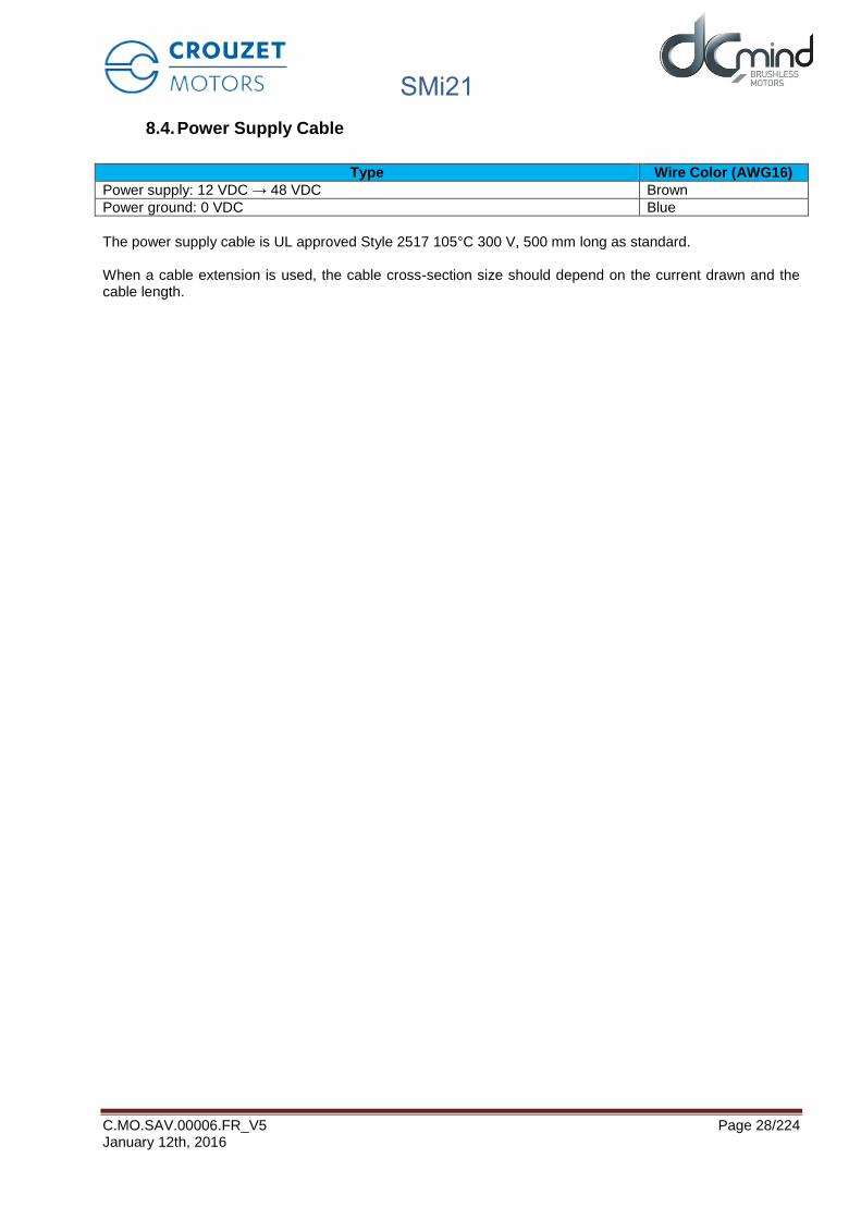
Type Wire Color (AWG16)
Power supply: 12 VDC → 48 VDC Brown
Power ground: 0 VDC Blue
The power supply cable is UL approved Style 2517 105°C 300 V, 500 mm long as standard.
When a cable extension is used, the cable cross-section size should depend on the current drawn and the cable length.

SMi21
C.MO.SAV.00006.FR_V5 Page 29/224 January 12th, 2016
9. MOTOR ELECTRICAL CONNECTION
9.1. Power Connection
We recommend grounding the motor housing.
Power connection diagram.
Figure 4
(1) Include capacitors to smooth out inrush currents. Recommended value 1000 µF/A drawn.
(2) Optional. The ballast circuit eliminates voltage surges produced when braking. See next section.
The product is not protected against polarity reversals on the power cable. A polarity reversal can damage the product irreversibly.
9.1.1. Ballast Circuit
When the motor brakes, the kinetic energy stored in the inertias during rotation is returned to the power supply and generates a voltage surge. This voltage surge can be destructive for the motor or for devices connected to the power supply. In the event of frequent braking, an external ballast circuit must be used. It is always necessary to conduct tests to check what size it should be.

SMi21
C.MO.SAV.00006.FR_V5 Page 30/224 January 12th, 2016
9.1.1.1. Proposed Ballast Circuit Diagram
The diagram below allows the braking energy to be dissipated into a resistor, thus limiting voltage surges at the motor terminals.
Figure 5
9.1.1.2. Determining the Size of the R12 Resistor (RBallast)
The higher the braking current, the lower the resistor value. Typical values are around several Ohms. With V the rotation speed in revolutions per minute and J the inertia in Kg.m², the energy E in Joules stored in the inertia is given by:
𝐸 =𝜋²
1800× 𝐽 × 𝑉²
If t is the braking duration in seconds, the power P1 dissipated during this time will be:
𝑃1 =𝐸
𝑡Note: The time t is set via the value of the deceleration ramps in the HMI.
If T is the time interval between 2 braking operations in seconds, the dissipated power P2 will be:
𝑃2 = 𝑃1
𝑇
The resistor should be large enough to dissipate the power P2 while tolerating peaks at P1.

SMi21
C.MO.SAV.00006.FR_V5 Page 31/224 January 12th, 2016
It should be noted however that this is a simplified and somewhat pessimistic calculation since it does not take account of the energy stored in the capacitors, nor that lost during friction, the gearbox, etc.
9.1.1.3. Voltage Breaking Capacity Selection
The voltage breaking capacity should be selected: - Depending on the power supply - Depending on the other devices connected to this power supply
If your power supply does not tolerate current feedback, place a diode in series upstream of the ballast circuit to protect it.
The voltage breaking capacity usually selected is between +10% and +20% of the supply voltage. E.g.: For 24 VDC the voltage breaking capacity would be 28 VDC.
List of components for the usual operating voltages:
Nominal voltage 12V 24V 32V 48V
Voltage breaking capacity
14V 28V 36V 52V
D1 SMBJ14A SMBJ28A SMBJ36A SMBJ54A
R13 0R 560R 0.5W 1K 1W 2K2 2W
R5 15K 1% 4K32 1% 3K09 1% 1K95 1%
9.1.2. EMC Protection
In order to ensure that the product is compatible with EMC standards IEC 61000-6-1, IEC 61000-6-2, IEC 61000-6-3, IEC 61000-6-4, we recommend:
- Connecting the motor to ground while limiting length of the grounding strip, - Adding capacitors on the main power supply.
We recommend 1000 µF per amp drawn.

SMi21
C.MO.SAV.00006.FR_V5 Page 32/224 January 12th, 2016
9.2. Protection
DANGER
PROTECTION The product has internal protection devices that switch off the motor power supply when activated. As the motor is no longer controlled, driving loads can decrease. • The system manufacturer is responsible for complying with allthe applicable safety rules in the event of product failure. Failure to comply with these precautions will result in death or serious injury.
9.2.1. Voltage Protection
The product incorporates protection against voltage surges and undervoltages.
Protection against voltage surges: The voltage surge threshold can be set in the HMI between 12 and 57 V (set at 57 V by default). When the supply voltage exceeds the threshold, the product automatically switches to ERROR mode. In ERROR mode the motor is no longer controlled. To reset the motor:
- The supply voltage must be at least 1 V below the threshold value. - The motor inputs must be set to STOP mode.
Protection against undervoltages: When the supply voltage falls below 8 V, the product automatically switches to ERROR mode. In ERROR mode the motor is no longer controlled. To reset the motor:
- The supply voltage must be higher than 9 V. - The motor inputs must be set to STOP mode.
9.2.2. Temperature Protection
The product incorporates temperature protection in the form of a temperature sensor on the motor pilot control card.
Temperature protection: When the internal temperature exceeds 110°C, the product automatically switches to ERROR mode. In ERROR mode the motor is no longer controlled. To reset the motor:
- The temperature must be less than 90°C. - The motor inputs must be set to STOP mode.
9.2.3. Current Limiting
The product incorporates internal current limiting. This limiting directly affects the motor in terms of hardware. This limiting automatically restricts the current to 17 A in the motor phases. If this limit is reached, it results in a loss of motor performance.
This product is not designed to operate continuously with this limiting (see the "Electrical Data" section).

SMi21
C.MO.SAV.00006.FR_V5 Page 33/224 January 12th, 2016
9.3. USB Connection
USB connection requires a type B micro-USB socket on the motor.
The cable must be less than 3 m long.
Possible cable part number: MOLEX 68784-0003.
Connection procedure
Carefully remove the black stopper from the motor to reveal the Micro USB-B connector. Thestopper has a retainer to keep it attached to the motor.
Figure 6 Figure 7
Insert the USB cable and install the drivers as instructed.
Take care never to touch the connector or contacts inside the motor with your fingers or any inappropriate object.
Once finished, it is essential to replace the stopper carefully, to maintain the motor seal and protect the connector from any contact.
Simply pressing your finger in the middle of the stopper will close it properly.
Figure 8

SMi21
C.MO.SAV.00006.FR_V5 Page 34/224 January 12th, 2016
Incorrect stopper fitting
Figure 9
Figure 10
Correct stopper fitting
Figure 11 Figure 12

SMi21
C.MO.SAV.00006.FR_V5 Page 35/224 January 12th, 2016
9.4. Input/Output Connection
9.4.1. Equivalent Input Diagram
NPN digital inputs
Figure 13
Analog/PWM/digital inputs
Figure 14

SMi21
C.MO.SAV.00006.FR_V5 Page 36/224 January 12th, 2016
9.4.2. Equivalent Output Diagram
PNP outputs with max. 50 mA open collector. Include a pull down resistor (recommended value 4.7 kΩ).
Figure 15
Caution: The output level is the same as the motor supply voltage: if V DC = 48V then Out1/Out2/Out3/Out4 = 48 V. In the event of rejection, this voltage increases accordingly, and can rise up to 57 V maximum (voltage threshold value).
If your application necessitates limiting the voltage value of these outputs, implement the diagram below.
Customer output (24 V)

SMi21
C.MO.SAV.00006.FR_V5 Page 37/224 January 12th, 2016
10. INSTALLATION OF THE DCMIND-SOFT HMI
10.1. Introduction
To configure motors in the SMi21 DCmind Brushless range, Crouzet provides a user-friendly HMI that is easy to use. By means of a communication interface, the HMI establishes the connection between the PC and the motor and can be used to configure the motor and adapt its operation to the application.
10.2. System Required
The HMI is compatible with the following operating systems:
- Windows XP Family & Professional (with Framework version 3.5 minimum: supplied on USB stick) - Windows Vista - Windows 7 (32 & 64-bit)
The HMI installation files are supplied on the USB stick in the programming kit and are available for download from the Internet at the following address: http://www.crouzet.com/
10.3. Installation of the USB Drivers
Run the "Driver Motor.exe" file in the "Driver" folder:
Figure 16
Figure 17

SMi21
C.MO.SAV.00006.FR_V5 Page 38/224 January 12th, 2016
10.4. Installation of the Crouzet DCmind-Soft HMI
Run the "Setup_DCmind_Soft_Vxxx.msi" file and follow the instructions:
N.B.: - When installing the "DCmind-Soft" HMI, check that Bluetooth is disabled on the PC.
- The USB drivers must always be installed upstream.
Figure 18: Steps 1 and 2
Figure 19: Steps 3 and 4
Once installation is complete, the PC software can be launched directly via the "DCmind-Soft" icon on the desktop.
Note: To uninstall the "DCmind-Soft" application, follow the standard Windows procedure:
- "Start" - "Control Panel" - "Add or Remove Programs" - "DCmind-Soft" - "Remove"

SMi21
C.MO.SAV.00006.FR_V5 Page 39/224 January 12th, 2016
Note: For PCs running Windows XP, the version of Framework may not be recent enough to be able to install the "DCmind-Soft" HMI. On launching the setup, the HMI automatically informs the user of this problem by displaying the following window:
Figure 20
We recommend that you download the latest available version of Framework from the Microsoft website. Should no internet connection be available, a minimum version of Framework is supplied on the USB stick in the programming kit.
To install version 3.5 of Framework supplied on the USB stick, run the "dotnetfx35.exe" file and follow the instructions:
Figure 21
Tick the box "I have read and accept the license terms", then press the "Install >" button.
Figure 22

SMi21
C.MO.SAV.00006.FR_V5 Page 40/224 January 12th, 2016
During installation, Windows tries to connect to the server to download the Framework multi-language package (this may take several minutes as 5 attempts are made to connect to the server). After 5 attempts, the software is installed directly via the setup supplied on the USB stick:
Figure 23
Figure 24
Once installation of Framework 3.5 is complete, try again to install the "DCmind-Soft" HMI, referring to the "Installation of the Crouzet DCmind-Soft HMI" section in this document.

SMi21
C.MO.SAV.00006.FR_V5 Page 41/224 January 12th, 2016
10.5. Description of the Main Window
Once all the installations are complete (drivers + HMI), connect the motor to the PC and launch the HMI by double-clicking on the icon below:
Figure 25
The HMI home page appears:
Figure 26
Application programs:
The application programs are grouped together with similar applications (valve, conveyor belt,machine, etc.).
They enable quick start-up with completion of just a few key application values.
Each application program is based on a preconfigured expert program.After testing the motor a few times in the application, the user can refine the motor operation byaccessing all the adjustment parameters via the expert program linked to the application programand changing the pre-filled values.
Expert programs:
The expert programs are grouped together with similar programs (P1xx, P2xx, etc position control,V1xx, V2xx speed control, C1xx, C2xx torque control).
These are generic programs, not specific to any application. They can be used to access all theoptions and settings.
Main menu bar Contextual help window
Application Program selection
Expert Program selection
Displays the various application programs in the form of icons
Displays the various expert programs in the form of icons

SMi21
C.MO.SAV.00006.FR_V5 Page 42/224 January 12th, 2016
They can be used directly, without going via the "application program" step and they offer a widerchoice of uses.
The contextual help window gives a description of the selected application when you hover over it with the mouse cursor.
Note: DCmind-Soft is constantly being improved. The latest available update can be downloaded from our website http://www.crouzet.com/
Description of the tabs on the main menu bar:
Figure 27
"Motor Information" window
Figure 28
Language: HMI language selection Bootloader: Board firmware update
Open: Loads a parameter file Save As: Saves a parameter file Exit: Closes the HMI
Motor Information: Can be used to find out information about the motor when it is connected

SMi21
C.MO.SAV.00006.FR_V5 Page 43/224 January 12th, 2016
The "Help" tab contains the SMi21 DCmind Brushless motors user manual in .pdf format.
10.6. Motor Connection
To connect the motor, link the motor and the PC using the USB B to USB A micro cable (supplied in the programming kit), power up the motor and click on "Motor Connection" in the main menu bar. The following window appears:
Figure 29
Click the "Autodetect button to start the automatic motor search. If a motor is connected to the PC, it is automatically detected and the following window appears:
Figure 30
Figure 31
COM port on which the motor has been detected
Link baud rate

SMi21
C.MO.SAV.00006.FR_V5 Page 44/224 January 12th, 2016
Click "OK", the motor is now connected and ready to be used.
If "Motor not detected" appears in the information window, check that the motor is correctly supplied with power, the micro USB B to USB A cable is plugged in correctly and repeat the procedure.
10.7. Updating the Firmware
To update the version of the software embedded in the motor, a bootloader is used via USB communication. This operation can only be performed by advanced users, as if done incorrectly this could result in the product not working.
Power up the motor and click "Bootloader" in the main menu bar (entire memory completely rewritten), the following window appears:
Figure 32
A warning message appears asking to confirm the firmware update request and to avoid any incorrect action:
Figure 33
To start the update, click "Yes" and select the .hex program supplied by CROUZET:
Click this button to completely rewrite the program.

SMi21
C.MO.SAV.00006.FR_V5 Page 45/224 January 12th, 2016
Figure 34
Click the "Open" button, updating begins:
Figure 35
When the update is complete, the following window appears, meaning that loading has been successful:
.hex program supplied by CROUZET
Location of the .hex file being loaded.
Loading progress bar.

SMi21
C.MO.SAV.00006.FR_V5 Page 46/224 January 12th, 2016
Figure 36
11. APPLICATION PROGRAMS
11.1. Description
Select an application group from the list of application programs, then one of the icons corresponding to your application.
Figure 37
Figure 38

SMi21
C.MO.SAV.00006.FR_V5 Page 47/224 January 12th, 2016
Figure 39

SMi21
C.MO.SAV.00006.FR_V5 Page 48/224 January 12th, 2016
11.2. Description of the Monitoring Part
The monitoring part of the HMI is common to all the expert and application program tabs.
Figure 40
This zone uses graphic icons to indicate the type of program I/O used (in this case 4 digital inputs, 2 analog setpoint inputs, 2 PWM outputs and 2 digital outputs).
This zone describes the status of the connection between the HMI and the motor (green for connected and red for not connected).It gives in real time (once a second) the value of the various measurements taken on the motor (voltage, temperature, speed, position and torque).
States of the various program digital I/O (green for active and blue for inactive). For the analog setpoints, the user can display their value (rpm, rpm/sec, mN.m, etc.) on the IN5 and IN6 dial faces. The type of error detected can be viewed on this tab. PWM/Pulse or Frequency type outputs are not included in this tab.

SMi21
C.MO.SAV.00006.FR_V5 Page 49/224 January 12th, 2016
11.3. "Valve" Group
11.3.1. "Valve 4 positions" Application Program
Figure 41
The "Valve 4 positions" application program invokes the P101 expert program. The user can switch to this expert mode at any time to access all the settings by clicking the "Expert Mode" button. The values preset in application mode will be loaded directly in expert mode.It is then impossible to return to this application program.
The user can press the "STOP" button at any time to stop the application quickly. To restart the motor, the program needs to be reloaded. Once the settings are complete, press the "Load Program" button to configure the motor.
Note: Each time you power ON the power supply or a program is loaded, it is necessary to perform the homing sequence.
11.3.1.1. Inputs/Outputs Configuration
Refer to the "I/O Connection" section.
Inputs:
IN1: If 0 → No position setpoint, if 1 → Setpoint = "Position 1" Parameter
IN2: If 0 → No position setpoint, if 1 → Setpoint = "Position 2" Parameter
IN3: If 0 → No position setpoint, if 1 → Setpoint = "Position 3" Parameter
IN4: If 0 → No position setpoint, if 1 → Setpoint = "Position 4" Parameter
IN5: If 0 → No action, if 1 → Launch homing phase
IN6: If 0 → Stop, if 1 → Run
N.B.: if more than 1 input IN1 to IN4 is activated at the same time, the motor switches to stop mode.
Input connections
Output connections

SMi21
C.MO.SAV.00006.FR_V5 Page 50/224 January 12th, 2016
Outputs: Don't forget to fit the pull-down resistors on each of the outputs.
OUT1: If 0 → setpoint position not reached, if 1 → setpoint position reached.
OUT2: If 0 → homing phase complete, if 1 → homing phase in progress or not performed.
OUT3: If 0 → motor stopped, if 1 → motor running.
OUT4: If 0 → no error, if 1 → error detected.
11.3.1.2. Application Settings
The user can give a 4-character name in "Project name" which is stored in the motor and appears in the"Motor Information" window.
If it has been saved on the PC by the user, this name is used by default. For more details, see the"Saving Parameters" paragraph.
The "Number of rotation(s) to close the valve" and "Mechanical ratio between the motor and the valve"parameters are used to calculate the application total stroke in number of motor revolutions:
𝑇𝑜𝑡𝑎𝑙 𝑐𝑜𝑢𝑟𝑠𝑒 [𝑅𝑜𝑡𝑎𝑡𝑖𝑜𝑛 𝑚𝑜𝑡𝑜𝑟] = 𝑁𝑏 𝑜𝑓 𝑟𝑜𝑡𝑎𝑡𝑖𝑜𝑛𝑟𝐶𝑙𝑜𝑠𝑖𝑛𝑔 𝑣𝑎𝑙𝑣𝑒 × 𝜂 𝑉𝑎𝑣𝑒𝑠 𝑣𝑠 𝑀𝑜𝑡𝑜𝑟
The "Time to realize the total stroke" parameter is used to calculate the motor speed of rotation during thepositioning phases:
𝑀𝑜𝑡𝑜𝑟 𝑠𝑝𝑒𝑒𝑑 [𝑅𝑃𝑀] = 𝑇𝑜𝑡𝑎𝑙 𝑐𝑜𝑢𝑟𝑠𝑒 [𝑅𝑜𝑡𝑎𝑡𝑖𝑜𝑛𝑚𝑜𝑡𝑜𝑟] × 60
𝑇𝑖𝑚𝑒𝑠𝑡𝑜𝑡𝑎𝑙 𝑐𝑜𝑢𝑟𝑠𝑒 [𝑠𝑒𝑐]
The calculated value is given for information in the grayed-out box.
The motor speed of rotation during the mechanical stop search phase (homing) is determined as follows:
𝐻𝑜𝑚𝑖𝑛𝑔 𝑠𝑝𝑒𝑒𝑑 [𝑅𝑃𝑀] =𝑀𝑜𝑡𝑜𝑟 𝑠𝑝𝑒𝑒𝑑 [𝑅𝑃𝑀]
5
11.3.1.3. Motor Configuration
Used to configure the mechanical stop search phase (homing) by setting the "Homing torque" and thedirection of valve closing.
The nominal and maximum torques in the motor are determined from the "Homing torque" valueas follows:
𝑁𝑜𝑚𝑖𝑛𝑎𝑙 𝑡𝑜𝑟𝑞𝑢𝑒 = 𝐻𝑜𝑚𝑖𝑛𝑔 𝑡𝑜𝑟𝑞𝑢𝑒
𝑇𝑜𝑟𝑞𝑢𝑒 𝑀𝑎𝑥𝑖 = 2 × 𝐻𝑜𝑚𝑖𝑛𝑔 𝑡𝑜𝑟𝑞𝑢𝑒
For information, the maximum torque value seen by the valve during operation is given in the grayed-outbox.
11.3.1.4. Valve Positioning
The user has the option of setting 4 setpoint position parameters as a percentage of valve opening.
By default, position 1 corresponds to detection of the mechanical stop (valve closed). If the user wishes toadd an offset to avoid mechanical shocks during valve closing, he should change the "Position 1"parameter accordingly.
By default, position 4 corresponds to the application total stroke (valve open).
For information, all 4 positions are given in number of pulses (4096 pulses per motor revolution) in the
grayed-out boxes.

SMi21
C.MO.SAV.00006.FR_V5 Page 51/224 January 12th, 2016
11.3.2. "Valve 30 positions" Application Program with 1 Mechanical Stop
Figure 42
The "Valve 30 positions" application program invokes the P111 expert program. The user can switch to this expert mode at any time to access all the settings by clicking the "Expert Mode" button. The values preset in application mode will be loaded directly in expert mode.It is then impossible to return to this application program.
The user can press the "STOP" button at any time to stop the application quickly. To restart the motor, the program needs to be reloaded. Once the settings are complete, press the "Load Program" button to configure the motor.
Note: Each time you power ON the power supply or a program is loaded, it is necessary to perform the homing sequence.
11.3.2.1. Inputs/Outputs Configuration
Refer to the "I/O Connection" section.
Inputs:
IN1 to IN5: 32 possible combinations:- IN1 = IN2 = IN3 = IN4 = IN5 = 0 → Stop. - IN1 = 1, all 4 others = 0 → Launch homing phase. - The other 30 combinations correspond to the 30 position setpoints.
IN6: Not used.
Input connections
Output connections

SMi21
C.MO.SAV.00006.FR_V5 Page 52/224 January 12th, 2016
Outputs: Don't forget to fit the pull-down resistors on each of the outputs.
OUT1: If 0 → setpoint position not reached, if 1 → setpoint position reached.
OUT2: If 0 → homing phase complete, if 1 → homing phase in progress or not performed.
OUT3: If 0 → motor stopped, if 1 → motor running.
OUT4: If 0 → no error, if 1 → error detected.
11.3.2.2. Application Settings
The user can give a 4-character name in "Project name" which is stored in the motor and appears in the"Motor Information" window.
If it has been saved on the PC by the user, this name is used by default. For more details, see the"Saving Parameters" paragraph.
The "Number of rotation(s) to close the valve" and "Mechanical ratio between the motor and the valve"parameters are used to calculate the application total stroke in number of motor revolutions:
𝑇𝑜𝑡𝑎𝑙𝑒 𝑐𝑜𝑢𝑟𝑠𝑒 [𝑅𝑜𝑡𝑎𝑡𝑖𝑜𝑛𝑚𝑜𝑡𝑜𝑟] = 𝑁𝑏 𝑟𝑜𝑡𝑎𝑡𝑖𝑜𝑛 𝑐𝑙𝑜𝑠𝑖𝑛𝑔 𝑣𝑎𝑙𝑣𝑒 × 𝜂 𝑉𝑎𝑙𝑣𝑒 𝑣𝑠 𝑀𝑜𝑡𝑜𝑟
The "Time to realize the total stroke" parameter is used to calculate the motor speed of rotation during thepositioning phases:
𝑀𝑜𝑡𝑜𝑟 𝑠𝑝𝑒𝑒𝑑 [𝑅𝑃𝑀] =𝑇𝑜𝑡𝑎𝑙𝑒 𝑐𝑜𝑢𝑟𝑠𝑒[𝑟𝑜𝑡𝑎𝑡𝑖𝑜𝑛 𝑚𝑜𝑡𝑜𝑟] × 60
𝑇𝑖𝑚𝑒𝑠𝑇𝑜𝑡𝑎𝑙𝑒 𝑐𝑜𝑢𝑟𝑠𝑒 [𝑠𝑒𝑐]
The calculated value is given for information in the grayed-out box.
The motor speed of rotation during the mechanical stop search phase (homing) is determined as follows:
𝐻𝑜𝑚𝑖𝑛𝑔 𝑠𝑝𝑒𝑒𝑑[𝑅𝑃𝑀] =𝑀𝑜𝑡𝑜𝑟 𝑠𝑝𝑒𝑒𝑑 [𝑅𝑃𝑀]
5
11.3.2.3. Motor Configuration
Used to configure the mechanical stop search phase (homing) by setting the "Homing torque" and thedirection of valve closing.
The nominal and maximum torques in the motor should be determined from the "Homing torque" valueas follows:
𝑁𝑜𝑚𝑖𝑛𝑎𝑙 𝑡𝑜𝑟𝑞𝑢𝑒 = 𝐻𝑜𝑚𝑖𝑛𝑔 𝑡𝑜𝑟𝑞𝑢𝑒
𝑀𝑎𝑥𝑖 𝑡𝑜𝑟𝑞𝑢𝑒 = 2 × 𝐻𝑜𝑚𝑖𝑛𝑔 𝑡𝑜𝑟𝑞𝑢𝑒
For information, the maximum torque value seen by the valve during operation is given in the grayed-outbox.
11.3.2.4. Position Table
The user is not able to change the position setpoints, they will automatically be defined with between 2and 30 equal positions, according to the defined total stroke and the "Number of positions" parameter. Tochange them, you need to change to "Expert Mode".
By default, position 1 corresponds to detection of the mechanical stop (valve closed).
By default, the last position corresponds to the application total stroke (valve open).

SMi21
C.MO.SAV.00006.FR_V5 Page 53/224 January 12th, 2016
For information, the position setpoints are given in number of valve rotations and number of pulses (4096pulses per motor revolution).

SMi21
C.MO.SAV.00006.FR_V5 Page 54/224 January 12th, 2016
11.4. "Conveyor Belt" Group
11.4.1. "Conveyor Belt 0-10V" Application Program
Figure 43
The "Conveyor Belt 0-10V" application program invokes the V101 expert program. The user can switch to this expert mode at any time to access all the settings by clicking the "Expert Mode" button. The values preset in application mode will be loaded directly in expert mode.It is then impossible to return to this application program.
The user can press the "STOP" button at any time to stop the application quickly. To restart the motor, the program needs to be reloaded.
Once the settings are complete, press the "Load Program" button to configure the motor.
11.4.1.1. Inputs/Outputs Configuration
Refer to the "I/O Connection" section.
Inputs:
IN1: If 0 → Stop, if 1 → Run
IN2: If 0 → motor running in reverse (CCW), if 1 → motor running forward (CW)
IN3: If IN3 = 1 and IN1 = 1 and IN6 = 0, application of a 150 mNm holding torque.
IN4: If 0 → no action, if 1 → Quick start by short-circuiting the coils. This action takes priority over theother commands.
IN5: 0-10 V control. Sets the motor acceleration and deceleration. 40,000 rpm/sec for 0 V (maximumacceleration) and 100 rpm/sec for 10 V.
Input connections
Output connections

SMi21
C.MO.SAV.00006.FR_V5 Page 55/224 January 12th, 2016
IN6: 0-10 V control. Sets the speed setpoint. 0 V for 0 rpm and 10 V for the maximum motor speed
defined by the user.
Outputs: Don't forget to fit the pull-down resistors on each of the outputs.
OUT1: Provides information on the motor speed value in PWM. Cyclical ratio = 0% → speed = 0 rpm Cyclical ratio = 100% → speed = maximum speed.
OUT2: Provides information on the real torque value in PWM. Cyclical ratio = 0% → torque = 0 mNm Cyclical ratio = 100% → torque = 1 Nm.
OUT3: If 0 → motor running, if 1 → motor stopped.
OUT4: If 0 → error detected, if 1 → no error.
11.4.1.2. Application Settings
The user can give a 4-character name in "Project name" which is stored in the motor and appears in the"Motor Information" window.
If it has been saved on the PC by the user, this name is used by default. For more details, see the"Saving Parameters" paragraph.
The maximum motor speed corresponding to a voltage of 10 V is calculated as follows:
𝑆𝑒𝑡𝑝𝑜𝑖𝑛𝑡 𝑚𝑜𝑡𝑜𝑟 𝑠𝑝𝑒𝑒𝑑10𝑉[𝑅𝑃𝑀] =𝑀𝑎𝑥 𝑠𝑝𝑒𝑒𝑑 𝑇𝑎𝑝𝑖𝑠 [𝑚. 𝑠−1] × 60
𝑆𝑝𝑒𝑒𝑑 𝑠𝑡𝑒𝑝 [𝑚. 𝑡𝑟−1]
The calculated value is given for information in the grayed-out box.

SMi21
C.MO.SAV.00006.FR_V5 Page 56/224 January 12th, 2016
11.4.2. "Conveyor Belt PWM" Application Program
Figure 44
The "Conveyor Belt PWM" application program invokes the V101 expert program. The user can switch to this expert mode at any time to access all the settings by clicking the "Expert Mode" button. The values preset in application mode will be loaded directly in expert mode.It is then impossible to return to this application program.
The user can press the "STOP" button at any time to stop the application quickly. To restart the motor, the program needs to be reloaded.
Once the settings are complete, press the "Load Program" button to configure the motor.
11.4.2.1. Inputs/Outputs Configuration
Refer to the "I/O Connection" section.
Inputs:
IN1: If 0 → Stop, if 1 → Run
IN2: If 0 → motor running in reverse (CCW), if 1 → motor running forward (CW)
IN3: If IN3 = 1 and IN1 = 1 and IN6 = 0, application of a 150 mNm holding torque.
IN4: If 0 → no action, if 1 → Quick start by short-circuiting the coils. This action takes priority over theother commands.
IN5: PWM control. Sets the motor acceleration and deceleration. 40,000 rpm/sec for 0% PWM(maximum acceleration) and 100 rpm/sec for 100% PWM.
IN6: PWM control. Sets the speed setpoint. 0% PWM for 0 rpm and 100% PWM for the maximummotor speed defined by the user.
Input connections
Output connections

SMi21
C.MO.SAV.00006.FR_V5 Page 57/224 January 12th, 2016
Outputs: Don't forget to fit the pull-down resistors on each of the outputs.
OUT1: Provides information on the motor speed value in PWM. Cyclical ratio = 0% → speed = 0 rpm Cyclical ratio = 100% → speed = maximum speed.
OUT2: Provides information on the real torque value in PWM. Cyclical ratio = 0% → torque = 0 mNm Cyclical ratio = 100% → torque = 1 Nm.
OUT3: If 0 → motor running, if 1 → motor stopped.
OUT4: If 0 → error detected, if 1 → no error.
11.4.2.2. Application Settings
The user can give a 4-character name in "Project name" which is stored in the motor and appears in the"Motor Information" window.
If it has been saved on the PC by the user, this name is used by default. For more details, see the"Saving Parameters" paragraph.
The maximum motor speed corresponding to a PWM signal with 100% cyclical ratio is calculated asfollows:
𝑆𝑒𝑡𝑝𝑜𝑖𝑛𝑡 𝑚𝑜𝑡𝑜𝑟 𝑠𝑝𝑒𝑒𝑑100% 𝑃𝑊𝑀[𝑅𝑃𝑀] =𝑀𝑎𝑥 𝑠𝑝𝑒𝑒𝑑 [𝑚. 𝑠−1] × 60
𝑆𝑝𝑒𝑒𝑑 𝑠𝑡𝑒𝑝 [𝑚. 𝑡𝑟−1]
The calculated value is given for information in the grayed-out box.

SMi21
C.MO.SAV.00006.FR_V5 Page 58/224 January 12th, 2016
11.4.3. « Conveyor with stop on detection » Application program
Figure 45
The « Conveyor belt with stop on detection » application program invokes the V202 expert program. The user can switch to this expert mode at any time to access all the settings by clicking the "Expert Mode" button. The values preset in application mode will be loaded directly in expert mode.It is then impossible to return to this application program.
The user can press the "STOP" button at any time to stop the application quickly. To restart the motor, the program needs to be reloaded.
Once settings are complete, press the "Load Program" button to configure the motor.
11.4.3.1. Inputs/Outputs Configuration
Refer to the "I/O Connection" section.
Inputs: (0 = no voltage applied; 1 = voltage applied on the input)
IN1 : « ON/OFF » 0 → Stop, 1 → Run
IN2 : « Usual belt direction » 0 → Direction from program setting 1 → Direction inverted
Note: this input is useful when a same program setting is needed for conveyors having to run in opposite directions.
IN3 : « Reverse direction » 0 → No reverse 1 → Reverses and inhibits IN4
IN4 : « Sensor » 0 → Nothing detected 1 → Stop required (if IN3 = 0)
IN5 : « Speed » Analog input (0/10V or PWM) → Speed setting
IN6 : « Position » Analog input (0/10V or PWM) → Stop distance setting
Input connecting
Output connecting

SMi21
C.MO.SAV.00006.FR_V5 Page 59/224 January 12th, 2016
Outputs: Don't forget to fit the pull-down resistors on each of the outputs.
OUT1 : Target0 : Stop position not reached 1 : Stop position reached
OUT2 : Direction.0 : Motor CCW (counter clock wise) 1 : Motor CW (clock wise)
OUT3 : Run0 : No run 1 : Motor running
OUT4 : Error :0: No error detected 1: Error detected.
11.4.3.2. Application Settings
The user can give a 4-character name in "Project name" which is stored in the motor and appears in the"Motor Information" window.
If it has been saved on the PC by the user, this name is used by default. For more details, see the"Saving Parameters" paragraph.
Parameters « Max. belt speed » and « Mechanical ratio » allow to define the maximum motor speed at10V input.
Maximum motor speed is calculated as following :
𝑀𝑜𝑡𝑜𝑟 𝑠𝑝𝑒𝑒𝑑10𝑉[𝑅𝑃𝑀] =𝑀𝑎𝑥 𝑏𝑒𝑙𝑡 𝑠𝑝𝑒𝑒𝑑 [𝑚. 𝑠−1] × 60
𝑀𝑒𝑐ℎ𝑎𝑛𝑖𝑐𝑎𝑙 𝑟𝑎𝑡𝑖𝑜 [𝑚. 𝑡𝑟−1]
This value is indicated in the grey box for information.
Belt conveyor stop distance is calculated as following :
Parameters « Max. stop distance » and « Mechanical ratio » are used to calculate the maximum rotationof the motor in number of pulses (4096 pulses represent one motor turn).
𝑀𝑜𝑡𝑜𝑟 𝑝𝑢𝑙𝑠𝑒𝑠10𝑉[𝑃𝑢𝑙𝑠𝑒𝑠] =𝑀𝑎𝑥. 𝑠𝑡𝑜𝑝 𝑑𝑖𝑠𝑡𝑎𝑛𝑐𝑒 [𝑐𝑚] × 4096
100 ∗ 𝑀𝑒𝑐ℎ𝑎𝑛𝑖𝑐𝑎𝑙 𝑟𝑎𝑡𝑖𝑜 [𝑚. 𝑡𝑟−1]
This value is indicated in the grey box for information.
« Motor direction » area allows to define the motor direction by defect (when IN2 = 0).Conveyor belt manufacturers ask for good use, that conveyor’s motor pulls the belt which brings objects(not push).
« Command” area allows to define which signal type will be used for IN5 and IN6.
Option “Via PLC” allows to precise if the “sensor” input is driven by PLC (if selected) or directly by theobject’s sensor (if not selected).When “Via PLC” is not selected, motor memorizes the “sensor” detections and goes to stop position evenif the detected object exceeds the detector. To restart the conveyor in speed, an OFF/ON action on IN1has to be done.
Parameter « minimum pulse duration » allows to filter IN4 sensor input signal. The signal has to exceedthis time before to be taken in count.

SMi21
C.MO.SAV.00006.FR_V5 Page 60/224 January 12th, 2016
11.5. "Machine" Group
11.5.1. "Worm Gear" Application Program
Figure 46
The "Worm Gear" application program uses a preset P111 expert program. The user can switch to this expert mode at any time to access all the settings by clicking the "Expert Mode" button. The values preset in application mode will be loaded directly in expert mode.It is then impossible to return to this application program.
The user can press the "STOP" button at any time to stop the application quickly. To restart the motor, the program needs to be reloaded. Once the settings are complete, press the "Load Program" button to configure the motor.
Note: Each time you power ON the power supply or a program is loaded, it is necessary to perform the homing sequence.
11.5.1.1. Inputs/Outputs Configuration
Refer to the "I/O Connection" section.
Inputs:
IN1 to IN5: 32 possible combinations:- IN1 = IN2 = IN3 = IN4 = IN5 = 0 → Stop - IN1 = 1, all 4 others = 0 → Launch homing phase - The other 30 combinations correspond to the 30 position setpoints
IN6: Switch limit input if « switch » is selected as “type of stop”
Input connections
Output connections

SMi21
C.MO.SAV.00006.FR_V5 Page 61/224 January 12th, 2016
Outputs: Don't forget to fit the pull-down resistors on each of the outputs.
OUT1: If 0 → setpoint position not reached, if 1 → setpoint position reached.
OUT2: If 0 → homing phase complete, if 1 → homing phase in progress or not performed.
OUT3: If 0 → motor stopped, if 1 → motor running.
OUT4: If 0 → no error, if 1 → error detected.
11.5.1.2. Initialization Phase
The user can give a 4-character name in "Project name" which is stored in the motor and appears in the"Motor Information" window.
If it has been saved on the PC by the user, this name is used by default. For more details, see the"Saving Parameters" paragraph.
Select the type of stop, either "Mechanical" if the stop is achieved by detection of an obstacle on the
application, or "Switch" if a limit switch is used in the application.
Define the motor direction of rotation used to reach the stop selected above (forward (CW) rotation bydefault).
To protect the application and prevent the mechanical stop being reached each time it returns to positionzero, a position offset (in mm) can be set between the mechanical stop and position 1 corresponding tothe application reference.
11.5.1.3. Application Settings
To determine the maximum operating speed during the positioning phases, the user should enter themaximum linear speed in mm/s and the "Step of the screw" and "Mechanical ratio between the motor andthe screw" adjustment parameters are used to obtain a motor speed of rotation according to the formulabelow:
𝑀𝑜𝑡𝑜𝑟 𝑠𝑝𝑒𝑒𝑑 [𝑅𝑃𝑀] =𝐿𝑖𝑛𝑒𝑎𝑟 𝑠𝑝𝑒𝑒𝑑 [𝑚𝑚/𝑠] × 𝑠𝑡𝑒𝑝𝑅𝑒𝑑𝑢𝑐𝑡𝑖𝑜𝑛 × 60
𝑆𝑡𝑒𝑝𝑠𝑐𝑟𝑒𝑤 [𝑚𝑚/𝑟𝑜𝑡𝑎𝑡𝑖𝑜𝑛]
The motor speed of rotation during the mechanical stop search phase (homing) is determined as follows:
𝐻𝑜𝑚𝑖𝑛𝑔 𝑠𝑝𝑒𝑒𝑑 [𝑅𝑃𝑀] =𝑀𝑜𝑡𝑜𝑟 𝑠𝑝𝑒𝑒𝑑 [𝑅𝑃𝑀]
5
11.5.1.4. Motor Configuration
To determine the nominal torque during operation, the user should enter the maximum thrust for hisapplication in Newtons and the "Step of the screw" and "Mechanical ratio between the motor and thescrew" adjustment parameters are used to obtain a nominal motor torque using the following formula:
𝑀𝑜𝑡𝑜𝑟 𝑡𝑜𝑟𝑞𝑢𝑒 [𝑚𝑁. 𝑚] =1
2𝜋×
𝑃𝑢𝑠ℎ𝑖𝑛𝑔 [𝑁] × 𝑆𝑡𝑒𝑝𝑠𝑐𝑟𝑒𝑤[𝑚𝑚/𝑡𝑜𝑢𝑟]
𝑆𝑡𝑒𝑝𝑅𝑒𝑑𝑢𝑐𝑡𝑖𝑜𝑛
The homing and maximum torques for detecting the mechanical stop in the motor are determined fromthe "Motor Torque" value defined above as follows:
𝐻𝑜𝑚𝑖𝑛𝑔 𝑡𝑜𝑟𝑞𝑢𝑒 = 𝑀𝑜𝑡𝑜𝑟 𝑡𝑜𝑟𝑞𝑢𝑒

C.MO.SAV.00006.FR_V5 Page 62/224 January 12th, 2016
SMi21
𝑀𝑎𝑥𝑖 𝑡𝑜𝑟𝑞𝑢𝑒 = 2 × 𝑀𝑜𝑡𝑜𝑟 𝑡𝑜𝑟𝑞𝑢𝑒
11.5.1.5. Position Table
The user is not able to enter the 2 to 30 position setpoints himself, they are automatically defined withbetween 2 and 30 equidistant positions, according to the defined total stroke "Total stroke length" and the"Number of positions" parameter.
Position 1 corresponds to detection of the mechanical stop (as close as possible to the offset).
The last position corresponds to the application total stroke.
In the table, the position setpoints are given in mm.

SMi21
C.MO.SAV.00006.FR_V5 Page 63/224 January 12th, 2016
11.5.2. "Worm Gear (Proportional)" Application Program
Figure 47
The "Worm Gear (Proportional)" application program uses the P201 expert program. The user can switch to this expert mode at any time to access all the settings by clicking the "Expert Mode" button. The values preset in application mode will be loaded directly in expert mode.It is then impossible to return to this application program.
The user can press the "STOP" button at any time to stop the application quickly. To restart the motor, the program needs to be reloaded. Once the settings are complete, press the "Load Program" button to configure the motor.
Note: Each time you power ON the power supply or a program is loaded, it is necessary to perform the homing sequence
11.5.2.1. Inputs/Outputs Configuration
Refer to the "I/O Connection" section.
Inputs:
IN1 and IN2 : 4 possible combinations :- [IN1-IN2] = [00] → Stop and error reset - [IN1-IN2] = [10] → Homing phase - [IN1-IN2] = [01] → Maintain actual position - [IN1-IN2] = [11] → Go to required position
IN3 : Switch limit input if « switch » is selected as “type of stop”
IN4 : High speed (if 0) or low speed (if 1) selection
IN5 : Proportional position setting – Coarse tuning
IN6 : Proportional position setting – Thin tuning
Input connections
Output connections

SMi21
C.MO.SAV.00006.FR_V5 Page 64/224 January 12th, 2016
Outputs: Don't forget to fit the pull-down resistors on each of the outputs.
OUT1: Provides information on the motor speed value in PWM. Cyclical ratio = 0% → speed = 0 rpm Cyclical ratio = 100% → speed = 4000 rpm.
OUT2: Provides information on the real torque value in PWM. Cyclical ratio = 0% → torque = 0 mNm Cyclical ratio = 100% → torque = maximum torque.
OUT3: If 0 → motor running, if 1 → motor stopped.
OUT4: If 0 → error detected, if 1 → no error.
11.5.2.2. Initialization Phase
The user can give a 4-character name in "Project name" which is stored in the motor and appears in the"Motor Information" window.
If it has been saved on the PC by the user, this name is used by default. For more details, see the"Saving Parameters" paragraph.
Select the type of stop, either "Mechanical" if the stop is achieved by detection of an obstacle on the
application, or "Switch" if a limit switch is used in the application.
Define the motor direction of rotation used to reach the stop selected above (forward (CW) rotation bydefault).
To protect the application and prevent the mechanical stop being reached each time it returns to positionzero, a position offset (in mm) can be set between the mechanical stop and position 1 corresponding tothe application reference.
11.5.2.3. Application Settings
To determine the maximum operating speed during the positioning phases, the user should enter themaximum linear speed in mm/s and the "Step of the screw" and "Mechanical ratio between the motor andthe screw" adjustment parameters are used to obtain a motor speed of rotation according to the formulabelow:
𝑀𝑎𝑥𝑖𝑚𝑢𝑚 𝑠𝑝𝑒𝑒𝑑 [𝑅𝑃𝑀] =𝑀𝑎𝑥𝑖𝑚𝑢𝑚 𝑙𝑖𝑛𝑒𝑎𝑟 𝑠𝑝𝑒𝑒𝑑 [𝑚𝑚/𝑠] × 𝑠𝑡𝑒𝑝𝑅𝑒𝑑𝑢𝑐𝑡𝑖𝑜𝑛 × 60
𝑆𝑡𝑒𝑝𝑠𝑐𝑟𝑒𝑤 [𝑚𝑚/𝑟𝑜𝑡𝑎𝑡𝑖𝑜𝑛]
By activating the digital input 4 (IN4 = 1), the user selects the low speed profile :
𝐿𝑜𝑤 𝑠𝑝𝑒𝑒𝑑 [𝑅𝑃𝑀] =𝑀𝑎𝑥𝑖𝑚𝑢𝑚 𝑠𝑝𝑒𝑒𝑑 [𝑅𝑃𝑀]
5
The motor speed of rotation during the mechanical stop search phase (homing) is determined as follows:
𝐻𝑜𝑚𝑖𝑛𝑔 𝑠𝑝𝑒𝑒𝑑 [𝑅𝑃𝑀] =𝑀𝑎𝑥𝑖𝑚𝑢𝑚 𝑠𝑝𝑒𝑒𝑑 [𝑅𝑃𝑀]
5
NB: Motor speed is restricted to max. 4000rpm in this program. If this value is exceeded, the writing becomes red colored and the loading of the parameters becomes impossible. It is strongly advised to check motor specifications before to configuring the application.

SMi21
C.MO.SAV.00006.FR_V5 Page 65/224 January 12th, 2016
11.5.2.4. Motor Configuration
To determine the maximum torque during operation, the user should enter the maximum thrust for hisapplication in Newtons and the "Step of the screw" and "Mechanical ratio between the motor and thescrew" and “Mechanical system efficiency” adjustment parameters are used to obtain a maximum motortorque using the following formula:
𝑀𝑎𝑥𝑖𝑚𝑢𝑚 𝑡𝑜𝑟𝑞𝑢𝑒 [𝑚𝑁. 𝑚] =1
2𝜋×
𝑃𝑢𝑠ℎ𝑖𝑛𝑔 [𝑁] × 𝑆𝑡𝑒𝑝𝑠𝑐𝑟𝑒𝑤[𝑚𝑚/𝑡𝑜𝑢𝑟]
𝑆𝑡𝑒𝑝𝑅𝑒𝑑𝑢𝑐𝑡𝑖𝑜𝑛
× 2
𝑁𝑜𝑚𝑖𝑛𝑎𝑙 𝑡𝑜𝑟𝑞𝑢𝑒 =𝑀𝑎𝑥𝑖𝑚𝑢𝑚 𝑡𝑜𝑟𝑞𝑢𝑒
2
To detect the mechanical end stop, the homing torque is automatically set to be equal to nominal torque.
NB : The max. torque has to don’t be higher than 1000 mNm. If this value is exceeded, the writing becomes red colored and the loading of the parameters becomes impossible. The real maximum torque value is limited per motor characteristics. It is strongly advised to check motor specifications before to configuring the application.
11.5.2.5. Position setpoint
The user indicates the total stroke in mm of the application : parameter « Total stroke length ».
The full stroke is achieved when both setpoints (IN5 and IN6) are at 10V. To travel this distance, the
settings are distributed as follows:
o Coarse setting : Input IN5 allows to travel 63/64th of the « total stroke length »
o Thin setting : Input IN6 allows to travel 1/64th of the « total stroke length »
The resolution of each of the two inputs IN5 and IN6 is given as an indication in the gray boxes in the
« Position table – Input 5 and input 6 scale » zone :
o Distance equivalent to an applied voltage of 1V
o Distance equivalent to an applied voltage of 0,01V (resolution of the system)
Example : For a «Total stroke length » = 300 mm :
→ Input IN5 allows to travel: 𝑆𝑡𝑟𝑜𝑘𝑒𝐸5 =63
64× 300𝑚𝑚 = 295,3125𝑚𝑚 (for 10V applied)
Meaning 29,53125 mm for 1V
Meaning 0,2953125 mm for 0,01V
→ Input IN6 allows to travel: 𝑆𝑡𝑟𝑜𝑘𝑒𝐸6 =1
64× 300𝑚𝑚 = 4,6875𝑚𝑚 (for 10V applied)
Meaning 0,46875 mm for 1V
Meaning 0,0046875 mm for 0,01V

SMi21
C.MO.SAV.00006.FR_V5 Page 66/224 January 12th, 2016
11.5.3. "Clamp" Application Program
Figure 48
The "Clamp" application program invokes the C101 expert program. The user can switch to this expert mode at any time to access all the settings by clicking the "Expert Mode" button. The values preset in application mode will be loaded directly in expert mode.It is then impossible to return to this application program.
The user can press the "STOP" button at any time to stop the application quickly. To restart the motor, the program needs to be reloaded.
Once the settings are complete, press the "Load Program" button to configure the motor.
11.5.3.1. Inputs/Outputs Configuration
Refer to the "I/O Connection" section.
Inputs:
IN1: If 0 → Stop, if 1 → Run
IN2: If 0 → motor running in reverse (CCW), if 1 → motor running forward (CW)
IN3: Not used.
IN4: If 0 → no action, if 1 → Quick start by short-circuiting the coils. This action takes priority over theother commands.
IN5: 0-10 V control. Sets the motor torque ramp. 20,000 mNm/sec for 0 V (maximum ramp) and 100mNm/sec for 10 V.
IN6: 0-10 V control. Sets the torque setpoint. 0V for 0 mNm and 10V for the maximum motor torquedefined by the user (value in the grayed-out box).
Input connections
Output connections

SMi21
C.MO.SAV.00006.FR_V5 Page 67/224 January 12th, 2016
Outputs: Don't forget to fit the pull-down resistors on each of the outputs.
OUT1: Provides information on the motor speed value in PWM. Cyclical ratio = 0% → speed = 0 rpm Cyclical ratio = 100% → speed = 4000 rpm.
OUT2: Provides information on the real torque value in PWM. Cyclical ratio = 0% → torque = 0 mNm Cyclical ratio = 100% → torque = maximum torque.
OUT3: If 0 → motor running, if 1 → motor stopped.
OUT4: If 0 → error detected, if 1 → no error.
11.5.3.2. Application Settings
The user can give a 4-character name in "Project name" which is stored in the motor and appears in the"Motor Information" window.
If it has been saved on the PC by the user, this name is used by default. For more details, see the"Saving Parameters" paragraph.
The maximum motor torque corresponding to a voltage of 10 V is calculated as follows:
𝐶𝑜𝑛𝑠𝑖𝑔𝑛𝑒 𝐶𝑜𝑢𝑝𝑙𝑒 𝑀𝑜𝑡𝑒𝑢𝑟10𝑉[𝑚𝑁𝑚] =𝐹𝑜𝑟𝑐𝑒 𝑀𝑎𝑥𝑖 𝑆𝑒𝑟𝑟𝑎𝑔𝑒 [𝑁]
𝑅𝑎𝑝𝑝𝑜𝑟𝑡𝑃𝑖𝑛𝑐𝑒/𝑀𝑜𝑡𝑒𝑢𝑟 [𝑁/𝑚𝑁𝑚]
The calculated value is given for information in the grayed-out box.

SMi21
C.MO.SAV.00006.FR_V5 Page 68/224 January 12th, 2016
11.6. « Dosing » group
11.6.1. Application program « Peristaltic pump »
The "Peristaltic pump" application program uses a preset V201 expert program. The user can switch to this expert mode at any time to access all the settings by clicking the "Expert Mode" button. The values preset in application mode will be loaded directly in expert mode.It is then impossible to return to this application program.
The user can press the "STOP" button at any time to stop the application quickly. To restart the motor, the program needs to be reloaded. Once the settings are complete, press the "Load Program" button to configure the motor.
11.6.1.1. Inputs/Outputs Configuration
Refer to the "I/O Connection" section.
Inputs:
IN1 : ON/OFF 0 → Stop 1 → ON
IN2 : Mode 0 → Dosing mode 1 → Flow mode (speed)
IN3 : Direction / Go In flow mode : 0 → Motor turns CCW 1 → Motor turns CW In Dosing mode: 0 → No new dosing 1→ launches a new dose
Note : When Dosing mode is selected, the IN3 signal has to be available during more than 15ms before to be taken in count.
IN4 + IN 5 : Coding Codes speed range or dose values depending on selected mode.
IN6 : Flow / Dose 0/10V analog input. In Flow mode : Adjusts the flow value depending on the flow range selected (IN4 and I N5
coding).
Input connections
Output connections

SMi21
C.MO.SAV.00006.FR_V5 Page 69/224 January 12th, 2016
In Dosing mode: Adjusts D4, the dose to deliver (IN4=IN5=1)
Outputs: Don't forget to fit the pull-down resistors on each of the outputs.
OUT1 : Mode 0 : Dosing mode 1 : Flow mode
OUT2 : Direction of rotation 0 : CCW 1 : CW
OUT3 : Target In Dosing mode : 0 → Dose not completely delivered, 1→ Dose completed In Flow mode: 0 → Motor is running 1→ Motor doesn’t move
OUT4 : Error 0 → No error detected 1 → Error detected
11.6.1.2. Application configuration
The user can give a 4-character name in "Project name" which is stored in the motor and appears in the"Motor Information" window.
If it has been saved on the PC by the user, this name is used by default. For more details, see the"Saving Parameters" paragraph.
« Dose », « Time » and « ratio » parameters allow to calculate the motor parameters for each dose (IN4 +IN5) the position to move, speed to deliver the dose. Calculation is as following:
𝑃𝑜𝑠𝑖𝑡𝑖𝑜𝑛 𝑠𝑒𝑡𝑡𝑖𝑛𝑔 [𝑃𝑢𝑙𝑠𝑒𝑠] =𝐷𝑜𝑠𝑒 [𝑚𝑙] × 4096
𝐹𝑙𝑜𝑤 [𝑚. 𝑡𝑟−1]× 𝑅𝑎𝑡𝑖𝑜
𝑆𝑝𝑒𝑒𝑑 𝑠𝑒𝑡𝑡𝑖𝑛𝑔 [𝑅𝑃𝑀] =𝐷𝑜𝑠𝑒 [𝑚𝑙]
𝐹𝑙𝑜𝑤 [𝑚. 𝑡𝑟−1]×
60
𝑇𝑖𝑚𝑒 [𝑠𝑒𝑐]× 𝑅𝑎𝑡𝑖𝑜
For information, for each dose, the calculated speed is in grey boxes.
For this program, speed ranges are fixed. You could modify them in going in “Expert mode”.
IN 4 IN 5 Min. motor speed (rpm) Max. motor speed (rpm)
0 0 0 3000
1 0 0 1000
0 1 900 2000
1 1 1800 3000

SMi21
C.MO.SAV.00006.FR_V5 Page 70/224 January 12th, 2016
12. EXPERT PROGRAMS
12.1. Speed Programs
12.1.1. Types of Inputs in V100 Programs
The table below defines the function associated with each of the inputs in the 4 V100 programs (the color associated with the input number corresponds to that of the I/O bundle):
Programs
Inputs V101 V102 V103 V104
In1 ON/OFF ON/OFF 000 : "In6" setpoint speed 001 : Priority speed 1 010 : Priority speed 2 100 : Priority speed 3
8 combinations: Coding 8
preprogrammed speeds
In2 Direction Direction
In3 Holding Holding
In4 Fast stop Fast stop 00 : Fast stop 10 : CCW 01 : CW 11 : Stop, disable error
00 : Fast stop 10 : CCW 01 : CW 11 : Stop, disable error
In5 Speed ramp Nominal torque
In6 Speed Speed Speed
(if In1 = In2 = In3 = 0) Nominal torque
Key: Digital type input
Analog or PWM type input
12.1.2. Types of Inputs in V200 Programs
The table below defines the function associated with each of the inputs in the 2 V200 programs (the color associated with the input number corresponds to that of the I/O bundle):
Inputs V201
Speed Mode V201
Position Mode V202
E1 ON / OFF ON / OFF ON / OFF
E2 Mode Mode Direction
E3 Direction Validation de
Consigne Reverse
E4 00 = Speed Range 1 10 = Speed Range 2 01 = Speed Range 3 11 = Speed Range 4
00 = Position 1 10 = Position 2 01 = Position 3 11 = Position 4
Sensor
E5 Speed
Setpoint
E6 Analog Speed
Setpoint Analog Position
Setpoint
Position Setpoint
Key: Digital type input

SMi21
C.MO.SAV.00006.FR_V5 Page 71/224 January 12th, 2016
Analog or PWM type input
12.1.3. Types of Outputs in V100 Programs
For all expert speed programs, 4 configurable output configurations are available (the color associated with the output number corresponds to that of the I/O bundle):
Out1 Out2 Out3 Out4
Type 1 Hall pulse Real torque Direction of rotation Error
pulse PWM Digital Digital
Type 2 Real speed Real torque Motor running Error
PWM PWM Digital Digital
Type 3 Real speed Direction of rotation Motor running Error
Frequency Digital Digital Digital
Type 4 Real speed
(centered on 50%) Real torque
(centered on 50%)
00 : error detected 01 : motor running 10 : motor stopped in holding mode 11 : motor stopped and freewheeling
PWM PWM Digital combinations
Key: Digital type output
PWM/Pulse/Frequency type output
12.1.4. Type of outputs in V200 programs
For V200 programs, configurable output configurations is as following (the color associated with the output number corresponds to that of the I/O bundle):
OUT1 OUT2 OUT3 OUT4
V201 Program
Speed Mode Type mode Direction Motor runs Error Digital Digital Digital Digital
Position Mode
Type mode Direction Target reached Error Digital Digital Digital Digital
V202 Program Target reached Direction Motor runs Error
Digital Digital Digital Digital
key : Digital type output
12.1.5. Description of the Various V100 and V200 Tabs
For the description of tabs, expert program V101 is used as an example (for detailed information about each speed expert program, see the "Expert Program V101" to "Expert Program V104" sections in this document).

SMi21
C.MO.SAV.00006.FR_V5 Page 72/224 January 12th, 2016
12.1.5.1. Home Page
This page is common to all the expert and application programs, whether in speed, position or torque mode. It can be used to choose between the various types of application and expert programs.
In our example, we have chosen the "Speed V100" category in the "Expert Programs" group, so the icons for the various V100 expert programs appear in the bottom right-hand corner of the window, and you then need to click on the one corresponding to the "V101" expert program:
Figure 49
Expert program category selection: V100 Expert program selection: V101
Concise description of the V101 expert program

SMi21
C.MO.SAV.00006.FR_V5 Page 73/224 January 12th, 2016
12.1.5.2. "Description" Tab
This is an information tab containing a concise description of the various speed profiles that are created using this expert mode:
Figure 50
Summary description of the profiles that can be created using this expert mode: speed control, acceleration ramps, etc.
Option to name the project
I/O

SMi21
C.MO.SAV.00006.FR_V5 Page 74/224 January 12th, 2016
12.1.5.3. "Inputs" Tab
This tab is used to configure the various inputs in this expert mode (digital input polarity, value, control type, maximum and minimum control limit, etc.):
Figure 51

SMi21
C.MO.SAV.00006.FR_V5 Page 75/224 January 12th, 2016
12.1.5.4. "Outputs" Tab
This tab is used to select and configure the various outputs in this expert mode (speed type 1 to type 4):
Figure 52
12.1.5.5. "Tuning" Tab
This tab is used to represent some parameters (speed, torque, etc.) in graphic form and modify the speed control loop coefficients. It is common to all the speed expert programs.
Figure 53
Output 1 type parameter settings
Output 2 type parameter settings
Output 3 type parameter settings
Output 4 type parameter settings
This tab is used to view the selected parameters in graphic form.
This zone is used to: - Select the parameters to be
viewed in graphic form - Set the speed correction
factors - Set the display time - Export the data (.csv)

SMi21
C.MO.SAV.00006.FR_V5 Page 76/224 January 12th, 2016
12.1.5.6. "Limits" Tab
This tab is used to configure the various motor operating limits: nominal and maximum torque (torque peak authorization) and the power supply overvoltage threshold.
12.1.5.7. "Errors" Tab
This tab provides information about the type of error encountered (based on the error code) and the action to be taken by the motor following this error. Action for the over torque error can be configured.
Setting the parameters associated with torque control.
Summary description of torque control.
Overvoltage threshold settings: if this value is exceeded, an error will be generated.
Setting the action to be taken when an overtorque error is encountered
If an error is detected that could jeopardize motor safety, the motor is automatically turned off and left freewheeling.
Procedure for restarting the motor following detection of an error:
- Eliminate the cause of the fault. - Switch to stop mode and then back to run mode.

SMi21
C.MO.SAV.00006.FR_V5 Page 77/224 January 12th, 2016
12.1.6. Expert Program V101
12.1.6.1. Description
Expert program V101 is used to:
- Create speed profiles with analog or PWM control.
- Set the acceleration/deceleration phases with analog or PWM control.
- Set the nominal and maximum torque parameters for the application safety via the HMI.
12.1.6.2. "Inputs" Tab Parameters
Digital input 1: Used to set the "On/Off" input polarity.
Figure 54
Digital input 2: Used to set the "Direction of rotation" input polarity.
Figure 55
Digital input 3: Used to set the "Holding at stop" input polarity and set the Holding Torque value.
Figure 56

SMi21
C.MO.SAV.00006.FR_V5 Page 78/224 January 12th, 2016
Digital input 4: Used to set the "Fast stop" input polarity.
This input is used to stop the motor as quickly as possible, ignoring the setpoints applied to the other inputs.
Figure 57
Setpoint input 5: Used to select the control type for the acceleration/deceleration setpoint and fix the maximum and minimum limits for this setpoint. An inverted scale can be used.
Figure 58
Setpoint input 6: Used to select the control type for the speed setpoint and fix the maximum and minimum limits for this setpoint. An inverted scale can be used.
Figure 59

SMi21
C.MO.SAV.00006.FR_V5 Page 79/224 January 12th, 2016
12.1.6.3. Type 1 "Outputs" Tab Parameters
Setting the parameters of Pulse output 1 "Real speed": A Hall pulse with configurable width (100 to 800 µs) is generated each time one of the 3 motor Hall sensors changes state.
80140_SMi21 and 80180_SMi21 motors have 12 Hall pulses per revolution (2 pairs of poles). The 80280_SMi21 motor has 24 Hall pulses per revolution (4 pairs of poles).
Figure 60
Setting the parameters of PWM output 2 "Real Torque": The parameters can be set for the signal frequency of this output and the torque value corresponding to a cyclical ratio of 100% (scaling).
If cyclical ratio = 0% → Torque supplied = 0 mNm. If cyclical ratio = 100% → Torque supplied = "S2 torque".
Figure 61
State of digital output 3 "Real direction": Used to find out the motor direction of rotation.
Figure 62
State of digital output 4 "Error": Used to find out whether an error has been detected.
Figure 63

SMi21
C.MO.SAV.00006.FR_V5 Page 80/224 January 12th, 2016
12.1.6.4. Type 2 "Outputs" Tab Parameters
Setting the parameters of PWM output 1 "Real Speed": The parameters can be set for the signal frequency of this output (must be identical to the one for PWM output 2).
If cyclical ratio = 0% → Real speed = 0 rpm. If cyclical ratio = 100% → Real speed = maximum speed setpoint defined in In6.
Figure 64
Setting the parameters of PWM output 2 "Real Torque": The parameters can be set for the signal frequency of this output (must be identical to the one for PWM output 1) and the torque value corresponding to a cyclical ratio of 100% (scaling).
If cyclical ratio = 0% → Torque supplied = 0 mNm. If cyclical ratio = 100% → Torque supplied = "S2 torque".
Figure 65
State of digital output 3 "Motor running": Used to find out whether the motor is stopped or running.
Figure 66
State of digital output 4 "Error": Used to find out whether an error has been detected.
Figure 67

SMi21
C.MO.SAV.00006.FR_V5 Page 81/224 January 12th, 2016
12.1.6.5. Type 3 "Outputs" Tab Parameters
Setting the parameters of frequency output 1 "Real speed": The parameters can be set for the signal frequency of this output for which the motor runs at 1000 RPM (200, 500 or 1000 Hz).
Figure 68
State of digital output 2 "Real direction": Used to find out the motor direction of rotation.
Figure 69
State of digital output 3 "Motor running": Used to find out whether the motor is stopped or running.
Figure 70
State of digital output 4 "Error": Used to find out whether an error has been detected.
Figure 71

SMi21
C.MO.SAV.00006.FR_V5 Page 82/224 January 12th, 2016
12.1.6.6. Type 4 "Outputs" Tab Parameters
Setting the parameters of PWM output 1: "Real speed (centered on 50%)": The parameters can be set for the signal frequency of this output (must be identical to the one for PWM output 2).
If cyclical ratio = 0% → Motor running forward (CW) at maximum speed setpoint defined in In6. If cyclical ratio = 50% → Real speed = 0 rpm. If cyclical ratio = 100% → Motor running in reverse (CCW) at maximum speed setpoint defined in In6.
Figure 72
Setting the parameters of PWM output 2 "Real torque (centered on 50%)": The parameters can be set for the signal frequency of this output (must be identical to the one for PWM output 1) and the torque value corresponding to a cyclical ratio of 100% (scaling).
If cyclical ratio = 0% → Braking torque supplied = "S2 torque". If cyclical ratio = 50% → Torque supplied = 0 mNm. If cyclical ratio = 100% → Motor torque supplied = "S2 torque".
Figure 73
Combinations of digital outputs 3 & 4 "Motor status": Used to find out the motor status.
Figure 74

SMi21
C.MO.SAV.00006.FR_V5 Page 83/224 January 12th, 2016
12.1.6.7. "Tuning" Tab Parameters
Selection of the various parameters to be represented in graphic form: either 1, 2 or 3 parameters. The system speed response (measurement vs setpoint) can therefore be compared while displaying changes in the current.
Figure 75
Set the PID controller factors in the speed control loop (this function is reserved for advanced users). The values given in the example below ensure correct product operation in the majority of cases.
Figure 76
It is possible to set the recording time you wish to view, from 1 to 300 seconds. The sampling interval is 10 ms. During data acquisition, the other HMI functions are not available.
Figure 77
"Curve Drawing" button: used to start data acquisition. Curves are only displayed once acquisition is complete.
"Export Data" button: used to retrieve data corresponding to the selected parameters in a text file (.txt). To make this file compatible with the Excel spreadsheet, change its extension to .csv.
Figure 78

SMi21
C.MO.SAV.00006.FR_V5 Page 84/224 January 12th, 2016
Example: With a speed setpoint on input 6 at 3200 RPM and an acceleration setpoint on input 5 at 800 RPM/s, this gives us the following graphic representation (recording time of 10 seconds):
Figure 79
Note: The display scales can be changed with the mouse wheel. Other functions are available by right-clicking the mouse.
Figure 80
Real speed Speed setpoint

SMi21
C.MO.SAV.00006.FR_V5 Page 85/224 January 12th, 2016
12.1.6.8. "Limitations" Tab Parameters
WARNING
UNEXPECTED MOVEMENT
An inappropriate setting for the torque values can result in unexpected movements of the application and destruction of the motor. • Make sure this will not cause any damage.• Do not continue with the test if there is anyone or any obstaclein the hazardous zone. Failure to comply with these precautions will result in death, serious injury or equipment damage.
This tab can be used to set the limit values for various parameters.
Figure 81
Setting the various torque parameters: When the application torque exceeds the torque "CNOMINAL", the motor can provide torque up to the value "CMAX" for the maximum duration " tMAX". Thereafter, if the application torque is still higher than "CNOMINAL", the motor torque is limited to the value "CNOMINAL" until the application torque falls back below this value.
WARNING
VOLTAGE SURGES
During the braking phases, the motor generates voltage surges. • Check that its voltage surges can be tolerated by the other devicesconnected to the same power supply. • Use an external circuit to limit voltage surgesif the brake is being used intensively. Failure to comply with these precautions will result in death, serious injury or equipment damage.
Setting the overvoltage detection threshold parameters: If the voltage at the motor terminals exceeds this threshold, an error is generated, the motor is stopped and no holding torque is applied (freewheeling).

SMi21
C.MO.SAV.00006.FR_V5 Page 86/224 January 12th, 2016
Figure 82
12.1.6.9. "Errors" Tab Parameters
Setting the parameters for the action to be taken when an overtorque error is encountered: real torque higher than the nominal torque "CNOMINAL" for a time longer than "tMAX".
Figure 83
For all errors affecting motor safety, the action to be taken cannot be configured: in the event of an error, the motor is stopped and no holding torque is applied (freewheeling).
Figure 84
Procedure for restarting the motor following detection of an error:
- Eliminate the cause of the fault. - Switch to stop mode: disable digital input 1 "On/Off". - Switch back to run mode: enable digital input 1 "On/Off".

C.MO.SAV.00006.FR_V5 Page 87/224 January 12th, 2016
12.1.7.
SMi21
Expert Program V102
12.1.7.1. Description
Expert program V102 is used to:
- Create speed profiles with analog or PWM control.
- Set torque limiting with analog or PWM control.
12.1.7.2. "Inputs" Tab Parameters
Digital input 1: Used to set the "On/Off" input polarity.
Figure 85
Digital input 2: Used to set the "Direction of rotation" input polarity.
Figure 86
Digital input 3: Used to set the "Holding at stop" input polarity and set the Holding Torque value.
Figure 87

SMi21
C.MO.SAV.00006.FR_V5 Page 88/224 January 12th, 2016
Digital input 4: Used to set the "Fast stop" input polarity.
This input is used to stop the motor as quickly as possible, ignoring the setpoints applied to the other inputs.
Figure 88
Setpoint input 5: Used to select the control type for the torque limiting setpoint and fix the maximum and minimum limits for this setpoint. An inverted scale can be used.
Figure 89
Setpoint input 6: Used to select the control type for the speed setpoint and fix the maximum and minimum limits for this setpoint. An inverted scale can be used.
Figure 90

SMi21
C.MO.SAV.00006.FR_V5 Page 89/224 January 12th, 2016
12.1.7.3. Type 1 "Outputs" Tab Parameters
Setting the parameters of Pulse output 1 "Real speed": A Hall pulse with configurable width (100 to 800 µs) is generated each time one of the 3 motor Hall sensors changes state.
80140_SMi21 and 80180_SMi21 motors have 12 Hall pulses per revolution (2 pairs of poles). The 80280_SMi21 motor has 24 Hall pulses per revolution (4 pairs of poles).
Figure 91
Setting the parameters of PWM output 2 "Real Torque": The parameters can be set for the signal frequency of this output and the torque value corresponding to a cyclical ratio of 100% (scaling).
If cyclical ratio = 0% → Torque supplied = 0 mNm. If cyclical ratio = 100% → Torque supplied = "S2 torque".
Figure 92
State of digital output 3 "Real direction": Used to find out the motor direction of rotation.
Figure 93
State of digital output 4 "Error": Used to find out whether an error has been detected.
Figure 94

SMi21
C.MO.SAV.00006.FR_V5 Page 90/224 January 12th, 2016
12.1.7.4. Type 2 "Outputs" Tab Parameters
Setting the parameters of PWM output 1 "Real Speed": The parameters can be set for the signal frequency of this output (must be identical to the one for PWM output 2).
If cyclical ratio = 0% → Real speed = 0 rpm. If cyclical ratio = 100% → Real speed = maximum speed setpoint defined in In6.
Figure 95
Setting the parameters of PWM output 2 "Real Torque": The parameters can be set for the signal frequency of this output (must be identical to the one for PWM output 1) and the torque value corresponding to a cyclical ratio of 100% (scaling).
If cyclical ratio = 0% → Torque supplied = 0 mNm. If cyclical ratio = 100% → Torque supplied = "S2 torque".
Figure 96
State of digital output 3 "Motor Running": Used to find out whether the motor is stopped or running.
Figure 97
State of digital output 4 "Error": Used to find out whether an error has been detected.
Figure 98

SMi21
C.MO.SAV.00006.FR_V5 Page 91/224 January 12th, 2016
12.1.7.5. Type 3 "Outputs" Tab Parameters
Setting the parameters of frequency output 1 "Real speed": The parameters can be set for the signal frequency of this output for which the motor runs at 1000 RPM (200, 500 or 1000 Hz).
Figure 99
State of digital output 2 "Real direction": Used to find out the motor direction of rotation.
Figure 100
State of digital output 3 "Motor Running": Used to find out whether the motor is stopped or running.
Figure 101
State of digital output 4 "Error": Used to find out whether an error has been detected.
Figure 102

SMi21
C.MO.SAV.00006.FR_V5 Page 92/224 January 12th, 2016
12.1.7.6. Type 4 "Outputs" Tab Parameters
Setting the parameters of PWM output 1: "Real speed (centered on 50%)": The parameters can be set for the signal frequency of this output (must be identical to the one for PWM output 2).
If cyclical ratio = 0% → Motor running forward (CW) at maximum speed setpoint defined in In6. If cyclical ratio = 50% → Real speed = 0 rpm. If cyclical ratio = 100% → Motor running in reverse (CCW) at maximum speed setpoint defined in
In6.
Figure 103
Setting the parameters of PWM output 2 "Real torque (centered on 50%)": The parameters can be set for the signal frequency of this output (must be identical to the one for PWM output 1) and the torque value corresponding to a cyclical ratio of 100% (scaling).
If cyclical ratio = 0% → Braking torque supplied = "S2 torque". If cyclical ratio = 50% → Torque supplied = 0 mNm. If cyclical ratio = 100% → Motor torque supplied = "S2 torque".
Figure 104
Combinations of digital outputs 3 & 4 "Motor status": Used to find out the motor status.
Figure 105

SMi21
C.MO.SAV.00006.FR_V5 Page 93/224 January 12th, 2016
12.1.7.7. "Tuning" Tab Parameters
Selection of the various parameters to be represented in graphic form: either 1, 2 or 3 parameters. The system speed response (measurement vs setpoint) can therefore be compared while displaying changes in the current.
Figure 106
Set the PID controller factors in the speed control loop (this function is reserved for advanced users). The values given in the example below ensure correct product operation in the majority of cases.
Figure 107
It is possible to set the recording time you wish to view, from 1 to 300 seconds. The sampling interval is 10 ms. During data acquisition, the other HMI functions are not available.
Figure 108
"Curve Drawing" button: used to start data acquisition. Curves are only displayed once acquisition is complete.
"Export Data" button: used to retrieve data corresponding to the selected parameters in a text file (.txt). To make this file compatible with the Excel spreadsheet, change its extension to .csv.
Figure 109

SMi21
C.MO.SAV.00006.FR_V5 Page 94/224 January 12th, 2016
Example: With a speed setpoint on input 6 at 2000 RPM and a torque limit on input 5 at 1000 mN.m, this gives us the following graphic representation (recording time of 5 seconds):
Figure 110
Note: The display scales can be changed with the mouse wheel. Other functions are available by right-clicking the mouse.
Figure 111
Real speed Speed setpoint

SMi21
C.MO.SAV.00006.FR_V5 Page 95/224 January 12th, 2016
12.1.7.8. "Limits" Tab Parameters
WARNING
VOLTAGE SURGES
During the braking phases, the motor generates voltage surges. • Check that its voltage surges can be tolerated by the other devicesconnected to the same power supply. • Use an external circuit to limit voltage surgesif the brake is being used intensively. Failure to comply with these precautions will result in death, serious injury or equipment damage.
Setting the overvoltage detection threshold parameters: If the voltage at the motor terminals exceeds this threshold, an error is generated, the motor is stopped and no holding torque is applied (freewheeling).
Figure 112
12.1.7.9. "Errors" Tab Parameters
For all errors affecting motor safety, the action to be taken cannot be configured: in the event of an error, the motor is stopped and no holding torque is applied (freewheeling).
Figure 113
Procedure for restarting the motor following detection of an error:
- Eliminate the cause of the fault. - Switch to stop mode: disable digital input 1 "On/Off". - Switch back to run mode: enable digital input 1 "On/Off".

C.MO.SAV.00006.FR_V5 Page 96/224 January 12th, 2016
12.1.8.
SMi21
Expert Program V103
12.1.8.1. Description
Expert program V103 is used to:
- Create speed profiles with analog or PWM control.
- Force speed control to one of the 3 preprogrammed speeds.
- Set the acceleration/deceleration phase parameters via the HMI.
12.1.8.2. "Inputs" Tab Parameters
Combinations of digital inputs 1 to 3: Used to choose the type of speed setpoint applied at the motor input:
- If no input is active, the setpoint will be that applied to input 6. - If one of these 3 inputs is active, the setpoint will be the priority speed associated with this input.
N.B.: If more than 1 input In1 to In3 is active, the setpoint taken into account will be that for input 6.
Figure 114
Combinations of digital inputs 4 and 5: Used to choose the motion to be performed from the 4 actions indicated below.
Figure 115

C.MO.SAV.00006.FR_V5 Page 97/224 January 12th, 2016
SMi21 Setpoint input 6: Used to select the control type for the speed setpoint and fix the maximum and minimum
limits for this setpoint. An inverted scale can be used.
Figure 116
Setting the acceleration and braking ramps: These values are fixed via the HMI and cannot be changed by inputs while the motor is running. By default, the rates are fixed at 40,000 RPM/sec.
Figure 117

SMi21
C.MO.SAV.00006.FR_V5 Page 98/224 January 12th, 2016
12.1.8.3. Type 1 "Outputs" Tab Parameters
Setting the parameters of Pulse output 1 "Real speed": A Hall pulse with configurable width (100 to 800 µs) is generated each time one of the 3 motor Hall sensors changes state.
80140_SMi21 and 80180_SMi21 motors have 12 Hall pulses per revolution (2 pairs of poles). The 80280_SMi21 motor has 24 Hall pulses per revolution (4 pairs of poles).
Figure 118
Setting the parameters of PWM output 2 "Real torque": The parameters can be set for the signal frequency of this output and the torque value corresponding to a cyclical ratio of 100% (scaling).
If cyclical ratio = 0% → Torque supplied = 0 mNm. If cyclical ratio = 100% → Torque supplied = "S2 torque".
Figure 119
State of digital output 3 "Real direction": Used to find out the motor direction of rotation.
Figure 120
State of digital output 4 "Error": Used to find out whether an error has been detected.
Figure 121

SMi21
C.MO.SAV.00006.FR_V5 Page 99/224 January 12th, 2016
12.1.8.4. Type 2 "Outputs" Tab Parameters
Setting the parameters of PWM output 1 "Real speed": The parameters can be set for the signal frequency of this output (must be identical to the one for PWM output 2).
If cyclical ratio = 0% → Real speed = 0 rpm. If cyclical ratio = 100% → Real speed = maximum speed setpoint defined in In6.
Figure 122
Setting the parameters of PWM output 2 "Real torque": The parameters can be set for the signal frequency of this output (must be identical to the one for PWM output 1) and the torque value corresponding to a cyclical ratio of 100% (scaling).
If cyclical ratio = 0% → Torque supplied = 0 mNm. If cyclical ratio = 100% → Torque supplied = "S2 torque".
Figure 123
State of digital output 3 "Motor running": Used to find out whether the motor is stopped or running.
Figure 124
State of digital output 4 "Error": Used to find out whether an error has been detected.
Figure 125

SMi21
C.MO.SAV.00006.FR_V5 Page 100/224 January 12th, 2016
12.1.8.5. Type 3 "Outputs" Tab Parameters
Setting the parameters of frequency output 1 "Real speed": The parameters can be set for the signal frequency of this output for which the motor runs at 1000 RPM (200, 500 or 1000 Hz).
Figure 126
State of digital output 2 "Real direction": Used to find out the motor direction of rotation.
Figure 127
State of digital output 3 "Motor running": Used to find out whether the motor is stopped or running.
Figure 128
State of digital output 4 "Error": Used to find out whether an error has been detected.
Figure 129

SMi21
C.MO.SAV.00006.FR_V5 Page 101/224 January 12th, 2016
12.1.8.6. Type 4 "Outputs" Tab Parameters
Setting the parameters of PWM output 1: "Real speed (centered on 50%)": The parameters can be set for the signal frequency of this output (must be identical to the one for PWM output 2).
If cyclical ratio = 0% → Motor running forward (CW) at maximum speed setpoint defined in In6. If cyclical ratio = 50% → Real speed = 0 rpm. If cyclical ratio = 100% → Motor running in reverse (CCW) at maximum speed setpoint defined in
In6.
Figure 130
Setting the parameters of PWM output 2 "Real torque (centered on 50%)": The parameters can be set for the signal frequency of this output (must be identical to the one for PWM output 1) and the torque value corresponding to a cyclical ratio of 100% (scaling).
If cyclical ratio = 0% → Braking torque supplied = "S2 torque". If cyclical ratio = 50% → Torque supplied = 0 mNm. If cyclical ratio = 100% → Motor torque supplied = "S2 torque".
Figure 131
Combinations of digital outputs 3 & 4 "Motor status": Used to find out the motor status.
Figure 132

SMi21
C.MO.SAV.00006.FR_V5 Page 102/224 January 12th, 2016
12.1.8.7. "Tuning" Tab Parameters
Selection of the various parameters to be represented in graphic form: either 1, 2 or 3 parameters. The system speed response (measurement vs setpoint) can therefore be compared while displaying changes in the current.
Figure 133
Set the PID controller factors in the speed control loop (this function is reserved for advanced users). The values given in the example below ensure correct product operation in the majority of cases.
Figure 134
It is possible to set the recording time you wish to view, from 1 to 300 seconds. The sampling interval is 10 ms. During data acquisition, the other HMI functions are not available.
Figure 135
"Curve Drawing" button: used to start data acquisition. Curves are only displayed once acquisition is complete.
"Export Data" button: used to retrieve data corresponding to the selected parameters in a text file (.txt). To make this file compatible with the Excel spreadsheet, change its extension to .csv.
Figure 136

SMi21
C.MO.SAV.00006.FR_V5 Page 103/224 January 12th, 2016
Example: With a priority speed on input 1 at 1000 RPM, a priority speed on input 2 at 2000 RPM and a priority speed on input 3 at 3000 RPM, this gives us the following graphic representation (recording time of 10 seconds):
Figure 137
Note: The display scales can be changed with the mouse wheel. Other functions are available by right-clicking the mouse.
Figure 138
Real speed Speed setpoint

SMi21
C.MO.SAV.00006.FR_V5 Page 104/224 January 12th, 2016
12.1.8.8. "Limits" Tab Parameters
WARNING
UNEXPECTED MOVEMENT
An inappropriate setting for the torque values can result in unexpected movements of the application and destruction of the motor. • Make sure this will not cause any damage.• Do not continue with the test if there is anyone or any obstaclein the hazardous zone. Failure to comply with these precautions will result in death, serious injury or equipment damage.
This tab can be used to set the limit values for various parameters.
Figure 139
Setting the various torque parameters: When the application torque exceeds the torque "CNOMINAL", the motor can provide torque up to the value "CMAX" for the maximum duration " tMAX". Thereafter, if the application torque is still higher than "CNOMINAL", the motor torque is limited to the value "CNOMINAL" until the application torque falls back below this value.
WARNING
VOLTAGE SURGES
During the braking phases, the motor generates voltage surges. • Check that its voltage surges can be tolerated by the other devicesconnected to the same power supply. • Use an external circuit to limit voltage surgesif the brake is being used intensively. Failure to comply with these precautions will result in death, serious injury or equipment damage.
Setting the overvoltage detection threshold parameters: If the voltage at the motor terminals exceeds this threshold, an error is generated, the motor is stopped and no holding torque is applied (freewheeling).

SMi21
C.MO.SAV.00006.FR_V5 Page 105/224 January 12th, 2016
12.1.8.9. "Errors" Tab Parameters
Setting the parameters for the action to be taken when an overtorque error is encountered: real torque higher than the nominal torque "CNOMINAL" for a time longer than "tMAX".
Figure 140
For all errors affecting motor safety, the action to be taken cannot be configured: in the event of an error, the motor is stopped and no holding torque is applied (freewheeling).
Figure 141
Procedure for restarting the motor following detection of an error:
- Eliminate the cause of the fault. - Switch to stop mode: enable digital inputs 4 and 5. - Switch back to run mode: disable either digital input 4 or digital input 5.

C.MO.SAV.00006.FR_V5 Page 106/224 January 12th, 2016
12.1.9.
SMi21
Expert Program V104
12.1.9.1. Description
Expert program V104 is used to:
- Create speed profiles with a choice of 8 preconfigured values.
- Set torque limiting with analog or PWM control.
- Set the acceleration/deceleration phase parameters via the HMI.
12.1.9.2. "Inputs" Tab Parameters
Combinations of digital inputs 1 to 3: Used to select the type of speed setpoint applied at the motor input: 8 possible combinations:
Figure 142
Combinations of digital inputs 4 and 5: Used to select the motion to be performed from the 4 actions indicated below.
Figure 143

C.MO.SAV.00006.FR_V5 Page 107/224 January 12th, 2016
SMi21 Setpoint input 6: Used to select the control type for the torque limiting setpoint and fix the maximum and
minimum limits for this setpoint. An inverted scale can be used.
Figure 144
Setting the acceleration and braking ramps: These values are fixed via the HMI and cannot be changed by inputs while the motor is running. By default, the rates are fixed at 40,000 RPM/sec.
Figure 145

SMi21
C.MO.SAV.00006.FR_V5 Page 108/224 January 12th, 2016
12.1.9.3. Type 1 "Outputs" Tab Parameters
Setting the parameters of Pulse output 1 "Real speed": A Hall pulse with configurable width (100 to 800 µs) is generated each time one of the 3 motor Hall sensors changes state.
80140_SMi21 and 80180_SMi21 motors have 12 Hall pulses per revolution (2 pairs of poles). The 80280_SMi21 motor has 24 Hall pulses per revolution (4 pairs of poles).
Figure 146
Setting the parameters of PWM output 2 "Real torque": The parameters can be set for the signal frequency of this output and the torque value corresponding to a cyclical ratio of 100% (scaling).
If cyclical ratio = 0% → Torque supplied = 0 mNm. If cyclical ratio = 100% → Torque supplied = "S2 torque".
Figure 147
State of digital output 3 "Real direction": Used to find out the motor direction of rotation.
Figure 148
State of digital output 4 "Error": Used to find out whether an error has been detected.
Figure 149

SMi21
C.MO.SAV.00006.FR_V5 Page 109/224 January 12th, 2016
12.1.9.4. Type 2 "Outputs" Tab Parameters
Setting the parameters of PWM output 1 "Real speed": The parameters can be set for the signal frequency of this output (must be identical to the one for PWM output 2).
If cyclical ratio = 0% → Real speed = 0 rpm. If cyclical ratio = 100% → Real speed = 4000 rpm.
Figure 150
Setting the parameters of PWM output 2 "Real torque": The parameters can be set for the signal frequency of this output (must be identical to the one for PWM output 1) and the torque value corresponding to a cyclical ratio of 100% (scaling).
If cyclical ratio = 0% → Torque supplied = 0 mNm. If cyclical ratio = 100% → Torque supplied = "S2 torque".
Figure 151
State of digital output 3 "Motor running": Used to find out whether the motor is stopped or running.
Figure 152
State of digital output 4 "Error": Used to find out whether an error has been detected.
Figure 153

SMi21
C.MO.SAV.00006.FR_V5 Page 110/224 January 12th, 2016

SMi21
C.MO.SAV.00006.FR_V5 Page 111/224 January 12th, 2016
12.1.9.5. Type 3 "Outputs" Tab Parameters
Setting the parameters of frequency output 1 "Real speed": The parameters can be set for the signal frequency of this output for which the motor runs at 1000 RPM (200, 500 or 1000 Hz).
Figure 154
State of digital output 2 "Real direction": Used to find out the motor direction of rotation.
Figure 155
State of digital output 3 "Motor running": Used to find out whether the motor is stopped or running.
Figure 156
State of digital output 4 "Error": Used to find out whether an error has been detected.
Figure 157

SMi21
C.MO.SAV.00006.FR_V5 Page 112/224 January 12th, 2016
12.1.9.6. Type 4 "Outputs" Tab Parameters
Setting the parameters of PWM output 1: "Real speed (centered on 50%)": The parameters can be set for the signal frequency of this output (must be identical to the one for PWM output 2).
If cyclical ratio = 0% → Motor running forward (CW) at speed of 4000 rpm. If cyclical ratio = 50% → Real speed = 0 rpm. If cyclical ratio = 100% → Motor running in reverse (CCW) at speed of 4000 rpm.
Figure 158
Setting the parameters of PWM output 2 "Real torque (centered on 50%)": The parameters can be set for the signal frequency of this output (must be identical to the one for PWM output 1) and the torque value corresponding to a cyclical ratio of 100% (scaling).
If cyclical ratio = 0% → Braking torque supplied = "S2 torque". If cyclical ratio = 50% → Torque supplied = 0 mNm. If cyclical ratio = 100% → Motor torque supplied = "S2 torque".
Figure 159
Combinations of digital outputs 3 & 4 "Motor status": Used to find out the motor status.
Figure 160

SMi21
C.MO.SAV.00006.FR_V5 Page 113/224 January 12th, 2016
12.1.9.7. "Tuning" Tab Parameters
Selection of the various parameters to be represented in graphic form: either 1, 2 or 3 parameters. The system speed response (measurement vs setpoint) can therefore be compared while displaying changes in the current.
Figure 161
Set the PID controller factors in the speed control loop (this function is reserved for advanced users). The values given in the example below ensure correct product operation in the majority of cases.
Figure 162
It is possible to set the recording time you wish to view, from 1 to 300 seconds. The sampling interval is 10 ms. During data acquisition, the other HMI functions are not available.
Figure 163
"Curve Drawing" button: used to start data acquisition. Curves are only displayed once acquisition is complete.
"Export Data" button: used to retrieve data corresponding to the selected parameters in a text file (.txt). To make this file compatible with the Excel spreadsheet, change its extension to .csv.
Figure 164

SMi21
C.MO.SAV.00006.FR_V5 Page 114/224 January 12th, 2016
Example: With 8 preprogrammed speeds, this gives us the following graphic representation: (recording time of 30 seconds). Speed 1 is at 0 RPM.
Figure 165
Note: The display scales can be changed with the mouse wheel. Other functions are available by right-clicking the mouse.
Figure 166
Real speed Speed setpoint

SMi21
C.MO.SAV.00006.FR_V5 Page 115/224 January 12th, 2016
12.1.9.8. "Limits" Tab Parameters
WARNING
VOLTAGE SURGES
During the braking phases, the motor generates voltage surges. • Check that its voltage surges can be tolerated by the other devicesconnected to the same power supply. • Use an external circuit to limit voltage surgesif the brake is being used intensively. Failure to comply with these precautions will result in death, serious injury or equipment damage.
Setting the overvoltage detection threshold parameters: If the voltage at the motor terminals exceeds this threshold, an error is generated, the motor is stopped and no holding torque is applied (freewheeling).
Figure 167
12.1.9.9. "Errors" Tab Parameters
For all errors affecting motor safety, the action to be taken cannot be configured: in the event of an error, the motor is stopped and no holding torque is applied (freewheeling).
Figure 168
Procedure for restarting the motor following detection of an error:
- Eliminate the cause of the fault. - Switch to stop mode: enable digital inputs 4 and 5. - Switch back to run mode: disable either digital input 4 or digital input 5.

SMi21
C.MO.SAV.00006.FR_V5 Page 116/224 January 12th, 2016
12.1.10. Expert program V201
12.1.10.1. Description
V201 expert program allows to:
- Set a speed using an analog input 0/10V or 0/5V or PWM. The speed regulation is based on the “moving target” principle which allows to reach very low speed (down to 1 rpm).
- Or to set a relative position using the same analog input (0/10V or 0/5V or PWM).
- Switch between speed mode and position mode.
12.1.10.2. “Inputs" Tab Parameters
Digital input 1: « On/Off »
This input is to start or stop the motor. The input polarity is adjustable.
Figure 169
Digital input 2: « Mode »
This input is to select the speed or position mode. The input polarity is adjustable.
Figure 170
Digital input 3 (in speed mode): « Direction »
This input is to select motor direction. The input polarity is adjustable.
Figure 171
Digital input 3 (in position mode): « Go »
This input gives the start to go to a new position. This input is taken in count only after that the last positioning was completed. The “Pulse time min.” works as a filter. The « Go » signal could not be taken in count if its duration is lower than the set value.
Figure 172

SMi21
C.MO.SAV.00006.FR_V5 Page 117/224 January 12th, 2016
Digital inputs 4 and 5 (in speed mode) : « speed coding »
They allow to select the speed range for the IN6 input.
For each range, the min and max speed, the acceleration and deceleration can be set.
Figure 173
Digital inputs 4 and 5 (in position mode) : “Position coding”
They allow to select the relative position to reach (the step value to do).
For each of the positions, the number of pulses (4096 pulses 1 motor turn), the max speed, the acceleration and deceleration can be set.
The last position is adjustable by IN6 analog input (IN4 = IN5 =0).
Figure 174
Analog input 6 (In speed mode) : « Speed »
This input adjusts motor speed using an analog 0/10V or 0/5V or PWM signal. Speed range is given per IN4 + IN5 coding.
The setting parameter is:
o Analog signal type.
Figure 175

SMi21
C.MO.SAV.00006.FR_V5 Page 118/224 January 12th, 2016
Analog input 6 (In position mode) : « Step »
This input adjusts the value of the step to do (relative position) when IN4=IN5=0, using an analog 0/10V or 0/5V or PWM signal.
The setting parameters are
o Minimum of pulses (4096 pulses 1 motor turn)o Maximum of pulses (4096 pulses 1 motor turn)o Analog signal type.
Figure 176

SMi21
C.MO.SAV.00006.FR_V5 Page 119/224 January 12th, 2016
12.1.10.3. "Outputs" Tab Parameters
State of digital output 1: "Mode": Gives mode used.
Figure 177
State of digital output 2: "Direction" Used to find out the motor direction of rotation.
Figure 178
State of digital output 3 (speed mode): "Motor running":
Used to find out whether the motor is stopped or running.
Figure 179
State of digital output 3 (position mode): "Target":
Used to find out if the position is reached.
Figure 180
State of digital output 4: "Error": Used to find out whether an error has been detected.
Figure 181

SMi21
C.MO.SAV.00006.FR_V5 Page 120/224 January 12th, 2016
12.1.10.4. Tuning" Tab Parameters
Selection of the various parameters to be represented in graphic form: either 1, 2, 3 or 4 parameters. The system position response (measurement vs setpoint) can therefore be compared while displaying changes in the current and the speed.
Figure 182
Set the PID controller factors in the position control loop (this function is reserved for advanced users). The values given in the example below ensure correct product operation in the majority of cases.
Figure 183
It is possible to set the recording time you wish to view, from 1 to 300 seconds. The sampling interval is 10 ms. During data acquisition, the other HMI functions are not available.
Figure 184
"Curve Drawing" button: used to start data acquisition. Curves are only displayed once acquisition is complete.
"Export Data" button: used to retrieve data corresponding to the selected parameters in a text file (.txt). To make this file compatible with the Excel spreadsheet, change its extension to .csv.
Figure 185

SMi21
C.MO.SAV.00006.FR_V5 Page 121/224 January 12th, 2016

SMi21
C.MO.SAV.00006.FR_V5 Page 122/224 January 12th, 2016
Example: With a speed setting at 2,000 rpm on IN6 and 5seconds measurement time, the following curves are obtained.
Figure 186
Note: The display scales can be changed with the mouse wheel. Other functions are available by right-clicking the mouse.
Figure 187
12.1.10.5. "Limits" Tab Parameters
WARNING
VOLTAGE SURGES
During the braking phases, the motor generates voltage surges. • Check that its voltage surges can be tolerated by the other devicesconnected to the same power supply. • Use an external circuit to limit voltage surgesif the brake is being used intensively. Failure to comply with these precautions will result in death, serious injury or equipment damage.

SMi21
C.MO.SAV.00006.FR_V5 Page 123/224 January 12th, 2016
Setting the overvoltage detection threshold parameter: If the voltage at the motor terminals exceeds this threshold, an error is generated, the motor is stopped and no holding torque is applied (freewheeling).
Figure 188
12.1.10.6. “Errors" Tab Parameters
For all errors affecting motor safety, the action to be taken cannot be configured: in the event of an error, the motor stops, and no holding torque is applied (freewheeling).
Figure 189

SMi21
C.MO.SAV.00006.FR_V5 Page 124/224 January 12th, 2016
12.1.11. Expert program V202
12.1.11.1. Description
The expert program V202 allows to:
- To adjust a speed with an analog signal input 0/10V or 0/5V or PWM. The regulation is based on moving target principle and allows to reach very low speed values (down to 1rpm).
- To adjust a relative position using an analog input 0/10V or 0/5V or PWM.
- To switch from the speed mode (moving target) to the position mode (fix target) and reciprocally.
12.1.11.2. “Inputs" Tab Parameters
Digital input 1: « On/OFF »
This input is to start or stop the motor.
The input polarity is adjustable.
Figure 190
Digital input 2: « Direction »
This input reverses motor direction. This input doesn’t inhibit IN4 (sensor input).
The input polarity is adjustable.
Figure 191
Digital input 3: « Reverse ».
This input reverses motor direction and inhibits IN4 (sensor input).
The input polarity is adjustable.

SMi21
C.MO.SAV.00006.FR_V5 Page 125/224 January 12th, 2016
Figure 192
Digital input 4 : « Sensor »
This input is to switch from the moving target position mode (speed mode) to the fix target position mode and reciprocally.
The input polarity is adjustable.
The parameter « minimum pulse duration » allows to filter IN4 “sensor” input signal. The signal has to exceed this time before to be taken in count.
Option PLC:
o If “Via PLC” is selected: motor switches to speed mode when “sensor” input IN4 is deactivated.o If “Via PLC” is not selected: Motor memorizes the “sensor” input IN4 activations. To return tospeed mode, an OFF/ON action on IN1 is required.
Figure 193²
Analog input 5 : « Speed»
This input adjusts motor speed using an analog signal 0/10V or 0/5V or PWM.
The setting parameters are
o Speed rangeo Acceleration (value for IN5 and IN6)o Decelerationo Analog signal type.

SMi21
C.MO.SAV.00006.FR_V5 Page 126/224 January 12th, 2016
Figure 194

SMi21
C.MO.SAV.00006.FR_V5 Page 127/224 January 12th, 2016
Analog input 6 : « Position »
This input adjusts the position set point using an analog signal 0/10V or 0/5V or PWM.
When IN4 is activated, motor memorizes its position and fixes it as the zero position reference.
The setting parameters are
o Position range (max:0 to 2,000,000,000 pulses = 0 to 488,000 motor turns)o Decelerationo Analog signal type.o Filter time (IN6 signal has to be constant during a time exceeding this value before to be
taken in count)o Memorization (not available when IN6 is a PWM signal)
Take in count the IN6 signal changes when IN5 signal is lower than the set value. If value is 10V, IN6 changes are taken in count all the time If value is 0.2V, IN6 changes are taken in count only when IN5 setting is below this
value. It can be used when analog signals are perturbed due to very long cablingand ground issues.
Figure 195
12.1.11.3. "Outputs" Tab Parameters
State of digital output 1 "Target Position Reached": Used to find out whether the position set point has been reached.
Figure 196
State of digital output 2 "Real direction": Used to find out the motor direction of rotation.
Figure 197
State of digital output 3 "Motor running": Used to find out whether the motor is stopped or running.

SMi21
C.MO.SAV.00006.FR_V5 Page 128/224 January 12th, 2016
Figure 198
State of digital output 4 "Error": Used to find out whether an error has been detected.
Figure 199

SMi21
C.MO.SAV.00006.FR_V5 Page 129/224 January 12th, 2016
12.1.11.4. “Tuning" Tab Parameters
Selection of the various parameters to be represented in graphic form: either 1, 2, 3 or 4 parameters. The system position response (measurement vs setpoint) can therefore be compared while displaying changes in the current and the speed.
Figure 200
Set the PID controller factors in the position control loop (this function is reserved for advanced users). The values given in the example below ensure correct product operation in the majority of cases.
Figure 201
It is possible to set the recording time you wish to view, from 1 to 300 seconds. The sampling interval is 10 ms. During data acquisition, the other HMI functions are not available.
Figure 202
"Curve Drawing" button: used to start data acquisition. Curves are only displayed once acquisition is complete.
"Export Data" button: used to retrieve data corresponding to the selected parameters in a text file (.txt). To make this file compatible with the Excel spreadsheet, change its extension to .csv.
Figure 203

SMi21
C.MO.SAV.00006.FR_V5 Page 130/224 January 12th, 2016
Example: With a speed setting at 2,000 rpm on IN5 and 5 seconds measurement time, the following curves are obtained.
Figure 204
Note: The display scales can be changed with the mouse wheel. Other functions are available by right-clicking the mouse.
Figure 205
12.1.11.5. "Limits" Tab Parameters
WARNING
VOLTAGE SURGES
During the braking phases, the motor generates voltage surges. • Check that its voltage surges can be tolerated by the other devicesconnected to the same power supply. • Use an external circuit to limit voltage surgesif the brake is being used intensively. Failure to comply with these precautions will result in death, serious injury or equipment damage.

SMi21
C.MO.SAV.00006.FR_V5 Page 131/224 January 12th, 2016
Setting the overvoltage detection threshold parameter: If the voltage at the motor terminals exceeds this threshold, an error is generated, the motor is stopped and no holding torque is applied (freewheeling).
Figure 206
12.1.11.6. “Errors" Tab Parameters
For all errors affecting motor safety, the action to be taken cannot be configured: in the event of an error, the motor stops, and no holding torque is applied (freewheeling).
Figure 207
Procedure for restarting the motor following detection of an error:
- Eliminate the cause of the fault. - Switch to stop mode: disable digital input 1 "On/Off". - Switch back to run mode: enable digital input 1 "On/Off".

SMi21
C.MO.SAV.00006.FR_V5 Page 132/224 January 12th, 2016
12.2. Position Programs
12.2.1. Types of Inputs in P100 Programs
The table below defines the function associated with each of the inputs in the 12 P100 programs (the color associated with the input number corresponds to that of the I/O bundle):
Programs
Inputs P101 P102 P103 P104 P105 P106
In1 Position 1 Validation Validation Validation Validation Validation
In2 Position 2
1 to 8 positions
1 to 6 positions + Homing + ON/OFF
1 to 6 positions + Homing + ON/OFF
1 to 6 positions + Homing + ON/OFF
1 to 6 proportional
positions + Homing + ON/OFF
In3 Position 3
In4 Position 4
In5 Homing Homing Speed ramps
Switch 1: limit stop
Switch 1: limit stop
Switch 1: limit stop
In6 ON/OFF ON/OFF Speed Speed Fast stop Switch 2: limit stop
Inputs P107 P108 P109 P110 P111 P112
In1
1 to 16 positions
Validation Validation Validation
1 to 30 positions + Homing + ON/OFF
1 to 30 proportional
positions + Homing + ON/OFF
In2
1 to 14 positions + Homing + ON/OFF
1 to 14 positions + Homing + ON/OFF
1 to 14 positions + Homing + ON/OFF
In3
In4
In5 Homing
In6 ON/OFF Speed Switch 1: limit stop Fast stop
Switch 1: limit stop
Switch 1: limit stop
Key: Digital type input
Analog or PWM type input
Forthcoming programs

SMi21
C.MO.SAV.00006.FR_V5 Page 133/224 January 12th, 2016
12.2.2. Types of Inputs in P200 Programs
The table below defines the function associated with each of the inputs in the 5 P200 programs (the color associated with the input number corresponds to that of the I/O bundle):
Programs
Inputs P201 P202 P203
E1 00 : Stop, erase error 10 : Homing 01 : Maintain actual position 11 : Live positioning
00 : Stop, erase error 10 : Homing 01 : Memorize new position setting 11 : Go to new memorized position
ON / OFF
E2 Homing
E3 Switch 1 : Limit stop
Switch 1 : Limit stop
Switch 1 : Limit stop
E4 Speed profile selection Speed profile selection Validation
E5 Position setting Coarse tuning
Position setting Coarse tuning
Analog max.speed setting
E6 Position setting
Thin tuning Position setting
Thin tuning Analog position setting
(1024)
Programs
Inputs P204 P205 P206
E1 ON / OFF 00 : Stop, erase error 10 : Homing 01 : Memorize new position setting 11 : Go to new memorized position
00 : Stop, erase error 10 : Homing 01 : Maintain actual position 11 : Live positioning E2 Homing
E3 Switch 1 : Limit stop
Switch 1 : Limit stop
Switch 1 : Limit stop
E4 Switch 2 : Limit stop
Switch 2 : Limit stop
Switch 2 : Limit stop
E5 Validation Analog max.speed setting Analog max.speed setting
E6 Analog position setting
(1024) Analog position setting
(1024) Analog position setting
(1024)
Key : Digital type input
Analog or PWM type input
Forthcoming programs

SMi21
C.MO.SAV.00006.FR_V5 Page 134/224 January 12th, 2016
12.2.3. Types of Outputs in P100 and P200 Programs
For all expert position programs, 5 configurable output configurations are available (the color associated with the output number corresponds to that of the I/O bundle):
Out1 Out2 Out3 Out4
Type 5 On stand-by,
target reached (if 1) Homing phase complete (if 0)
Motor running (if 1)
Error (if 1)
Digital Digital Digital Digital
Type 6 On stand-by,
target reached (if 1) Homing phase complete (if 1)
Motor running (if 0)
Error (if 0)
Digital Digital Digital Digital
Type 7 On stand-by,
target reached (if 1)
Real torque (centered on
50%)
00 : error detected 01 : homing not performed OR not completed 10 : motor stopped AND homing completed 11 : motor running (positioning)
Digital PWM Digital combinations
Type 8 On stand-by,
target reached (if 1)
Real torque (centered on
50%)
00 : error detected OR motor in stop mode AND homing not performed 01 : motor running (positioning) 10 : motor stopped AND homing completed 11 : not used
Digital PWM Digital combinations
Type 9 Hall pulse
Direction of rotation
00 : error detected OR motor in stop mode 01 : not used 10 : motor stopped AND target reached 11 : motor running (positioning)
pulse Digital Digital combinations
Key: Digital type output
PWM/Pulse/Frequency type output

SMi21
C.MO.SAV.00006.FR_V5 Page 135/224 January 12th, 2016
12.2.4. Description of the Different Types of Homing
The homing sequence is an initialization phase that helps the motor estimate the application total stroke by searching for mechanical stops. These stops can be detected in one of 2 ways:
- With 1 limit switch by retrieving information from one of the inputs.
- By detecting overtorque when the motor is at a mechanical stop.
N.B.: The default motor direction of rotation is forward (CW).
12.2.4.1. Homing Phase Without a Switch
a) Start from current position:
Figure 208
When the homing sequence starts, the current position is used as a reference (position 0).
No parameter accessible for this type of homing
0
Selection of homing type

SMi21
C.MO.SAV.00006.FR_V5 Page 136/224 January 12th, 2016
b) 1 mechanical stop:
Figure 209
This homing phase is used to search for the system mechanical stop as follows:
- Depending on the "END1" stop position (on the right or left), the user selects the appropriate "Direction of rotation" and sets a "Homing Speed".
- When the application torque increases to more than the "Homing Torque", the "END1" mechanical stop is detected, the motor is in the "mechanical zero" position.
- To avoid the motor coming into contact with the "END1" mechanical stop each time it returns to the reference position, "Offset 1" can be set (in encoder pulses).
- This new position should be considered as the reference position. The motor positions itself at "software zero": the homing phase is complete.
- As a safety measure, if the homing phase is not complete after the "Max Homing Time", the motor detects a "Homing" type error and stops.
Selection of homing type
Accessible parameters "mechanical zero"
"software zero"

SMi21
C.MO.SAV.00006.FR_V5 Page 137/224 January 12th, 2016
c) 2 mechanical stops:
Figure 210
This homing phase is used to search for the 2 system mechanical stops as follows:
- Depending on the 1st "END1" stop position (on the right or left), the user selects the appropriate "Direction
of rotation" and sets a "Homing Speed".
- When the application torque increases to more than the "Homing Torque", the "END1" mechanical stop is detected, the motor is in the "mechanical zero" position.
- To avoid the motor coming into contact with the "END1" mechanical stop each time it returns to the reference position, "Offset 1" can be set (in encoder pulses) which gives us the difference in position between the "mechanical zero" and the "software zero".
- The motor then travels in the opposite direction to find the 2nd mechanical stop "END2". The "END2" mechanical stop is detected in a similar way. The motor is in the "mechanical end" position.
- To avoid the motor coming into contact with the "END2" mechanical stop each time it returns to the reference position, "Offset 2 " can be set (in encoder pulses) which gives us the difference in position between the "mechanical end" and the "total stroke".
- After detecting both mechanical stops, the motor positions itself at (END2 – offset 2): the homing phase is complete.
- As a safety measure, if the homing phase is not complete after the "Max Homing Time", the motor detects a "Homing" type error and stops.
Selection of homing type
Accessible parameters
"mechanical zero"
"software zero"
"mechanical end"
"total travel"

SMi21
C.MO.SAV.00006.FR_V5 Page 138/224 January 12th, 2016
12.2.4.2. Homing Phase With 1 Switch
a) 1 switch:
Figure 211
This homing phase is used to search for the system "switch" type stop as follows:
- First configure the switch polarity: « High state active " or "Low state active ".
- Depending on the switch position (on the right or left), the user selects the appropriate "Direction of rotation" and sets a " Homing Speed".
- When the switch changes state, the "Switch 1" stop is detected. The motor is in the "mechanical zero" position.
- To avoid the motor coming into contact with the switch each time it returns to the reference position, " Offset 1" can be set (in encoder pulses).
- This new position should be considered as the reference position. The motor positions itself at "software zero": the homing phase is complete.
- As a safety measure, if the homing phase is not complete after the "Max Homing Time", the motor detects a "Homing" type error and stops.
Selection of homing type
Accessible parameters
"mechanical zero"
"software zero"

SMi21
C.MO.SAV.00006.FR_V5 Page 139/224 January 12th, 2016
b) 1 switch then 1 end: with the zero defined by the switch
Figure 212
This homing phase is used to search initially for the system "switch" type stop, then for the system mechanical stop as follows:
- First configure the switch polarity: « High state active " or "Low state active ".
- Depending on the switch position (on the right or left), the user selects the appropriate "Direction of rotation" and sets a " Homing Speed".
- When the switch changes state, the first stop "Switch 1" is detected. The motor is in the "mechanical zero" position.
- To avoid the motor coming into contact with the "Switch 1 " stop each time it returns to the reference position, " Offset 1" can be set (in encoder pulses) which gives us the difference in position between the "mechanical zero" and the "software zero".
- The motor then travels in the opposite direction to find the 2nd mechanical stop "END2".
- When the application torque increases to more than the "Homing Torque", the "END2" mechanical stop is detected, the motor is in the "mechanical zero" position.
- To avoid the motor coming into contact with the "END2" mechanical stop each time it returns to the reference position, "Offset 2 " can be set (in encoder pulses) which gives us the difference in position between the "mechanical end" and the "total stroke".
- After detecting both stops, the motor positions itself at (END2 – offset 2): the homing phase is complete.
- As a safety measure, if the homing phase is not complete after the "Max Homing Time", the motor detects a "Homing" type error and stops.
Selection of homing type
Accessible parameters
"mechanical zero"
"software zero"
"mechanical end"
"total travel"

SMi21
C.MO.SAV.00006.FR_V5 Page 140/224 January 12th, 2016
c) 1 end then 1 switch: with the zero defined by the mechanical switch
Figure 213
This homing phase is used to search initially for the system mechanical stop, then for the system "switch" type stop as follows:
- First configure the switch polarity: « High state active " or "Low state active ".
- Depending on the "END1" stop position (on the right or left), the user selects the appropriate "Direction of rotation» and sets a "Homing Speed".
- When the application torque increases to more than the "Homing Torque", the "END1" mechanical stop is detected, the motor is in the "mechanical zero" position.
- To avoid the motor coming into contact with the "END1" mechanical stop each time it returns to the reference position, "Offset 1" can be set (in encoder pulses) which gives us the difference in position between the "mechanical zero" and the "software zero".
- The motor then travels in the opposite direction to find the 2nd stop "Switch 2".
- When the switch changes state, the 2nd stop "Switch 2" is detected, the motor is in the "mechanical end" position.
- To avoid the motor coming into contact with the "Switch 2" stop each time it returns to the reference position, " Offset 2" can be set (in encoder pulses) which gives us the difference in position between the "mechanical end" and the "total stroke".
- After detecting both stops, the motor positions itself at (Switch 2 – offset 2): the homing phase is complete.
- As a safety measure, if the homing phase is not complete after the "Max Homing Time", the motor detects a "Homing" type error and stops.
Selection of homing type
Accessible parameters
"mechanical zero"
"software zero"
"total travel" "mechanical end"

SMi21
C.MO.SAV.00006.FR_V5 Page 141/224 January 12th, 2016
12.2.5. Description of the P100 Various Tabs
For the description of tabs, expert program P101 is used as an example (for detailed information about each position expert program, see the "Expert Program P101" to "Expert Program P111" sections in this document).
12.2.5.1. Home Page
This page is common to all the expert and application programs, whether in speed, position or torque mode. It can be used to choose between the various types of application and expert programs.
In our example, we have chosen the "Position P100" category in the "Expert Programs" group, so the icons for the various P100 expert programs appear in the bottom right-hand corner of the window, and you then need to click on the one corresponding to the "P101" expert program:
Figure 214
Expert program category selection: P100 Expert program selection: P101
Concise description of the P101 expert program

SMi21
C.MO.SAV.00006.FR_V5 Page 142/224 January 12th, 2016
12.2.5.2. "Description" Tab
This is an information tab containing a concise description of the various position profiles that are created using this expert mode:
Figure 215
Summary description of the profiles that can be created using this expert mode: positioning with 4 predefined targets, acceleration ramps, etc.
Option to name the project
I/O

SMi21
C.MO.SAV.00006.FR_V5 Page 143/224 January 12th, 2016
12.2.5.3. "Homing" Tab
This tab is used to select and configure the type of homing to be performed: offset(s), speed, homing torque, maximum duration of the homing phase, motor direction of rotation to search for the 1st stop.
Figure 216
12.2.5.4. "Inputs" Tab
This tab is used to configure the various inputs in this expert mode (digital input polarity, setting the parameters for the 4 target positions: position, maximum speed, acceleration and deceleration rates).
Figure 217
Summary description of the selected homing phase
Selection of the type of homing to be performed: 0, 1 or 2 mechanical stops
Parameters associated with the selected homing type.

SMi21
C.MO.SAV.00006.FR_V5 Page 144/224 January 12th, 2016
12.2.5.5. "Outputs" Tab
This tab is used to select and configure the various outputs in this expert mode (position type 5 to type 9):
Figure 218
Output 5 type parameter settings
Output 6 type parameter settings
Output 7 type parameter settings
Output 9 type parameter settings
Output 8 type parameter settings

SMI21
C.MO.SAV.00006.FR_V5 Page 145/224 January 12th, 2016
12.2.5.6. "Tuning" Tab
This tab is used to represent some parameters (speed, position, torque, etc.) in graphic form and modify the position control loop coefficients. It is common to all the position expert programs.
Figure 219
12.2.5.7. "Limits" Tab
This tab is used to configure the various motor operating limits: nominal and maximum torque (torque peak authorization) and the power supply overvoltage threshold.
Figure 220
This tab is used to view the selected parameters in graphic form.
This zone is used to: - Select the parameters to be
viewed in graphic form - Set the position correction
factors - Set the display time - Export the data (.csv)
Setting the parameters associated with torque control.
Summary description of torque control.
Overvoltage threshold settings: if this value is exceeded, an error will be generated.

SMi21
C.MO.SAV.00006.FR_V5 Page 146/224 January 12th, 2016
12.2.5.8. "Errors" Tab
This tab provides information about the type of error encountered (based on the error code) and the action to be taken by the motor following this error.
Action for the over-torque error can be configured.
Figure 221
Setting the action to be taken when an over-torque error is encountered.
If an error is detected that could jeopardize motor safety, the motor is automatically turned off and left freewheeling.
Procedure for restarting the motor following detection of an error:
- Eliminate the cause of the fault. - Switch to stop mode and then back to run mode.

SMi21
C.MO.SAV.00006.FR_V5 Page 147/224 January 12th, 2016
12.2.6. Expert Program P101
12.2.6.1. Description
Expert program P101 is used to:
- Perform a homing phase to initialize the system with detection of the stroke ends.
- Perform various positionings using 4 preset setpoint positions, each corresponding to one of the digital inputs "In1" to "In4".
- Set the acceleration/deceleration phases and the maximum speed that must not be exceeded between each point via the HMI.
12.2.6.2. "Homing" Tab Parameters
Set the difference in position (in pulses) between the mechanical stops and the application total stroke limits: stop 1 (END1) represents the stroke start, stop 2 (END2) represents the stroke end.
Note: Where there is only one mechanical stop, the "Offset 2" parameter is not available.
Figure 222
Set the search speed for stops during the homing phase.
Figure 223
Set the homing torque that allows the mechanical stop to be found by detection of overtorque.
Figure 224
Set the maximum permitted time for the homing phase. If this value is exceeded, an error will be generated. Time limited to 300 seconds.
Figure 225

SMi21
C.MO.SAV.00006.FR_V5 Page 148/224 January 12th, 2016
Set the direction of rotation for the first stop search (END1).
N.B.: By default, the motor runs forward (CW).
Figure 226

SMi21
C.MO.SAV.00006.FR_V5 Page 149/224 January 12th, 2016
12.2.6.3. "Inputs" Tab Parameters
Digital input 1: Used to set the "Position 1" input polarity.
Figure 227
Digital input 2: Used to set the "Position 2" input polarity.
Figure 228
Digital input 3: Used to set the "Position 3" input polarity.
Figure 229
Digital input 4: Used to set the "Position 4" input polarity.
Figure 230

SMi21
C.MO.SAV.00006.FR_V5 Page 150/224 January 12th, 2016
Set the 4 position setpoints and the speed profiles to be followed (acceleration ramp, speed step and
deceleration ramp: trapezoidal profile):
Figure 231
Digital input 5: Used to set the "Start Homing" input polarity.
Figure 232
Digital input 6: Used to set the "On/Off" input polarity.
Figure 233

SMi21
C.MO.SAV.00006.FR_V5 Page 151/224 January 12th, 2016
12.2.6.4. Type 5 "Outputs" Tab Parameters
State of digital output 1 "Target Reached Flag": Used to find out whether the position setpoint has been reached.
Figure 234
State of digital output 2 "Homing Sequence Information": Used to find out how the homing phase is progressing: completed, in progress or not performed.
Figure 235
State of digital output 3 "Motor running": Used to find out whether the motor is stopped or running.
Figure 236
State of digital output 4 "Error": Used to find out whether an error has been detected.
Figure 237

SMi21
C.MO.SAV.00006.FR_V5 Page 152/224 January 12th, 2016
12.2.6.5. Type 6 "Outputs" Tab Parameters
State of digital output 1 "Target Reached Flag": Used to find out whether the position setpoint has been reached.
Figure 238
State of digital output 2 "Homing Sequence Information": Used to find out how the homing phase is progressing: completed, in progress or not performed.
Figure 239
State of digital output 3 "Motor running": Used to find out whether the motor is stopped or running.
Figure 240
State of digital output 4 "Error": Used to find out whether an error has been detected.
Figure 241

SMi21
C.MO.SAV.00006.FR_V5 Page 153/224 January 12th, 2016
12.2.6.6. Type 7 "Outputs" Tab Parameters
State of digital output 1 "Target Reached Flag": Used to find out whether the position setpoint has been reached.
Figure 242
Setting the parameters of PWM output 2 "Real torque (centered on 50%)": The parameters can be set for the signal frequency of this output and the torque value corresponding to a cyclical ratio of 100% (scaling).
If cyclical ratio = 0% → Braking torque supplied = "S2 torque". If cyclical ratio = 50% → Torque supplied = 0 mNm. If cyclical ratio = 100% → Motor torque supplied = "S2 torque".
Figure 243
Combinations of digital outputs 3 & 4 "Motor status": Used to find out the motor status.
Figure 244

SMi21
C.MO.SAV.00006.FR_V5 Page 154/224 January 12th, 2016
12.2.6.7. Type 8 "Outputs" Tab Parameters
State of digital output 1 "Target Reached Flag": Used to find out whether the position setpoint has been reached.
Figure 245
Setting the parameters of PWM output 2 "Real torque (centered on 50%)": The parameters can be set for the signal frequency of this output and the torque value corresponding to a cyclical ratio of 100% (scaling).
If cyclical ratio = 0% → Braking torque supplied = "S2 torque". If cyclical ratio = 50% → Torque supplied = 0 mNm. If cyclical ratio = 100% → Motor torque supplied = "S2 torque".
Figure 246
Combinations of digital outputs 3 & 4 "Motor status": Used to find out the motor status.
Figure 247

SMi21
C.MO.SAV.00006.FR_V5 Page 155/224 January 12th, 2016
12.2.6.8. Type 9 "Outputs" Tab Parameters
Setting the parameters of Pulse output 1 "Real speed": A Hall pulse with configurable width (100 to 800 µs) is generated each time one of the 3 motor Hall sensors changes state.
80140_SMi21 and 80180_SMi21 motors have 12 Hall pulses per revolution (2 pairs of poles). The 80280_SMi21 motor has 24 Hall pulses per revolution (4 pairs of poles).
Figure 248
State of digital output 2 "Real direction": Used to find out the motor direction of rotation.
Figure 249
Combinations of digital outputs 3 & 4 "Motor status": Used to find out the motor status.
Figure 250

SMi21
C.MO.SAV.00006.FR_V5 Page 156/224 January 12th, 2016
12.2.6.9. "Tuning" Tab Parameters
Selection of the various parameters to be represented in graphic form: either 1, 2, 3 or 4 parameters. The system position response (measurement vs setpoint) can therefore be compared while displaying changes in the current and the speed.
Figure 251
Set the PID controller factors in the position control loop (this function is reserved for advanced users). The values given in the example below ensure correct product operation in the majority of cases.
Figure 252
It is possible to set the recording time you wish to view, from 1 to 300 seconds. The sampling interval is 10 ms. During data acquisition, the other HMI functions are not available.
Figure 253
"Curve Drawing" button: used to start data acquisition. Curves are only displayed once acquisition is complete.
"Export Data" button: used to retrieve data corresponding to the selected parameters in a text file (.txt). To make this file compatible with the Excel spreadsheet, change its extension to .csv.
Figure 254

SMi21
C.MO.SAV.00006.FR_V5 Page 157/224 January 12th, 2016
Example:
- Position 1: 2,000,000 points, acceleration ramp 400 rpm/sec, speed step 1000 rpm, deceleration ramp 100 rpm/sec.
- Position 2: 0 points, acceleration ramp 400 rpm/sec, speed step 1000 rpm, deceleration ramp 100 rpm/sec. This gives us the following graphic representation:
Figure 255
Note: The display scales can be changed with the mouse wheel. Other functions are available by right-clicking the mouse.
Figure 256
Position setpoint Real speed
Real position

SMi21
C.MO.SAV.00006.FR_V5 Page 158/224 January 12th, 2016
12.2.6.10. "Limits" Tab Parameters
WARNING
UNEXPECTED MOVEMENT
An inappropriate setting for the torque values can result in unexpected movements of the application and destruction of the motor. • Make sure this will not cause any damage.• Do not continue with the test if there is anyone or any obstaclein the hazardous zone. Failure to comply with these precautions will result in death, serious injury or equipment damage.
This tab can be used to set the limit values for various parameters.
Figure 257
Setting the various torque parameters: When the application torque exceeds the torque "CNOMINAL", the motor can provide torque up to the value "CMAX" for the maximum duration " tMAX". Thereafter, if the application torque is still higher than "CNOMINAL", the motor torque is limited to the value "CNOMINAL" until the application torque falls back below this value.
WARNING
VOLTAGE SURGES
During the braking phases, the motor generates voltage surges. • Check that its voltage surges can be tolerated by the other devicesconnected to the same power supply. • Use an external circuit to limit voltage surgesif the brake is being used intensively. Failure to comply with these precautions will result in death, serious injury or equipment damage.
Setting the overvoltage detection threshold parameter: If the voltage at the motor terminals exceeds this threshold, an error is generated, the motor is stopped and no holding torque is applied (freewheeling).

SMi21
C.MO.SAV.00006.FR_V5 Page 159/224 January 12th, 2016
12.2.6.11. "Errors" Tab Parameters
Setting the parameters for the action to be taken when an overtorque error is encountered: real torque higher than the nominal torque "CNOMINAL" for a time longer than "tMAX".
Figure 258
For all errors affecting motor safety, the action to be taken cannot be configured: in the event of an error, the motor stops, and no holding torque is applied (freewheeling).
Figure 259
Procedure for restarting the motor following detection of an error:
- Eliminate the cause of the fault. - Switch to stop mode: disable digital input 6 "On/Off". - Switch back to run mode: enable digital input 6 "On/Off".

SMi21
C.MO.SAV.00006.FR_V5 Page 160/224 January 12th, 2016
12.2.7. Expert Program P111
12.2.7.1. Description
Expert program P111 is used to:
- Perform a homing phase to initialize the system with detection of the limit switches (switch or mechanical type). A single switch type contact is managed in this program.
- Perform various positionings using 1 to 30 preset setpoint positions, each corresponding to a specific combination of digital inputs "In1" to "In5".
- Set the acceleration/deceleration phases and the maximum speed that must not be exceeded between each point via the HMI.
12.2.7.2. "Homing" Tab Parameters
Set the polarity of the switch wired on digital input "In6":
Figure 260
Set the difference in position (in pulses) between the mechanical stops and the application total stroke limits: stop 1 (END1) represents the stroke start, stop 2 (END2) represents the stroke end.
Note: Where there is only one mechanical stop, the "Offset 2" parameter is not available.
Figure 261
Set the search speed for stops during the homing phase.
Figure 262
Set the homing torque that allows the mechanical stop to be found by detection of over-torque.
Figure 263

SMi21
C.MO.SAV.00006.FR_V5 Page 161/224 January 12th, 2016
Set the maximum permitted time for the homing phase. If this value is exceeded, an error will be generated. Time limited to 300 s.
Figure 264
Set the direction of rotation for the first stop search.
N.B.: By default, the motor runs forward (CW).
Figure 265

SMi21
C.MO.SAV.00006.FR_V5 Page 162/224 January 12th, 2016
12.2.7.3. "Inputs" Tab Parameters
Information concerning the polarity of the switch wired on digital input 6. This polarity is selected in the "Homing" tab (see above).
Figure 266
Select the number of position setpoints to be preset (see table below).
Figure 267
Figure 268

SMi21
C.MO.SAV.00006.FR_V5 Page 163/224 January 12th, 2016
12.2.7.4. Type 5 "Outputs" Tab Parameters
State of digital output 1 "Target Reached Flag": Used to find out whether the position setpoint has been reached.
Figure 269
State of digital output 2 "Homing Sequence Information": Used to find out how the homing phase is progressing: completed, in progress or not performed.
Figure 270
State of digital output 3 "Motor running": Used to find out whether the motor is stopped or running.
Figure 271
State of digital output 4 "Error": Used to find out whether an error has been detected.
Figure 272

SMi21
C.MO.SAV.00006.FR_V5 Page 164/224 January 12th, 2016
12.2.7.5. Type 6 "Outputs" Tab Parameters
State of digital output 1 "Target Reached Flag": Used to find out whether the position setpoint has been reached.
Figure 273
State of digital output 2 "Homing Sequence Information": Used to find out how the homing phase is progressing: completed, in progress or not performed.
Figure 274
State of digital output 3 "Motor running": Used to find out whether the motor is stopped or running.
Figure 275
State of digital output 4 "Error": Used to find out whether an error has been detected.
Figure 276

SMi21
C.MO.SAV.00006.FR_V5 Page 165/224 January 12th, 2016
12.2.7.6. Type 7 "Outputs" Tab Parameters
State of digital output 1 "Target Reached Flag": Used to find out whether the position setpoint has been reached.
Figure 277
Setting the parameters of PWM output 2 "Real torque (centered on 50%)": The parameters can be set for the signal frequency of this output and the torque value corresponding to a cyclical ratio of 100% (scaling).
If cyclical ratio = 0% → Braking torque supplied = "S2 torque". If cyclical ratio = 50% → Torque supplied = 0 mNm. If cyclical ratio = 100% → Motor torque supplied = "S2 torque".
Figure 278
Combinations of digital outputs 3 & 4 "Motor status": Used to find out the motor status.
Figure 279

SMi21
C.MO.SAV.00006.FR_V5 Page 166/224 January 12th, 2016
12.2.7.7. Type 8 "Outputs" Tab Parameters
State of digital output 1 "Target Reached Flag": Used to find out whether the position setpoint has been reached.
Figure 280
Setting the parameters of PWM output 2 "Real torque (centered on 50%)": The parameters can be set for the signal frequency of this output and the torque value corresponding to a cyclical ratio of 100% (scaling).
If cyclical ratio = 0% → Braking torque supplied = "S2 torque". If cyclical ratio = 50% → Torque supplied = 0 mNm. If cyclical ratio = 100% → Motor torque supplied = "S2 torque".
Figure 281
Combinations of digital outputs 3 & 4 "Motor status": Used to find out the motor status.
Figure 282

SMi21
C.MO.SAV.00006.FR_V5 Page 167/224 January 12th, 2016
12.2.7.8. Type 9 "Outputs" Tab Parameters
Setting the parameters of Pulse output 1 "Real speed": A Hall pulse with configurable width (100 to 800 µs) is generated each time one of the 3 motor Hall sensors changes state.
80140_SMi21 and 80180_SMi21 motors have 12 Hall pulses per revolution (2 pairs of poles). The 80280_SMi21 motor has 24 Hall pulses per revolution (4 pairs of poles).
Figure 283
State of digital output 2 "Real direction": Used to find out the motor direction of rotation.
Figure 284
Combinations of digital outputs 3 & 4 "Motor status": Used to find out the motor status.
Figure 285

SMi21
C.MO.SAV.00006.FR_V5 Page 168/224 January 12th, 2016
12.2.7.9. "Tuning" Tab Parameters
Selection of the various parameters to be represented in graphic form: either 1, 2, 3 or 4 parameters. The system position response (measurement vs setpoint) can therefore be compared while displaying changes in the current and the speed.
Figure 286
Set the PID controller factors in the position control loop (this function is reserved for advanced users). The values given in the example below ensure correct product operation in the majority of cases.
Figure 287
It is possible to set the recording time you wish to view, from 1 to 300 seconds. The sampling interval is 10 ms. During data acquisition, the other HMI functions are not available.
Figure 288
"Curve Drawing" button: used to start data acquisition. Curves are only displayed once acquisition is complete.
"Export Data" button: used to retrieve data corresponding to the selected parameters in a text file (.txt). To make this file compatible with the Excel spreadsheet, change its extension to .csv.
Figure 289

SMi21
C.MO.SAV.00006.FR_V5 Page 169/224 January 12th, 2016
Example:
- Position 1: 2,000,000 points, acceleration ramp 400 rpm/sec, speed step 1000 rpm, deceleration ramp 100 rpm/sec.
- Position 2: 0 points, acceleration ramp 400 rpm/sec, speed step 1000 rpm, deceleration ramp 100 rpm/sec. This gives us the following graphic representation:
Note: The display scales can be changed with the mouse wheel. Other functions are available by right-clicking the mouse.
Figure 290
Position setpoint
Real speed
Real position
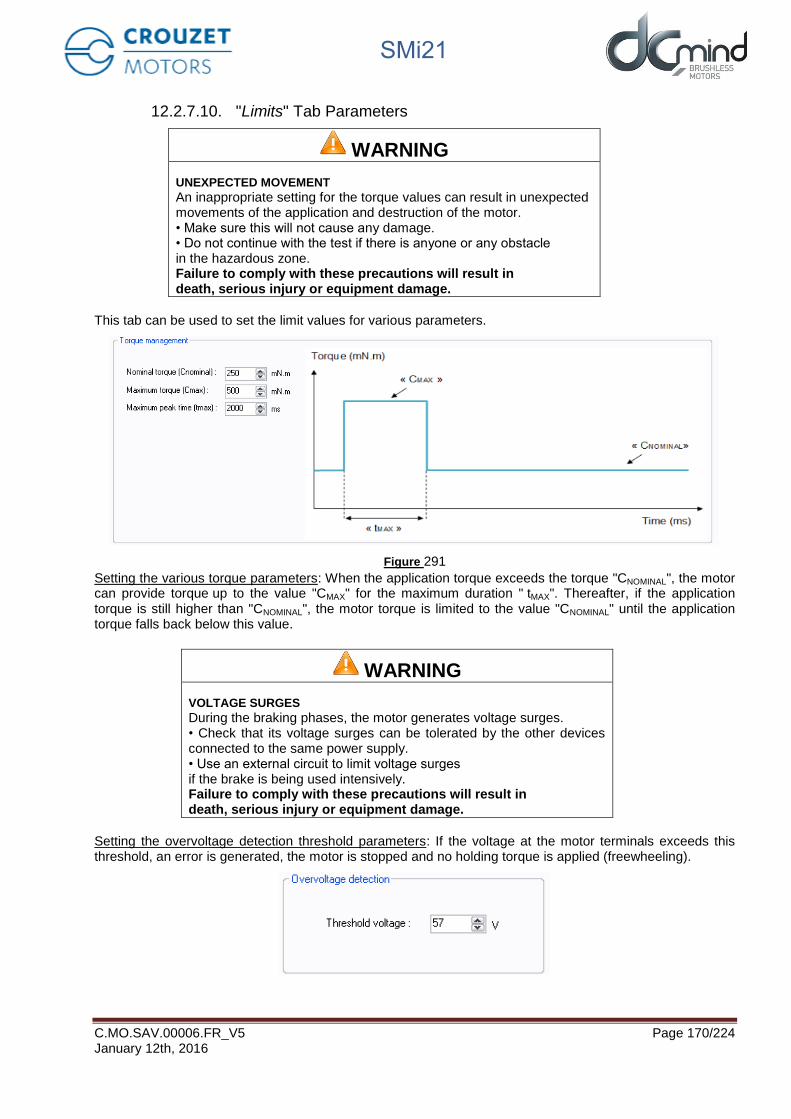
SMi21
C.MO.SAV.00006.FR_V5 Page 170/224 January 12th, 2016
12.2.7.10. "Limits" Tab Parameters
WARNING
UNEXPECTED MOVEMENT
An inappropriate setting for the torque values can result in unexpected movements of the application and destruction of the motor. • Make sure this will not cause any damage.• Do not continue with the test if there is anyone or any obstaclein the hazardous zone. Failure to comply with these precautions will result in death, serious injury or equipment damage.
This tab can be used to set the limit values for various parameters.
Figure 291
Setting the various torque parameters: When the application torque exceeds the torque "CNOMINAL", the motor can provide torque up to the value "CMAX" for the maximum duration " tMAX". Thereafter, if the application torque is still higher than "CNOMINAL", the motor torque is limited to the value "CNOMINAL" until the application torque falls back below this value.
WARNING
VOLTAGE SURGES
During the braking phases, the motor generates voltage surges. • Check that its voltage surges can be tolerated by the other devicesconnected to the same power supply. • Use an external circuit to limit voltage surgesif the brake is being used intensively. Failure to comply with these precautions will result in death, serious injury or equipment damage.
Setting the overvoltage detection threshold parameters: If the voltage at the motor terminals exceeds this threshold, an error is generated, the motor is stopped and no holding torque is applied (freewheeling).

SMi21
C.MO.SAV.00006.FR_V5 Page 171/224 January 12th, 2016
12.2.7.11. "Errors" Tab Parameters
Setting the parameters for the action to be taken when an over-torque error is encountered: real torque higher than the nominal torque "CNOMINAL" for a time longer than "tMAX".
Figure 292
For all errors affecting motor safety, the action to be taken cannot be configured: in the event of an error, the motor is stopped and no holding torque is applied (freewheeling).
Figure 293
Procedure for restarting the motor following detection of an error:
- Eliminate the cause of the fault. - Switch to stop mode: disable digital inputs 1 to 5. - Switch back to run mode: enable one of digital inputs 1 to 5.

SMi21
C.MO.SAV.00006.FR_V5 Page 172/224 January 12th, 2016
12.2.8. Description of the P200 Various Tabs
For the description of tabs, expert program P201 is used as an example (for detailed information about each position expert program, see the "Expert Program P201" and "Expert Program P202" sections in this document).
12.2.8.1. Home Page
This page is common to all the expert and application programs, whether in speed, position or torque mode. It can be used to choose between the various types of application and expert programs.
In our example, we have chosen the "Position P200" category in the "Expert Programs" group, so the icons for the various P200 expert programs appear in the bottom right-hand corner of the window, and you then need to click on the one corresponding to the "P201" expert program:
Figure 294
Expert program category selection: P200 Expert program selection: P201
Concise description of the P201 expert program

SMi21
C.MO.SAV.00006.FR_V5 Page 173/224 January 12th, 2016
12.2.8.2. "Description" Tab
This is an information tab containing a concise description of the various position profiles that are created using this expert mode:
Figure 295
Summary description of the profiles that can be created using this expert mode: position follows in live the position settings, choice between 2 speed profiles…
Option to name the project
I/O

SMi21
C.MO.SAV.00006.FR_V5 Page 174/224 January 12th, 2016
12.2.8.3. “Homing” Tab
This tab is used to select and configure the type of homing to be performed: offset(s), speed, homing torque, maximum duration of the homing phase, motor direction of rotation to search for the 1st stop.
Figure 296
12.2.8.4. “Inputs” Tab
This tab is used to configure the various inputs in this expert mode (speed profile : max speed, acceleration, deceleration ; application stroke…).
Figure 297
Summary description of the selected homing phase
Selection of the type of homing to be performed: 0, 1 or 2 mechanical
Parameters associated with the selected homing type.

SMi21
C.MO.SAV.00006.FR_V5 Page 175/224 January 12th, 2016
12.2.8.5. “Outputs” Tab
This tab is used to select and configure the various outputs in this expert mode (position type 5 to type 9):
Figure 298
Output 5 type parameter settings
Output 6 type parameter settings
Output 7 type parameter settings
Output 9 type parameter settings
Output 8 type parameter settings

SMi21
C.MO.SAV.00006.FR_V5 Page 176/224 January 12th, 2016
12.2.8.6. "Tuning" Tab
This tab is used to represent some parameters (speed, position, torque, etc.) in graphic form and modify the position control loop coefficients. It is common to all the position expert programs.
Figure 299
12.2.8.7. "Limits" Tab
This tab is used to configure the various motor operating limits: nominal and maximum torque (torque peak authorization), the power supply overvoltage threshold and the required accuracy for the positioning.
Figure 300
Setting the parameters associated with torque control.
Summary description of torque control.
Overvoltage threshold settings: if this value is exceeded, an error will be generated.
Setting of target’s tolerance for positioning
This tab is used to view the selected parameters in graphic form.
This zone is used to: - Select the parameters to be
viewed in graphic form - Set the position correction
factors - Set the display time - Export the data (.csv)

SMi21
C.MO.SAV.00006.FR_V5 Page 177/224 January 12th, 2016
12.2.8.8. "Errors" Tab
This tab provides information about the type of error encountered (based on the error code) and the action to be taken by the motor following this error.
Motor actions can be set when Over torque error or Position target error are detected (*not available, optional only).
Figure 301
Setting the action to be taken when an over torque error is encountered (*optional).
If an error is detected that could jeopardize motor safety, the motor is automatically turned off and left freewheeling.
Procedure for restarting the motor following detection of an error:
- Eliminate the cause of the fault. - Switch to stop mode and then back to run mode. -
Motor action selection when a target error is detected (*optional).

SMi21
C.MO.SAV.00006.FR_V5 Page 178/224 January 12th, 2016
12.2.9. Expert Program P201
12.2.9.1. Description
P201 expert program allows to:
- Perform a homing phase to initialize the system with detection of the stroke ends (mechanical stop or switch limit).
- Perform positioning in using two 0/10V analog inputs: One for coarse tuning and second for thin tuning. The total stroke (which has to be set per the user in this program) can be cut up to 65536 positions. The targeted position follows in live the 2 inputs.
- Select a speed profile (choice between 2 profiles) to go from a position to another position. A speed profile contains acceleration, deceleration and maximum allowed speed values.
12.2.9.2. "Homing" Tab Parameters
Set the polarity of the switch wired on digital input "In3":
Figure 302
Set the difference in position (in pulses) between the mechanical stops and the application total stroke limits: stop 1 (END1) represents the stroke start, stop 2 (END2) represents the stroke end.
Note: Where there is only one mechanical stop, the "Offset 2" parameter is not available.
Figure 303
Set the search speed for stops during the homing phase.
Figure 304
Set the homing torque that allows the mechanical stop to be found by detection of over-torque.

SMi21
C.MO.SAV.00006.FR_V5 Page 179/224 January 12th, 2016
Figure 305
Set the maximum permitted time for the homing phase. If this value is exceeded, an error will be generated. Time limited to 300 s.
Figure 306
Set the direction of rotation for the first stop search.
N.B.: By default, the motor runs forward (CW).
Figure 307

SMi21
C.MO.SAV.00006.FR_V5 Page 180/224 January 12th, 2016
12.2.9.3. "Inputs" Tab Parameters
Combinations of digital inputs 1 and 2: Used to choose the motion to be performed from the 4 actions indicated below.
Figure 308
Information concerning the polarity of the switch wired on digital input 3. This polarity is selected in the "Homing" tab (see above).
Figure 309
Digital input 4 - IN4 : Used to select one of the two speed profile.
To go from a position to a new position, motor follows a trapezoidal trajectory. This trajectory uses the
maximum speed, acceleration and deceleration which are set in the « Digital speed profile selection » zone.
Figure 310
NB : If the user needs to change its velocity profile during a positioning phase, it is strongly recommended to
use the same deceleration slope for both velocity profiles to ovoid overruns targets.

SMi21
C.MO.SAV.00006.FR_V5 Page 181/224 January 12th, 2016
Input IN5 and IN6 setpoints: To do the position setting using the two 0-10V analog inputs.
Parameter « total stroke lenght » is the number of encoder pulses corresponding to the stroke when IN5 and IN6 are at 10V.
Parameter “resolution coefficient” allows to cut the « total stroke length » in 2,048 or 4,096 or 8,192 or 16,384 or 32,768 or 65,536 positions.
The distribution of the « Total stroke length » on the two analog setpoint inputs is carried out according to the rules below.
- On IN5 : [0 − 10𝑉] ≡ [0 ; 𝑆𝑡𝑟𝑜𝑘𝑒𝑡𝑜𝑡𝑎𝑙_𝑎𝑝𝑝𝑙𝑖𝑐𝑎𝑡𝑖𝑜𝑛 ×𝐶𝑜𝑒𝑓𝑓𝑖𝑐𝑖𝑒𝑛𝑡_𝑟𝑒𝑠𝑜𝑙𝑢𝑡𝑖𝑜𝑛 −1
𝐶𝑜𝑒𝑓𝑓𝑖𝑐𝑖𝑒𝑛𝑡_𝑟𝑒𝑠𝑜𝑙𝑢𝑡𝑖𝑜𝑛] coded on 1024 points (coarse
setting)
- On IN6 : [0 − 10𝑉] ≡ [0 ; 𝐶𝑜𝑢𝑟𝑠𝑒𝑡𝑜𝑡𝑎𝑙𝑒_𝑎𝑝𝑝𝑙𝑖𝑐𝑎𝑡𝑖𝑜𝑛 ×1
𝐶𝑜𝑒𝑓𝑓𝑖𝑐𝑖𝑒𝑛𝑡_𝑟é𝑠𝑜𝑙𝑢𝑡𝑖𝑜𝑛] coded on 1024 points (thin setting)
Figure 311
Figure 312
The motor position setpoint is the addition of position setpoint of IN5 and of position setpoint of IN6.
In above example :
- On IN5 : [0 − 10𝑉] ≡ [0 ; 40960 ×16−1
16] = [0 ; 38400] coded on 1,024 points (coarse setting)
- On IN6 : [0 − 10𝑉] ≡ [0 ; 40960 ×1
16] = [0 ; 2560] coded on 1,024 points (thin setting)
Note : The sign (-) at the 10V setpoint depends from the direction of rotation during the homing sequence.

SMi21
C.MO.SAV.00006.FR_V5 Page 182/224 January 12th, 2016
12.2.9.4. Type 5 "Outputs" Tab Parameters
State of digital output 1 "Target Reached Flag": Used to find out whether the position setpoint has been reached.
Figure 313
State of digital output 2 "Homing Sequence Information": Used to find out how the homing phase is progressing: completed, in progress or not performed.
Figure 314
State of digital output 3 "Motor running": Used to find out whether the motor is stopped or running.
Figure 315
State of digital output 4 "Error": Used to find out whether an error has been detected.
Figure 316

SMi21
C.MO.SAV.00006.FR_V5 Page 183/224 January 12th, 2016
12.2.9.5. Type 6 "Outputs" Tab Parameters
State of digital output 1 "Target Reached Flag": Used to find out whether the position setpoint has been reached.
Figure 317
State of digital output 2 "Homing Sequence Information": Used to find out how the homing phase is progressing: completed, in progress or not performed.
Figure 318
State of digital output 3 "Motor running": Used to find out whether the motor is stopped or running.
Figure 319
State of digital output 4 "Error": Used to find out whether an error has been detected.
Figure 320

SMi21
C.MO.SAV.00006.FR_V5 Page 184/224 January 12th, 2016
12.2.9.6. Type 7 "Outputs" Tab Parameters
State of digital output 1 "Target Reached Flag": Used to find out whether the position setpoint has been reached.
Figure 321
Setting the parameters of PWM output 2 "Real torque (centered on 50%)": The parameters can be set for the signal frequency of this output and the torque value corresponding to a cyclical ratio of 100% (scaling).
If cyclical ratio = 0% → Braking torque supplied = "S2 torque". If cyclical ratio = 50% → Torque supplied = 0 mNm. If cyclical ratio = 100% → Motor torque supplied = "S2 torque".
Figure 322
Combinations of digital outputs 3 & 4 "Motor status": Used to find out the motor status.
Figure 323

SMi21
C.MO.SAV.00006.FR_V5 Page 185/224 January 12th, 2016
12.2.9.7. Type 8 "Outputs" Tab Parameters
State of digital output 1 "Target Reached Flag": Used to find out whether the position setpoint has been reached.
Figure 324
Setting the parameters of PWM output 2 "Real torque (centered on 50%)": The parameters can be set for the signal frequency of this output and the torque value corresponding to a cyclical ratio of 100% (scaling).
If cyclical ratio = 0% → Braking torque supplied = "S2 torque". If cyclical ratio = 50% → Torque supplied = 0 mNm. If cyclical ratio = 100% → Motor torque supplied = "S2 torque".
Figure 325
Combinations of digital outputs 3 & 4 "Motor status": Used to find out the motor status.
Figure 326

SMi21
C.MO.SAV.00006.FR_V5 Page 186/224 January 12th, 2016
12.2.9.8. Type 9 "Outputs" Tab Parameters
Setting the parameters of Pulse output 1 "Real speed": A Hall pulse with configurable width (100 to 800 µs) is generated each time one of the 3 motor Hall sensors changes state.
80140_SMi21 and 80180_SMi21 motors have 12 Hall pulses per revolution (2 pairs of poles). The 80280_SMi21 motor has 24 Hall pulses per revolution (4 pairs of poles).
Figure 327
State of digital output 2 "Real direction": Used to find out the motor direction of rotation.
Figure 328
Combinations of digital outputs 3 & 4 "Motor status": Used to find out the motor status.
Figure 329

SMi21
C.MO.SAV.00006.FR_V5 Page 187/224 January 12th, 2016
12.2.9.9. "Tuning" Tab Parameters
Selection of the various parameters to be represented in graphic form: either 1, 2, 3 or 4 parameters. The system position response (measurement vs setpoint) can therefore be compared while displaying changes in the current and the speed.
Figure 330
Set the PID controller factors in the position control loop (this function is reserved for advanced users). The values given in the example below ensure correct product operation in the majority of cases.
Figure 331
It is possible to set the recording time you wish to view, from 1 to 300 seconds. The sampling interval is 10 ms. During data acquisition, the other HMI functions are not available.
Figure 332
"Curve Drawing" button: used to start data acquisition. Curves are only displayed once acquisition is complete.
"Export Data" button: used to retrieve data corresponding to the selected parameters in a text file (.txt). To make this file compatible with the Excel spreadsheet, change its extension to .csv.
Figure 333

SMi21
C.MO.SAV.00006.FR_V5 Page 188/224 January 12th, 2016
Example:
- Application total stroke length = 2000000 pulses - Speed profile: speed = 1000 rpm / acceleration = 400 rpm/sec / deceleration = 100 rpm/sec - The following results were obtained :
NB: The display scales can be changed with the mouse wheel. Other functions are available by right-clicking the mouse.
Figure 334
Position setpoint
Real speed
Real position

SMi21
C.MO.SAV.00006.FR_V5 Page 189/224 January 12th, 2016
12.2.9.10. "Limits" Tab Parameters
WARNING
UNEXPECTED MOVEMENT
An inappropriate setting for the torque values can result in unexpected movements of the application and destruction of the motor. • Make sure this will not cause any damage.• Do not continue with the test if there is anyone or any obstaclein the hazardous zone. Failure to comply with these precautions will result in death, serious injury or equipment damage.
This tab can be used to set the limit values for various parameters.
Figure 335
Setting the various torque parameters: When the application torque exceeds the torque "CNOMINAL", the motor can provide torque up to the value "CMAX" for the maximum duration " tMAX". Thereafter, if the application torque is still higher than "CNOMINAL", the motor torque is limited to the value "CNOMINAL" until the application torque falls back below this value.
WARNING
VOLTAGE SURGES
During the braking phases, the motor generates voltage surges. • Check that its voltage surges can be tolerated by the other devicesconnected to the same power supply. • Use an external circuit to limit voltage surgesif the brake is being used intensively. Failure to comply with these precautions will result in death, serious injury or equipment damage.
Setting the overvoltage detection threshold parameters: If the voltage at the motor terminals exceeds this threshold, an error is generated, the motor is stopped and no holding torque is applied (freewheeling).

SMi21
C.MO.SAV.00006.FR_V5 Page 190/224 January 12th, 2016
Figure 336
Setting of the « Acceptable position accuracy » for the position to reach : This value gives the acceptable tolerance to consider that the target position is reached. The output « target reached » will become active when motor position will be at the position [targeted position +/- the « Acceptable position accuracy »].
Figure 337

SMi21
C.MO.SAV.00006.FR_V5 Page 191/224 January 12th, 2016
12.2.9.11. "Errors" Tab Parameters
Setting the parameters for the action to be taken when an over-torque error is encountered: real torque higher than the nominal torque "CNOMINAL" for a time longer than "tMAX" (in option).
Figure 338
For all errors affecting motor safety, the action to be taken cannot be configured: in the event of an error, the motor is stopped and no holding torque is applied (freewheeling).
Figure 339
Setting of the action to perform when a target error is detected : (not available, optional only)
When motor is not able to achieve in the required time limit its position target +/- the “Acceptable position accuracy », the “Position target error” is activated and the selected action will occur.
Figure 340
Procedure for restarting the motor following detection of an error:
- Eliminate the cause of the fault. - Switch to stop mode: Inhibit inputs 1 and 2 (IN1 = IN2 = 0) to be in the « stop and erase error » mode. - Go back to a running mode in activating input 1 or 2 or the both.

SMi21
C.MO.SAV.00006.FR_V5 Page 192/224 January 12th, 2016
12.2.10. Expert Program P202
12.2.10.1. Description
P202 expert program allows to:
- Perform a homing phase to initialize the system with detection of the stroke ends (mechanical stop or switch limit).
- Define a position setpoint in using two 0/10V analog inputs: One for coarse tuning and second for thin tuning. The total stroke (which has to be set per the user in this program) can be cut up to 65536 positions.
- Memorize the new position setpoint
- Go to the new position target
- Select a speed profile (choice between 2 profiles) to go from a position to another position. A speed profile contains acceleration, deceleration and maximum allowed speed values.
12.2.10.2. "Homing" Tab Parameters
Set the polarity of the switch wired on digital input "In3":
Figure 341
Set the difference in position (in pulses) between the mechanical stops and the application total stroke limits: stop 1 (END1) represents the stroke start, stop 2 (END2) represents the stroke end.
Note: Where there is only one mechanical stop, the "Offset 2" parameter is not available.
Figure 342
Set the search speed for stops during the homing phase.
Figure 343
Set the homing torque that allows the mechanical stop to be found by detection of overtorque.

SMi21
C.MO.SAV.00006.FR_V5 Page 193/224 January 12th, 2016
Figure 344
Set the maximum permitted time for the homing phase. If this value is exceeded, an error will be generated. Time limited to 300 s.
Figure 345
Set the direction of rotation for the first stop search.
N.B.: By default, the motor runs forward (CW).
Figure 346

SMi21
C.MO.SAV.00006.FR_V5 Page 194/224 January 12th, 2016
12.2.10.3. "Inputs" Tab Parameters
Combinations of digital inputs 1 and 2: Used to choose the motion to be performed from the 4 actions indicated below.
Figure 347
Information concerning the polarity of the switch wired on digital input 3. This polarity is selected in the "Homing" tab (see above).
Figure 348
Digital input 4 - IN4 : Used to select one of the two speed profile.
To go from a position to a new position, motor follows a trapezoidal trajectory. This trajectory uses the
maximum speed, acceleration and deceleration which are set in the « Digital speed profile selection » zone.
Figure 349
Note : If the user needs to change its velocity profile during a positioning phase, it is strongly recommended
to use the same deceleration slope for both velocity profiles to ovoid overruns targets.

SMi21
C.MO.SAV.00006.FR_V5 Page 195/224 January 12th, 2016
Input IN5 and IN6 setpoints: To do the position setting using the two 0-10V analog inputs.
Parameter « total stroke lenght » is the number of encoder pulses corresponding to the stroke when IN5 and IN6 are at 10V.
Parameter “resolution coefficient” allows to cut the « total stroke length » in 2,048 or 4,096 or 8,192 or 16,384 or 32,768 or 65,536 positions.
The distribution of the « Total stroke length » on the two analog setpoint inputs is carried out according to the rules below.
- On IN5 : [0 − 10𝑉] ≡ [0 ; 𝑆𝑡𝑟𝑜𝑘𝑒𝑒𝑡𝑜𝑡𝑎𝑙𝑒_𝑎𝑝𝑝𝑙𝑖𝑐𝑎𝑡𝑖𝑜𝑛 ×𝐶𝑜𝑒𝑓𝑓𝑖𝑐𝑖𝑒𝑛𝑡_𝑟𝑒𝑠𝑜𝑙𝑢𝑡𝑖𝑜𝑛 −1
𝐶𝑜𝑒𝑓𝑓𝑖𝑐𝑖𝑒𝑛𝑡_𝑟𝑒𝑠𝑜𝑙𝑢𝑡𝑖𝑜𝑛] coded on 1024 points (coarse
setting)
- On IN6 : [0 − 10𝑉] ≡ [0 ; 𝑆𝑡𝑟𝑜𝑘𝑒𝑡𝑜𝑡𝑎𝑙𝑒_𝑎𝑝𝑝𝑙𝑖𝑐𝑎𝑡𝑖𝑜𝑛 ×1
𝐶𝑜𝑒𝑓𝑓𝑖𝑐𝑖𝑒𝑛𝑡_𝑟é𝑠𝑜𝑙𝑢𝑡𝑖𝑜𝑛] coded on 1024 points (thin setting)
Figure 350
Figure 351
The motor position setpoint is the addition of position setpoint of IN5 and of position setpoint of IN6.
In above example :
- On IN5 : [0 − 10𝑉] ≡ [0 ; 40960 ×16−1
16] = [0 ; 38400] coded on 1,024 points (coarse setting)
- On IN6 : [0 − 10𝑉] ≡ [0 ; 40960 ×1
16] = [0 ; 2560] coded on 1,024 points (thin setting)
Note : The sign (-) at the 10V setpoint depends from the direction of rotation during the homing sequence.

SMi21
C.MO.SAV.00006.FR_V5 Page 196/224 January 12th, 2016
12.2.10.4. Type 5 "Outputs" Tab Parameters
State of digital output 1 "Target Reached Flag": Used to find out whether the position setpoint has been reached.
Figure 352
State of digital output 2 "Homing Sequence Information": Used to find out how the homing phase is progressing: completed, in progress or not performed.
Figure 353
State of digital output 3 "Motor running": Used to find out whether the motor is stopped or running.
Figure 354
State of digital output 4 "Error": Used to find out whether an error has been detected.
Figure 355

SMi21
C.MO.SAV.00006.FR_V5 Page 197/224 January 12th, 2016
12.2.10.5. Type 6 "Outputs" Tab Parameters
State of digital output 1 "Target Reached Flag": Used to find out whether the position setpoint has been reached.
Figure 356
State of digital output 2 "Homing Sequence Information": Used to find out how the homing phase is progressing: completed, in progress or not performed.
Figure 357
State of digital output 3 "Motor running": Used to find out whether the motor is stopped or running.
Figure 358
State of digital output 4 "Error": Used to find out whether an error has been detected.
Figure 359

SMi21
C.MO.SAV.00006.FR_V5 Page 198/224 January 12th, 2016
12.2.10.6. Type 7 "Outputs" Tab Parameters
State of digital output 1 "Target Reached Flag": Used to find out whether the position setpoint has been reached.
Figure 360
Setting the parameters of PWM output 2 "Real torque (centered on 50%)": The parameters can be set for the signal frequency of this output and the torque value corresponding to a cyclical ratio of 100% (scaling).
If cyclical ratio = 0% → Braking torque supplied = "S2 torque". If cyclical ratio = 50% → Torque supplied = 0 mNm. If cyclical ratio = 100% → Motor torque supplied = "S2 torque".
Figure 361
Combinations of digital outputs 3 & 4 "Motor status": Used to find out the motor status.
Figure 362

SMi21
C.MO.SAV.00006.FR_V5 Page 199/224 January 12th, 2016
12.2.10.7. Type 8 "Outputs" Tab Parameters
State of digital output 1 "Target Reached Flag": Used to find out whether the position setpoint has been reached.
Figure 363
Setting the parameters of PWM output 2 "Real torque (centered on 50%)": The parameters can be set for the signal frequency of this output and the torque value corresponding to a cyclical ratio of 100% (scaling).
If cyclical ratio = 0% → Braking torque supplied = "S2 torque". If cyclical ratio = 50% → Torque supplied = 0 mNm. If cyclical ratio = 100% → Motor torque supplied = "S2 torque".
Figure 364
Combinations of digital outputs 3 & 4 "Motor status": Used to find out the motor status.
Figure 365

SMi21
C.MO.SAV.00006.FR_V5 Page 200/224 January 12th, 2016
12.2.10.8. Type 9 "Outputs" Tab Parameters
Setting the parameters of Pulse output 1 "Real speed": A Hall pulse with configurable width (100 to 800 µs) is generated each time one of the 3 motor Hall sensors changes state.
80140_SMi21 and 80180_SMi21 motors have 12 Hall pulses per revolution (2 pairs of poles). The 80280_SMi21 motor has 24 Hall pulses per revolution (4 pairs of poles).
Figure 366
State of digital output 2 "Real direction": Used to find out the motor direction of rotation.
Figure 367
Combinations of digital outputs 3 & 4 "Motor status": Used to find out the motor status.
Figure 368

SMi21
C.MO.SAV.00006.FR_V5 Page 201/224 January 12th, 2016
12.2.10.9. "Tuning" Tab Parameters
Selection of the various parameters to be represented in graphic form: either 1, 2, 3 or 4 parameters. The system position response (measurement vs setpoint) can therefore be compared while displaying changes in the current and the speed.
Figure 369
Set the PID controller factors in the position control loop (this function is reserved for advanced users). The values given in the example below ensure correct product operation in the majority of cases.
Figure 370
It is possible to set the recording time you wish to view, from 1 to 300 seconds. The sampling interval is 10 ms. During data acquisition, the other HMI functions are not available.
Figure 371
"Curve Drawing" button: used to start data acquisition. Curves are only displayed once acquisition is complete.
"Export Data" button: used to retrieve data corresponding to the selected parameters in a text file (.txt). To make this file compatible with the Excel spreadsheet, change its extension to .csv.
Figure 372

SMi21
C.MO.SAV.00006.FR_V5 Page 202/224 January 12th, 2016
Example:
- Application total stroke length = 2000000 pulses - Speed profile: speed = 1000 rpm / acceleration = 400 rpm/sec / deceleration = 100 rpm/sec - The following results were obtained :
Note: The display scales can be changed with the mouse wheel. Other functions are available by right-clicking the mouse.
Figure 373
Position setpoint
Real speed
Real position

SMi21
C.MO.SAV.00006.FR_V5 Page 203/224 January 12th, 2016
12.2.10.10. "Limits" Tab Parameters
WARNING
UNEXPECTED MOVEMENT
An inappropriate setting for the torque values can result in unexpected movements of the application and destruction of the motor. • Make sure this will not cause any damage.• Do not continue with the test if there is anyone or any obstaclein the hazardous zone. Failure to comply with these precautions will result in death, serious injury or equipment damage.
This tab can be used to set the limit values for various parameters.
Figure 374
Setting the various torque parameters: When the application torque exceeds the torque "CNOMINAL", the motor can provide torque up to the value "CMAX" for the maximum duration " tMAX". Thereafter, if the application torque is still higher than "CNOMINAL", the motor torque is limited to the value "CNOMINAL" until the application torque falls back below this value.
WARNING
VOLTAGE SURGES
During the braking phases, the motor generates voltage surges. • Check that its voltage surges can be tolerated by the other devicesconnected to the same power supply. • Use an external circuit to limit voltage surgesif the brake is being used intensively. Failure to comply with these precautions will result in death, serious injury or equipment damage.
Setting the overvoltage detection threshold parameters: If the voltage at the motor terminals exceeds this threshold, an error is generated, the motor is stopped and no holding torque is applied (freewheeling).

SMi21
C.MO.SAV.00006.FR_V5 Page 204/224 January 12th, 2016
Figure 375
Setting of the « Acceptable position accuracy » for the position to reach : This value gives the acceptable tolerance to consider that the target position is reached. The output « target reached » will become active when motor position will be at the position [targeted position +/- the « Acceptable position accuracy »].
Figure 376

SMi21
C.MO.SAV.00006.FR_V5 Page 205/224 January 12th, 2016
12.2.10.11. "Errors" Tab Parameters
Setting the parameters for the action to be taken when an over-torque error is encountered: real torque higher than the nominal torque "CNOMINAL" for a time longer than "tMAX" (in option).
Figure 377
For all errors affecting motor safety, the action to be taken cannot be configured: in the event of an error, the motor is stopped and no holding torque is applied (freewheeling).
Figure 378
Setting of the action to perform when a target error is detected : (not available, optional only)
When motor is not able to achieve in the required time limit its position target +/- the “Acceptable position accuracy », the “Position target error” is activated and the selected action will occur.
Figure 379
Procedure for restarting the motor following detection of an error:
- Eliminate the cause of the fault. - Switch to stop mode: Inhibit inputs 1 and 2 (IN1 = IN2 = 0) to be in the « stop and erase error » mode. - Go back to a running mode in activating input 1 or 2 or the both.

SMi21
C.MO.SAV.00006.FR_V5 Page 206/224 January 12th, 2016
12.3. Torque Programs
12.3.1. Types of Inputs in C100 Programs
The table below defines the function associated with each of the inputs in the 2 C100 programs (the color associated with the input number corresponds to that of the I/O bundle):
Programs
Inputs C101 C102
In1 ON/OFF 000 : "In6" torque setpoint 001 : Priority torque 1 010 : Priority torque 2 100 : Priority torque 3
In2 Direction
In3 Not used
In4 Fast stop 00 : Fast stop 10 : CCW 01 : CW 11 : Stop, disable error
In5 Torque ramp
In6 Torque Torque
(if In1 = In2 = In3 = 0)
Key: Digital type input
Analog or PWM type input
Forthcoming programs
12.3.2. Types of Outputs in C100 Programs
For all expert torque programs, we have 2 configurable output configurations (the color associated with the output number corresponds to that of the I/O bundle):
Out1 Out2 Out3 Out4
Type 2 Real speed Real torque Motor running Error
PWM PWM Digital Digital
Type 10
Real speed (centered on
50%)
Real torque (centered on
50%)
00 : error detected 01 : motor running 10 : motor stopped, torque position reached and held 11 : motor stopped, no torque applied
PWM PWM Digital combinations
Key: Digital type output
PWM/Pulse/Frequency type output

SMi21
C.MO.SAV.00006.FR_V5 Page 207/224 January 12th, 2016
12.3.3. Description of the Various Tabs
For the description of tabs, expert program C101 is used as an example (for detailed information about each torque expert program, see the "Expert Program C101" section in this document).
12.3.3.1. Home Page
This page is common to all the expert and application programs, whether in speed, position or torque mode. It can be used to choose between the various types of application and expert programs.
In our example, we have chosen the "Torque C100" category in the "Expert Programs" group, so the icons for the various C100 expert programs appear in the bottom right-hand corner of the window, and you then need to click on the one corresponding to the "C101" expert program:
Figure 380
Expert program category selection: C100 Expert program selection: C101
Concise description of the C101 expert program
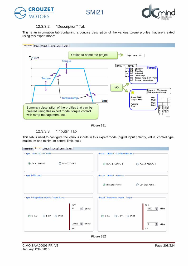
SMi21
C.MO.SAV.00006.FR_V5 Page 208/224 January 12th, 2016
12.3.3.2. "Description" Tab
This is an information tab containing a concise description of the various torque profiles that are created using this expert mode:
Figure 381
12.3.3.3. "Inputs" Tab
This tab is used to configure the various inputs in this expert mode (digital input polarity, value, control type, maximum and minimum control limit, etc.):
Figure 382
Summary description of the profiles that can be created using this expert mode: torque control with ramp management, etc.
Option to name the project
I/O

SMi21
C.MO.SAV.00006.FR_V5 Page 209/224 January 12th, 2016
12.3.3.4. "Outputs" Tab
This tab is used to select and configure the various outputs in this expert mode (torque type 2 and type 10):
12.3.3.5. "Tuning" Tab
This tab is used to represent some parameters (speed, torque, etc.) in graphic form and modify the torque control loop coefficients. It is common to all the torque expert programs.
Figure 384
Output 2 type parameter settings
Output 10 type parameter settings
Figure 383
This tab is used to view the selected parameters in graphic form.
This zone is used to: - Select the parameters to be
viewed in graphic form - Set the torque correction
factors - Set the display time - Export the data (.csv)

SMi21
C.MO.SAV.00006.FR_V5 Page 210/224 January 12th, 2016
12.3.3.6. "Limits" Tab
This tab can be used to set the power supply overvoltage threshold.
Figure 385
12.3.3.7. "Errors" Tab
This tab provides information about the type of error encountered (based on the error code) and the action to be taken by the motor following this error.
Figure 386
Overvoltage threshold settings: if this value is exceeded, an error will be generated.
If an error is detected that could jeopardize motor safety, the motor is automatically turned off and left freewheeling.
Procedure for restarting the motor following detection of an error:
- Eliminate the cause of the fault. - Switch to stop mode.

SMi21
C.MO.SAV.00006.FR_V5 Page 211/224 January 12th, 2016
12.3.4. Expert Program C101
12.3.4.1. Description
Expert program C101 is used to:
- Create torque profiles with analog or PWM control.
- Set the torque up and down ramps with analog or PWM control.
12.3.4.2. "Inputs" Tab Parameters
Digital input 1: Used to set the "On/Off" input polarity.
Figure 387
Digital input 2: Used to set the "Direction of Rotation" input polarity.
Figure 388
Digital input 3: Not used
Digital input 4: Used to set the "Fast stop" input polarity.
This input is used to stop the motor as quickly as possible, ignoring the setpoints applied to the other inputs.
Figure 389

SMi21
C.MO.SAV.00006.FR_V5 Page 212/224 January 12th, 2016
Setpoint input 5: Used to select the control type for the torque ramp setpoint and fix the maximum and minimum limits for this setpoint. An inverted scale can be used.
Figure 390
Setpoint input 6: Used to select the control type for the torque setpoint and fix the maximum and minimum limits for this setpoint. An inverted scale can be used.
Figure 391

SMi21
C.MO.SAV.00006.FR_V5 Page 213/224 January 12th, 2016
12.3.4.3. Type 2 "Outputs" Tab Parameters
Setting the parameters of PWM output 1 "Real Speed": The parameters can be set for the signal frequency of this output (must be identical to the one for PWM output 2).
If cyclical ratio = 0% → Real speed = 0 rpm. If cyclical ratio = 100% → Real speed = maximum speed setpoint defined in In6.
Figure 392
Setting the parameters of PWM output 2 "Real Torque": The parameters can be set for the signal frequency of this output (must be identical to the one for PWM output 1) and the torque value corresponding to a cyclical ratio of 100% (scaling).
If cyclical ratio = 0% → Torque supplied = 0 mNm. If cyclical ratio = 100% → Torque supplied = "S2 torque".
Figure 393
State of digital output 3 "Motor Running": Used to find out whether the motor is stopped or running.
Figure 394
State of digital output 4 "Error": Used to find out whether an error has been detected.
Figure 395

SMi21
C.MO.SAV.00006.FR_V5 Page 214/224 January 12th, 2016
12.3.4.4. Type 10 "Outputs" Tab Parameters
Setting the parameters of PWM output 1: "Real speed (centered on 50%)": The parameters can be set for the signal frequency of this output (must be identical to the one for PWM output 2).
If cyclical ratio = 0% → Motor running forward (CW) at maximum speed setpoint defined in In6. If cyclical ratio = 50% → Real speed = 0 rpm. If cyclical ratio = 100% → Motor running in reverse (CCW) at maximum speed setpoint defined in In6.
Figure 396
Setting the parameters of PWM output 2 "Real torque (centered on 50%)": The parameters can be set for the signal frequency of this output (must be identical to the one for PWM output 1) and the torque value corresponding to a cyclical ratio of 100% (scaling).
If cyclical ratio = 0% → Braking torque supplied = "S2 torque". If cyclical ratio = 50% → Torque supplied = 0 mNm. If cyclical ratio = 100% → Motor torque supplied = "S2 torque".
Figure 397
Combinations of digital outputs 3 & 4 "Motor status": Used to find out the motor status.
Figure 398

SMi21
C.MO.SAV.00006.FR_V5 Page 215/224 January 12th, 2016
12.3.4.5. "Tuning" Tab Parameters
Selection of the various parameters to be represented in graphic form: either 1, 2 or 3 parameters. The system torque response (measurement vs setpoint) can therefore be compared while displaying changes in the speed.
Figure 399
Set the PID controller factors in the torque control loop (this function is reserved for advanced users). The values given in the example below ensure correct product operation in the majority of cases.
Figure 400
It is possible to set the recording time you wish to view, from 1 to 300 seconds. The sampling interval is 10 ms. During data acquisition, the other HMI functions are not available.
Figure 401
"Curve Drawing" button: used to start data acquisition. Curves are only displayed once acquisition is complete.
"Export Data" button: used to retrieve data corresponding to the selected parameters in a text file (.txt). To make this file compatible with the Excel spreadsheet, change its extension to .csv.
Figure 402

SMi21
C.MO.SAV.00006.FR_V5 Page 216/224 January 12th, 2016
Example: With a torque setpoint on input 6 at 200 mN.m and a torque ramp setpoint on input 5 at 50 mN.m/s, this gives us the following graphic representation (recording time of 20 seconds):
Figure 403
Note: The display scales can be changed with the mouse wheel. Other functions are available by right-clicking the mouse.
Figure 404
Torque setpoint Real torque

SMi21
C.MO.SAV.00006.FR_V5 Page 217/224 January 12th, 2016
12.3.4.6. "Limits" Tab Parameters
WARNING
VOLTAGE SURGES
During the braking phases, the motor generates voltage surges. • Check that its voltage surges can be tolerated by the other devicesconnected to the same power supply. • Use an external circuit to limit voltage surgesif the brake is being used intensively. Failure to comply with these precautions will result in death, serious injury or equipment damage.
Setting the overvoltage detection threshold parameters: If the voltage at the motor terminals exceeds this threshold, an error is generated, the motor is stopped and no holding torque is applied (freewheeling).
Figure 405
12.3.4.7. "Errors" Tab Parameters
For all errors affecting motor safety, the action to be taken cannot be configured: in the event of an error, the motor is stopped and no holding torque is applied (freewheeling).
Figure 406
Procedure for restarting the motor following detection of an error:
- Eliminate the cause of the fault. - Switch to stop mode: disable digital input 1 "On/Off". - Switch back to run mode: enable digital input 1 "On/Off".

SMi21
C.MO.SAV.00006.FR_V5 Page 218/224 January 12th, 2016
13. SAVING PARAMETERS
In all the expert programs (speed, position and torque), the user can give a name to his project (4 alphanumerical characters maximum) using the "Project name" parameter in the program "Description" tab (expert program V101 will be used as an example):
Figure 407
The "Project name" parameter can be accessed by clicking the "Motor Information" tab in the main menu bar:
Figure 408
The project parameters can be saved in an .xml file by clicking on "Save As" in the "File" tab of the main menu.
Figure 409
They can also be reused by clicking on "Open" in the "File" tab of the main menu, then selecting the appropriate "MOT1.xml" file.
Updating the parameter "Project name"

SMi21
C.MO.SAV.00006.FR_V5 Page 219/224 January 12th, 2016
Figure 410
Figure 411
Select the parameter backup file

SMi21
C.MO.SAV.00006.FR_V5 Page 220/224 January 12th, 2016
When the parameter file is uploaded, the HMI automatically launches the associated expert or application program (in our example expert program V101):
Figure 412
Press the "Load Program" button to load the "MOT1.xml" file parameters in the motor.
Load saved parameters

SMi21
C.MO.SAV.00006.FR_V5 Page 221/224 January 12th, 2016
14. DIAGNOSTICS AND TROUBLESHOOTING
14.1. Mechanical Failures
Error Cause Remedy Significant temperature rise Overload
Holding brake not released Reduce the load Check control of the holding brake
Whistling or knocking Faulty bearings Contact the after-sales service Friction noise A rotary transmission device is catching Align the transmission device Radial vibration Transmission device incorrectly aligned
Transmission device unbalanced Twisted shaft Resonance in the fixing
Align the transmission device Balance the transmission device Contact the after-sales service Check the rigidity of the motor fixing
Axial vibration Transmission device incorrectly aligned Transmission device being knocked Resonance in the fixing
Align the transmission device Check the transmission device Check the rigidity of the motor fixing
14.2. Electrical Failures
Error Cause Remedy The motor does not start or starts with difficulty
Overload Fault in the connection wires
Reduce the load Check the connection wires Contact the after-sales service
Significant temperature rise in the stator
Overload Reduce the load
Temperature rise in the connection terminals
Power supply wires disconnected or loose
Tighten the screws

SMi21
C.MO.SAV.00006.FR_V5 Page 222/224 January 12th, 2016
15. SERVICE, MAINTENANCE AND DISPOSAL
15.1. Addresses of After-Sales Service Outlets
Please contact your distributor. The list of distributors is accessible on the CROUZET Automatismes website www.crouzet.com
15.2. Storage
The motors must only be transported and stored in dry, dust-free environments that are resistant to vibration. The ambient conditions are stated in the product technical data sheet and must be adhered to. The storage period is essentially dictated by the stability of the lubricants and should be less than 36 months. To keep the motor in working order, it is advisable to start up the drive solution occasionally.
15.3. Maintenance
Only the manufacturer is authorized to undertake repairs. Any personal intervention voids any guarantee and precludes manufacturer liability. Repairs cannot be performed with the motor mounted.
Prior to any intervention on the drive system, please refer to the Installation and Commissioning sections to find out what steps to take.
We recommend that the following operations are done at regular intervals. Connections and fixing => Check the connection cables and connections regularly for signs of damage. Replace any damaged cables immediately. => Check that all the transmission devices are fully tightened. => Retighten all the mechanical and electrical bolted connections to the appropriate tightening torque.
WARNING
UNEXPECTED MOVEMENT
Exceeding the permissible ambient conditions can allow foreign bodies from the surrounding area to get in and lead to unexpected motor movements or damage to equipment. • Check the ambient conditions.• It is vital to avoid fluid stagnation in the shaft bushing.Failure to comply with these precautions can result in death, serious injury or damage to equipment.
Cleaning Clean the motor regularly to remove any dust and dirt. If heat cannot dissipate adequately into the ambient air, this can cause abnormally high temperatures. The motors are not designed to be cleaned with high-pressure washers. Jet washing can cause water to get inside the motor. When using cleaning products or solvents, take care not to damage the motor power supply leads and any options (brake), ball bearings and the motor coating.
Check/run in the holding brake Occasional braking with a shifted load helps conserve the holding brake's holding torque. If the holding brake produces no mechanical work over a prolonged period (braking with a shifted load), some parts of the holding brake can corrode or other deposits can accumulate and thus reduce the holding torque.
The holding brake has been run in on leaving the factory. If the holding brake produces no mechanical work over a prolonged period, some parts of the holding brake can corrode. If the holding brake should not demonstrate the holding torque specified in the technical specifications, it would need to be run in again:

SMi21
C.MO.SAV.00006.FR_V5 Page 223/224 January 12th, 2016
=> The motor is not mounted. The holding brake is engaged. => Measure the brake holding torque using a torque wrench. => Compare the value with the holding torque indicated on the technical data sheet. => If the holding torque is markedly different from the stated values, turn the motor shaft by hand 25 turns in both directions. => Repeat the operation. If the holding torque has not been restored after 3 repeat operations, please contact your vendor.
15.4. Replacing the Motor
=> Disconnect all the supply voltages. Make sure that no other voltage is applied (safety instructions). => Mark all connections and demount the product. => Replace it with a motor with the same part number. => Install the new product as described in section 4 "Installation". => Commission the product as described in section 5 "Commissioning".
15.5. Dispatch, Storage, Disposal
Comply with the ambient conditions described in the "TECHNICAL SPECIFICATIONS" section.
Dispatch Protect the product against shocks during transport. Use the original packaging for this purpose.
Storage Only store the product in the stated permissible ambient conditions in terms of temperature and air humidity. Protect the product against dust and dirt.
Disposal The product is made up of various materials that can be reused or are suitable for separation and recycling. Dispose of the product in accordance with local regulations.

SMi21
C.MO.SAV.00006.FR_V5 Page 224/224 January 12th, 2016
15.6. Terminology and Abbreviations
Encoder Mounted on the motor, the angular position sensor provides frequency pulses proportional to the motor speed.
Degree of protection The degree of protection is a standard definition used for electrical equipment that aims to describe the protection against penetration of solids and liquids inside the motor casing (for example IP54M). The M indicates that the tests are conducted with the motor running. This value cannot take account of the seal around the output shaft, for which the installer must take responsibility.
Axial forces Longitudinal traction or compression forces affecting the shaft.
Radial forces Radial forces affecting the shaft.
Direction of rotation Positive or negative direction of rotation of the motor shaft. The positive direction of rotation is clockwise rotation of the motor shaft, when looking at the motor from the output shaft.
Nominal speed Motor speed of rotation when nominal torque is applied.
Nominal current Current drawn by the motor when nominal torque is applied.
Nominal torque Maximum applicable torque in continuous duty on the motor shaft.
Firmware Control software embedded in the motor.
Bootloader Function available in the HMI which can be used to update the firmware.
Commonly used abbreviations: Human-Machine Interface Trade name of the new CROUZET brushless range Initialization phase for finding the limits Type of digital inputs/outputs (All Or Nothing) Pulse Width Modulation Forward Reverse Normally Open Normally Closed
HMI: SMi21: Homing: AON: PWM: FWD: REV: NO: NC: EMC: Electromagnetic Compatibility