smartscan information
TRANSCRIPT
CD220/040610 1000 PLUS SERIES
SMARTSCAN INFORMATION
Smartscan Ltd, Pywell Road, CORBY, NN17 5XJ, UK, Tel: +44 (0) 1536 401313, Fax: +44 (0) 1536 268954, Email: [email protected], www.smartscan.com
1000 PLUS SERIESLIGHT CURTAINS
HANDBOOK

CD220/040610 1000 PLUS SERIES

CD220/040610 1000 PLUS SERIES
CONTENTS Page
INTRODUCTION 3
INTERFACE 5
SPECIFICATION 6
1000 PLUS SERIES LIGHT CURTAINS 7
LIGHT CURTAINS 30mm DETECTION CAPABILITY 8
LIGHT CURTAINS 40mm DETECTION CAPABILITY 9
LIGHT CURTAINS FOR PERIMETER GUARDING 10
ACCESSORIES 11
SAFETY SYSTEM SOLUTIONS 26
APPENDIX 1 27
Further detailed documents relating to the Smartscan 1000 Plus Series of Light curtains can be found on our Website:
www.smartscan.com
1000 PLUS SERIES LIGHT CURTAINS

CD220/040610 1000 PLUS SERIES

CD220/040610 1000 PLUS SERIES
1000 Plus Safety Light Curtains
In the past safety light curtains have been very expensive, negating their use for many machine safeguarding applications. Smartscan 1000 Plus safety light curtains are offered at exceptionally low cost and as such it is now more cost effective to use light curtains rather than conventional protective screens or fences thus opening many new areas of application for light curtains throughout industry.
The 1000 Plus system incorporates many unique design features that have enabled Smartscan to severely reduce manufacturing costs. The result, a high quality range of safety light curtains at low cost. As endorsement to its reliability each 1000 Series Plus system comes complete with a full one year warranty.
Connecting the 1000 Plus light curtain to a machine control system couldn’t be easier. A 24V DC supply is required to the transmitter and receiver units. Connect the two electronic output switches to the machine stop circuit and the installation is complete. There is NO interconnection cable between the transmitter and receiver units and NO control unit to install.
The 1000 Plus has 22 standard models in the range. Detection heights vary from 180mm up to 1240mm in 150mm increments. 1000 Plus light curtains detect objects of 30mm and 40mm and therefore suitable for ‘hand’ detection. Two, three and four beam models, for safeguarding around the perimeter of a machine are also available.
The 1000 Plus has passed Type Examination from European Notified Body, SAFENET LTD to the Machinery Directive. Certification provides users with an assurance that the 1000 Plus system meets all relevant legislative safety requirements.
INTRODUCTION 3

CD220/040610 1000 PLUS SERIES
Step forward safely to greater productivityA technically advanced light curtain, offering outstanding cost effectiveness, opening the gates to new opportunities in machine guarding
Typical machine safeguarding applications include:
Robots Packaging machines Special purpose equipment Process machinery Injection moulding machines Transfer lines Automated warehouses Textile machinery Electronic component assembly lines Bottling and filling machines
1000 Plus light curtains comply with European and International Safety Standards BS EN 61496-1 and BS IEC 61496-2 Type 2. They are normally used where the risk assessment for the safety related parts of the control system, as indicated in EN 62061, EN13849, (EN954-1), determines a requirement up to and including SIL2, PL d, (Category 3) control equipment.
EC Type Examined Safety integrity classification EN ISO 13849, PL d Simple installation and alignment Up to 10m scanning range (model dependant) One year manufacturer's warranty
Features
Slim-line enclosures No range setting Continually self monitoring system Diagnostic indicators Dual channel, fail-safe electronic outputs (control reliable) Interface cables included Two part system Flexible mounting options
INTRODUCTION4

CD220/040610 1000 PLUS SERIES
(Output Signal Switching Devices) OSSD1 and OSSD2 (F6)
Two independent electronic switches provide the fail-safe outputs for connection to the machine control system. Outputs ‘ON’ = 24V DC,Outputs ‘OFF’ = 0V DC. Maximum switching current for each output = 0.5A at 24V. Cable colours for output switches Black = OSSD1, White = OSSD2.
Power Supply
A regulated power supply is required: +24V DC, up to 1.5A dependent on OSSD loads �20%. Cable colours for power supply connections at both transmitter and receiver: Brown = +24V DC, Blue = 0V DC.
Indicators
F1 - Yellow ‘flashing’ indicators on the (TX) transmitter column indicates the unit is powered-up and the electronic system is operational. (There is a yellow indicator associated with every block of 6 beams in the light curtain).
F2 - Yellow ‘flashing’ indicators on the (RX) receiver column indicates that communication is established between transmitter and receiver, and the light curtain is correctly aligned. Yellow ‘steady’ indicators on the (RX) receiver column indicate that the light curtain is incorrectly aligned or the light curtain detection zone is ‘blocked’.
F3 - Green LED indicator on the (RX) receiver unit illuminates when the electronic output switches, OSSD1 and OSSD2 are ‘ON’ (only when the light curtain detection zone is ‘clear’ of any obstruction).
F4 - Red LED indicator on the (RX) receiver unit illuminates when the electronic output switches, OSSD1 and OSSD2 are ‘OFF’ e.g. when the light curtain detection zone is ‘blocked’. If the Red LED indicator is flashing the system is in lockout. To recover from a lockout condition, disconnect the transmitter and receiver from the power source and then re-apply.
INTERFACE 5

CD220/040610 1000 PLUS SERIES
1000 Plus Light Curtains
Number of beams 2 – 48Object detection 30mm, 40mm plus 2, 3 & 4 beam perimeter systemsDetection zone 180mm to 1240mmRange 0.5 – 10m (model dependent)Light type Infra-Red 880nmResponse time 40msOperating temperature
0�C to +50�C
Light curtain enclosure
IP65 (HxWxD) Hx28x41mm
Status indicators TX - Yellow (flashing) TX ‘OK’RX - Red (steady) OSSDs ‘OFF’
- Red (flashing) system lockoutRX - Green OSSDs ‘ON’RX - Yellow (flashing) TX to RX communications establishedRX – Yellow (steady) incorrectly aligned or detection zone is ‘blocked’
Power supply requirement
24V DC 1.5A � 20% reg
Current consumption 200mA transmitter + 200mA receiver(OSSD LOAD ADDITIONAL)
Light curtain connection
5m cables connected to both TX & RX units
Finish Polyester powder coated (yellow)Classification BS EN 61496-1 Type 2
BS IEC 61496-2 Type 2EN 62061 - SIL 2, EN ISO 13849 PL d
Warranty One Year
OUTPUTSSafety Outputs OSSD1 & OSSD2
2 x electronic switches, each rated at 24V DC, 500mA - ON = 24V DC, OFF = 0Vstanding current (min 20mA)
SPECIFICATION6
Certificate Number: CC/TCF/00012
Report Number:288/4093670
FM27829

CD220/040610 1000 PLUS SERIES
The 1000 Plus light curtain represents a major step forward in light curtain design.
The system continually self-tests itself and de-energisesits output if a fault is detected. This eliminates the need for a ’test’ input.
By utilising two safety outputs 1000 Plus Series light curtains have a far higher safety integrity than those with a single output. Furthermore, the outputs are monitored by the light curtain (short circuit proof) and therefore are termed ‘control reliable’ and meet the safety requirements ofEN 62061 - SIL 2, EN ISO 13849 PL d(BS EN 954-1 Category 3).
Mechanical features
The light curtain enclosure is of aluminium construction finished in a yellow polyester powder coating.
An adapter bracket set is provided enabling the light curtain to be mounted from the column ends using a transmitter and receiver mounting kit (012-130).
The enclosures are totally sealed making them suitable for use in wet environments. Each enclosure has integral M6 threaded slots down the sides and back so that it may be mounted from any face with no special fixtures.
1000 PLUS SERIES LIGHT CURTAINS 7

CD220/040610 1000 PLUS SERIES
Light Curtains 30mm Detection Capability Range 0.5m to 5m
Modelnumber
Number ofbeams
Detection zone(K) mm
Overall length(M) mm
Weight(TX + RX) Kg
012 - 098 6 180 190 0.3
012 – 100 12 330 340 0.5
012 – 102 18 480 490 0.7
012 – 104 24 630 640 0.8
012 – 106 30 780 790 0.9
012 – 108 36 930 940 1.1
012 – 110 42 1080 1090 1.3
012 – 112 48 1230 1240 1.5
Includes 5m transmitter cable & 5m receiver cable.
LIGHT CURTAINS8
Note: 1000 Plus guards over 1300mm long will not be available from stock. Please contact us direct on requests for guards
above this length.

CD220/040610 1000 PLUS SERIES
Light Curtains 40mm Detection Capability Range 4m to 10m
Modelnumber
Number ofbeams
Detection zone(K) mm
Overall length(M) mm
Weight(TX + RX) Kg
012 – 099 6 190 190 0.3
012 – 101 12 340 340 0.5
012 – 103 18 490 490 0.7
012 – 105 24 640 640 0.8
012 – 107 30 790 790 0.9
012 – 109 36 940 940 1.1
012 – 111 42 1090 1090 1.3
012 – 113 48 1240 1240 1.5
Includes 5m transmitter cable & 5m receiver cable.
LIGHT CURTAINS 9
Note: 1000 Plus guards over 1300mm long will not be available from stock. Please contact us direct on requests for guards
above this length.

CD220/040610 1000 PLUS SERIES
Light Curtains Perimeter Guarding Range 0.5m to 5m
Modelnumber
Beam pitch
Overall length(M) mm
Weight(TX + RX) Kg
012 - 125 2 @ 550mm 640 0.7
012 - 126 3 @ 450mm 990 0.9
012 - 127 4 @ 400mm 1290 1.2
Includes 5m transmitter cable & 5m receiver cable.
Light Curtains Perimeter Guarding Range 4m to 10m
Includes 5m transmitter cable & 5m receiver cable.
Modelnumber
Beam pitch
Overall length(M) mm
Weight(TX + RX) Kg
012 - 122 2 @ 550mm 640 0.7
012 - 123 3 @ 450mm 990 0.9
012 - 124 4 @ 400mm 1290 1.2
LIGHT CURTAINS10

CD220/040610 1000 PLUS SERIES
Multifunction Unit
Smartscan 1000 Plus Series light curtains incorporate two fail-safe, electronic output switches. If there is a requirement for relay output switching a Multifunction Safety Unit (MFU) may be used.
The MFU Type 011-149 is effectively a safety relay module and, just like any other proprietary safety relay, it provides relay output switching contacts and a choice of control functions, for example auto/manual reset and external device monitoring.
An, MFU Type 011-160 has much more to offer. Not only does it provide inputs for the emergency stop function but it also has two further sets of inputs for connecting up to two light curtains. The monitored output switching contacts are rated at 250V AC, 2A with two additional electronic outputs for status indication etc. Other features include selectable auto/manual reset modes, external device monitoring (EDM) and LED indicators for all input and output channels. The unit is automatically self testing and with simultaneous monitoring between related channels it ensures the unit is suitable for SIL 3 and PL e (Category 4) control systems as defined in EN 62061 and EN ISO 13849 (BS EN 954-1).
ACCESSORIES 11

CD220/040610 1000 PLUS SERIES
MFU Type 011-151 further enhances the Smartscan range of multifunction safety units. The unit incorporates a light curtain muting facility, designed specifically for those systems that require the light curtain detection zone to be inhibited, or muted, during specific periods of a machine’s operating cycle. Muting allows access through the light curtain for the passage of material or for a person to load and unload parts through the light curtain during safe periods without interrupting the machines operating cycle.
MFU Type 011-151 provides a dual channel safety monitored input for automatically muting the light curtain during safe periods of machine operation. Mute signals are often derived from the machine control system or from external sensors or switches. It also provides dual inputs for a Series 1000 light curtain and a two channel emergency stop system.
The monitored safety output relay switches are rated at 250V AC, 2A, for connection to a power-switching device or directly to a machines final control element. Two electronic outputs are provided one for guard status indication and the other to indicate a ‘mute on’ condition. Both are for direct connection to a PLC or indicator lamps etc.
Other features include external device monitoring (EDM) and LED indicators on all inputs and outputs.
Monitoring between associated input channels ensures the unit is suitable for SIL 3 and PL e (Category 4) control systems as defined in EN 62061 and EN ISO 13849 (BS EN 954-1).
MFU Type 011-155 has been designed specifically for entry/exit applications where the light curtain is positioned across a conveyor. The control module provides two safety monitored inputs for signals that automatically mute the associated light curtain during safe periods of the machine operation. Mute signals are usually derived from external PE sensors, limit switches or the machine control system.
ACCESSORIES12

CD220/040610 1000 PLUS SERIES
For additional integrity a third mute input channel (mute enable) is provided. This input is often connected to a ‘conveyor run’ signal to enable a mute condition, ONLY when the associated conveyor is ‘running’. The 011-155 also provides dual inputs for a Series 1000 light curtain and a ‘guard override function. The override facility enables the light curtain’s safety output relays to be negated for a short period. This facility is essential in the packaging industry for light curtains that are positioned across conveyors that prevent access to personnel but allowing pallet loads to pass through.
The monitored safety output relay switches are rated at 250V AC, 2A, for connection to a power-switching device or directly to a machines final control element.
Electronic outputs are provided, one for guard status indication and the other for mute indication.
The MFU also includes external device monitoring (EDM) and visual indicators on all inputs and outputs.
Monitoring between associated input channels ensures the unit is suitable for SIL 3 and PL e (Category 4) control systems as defined in EN 62061 and EN ISO 13849 (BS EN 954-1).
ACCESSORIES 13

CD220/040610 1000 PLUS SERIES
Mounting KitModel
number Description
012-130 Mounting bracket kit
4 x 'L' shaped stainless steel mounting brackets and a set of M6 x 8mm screws.
ACCESSORIES14
For fixing centres 36mm + (m)mmFor (m) see product tables on page 8, 9 & 10

CD220/040610 1000 PLUS SERIES
1000 Series Reset Station
The 1000 Series reset station provides the user with a guard reset function and guard status indication. Mounted in a robust enclosure with a bright LED lamp and 6mm screw size mounting brackets top and bottom. Each unit comes with an integrated 10m connection cable for interface via a 1000 Series multi function unit (MFU), 011-149, 011-160 or 011-151
Power Supplies
If a suitable stabilised 24V DC 2.5A power supply is not available the following units are recommended.
Modelnumber Description
012-302 1000 Series push button reset station with trip indication
Modelnumber Description
112-029 Power supply Input 100 – 240V ACOutput 24V DC, 4.5A
112-027 Power supply Input 85 - 264V ACOutput 24V DC, 2.5A
112-028 Power supply Input 100 – 240V ACOutput 24V DC, 1.1A
ACCESSORIES 15
CD220/040610 1000 PLUS SERIES
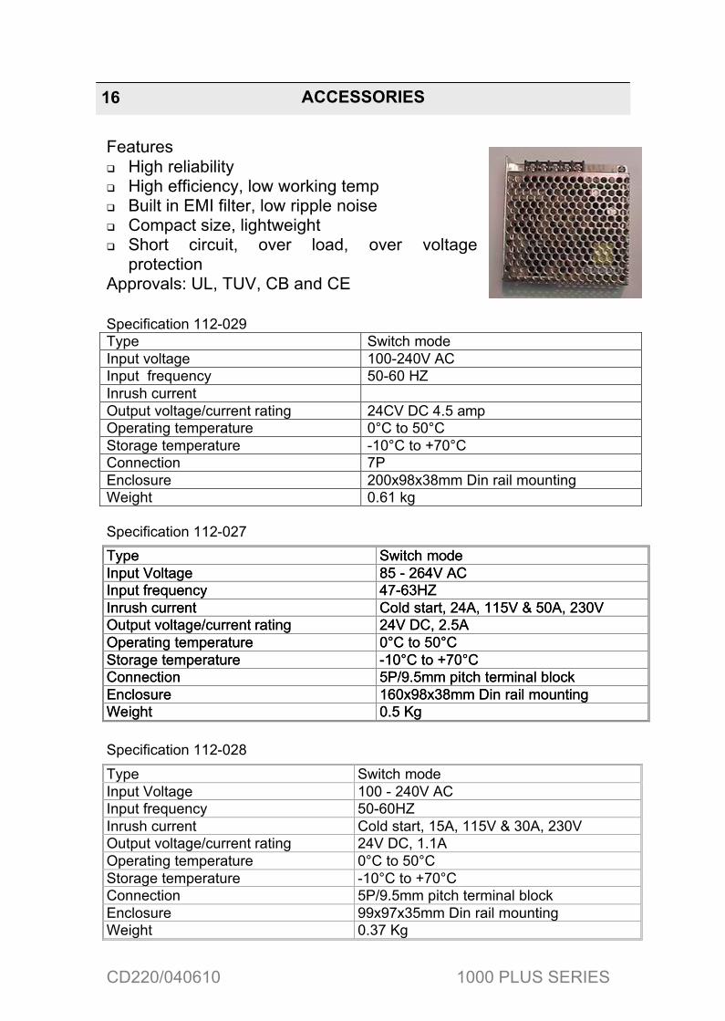
Features High reliability High efficiency, low working temp Built in EMI filter, low ripple noise Compact size, lightweight Short circuit, over load, over voltage
protectionApprovals: UL, TUV, CB and CE
Specification 112-029Type Switch modeInput voltage 100-240V ACInput frequency 50-60 HZInrush currentOutput voltage/current rating 24CV DC 4.5 ampOperating temperature 0�C to 50�CStorage temperature -10�C to +70�CConnection 7PEnclosure 200x98x38mm Din rail mountingWeight 0.61 kg
Specification 112-027
Specification 112-028
Type Switch modeInput Voltage 85 - 264V ACInput frequency 47-63HZInrush current Cold start, 24A, 115V & 50A, 230VOutput voltage/current rating 24V DC, 2.5AOperating temperature 0�C to 50�CStorage temperature -10�C to +70�CConnection 5P/9.5mm pitch terminal blockEnclosure 160x98x38mm Din rail mountingWeight 0.5 Kg
Type Switch modeInput Voltage 85 - 264V ACInput frequency 47-63HZInrush current Cold start, 24A, 115V & 50A, 230VOutput voltage/current rating 24V DC, 2.5AOperating temperature 0�C to 50�CStorage temperature -10�C to +70�CConnection 5P/9.5mm pitch terminal blockEnclosure 160x98x38mm Din rail mountingWeight 0.5 Kg
Type Switch modeInput Voltage 100 - 240V ACInput frequency 50-60HZInrush current Cold start, 15A, 115V & 30A, 230VOutput voltage/current rating 24V DC, 1.1AOperating temperature 0�C to 50�CStorage temperature -10�C to +70�CConnection 5P/9.5mm pitch terminal blockEnclosure 99x97x35mm Din rail mountingWeight 0.37 Kg
ACCESSORIES16

CD220/040610 1000 PLUS SERIES
Mirror Units
Two or three sides of a machine can be safeguarded with a single light curtain by using mirrors to deflect the light curtain’s infra-red beams. (see appendix 1 for installation guidance)
The Smartscan mirror system provides a sturdy floor mounting kit together with an aluminium column for mounting the mirror. The mirror assembly simply slots onto the column and can be adjusted to the height required for the application.
The special mounting stand enables the mirror unit to be rotated through 360 degrees while also allowing full adjustment in all axes.
Note: Mirrors cause a reduction in optical efficiency, reducing the effective range of the light curtain. Refer to appendix 1 for guidance.
Universal Mounting Column
Mirror Unit
Floor Stand
ACCESSORIES 17

CD220/040610 1000 PLUS SERIES
Range of the light curtain
Maximum range through 1 mirror
Maximum range through 2 mirrors
0.5m - 5m 4m 3m4m -10m 8m 6.5m
Mirror Units
Model number Description
044-252 600mm x 110mm wide mirror unit 044-249 900mm x 110mm wide mirror unit 044-250 1200mm x 110mm wide mirror unit044-253 1400mm x 110mm wide mirror unit
Mounting Columns and Floor Stands
Model number Description
044-256 1.1m aluminium universal mounting column044-257 1.3m aluminium universal mounting column044-258 1.6m aluminium universal mounting column044-247 1.8m aluminium universal mounting column044-262 2.0m aluminium universal mounting column044-248 Floor stand
ACCESSORIES18
Note: Mirror length must be a minimum of 100mm longer than the overall length of the light curtain to be installed.
Note: A universal mounting column and floor stand is required for each mirror unit.

CD220/040610 1000 PLUS SERIES
Mute signalling photocell Type 109-016
The polarised retro-reflective photocell can be used in conjunction with MFU 011-151 and MFU 155 to provide the mute initiating signals to terminals B3 and B4 of the MFU.
A safety light curtain with mute control function is often used in the packaging industry. In conjunction with a 1000 Plus Series light curtain and an MFU 011-155 two photocells are positioned to scan across a conveyor to detect loaded pallets prior to the load interrupting the light curtain. The photocell must be positioned to detect the load during the entire time the load is passing through the light curtain.
Type 109-016 photocell has a maximum sensing range of 4 metres.
Each photocell comes complete with mounting bracket and retro-reflective mirror.
Modelnumber Description
109-016 Polarised retro-reflective photocell kit
Sensing Distance 4mTransmitter Diode Infra-redSensing Adjustment NoneProtection Rating IP65Operating Voltage 12-240V dc, 24-240V ac - 50/60HzOutput RelayCurrent Consumption 2VA maxResponse Time 15msEnclosure Intensive ABSCable 1.5m lengthOperating Temp -20C to +60CHumidity 35% to 85%Weight 285g
ACCESSORIES 19

CD220/040610 1000 PLUS SERIES
Mute Signalling Photocell Type 109-006
The through-beam infra-red photocell can be used in conjunction with MFU 011-151 and 011-155 to provide the mute initiating signals to terminals B3 and B4 of the MFU.
A safety light curtain with mute control function is often used in the packaging industry. In conjunction with a 1000 Plus Series light curtain and an MFU 011-151 and 011-155 two photocells are positioned to scan across a conveyor, to detect loaded pallets prior to the load interrupting the light curtain. The photocells are positioned to scan across a conveyor, to detect loaded pallets prior to the load interrupting the light curtain.
Type 109-006 photocells have a maximum sensing range of 10 metres. Each transmitter and receiver comes complete with a 1.5m cable.
Modelnumber Description
109-006 Through-beam photocell kit
Sensing Distance 10mTransmitter Diode InfraredSensing Adjustment NoneProtection Rating IP65Operating Voltage 12-240V dc, 24-240V ac - 50/60HzOutput RelayCurrent Consumption 2VA maxResponse Time 15msEnclosure Intensive ABSCable 1.5m lengthOperating Temp -20C to +60CHumidity 35% to 85%Weight 285g
ACCESSORIES20

CD220/040610 1000 PLUS SERIES
Smartscan Remote Mounting Stackable Beacons
Remote Mounting Stackable Beacons
A range of Stackable Beacons are available.
They are typically used where the machine application requires visual indication of control functions from a single location. The translucent plastic lenses provide all round light visibility and can be programmed to provide either flashing or a steady output. The bright LED’s are supplied in a variety of colours as listed below.
Mounting Stands
Designed to accommodate our range of safety light curtains.
The Adjustable Stand (50mm x 50mm) offers the user a flexible mounting option. The stand has adjustable brackets that allow the safety light curtain to be mounted at different positions to suit a specific application. Brackets for mounting mute signalling photocells on the stand are also available.
The Channel Stand allows the user to mount the safety light curtain inside a protective housing. This provides protection on three sides to give a more robust installation. Channel stands would typically be used where the safety light curtain is at risk of damage from fork lift truck operations, or in the case of end-of-line applications damage from falling pallet loads.
Model number Description
105 - 801 High intensity LED stackable beacon kit - Red105 - 802 High intensity LED stackable beacon kit - Orange105 - 803 High intensity LED stackable beacon kit - Green105 - 804 High intensity LED stackable beacon kit - Blue105 - 810 Monitored mute beacon module
ACCESSORIES 21

CD220/040610 1000 PLUS SERIES
Adjustable Mounting Stands
Straight stands
Modelnumber Description Height
044 – 408 Pair of adjustable straight stands (with complete bracket set) 2m
ACCESSORIES22
CD220/040610 1000 PLUS SERIES
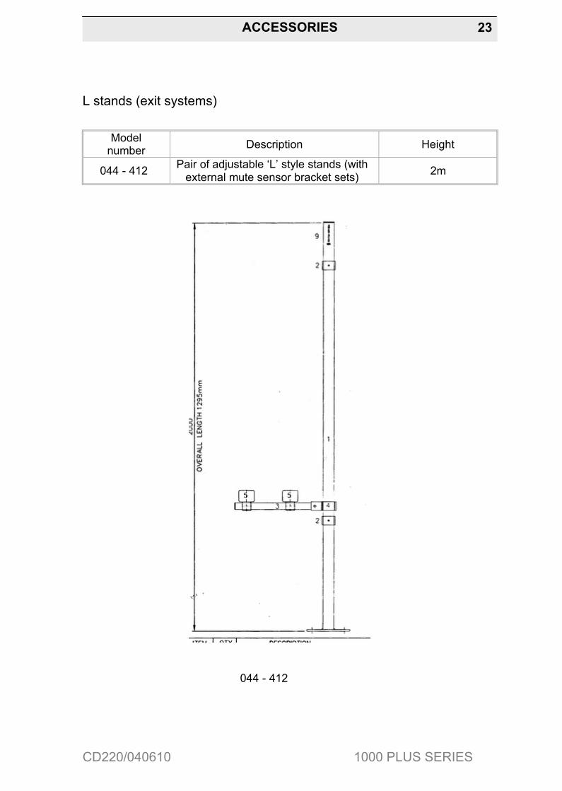
L stands (exit systems)
Modelnumber Description Height
044 - 412 Pair of adjustable ‘L’ style stands (with external mute sensor bracket sets) 2m
044 - 412
ACCESSORIES 23

CD220/040610 1000 PLUS SERIES
T stands (entry / exit systems)
Modelnumber Description Height
044 - 400 Pair of adjustable ‘T’ style stands (with external mute sensor bracket set) 2m
ACCESSORIES24
044 - 400

CD220/040610 1000 PLUS SERIES
Channel Mounting Stands
Straight stands
Modelnumber Description Height
044 - 118 Pair of channel floor stands (straight) 1.5m044 – 218 Pair of channel floor stands (straight) 2m
ACCESSORIES 25

CD220/040610 1000 PLUS SERIES
Safety System Solutions
Smartscan recognise the difficult balance that customers have to make between meeting Health & Safety legislation requirements and managing their demanding production needs.
Smartscan design and manufacture systems to meet the particular needs of their customer’s safety applications - from single machines to full production lines.
We provide our customers with a total service, from initial safety advice through to regular maintenance of their safety systems.
Expert Advice Risk AssessmentSafety System Design Product SpecificationSafety System Installation System Maintenance
SAFETY SYSTEMS SOLUTIONS26+

CD220/040610 1000 PLUS SERIES
Mirrors
Reflector mirrors can be provided enabling two or three sides of a machine to be safeguarded with, what is effectively a single light curtain.
When mirrors are employed it is essential that the mounting of the transmitter unit, receiver unit and mirrors themselves are sufficiently rigid. Alignment becomes increasingly critical as the range and number of mirrors increase. Mirrors cause a reduction in optical efficiency, reducing the effective range. A guide to the practicality of using mirrors is given below.
Range of the light curtain
Maximum range through 1 mirror
Maximum range through 2 mirrors
0.5m - 5m 4m 3m4m -10m 8m 6.5m
Total Light Path 1 Mirror 2 Mirror2m# Easy Easy4m* Easy Medium6m* Medium Hard8m* Hard Not Feasible
# Based upon a 012-105, * Based upon a 012-104
Note: Perimeter curtains will be easy to align, curtains over 900mm may be more difficult to align. Check with the Smartscan technical department prior to ordering for a particular application. [email protected], Tel: +44 (0) 1536 401313, Fax : +44 (0) 1536 268354
Note: The angle of the light curtain striking the reflective surface must be within defined limits.
APPENDIX 1 27

CD220/040610 1000 PLUS SERIES
Alignment though one mirror
1. Secure the transmitter, receiver and mirror units in the position in which they are intended to be used.
2. Ensure all units are perfectly upright in all planes by using a sprit level.
3. If the units are floor mounted on stands ensure the floor is even. Shim the floor mounts if necessary to ensure the units are all upright.
4. With one eye looking over the top of the receiver unit in line with the centre of the extrusion look towards the reflective surface of the mirror, in a similar manner to looking through a gun sight.
5. A second person must adjust the mirror to the left and right until the Perspex window of the transmitter unit can be seen reflected in the mirror.
6. If the light curtain is scanning over a long range it may be difficult to see the reflection of the transmitter units Perspex window in the mirror. If so, cut a piece of white paper to the size of the Perspex window and mount directly in front of the window. Now repeat step 5.
7. If the reflection of the white paper is difficult to see in the mirror then employ a third person to hold a flashlight in front of the transmitter unit with the light beam pointing directly in line with the Perspex window towards the mirror. Now repeat step 5.
8. Use shims to ensure the mirror is accurately aligned to enable the infra red beams in the lightcurtain to reach the receiver.
Alternatively, fabricate mirror mountings to include some form ofadjustment to enable movement both left and right and also forward end backwards from the central axis of the mirror.
APPENDIX 1 28

CD220/040610 1000 PLUS SERIES
Alignment though two mirrors
9. Follow instruction 1-4
10. A second person must adjust the position of the first mirror to the left and to the right until the entire length of the second mirror is reflected in the first mirror. If difficulties are experienced in seeing the reflection on the second mirror in the first mirror then use a piece of white paper cut to size and position in front of the second mirror.
11. If the reflection of the white paper is difficult to see in the first mirror then employ a third person to hold a flashlight in front of the second mirror with the light beam pointing directly in line with its mirror housing towards the first mirror. Secure the first mirror.
12. Again follow instructions 1 to 4.
13. The second person must adjust the position of the second mirror to the left and to the right until the entire length of the transmitter unit is reflected through both the first mirror and the second mirror. If difficulties are experienced in seeing the reflection of the transmitter unit through both the first then the second mirrors then use a piece of white paper cut to size and position in front of the transmitter unit.
14. If the reflection of the white paper is still difficult to see through the first and second mirrors then employ a third person to hold a flashlight in front of the transmitter unit with the light beam pointing directly towards the second mirror. Secure the second mirror.
15. Ensure the mirrors are directly aligned thus enabling the infra red beams of the transmitter to reach the receiver.
APPENDIX 1 29

CD220/040610 1000 PLUS SERIES
15 Alternatively, fabricate mirror mountings to include some form of adjustment to enable movement both left and right and also forwards and backwards from the central axis of each mirror.
16. Now turn on the power to the light curtain and check that the green LED beam indicator, mounted on the receiver unit is ‘on’. If not, it may be necessary to finely adjust each mirror in turn to ensure the infa red energy from the transmitter unit is being reflected through the mirror(s) to the corresponding receiver unit.
Alignment of the light curtain using mirrors
With 1 Mirror
Note: The mirror length must be a minimum of 100mm longer than the overall length of the light curtain to be installed eg. 50mm above and 50mm below either end of the light curtain
APPENDIX 1 30