smartrack - etc · smartrack is a revolutionary concept in professional digital dimming equipment,...
TRANSCRIPT

smartrackUSER MANUAL
Electronic Theatre Controls Ltd.5 Victoria Industrial Estate, Victoria Road
London W3 6UU, England(+44) 181 896 1000 FAX (+44) 181 896 2000
Copyright 1995 Electronic Theatre Controls Ltd.Specifications subject to change. Revised 8/952000M1001

smartrack
User Manual
page i
Introduction – Please read this first
Thank you for choosing ETC Smartrack digital dimmers. We aresure that you will be pleased with Smartrack, and wish you along and happy association with our company and its products.
We at ETC have done everything we can to ensure that yournew dimming system will function perfectly, will be easy toinstall, and will give you many years of reliable service.
This manual contains detailed instructions for installing, usingand maintaining ETC Smartrack dimmers. Please follow themcarefully, to guarantee best results. Neither ETC Ltd nor itsdistributors can accept any liability whatsoever arising from theguidelines in this manual not being followed.

Table of contents1. Digital dimming explained ...................................................1
2. About Smartrack..................................................................22.1 Mechanical............................................................................22.2 Electrical................................................................................42.3 Filtering .................................................................................4
2.3.1 Standard risetime choke ..........................................................42.3.2 High risetime choke ................................................................5
2.4 Rack control ...........................................................................52.4.1 Dimmer profile .......................................................................52.4.2 Response speed......................................................................52.4.3 Dimmer test ............................................................................62.4.4 Reference voltage ...................................................................6
2.5 Thermal management ..............................................................6
3. Getting Started – What’s in the box......................................83.1. Smartrack ..............................................................................8
3.1.1 Rack .....................................................................................83.1.2 Power assemblies ...................................................................9
4. Installation.........................................................................104.1. Environmental considerations .................................................104.2. Planning and marking out ......................................................10
4.2.1 Marking out a wall ...............................................................114.2.2 Planning an island installation ................................................12
4.3. Wall fixings .........................................................................124.4. Assembly and mounting.........................................................124.5. Power wiring........................................................................14
4.5.1 Standard Smartrack ..............................................................164.5.2 Connecting single and bi-phase systems ..................................174.5.3 Connecting Delta systems ......................................................17
page ii
Smartrack User Manual ETC Ltd

4.5.4 Cascading a stack of Smartracks ...........................................174.6. Load wiring..........................................................................19
4.6.1 Installing load wires ..............................................................194.7. Identifying and testing power and load wiring..........................194.8. Signal wiring .......................................................................204.9. Power assemblies .................................................................21
4.9.1 Installation ...........................................................................214.9.2 Connecting load wiring .........................................................214.9.3 Connecting power wiring – RCD option fitted...........................234.9.4 Connecting power wiring – without RCD option .......................254.9.5 The power assembly signal looms ...........................................25
4.10 Smartrack door ....................................................................274.10.1 Mounting the door ................................................................274.10.2 Connecting earth and power wiring........................................274.10.3 Smartrack CPU jumper settings ...............................................274.10.4 Connecting power assembly signal looms................................284.10.5 Connecting DMX input/output wiring ......................................294.10.6 Fitting blanking plates ...........................................................294.10.7 Closing the door...................................................................294.10.8 Fitting dimmer number strips ..................................................30
5. Commissioning and configuration.......................................315.1. Switching on ........................................................................315.2. Power and signal indicators ...................................................315.3. Modular Smartrack dimmer level indicators..............................325.4. Battery supported memory .....................................................335.5. Using offline mode................................................................33
5.5.1 Verifying rms line voltage in offline mode ................................345.5.2 Setting the output voltage range in offline mode .......................34
5.6. Testing dimmer circuits with the rotary potentiometer .................355.7. DMX control.........................................................................35
5.7.1 Terminating the DMX line.......................................................36
page iii
Smartrack User ManualVersion 1.2

5.7.2 Good/bad data ...................................................................365.7.3 Setting the rack address ........................................................365.7.4 Large installations .................................................................375.7.5 Testing dimmers with DMX.....................................................37
5.8. Dimmer profiles ....................................................................375.8.1 What is a profile?.................................................................375.8.2 Smartrack standard profiles ...................................................385.8.3 Dimmer and console set profiles .............................................395.8.4 Setting profiles .....................................................................39
5.9. Response speed....................................................................405.9.1 Setting response speed..........................................................41
5.10 Important note – Exiting from user interface mode.....................41
6. Smartrack operational summary ........................................426.1. Accessing the control panel....................................................426.2. Address setting.....................................................................436.3. Dimmer mode ......................................................................43
6.3.1 Testing dimmers at levels .......................................................436.3.2 Profile mode.........................................................................446.3.3 Speed mode ........................................................................44
6.4. Offline mode........................................................................456.4.1 Checking line voltage............................................................466.4.2 Setting the output voltage scale ..............................................466.4.3 Clearing configuration settings ...............................................46
7. Routine maintenance..........................................................477.1. Torque settings .....................................................................47 ...
7.2. Cleaning .............................................................................477.3. Inspecting dimmer module connectors .....................................487.4. Control fuse ratings...............................................................487.5. Battery replacement ..............................................................48
page iv
Smartrack User Manual ETC Ltd
8. Technical support ...............................................................498.1. Who to call..........................................................................498.2. What to tell them ..................................................................49
9. Accessories and options .....................................................509.1 RCD protection .....................................................................509.2 Single phase adapter kit ........................................................509.3 Spare numbering sheets ........................................................519.4 Load terminal extender kits.....................................................51
10. Spare parts ........................................................................52
page v
Smartrack User ManualVersion 1.2

Notes:
page vi
Smartrack User Manual ETC Ltd

smartrackUSER MANUAL
1. Digital dimming explainedThere are good reasons why users of professional dimming equipment are now onlywilling to accept true digital dimming equipment, such as ETC Smartrack andSmartpack. They are:
Accuracy – digital dimmers are able to regulate output levels to reproduce preciselyrecorded intensities, even when mains power is fluctuating.
Reliability – with fewer electronic components, digital dimmers literally have lessthings to go wrong.
Smarts – with processing power on board, digital dimmers can perform tasks previ-ously impossible with analogue techniques. These include diagnostic functions, indi-vidual dimmer profile and response speed settings, and more.
Cost – a well designed digital dimmer typically uses fewer electronic componentsand is therefore cheaper to manufacture.
The key to the accuracy of digital dimmers is regulation. This means that the dimmer isconstantly measuring the rms voltage of each supply phase (a total of 12,800 times persecond in the case of ETC Smartrack) to build up an accurate picture of the condition ofthe mains supply to each dimmer. Using this information, the power devices are pre-cisely controlled, to compensate for any mains voltage fluctuations and produce a con-stant voltage output for any given control level.
Of course, in an age where virtually all lighting control consoles output the same inter-nationally accepted digital control signal (USITT DMX512), another plus with digitaldimmers is that no expensive demultiplexer stage is required. The digital signals fromthe lighting console are simply connected directly to the dimmers.
page 1

2. About SmartrackSmartrack is a revolutionary concept in professional digital dimming equipment, offer-ing a very wide range of system options in an extremely compact package, with manysignificant advantages over its competitors:
Compact size
Competitive price
Easy and economical installation
Highly flexible configuration options
Basic or modular variants
All-digital – high reliability, high accuracy
Smartrack is unique in that it offers competitive system solutions at all levels of the market,and versions exist to cover all requirements, right up to top level broadcast applications.
2.1 Mechanical
Each Smartrack is a proprietary wall mounting steel cabinet, measuring 85cmwide, 65cm high and 30cm deep, designed to house up to three power assem-blies (supplied separately), each of which comprises 30kW of dimming, as either12 x 2.5kW, 6 x 5kW or 3 x 10kW. A hinged steel front door supports all thesystem electronics, and the rack is available in two versions, to accept eitherbasic (hard-wired) or plug-in modular power assemblies.
Smartrack is primarily intended for wall-mounting, and may be installed up tothree high, side by side, or back to back. Smartrack may also be fitted into flight-cases with custom rear connector panels, for highly cost-effective mobile dimmingsystems.
All power, load and signal cables may enter from top, bottom, or through rearpanels and sufficient space is provided for through wiring in a stack of threeSmartracks. Front access only is required for installation and maintenance, andall terminal screwheads face forward, for easy re-tensioning in service.
page 2
Smartrack User Manual ETC Ltd

Power Assemblies are available either with plug-in modules containing powerdevices and LED level indicators, or with power devices mounted on a perma-nent heatsink. Power assemblies of different ratings may be mixed in a rack, butbasic and modular power assemblies may not be mounted in the same rack.
All controls for rack configuration are mounted on the front panel, and the startaddress of the rack is normally displayed, along with power, DMX and thermalstatus indicators.
page 3
Smartrack User ManualVersion 1.2
DIGITAL
SmartRack
2.5 2.5 2.5
2.5 2.5 2.5
2.5 2.5 2.5
0 205 490 850
0
84
290
496
650
mcb centre
mcb centre
mcb centre
Front view of a modularSmartrack, showing key
dimensions.Note that Smartrack is
300mm deep, plus 30mmfor dimmer module handles
on the modular version only.
smartrack
215 630 990

2.2 ElectricalSmartrack is designed for operation on single or three phase supplies at 230Vac±12.5%. Delta versions are also available to special order.
Each Smartrack may optionally be supplied with a 4-pole 125A or 160A circuitbreaker fitted, and earth leakage (RCD) protection may be fitted at power assem-bly level (single phase to special order).
Power devices are generously overrated solid state switching devices, encapsu-lated into quad 2.5kW, dual 5kW and single 10kW modules.
Individual dimmer circuits are normally protected by single pole miniature circuitbreakers, rated at 13A (2.5kW), 25A (5kW) and 50A (10kW). Single pole withneutral disconnect mcbs and double pole mcbs are also available to specialorder. See the Smartrack specification for more detailed electrical information.
2.3. FilteringSmartrack dimmers are designed to conform to the EMC requirements ofEN55014 and EN55022, the usually accepted European norms specifying RFIinterference suppression requirements. In addition, low frequency filtering isachieved to different levels, depending on the choke specified. Two differentchoke styles are available, offering different current risetimes, as required for dif-ferent types of work. Generally speaking, the higher the risetime the more theinterference generated by the dimmer is suppressed, but it is unwise to specify ahigher risetime than that actually required, since there are weight, thermal andcost penalties as you go up the scale.
2.3.1 Standard risetime choke
The standard choke is wound on a 2.5” toroidal iron powder core, andproduces a risetime in excess of 200µS. This should be adequate for the-atre and most video production work, and complies with the BBC’sPID171 standard for 2.5kW dimmers.
page 4
Smartrack User Manual ETC Ltd

2.3.2High risetime choke
The High Risetime choke is wound on a 4” toroidal iron powder core, andproduces a risetime in excess of 400µS. This is a requirement of theNordic Television Authorities for 2.5kW dimmers, and complies with theBBC PID171 standard for 5kW and 10kW dimmers. It is recommendedfor front of house lighting circuits in theatres and in concert halls, whereacoustic requirements may be critical.
2.4. Rack control Smartracks receive USITT DMX512/1990 dimmer drive signals from a very widerange of lighting controllers, including all ETC Expression, Impression, Insight,MicroVision, Connection and Reflection systems.
The control panel on each Smartrack enables the user to set and display a startaddress for the rack, as well as to select, for each or all dimmers:
2.4.1Dimmer profile
Any dimmer may be set to any one of 12 preprogrammed curves, includ-ing three non-dims and a ‘hot’ setting (permanently on). This should takecare of the requirements of the vast majority of entertainment and architec-tural applications, and custom profiles may be generated if required.
2.4.2Response speed
A dimmer’s response speed is the time it takes for the dimmer’s output toarrive at a new level, following the reception of a new level instruction bythe dimmer’s control electronics, and is measured in milliseconds. Don’tconfuse response speed (in milliseconds) with risetime (in microseconds).
Smartrack ships with a default 100mS response speed set for all dimmers,but allows the user the choice, for any or all dimmers in a rack, of 30,100, 300 or 500mS.
Thus, a studio with RCDs and a lot of 5kW loads might function happilywith all dimmers set to 300mS response time, while individual circuits for
page 5
Smartrack User ManualVersion 1.2

chasers or practicals might be set to 30mS for special effects work. A tour-ing rack used for concert lighting, on the other hand, might be set globallyto 30mS, but with the odd 10kW dimmer at 500mS.
IMPORTANT: A slower response speed will also have beneficial effects onlamp life, since the shock to cold filaments will be reduced, as the timeperiod required to ramp them to full brightness is increased.
2.4.3Dimmer test
Any or all dimmers may be selected and set to a level, using the rotarypotentiometer on the front panel. The dimmers in a rack may be ‘flashedthrough’ to a level, by setting the pot to the desired intensity, and steppingthrough the dimmers using the or buttons.
2.4.4Reference Voltage
Smartrack needs to know the voltage expected by the user for full on(100%), to which all other levels are scaled. This reference voltage is setby the user or installer, using the rack controls.
2.5. Thermal ManagementSmartrack runs remarkably cool, and uses computer controlled brushless dc fansto do so with minimum noise and maximum fan life. One fan is incorporated intothe end of each power assembly, and air is drawn very efficiently over thechokes and power device heatsinks before being exhausted through the frontpanel.
Since Smartrack’s air inlet and exhaust vents are all on the front panel, there isno problem stacking Smartracks vertically and horizontally, or mounting in sim-ple flightcases.
page 6
Smartrack User Manual ETC Ltd

One thermal sensor is provided for each power device, and constantly feedsback temperature status information to the central processor (CPU). The CPU usesthis information to decide when it is necessary to switch on the fan for any givenpower assembly. In the event that a power device should run hot, an amberwarning signal is lit on the front panel. If the device overheats, it will be shutdown, and the warning LED will flash red.
The thermal indicator LED may be wired to a remote panel, or incorporated incontrol room furniture, to provide a simple (geographic) dimmer room mimicpanel, showing rack power and temperature status.
page 7
Smartrack User ManualVersion 1.2

3. Getting started – what’s in the box
3.1. SmartrackSmartrack systems are shipped broken down into racks and power assemblies(up to three per rack). Please check carefully to verify that you have everythingyou need before starting the installation.
3.1.1RackEach rack is shipped separately as an empty enclosure, with separatelywrapped door assembly and a number of internal fittings kits, namely:
Metalwork Kit2 x power cable entry cover2 x load cable entry cover
Hardware KitDoor Kit2 x M4 black washer1 x M4 shakeproof washer1 x M4/10 Pan Posi Screw1 x graphics layer number sheetEntry Cover Kit32 x M4/6 taptite screw32 x M4 spring washerFan Kit3 x M5/10 Pan Posi screw3 x M5 nylon washerFoot Kit4 x plastic feet 4 x M5/16 csk screws4 x plastic plugsPower Terminal Safety Cover Kit1 x Plastic Safety Cover3 x M5/12 taptite screw
Remove the door assembly from the carton and store it separately whilethe racks are installed and wired. It’s not needed until the installation ofthe wiring and power assemblies is complete.
page 8
Smartrack User Manual ETC Ltd

3.1.2Power assemblies
Power assemblies are packed individually, and are of two main types –basic or modular. Basic power assemblies come with the power devicespermanently mounted on a single heatsink on the front of the assembly.
Modular power assemblies are each provided with three plug-in dimmermodules containing the power devices and level indicators.
When installing modular power assemblies, first remove the plug-in mod-ules and store separately in a safe place until ready.
Each power assembly is also shipped with
Power Loom Kit
1 x 2.5mm2 cable. Brown ident L11 x 2.5mm2 cable. Brown ident L21 x 2.5mm2 cable. Brown ident L31 x 2.5mm2 cable. Blue ident N1 x 2.5mm2 cable. Yellow/green ident
Hardware Kit5 x M5/10 Hex head screw6 x M5 shakeproof washer1 x M5/10 Pan Posi screw2 x 10mm2 uninsulated bootlace ferrules
Note that the power assemblies are not required for the first stages ofinstallation, and should be left in their packing, especially if there is a riskof builders’ dust on site.
page 9
Smartrack User ManualVersion 1.2

4. InstallationSmartracks are intended for mounting either against a wall, back to back in an islandformation or in a flightcase. This section deals with wallmount or island installation –see the next section for information on flightcasing.
4.1. Environmental considerationsCare must be taken to ensure that the ambient temperature in the dimmer roomstays within the range 0 – 35° Celsius. In some cases, this will require air extrac-tion or air conditioning.
In order to calculate worst case air handling requirements, you need to know thethermal losses in the dimmer, as well as estimating the actual maximum continu-ous load. Since lighting loads vary enormously, it may be reasonable to apply adiversity factor of between 0.5 – 0.8 to the actual connected load, to representworst case.
The formula for calculating the heat generated by the dimmers (in watts) is there-fore:
Total connected load x diversity factor x (100 – efficiency %)Or, for example:
250,000 x 0.6 x (100 – 98%) = 3,750 watts
Here, a diversity factor of 0.6 is applied to a 250kW load, assuming 98% effi-ciency at the dimmers (which is reasonable). The result is that up to 3.75kW ofheat may be anticipated in the dimmer room, which may then need additionalextraction or cooling.
Relative humidity should be kept below 80%, non-condensing.
4.2 Planning and marking outSmartracks are intended to be mounted up to three racks high, and as wide asmay be required, with no air gap between racks.
Wiring access may be from above, from below or through the rear, and onlyfront access is required for installation and service.
page 10
Smartrack User Manual ETC Ltd

We recommend using a large cable duct running across the top of a bank ofSmartracks, carrying power and load wiring. Alternatively, power wires may berun in from below, and load wires from above, or vice versa.
Note that DMX signal wires should be run in separate cableways from the powerand load cables, outside the racks, though it is permissible to mix them in theimmediate vicinity and inside the racks themselves.
4.2.1Marking out a wall
Use the dimensions below to mark out a grid on the wall where theSmartracks are to be installed. Note the height and width of the racks andthe mounting centres:
page 11
Smartrack User ManualVersion 1.2
850
760 9045
850
760
560
560
560
90
90
58
663
650
650
FixingCentres
Stack 1 Stack 2
Two stacks of threeSmartracks, showing posi-
tions of fixing holes. 13mmhas been allowed for the
feet at the bottom of eachstack, which are optional.
Rack:h 650mm, w 850mm
Mounting centres:h 560mm, w 760mm

4.2.2Planning an island installation
Smartracks may be mounted back to back, either in an island, or, withone end of each bay against a wall, in a peninsula configuration.
On a solid floor, all wiring will normally be taken out through the topwiring access ports. Where raised computer type flooring is used, some orall of the wiring may enter through the base of the racks.
Note that the ‘keyhole’ fixing positions in the back of each rack must beused in back-to-back installations, to provide stability. Use M6 nuts andbolts to fix back-to-back racks together.
A knockout panel is provided in the centre of Smartrack’s rear panel,which may be removed if interwiring between back-to-back racks isrequired. If using the knockout panels, use a grommet strip around theinside edges to prevent chafing.
4.3. Wall fixingsEach Smartrack weighs between 75-85kg, depending on version used, and isfixed to the wall at four points. Making an allowance for cable of 20-25kg perrack, this means that each fixing has to support no more than 30kg. The actualfixing used will depend very much on the wall material and condition, but on abrick or concrete wall, 50 x 5mm woodscrews, used in conjunction with correctlyinstalled plastic wall plugs, should be more than sufficient.
On uneven surfaces, it may be necessary to mount 50 x 50mm wooden battensto the wall, and fix the Smartracks to the battens. In this case, ensure that the bat-ten fixings are sufficient to take the total weight of all the Smartracks to be somounted.
Having marked out the wall, drill, plug and fit mounting screws, protruding about20mm from the wall.
4.4. Assembly and mountinga) If the bottom Smartrack in a stack will stand on the floor, fit the four plastic
feet provided by screwing them up into the threaded inserts on the base ofthe rack.
page 12
Smartrack User Manual ETC Ltd

page 13
Smartrack User ManualVersion 1.2
How to fix two Smartrackenclosures together.
Fit power and load cableentry cover plates to top and
bottom of the stack asrequired, but not in between
Smartracks in a stack.
Plastic plugs (f)
M5 Fixing screws (d)
Plastic feet (a)and M5 fixingscrews
Mounting 'keyholes' (c)

b) If required, fit the bottom cable entry cover plates provided to the base of thebottom Smartrack, using the taptite screws provided. These plates should beused if forming or glanding is required, or, unworked, to blank unused cableentry ports.
c) Hook the bottom Smartrack in each stack onto the four fixing screw headsalready in the wall, locating the four ‘keyholes’ in the rear panel to thescrews in the wall. Partially tighten screws.
d) Fit the upper Smartrack(s) in the stack to the wall fixing screws in the sameway, then, using the M5 screws provided, fix the racks in the stack togetherby screwing into the threaded holes in the upper rack(s), through the match-ing clearance holes in the rack(s) below.
e) Tighten all wall fixing screws.
f) Fit the four plastic plugs provided into the four holes in the top surface of thetop Smartrack in each stack.
g) If required, fit the top cable entry cover plates to the top surface of the topSmartrack, using the taptite screws provided. These plates should be used ifforming or glanding is required, or, unworked, to blank unused cable entryports.
4.5. Power wiringSmartrack is primarily intended for use on five wire services, where the phase toneutral voltage is 230Vac ± 12.5%. However, single phase and delta wiring isalso possible, and the various alternatives are dealt with below.
The current draw of any dimmer rack is hard to predict, and is always subject tomajor variances. A reasonable way of assessing the current requirement perphase is:
Total connected load (watts) x Diversity factor (0.5 – 0.8)(voltage x 3)
Estimating the diversity factor is a matter of judgement, and depends very muchon the type of installation and its working practices. It may also be that the instal-lation as a whole may have a diversity of 0.5, while individual racks may expect0.8 or even higher.
page 14
Smartrack User Manual ETC Ltd

page 15
Smartrack User ManualVersion 1.2
L1
L3
L2
N
Wiring in power feedercables to a standard
Smartrack.Note that power wiring to
other Smartracks in a stackshould be tied back to thecable way provided downthe inner left wall of the
enclosure.

NOTE: If the mains circuit breaker option (MCCB) is not fitted, adequate protec-tion must be installed upstream of the Smartrack(s).
4.5.1Standard Smartrack
Standard racks require a five wire supply, terminated in eyelet (ring) lugs,to fit the M12 terminal screws provided.
a) Run the power wires into the power terminal block, via the top or bot-tom cable entry on the left side of the rack. Cable tie anchors are pro-vided just inside the cable entry ports.
Note that a cable way, with slots for cable ties, is provided to leadpower wires up and down the left side of the enclosure to feed otherSmartracks above or below.
b) Trim to length and terminate with M12 clearance lugs. Do not fit theplastic terminal block cover at this stage.
page 16
Smartrack User Manual ETC Ltd

page 17
Smartrack User ManualVersion 1.2
4.5.2Connecting single phase systemsSmartracks (without MCCBs) may be connected to single phase supplies, ifa single phase adapter kit (part number Y2.SR002.0) is used.
The kit comprises two nickel plated copper plates, which replace the exist-ing L1, L2, L3 & N terminals (single phase use only). See diagram.
One plate is fixed across the L1 & L2 studs with the nine equi-spaced holesto the right; these are connected to the bottoms of the channel circuitbreakers with the standard set of live cables.
The other plate is fixed across studs L3 & N with the three large holes tothe right. These connect to the neutral terminal block (located to the rightof the channel circuit breakers) with the three heavy cables provided in theadaptor kit.
Having fitted the plates, installation is as for standard Smartracks (seeabove).
Y2.SR002.0 contents:2 x plates3 x neutral cables (35mm2)3 x earth cables (16mm2)
4.5.3Connecting Delta systems
Power wiring is as for standard Smartracks, except that the neutral termi-nal is unused.Warning: only Smartracks supplied to operate on deltapower can be connected to delta power supplies.
4.5.4Cascading a stack of Smartracks In a stack of two or three Smartracks, it may be preferred to protect thewhole stack from one offboard circuit breaker or switchfuse. In this case,wire from the switch to the first rack (top or bottom, as convenient), thenmake up short power cables to link from the power terminal block in thefirst rack to the second, and so on.

page 18
Smartrack User Manual ETC Ltd
L1
L3
L2
N
Wiring a standard Smartrackfor single phase operation,using the Smartrack single
phase adaptor kit.

4.6. Load wiringAll load wiring enters the Smartrack(s) by either the top or bottom load entry portin the large centre section of the rack. Smartrack is primarily designed for loadwiring with single core cables in cableways, but may also be wired with threecore or multicore cables.
4.6.1 Installing load wires
Run in all load wires for each Smartrack or stack of Smartracks throughthe top or bottom load cable entry port. Columns of cable tie anchors areprovided, for earth, neutral and phase wires respectively (see diagram).
Bunch wires together and tie bunches to cable tie anchors, peeling off thewires for each power assembly at the appropriate row of cable tieanchors. Trim to 33cm from the cable tie anchor to the cable end.
If multicore cables are used, distribute them evenly across the cable tieanchors provided, and allow enough length at each power assembly levelto strip back the outer sheath sufficient to reach all terminals (allow 80cm).
Ensure that all wires are correctly labelled with circuit number and function(phase, neutral or earth).
4.7. Identifying and testing power and load wiringIt is essential that all power and load wiring be correctly identifiedand tested using a high voltage insulation tester, before installingpower assemblies or Smartrack electronics.
Use a low voltage tester to identify load pairs, and label accordingly, prior tocarrying out a high voltage insulation test.
Inspect for polarity and carry out a high voltage insulation test on all power feedwiring.
Do not attempt a high voltage insulation test with any Smartrackassemblies connected as this will destroy electronic components ineither the power assemblies or the control electronics.
page 19
Smartrack User ManualVersion 1.2

page 20
Smartrack User Manual ETC Ltd
4.8. Signal wiringSmartrack uses the international digital dimmer standard USITT DMX512 (1990)to receive dimmer drive signals from a controller. DMX wiring requires twistedpair and overall screen cable (Belden 9841 or equivalent), rated for RS485.
The signal cable loops from rack to rack, and will be terminated to the electron-ics on the front door. For the time being, run the cable continuously through theracks, using the power wiring chamber, allowing about 1m of slack for termina-tion in each rack.
L1
L3
L2
N
Laying in the load wires.Note the arrangement of
wires into Earth, Neutral andphase wires, according to
the phase of the load circuit(P1, P2 or P3). Laying the
wires in this way makesconnection to the load
terminals on the powerassembly easy and quick.
If using three core ormulticore cables, spread
them evenly across the ninecable bunches, and strip
back the outer insulation tothe cable tie.
Load wiring for other racksin the stack should be
bundled with the wiresshown, and passed through
the cable port to the rackabove or below, then laid in
as shown.
Earth Neutral PhaseP1 P2 P3 P1 P2 P3 P1 P2 P3
Cut c
able
to 3
3cm
from
cable
tie
Trim
insula
tion
6mm

page 21
Smartrack User ManualVersion 1.2
Note that, while signal cables should be kept away from power and load cablesin cable runs outside the rack(s), no harm will be done by their close proximityinside the Smartrack enclosure.
4.9. Power assemblies
4.9.1 Installation
a) Unpack the power assemblies. If installing modular power assemblies,set the plug-in modules aside in a safe place.
b) Remove the fan plate from the Smartrack, by releasing the three fixingscrews and pulling the fan plate towards you.
c) Starting with the bottom position in the Smartrack, slide in the powerassembly, with the circuit breakers to the left. Ensure that all the loadwires to be connected to the power assembly are laid over the top ofthe power assembly, and do not fall behind it.
d) Fix the power assembly in place by screwing the left side into thethreaded hole in the back of the rack’s power assembly slot, using theM5 screw provided. Do not fix the right side for the time being.
e) Repeat steps (b) to (d) for the middle and top power assemblies.f) Slide the fan plate back into position, ensuring that the tabs on the
three blades of the fan plate locate in the bases of the three powerassemblies. Fix the fan plate back in position with the three fan platefixing screws, and plug the fan cable plugs into the receptacles on theface of each power assembly (in part-populated racks, there is noneed to plug in the fan connector where no power assembly is pre-sent).
4.9.2Connecting load wiring
Carry out the following steps for each power assembly. If the wires arecorrectly laid in the back of the Smartrack, they should line up well withthe load terminals on the face of the power assembly.

page 22
Smartrack User Manual ETC Ltd
Please note the following maximum cable sizes:Earth and Neutral bars: 10 x 10mm2, 3 x 16mm2
2.5kW Phase terminals: 4mm2
5kW Phase terminals: 6mm2
10kW Phase terminals: 35mm2
It is occasionally necessary to use larger cable sizes on the 2.5kW and5kW dimmers, and an adapter kit is available, with 10mm2 and 16mm2
DIN terminals for oversized cables. See section 10.7 for part numbers.
Note that bootlace ferrules are required to be fitted to the earth and neu-tral wires if stranded cable is used.
a) Terminate load earth wires into the earth busbar on the left side of thepower assembly. Recommended tightening torque 1.5Nm (2.5mm2
cable) to 2Nm (10mm2 cable).
L1
L3
L2
N
2.5 2.5 2.5
2.5 2.5 2.5
2.5 2.5 2.5
Terminating load wiring.Note that numbering is
always from left to right, ie:Earth 1–12, Neutral 1–12,Phase 1–12. The same rule
applies to 3x10kW and6x5kW Power Assemblies.
Tip:It's easier to fit the
bottom PowerAssembly first,
terminate the loadwiring, then fit the
middle PowerAssembly, and so on.

page 23
Smartrack User ManualVersion 1.2
b) Terminate load neutral wires into the neutral busbar in the middle ofthe power assembly. Recommended tightening torque 1.5Nm(2.5mm2 cable) to 2Nm (10mm2 cable).
Note that bootlace ferrules are recommended if stranded cable isused.
c) Terminate the load phase wires into the three groups of output termi-nals. Recommended tightening torque 1Nm (2.5kW dimmers), 2Nm(5kW dimmers), 1.2Nm (10kW dimmers).
4.9.3Connecting power wiring – RCD option fitted
Each power assembly has to be connected to the power terminal block,using the part-assembled power loom provided. There are slight differ-ences, depending on whether the power assembly is fitted with RCD pro-tection or not. If not, skip to the next section.
a) Terminate the five wires to the appropriate terminals on the power ter-minal block, using the M5 hex-head screws provided. Recommendedtightening torque 2Nm. The colour code is L1 – L3 brown, Neutrallight blue, Earth green/yellow. Form the five wires into a loom, andrun to the top of the power assembly’s RCD.
b) Trim to length and terminate the three phase and one neutral wire intothe RCD’s caged terminals, in sequence (from the left):
L3 – L2 – L1 – N
Recommended tightening torque 2Nm.
c) Trim to length and terminate the earth wire into the left position of theearth bar, entering from below. Use the bootlace ferrule provided toprotect the stranded cable and ensure good earth contact.Recommended tightening torque 2Nm.

page 24
Smartrack User Manual ETC Ltd
L1
L3
L2
N
Wiring the power feeds fromthe power terminals to thePower Assembly RCD. Notethe order of connection to
the RCD.For the sake of clarity, only
one Power Assemblyconnection is shown.
L1L2L3 EN
page 25
Smartrack User ManualVersion 1.2
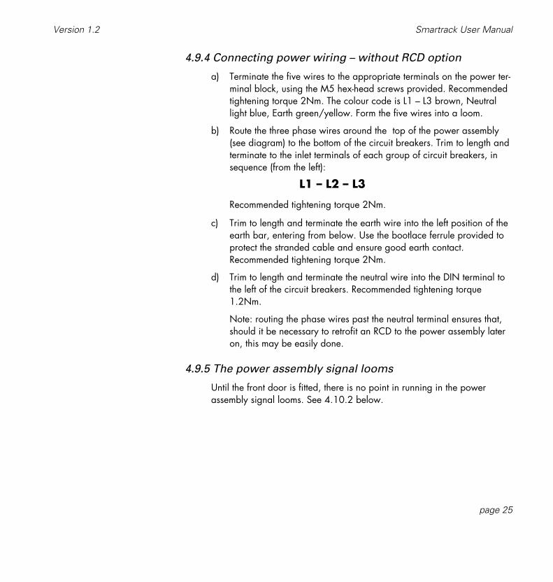
4.9.4 Connecting power wiring – without RCD option
a) Terminate the five wires to the appropriate terminals on the power ter-minal block, using the M5 hex-head screws provided. Recommendedtightening torque 2Nm. The colour code is L1 – L3 brown, Neutrallight blue, Earth green/yellow. Form the five wires into a loom.
b) Route the three phase wires around the top of the power assembly(see diagram) to the bottom of the circuit breakers. Trim to length andterminate to the inlet terminals of each group of circuit breakers, insequence (from the left):
L1 – L2 – L3
Recommended tightening torque 2Nm.
c) Trim to length and terminate the earth wire into the left position of theearth bar, entering from below. Use the bootlace ferrule provided toprotect the stranded cable and ensure good earth contact.Recommended tightening torque 2Nm.
d) Trim to length and terminate the neutral wire into the DIN terminal tothe left of the circuit breakers. Recommended tightening torque1.2Nm.
Note: routing the phase wires past the neutral terminal ensures that,should it be necessary to retrofit an RCD to the power assembly lateron, this may be easily done.
4.9.5 The power assembly signal looms
Until the front door is fitted, there is no point in running in the powerassembly signal looms. See 4.10.2 below.

page 26
Smartrack User Manual ETC Ltd
L1
L3
L2
N
Wiring the power feeds fromthe power terminals to thePower Assembly. The threephase wires are terminatedinto the caged terminals onthe three blocks of dimmer
circuit breakers.For the sake of clarity, only
one Power Assemblyconnection is shown.
L1 L2 L3E N
Tip:Run the three phase
wires past the neutralterminal as shown;
this makes it easy toretrofit RCDs later, if
required.

4.10 Smartrack doorThe door mounts on the left side of the rack, and supports all the rack electronics.Mounting the Smartrack door is the last part of the installation procedure.
4.10.1 Mounting the door
a) Remove the door from its packaging.
b) Using the two hinge screws and 3.5mmspacers provided, mount the door in theSmartrack chassis.
Tip: Extend the bottom screw fully, slideon a spacer, and fit into place first. Then,with the top screw protruding 3-4mm, fittop spacer, locate top mounting andscrew top screw home.
Note that the fit of the bottom mounting isdeliberately loose. This tightens automati-cally when the door is closed andscrewed shut.
4.10.2 Connecting earth and power wiring
a) Connect front door earthing wire to the adjacent stud in the chassis,using an M4 nut runner.
b) Route the CPU power loom and terminate to the power terminal block,following the coding labels on the loom wires.
c) Fix the clear plastic cover of the power terminal block in position,using the M5 taptite screws provided.
4.10.3 Smartrack CPU jumper settings
Set the three jumpers J1, J2 and J3, according to the power rating of thepower assemblies in the top, middle and bottom positions in the rack:
page 27
Smartrack User ManualVersion 1.2
Fitting the hinge screwsand spacers, prior tomounting the door.
door spacerhinge screw

Jumper SettingsJ1 Top Power Assembly
12 12x2.5kW6 6x5kW3 3x10kW
J2 Middle Power Assembly12 12x2.5kW6 6x5kW3 3x10kW
J3 Bottom Power Assembly12 12x2.5kW6 6x5kW3 3x10kW
J4 CPU ConfigurationR SmartrackP SmartpackO Spare
J6 DMX TerminationU UnterminatedT Terminated
DMX Input/Output TerminalD+ Data +D– Data –SCR Screen (ground)
4.10.4 Connecting power assembly signal looms
Using the flat ribbon cable clips mounted inside the Smartrack, run the rib-bon cable from the top power assembly around the top of the rack, andterminate to the top position on the Smartrack CPU. Fold any excess cableflat inside one of the cable clips.
In the same way, run the ribbon cables from the middle and lower powerassemblies around the bottom of the rack, and terminate to the middle andlower positions on the Smartrack CPU. Fold any excess cable flat insideone of the cable clips.
page 28
Smartrack User Manual ETC Ltd
J4R P O
J112 6 3
CON
1
12 6 3
J2
CON
2CO
N 3
12 6 3
J3
J6 U T
CON
8
D+ D– SCR

4.10.5 Connecting DMX input/output wiring
Route the DMX in and out wires to the signal terminals on the CPU coverand trim to length. Terminate both the DMX in and out wires into the sameterminals.
4.10.6 Fitting blanking plates
Depending on the type of power assembly fitted in each position, one ormore blanking plates may need to be fitted to the inside of the front door.All power assemblies without RCD protection are supplied with a blankingplate. 5kW and 10kW power assemblies are also supplied with blanks,to compensate for the smaller width required for their circuit breakers.
Where a power assembly position remains unused, you must fit a powerassembly blanking plate (part no 2000A1500).
To fit blanking plates:
a) Offer blanking plate into position inside door.
b) Using an M3 nut runner, remove the M3 nuts and washers from thestuds required to fit the blanking plates.
c) Fit the blanking plate(s) in position, then replace and tighten the M3washers and nuts.
Note: if Smartrack is only partially populated with power assemblies, thenblanking plugs must be fitted to unused outputs of the CPU board. Theseare supplied with the power assembly blanking plate 2000A1500.
4.10.7 Closing the door
Check that all wiring is properly terminated and that no tools or otheritems are left in the rack.
Swing door shut, and adjust line-up. Tighten three fixing screws.
page 29
Smartrack User ManualVersion 1.2

4.10.8 Fitting dimmer number strips
Self adhesive numbering strips are provided to give smart and permanentidentification of dimmer numbers on the front of the rack. Each Smartrackis provided with one sheet containing the numbers 1–240. Spare sheetsand higher numbers are available from ETC, under the following part num-bers:
2000A4000 1–240
2000A4001 241–480
2000A4002 481–720
2000A4003 721–960
a) Simply peel off the numbers required and cut strips to length with apair of scissors as necessary.
b) Press into place above the appropriate circuit breakers, in the detentleft by the cutout in the door’s graphic layer.
c) Fill any gaps (to the right of the circuit breakers on 5kW and 10kWdimmers) with the blank strips provided.
page 30
Smartrack User Manual ETC Ltd
181 182 183 184 185 186 187 188 189 190 191 192
Peel off numbering stripsand press into place on the
front panel.Spare sheets of numbers
may be obtained from ETC distributors.

5. Commissioning and configuration
5.1. Switching ona) For the first switch-on only, first set all MCBs and RCDs (if fitted) to the off
(down) position.
b) Switch on power to the rack, and check that the three yellow power supplyLEDs L1, L2 and L3 are on, indicating that power from all three phases isreaching the power supply section. If not, switch off, check wiring andrepeat.
c) If RCDs are fitted, switch them on. If any RCDs trip at this stage, there is anearth wiring fault in the dimmer rack.
d) Switch on MCBs, one by one. If any RCDs trip at this stage, there is a power-fault in the power assembly.
5.2. Power and signal indicatorsThe following status indicators are provided on the control panel. Check thattheir status is correct before continuing:
page 31
Smartrack User ManualVersion 1.2
L1 DMX
L2 DMX
tempL3 level
dimmer profile speed enter
0 0 1Smartrack Control Panel,
showing default startaddress (001) 0 0 1

a) Power LEDs L1, L2 and L3 (yellow). Should be on, indicating power fromthree phase terminals reaching power supply section of CPU. Note that, insingle or bi-phase installations, all three LEDs should still light, though two ormore may be connected to the same supply phase.
b) DMX good data LED (green) – indicated with a – on if good DMX databeing received.
If green LED is flashing, DMX data address has not been found.
It is not necessary to receive DMX at this stage in the commissioning process.
c) DMX bad data LED (red) – indicated with a – on if DMX data is missing orcorrupted, in which case it will be ignored by Smartrack.
If red LED flashing, DMX signal has been lost.
It is not necessary to receive DMX at this stage in the commissioning process,so, providing the system’s DMX source is not on, a red DMX indicator is fine.
d) Temperature status LED (tricolour). This LED should normally show green, indi-cating that all power devices are within a safe temperature range, and oper-ation is normal. The three states of this LED are:
Green Normal operation.
Amber One or more power devices are getting hot, but operation is safe.
Flashing red One or more power devices are over temperature and have been closed down. They will resume normal operation when a safe operating temperature has been reached.
5.3. Modular Smartrack dimmer level indicatorsAn advantage of modular Smartracks is that each dimmer is equipped with alevel indicator LED, on the front panel of the dimmer module. This green LEDvaries in intensity to approximate to the actual dimmer level. This is most useful intesting and commissioning, since it proves the entire electronics and controlchain, as far as (but not including) the power device itself.
page 32
Smartrack User Manual ETC Ltd

5.4. Battery supported memorySmartrack stores its configuration parameters in battery supported memory,which will support settings for up to ten years. These batteries will have to bereplaced at approximately ten year intervals.
5.5. Using offline modeThere are two levels of access to Smartrack’s control panel, which is normallysafeguarded from accidental operation. The first level is used for dimmer testing,plus changes to dimmer addressing, profiles and response speed. The secondlevel – offline mode – is used for commissioning and service only, and requires aspecial entry code, which may be withheld from operational staff if desired.
In offline mode, engineers can:
Check the rms line voltage Set the output voltage scale Clear configuration settings
To enter offline mode, it is first necessary to unlock the control panel:
a) Press enter for three seconds. The enter LED lights, indicating that the con-trol panel is unlocked. Note that the control panel has a three minute time-out. This means that the control panel will lock up if no buttons are pressed innormal operating mode, after a period of three minutes. This time-out doesnot apply in offline mode.
b) Press the and keys simultaneously for one second; three dashes appearin the display window, indicating that Smartrack is in offline mode.
Note: in offline mode, the current DMX input is set to zero.
c) Use the and keys to move around the offline menu. The menu items are:
– – – Offline menu headerAC Check rms line voltageCAL Set output voltage scaleCLr Clear stored values to factory defaults
d) To exit the offline menu, press and together from the offline menu.
page 33
Smartrack User ManualVersion 1.2

e) Then, to lock up the control panel, press enter, or wait three minutes for theautomatic time-out.
5.5.1 Verifying rms line voltage in offline mode
a) From the offline menu, Select AC, and press enter. The display showsrms voltage for L2, eg 220.
b) To exit, press enter. The display returns to the AC menu header.
5.5.2 Setting the output voltage range in offline mode
a) From the offline menu, Select CAL, and press enter. The displayshows the present rms voltage set for 100% dimmer output, eg 220.
b) Use the and keys to change the rms voltage output scale, insteps of one volt.
c) Press enter to save the new value and exit to the offline menu.
This function has a very useful by-product: for example, in a TV studiowhere the dimmers are being fed from their own transformer, it may makesense to specify, say, a 240V supply, where 220V lamps are to be usedin the studio. Given that a loss in the region of 4V rms can be expected atthe dimmer (dependent on choke type), plus an average cable loss – say3V rms (dependent on installation), the highest voltage that can be deliv-ered to the lamp will be around 233V. But by setting the Smartrack refer-ence voltage to 227V, the dimmers will regulate to provide a constant220V at the lamp, even though supply voltage may fluctuate at any levelabove 227V.
This means that, unlike many digital dimmers, Smartrack is able in thesecircumstances to regulate accurately over the full dimming range, not justat levels below 100%.
page 34
Smartrack User Manual ETC Ltd

page 35
Smartrack User ManualVersion 1.2
5.6. Testing dimmer circuits with the rotary potentiometerUsing the rotary pot on the control panel, you can test any or all of the dimmersin a Smartrack, without requiring external dimmer drive signals (DMX). This is thenext stage of commissioning:
a) Check that the level pot is turned anticlockwise (off position). If the controlpanel is locked (enter LED off), press enter for three seconds to gain access.
b) Press dimmer, to enter dimmer mode.
c) Use the and keys to select the dimmer to test.
d) Turn the level pot clockwise to raise the level of the selected dimmer. Inmodular Smartracks, the green level LED on the module face panel mimicsthe level set at the level pot. This indicates that control signals are reachingthe power device in the module.
e) If desired, leave the level pot at a level (say around 50%), and step throughthe dimmers in the rack, using the and keys. As control passes to a newdimmer, the dimmer previously under control is set to zero.
Important Note:In Dimmer mode, the display only scrolls through dimmer addresses used in therack. This means that a rack with one each 12, 6 and 3 channel dimmer assem-blies would have a total of 21 dimmers, and, if its starting address were to be setto 201, would only scroll through the range 201-221 in Dimmer mode.When selecting dimmers in Dimmer mode, a notional ALL position is insertedbetween the highest and lowest number in the rack. Thus, in the example givenabove, when incrementing addresses, ALL follows 221 and precedes 201.When decrementing addresses, ALL follows 201 and precedes 221.
5.7. DMX512 controlHaving established that the rack itself is working correctly, the next stage is to verifyDMX512 reception from the lighting control system. USITT DMX512 (1990) is aninternationally accepted digital protocol for dimmer level communications betweenlighting consoles and dimmers, and is output from virtually all currently availablelighting control consoles. If you are unsure about the output from your console,please consult your dealer.

5.7.1 Terminating the DMX512 line
In order to guarantee correct performance of DMX512, the end of the linemust be terminated with a resistor. This is done in Smartrack by setting thejumper J6 to the T(erminated) position, in the last rack only in the DMX512chain. See section 4.10.3 – Smartrack CPU jumper settings.
Important:
It will often be necessary to extend the DMX512 run from the lastSmartrack to other DMX512 devices, such as temporary dimmers, colourchangers and moving lights.
In this case, leave all the Smartracks unterminated (factory default), andextend the DMX cable from the last rack to a simple socket panel, whereeither a DMX extension cable or a terminating plug may be connected.
The terminating plug should be a 5-pin XLR male plug, with a 120Ω 0.25watt resistor connected between pins 2 and 3. When using other untermi-nated devices downstream of the Smartracks, the terminating plug shouldbe connected to the Data Out socket of the last device in the DMX line.
5.7.2 Good/bad data
Check the DMX cable connection to the Smartrack(s), and switch on thecontrol console. Check that the DMX status LEDs on the Smartrack frontpanel(s) change from the red to the green indicator, showing thatvalid DMX data is being received.
5.7.3 Setting the Rack Address
a) If the control panel is locked (enter LED off), press enter for three sec-onds to gain access.
b) Press or to set the desired start address for the rack. The startaddress must lie in the range 1–512. Note that, for example, if a 36channel rack is set with an address of 501, only the first 12 dimmersin the rack will be addressed.
page 36
Smartrack User Manual ETC Ltd

5.7.4 Large installations
Where more than 512 dimmers are required, it will be necessary to usetwo or more DMX512 lines. In this case, treat the DMX512 start addressnumbering as a number within the DMX512 range (1–512) of eachDMX512 line, and number the rack mcbs with the actual circuit numbers.
For example, a rack starting with dimmer 721 might be labelled721–756, but have a start address of 209 (dimmer 209 in DMX512stream 2).
5.7.5 Testing dimmers with DMX512
With DMX512 received and addresses set, check that each dimmer isresponding correctly to its DMX512 control signal by bringing up eachDMX512 output in turn from the console and checking the level indicatorLED (modular Smartracks only) and the actual dimmer output. For this thereis no real substitute for going round the installation with a known goodlight and plugging it into each of the (tested) sockets in turn.
5.8. Dimmer profiles
5.8.1 What is a profile?
A dimmer profile is a table of dimmer output levels corresponding to DMXinput levels. Using different profiles allows different types of load to beconnected to the outputs of the Smartrack, and achieve consistent faderesults or safe non-dim operation.
Smartrack is shipped with the factory default IES Square Law profile set forall dimmers, which results in linear light output in relation to DMX controlinput, for most types of filament lamps. In most cases there will be no needto alter this default setting.
The table overleaf shows Smartrack's range of dimmer profile settings,which may be applied to all or individual dimmers:
page 37
Smartrack User ManualVersion 1.2

5.8.2 Smartrack standard profiles
Display Profile Name Characteristics
IES IES Square Law Default setting for most lighting require-ments – provides linear light output inrelation to DMX512 level for most lightingloads.
SL ‘S’ Law Used for some early thyristor dimmers intheatre applications. An unsatisfactorycurve, but may be needed to balancemixed dimming installations.
FLU Fluorescent Used for four-wire fluorescent circuits.Note that heater circuits should be run toa separate dimmer, which should have anon-dim or hot setting.
C–C Cold Cathode Use for cold-cathode or neon lightingloads.
Lin Linear Volts Linear rms voltage output in relation to DMX512 levels.
120 120 volt scale Provides 0–120v output, scaled to0–100% DMX512 input.
P03 Preheat 3% Any DMX512 level 3% or below results in3% output. Above 3% as IES square law.
P05 Preheat 5% Any DMX512 level 5% or below results in5% output. Above 5% as IES square law.
N05 Non-Dim 5% Non-dim – dimmer switches on for 5%DMX512 level or above. No regulation.
N50 Non-Dim 50% Non-dim – dimmer switches on for 50%DMX512 level or above. No regulation.
N95 Non-Dim 95% Non-dim – dimmer switches on for 95%DMX512 level or above. No regulation.
Hot Always On Dimmer always on, irrespective ofDMX512 level. No regulation.
page 38
Smartrack User Manual ETC Ltd

5.8.3 Dimmer and console set profiles
Many modern consoles, such as the ETC Expression and Obsession, havethe ability to set dimmer profiles themselves, assuming a linear responsefrom the dimmers. It is certainly more convenient to set dimmer profiles atthe console, where the information can be stored with the other informa-tion for each show, but there is one important distinction – non-dims.
Please note that, when using non-dim profiles to drive capacitive loadssuch as motors or ballasts for discharge lights, it is desirable to passthrough as much of the mains wave-form as possible to the load. In somecases, particularly where the output scale voltage is significantly below thesupply voltage to the dimmer room, setting a non-dim profile at the con-sole will result in a significantly chopped wave-form being seen by theload.
Smartrack does not regulate non-dim or hot profiles, so by setting the non-dims at the rack, a full output wave-form can be guaranteed for sensitiveloads.
5.8.4 Setting profiles
a) If the control panel is locked (enter LED off), press enter for three sec-onds to gain access.
b) Press dimmer to enter dimmer mode.
c) Select all dimmers by pressing , or select an individual dimmer toset with the and keys.
d) Press profile to display the dimmer profiles menu, and scroll to thedesired profile for the selected dimmer(s), using the and keys.The enter LED flashes, indicating that the profile displayed is not thatrecorded in memory for the dimmer(s).
e) Confirm the choice of profile for the selected dimmer(s) by pressingenter. This sets the control panel back to dimmer mode, for the selec-tion of the next dimmer to be set.
f) To exit without saving, press dimmer or speed.
page 39
Smartrack User ManualVersion 1.2

page 40
Smartrack User Manual ETC Ltd
5.9. Response speedThe response speed is the time taken for a dimmer to ramp to a new levelreceived via DMX. Response speed is measured in milliseconds, and should notbe confused with current risetime, measured in microseconds. Smartrack offers arange of four response speeds, which are appropriate for different lighting tasks.
30mS Response speedVery fast response, used with light filaments and where dynamic responseto bump buttons and chases is essential. The downside is that, in certaincircumstances, such a fast response can cause nuisance tripping of MCBsand RCDs – for example when large cold filaments are suddenly switchedto a high level, in an installation with exceptionally low loop impedance.
100mS Response speedFactory default setting gives acceptably fast response in most situations,eliminates nuisance tripping in all but most severe circumstances, and pro-longs lamp life by reducing thermal shock to cold filaments.
300mS Response TimeUsed mainly in TV studios where most loads are 5kW, further prolongslamp life by reducing thermal shock to cold filaments. Since 300mS is lessthan the thermal response delay of a 5kW filament, no visible delay isintroduced when using such loads. This setting may also be useful for tun-ing installations with very low loop impedance where RCD nuisance trip-ping is a problem.
500mS Response TimeUsed exceptionally to reduce inrush currents on large loads, and to extendlamp life. But note that a half second ramp will probably be visible on allbut the largest filaments.

page 41
Smartrack User ManualVersion 1.2
5.9.1 Setting response speed
a) If the control panel is locked (enter LED off), press enter for three sec-onds to gain access.
b) Press dimmer to enter dimmer mode.
c) Select all dimmers by pressing , or select an individual dimmer toset with the and keys.
d) Press speed to display the response speed menu, and scroll to thedesired speed for the selected dimmer(s), using the and keys.The enter LED flashes, indicating that the speed displayed is not thatrecorded in memory for the dimmer(s).
e) Confirm the choice of response speed for the selected dimmer(s) bypressing enter. This sets the control panel back to dimmer mode, forthe selection of the next dimmer to be set.
f) To exit without saving, press dimmer or profile.
5.10 Important note – Exiting from the user interfaceWhen exiting from the user interface, either following a press on enter orSmartrack's automatic timeout, it is important that the rack should not beswitched off for at least 2 seconds. When returning to normal operation,Smartrack sets a temporary response time of 2 seconds, so that any changes inDMX levels will be implemented gently. If power is lost while this temporaryresponse time is being used, the next time Smartrack is switched on it will retaina 2 second response speed, and show 02 in the display window.
If you do get stuck in this situation, simply go into user mode, select ALL dimmers,and set the desired response speed, using the and keys.

6. Smartrack operational summary
6.1. Accessing the control panelSmartrack's control panel is normally disabled, to prevent unauthorised access,which could have potentially disastrous results. When the enter LED is off, thecontrol panel is disabled.
To access control panel user mode:
a) Press enter for three seconds. When the enter LED lights, you are in usermode, with access to the main control panel functions.
b) To lock the control panel again, press enter any time the enter LED is on,but not flashing.
NOTE: For security reasons, the control panel will automatically lock up if no keyis pressed for a three minute period.
page 42
Smartrack User Manual ETC Ltd
L1 DMX
L2 DMX
tempL3 level
dimmer profile speed enter
0 0 10 0 1

page 43
Smartrack User ManualVersion 1.2
6.2. Address settingOnce accessed, the control panel may be used to set a new starting address forthe rack. Note that all dimmers will automatically be numbered in ascendingsequence, starting with the top left dimmer in the rack.
a) Use the and keys to select a new start address for the rack. Note thatthe enter LED flashes, to indicate that the displayed start address is not thatrecorded in memory. By holding down either of the and keys, theselected address will automatically increment or decrement. The longer thekey is held, the greater the rate of change of the address.
b) Confirm the new start address by pressing enter. The enter LED stops flash-ing, indicating that the new address has been recorded.
6.3. Dimmer modeIn dimmer mode you can:
test dimmers at levels set dimmer profiles set dimmer response speeds
Having accessed the control panel, press dimmer to enter dimmer mode. Thedimmer LED is now lit.
In dimmer mode, when using the and keys, note that Smartrack limits therange of dimmer numbers displayed to the dimmers in the rack, plus ALL, whereall dimmers in the rack may be tested, or have profile and speed settingschanged.
ALL dimmers are selected when the dimmer display is taken out of range, ineither direction, using the and keys. So, having entered dimmer mode, justpress to select ALL dimmers.
6.3.1 Testing dimmers at levels
Once in dimmer mode, select all or any dimmers. Now use the rotarypotentiometer to raise the selected dimmer(s) to a level.

You can flash through the rack by setting the rotary pot to a level, thenusing the key repeatedly, to advance to the next dimmer. When you dothis, the previously used dimmer will go out, and only the currently select-ed dimmer will be set to the level on the pot.
Warning: if the pot is set to a high level, selecting ALL willturn on all dimmers.
Note that levels set in this way are lost as soon as dimmer mode is exited.
6.3.2 Profile mode
A full explanation of dimmer profiles is given in section 6.8.
To view or change dimmer profile settings:
a) Press dimmer to enter dimmer mode. The dimmer LED is lit.
b) Select one or all dimmers, using the and keys.
c) Press profile to enter profile mode. The profile LED is lit, and the pro-file for the selected dimmer(s) is displayed.
d) Select a new profile, using the and keys. The enter LED flashes,indicating that the profile displayed is not that recorded for the select-ed dimmer(s).
e) Press enter to record or dimmer to return to dimmer mode withoutchanging the profile setting.
6.3.3 Speed mode
For a full explanation of Response Speed settings, see section 6.9.
To view or change response speed settings:
a) Press dimmer to enter dimmer mode. The dimmer LED is lit.
b) Select one or all dimmers, using the and keys.
c) Press speed to enter response speed mode. The speed LED is lit, andthe response speed for the selected dimmer(s) is displayed.
page 44
Smartrack User Manual ETC Ltd

d) Select a new speed, using the and keys. The enter LED flashes,indicating that the speed displayed is not that recorded for the select-ed dimmer(s).
e) Press enter to record or dimmer to return to dimmer mode withoutchanging the speed setting.
When ‘Dim-ALL’ is selected, the profile or speed displayed is for the firstdimmer only.
6.4. Offline modeSmartrack's offline mode is intended for installers and service engineers, and hasa separate security level to user mode.
In offline mode, all dimmer levels received via DMX512 are set temporarily tozero. Normal DMX512 operation will be resumed upon exiting offline mode.
Note that there is no timeout from offline mode. You have to exit in order toreturn to normal operation.
In offline mode you can:
View rms voltage of the main supply Set the output rms voltage scale for the rack Clear down all configuration settings to factory defaults
To enter offline mode:
a) Access the control panel by pressing enter for three seconds.
b) Press the and keys together for one second. the offline symbol – – – isdisplayed.
c) Using the and keys, scroll through the offline menu.
To leave offline mode:
a) Return to the offline menu.
b) Press the and keys together for one second. The control panel isreturned to user mode.
page 45
Smartrack User ManualVersion 1.2

page 46
Smartrack User Manual ETC Ltd
6.4.1 Checking line voltage
From the offline menu, select AC and press enter. The display alternatesbetween L2 and the present rms voltage found on the phase two supply tothe rack, eg 220.
a) To exit, press enter. The display returns to the AC menu header,press or , until the offline menu header – – – appears.
6.4.2 Setting the output voltage scale
For a full explanation of this function, see section 6.5.2
a) From the offline menu, Select CAL, and press enter. The displayshows the present rms voltage set for 100% dimmer output, eg 220.
b) Use the and keys to change the rms voltage output scale, insteps of one volt.
c) Press enter to save the new value and exit to the offline menu.
6.4.3 Clearing configuration settings
a) From the offline menu, select CLr, then press enter, to clear alladdress, profile, speed and output voltage scale settings back to fac-tory defaults.

7. Routine maintenanceThe following simple maintenance procedures are recommended to keep yourSmartrack installation in perfect working order throughout its life.
7.1. Torque settingsFollowing first installation, and at regular intervals in situations where dimmersare subjected to vibration, we strongly recommend that all terminal screw torquesettings be checked for tightness, using the torque setting table below:
Power Terminal hex-headed screws 2NmRCD and Circuit breaker terminals 2NmEarth and neutral terminals – 10mm2 2NmEarth and neutral terminals – 2.5mm2 1.5Nm2.5kW load terminals 1Nm5kW load terminals 2Nm10kW load terminals 1.2Nm
To retorque terminals, open the front door of the rack, by releasing the three cap-tive screws on the front panel, and use a torque setting screwdriver. Note that allterminal screwheads face forwards, for ease of access.
7.2. CleaningIn average conditions of use, cleaning should be carried out on an annual basis.
a) Using a vacuum cleaner with a soft furniture nozzle, clean the outside of theSmartrack enclosure. Then use a damp or spirit-soaked rag to remove greaseor stains.
b) Switch off supply power and open the rack. Using an air blower, blow dustout of the electronics, behind the aluminium protective cover.
page 47
Smartrack User ManualVersion 1.2

page 48
Smartrack User Manual ETC Ltd
c) For modular racks, unplug each dimmer module, and blow dust from it, thenwipe down with a damp cloth, dry and replace.
d) Using a vacuum cleaner with a soft furniture nozzle, clean the inside of theenclosure.
7.3. Inspecting dimmer module connectorsa) Switch off supply power, open the rack and remove the dimmer modules.
b) Check that all power contacts are bright and clean, in the modules and inthe power assembly bases. If any evidence of arcing is seen, contact yourETC authorised service dealer.
c) Check that the earth pins are tightly mounted.
d) Close rack and replace modules.
7.4. Control fuse ratings1.6amp (T) 20mm
7.5. Battery replacementIt will be necessary to replace the battery on the Smartrack CPU which supportsconfiguration settings at approximately ten year intervals. This work should becarried out by an authorised ETC service representative.

8. Technical supportIn the event of difficulty during the installation, commissioning or active life of your ETCdimming products, technical support is available at no charge, either from your ETCauthorised service agent, or from ETC direct.
8.1. Who to callTo contact ETC Ltd, please send all relevant information, with a sketch if appro-priate to:
ETC LtdLighting Control Division – Technical SupportFax no: (+44) 181 896 2000
Or call us on (+44) 181 896 1000
8.2. What to tell themWe need to know:
a) The serial number of the rack or power assembly concerned.
b) Who you bought it from.
c) The software version being run (look for the sticker on the electronics protec-tive cover).
d) The nature of the fault or difficulty.
We shall then treat the job of solving your problem as our highest priority.
page 49
Smartrack User ManualVersion 1.2

page 50
Smartrack User Manual ETC Ltd
9. Accessories and options
9.1 RCD protectionMany local authorities and safety conscious employers are now insisting thatearth leakage protection be fitted to all professional lighting dimming systems.
When ordering Smartrack, you can specify Residual Current Device (RCD) pro-tection as a factory fitted item.
If not supplied as original equipment, RCDs may be easily retrofitted toSmartracks in service.
Part Number 2000A1520
9.2 Single phase adapter kitSmartracks are supplied to run on three phase 220/380v or 240/415v sup-plies. However, with a simple adaptor kit (see section 4.5.3), single phase sup-plies may also be used.
Part Number 2000A1573

page 51
Smartrack User ManualVersion 1.2
9.3 Spare numbering sheetsSmartrack numbering sheets are available as spare parts, numbering up to 960
Part Number 2000A4000 1 – 240Part Number 2000A4001 241 – 480Part Number 2000A4002 481 – 720Part Number 2000A4003 721 – 960
9.4 Load terminal extender kitsIt will in some cases be necessary to use cable with a larger cross-sectional areathan the capacity of the standard load phase terminals provided, where verylong cable runs are required.In this case, the following extender kits are available, for 2.5kW and 5kW dim-mers only. (Note that 10kW dimmers are already provided with terminals for35mm2 cable).
Part Number 2000A1565 4 x 2.5kW Output terminal extender kit (up to 10mm2)
Part Number 2000A1566 2 x 5kW Output terminal extender kit (up to 16mm2)

10. Spare partsUse this part number guide to order spare parts from your authorised ETC service deal-er, or from ETC Ltd.
Part No Description2000A1550 Quad 2.5kW plug-in dimmer module2000A1551 Dual 5kW plug-in dimmer module2000A1552 Single 10kW plug-in dimmer moduleTHY.004 Quad 2.5kW power deviceTHY.005 Dual 5kW power deviceTHY.006 Single 10kW power deviceMCB.022 Single pole 13amp 'C' characteristic circuit breakerMCB.023 Single pole 25amp 'C' characteristic circuit breakerMCB.024 Single pole 50amp 'C' characteristic circuit breakerFAN.008 Smartrack Fan2000A5001 CPU circuit board assembly2000A5002 Operator interface circuit board assemblySWI.032 Push-button switch body and capPOT.006 Rotary potentiometerKNO.007 Rotary potentiometer knobKNO.007.1 Rotary potentiometer collet cap FUS.008 20mm FuseholderHDD.001 Dimmer module handleMDD.023 Dimmer module faciaHDD.003 Dimmer module face panel label – quad 2.5kWHDD.004 Dimmer module face panel label – dual 5kWHDD.005 Dimmer module face panel label – single 10kWICT.001 Thermal sensorHDD.014 Thermal sensor clip
page 52
Smartrack User Manual ETC Ltd

Notes:
page 53
Smartrack User ManualVersion 1.2

page 54
Smartrack User Manual ETC Ltd