smartlink ds modbus manual - maxon corporation€¦ · smartlink® ds modbus manual (rev 1.1) page...
TRANSCRIPT
SMARTLINK®DSModbusManual
Revision 1.1
12/30/2013
SMARTLINK® DS Modbus Manual (Rev 1.1) Page 1
TableofContents1 Introduction ............................................................................................................................................... 3
1.1 Purpose ......................................................................................................................................... 3
1.2 Scope ............................................................................................................................................. 3
1.3 Intended Audience ........................................................................................................................ 3
1.4 References .................................................................................................................................... 3
1.5 Terms, Acronyms and Abbreviations ............................................................................................ 4
2 General .................................................................................................................................................. 4
3 Physical Interface .................................................................................................................................. 5
3.1 Medium ......................................................................................................................................... 5
3.2 RS‐485 Network Topologies .......................................................................................................... 6
3.3 Data Signaling ................................................................................................................................ 6
3.4 Message Frame ............................................................................................................................. 7
4 Application Interface ............................................................................................................................. 7
4.1 Register Types ............................................................................................................................... 9
4.2 Exception Codes ............................................................................................................................ 9
4.3 User Configuration ...................................................................................................................... 10
4.4 User Commands .......................................................................................................................... 11
4.5 Position Control and Status ........................................................................................................ 12
4.6 Input / Output and Operational Status ....................................................................................... 13
4.7 Communication Diagnostics ....................................................................................................... 14
4.8 Alarm History .............................................................................................................................. 15
4.9 Lockout History ........................................................................................................................... 17
4.10 Actuator Life Data ....................................................................................................................... 19
4.11 Manufacturing Configuration ..................................................................................................... 20
4.12 Report Slave ID ............................................................................................................................ 21
SMARTLINK® DS Modbus Manual (Rev 1.1) Page 2
4.13 Feedback Safety Data .................................................................................................................. 22
5 Master Controller Positioning Techniques ......................................................................................... 23
5.1 Position Setpoint Source ............................................................................................................. 23
5.2 Position Command ...................................................................................................................... 23
5.3 Position Feedback ....................................................................................................................... 23
5.4 Example Modbus Master Positioning Sequence ........................................................................ 24
SMARTLINK® DS Modbus Manual (Rev 1.1) Page 3
SMARTLINKDSModbusManual
1Introduction
1.1 PurposeThe purpose of this manual is to document the Modbus communications interface to a SMARTLINK DS actuator.
1.2 ScopeThis document describes how the Modbus protocol is used in the SMARTLINK DS communications interface. This interface is provided for digital control and monitoring of the actuator. The following topics will be covered in this manual:
Physical interface
Message format
Supported Modbus functions
Exception codes
Modbus register descriptions
Modbus report slave ID message description
Modbus read file record description
Example master controller positioning sequence The SMARTLINK®DS Intelligent Control Actuator Series Technical Catalog should be used in conjunction with this manual since it provides more detailed information on actuator control, user interface, and configuration functions that relate to many of the Modbus registers discussed in the following sections.
1.3 IntendedAudienceThis document is intended for Maxon end user and OEM customers who are developing a custom DCS or PLC‐based program to control and monitor a SMARTLINK DS actuator and who have a working knowledge of the Modbus protocol.
1.4 ReferencesThe following documents are referenced by this document:
SMARTLINK®DS Intelligent Control Actuator Series Technical Catalog
https://www.maxoncorp.com/Files/pdf/English/E‐Smartlink_DS/
E‐SL_Durastep‐i‐complete_section_rev_Dec_2013.pdf
MODBUS Application Protocol Specification V1.1b, December 28, 2006,
http://www.Modbus‐IDA.org
MODBUS over Serial Line Specification and Implementation Guide
V1.02, December 20, 2006.
SMARTLINK® DS Modbus Manual (Rev 1.1) Page 4
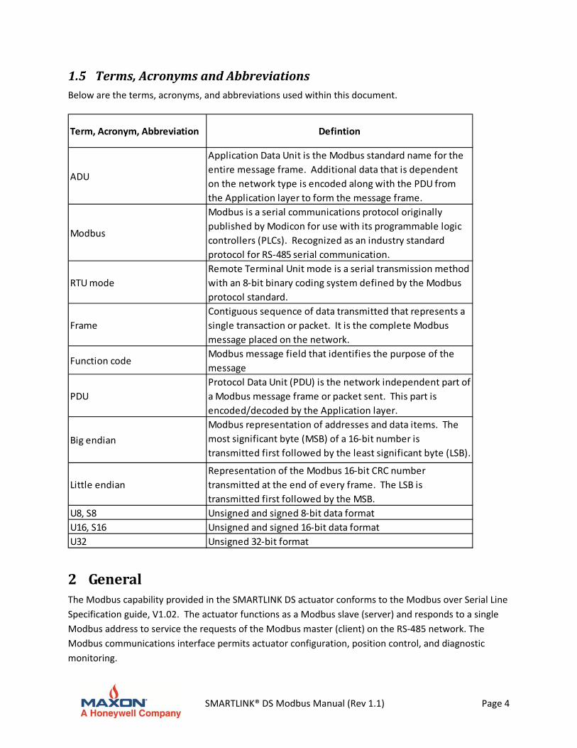
1.5 Terms,AcronymsandAbbreviationsBelow are the terms, acronyms, and abbreviations used within this document.
Term, Acronym, Abbreviation Defintion
ADU
Application Data Unit is the Modbus standard name for the
entire message frame. Additional data that is dependent
on the network type is encoded along with the PDU from
the Application layer to form the message frame.
Modbus
Modbus is a serial communications protocol originally
published by Modicon for use with its programmable logic
controllers (PLCs). Recognized as an industry standard
protocol for RS‐485 serial communication.
RTU mode
Remote Terminal Unit mode is a serial transmission method
with an 8‐bit binary coding system defined by the Modbus
protocol standard.
Frame
Contiguous sequence of data transmitted that represents a
single transaction or packet. It is the complete Modbus
message placed on the network.
Function codeModbus message field that identifies the purpose of the
message
PDU
Protocol Data Unit (PDU) is the network independent part of
a Modbus message frame or packet sent. This part is
encoded/decoded by the Application layer.
Big endian
Modbus representation of addresses and data items. The
most significant byte (MSB) of a 16‐bit number is
transmitted first followed by the least significant byte (LSB).
Little endian
Representation of the Modbus 16‐bit CRC number
transmitted at the end of every frame. The LSB is
transmitted first followed by the MSB.
U8, S8 Unsigned and signed 8‐bit data format
U16, S16 Unsigned and signed 16‐bit data format
U32 Unsigned 32‐bit format
2 GeneralThe Modbus capability provided in the SMARTLINK DS actuator conforms to the Modbus over Serial Line
Specification guide, V1.02. The actuator functions as a Modbus slave (server) and responds to a single
Modbus address to service the requests of the Modbus master (client) on the RS‐485 network. The
Modbus communications interface permits actuator configuration, position control, and diagnostic
monitoring.
SMARTLINK® DS Modbus Manual (Rev 1.1) Page 5
3 PhysicalInterface
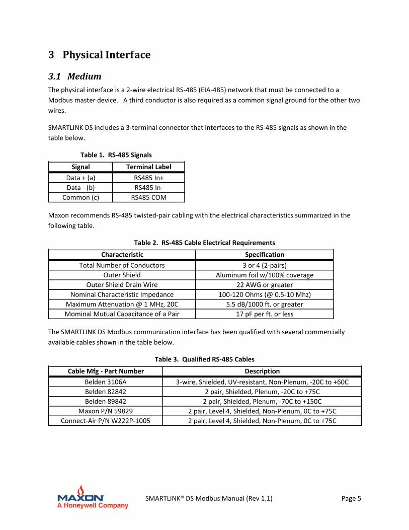
3.1 MediumThe physical interface is a 2‐wire electrical RS‐485 (EIA‐485) network that must be connected to a
Modbus master device. A third conductor is also required as a common signal ground for the other two
wires.
SMARTLINK DS includes a 3‐terminal connector that interfaces to the RS‐485 signals as shown in the
table below.
Table 1. RS‐485 Signals
Signal Terminal Label
Data + (a) RS485 In+
Data ‐ (b) RS485 In‐
Common (c) RS485 COM
Maxon recommends RS‐485 twisted‐pair cabling with the electrical characteristics summarized in the
following table.
Table 2. RS‐485 Cable Electrical Requirements
Characteristic Specification
Total Number of Conductors 3 or 4 (2‐pairs)
Outer Shield Aluminum foil w/100% coverage
Outer Shield Drain Wire 22 AWG or greater
Nominal Characteristic Impedance 100‐120 Ohms (@ 0.5‐10 Mhz)
Maximum Attenuation @ 1 MHz, 20C 5.5 dB/1000 ft. or greater
Mominal Mutual Capacitance of a Pair 17 pF per ft. or less
The SMARTLINK DS Modbus communication interface has been qualified with several commercially
available cables shown in the table below.
Table 3. Qualified RS‐485 Cables
Cable Mfg ‐ Part Number Description
Belden 3106A 3‐wire, Shielded, UV‐resistant, Non‐Plenum, ‐20C to +60C
Belden 82842 2 pair, Shielded, Plenum, ‐20C to +75C
Belden 89842 2 pair, Shielded, Plenum, ‐70C to +150C
Maxon P/N 59829 2 pair, Level 4, Shielded, Non‐Plenum, 0C to +75C
Connect‐Air P/N W222P‐1005 2 pair, Level 4, Shielded, Non‐Plenum, 0C to +75C
SMARTLINK® DS Modbus Manual (Rev 1.1) Page 6
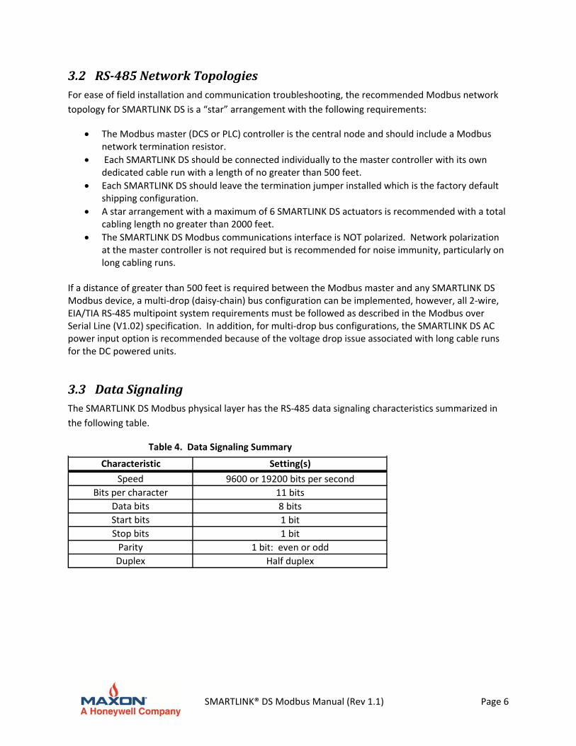
3.2 RS‐485NetworkTopologiesFor ease of field installation and communication troubleshooting, the recommended Modbus network
topology for SMARTLINK DS is a “star” arrangement with the following requirements:
The Modbus master (DCS or PLC) controller is the central node and should include a Modbus network termination resistor.
Each SMARTLINK DS should be connected individually to the master controller with its own dedicated cable run with a length of no greater than 500 feet.
Each SMARTLINK DS should leave the termination jumper installed which is the factory default shipping configuration.
A star arrangement with a maximum of 6 SMARTLINK DS actuators is recommended with a total cabling length no greater than 2000 feet.
The SMARTLINK DS Modbus communications interface is NOT polarized. Network polarization at the master controller is not required but is recommended for noise immunity, particularly on long cabling runs.
If a distance of greater than 500 feet is required between the Modbus master and any SMARTLINK DS Modbus device, a multi‐drop (daisy‐chain) bus configuration can be implemented, however, all 2‐wire, EIA/TIA RS‐485 multipoint system requirements must be followed as described in the Modbus over Serial Line (V1.02) specification. In addition, for multi‐drop bus configurations, the SMARTLINK DS AC power input option is recommended because of the voltage drop issue associated with long cable runs for the DC powered units.
3.3 DataSignalingThe SMARTLINK DS Modbus physical layer has the RS‐485 data signaling characteristics summarized in
the following table.
Table 4. Data Signaling Summary
Characteristic Setting(s)
Speed 9600 or 19200 bits per second
Bits per character 11 bits
Data bits 8 bits
Start bits 1 bit
Stop bits 1 bit
Parity 1 bit: even or odd
Duplex Half duplex
SMARTLINK® DS Modbus Manual (Rev 1.1) Page 7
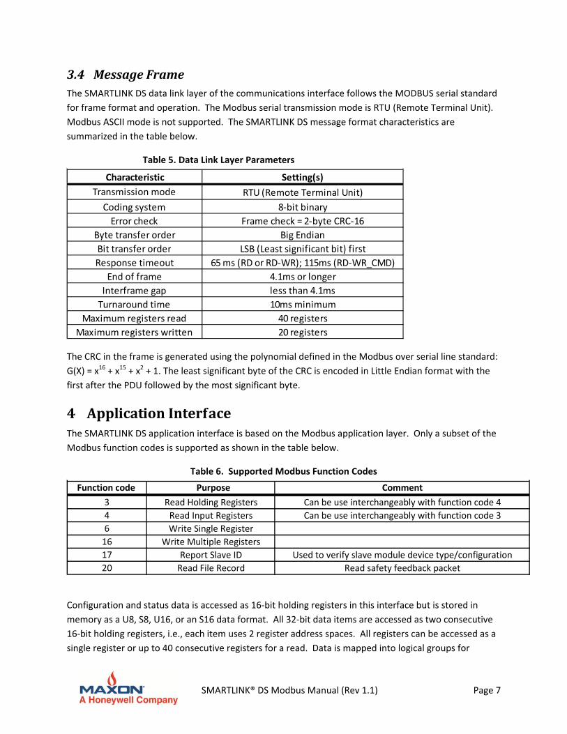
3.4 MessageFrameThe SMARTLINK DS data link layer of the communications interface follows the MODBUS serial standard
for frame format and operation. The Modbus serial transmission mode is RTU (Remote Terminal Unit).
Modbus ASCII mode is not supported. The SMARTLINK DS message format characteristics are
summarized in the table below.
Table 5. Data Link Layer Parameters
Characteristic Setting(s)
Transmission mode RTU (Remote Terminal Unit)
Coding system 8‐bit binary
Error check Frame check = 2‐byte CRC‐16
Byte transfer order Big Endian
Bit transfer order LSB (Least significant bit) first
Response timeout 65 ms (RD or RD‐WR); 115ms (RD‐WR_CMD)
End of frame 4.1ms or longer
Interframe gap less than 4.1ms
Turnaround time 10ms minimum
Maximum registers read 40 registers
Maximum registers written 20 registers
The CRC in the frame is generated using the polynomial defined in the Modbus over serial line standard:
G(X) = x16 + x15 + x2 + 1. The least significant byte of the CRC is encoded in Little Endian format with the
first after the PDU followed by the most significant byte.
4 ApplicationInterfaceThe SMARTLINK DS application interface is based on the Modbus application layer. Only a subset of the
Modbus function codes is supported as shown in the table below.
Table 6. Supported Modbus Function Codes
Function code Purpose Comment
3 Read Holding Registers Can be use interchangeably with function code 4
4 Read Input Registers Can be use interchangeably with function code 3
6 Write Single Register
16 Write Multiple Registers
17 Report Slave ID Used to verify slave module device type/configuration
20 Read File Record Read safety feedback packet
Configuration and status data is accessed as 16‐bit holding registers in this interface but is stored in
memory as a U8, S8, U16, or an S16 data format. All 32‐bit data items are accessed as two consecutive
16‐bit holding registers, i.e., each item uses 2 register address spaces. All registers can be accessed as a
single register or up to 40 consecutive registers for a read. Data is mapped into logical groups for
SMARTLINK® DS Modbus Manual (Rev 1.1) Page 8
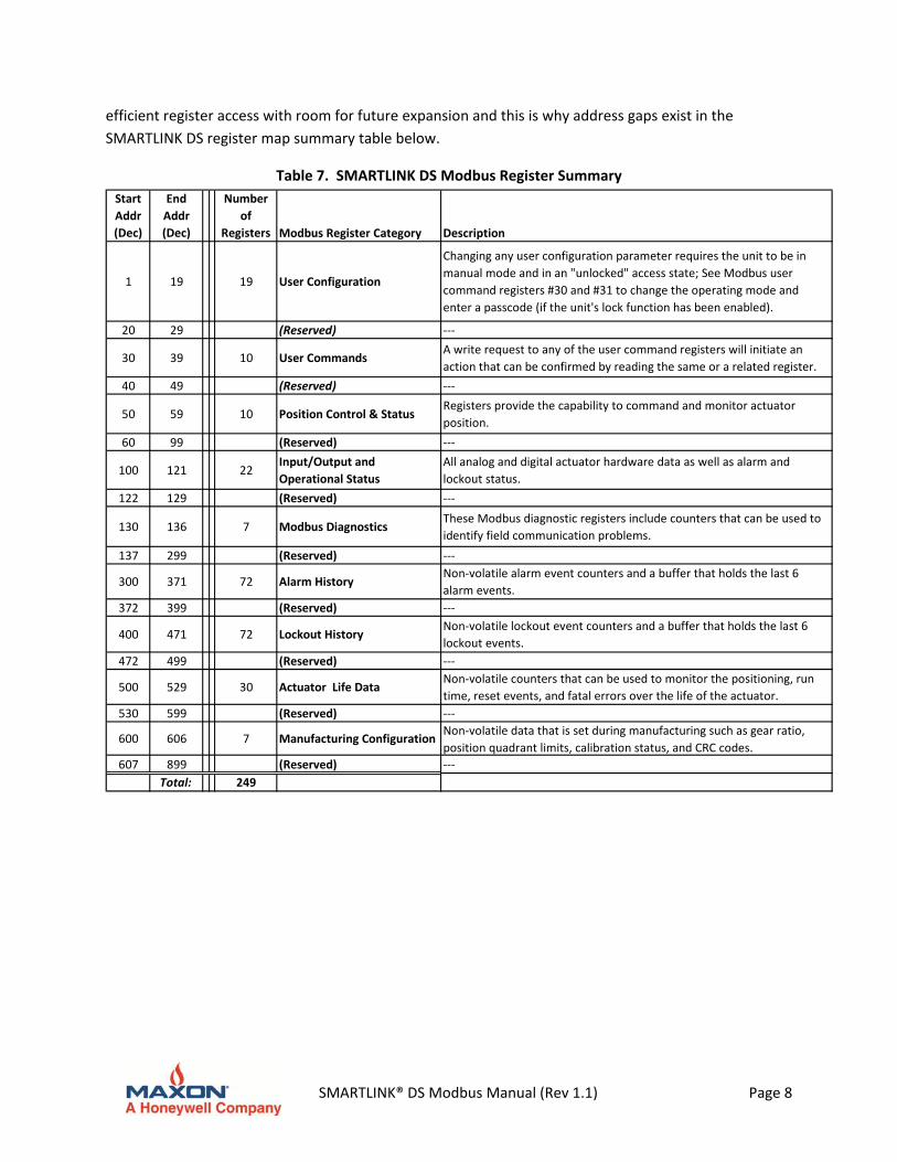
efficient register access with room for future expansion and this is why address gaps exist in the
SMARTLINK DS register map summary table below.
Table 7. SMARTLINK DS Modbus Register Summary
Start
Addr
(Dec)
End
Addr
(Dec)
Number
of
Registers Modbus Register Category Description
1 19 19 User Configuration
Changing any user configuration parameter requires the unit to be in
manual mode and in an "unlocked" access state; See Modbus user
command registers #30 and #31 to change the operating mode and
enter a passcode (if the unit's lock function has been enabled).
20 29 (Reserved) ‐‐‐
30 39 10 User CommandsA write request to any of the user command registers will initiate an
action that can be confirmed by reading the same or a related register.
40 49 (Reserved) ‐‐‐
50 59 10 Position Control & StatusRegisters provide the capability to command and monitor actuator
position.
60 99 (Reserved) ‐‐‐
100 121 22Input/Output and
Operational Status
All analog and digital actuator hardware data as well as alarm and
lockout status.
122 129 (Reserved) ‐‐‐
130 136 7 Modbus DiagnosticsThese Modbus diagnostic registers include counters that can be used to
identify field communication problems.
137 299 (Reserved) ‐‐‐
300 371 72 Alarm HistoryNon‐volatile alarm event counters and a buffer that holds the last 6
alarm events.
372 399 (Reserved) ‐‐‐
400 471 72 Lockout HistoryNon‐volatile lockout event counters and a buffer that holds the last 6
lockout events.
472 499 (Reserved) ‐‐‐
500 529 30 Actuator Life Data Non‐volatile counters that can be used to monitor the positioning, run
time, reset events, and fatal errors over the life of the actuator.
530 599 (Reserved) ‐‐‐
600 606 7 Manufacturing ConfigurationNon‐volatile data that is set during manufacturing such as gear ratio,
position quadrant limits, calibration status, and CRC codes.
607 899 (Reserved) ‐‐‐
Total: 249
SMARTLINK® DS Modbus Manual (Rev 1.1) Page 9
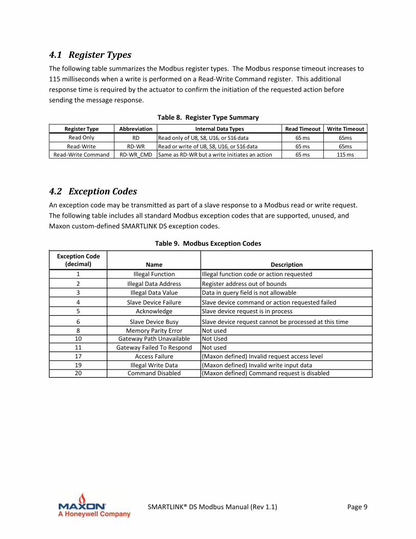
4.1 RegisterTypesThe following table summarizes the Modbus register types. The Modbus response timeout increases to
115 milliseconds when a write is performed on a Read‐Write Command register. This additional
response time is required by the actuator to confirm the initiation of the requested action before
sending the message response.
Table 8. Register Type Summary
Register Type Abbreviation Internal Data Types Read Timeout Write Timeout
Read Only RD Read only of U8, S8, U16, or S16 data 65 ms 65ms
Read‐Write RD‐WR Read or write of U8, S8, U16, or S16 data 65 ms 65ms
Read‐Write Command RD‐WR_CMD Same as RD‐WR but a write initiates an action 65 ms 115 ms
4.2 ExceptionCodesAn exception code may be transmitted as part of a slave response to a Modbus read or write request.
The following table includes all standard Modbus exception codes that are supported, unused, and
Maxon custom‐defined SMARTLINK DS exception codes.
Table 9. Modbus Exception Codes
Exception Code(decimal) Name Description
1 Illegal Function Illegal function code or action requested
2 Illegal Data Address Register address out of bounds
3 Illegal Data Value Data in query field is not allowable
4 Slave Device Failure Slave device command or action requested failed
5 Acknowledge Slave device request is in process
6 Slave Device Busy Slave device request cannot be processed at this time
8 Memory Parity Error Not used10 Gateway Path Unavailable Not Used
11 Gateway Failed To Respond Not used
17 Access Failure (Maxon defined) Invalid request access level
19 Illegal Write Data (Maxon defined) Invalid write input data20 Command Disabled (Maxon defined) Command request is disabled
SMARTLINK® DS Modbus Manual (Rev 1.1) Page 10
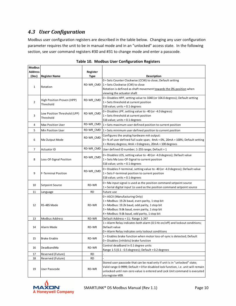
4.3 UserConfigurationModbus user configuration registers are described in the table below. Changing any user configuration
parameter requires the unit to be in manual mode and in an "unlocked" access state. In the following
section, see user command registers #30 and #31 to change mode and enter a passcode.
Table 10. Modbus User Configuration Registers
Modbus
Address
(Dec) Register Name
Register
Type Description
1 Rotation RD‐WR_CMD
0 = Sets Counter Clockwise (CCW) to close; Default setting
1 = Sets Clockwise (CW) to close
Rotation is defined as shaft movement towards the 0% position when
viewing the actuator shaft
2High Position Proven (HPP)
Threshold
RD‐WR_CMD0 = Disables HPP, setting value to 1040 (or 104.0 degress); Default setting
1 = Sets threshold at current position
S16 value; units = 0.1 degrees
3Low Position Threshold (LPP)
Threshold
RD‐WR_CMD0 = Disables LPP, setting value to ‐40 (or ‐4.0 degress)
1 = Sets threshold at current position
S16 value; units = 0.1 degrees
4 Max Position User RD‐WR_CMD 1 = Sets maximum user defined position to current position
5 Min Position User RD‐WR_CMD 1 = Sets minimum user defined position to current position
6 Ma Output ModeRD‐WR_CMD
Configures the analog hardware mA output:
0 = % of user defined full scale span; 4mA = 0%, 20mA = 100%; Default setting
1 = Rotary degress; 4mA = 0 degrees, 20mA = 100 degrees
7 Actuator ID RD‐WR_CMD User defined ID number; 1‐255 range; Default = 1
8 Loss‐Of‐Signal PositionRD‐WR_CMD
0 = Disables LOS, setting value to ‐40 (or ‐4.0 degress); Default value
1 = Sets Ma Loss‐Of‐Signal to current position
S16 value; units = 0.1 degrees
9 F‐Terminal PositionRD‐WR_CMD
0 = Disables F‐terminal, setting value to ‐40 (or ‐4.0 degress); Default value
1 = Sets F‐terminal position to current position
S16 value; units = 0.1 degrees
10 Setpoint Source RD‐WR0 = Ma input signal is used as the position command setpoint source
1 = Serial digital input \is used as the position command setpoint source
11 Language RD Future use
12 RS‐485 Mode RD‐WR
0 = ASCII (Manufacturing Only)
1 = Modbus: 19.2k baud, even parity, 1 stop bit
2 = Modbus: 19.2k baud, odd parity, 1 stop bit
3 = Modbus: 9.6k baud, even parity, 1 stop bit
4 = Modbus: 9.6k baud, odd parity, 1 stop bit
13 Modbus Address RD‐WR Default Address = 11; Range 1‐247
14 Alarm Mode RD‐WR
1 = Alarm Relay indicates both alarm (0.5 Hz on/off) and lockout conditions;
Default value
0 = Alarm Relay indicates only lockout conditions
15 Brake Enable RD‐WR1 = Enables brake function when motor loss‐of‐sync is detected; Default
0 = Disables (inhibits) brake function
16 DeadbandMa RD‐WRControl deadband in 0.1 degree units
Range 1‐5 (0.1 ‐ 0.5 degrees); Default = 0.2 degrees
17 Reserved (Future) RD ‐
18 Reserved (Future) RD ‐
19 User Passcode RD‐WR
Stored user passcode that can be read only if unit is in "unlocked" state;
Valid range 0‐9999; Default = 0 for disabled lock function, i.e. unit will remain
unlocked until non‐zero value is entered and Lock Unit command is executed
via register #39.
SMARTLINK® DS Modbus Manual (Rev 1.1) Page 11
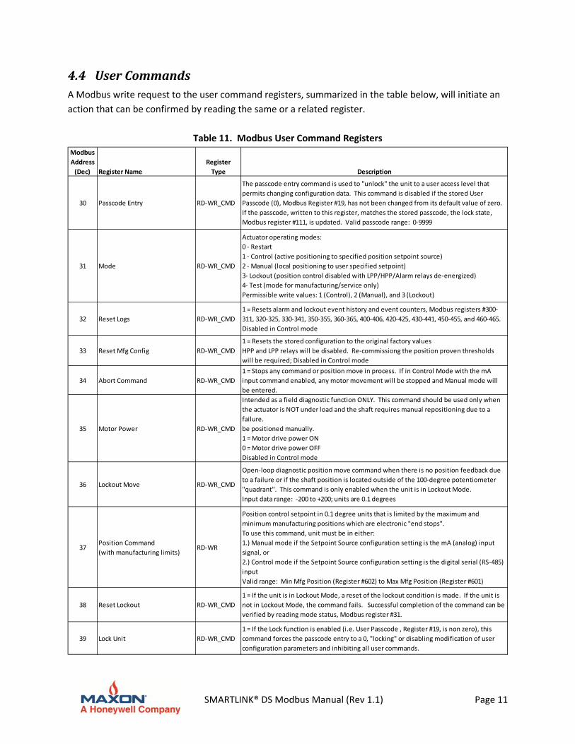
4.4 UserCommandsA Modbus write request to the user command registers, summarized in the table below, will initiate an
action that can be confirmed by reading the same or a related register.
Table 11. Modbus User Command Registers
Modbus
Address
(Dec) Register Name
Register
Type Description
30 Passcode Entry RD‐WR_CMD
The passcode entry command is used to "unlock" the unit to a user access level that
permits changing configuration data. This command is disabled if the stored User
Passcode (0), Modbus Register #19, has not been changed from its default value of zero.
If the passcode, written to this register, matches the stored passcode, the lock state,
Modbus register #111, is updated. Valid passcode range: 0‐9999
31 Mode RD‐WR_CMD
Actuator operating modes:
0 ‐ Restart
1 ‐ Control (active positioning to specified position setpoint source)
2 ‐ Manual (local positioning to user specified setpoint)
3‐ Lockout (position control disabled with LPP/HPP/Alarm relays de‐energized)
4‐ Test (mode for manufacturing/service only)
Permissible write values: 1 (Control), 2 (Manual), and 3 (Lockout)
32 Reset Logs RD‐WR_CMD
1 = Resets alarm and lockout event history and event counters, Modbus registers #300‐
311, 320‐325, 330‐341, 350‐355, 360‐365, 400‐406, 420‐425, 430‐441, 450‐455, and 460‐465.
Disabled in Control mode
33 Reset Mfg Config RD‐WR_CMD
1 = Resets the stored configuration to the original factory values
HPP and LPP relays will be disabled. Re‐commissiong the position proven thresholds
will be required; Disabled in Control mode
34 Abort Command RD‐WR_CMD
1 = Stops any command or position move in process. If in Control Mode with the mA
input command enabled, any motor movement will be stopped and Manual mode will
be entered.
35 Motor Power RD‐WR_CMD
Intended as a field diagnostic function ONLY. This command should be used only when
the actuator is NOT under load and the shaft requires manual repositioning due to a
failure.
be positioned manually.
1 = Motor drive power ON
0 = Motor drive power OFF
Disabled in Control mode
36 Lockout Move RD‐WR_CMD
Open‐loop diagnostic position move command when there is no position feedback due
to a failure or if the shaft position is located outside of the 100‐degree potentiometer
"quadrant". This command is only enabled when the unit is in Lockout Mode.
Input data range: ‐200 to +200; units are 0.1 degrees
37Position Command
(with manufacturing limits)RD‐WR
Position control setpoint in 0.1 degree units that is limited by the maximum and
minimum manufacturing positions which are electronic "end stops".
To use this command, unit must be in either:
1.) Manual mode if the Setpoint Source configuration setting is the mA (analog) input
signal, or
2.) Control mode if the Setpoint Source configuration setting is the digital serial (RS‐485)
input
Valid range: Min Mfg Position (Register #602) to Max Mfg Position (Register #601)
38 Reset Lockout RD‐WR_CMD
1 = If the unit is in Lockout Mode, a reset of the lockout condition is made. If the unit is
not in Lockout Mode, the command fails. Successful completion of the command can be
verified by reading mode status, Modbus register #31.
39 Lock Unit RD‐WR_CMD
1 = If the Lock function is enabled (i.e. User Passcode , Register #19, is non zero), this
command forces the passcode entry to a 0, "locking" or disabling modification of user
configuration parameters and inhibiting all user commands.
SMARTLINK® DS Modbus Manual (Rev 1.1) Page 12
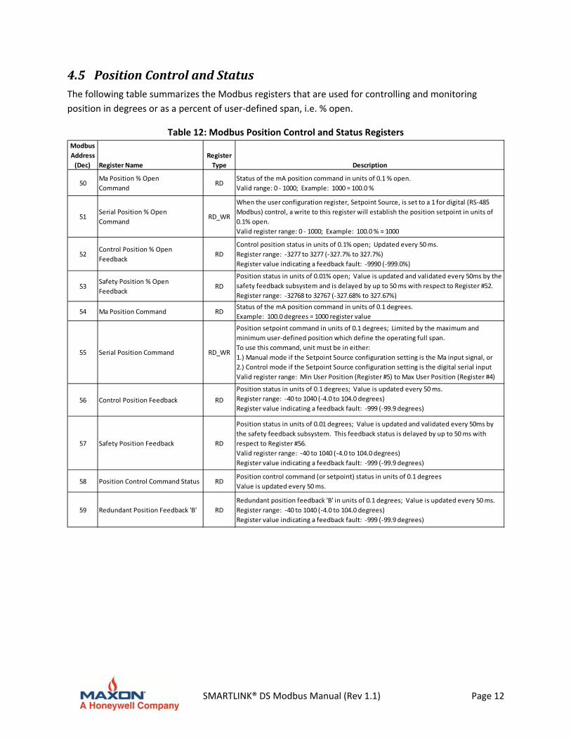
4.5 PositionControlandStatusThe following table summarizes the Modbus registers that are used for controlling and monitoring
position in degrees or as a percent of user‐defined span, i.e. % open.
Table 12: Modbus Position Control and Status Registers Modbus
Address
(Dec) Register Name
Register
Type Description
50Ma Position % Open
CommandRD
Status of the mA position command in units of 0.1 % open.
Valid range: 0 ‐ 1000; Example: 1000 = 100.0 %
51Serial Position % Open
CommandRD_WR
When the user configuration register, Setpoint Source, is set to a 1 for digital (RS‐485
Modbus) control, a write to this register will establish the position setpoint in units of
0.1% open.
Valid register range: 0 ‐ 1000; Example: 100.0 % = 1000
52Control Position % Open
FeedbackRD
Control position status in units of 0.1% open; Updated every 50 ms.
Register range: ‐3277 to 3277 (‐327.7% to 327.7%)
Register value indicating a feedback fault: ‐9990 (‐999.0%)
53Safety Position % Open
Feedback RD
Position status in units of 0.01% open; Value is updated and validated every 50ms by the
safety feedback subsystem and is delayed by up to 50 ms with respect to Register #52.
Register range: ‐32768 to 32767 (‐327.68% to 327.67%)
54 Ma Position Command RDStatus of the mA position command in units of 0.1 degrees.
Example: 100.0 degrees = 1000 register value
55 Serial Position Command RD_WR
Position setpoint command in units of 0.1 degrees; Limited by the maximum and
minimum user‐defined position which define the operating full span.
To use this command, unit must be in either:
1.) Manual mode if the Setpoint Source configuration setting is the Ma input signal, or
2.) Control mode if the Setpoint Source configuration setting is the digital serial input
Valid register range: Min User Position (Register #5) to Max User Position (Register #4)
56 Control Position Feedback RD
Position status in units of 0.1 degrees; Value is updated every 50 ms.
Register range: ‐40 to 1040 (‐4.0 to 104.0 degrees)
Register value indicating a feedback fault: ‐999 (‐99.9 degrees)
57 Safety Position Feedback RD
Position status in units of 0.01 degrees; Value is updated and validated every 50ms by
the safety feedback subsystem. This feedback status is delayed by up to 50 ms with
respect to Register #56.
Valid register range: ‐40 to 1040 (‐4.0 to 104.0 degrees)
Register value indicating a feedback fault: ‐999 (‐99.9 degrees)
58 Position Control Command Status RDPosition control command (or setpoint) status in units of 0.1 degrees
Value is updated every 50 ms.
59 Redundant Position Feedback 'B' RD
Redundant position feedback 'B' in units of 0.1 degrees; Value is updated every 50 ms.
Register range: ‐40 to 1040 (‐4.0 to 104.0 degrees)
Register value indicating a feedback fault: ‐999 (‐99.9 degrees)
SMARTLINK® DS Modbus Manual (Rev 1.1) Page 13
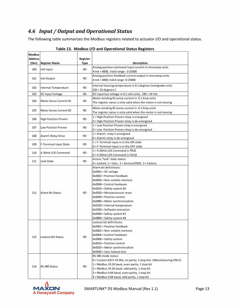
4.6 Input/OutputandOperationalStatusThe following table summarizes the Modbus registers related to actuator I/O and operational status.
Table 13. Modbus I/O and Operational Status Registers
Modbus
Address
(Dec) Register Name
Register
Type Description
100 mA Input RDAnalog position command input current in microamp units
4 mA = 4000; Valid range: 0‐25000
101 mA Output RDAnalog position feedback current output in microamp units
4 mA = 4000; Valid range: 0‐25000
102 Internal Temperature RDInternal housing temperature in 0.1 degrees Centigrade units
250 = 25 degrees C
103 DC Input Voltage RD DC input bus voltage in 0.1 volt units; 240 = 24 Vdc
104 Motor Sense Current #1 RDMotor winding #1 sense current in 0.1 Amp units
The register value is only valid when the motor is not moving
105 Motor Sense Current #2 RDMotor winding #2 sense current in 0.1 Amp units
The register value is only valid when the motor is not moving
106 High Position Proven RD1 = High Position Proven relay is energized
0 = High Position Proven relay is de‐energized
107 Low Position Proven RD1 = Low Position Proven relay is energized
0 = Low Position Proven relay is de‐energized
108 Alarm\ Relay Drive RD1 = Alarm\ relay is energized
0 = Alarm\ relay is de‐energized
109 F‐Terminal Input State RD1 = F‐Terminal input is in the ON state
0 = F‐Terminal input is in the OFF state
110 4‐20mA LOS Command RD1 = 4‐20mA LOS Command is TRUE
0 = 4‐20mA LOS Command is FALSE
111 Lock State RDAccess "lock" state status:
0 = Locked; 1 = User; 2 = Service/OEM; 3 = Factory
112 Alarm Bit Status RD
Alarm bit definitions:
0x0001 = DC voltage
0x0002 = Position feedback
0x0004 = Non‐volatile memory
0x0008 = Control hardware
0x0010 = Safety system #2
0x0020 = Microprocessor reset
0x0040 = Position control
0x0080 = Motor synchronization
0x0100 = Internal temperature
0x0200 = Software execution
0x0400 = Safety system #1
0x0800 = Safety system #3
113 Lockout Bit Status RD
Lockout bit definitions:
0x0001 = Position feedback
0x0002 = Non‐volatile memory
0x0004 = Control hardware
0x0008 = Safety system
0x0010 = Position control
0x0020 = Motor synchronization
0x0040 = User lockout test
114 RS‐485 Status RD
RS‐485 mode status:
0 = Custom ASCII 19.2Kb, no parity, 2 stop bits (Manufacturing ONLY)
1 = Modbus 19.2K baud, even parity, 1 stop bit
2 = Modbus 19.2K baud, odd parity, 1 stop bit
3 = Modbus 9.6K baud, even parity, 1 stop bit
4 = Modbus 9.6K baud, odd parity, 1 stop bit
SMARTLINK® DS Modbus Manual (Rev 1.1) Page 14
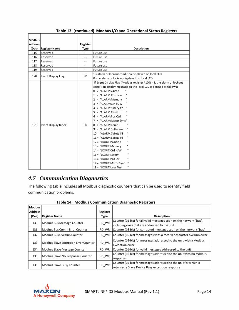
Table 13. (continued) Modbus I/O and Operational Status Registers
Modbus
Address
(Dec) Register Name
Register
Type Description
115 Reserved ‐‐ Future use
116 Reserved ‐‐ Future use
117 Reserved ‐‐ Future use
118 Reserved ‐‐ Future use
119 Reserved ‐‐ Future use
120 Event Display Flag RD1 = alarm or lockout condition displayed on local LCD
0 = no alarm or lockout displayed on local LCD
121 Event Display Index RD
If Event Display Flag (Modbus register #120) = 1, the alarm or lockout
condition display message on the local LCD is defined as follows:
0 = "ALARM:24Vdc "
1 = "ALARM:Position "
2 = "ALARM:Memory "
3 = "ALARM:Ctrl H/W "
4 = "ALARM:Safety #2 "
5 = "ALARM:Reset "
6 = "ALARM:Pos Ctrl "
7 = "ALARM:Motor Sync "
8 = "ALARM:Temp "
9 = "ALARM:Software "
10 = "ALARM:Safety #1 "
11 = "ALARM:Safety #3 "
12 = "LKOUT:Position "
13 = "LKOUT:Memory "
14 = "LKOUT:Ctrl H/W "
15 = "LKOUT:Safety "
16 = "LKOUT:Pos Ctrl "
17 = "LKOUT:Motor Sync "
18 = "LKOUT:User Test "
4.7 CommunicationDiagnosticsThe following table includes all Modbus diagnostic counters that can be used to identify field
communication problems.
Table 14. Modbus Communication Diagnostic Registers Modbus
Address
(Dec) Register Name
Register
Type Description
130 Modbus Bus Message Counter RD_WRCounter (16‐bit) for all valid messages seen on the network "bus",
including ones that are addressed to the unit
131 Modbus Bus Comm Error Counter RD_WR Counter (16‐bit) for corrupted messages seen on the network "bus"
132 Modbus Bus Overrun Counter RD_WR Counter (16‐bit) for messages with a receiver character overrun error
133 Modbus Slave Exception Error Counter RD_WRCounter (16‐bit) for messages addressed to the unit with a Modbus
exception error
134 Modbus Slave Message Counter RD_WR Counter (16‐bit) for valid messages addressed to the unit
135 Modbus Slave No Response Counter RD_WRCounter (16‐bit) for messages addressed to the unit with no Modbus
response
136 Modbus Slave Busy Counter RD_WRCounter (16‐bit) for messages addressed to the unit for which it
returned a Slave Device Busy exception response
SMARTLINK® DS Modbus Manual (Rev 1.1) Page 15
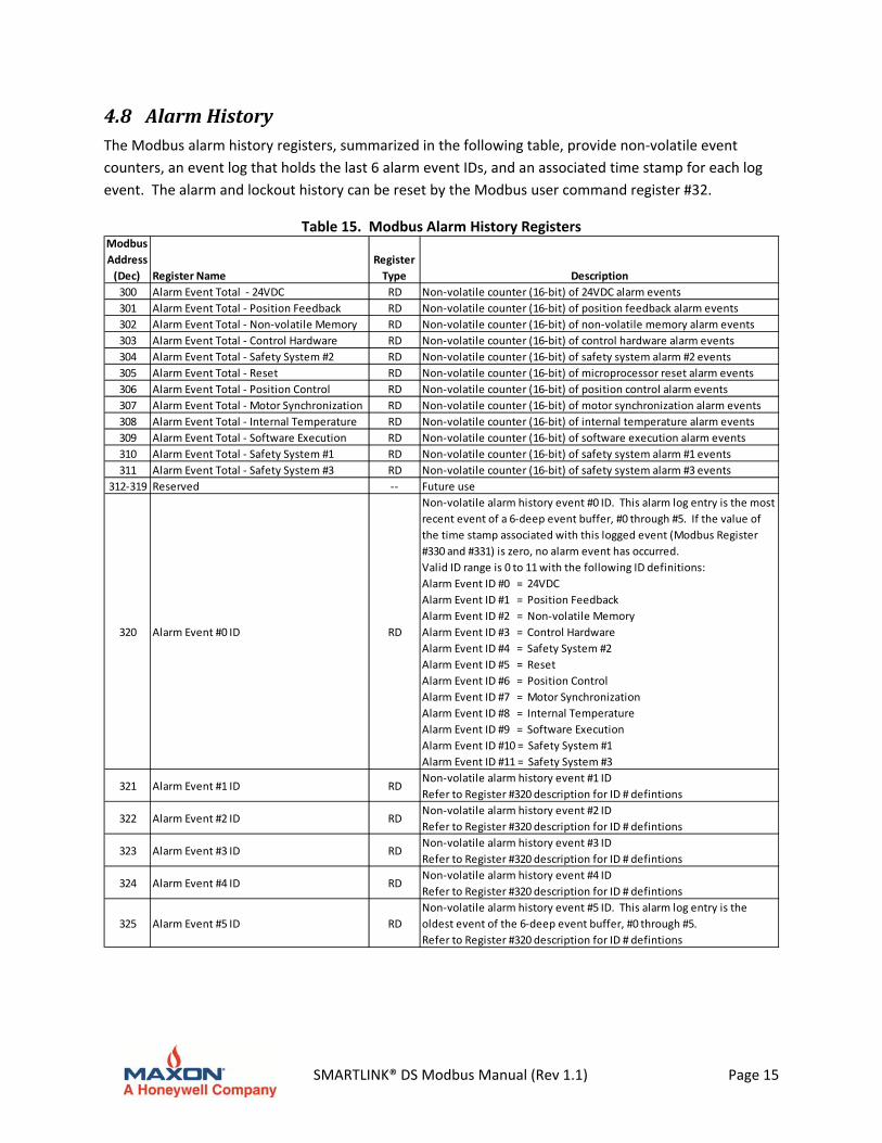
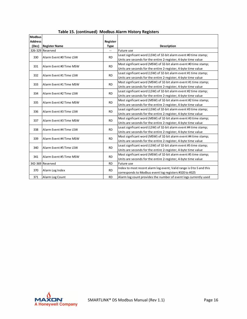
4.8 AlarmHistoryThe Modbus alarm history registers, summarized in the following table, provide non‐volatile event
counters, an event log that holds the last 6 alarm event IDs, and an associated time stamp for each log
event. The alarm and lockout history can be reset by the Modbus user command register #32.
Table 15. Modbus Alarm History Registers Modbus
Address
(Dec) Register Name
Register
Type Description
300 Alarm Event Total ‐ 24VDC RD Non‐volatile counter (16‐bit) of 24VDC alarm events
301 Alarm Event Total ‐ Position Feedback RD Non‐volatile counter (16‐bit) of position feedback alarm events
302 Alarm Event Total ‐ Non‐volatile Memory RD Non‐volatile counter (16‐bit) of non‐volatile memory alarm events
303 Alarm Event Total ‐ Control Hardware RD Non‐volatile counter (16‐bit) of control hardware alarm events
304 Alarm Event Total ‐ Safety System #2 RD Non‐volatile counter (16‐bit) of safety system alarm #2 events
305 Alarm Event Total ‐ Reset RD Non‐volatile counter (16‐bit) of microprocessor reset alarm events
306 Alarm Event Total ‐ Position Control RD Non‐volatile counter (16‐bit) of position control alarm events
307 Alarm Event Total ‐ Motor Synchronization RD Non‐volatile counter (16‐bit) of motor synchronization alarm events
308 Alarm Event Total ‐ Internal Temperature RD Non‐volatile counter (16‐bit) of internal temperature alarm events
309 Alarm Event Total ‐ Software Execution RD Non‐volatile counter (16‐bit) of software execution alarm events
310 Alarm Event Total ‐ Safety System #1 RD Non‐volatile counter (16‐bit) of safety system alarm #1 events
311 Alarm Event Total ‐ Safety System #3 RD Non‐volatile counter (16‐bit) of safety system alarm #3 events
312‐319 Reserved ‐‐ Future use
320 Alarm Event #0 ID RD
Non‐volatile alarm history event #0 ID. This alarm log entry is the most
recent event of a 6‐deep event buffer, #0 through #5. If the value of
the time stamp associated with this logged event (Modbus Register
#330 and #331) is zero, no alarm event has occurred.
Valid ID range is 0 to 11 with the following ID definitions:
Alarm Event ID #0 = 24VDC
Alarm Event ID #1 = Position Feedback
Alarm Event ID #2 = Non‐volatile Memory
Alarm Event ID #3 = Control Hardware
Alarm Event ID #4 = Safety System #2
Alarm Event ID #5 = Reset
Alarm Event ID #6 = Position Control
Alarm Event ID #7 = Motor Synchronization
Alarm Event ID #8 = Internal Temperature
Alarm Event ID #9 = Software Execution
Alarm Event ID #10 = Safety System #1
Alarm Event ID #11 = Safety System #3
321 Alarm Event #1 ID RDNon‐volatile alarm history event #1 ID
Refer to Register #320 description for ID # defintions
322 Alarm Event #2 ID RDNon‐volatile alarm history event #2 ID
Refer to Register #320 description for ID # defintions
323 Alarm Event #3 ID RDNon‐volatile alarm history event #3 ID
Refer to Register #320 description for ID # defintions
324 Alarm Event #4 ID RDNon‐volatile alarm history event #4 ID
Refer to Register #320 description for ID # defintions
325 Alarm Event #5 ID RD
Non‐volatile alarm history event #5 ID. This alarm log entry is the
oldest event of the 6‐deep event buffer, #0 through #5.
Refer to Register #320 description for ID # defintions
SMARTLINK® DS Modbus Manual (Rev 1.1) Page 16
Table 15. (continued) Modbus Alarm History Registers Modbus
Address
(Dec) Register Name
Register
Type Description
326‐329 Reserved ‐‐ Future use
330 Alarm Event #0 Time LSW RDLeast signficant word (LSW) of 32‐bit alarm event #0 time stamp;
Units are seconds for the entire 2‐register, 4‐byte time value
331 Alarm Event #0 Time MSW RDMost signficant word (MSW) of 32‐bit alarm event #0 time stamp;
Units are seconds for the entire 2‐register, 4‐byte time value
332 Alarm Event #1 Time LSW RDLeast signficant word (LSW) of 32‐bit alarm event #1 time stamp;
Units are seconds for the entire 2‐register, 4‐byte time value
333 Alarm Event #1 Time MSW RDMost signficant word (MSW) of 32‐bit alarm event #1 time stamp;
Units are seconds for the entire 2‐register, 4‐byte time value
334 Alarm Event #2 Time LSW RDLeast signficant word (LSW) of 32‐bit alarm event #2 time stamp;
Units are seconds for the entire 2‐register, 4‐byte time value
335 Alarm Event #2 Time MSW RDMost signficant word (MSW) of 32‐bit alarm event #2 time stamp;
Units are seconds for the entire 2‐register, 4‐byte time value
336 Alarm Event #3 Time LSW RDLeast signficant word (LSW) of 32‐bit alarm event #3 time stamp;
Units are seconds for the entire 2‐register, 4‐byte time value
337 Alarm Event #3 Time MSW RDMost signficant word (MSW) of 32‐bit alarm event #3 time stamp;
Units are seconds for the entire 2‐register, 4‐byte time value
338 Alarm Event #4 Time LSW RDLeast signficant word (LSW) of 32‐bit alarm event #4 time stamp;
Units are seconds for the entire 2‐register, 4‐byte time value
339 Alarm Event #4 Time MSW RDMost signficant word (MSW) of 32‐bit alarm event #4 time stamp;
Units are seconds for the entire 2‐register, 4‐byte time value
340 Alarm Event #5 Time LSW RDLeast signficant word (LSW) of 32‐bit alarm event #5 time stamp;
Units are seconds for the entire 2‐register, 4‐byte time value
341 Alarm Event #5 Time MSW RDMost signficant word (MSW) of 32‐bit alarm event #5 time stamp;
Units are seconds for the entire 2‐register, 4‐byte time value
342‐369 Reserved RD Future use
370 Alarm Log Index RDIndex to most recent alarm log event; Valid range is 0 to 5 and this
corresponds to Modbus event log registers #320 to #325
371 Alarm Log Count RD Alarm log count provides the number of event logs currently used
SMARTLINK® DS Modbus Manual (Rev 1.1) Page 17
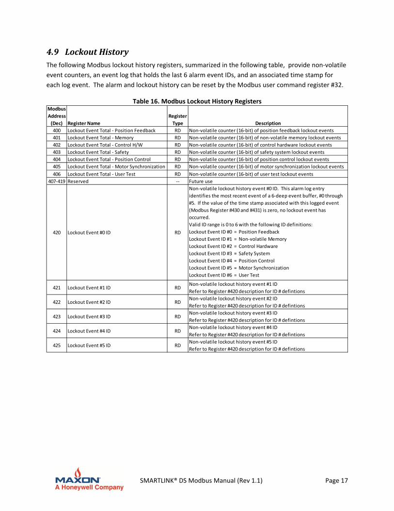
4.9 LockoutHistoryThe following Modbus lockout history registers, summarized in the following table, provide non‐volatile
event counters, an event log that holds the last 6 alarm event IDs, and an associated time stamp for
each log event. The alarm and lockout history can be reset by the Modbus user command register #32.
Table 16. Modbus Lockout History Registers Modbus
Address
(Dec) Register Name
Register
Type Description
400 Lockout Event Total ‐ Position Feedback RD Non‐volatile counter (16‐bit) of position feedback lockout events
401 Lockout Event Total ‐ Memory RD Non‐volatile counter (16‐bit) of non‐volatile memory lockout events
402 Lockout Event Total ‐ Control H/W RD Non‐volatile counter (16‐bit) of control hardware lockout events
403 Lockout Event Total ‐ Safety RD Non‐volatile counter (16‐bit) of safety system lockout events
404 Lockout Event Total ‐ Position Control RD Non‐volatile counter (16‐bit) of position control lockout events
405 Lockout Event Total ‐ Motor Synchronization RD Non‐volatile counter (16‐bit) of motor synchronization lockout events
406 Lockout Event Total ‐ User Test RD Non‐volatile counter (16‐bit) of user test lockout events
407‐419 Reserved ‐‐ Future use
420 Lockout Event #0 ID RD
Non‐volatile lockout history event #0 ID. This alarm log entry
identifies the most recent event of a 6‐deep event buffer, #0 through
#5. If the value of the time stamp associated with this logged event
(Modbus Register #430 and #431) is zero, no lockout event has
occurred.
Valid ID range is 0 to 6 with the following ID definitions:
Lockout Event ID #0 = Position Feedback
Lockout Event ID #1 = Non‐volatile Memory
Lockout Event ID #2 = Control Hardware
Lockout Event ID #3 = Safety System
Lockout Event ID #4 = Position Control
Lockout Event ID #5 = Motor Synchronization
Lockout Event ID #6 = User Test
421 Lockout Event #1 ID RDNon‐volatile lockout history event #1 ID
Refer to Register #420 description for ID # defintions
422 Lockout Event #2 ID RDNon‐volatile lockout history event #2 ID
Refer to Register #420 description for ID # defintions
423 Lockout Event #3 ID RDNon‐volatile lockout history event #3 ID
Refer to Register #420 description for ID # defintions
424 Lockout Event #4 ID RDNon‐volatile lockout history event #4 ID
Refer to Register #420 description for ID # defintions
425 Lockout Event #5 ID RDNon‐volatile lockout history event #5 ID
Refer to Register #420 description for ID # defintions

SMARTLINK® DS Modbus Manual (Rev 1.1) Page 18
Table 16. (continued) Modbus Lockout History Registers
Modbus
Address
(Dec) Register Name
Register
Type Description
426‐429 Reserved ‐‐ Future use
430 Lockout Event #0 Time LSW RDLeast signficant word (LSW) of 32‐bit lockout event #0 time stamp;
Units are seconds for the entire 2‐register, 4‐byte time value
431 Lockout Event #0 Time MSW RDMost signficant word (MSW) of 32‐bit lockout event #0 time stamp;
Units are seconds for the entire 2‐register, 4‐byte time value
432 Lockout Event #1 Time LSW RDLeast signficant word (LSW) of 32‐bit lockout event #1 time stamp;
Units are seconds for the entire 2‐register, 4‐byte time value
433 Lockout Event #1 Time MSW RDMost signficant word (MSW) of 32‐bit lockout event #1 time stamp;
Units are seconds for the entire 2‐register, 4‐byte time value
434 Lockout Event #2 Time LSW RDLeast signficant word (LSW) of 32‐bit lockout event #2 time stamp;
Units are seconds for the entire 2‐register, 4‐byte time value
435 Lockout Event #2 Time MSW RDMost signficant word (MSW) of 32‐bit lockout event #2 time stamp;
Units are seconds for the entire 2‐register, 4‐byte time value
436 Lockout Event #3 Time LSW RDLeast signficant word (LSW) of 32‐bit lockout event #3 time stamp;
Units are seconds for the entire 2‐register, 4‐byte time value
437 Lockout Event #3 Time MSW RDMost signficant word (MSW) of 32‐bit lockout event #3 time stamp;
Units are seconds for the entire 2‐register, 4‐byte time value
438 Lockout Event #4 Time LSW RDLeast signficant word (LSW) of 32‐bit lockout event #4 time stamp;
Units are seconds for the entire 2‐register, 4‐byte time value
439 Lockout Event #4 Time MSW RDMost signficant word (MSW) of 32‐bit lockout event #4 time stamp;
Units are seconds for the entire 2‐register, 4‐byte time value
440 Lockout Event #5 Time LSW RDLeast signficant word (LSW) of 32‐bit lockout event #5 time stamp;
Units are seconds for the entire 2‐register, 4‐byte time value
441 Lockout Event #5 Time MSW RDMost signficant word (MSW) of 32‐bit lockout event #5 time stamp;
Units are seconds for the entire 2‐register, 4‐byte time value
442‐469 Reserved ‐‐ Future use
470 Lockout Log Index RDIndex to most recent lockout log event; Valid range is 0 to 5 and this
corresponds to Modbus event log registers #420 to #425
471 Lockout Log Count RD Lockout log count provides the number of event logs currently used
SMARTLINK® DS Modbus Manual (Rev 1.1) Page 19
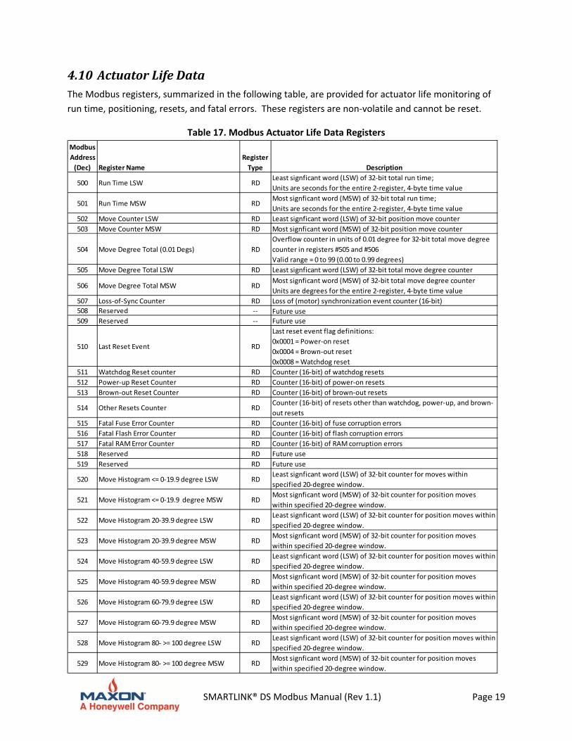
4.10 ActuatorLifeDataThe Modbus registers, summarized in the following table, are provided for actuator life monitoring of
run time, positioning, resets, and fatal errors. These registers are non‐volatile and cannot be reset.
Table 17. Modbus Actuator Life Data Registers
Modbus
Address
(Dec) Register Name
Register
Type Description
500 Run Time LSW RDLeast signficant word (LSW) of 32‐bit total run time;
Units are seconds for the entire 2‐register, 4‐byte time value
501 Run Time MSW RDMost signficant word (MSW) of 32‐bit total run time;
Units are seconds for the entire 2‐register, 4‐byte time value
502 Move Counter LSW RD Least signficant word (LSW) of 32‐bit position move counter
503 Move Counter MSW RD Most signficant word (MSW) of 32‐bit position move counter
504 Move Degree Total (0.01 Degs) RD
Overflow counter in units of 0.01 degree for 32‐bit total move degree
counter in registers #505 and #506
Valid range = 0 to 99 (0.00 to 0.99 degrees)
505 Move Degree Total LSW RD Least signficant word (LSW) of 32‐bit total move degree counter
506 Move Degree Total MSW RDMost signficant word (MSW) of 32‐bit total move degree counter
Units are degrees for the entire 2‐register, 4‐byte time value
507 Loss‐of‐Sync Counter RD Loss of (motor) synchronization event counter (16‐bit)
508 Reserved ‐‐ Future use
509 Reserved ‐‐ Future use
510 Last Reset Event RD
Last reset event flag definitions:
0x0001 = Power‐on reset
0x0004 = Brown‐out reset
0x0008 = Watchdog reset
511 Watchdog Reset counter RD Counter (16‐bit) of watchdog resets
512 Power‐up Reset Counter RD Counter (16‐bit) of power‐on resets
513 Brown‐out Reset Counter RD Counter (16‐bit) of brown‐out resets
514 Other Resets Counter RDCounter (16‐bit) of resets other than watchdog, power‐up, and brown‐
out resets
515 Fatal Fuse Error Counter RD Counter (16‐bit) of fuse corruption errors
516 Fatal Flash Error Counter RD Counter (16‐bit) of flash corruption errors
517 Fatal RAM Error Counter RD Counter (16‐bit) of RAM corruption errors
518 Reserved RD Future use
519 Reserved RD Future use
520 Move Histogram <= 0‐19.9 degree LSW RDLeast signficant word (LSW) of 32‐bit counter for moves within
specified 20‐degree window.
521 Move Histogram <= 0‐19.9 degree MSW RDMost signficant word (MSW) of 32‐bit counter for position moves
within specified 20‐degree window.
522 Move Histogram 20‐39.9 degree LSW RDLeast signficant word (LSW) of 32‐bit counter for position moves within
specified 20‐degree window.
523 Move Histogram 20‐39.9 degree MSW RDMost signficant word (MSW) of 32‐bit counter for position moves
within specified 20‐degree window.
524 Move Histogram 40‐59.9 degree LSW RDLeast signficant word (LSW) of 32‐bit counter for position moves within
specified 20‐degree window.
525 Move Histogram 40‐59.9 degree MSW RDMost signficant word (MSW) of 32‐bit counter for position moves
within specified 20‐degree window.
526 Move Histogram 60‐79.9 degree LSW RDLeast signficant word (LSW) of 32‐bit counter for position moves within
specified 20‐degree window.
527 Move Histogram 60‐79.9 degree MSW RDMost signficant word (MSW) of 32‐bit counter for position moves
within specified 20‐degree window.
528 Move Histogram 80‐ >= 100 degree LSW RDLeast signficant word (LSW) of 32‐bit counter for position moves within
specified 20‐degree window.
529 Move Histogram 80‐ >= 100 degree MSW RDMost signficant word (MSW) of 32‐bit counter for position moves
within specified 20‐degree window.
SMARTLINK® DS Modbus Manual (Rev 1.1) Page 20
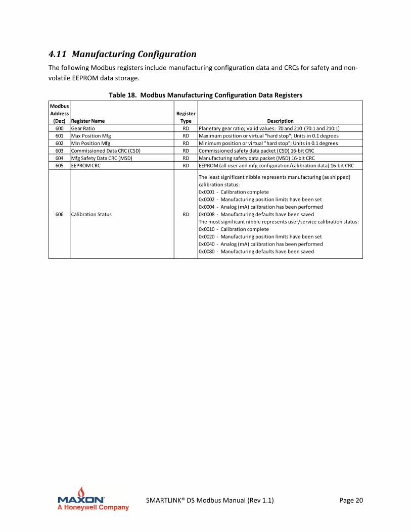
4.11 ManufacturingConfigurationThe following Modbus registers include manufacturing configuration data and CRCs for safety and non‐
volatile EEPROM data storage.
Table 18. Modbus Manufacturing Configuration Data Registers
Modbus
Address
(Dec) Register Name
Register
Type Description
600 Gear Ratio RD Planetary gear ratio; Valid values: 70 and 210 (70:1 and 210:1)
601 Max Position Mfg RD Maximum position or virtual "hard stop"; Units in 0.1 degrees
602 Min Position Mfg RD Minimum position or virtual "hard stop"; Units in 0.1 degrees
603 Commissioned Data CRC (CSD) RD Commissioned safety data packet (CSD) 16‐bit CRC
604 Mfg Safety Data CRC (MSD) RD Manufacturing safety data packet (MSD) 16‐bit CRC
605 EEPROM CRC RD EEPROM (all user and mfg configuration/calibration data) 16‐bit CRC
606 Calibration Status RD
The least significant nibble represents manufacturing (as shipped)
calibration status:
0x0001 ‐ Calibration complete
0x0002 ‐ Manufacturing position limits have been set
0x0004 ‐ Analog (mA) calibration has been performed
0x0008 ‐ Manufacturing defaults have been saved
The most significant nibble represents user/service calibration status:
0x0010 ‐ Calibration complete
0x0020 ‐ Manufacturing position limits have been set
0x0040 ‐ Analog (mA) calibration has been performed
0x0080 ‐ Manufacturing defaults have been saved
SMARTLINK® DS Modbus Manual (Rev 1.1) Page 21
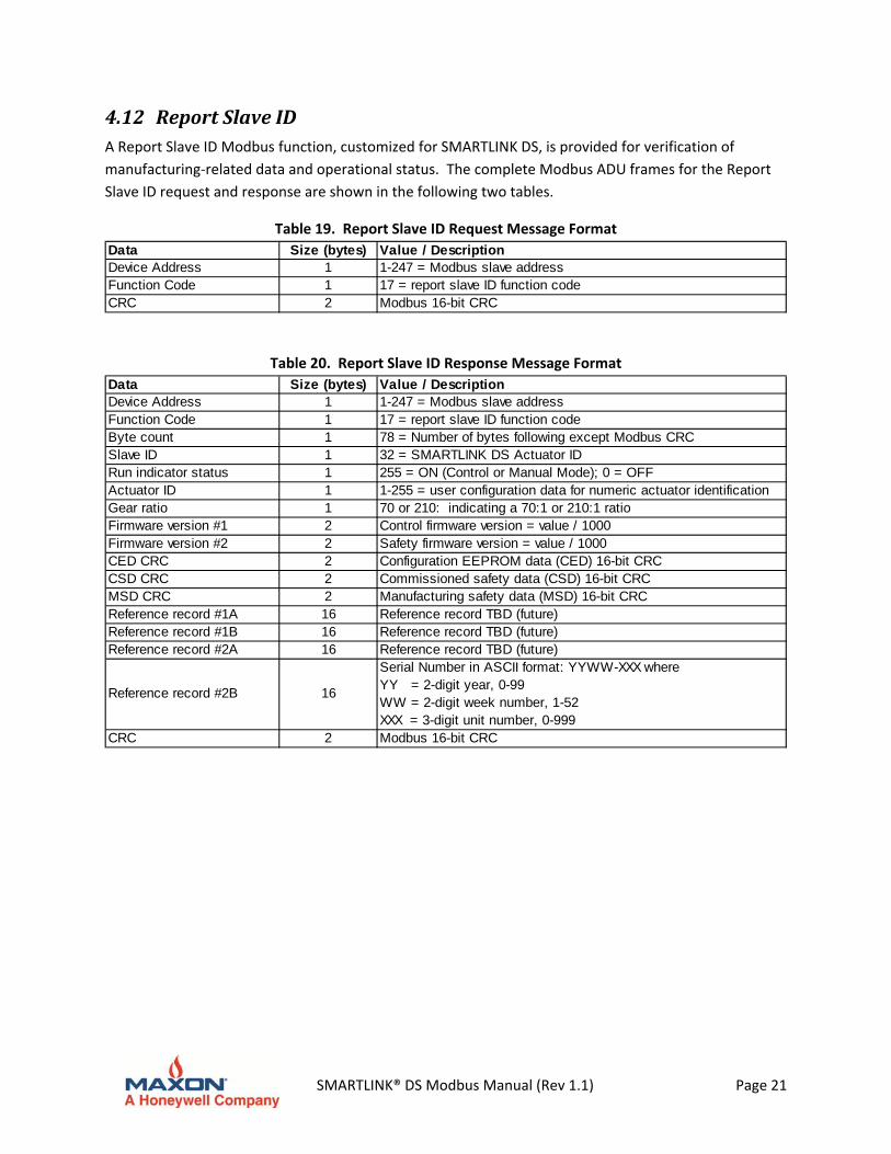
4.12 ReportSlaveIDA Report Slave ID Modbus function, customized for SMARTLINK DS, is provided for verification of
manufacturing‐related data and operational status. The complete Modbus ADU frames for the Report
Slave ID request and response are shown in the following two tables.
Table 19. Report Slave ID Request Message Format
Data Size (bytes) Value / DescriptionDevice Address 1 1-247 = Modbus slave addressFunction Code 1 17 = report slave ID function codeCRC 2 Modbus 16-bit CRC
Table 20. Report Slave ID Response Message Format
Data Size (bytes) Value / DescriptionDevice Address 1 1-247 = Modbus slave addressFunction Code 1 17 = report slave ID function codeByte count 1 78 = Number of bytes following except Modbus CRCSlave ID 1 32 = SMARTLINK DS Actuator IDRun indicator status 1 255 = ON (Control or Manual Mode); 0 = OFF Actuator ID 1 1-255 = user configuration data for numeric actuator identification Gear ratio 1 70 or 210: indicating a 70:1 or 210:1 ratioFirmware version #1 2 Control firmware version = value / 1000Firmware version #2 2 Safety firmware version = value / 1000CED CRC 2 Configuration EEPROM data (CED) 16-bit CRCCSD CRC 2 Commissioned safety data (CSD) 16-bit CRCMSD CRC 2 Manufacturing safety data (MSD) 16-bit CRCReference record #1A 16 Reference record TBD (future)Reference record #1B 16 Reference record TBD (future)Reference record #2A 16 Reference record TBD (future)
Reference record #2B 16
Serial Number in ASCII format: YYWW-XXX whereYY = 2-digit year, 0-99WW = 2-digit week number, 1-52XXX = 3-digit unit number, 0-999
CRC 2 Modbus 16-bit CRC
SMARTLINK® DS Modbus Manual (Rev 1.1) Page 22
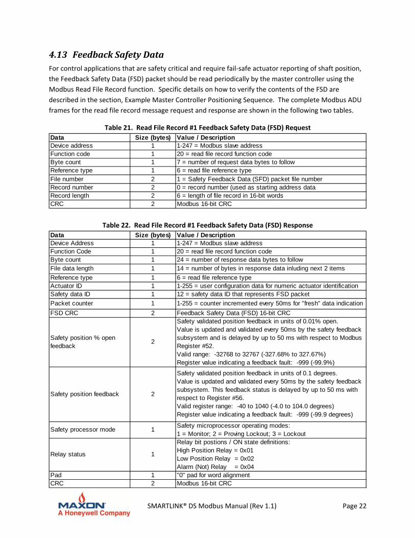
4.13 FeedbackSafetyDataFor control applications that are safety critical and require fail‐safe actuator reporting of shaft position,
the Feedback Safety Data (FSD) packet should be read periodically by the master controller using the
Modbus Read File Record function. Specific details on how to verify the contents of the FSD are
described in the section, Example Master Controller Positioning Sequence. The complete Modbus ADU
frames for the read file record message request and response are shown in the following two tables.
Table 21. Read File Record #1 Feedback Safety Data (FSD) Request
Data Size (bytes) Value / DescriptionDevice address 1 1-247 = Modbus slave addressFunction code 1 20 = read file record function codeByte count 1 7 = number of request data bytes to followReference type 1 6 = read file reference typeFile number 2 1 = Safety Feedback Data (SFD) packet file numberRecord number 2 0 = record number (used as starting address dataRecord length 2 6 = length of file record in 16-bit wordsCRC 2 Modbus 16-bit CRC
Table 22. Read File Record #1 Feedback Safety Data (FSD) Response
Data Size (bytes) Value / DescriptionDevice Address 1 1-247 = Modbus slave addressFunction Code 1 20 = read file record function codeByte count 1 24 = number of response data bytes to followFile data length 1 14 = number of bytes in response data inluding next 2 items
Reference type 1 6 = read file reference typeActuator ID 1 1-255 = user configuration data for numeric actuator identification Safety data ID 1 12 = safety data ID that represents FSD packet
Packet counter 1 1-255 = counter incremented every 50ms for "fresh" data indication
FSD CRC 2 Feedback Safety Data (FSD) 16-bit CRC
Safety position % open feedback
2
Safety validated position feedback in units of 0.01% open.Value is updated and validated every 50ms by the safety feedback subsystem and is delayed by up to 50 ms with respect to Modbus Register #52.Valid range: -32768 to 32767 (-327.68% to 327.67%)Register value indicating a feedback fault: -999 (-99.9%)
Safety position feedback 2
Safety validated position feedback in units of 0.1 degrees.Value is updated and validated every 50ms by the safety feedback subsystem. This feedback status is delayed by up to 50 ms with respect to Register #56.Valid register range: -40 to 1040 (-4.0 to 104.0 degrees)Register value indicating a feedback fault: -999 (-99.9 degrees)
Safety processor mode 1Safety microprocessor operating modes: 1 = Monitor; 2 = Proving Lockout; 3 = Lockout
Relay status 1
Relay bit postions / ON state definitions: High Position Relay = 0x01Low Position Relay = 0x02Alarm (Not) Relay = 0x04
Pad 1 "0" pad for word alignmentCRC 2 Modbus 16-bit CRC
SMARTLINK® DS Modbus Manual (Rev 1.1) Page 23
5 MasterControllerPositioningTechniquesThe following Modbus master controller positioning techniques are recommended for applications in which there is a requirement for detection of an actuator failure that could result in false reporting of the output shaft position. This is a common requirement for a PLC or DCS‐based system that controls air and fuel valve actuators within a parallel positioning combustion system. In addition to the application recommendations below, the master controller must have the hardware and software capability to place the system in a fail‐safe state after an actuator failure is detected. Specifically, the system should be designed in a manner that complies with software/functional safety requirements such as ANSI/UL 1998 Software Class 2, UL/IEC 60730‐1 Software Class C, or other similar safety standards as appropriate for the end application.
5.1 PositionSetpointSourceFor continuous position control by an upstream master controller, the position setpoint source parameter of SMARTLINK DS should be configured during unit commissioning for serial Modbus control. Refer to the description of the Setpoint Source register #10 in the User Configuration section above or the SMARTLINK®DS Intelligent Control Actuator Series Technical Catalog for local display commissioning of this parameter.
5.2 PositionCommandThe serial position command (in 0.1 degree units), register #55, should be used for commanding the actuator to a new position. This register is less ambiguous than commanding the actuator via the position % open command, register #51. The actual position of the shaft will be different for the same percent open command if the min or max travel configuration is changed after initial actuator commissioning.
5.3 PositionFeedbackAfter the position command register #55 is sent, the master controller should poll the actuator with a multiple register read (of three contiguous registers): Register #55, Serial Position Command, Register #56, Control Position Feedback, and Register #57, Safety Position Feedback. This poll is used to verify the position command and the actual position of the shaft using both feedback values for comparison. In addition, the Feedback Safety Data (FSD) packet should be periodically read back to validate the feedback data in a fail‐safe manner.
SMARTLINK® DS Modbus Manual (Rev 1.1) Page 24
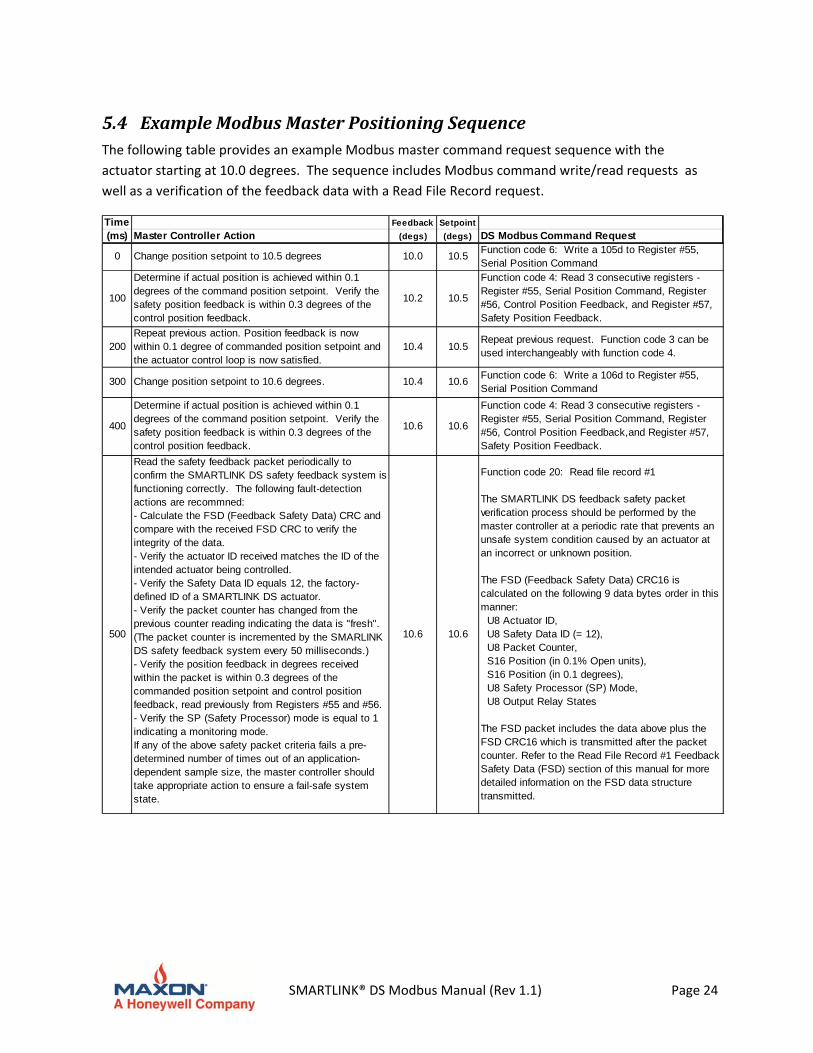
5.4 ExampleModbusMasterPositioningSequenceThe following table provides an example Modbus master command request sequence with the
actuator starting at 10.0 degrees. The sequence includes Modbus command write/read requests as
well as a verification of the feedback data with a Read File Record request.
Time Feedback Setpoint
(ms) Master Controller Action (degs) (degs) DS Modbus Command Request
0 Change position setpoint to 10.5 degrees 10.0 10.5Function code 6: Write a 105d to Register #55, Serial Position Command
100
Determine if actual position is achieved within 0.1 degrees of the command position setpoint. Verify the safety position feedback is within 0.3 degrees of the control position feedback.
10.2 10.5
Function code 4: Read 3 consecutive registers - Register #55, Serial Position Command, Register #56, Control Position Feedback, and Register #57, Safety Position Feedback.
200Repeat previous action. Position feedback is now within 0.1 degree of commanded position setpoint and the actuator control loop is now satisfied.
10.4 10.5Repeat previous request. Function code 3 can be used interchangeably with function code 4.
300 Change position setpoint to 10.6 degrees. 10.4 10.6Function code 6: Write a 106d to Register #55, Serial Position Command
400
Determine if actual position is achieved within 0.1 degrees of the command position setpoint. Verify the safety position feedback is within 0.3 degrees of the control position feedback.
10.6 10.6
Function code 4: Read 3 consecutive registers - Register #55, Serial Position Command, Register #56, Control Position Feedback,and Register #57, Safety Position Feedback.
500
Read the safety feedback packet periodically to confirm the SMARTLINK DS safety feedback system is functioning correctly. The following fault-detection actions are recommned:- Calculate the FSD (Feedback Safety Data) CRC and compare with the received FSD CRC to verify the integrity of the data.- Verify the actuator ID received matches the ID of the intended actuator being controlled.- Verify the Safety Data ID equals 12, the factory-defined ID of a SMARTLINK DS actuator. - Verify the packet counter has changed from the previous counter reading indicating the data is "fresh". (The packet counter is incremented by the SMARLINK DS safety feedback system every 50 milliseconds.)- Verify the position feedback in degrees received within the packet is within 0.3 degrees of the commanded position setpoint and control position feedback, read previously from Registers #55 and #56. - Verify the SP (Safety Processor) mode is equal to 1 indicating a monitoring mode.If any of the above safety packet criteria fails a pre-determined number of times out of an application-dependent sample size, the master controller should take appropriate action to ensure a fail-safe system state.
10.6 10.6
Function code 20: Read file record #1
The SMARTLINK DS feedback safety packet verification process should be performed by the master controller at a periodic rate that prevents an unsafe system condition caused by an actuator at an incorrect or unknown position.
The FSD (Feedback Safety Data) CRC16 is calculated on the following 9 data bytes order in this manner: U8 Actuator ID, U8 Safety Data ID (= 12), U8 Packet Counter, S16 Position (in 0.1% Open units), S16 Position (in 0.1 degrees), U8 Safety Processor (SP) Mode, U8 Output Relay States
The FSD packet includes the data above plus the FSD CRC16 which is transmitted after the packet counter. Refer to the Read File Record #1 Feedback Safety Data (FSD) section of this manual for more detailed information on the FSD data structure transmitted.