smart step assembly instr uctions - go main … · · 2014-03-30smart step components qty a1)...
TRANSCRIPT
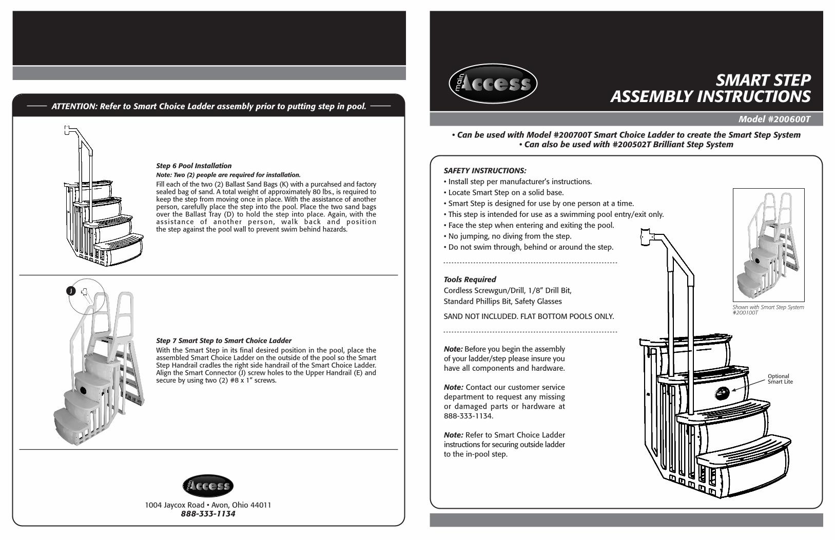
SAFETY INSTRUCTIONS:• Install step per manufacturer’s instructions.• Locate Smart Step on a solid base.• Smart Step is designed for use by one person at a time.• This step is intended for use as a swimming pool entry/exit only.• Face the step when entering and exiting the pool.• No jumping, no diving from the step.• Do not swim through, behind or around the step.
Model #200600T
SMART STEPASSEMBLY INSTRUCTIONS
• Can be used with Model #200700T Smart Choice Ladder to create the Smart Step System• Can also be used with #200502T Brilliant Step System
1004 Jaycox Road • Avon, Ohio 44011888-333-1134
Tools RequiredCordless Screwgun/Drill, 1/8” Drill Bit,Standard Phillips Bit, Safety Glasses
SAND NOT INCLUDED. FLAT BOTTOM POOLS ONLY.
OptionalSmart Lite
Step 6 Pool InstallationNote: Two (2) people are required for installation.
Fill each of the two (2) Ballast Sand Bags (K) with a purcahsed and factorysealed bag of sand. A total weight of approximately 80 lbs., is required tokeep the step from moving once in place. With the assistance of anotherperson, carefully place the step into the pool. Place the two sand bagsover the Ballast Tray (D) to hold the step into place. Again, with theass is tance of another person, walk back and posi t ionthe step against the pool wall to prevent swim behind hazards.
Step 7 Smart Step to Smart Choice LadderWith the Smart Step in its final desired position in the pool, place theassembled Smart Choice Ladder on the outside of the pool so the SmartStep Handrail cradles the right side handrail of the Smart Choice Ladder.Align the Smart Connector (J) screw holes to the Upper Handrail (E) andsecure by using two (2) #8 x 1” screws.
Note: Before you begin the assemblyof your ladder/step please insure youhave all components and hardware.
Note: Contact our customer servicedepartment to request any missingor damaged parts or hardware at888-333-1134.
Note: Refer to Smart Choice Ladderinstructions for securing outside ladderto the in-pool step.
Shown with Smart Step System#200100T
ATTENTION: Refer to Smart Choice Ladder assembly prior to putting step in pool.
J

Smart Step Components QtyA1) Upper Step Tread 1A2) Lower Step Tread 1B1) Upper Left Side Riser 1B2) Lower Left Side Riser 1C1) Upper Right Side Riser 1C2) Lower Right Side Riser 1D) Ballast Tray 1E) Upper Handrail 1F) Top Step Support Brace 1G) Mid Riser Support Brace 1I) Lower Handrails 2J) Smart Connector 1
Hardware Kit (not shown) QtyK) Ballast Sand Bags 2L) #8 x 1” Screws 8M) #14 x 1-1/4 Screws 4
SMART STEP ASSEMBLY INSTRUCTIONS
ST E P BY ST E P AS S E M B LY I N ST R U C T I O N S
Model #200600T
Step 3 Upper and Lower AssemblyStand the Lower Step & Riser Assembly and Upper Step & Riser Assemblyin the upright position as shown. Insert the tabs on the Lower Step Tread(A2) into the slots on the Upper Step Tread (A1).
Step 4 Step BracesLocate the Top Step Support Brace (F). Position the brace with the openside facing toward the front of the step. Be sure to position the brace sothe notch on each end will align and be flush with the top side of eachriser. Locate the Mid-Riser Support Brace (G). Position the brace with theopen side facing down. Snap down and secure the brace over the tabswhich are located in the middle back section of each riser. Snap in BallastTray (D) over riser tabs.
Step 5 Handrail AssemblyInsert the two (2) Lower Handrails (I) into the step tread sockets on theleft side of the second and third steps. Secure each handrail with two (2)#14 x 1-1/4” screws (M) on the outer side of the Left Side Riser. Securethe Upper Handrail (E) to the Lower Handrails (I) and secure with two(2) #8 x 1” screws.
Using four (4) #8 x 1” screws, secure the top of the Lower Step Tread (A2)to the risers. Screw locators are provided. Be sure the screws secure theLower Step Tread (A2) to the side risers.
Continued on back page
D
G
J
I
A1
A2
E
F
Step 1 Lower Step and Riser AssemblyA second person will be of assistance in holding the siderisers in place as it is being secured to the step treads.Position the Lower Step Tread (A2) on its side as shown.Align the “mushroom head” snaps with holes on the LowerRight Side Riser (C2). Once all snaps and alignment holesare in position, firmly hold down the riser and strike witha rubber mallet to secure the “mushroom heads” to theriser. Flip over the assembly and repeat with the Lower LeftSide Riser (B2).
C1
C2
B2
C2
A2
Step 2 Upper Step and Riser AssemblyPosition the Upper Step Tread (A1) on its side as shown. Align the “mushroomhead” snaps with holes on the Upper Right Side Riser (C1). Once all snapsand alignment holes are in position, firmly hold down the riser and strikewith a rubber mallet to secure the “mushroom heads” to the riser. Flip overthe assembly and repeat with the Upper Left Side Riser (B1).
B1
A1
C1
A1
A2
D
G
F
I
A2
E
I