smart parking - libelium.com · smart parking has 2 sleep modes: day mode and night mode. the...
TRANSCRIPT

waspmote
Smart ParkingTechnical Guide

-2- v7.6
Document version: v7.6 - 05/2018 © Libelium Comunicaciones Distribuidas S.L.
INDEX1. Introduction ..........................................................................................................................5
2. General ..................................................................................................................................62.1. General and safety information ...................................................................................................... 62.2. Conditions of use .............................................................................................................................. 6
3. Hardware ...............................................................................................................................73.1. Hardware description ....................................................................................................................... 73.2. Regions supported ............................................................................................................................ 8
3.2.1. LoRaWAN regions ..................................................................................................................83.2.2. Sigfox regions ........................................................................................................................8
3.3. Power consumption.......................................................................................................................... 8
4. How the node works .............................................................................................................9
5. Sleep modes .........................................................................................................................105.1. Day mode ......................................................................................................................................... 105.2. Night mode ...................................................................................................................................... 11
6. Transmission modes ...........................................................................................................12
7. Frames ..................................................................................................................................137.1. Firmware version v3.x.x ................................................................................................................. 13
7.1.1. Using the RSSI to get a better detection accuracy ..........................................................157.1.2. Frame ....................................................................................................................................167.1.3. Info frame .............................................................................................................................177.1.4. Keep-Alive frame .................................................................................................................177.1.5. Daily update frame .............................................................................................................187.1.6. Start frame 1 ........................................................................................................................187.1.7. Start frame 2 ........................................................................................................................197.1.8. Service, RSSI and Downlink frames ...................................................................................19
7.2. Firmware version v2.x.x ................................................................................................................. 207.2.1. Info frame .............................................................................................................................207.2.2. Keep-Alive frame .................................................................................................................217.2.3. Daily update frame .............................................................................................................217.2.4. Error frame ...........................................................................................................................227.2.5. Start frames .........................................................................................................................23
7.3. Firmware version v1.x.x ................................................................................................................. 247.3.1. Info frame .............................................................................................................................247.3.2. Keep-Alive frame .................................................................................................................25
Index

-3- v7.6
7.3.3. Daily update frame .............................................................................................................257.3.4. Error frame ...........................................................................................................................267.3.5. Start frames .........................................................................................................................27
8. Smart Devices App ..............................................................................................................288.1. Installation ....................................................................................................................................... 288.2. Upgrading ........................................................................................................................................ 288.3. Smart Parking .................................................................................................................................. 29
8.3.1. Programmer .........................................................................................................................298.3.2. Firmware upgrade ...............................................................................................................318.3.3. Configuration .......................................................................................................................33
9. Callback Server ....................................................................................................................349.1. Installation ....................................................................................................................................... 349.2. Deploying ......................................................................................................................................... 359.3. Making the server accessible from anywhere ............................................................................. 369.4. Upgrading ........................................................................................................................................ 369.5. Callback Configurator ..................................................................................................................... 379.6. Background process ....................................................................................................................... 409.7. Customer’s improvements............................................................................................................. 40
9.7.1. How to extend the callback configurator and background process .............................409.7.2. How to develop a cloud platform ......................................................................................419.7.3. API calls .................................................................................................................................41
10. Developing the network...................................................................................................4410.1. Deployment of the motes ............................................................................................................ 4410.2. Interference of other vehicles ..................................................................................................... 45
11. Device Installation ............................................................................................................4611.1. Installation field requirements .................................................................................................... 4611.2. Assembly and set up .................................................................................................................... 4711.3. How to close the Smart Parking enclosure to keep the waterproof IP68 features .............. 4911.4. Installation and boot .................................................................................................................... 50
11.4.1. Placing the nodes on the surface ....................................................................................5011.4.2. Placing the nodes under the ground for special deployments ...................................57
11.5. Configuring the parking nodes in the callback server .............................................................. 63
12. Callback Services ...............................................................................................................6412.1. Sigfox .............................................................................................................................................. 64
12.1.1. Device configuration .........................................................................................................6412.1.2. Server configuration .........................................................................................................68
12.2. Loriot HTTP .................................................................................................................................... 6912.2.1. Device configuration .........................................................................................................6912.2.2. Server configuration .........................................................................................................71
Index

-4- v7.6
12.3. Loriot websocket ........................................................................................................................... 7212.3.1. Device configuration .........................................................................................................7212.3.2. Server configuration .........................................................................................................7312.3.3. Start the web-socket connection .....................................................................................74
12.4. Actility ............................................................................................................................................. 7512.4.1. Device configuration .........................................................................................................7512.4.2. Server configuration .........................................................................................................80
12.5. Saving the information received ................................................................................................. 8112.6. How to develop a new service ..................................................................................................... 81
13. Troubleshooting ................................................................................................................8713.1. Windows does not recognize USB ports ................................................................................... 8713.2. How to know the port where the device is plugged in ............................................................. 9013.3. I cannot load nor save the configuration in the node .............................................................. 90
14. Documentation changelog ..............................................................................................91
15. Certifications .....................................................................................................................93
16. Disposal and recycling ......................................................................................................94

-5- v7.6
Introduction
1. IntroductionThe new version of Smart Parking, the solution for Smart Cities that allows citizens to detect available parking spots.
The new device is easier and cheaper to deploy as it is mounted on the road surface. Unlike most market versions, it does not need to dig a hole in the ground for installation, reducing installation time from 30 to 5 minutes and allowing to be replaced by another unit in case of maintenance in just 10 minutes.
The smaller size -reduced over 50%-, its higher accuracy and reliability, and the faster time of detection, besides the independence from temperature are also important features of new Smart Parking device.
New sensor system is fully compatible with LPWAN radio technologies -LoRaWAN and Sigfox- to enable long range and low power consumption. It can be connected with both radios for the European 868 MHz band and for the 900-930 MHz band (US / Canada). One unique feature of the system is that it allows to use both radio technologies at the same time or changing from one to the other using the manager system from the Cloud.
With the new sensor system, one base station can give service to thousands of devices around a range of several kilometers in urban environment. This fact provides lower costs of installation since the number of base stations can be dramatically reduced. Besides, the new sensor model has been optimized for really low-power operation, so the battery lifetime is extended up to 10 years easily.
The new Smart Parking node has been granted with the CE / FCC / IC marks and provides a robust software which works out-of-the-box. Developers do not have to cope with programming the nodes, they just have to specify the values of key parameters in the firmware such as working cycle or night mode to be ready to work. Remote management and bidirectional communication allows to change several parameters of the nodes from the Cloud. This means we can reprogram thousands of nodes by just setting the right values from our web browser in the management platform.

-6- v7.6
General
2. General 2.1. General and safety information • In this section, the term “Waspmote” encompasses both the Waspmote device itself and it enclosure. • Read through the document “General Conditions of Libelium Sale and Use”. • Do not allow contact of metallic objects with the electronic part to avoid injuries and burns. • NEVER submerge the device in any liquid with the enclosure open. • Keep the device in a dry place and away from any liquid which may spill. • Waspmote consists of highly sensitive electronics which is accessible to the exterior, handle with great care
and avoid bangs or hard brushing against surfaces. • Check the product specifications section for the maximum allowed power voltage and amperage range and
consequently always use a current transformer and a battery which works within that range. Libelium is only responsible for the correct operation of the device with the batteries, power supplies and chargers which it supplies.
• Keep the device within the specified range of temperatures in the specifications section. • Do not connect or power the device with damaged cables or batteries. • Place the device in a place only accessible to maintenance personnel (a restricted area). • Keep children away from the device in all circumstances. • If there is an electrical failure, disconnect the main switch immediately and disconnect that battery or any
other power supply that is being used. • If a hardware failure occurs, consult the Libelium Web Development section. • Check that the frequency and power of the communication radio modules together with the integrated
antennas are allowed in the area where you want to use the device.
2.2. Conditions of use • Read the “General and Safety Information” section carefully and keep the manual for future consultation. • Use Waspmote in accordance with the electrical specifications and the environment described in the
“Hardware” section of this manual. • Do not place Waspmote in contact with metallic surfaces; they could cause short-circuits which will permanently
damage it. • IMPORTANT It is the responsibility of the installer to find out about restrictions of use for frequency bands in
each country and act in accordance with the given regulations. Libelium Comunicaciones Distribuidas S.L does not list the entire set of standards that must be met for each country.
• For further information go to: - CEPT ERC 70-03E - Technical Requirements, European restrictions and general requirements: http://www.
erodocdb.dk/ - R&TTE Directive - Equipment requirements, placement on market: http://www.erodocdb.dk/
• Further information you may need can be found at: http://www.libelium.com/development/waspmote • The “General Conditions of Libelium Sale and Use” document can be found at:
http://www.libelium.com/development/waspmote/technical_service

-7- v7.6
Hardware
3. Hardware3.1. Hardware description
Figure: Smart Parking
Versions
SP-EU: Smart Parking EU SP-US: Smart Parking US SP-AAPL: Smart Parking AU / APAC / LATAM SP-IN: Smart Parking IN
Operating frequency
Sigfox radio for Europe: 868.0 to 869.7 MHzLoRaWAN radio for Europe: 863.0 to 870.0 MHzSigfox radio for USA: 902.0 to 928.0 MHzLoRaWAN radio for USA: 902.0 to 928.0 MHzSigfox radio for AU / APAC / LATAM: 920.0 MHzLoRaWAN radio for AU: 915.2 to 927.8 MHz LoRaWAN radio for India: 865 to 867 MHz
Power supply Built-in Lithium batteries, expected lifetime of 4-6 years*Antenna IncludedDetection MagneticMounting Over the floorDimensions 230 mm diameter, 28 mm height
Protection IP68 strictly under right closing (see section “Device installation”)
Operating temperature -20 to +65 °C
* Under normal circumstances and dependent on settings
Figure: Smart Parking main characteristics

-8- v7.6
Hardware
3.2. Regions supported
3.2.1. LoRaWAN regions
Region Supported byEU 863-870 MHz ISM Band (Europe) Smart Parking EU
US 902-928 MHz ISM Band (United States) Smart Parking USCN 779-787 MHz ISM Band (China) Coming 2018-2019
AU 915-928 MHz ISM Band (Australia) Smart Parking AU / APAC / LATAMCN 470-510 MHz ISM Band (China) Coming 2018-2019
AS 923 MHz ISM Band (Asia) Coming 2018-2019KR 920-923 MHz ISM Band (South Korea) Coming 2018-2019
IN 865-867 MHz ISM Band (India) Smart Parking IN433 MHz ISM Band (Worldwide) Coming 2018-2019
Figure: Smart Parking region standards for LoRaWAN protocol
3.2.2. Sigfox regions
Region Supported byEurope, Oman, Iran, South Africa, UAE Smart Parking EU
USA, Mexico, Brazil Smart Parking USAustralia, New Zealand, Singapore, Taiwan, Hong Kong, Thailand, Colombia, Argentina, Costa Rica,
Malaysia, Ecuador, Panama, El Salvador, ChileSmart Parking AU / APAC / LATAM
Figure: Smart Parking region standards for Sigfox protocol
3.3. Power consumptionConsumption
Measuring sensor TBDTransmission Sigfox TBDTransmission LoRaWAN TBDSleep state 25 µABattery self discharge < 1% month at +20 ºC
Battery type Lithium non-rechargeable battery, 3.6 V, 10.4 A·h
Figure: Smart Parking power consumption

-9- v7.6
How the node works
4. How the node works
Figure: Basic working loop diagram
As the diagram indicate, the basic loop of the node consists in reading the sensor and sending a frame when the parking slot changes its status. Then, it sleeps a desired time and starts the loop again.
Some events can force the node to send a frame to the cloud. If a desired time elapsed since the last radio transmission, the node will send a Keep-Alive frame. This frame only contains basic data from the node (parking slot status and battery status). It is useful to know that there are no changes in the slot, but the node is still working. The node also will send a frame each 24 hours with the working data of the day.
Figure: Extended loop diagram

-10- v7.6
Sleep modes
5. Sleep modesSmart Parking has 2 sleep modes: day mode and night mode. The second one has been developed to use when the parking slot is expected to have fewer changes (i.e. at night). Each mode has its own configuration parameters. The figure below shows an example for the node transmissions in a day. The time zone between 6 AM and 12 AM (in light gray) indicates that the node is working in day mode. In this mode, the sampling of the parking slot is made more regular (1 minute) and the Keep-Alive is only 2 hours. In the dark gray zone, from 12 AM to 6 AM, the node is working in night mode. As is shown in the example, the sampling time is greater (5 minutes) and the Keep-Alive increases too (3 hours).
Example configuration:
Parameter ConfigurationSleep time 1 minuteKeep-Alive 2 hours
Night Mode start hour 00 hoursNight Mode duration 6 hours
Night Mode Sleep Time 5 minutesNight Mode Keep-Alive 3 hours
Figure: Example configuration
Figure: Day and night modes example
5.1. Day modeIt is the basic working mode and it has 2 configurable parameters:
• Sleep time: Sleep time between consecutive sensor measurements. 1 minute option is configured by default. • Keep-Alive: Elapsed time since last transmission to trigger a Keep-Alive frame. 0.5 hours option is configured
by default. This frame only contains basic data from the node (parking slot status and battery status). It is useful to know that there are no changes in the slot, but the node still working. This mode can be disabled using both the USB Programmer or the Remote Manager.

-11- v7.6
Sleep modes
5.2. Night mode
The Smart Parking EU, Smart Parking US and Smart Parking IN firmwares provide the “night mode”. However, the Smart Parking AU / APAC / LATAM firmware v3.0.2 and greater versions do not provide the “night mode” due to memory restrictions. So, in that specific case the node will always work in “day mode”.
This mode has been developed to use when the parking slot is expected to have fewer changes (i.e. at night). It has 4 configurable parameters:
• Night Mode start hour: Beginning hour of the night mode. 22 hours option is configured by default. • Night Mode duration: Night mode duration time. 8 hours option is configured by default. • Night Mode Sleep Time: Sleep time between consecutive sensor measurements (during night mode). 5
minutes option is configured by default. • Night Mode Keep-Alive: Elapsed time since last transmission to trigger a Keep-Alive frame (during night
mode). 1 hour option is configured by default. This frame only contains basic data from the node (parking slot status and battery status). It is useful to know that there is no change in the slot, but the node is still working.
This mode can be disabled using both the USB Programmer or the Remote Manager.

-12- v7.6
Transmission modes
6. Transmission modesSmart Parking has 5 transmission modes allowing the user to choose between Sigfox, LoRaWAN and their combinations:
• Sigfox. This mode only uses the Sigfox radio to send the data collected by the node. This mode is selected by default.
• LoRaWAN. This mode only uses the LoRaWAN radio to send the data collected by the node. • Sigfox + LoRaWAN. In this mode the data collected is sent using the 2 radios. It is recommended to test the
node with the two transmission technologies. • Sigfox → LoRaWAN. This mode uses Sigfox radio as primary radio. If there is an issue with the Sigfox radio, it
will use LoRaWAN to send the frames. • LoRaWAN → Sigfox. This mode uses LoRaWAN radio as primary radio. If there is an issue with the LoRaWAN
radio, it will use Sigfox to send the frames.

-13- v7.6
Frames
7. Frames7.1. Firmware version v3.x.xThe firmware v3.x.x adds new features to the Smart Parking product in the LoRaWAN-only configuration. The LoRaWAN back-end provides the best RSSI received from all packets. The received packet’s RSSI experiences changes if a vehicle is positioned over the node. Therefore, the Smart Parking solution takes advantage of it. After setting-up the device on the field, several RSSI measurements are performed so a reference value is stored. For this reason, it is important to keep in mind that the parking should be empty when the node installation is done. For further information please refer to the “Developing the network” and “Device Installation” sections.
Currently, the Sigfox back-end is not able to provide the best received RSSI to a third party cloud system, so the implementation is not performed for any device configuration which adds Sigfox transmissions. In other words, if Sigfox is configured to be the main or secondary transmission mode, the RSSI feature will not be executed.
The firmware v3.x.x is available for the next versions of the Smart Parking device:
• Smart Parking EU • Smart Parking US • Smart Parking AU / APAC / LATAM • Smart Parking IN
The next table shows some features included in each v3.x.x firmware version:
Feature
Firmware v3.0.1 Firmware v3.0.2
Smart Parking EU v3.0.1
or Smart Parking
US v3.0.1
Smart Parking AU / APAC /
LATAM v3.0.1
Smart Parking EU v3.0.2
or Smart Parking
US v3.0.2
Smart Parking AU / APAC /
LATAM v3.0.2
Smart Parking IN v3.0.2
“Sigfox” transmission mode Optional Mandatory Optional Optional Not available
“LoRaWAN” transmission mode Optional Not available Optional Optional Mandatory
“Sigfox + LoRaWAN” transmission mode Optional Not available Optional Optional Not available
“Sigfox → LoRaWAN” transmission mode Optional Not available Optional Optional Not available
“LoRaWAN → Sigfox” transmission mode Optional Not available Optional Optional Not available
RSSI feature for “LoRaWAN” transmission
modeMandatory1 Not available Optional2 Optional2 Optional2
Night mode feature Optional Optional Optional Not available Optional
1: This feature is always enabled and cannot be disabled. The Callback Server is always needed. 2: The user is free to activate this feature. If activated, the Callback Server becomes needed.
If the “RSSI feature” is enabled, the user must keep in mind that the Callback Server is needed. In that case, if the Callback Server is not installed and working properly, the user will experience erratic behavior in the node.
Firmware v3.0.2 is highly recommended in order to avoid this behavior. This firmware solves the situation where the user’s Callback Server is not correctly operating: if the node is configured for LoRaWAN-only mode and no

-14- v7.6
Frames
Callback Server has been installed, the initial RSSI procedure will not be completed; the node will cancel the process and continue working without the RSSI feature.

-15- v7.6
Frames
7.1.1. Using the RSSI to get a better detection accuracy
According to tests performed by Libelium and customers, the current detection rate of our Smart Parking node is on average the 90%. The detection method relies upon a 3-axes magnetic field sensor: when a car parks, its big mass of metal modifies the Earth’s natural magnetic field around the node. However, this method is not perfect because in some cases the change in the magnetic field is not big enough to be understood as a car status change. In particular, some cars are more complicated to detect than others, probably because of their construction materials, its distribution or the height of the chassis.
Smart Parking competition normally does not tells the detection rate. Few companies give this information or just say values not tested.
Libelium is committed with the continuous improvement, so we wanted to explore one idea that seemed reasonable: the presence of a big mass of a car over the node necessarily affects to the radio transmission signal received on the Base Stations.
The RSSI (received signal strength indicator) is a telecommunication parameter which indicates how much power contains the signal received. The power density of any radio-frequency wave decreases its power from the moment it goes out of the antenna. There are several reasons for that attenuation. First, the propagation loss, known as the logical expansion of power through space. Second, any obstacle in the path of the wave will cause a reflection and absorption of energy.
Our developers have implemented new software to take advantage of this new detection method to increase the probability to detect one car above the node. The algorithm runs on the cloud and helps to detect even problematic cars. So we are using the LoRaWAN radio present in the Smart Parking node to support the vehicle detection: higher detection with no additional hardware.
The picture below shows clearly that when the slot is occupied (blue line up), the RSSI is notably lower (around -120 dBm) than when the slot is free (-109 dBm).
Nodo 1 | 1 week1
-140
-130
-120
-110
-100
StateRSSI
0
Figure: Effect of the presence of a car above the node on the RSSI on a Base Station

-16- v7.6
Frames
7.1.2. Frame
Smart Parking node can send several defined frames. All frames are 11 bytes length and they are the same for Sigfox and LoRaWAN. Bytes 0 and 1 are common for all frames.
Byte 0 has the basic information of the node and frame.
Byte Bit Name Description
0
7 Parking slot status'0' indicates that the parking slot is empty'1' indicates that the slot is in occupied
6 Battery state
'0' indicates that the battery has a good level of charge‘1’ indicates that the battery has little charge and it will be necessary to change it. When the battery has little charge it is possible that the node does not work properly and the radios fail sending the frames.
5-4 Reserved Reserved bits. Do not consider.3
Frame type
0 – Info frame1 – Keep-Alive frame2 – Daily update frame3 – Reserved4 – Start frame 15 – Start frame 26 – Service frame7 – Downlink frame8 – RSSI frameValues from 9 to 15 are reserved
21
0
Figure: Byte 0 description
Byte 1 is a frame counter, it goes from 0 to 255. This byte can be used to detect lost frames (sent by the node but not received).
Byte Name Description1 Frame counter Frame counter number from 0 to 255
Figure: Byte 1 description

-17- v7.6
Frames
7.1.3. Info frame
The node will send this kind of frame each time it detects that the parking slot changed from empty to occupied or vice-versa. The other bytes are used to give additional data to the user.
Byte Name Description0 Basic data Detailed description in the section “Frame”1 Frame counter Detailed description in the section “Frame”
2 Temperature Temperature (Celsius degrees) from the node’s internal sensor. The value of temperature is a signed integer.
3 X axis measurement MSB Raw value from the sensor associated to the X axis. The value stored in these two bytes is a 16-bit value in 2’s complement form.4 X axis measurement LSB
5 Y axis measurement MSB Raw value from the sensor associated to the Y axis. The value stored in these two bytes is a 16-bit value in 2’s complement form.6 Y axis measurement LSB
7 Z axis measurement MSB Raw value from the sensor associated to the Z axis. The value stored in these two bytes is a 16-bit value in 2’s complement form.8 Z axis measurement LSB
9 Reserved Reserved bytes. Do not consider.
10 Battery levelBattery voltage in millivolts. To convert to millivolts use the next formula:
Figure: Table: Info frame structure
7.1.4. Keep-Alive frame
This frame is used to indicate that the parking slot has not changed, but the node is still working.
Byte Name Description0 Basic data Detailed description in the section “Frame”1 Frame counter Detailed description in the section “Frame”2 Timestamp (hh) Current hours3 Timestamp (mm) Current minutes
4 Temperature Temperature (Celsius degrees) from the node’s internal sensor. The value of temperature is a signed integer.
5 X axis measurement MSB Raw value from the sensor associated to the X axis. The value stored in these two bytes is a 16-bit value in 2’s complement form.6 X axis measurement LSB
7 Y axis measurement MSB Raw value from the sensor associated to the Y axis. The value stored in these two bytes is a 16-bit value in 2’s complement form.8 Y axis measurement LSB
9 Z axis measurement MSB Raw value from the sensor associated to the Z axis. The value stored in these two bytes is a 16-bit value in 2’s complement form.10 Z axis measurement LSB
Figure: Keep-Alive frame structure

-18- v7.6
Frames
7.1.5. Daily update frame
This frame is sent daily at 1 AM. It contains a little summary.
Byte Name Description0 Basic data Detailed description in section “Frame”1 Frame counter Detailed description in section “Frame”2 Reserved Reserved bytes. Do not consider.3 Reserved Reserved bytes. Do not consider.4 Reserved Reserved bytes. Do not consider.5 Reserved Reserved bytes. Do not consider.6 Reserved Reserved bytes. Do not consider.7 Reserved Reserved bytes. Do not consider.8 Resets Number of resets generated in the last 24 hours9 Config_id Value of the configuration version loaded into the node
10 Reserved Reserved bytes. Do not consider.
Figure: Daily update frame structure
This frame can be deactivated using the Smart Parking USB Programmer or via radio, with the Remote Manager, setting to 0 the enable/disable daily frame bit.
The daily update frame is very special because the node waits for a response after it is sent. This response is useful for reconfiguring the node “over the air”, without physical access. Also, a second use of this response frame is to synchronize the node’s internal clock, thanks to a timestamp. This response can be configured using the remote PHP.
7.1.6. Start frame 1
This is the first frame sent by the node after starting to work in the parking slot. It is dedicated to the sensor measurement and the battery level.
Byte Name Description0 Basic data Detailed description in the section “Frame”1 Frame counter Detailed description in the section “Frame”
2 Temperature Temperature (Celsius degrees) from the node’s internal sensor. The value of temperature is a signed integer.
3 X axis measurement MSB Reference value from the sensor associated to the X axis. The value stored in these two bytes is a 16-bit value in 2’s complement form.4 X axis measurement LSB
5 Y axis measurement MSB Reference value from the sensor associated to the Y axis. The value stored in these two bytes is a 16-bit value in 2’s complement form.6 Y axis measurement LSB
7 Z axis measurement MSB Reference value from the sensor associated to the Z axis. The value stored in these two bytes is a 16-bit value in 2’s complement form.8 Z axis measurement LSB
9 Battery voltage MSB Battery voltage in millivolts. The value stored in these two bytes is an unsigned 16-bit value.10 Battery voltage LSB
Figure: Start frame number 1 structure

-19- v7.6
Frames
7.1.7. Start frame 2
This is the second frame sent after starting the device. It is used to send some parameters about the chosen configuration. The firmware version is an unsigned byte which defines the firmware version. For instance, version 7 actually means firmware v3.0.0.
Byte Name Description0 Basic data Detailed description in the section “Frame”1 Frame counter Detailed description in the section “Frame”2 FIRMWARE_VERSION Firmware version (Values are 7: v3.0.0; 6: v2.1.0; 5: v2.0.0)3 NM_START Beginning hour of the night mode4 NM_PERIOD Duration in hours of the night mode
5 NM_SLEEP_TIME Sleep time between consecutive sensor measurements (during night mode)
6 NM_KEEP_ALIVE Elapsed time since last transmission to trigger a Keep-Alive frame (during night mode)
7 RADIO_MODE Selected transmission mode between Sigfox, LoRaWAN y their combinations
8 SLEEP_TIME Sleep time between consecutive sensor measurements9 KEEP_ALIVE Elapsed time since last transmission to trigger a Keep-Alive frame
10 THRESHOLD Threshold for detecting a vehicle over the parking slot
Figure: Start frame number 2 structure
7.1.8. Service, RSSI and Downlink frames
These frames are used to manage additional features of the firmware v3.x.x. The RSSI frames are used for sending LoRaWAN packets to the LoRaWAN back-end in order to measure the device’s signal strength. The Service frame is used for requesting the RSSI data from the server. The Downlink frame is used for requesting missed downlink data as an auxiliary frame.
Byte Name Description0 Basic data Detailed description in the section “Frame”1 Frame counter Detailed description in the section “Frame”2 Timestamp (hh) Current hours3 Timestamp (mm) Current minutes
4 Temperature Temperature (Celsius degrees) from the node’s internal sensor. The value of temperature is a signed integer.
5 X axis measurement MSB Raw value from the sensor associated to the X axis. The value stored in these two bytes is a 16-bit value in 2’s complement form.6 X axis measurement LSB
7 Y axis measurement MSB Raw value from the sensor associated to the Y axis. The value stored in these two bytes is a 16-bit value in 2’s complement form.8 Y axis measurement LSB
9 Z axis measurement MSB Raw value from the sensor associated to the Z axis. The value stored in these two bytes is a 16-bit value in 2’s complement form.10 Z axis measurement LSB
Figure: Service, RSSI and Downlink frames structure

-20- v7.6
Frames
7.2. Firmware version v2.x.xSmart Parking node can send 6 defined frames. All frames are 11 bytes length and they are the same for Sigfox and LoRaWAN. Bytes 0 and 1 are common for all frames. Byte 0 has the basic information of the node and frame.
Byte Bit Name Description
0
7 Parking slot status'0' indicates that the parking slot is empty'1' indicates that the slot is in occupied
6 Battery state
'0' indicates that the battery has a good level of charge‘1’ indicates that the battery has little charge and it will be necessary to change it. When the battery has little charge it is possible that the node does not work properly and the radios fail sending the frames.
5-4 Reserved Reserved bits. Do not consider.3
Frame type
0 – Info frame1 – Keep-Alive frame2 – Daily update frame3 – Error frame4 – Start frame 15 – Start frame 2Values from 6 to 15 are reserved
21
0
Figure: Byte 0 description
Byte 1 is a frame counter, it goes from 0 to 255. This byte can be used to detect lost frames (sent by the node but not received).
7.2.1. Info frame
It is the most common frame sent by the node. The node will send this kind of frame each time it detects that the parking slot changed from empty to occupied or vice-versa. The other bytes are used to give additional data to the user.
Byte Name Description0 Basic data Detailed description in the section “Frame”1 Frame counter Detailed description in the section “Frame”
2 Temperature Temperature (Celsius degrees) from the node's internal sensor. The value of temperature is a signed integer.
3 X axis measurement MSB Raw value from the sensor associated to the X axis. The value stored in these two bytes is a 16-bit value in 2’s complement form.4 X axis measurement LSB
5 Y axis measurement MSB Raw value from the sensor associated to the Y axis. The value stored in these two bytes is a 16-bit value in 2’s complement form.6 Y axis measurement LSB
7 Z axis measurement MSB Raw value from the sensor associated to the Z axis. The value stored in these two bytes is a 16-bit value in 2’s complement form.8 Z axis measurement LSB
9-10 Reserved Reserved bytes. Do not consider.
Figure: Info frame structure

-21- v7.6
Frames
7.2.2. Keep-Alive frame
This frame is used to indicate that the parking slot has not changed, but the node is still working.
Byte Name Description0 Basic data Detailed description in section “Frame”1 Frame counter Detailed description in section “Frame”2 Timestamp (hh) Current hours3 Timestamp (mm) Current minutes
4 Temperature Temperature (Celsius degrees) from the node's internal sensor. The value of temperature is a signed integer.
5 X axis measurement MSB Raw value from the sensor associated to the X axis. The value stored in these two bytes is a 16-bit value in 2’s complement form,.6 X axis measurement LSB
7 Y axis measurement MSB Raw value from the sensor associated to the Y axis. The value stored in these two bytes is a 16-bit value in 2’s complement form.8 Y axis measurement LSB
9 Z axis measurement MSB Raw value from the sensor associated to the Z axis. The value stored in these two bytes is a 16-bit value in 2’s complement form.10 Z axis measurement LSB
Figure: Keep-Alive frame structure
7.2.3. Daily update frame
This frame is sent daily at 1 AM. It contains a little summary.
Byte Name Description0 Basic data Detailed description in section “Frame”1 Frame counter Detailed description in section “Frame”2 Sensor measurements MSB Unsigned 16 bit counter. It stores the times that the sensor is used
in the last 24 hours. 3 Sensor measurements LSB4 Sigfox transmissions MSB Unsigned 16 bit counter. It stores the times that Sigfox radio is
used in the last 24 hours. 5 Sigfox transmissions LSB6 LoRaWAN transmissions MSB Unsigned 16 bit counter. It stores the times that LoRaWAN radio is
used in the last 24 hours. 7 LoRaWAN transmissions LSB8 Resets Number of resets generated in the last 24 hours9 Config_id Value of the configuration version loaded into the node
10 Reserved Reserved bytes. Do not consider.
Figure: Daily update frame structure
This frame can be deactivated using the Smart Parking USB Programmer or via radio, with the Remote Manager, setting to 0 the enable/disable daily frame bit.
The daily update frame is very special because the node waits for a response after it is sent. This response is useful for reconfiguring the node “over the air”, without physical access. Also, a second use of this response frame is to synchronize the node’s internal clock, thanks to a timestamp. This response can be configured using the remote PHP.

-22- v7.6
Frames
7.2.4. Error frame
In some cases the node could send a frame if some internal components or processes fail.
Byte Name Description0 Basic data Detailed description in section “Frame”1 Frame counter Detailed description in section “Frame”2 Error data Detailed description below
3 Temperature Temperature (Celsius degrees) from the node's internal sensor. The value of temperature is a signed integer.
4 X axis measurement MSB Raw value from the sensor associated to the X axis. The value stored in these two bytes is a 16-bit value in 2’s complement form. 5 X axis measurement LSB
6 Y axis measurement MSB Raw value from the sensor associated to the Y axis. The value stored in these two bytes is a 16-bit value in 2’s complement form. 7 Y axis measurement LSB
8 Z axis measurement MSB Raw value from the sensor associated to the Z axis. The value stored in these two bytes is a 16-bit value in 2’s complement form. 9 Z axis measurement LSB
10 Battery levelBattery voltage in millivolts. To convert to millivolts use the next formula:
Figure: Error frame structure
Bit Name Description7-6 Reserved Reserved bits. Do not consider.
5 Error Sigfox Set to '1' when an error related with the Sigfox radio is detected. Clear when no issues detected.
4 Error LoRaWAN Set to '1' when an error related with the LoRaWAN radio is detected. Clear when no issues detected.
3 Error RTC Set to '1' when an error related with the RTC (internal clock) is detected. Clear when no issues detected.
2 Error X axis Set to '1' when an error appears in the X axis of the sensor. Clear when no issues detected.
1 Error Y axis Set to '1' when an error appears in the Y axis of the sensor. Clear when no issues detected.
0 Error Z axis Set to '1' when an error appears in the Z axis of the sensor. Clear when no issues detected.
Figure: “Error data” byte structure

-23- v7.6
Frames
7.2.5. Start frames
When the node starts to work in the parking slot, it will send 2 frames. The first one is dedicated to the sensor and the battery. The second one is used to send some parameters about the chosen configuration.
7.2.5.1. Start frame number 1
Byte Name Description0 Basic data Detailed description in section “Frame”1 Frame counter Detailed description in section “Frame”
2 Temperature Temperature (Celsius degrees) from the node's internal sensor. The value of temperature is a signed integer.
3 X axis reference MSB Reference value from the sensor associated to the X axis. The value stored in these two bytes is a 16-bit value in 2’s complement form. 4 X axis reference LSB
5 Y axis reference MSB Reference value from the sensor associated to the Y axis. The value stored in these two bytes is a 16-bit value in 2’s complement form. 6 Y axis reference LSB
7 Z axis reference MSB Reference value from the sensor associated to the Z axis. The value stored in these two bytes is a 16-bit value in 2’s complement form. 8 Z axis reference LSB
9 Battery voltage MSB Battery voltage in millivolts. The value stored in these two bytes is an unsigned 16-bit value. 10 Battery voltage LSB
Figure: Start frame number 1 structure
7.2.5.2. Start frame number 2
Byte Name Description0 Basic data Detailed description in section “Frame”1 Frame counter Detailed description in section “Frame”2 FIRMWARE_VERSION Firmware version3 NM_START Beginning hour of the night mode4 NM_PERIOD Duration in hours of the night mode5 NM_SLEEP_TIME Sleep time between consecutive sensor measurements (during night mode)
6 NM_KEEP_ALIVE Elapsed time since last transmission to trigger a Keep-Alive frame (during night mode)
7 RADIO_MODE Selected transmission mode between Sigfox, LoRaWAN y their combinations
8 SLEEP_TIME Sleep time between consecutive sensor measurements9 KEEP_ALIVE Elapsed time since last transmission to trigger a Keep-Alive frame
10 THRESHOLD Threshold for detecting a vehicle over the parking slot
Figure: Start frame number 2 structure

-24- v7.6
Frames
7.3. Firmware version v1.x.xSmart Parking node can send 6 defined frames. All frames are 12 bytes length and they are the same for Sigfox and LoRaWAN. Bytes 0 and 1 are common for all frames. Byte 0 has the basic information of the node, and frame and byte 1 is a frame counter. It can be used to detect lost frames.
Byte Bit Name Description
0
7 Parking slot status'0' indicates that the parking slot is empty'1' indicates that the slot is in occupied
6 Battery state
'0' indicates that the battery has a good level of charge'1' indicates that the battery has little charge and it will be necessary to change it. When the battery has little charge it is possible that the node does not work properly and the radios fail sending the frames.
5-4 Reserved Reserved bits. Do not consider. 3
Frame type
0 – Info frame1 – Keep-Alive frame2 – Daily update frame3 – Error frame4 – Start frame 15 – Start frame 2Values from 6 to 15 are reserved
21
0
Figure: Byte 0 description
7.3.1. Info frame
It is the most common frame sent by the node. The node will send this kind of frame each time it detects that the parking slot changed from empty to occupied or vice-versa. The other bytes are used to give additional data to the user.
Byte Name Description0 Basic data Detailed description in the section “Frame”1 Frame counter Detailed description in the section “Frame”2 Temperature MSB Raw temperature from the node's internal sensor. The value stored in
these two bytes is a 16-bit value in 2’s complement form. To convert to Celsius degrees use the next formula:
3 Temperature LSB
4 X axis measurement MSB Raw value from the sensor associated to the X axis. The value stored in these two bytes is a 16-bit value in 2’s complement form.5 X axis measurement LSB
6 Y axis measurement MSB Raw value from the sensor associated to the Y axis. The value stored in these two bytes is a 16-bit value in 2’s complement form.7 Y axis measurement LSB
8 Z axis measurement MSB Raw value from the sensor associated to the Z axis. The value stored in these two bytes is a 16-bit value in 2’s complement form.9 Z axis measurement LSB
10-11 Reserved Reserved bytes. Do not consider.
Figure: Info frame structure

-25- v7.6
Frames
7.3.2. Keep-Alive frame
This frame is used to indicate that the parking slot has not changed, but the node is still working.
Byte Name Description0 Basic data Detailed description in section “Frame”1 Frame counter Detailed description in section “Frame”2 Timestamp (hh) Current hours3 Timestamp (mm) Current minutes4 Temperature MSB Raw temperature from the node’s internal sensor. The value stored in
these two bytes is a 16-bit value in 2’s complement form. To convert to Celsius degrees use the next formula:
5 Temperature LSB
6 X axis measurement MSB Raw value from the sensor associated to the X axis. The value stored in these two bytes is a 16-bit value in 2’s complement form.7 X axis measurement LSB
8 Y axis measurement MSB Raw value from the sensor associated to the Y axis. The value stored in these two bytes is a 16-bit value in 2’s complement form.9 Y axis measurement LSB
10 Z axis measurement MSB Raw value from the sensor associated to the Z axis. The value stored in these two bytes is a 16-bit value in 2’s complement form.11 Z axis measurement LSB
Figure: Keep-Alive frame structure
7.3.3. Daily update frame
This frame is sent daily at 1 AM. It contains a little summary.
Byte Name Description0 Basic data Detailed description in section “Frame”1 Frame counter Detailed description in section “Frame”2 Sensor measurements MSB Unsigned 16 bit counter. It stores the times that the sensor is used
in the last 24 hours. 3 Sensor measurements LSB4 Sigfox transmissions MSB Unsigned 16 bit counter. It stores the times that Sigfox radio is used
in the last 24 hours. 5 Sigfox transmissions LSB6 LoRaWAN transmissions MSB Unsigned 16 bit counter. It stores the times that LoRaWAN radio is
used in the last 24 hours. 7 LoRaWAN transmissions LSB8 Resets Number of resets generated in the last 24 hours9 Config_id Value of the configuration version loaded into the node
10-11 Reserved Reserved bytes. Do not consider.
Figure: Daily update frame structure
This frame can be deactivated using the Smart Parking USB Programmer or via radio, with the Remote Manager, setting to 0 the enable/disable daily frame bit.
The daily update frame is very special because the node waits for a response after it is sent. This response is useful for reconfiguring the node “over the air”, without physical access. Also, a second use of this response frame is to synchronize the node’s internal clock, thanks to a timestamp. This response can be configured using the remote PHP.

-26- v7.6
Frames
7.3.4. Error frame
In some cases the node could send a frame if some internal components or processes fail.
Byte Name Description0 Basic data Detailed description in section “Frame”1 Frame counter Detailed description in section “Frame”2 Error data Detailed description below3 Temperature MSB Raw temperature from the parking internal sensor. The value stored in
these two bytes is a 16-bit value in 2’s complement form. To convert to Celsius degrees use the next formula:
4 Temperature LSB
5 X axis measurement MSB Raw value from the sensor associated to the X axis. The value stored in
these two bytes is a 16-bit value in 2’s complement form. 6 X axis measurement
LSB
7 Y axis measurement MSB Raw value from the sensor associated to the Y axis. The value stored in
these two bytes is a 16-bit value in 2’s complement form. 8 Y axis measurement
LSB
9 Z axis measurement MSB Raw value from the sensor associated to the Z axis. The value stored in
these two bytes is a 16-bit value in 2’s complement form. 10 Z axis measurement
LSB
11 Battery levelBattery voltage in millivolts. To convert to millivolts use the next formula:
Figure: Error frame structure
Bit Name Description7-6 Reserved Reserved bits. Do not consider.
5 Error Sigfox Set to '1' when an error related with the Sigfox radio is detected. Clear when no issues detected.
4 Error LoRaWAN Set to '1' when an error related with the LoRaWAN radio is detected. Clear when no issues detected.
3 Error RTC Set to '1' when an error related with the RTC (internal clock) is detected. Clear when no issues detected.
2 Error X axis Set to '1' when an error appears in the X axis of the sensor. Clear when no issues detected.
1 Error Y axis Set to '1' when an error appears in the Y axis of the sensor. Clear when no issues detected.
0 Error Z axis Set to '1' when an error appears in the Z axis of the sensor. Clear when no issues detected.
Figure: “Error data” byte structure

-27- v7.6
Frames
7.3.5. Start frames
When the node starts to work in the parking slot, it will send 2 frames. The first one is dedicated to the sensor and the battery. The second one is used to send some parameters about the chosen configuration.
7.3.5.1. Start frame number 1
Byte Name Description0 Basic data Detailed description in section “Frame”1 Frame counter Detailed description in section “Frame”2 Temperature MSB Raw temperature from the parking internal sensor. The value stored in
these two bytes is a 16-bit value in 2’s complement form. To convert to Celsius degrees use the next formula:
3 Temperature LSB
4 X axis reference MSB Reference value from the sensor associated to the X axis. The value stored in these two bytes is a 16-bit value in 2’s complement form. 5 X axis reference LSB
6 Y axis reference MSB Reference value from the sensor associated to the Y axis. The value stored in these two bytes is a 16-bit value in 2’s complement form. 7 Y axis reference LSB
8 Z axis reference MSB Reference value from the sensor associated to the Z axis. The value stored in these two bytes is a 16-bit value in 2’s complement form. 9 Z axis reference LSB
10 Battery voltage MSB Battery voltage in millivolts. The value stored in these two bytes is an unsigned 16-bit value. 11 Battery voltage LSB
Figure: Start frame number 1 structure
7.3.5.2. Start frame number 2
Bit Name Description0 Basic data Detailed description in section “Frame”1 Frame counter Detailed description in section “Frame”2 CODE_ID Firmware version3 NM_START Beginning hour of the night mode4 NM_PERIOD Duration in hours of the night mode5 NM_SLEEP_TIME Sleep time between consecutive sensor measurements (during night mode)
6 NM_KEEP_ALIVE Elapsed time since last transmission to trigger a Keep-Alive frame (during night mode)
7 RADIO_MODE Selected transmission mode between Sigfox, LoRaWAN y their combinations
8 SLEEP_TIME Sleep time between consecutive sensor measurements9 KEEP_ALIVE Elapsed time since last transmission to trigger a Keep-Alive frame
10 THRESHOLD Threshold for detecting a vehicle over the parking slot11 Reserved Reserved byte. Do not consider.
Figure: Start frame number 2 structure

-28- v7.6
Smart Devices App
8. Smart Devices AppLibelium Smart Devices App is an important tool developed by Libelium that allows users install new firmware versions and program the configuration of the new Libelium devices in a few clicks. At the moment it is only available for Smart Parking and MySignals products, but the list will be incremented shortly.
8.1. InstallationFirst of all and before installing anything, users have to take into account the platform where the application is going to be installed. To install the Libelium Smart Devices App, it is compulsory to have installed the JDK 1.8. If it is not installed in the computer, you can follow the steps and download it from this website: https://docs.oracle.com/javase/8/docs/technotes/guides/install/install_overview.html
Once installed JDK, users can download the application using the appropriate link depending on the operative system:
• Ubuntu: http://downloads.libelium.com/smart_device_app/SmartDeviceApp_linux64.zip • Windows: http://downloads.libelium.com/smart_device_app/SmartDeviceApp_windows32.zip • Mac: http://downloads.libelium.com/smart_device_app/SmartDeviceApp_macosx64.zip
Then customers only have to extract the content of the SmartDeviceApp zip file downloaded in a place with the right permissions, and finally execute the file called “SmartDeviceApp” that will initialize the application. Please, note that the extension of this file will depend on the operating system the user is using at the moment (.sh for Linux and OSX, and .bat for Windows).
8.2. UpgradingOccasionally, some improvements and new services will be released; if this is the case, the Smart Device App will show a notification encouraging the user to go to the “Installation” section and download the new version.
To upgrade the Smart Device App, the installation steps must be followed. This will overwrite the files from previous versions. As a first step, we recommend to backup the following files:
• cfg/config.ini: This file stores the Smart Device App configuration parameters. To restore those settings, every single parameter value (API_KEY, etc) should be copied into the new version of the “config.ini” file. The file should not be overwritten, new parameters must be added and merging files is mandatory.
• temp: This folder contains the firmware files previously used. To restore these files, copy the content of the saved “temp” directory into the new version “temp” directory.
Figure: Smart Devices App files

-29- v7.6
Smart Devices App
8.3. Smart ParkingThis section provides several options to Smart Parking users in order to take full advantage of all possibilities the devices offers.
8.3.1. Programmer
Figure: Smart Parking configuration form
Users can read and write all configuration parameters of their devices in this section. The process is quite simple. Just connect the device to the computer where the Smart Devices App is installed using the USB cable provided and switch the node on.
Then, refresh the “USB settings” block which is in the bottom-right corner, clicking in “refresh” button. Once done it, the port where the device has been connected must be selected.
Figure: USB settings
But before configuring the device, it is very important that users take in consideration the following list where all parameters are explained:
TIME SETTINGS
• Sleep time: Sleep time between consecutive sensor measurements. • Keep-Alive: Elapsed time since last transmission to send a Keep-Alive frame.

-30- v7.6
Smart Devices App
NIGHT MODE
• On/Off button: Button to activate/deactivate this option. If it is not active, the following fields will not be effective.
• Duration: Night mode duration time. • Start hour: Night Mode start hour. • Sleep time: Sleep time between consecutive sensor measurements (during night mode). • Keep-Alive: Elapsed time since last transmission to send a Keep-Alive frame (during night mode).
EXTRA CONFIGURATION
• Sensor Threshold: Threshold for detecting a vehicle over the parking slot. • Daily frame: Enable/Disable daily frame sending.
RADIO MODE
• Radio mode: Radio transmission mode among Sigfox, LoRaWAN or their combinations.
LoRaWAN parameters
• LoRaWAN join mode: LoRaWAN join mode, ABP or OTAA. • Device EUI: LoRaWAN device EUI. • Device Address: LoRaWAN device address. • Port: LoRaWAN port. • Network Session Key: LoRaWAN network session key. • Application Session Key: LoRaWAN application session key. • Application Key: LoRaWAN application key. • Application EUI: LoRaWAN application EUI.
Sigfox ID: Sigfox ID that will be loaded from the device.
• LoRaWAN EUI: LoRaWAN EUI that will be loaded from the device.
USB SETTINGS
• USB Port: In this list will be displayed all available USB ports to work out with the device. If you plug your device and the port is not listed, you have click on “Refresh” button in order to update the list.
Figure: Load configuration from node & Send configuration to node buttons
The “Load from node” button will read all parameters from the node and will display the information in the form. On the other hand, the “Send to node” button will overwrite the configuration in the node. All available fields have to be filled, with the proper format. If any parameter does not have an acceptable format, a red cross like this will be displayed near it and you cannot write the information in the node. If the information introduced is valid, a green tick will be shown.

-31- v7.6
Smart Devices App
8.3.2. Firmware upgrade
In this tab, users can select the firmware version to install in their devices.
Figure: Smart Parking firmware upgrade form

-32- v7.6
Smart Devices App
The list with all available firmware is loaded when the program starts, but users can update it on demand, clicking on “Search new firmware updates” button. Before installing the firmware, it is necessary to download it. This process is very simple, just mark the check of the version you want to install from the list and click on “Download checked” button.
Figure: Download the firmware selected
When this item is downloaded, a disk will be displayed near it , indicating it is downloaded. Once the firmware is downloaded, it is ready to install using the “Install Firmware” section at the bottom. In the drop-down will appear all downloaded versions. Select one and then hit on “Install” button.
Figure: Install the firmware selected
You can also delete the downloaded firmware marking the check from the list and then clicking on “Delete checked” button.
Figure: Delete downloaded firmware
Remember that the USB port must be selected in the programmer tab.

-33- v7.6
Smart Devices App
8.3.3. Configuration
In the last tab, “Configuration”, all external parameters that the software uses to work will be displayed. Users can modify these values in order to get the wished application behavior.
In this case, there is only one parameter available, the API key to connect to Libelium’s API server. This value is provided by Libelium and it is very important to control the access and get some results needed in the programmer tab. If the user does not fill this field, the software will not work.
Please, remember to click on the “Save” button at the bottom of the application after each modification to overwrite the old values.
Figure: Smart Parking configuration form

-34- v7.6
Callback Server
9. Callback ServerSigfox and LoRaWAN callback service requirements include a server with a web application up and running, this web application will receive Sigfox and LoRaWAN requests. Sigfox and LoRaWAN callback service will relay messages via POST/GET requests to your web application running in your server.
Libelium provides the source files of a simple web application to deploy in your server. This remote node configuration web application provided by Libelium will receive Sigfox and LoRaWAN requests, sending a response back with the Smart Parking node configuration.
The callback server application includes a simple callback configurator web form to manage the configuration values of the Smart Parking nodes, and a callback background process to deal with the Sigfox and LoRaWAN callback services requests. The callback background process will deliver the proper replies with the configuration values for each radio ID, previously stored using the web form.
The callback server application should be deployed in your server and the callback services must be configured with the complete URL containing your server domain name or IP, and the context pointing to the web app deployment path.
Example URL: https://my_server.com/path/zip/extracted
NOTE: Customers have to ask for this source code to Libelium Sales Department after buying the nodes.
9.1. InstallationAssigning a public IP and a registered domain name to the server is recommended to ease the task of configuring Sigfox and LoRaWAN callback services to send HTTP/HTTPS requests to this server. It is also a good practice to implement existing security policies (user credentials, SSL, firewall, and tools to avoid DoS attacks) for servers with open ports to Internet.
Apache web server with PHP support must be configured in your server, those are the minimum requirements to deploy the remote node configuration web application. Libraries for Databases (MySQL, PostgreSQL) are optional, the remote node configuration web application saves the Smart Parking configuration values in text files but could be extended to implement connections to any other DB storage.
Info and tutorials about installation of minimum requirements in your server:
• Ubuntu: https://help.ubuntu.com/community/ApacheMySQLPHP • Windows: http://www.ampsoft.net/webdesign-l/how-to-install-apache-php-mysql.html • Mac: http://jason.pureconcepts.net/2012/10/install-apache-php-mysql-mac-os-x/
Loriot websocket callback service has extra requirements, Node.js and NPM libraries are needed:
• Ubuntu: http://www.hostingadvice.com/how-to/install-nodejs-ubuntu-14-04/ • Windows: http://blog.teamtreehouse.com/install-node-js-npm-windows • Mac: http://shapeshed.com/setting-up-nodejs-and-npm-on-mac-osx/

-35- v7.6
Callback Server
9.2. DeployingStep 1, Extract in your server the ZIP file provided by Libelium containing the callback server application source files.
Step 2, Check the right owner/group and permissions of all the files extracted, usually using www-data group is default in Ubuntu environment.
Step 3, Check the permissions of all folders and files, usually using 0770 for directories and 0660 for files is default in Ubuntu environment.
Step 4, Configure in your server the context of the callback server application with the path where the source files were extracted.
Example configuration for a server running Ubuntu operating system and Apache web server:
Create a new configuration file my_server.conf in /etc/apache2/sites-available directory.
my_server.conf example file, replace paths to match your server deployment locations:
<VirtualHost *:80> ServerAdmin webmaster@localhost ServerName my_server.com ServerAlias my_server.com
DirectoryIndex index.html index.php DocumentRoot /path/zip/extracted
ErrorLog ${APACHE_LOG_DIR}/error.log CustomLog ${APACHE_LOG_DIR}/access.log combined
<Directory /path/zip/extracted> Options Indexes FollowSymLinks AllowOverride All Require all granted </Directory></VirtualHost>
Step 5, Is mandatory to write the customer’s API KEY in the server configuration file, a valid API KEY will be provided by your Libelium sales representative.
If the “apikey” parameter is not properly configured, the callback server will not work.
The configuration file is located in data/app.ini, inside the folder where the customer extracted the zip file in Step 1. The pattern of this file is:
[app]server = “https://api.libelium.com/smartparking/config.php”apikey = “”
server: URL to Libelium API server.
apikey: unique API KEY provided by Libelium to identify the customer, must be double quoted.
Step 6, Enable this new configuration site created and restart the Apache server, usually the command “a2ensite my_server” will do the task in Ubuntu environment.
A good date and time server configuration is recommended in order to guarantee the data integrity of the information sent to the Smart Parking nodes,using an NTP server to keep the clock system up to date is recommended.

-36- v7.6
Callback Server
9.3. Making the server accessible from anywhereCompulsory for Sigfox and Actility platforms.
Optimal deployment includes a server name pointing to a public and static IP, using dynamic DNS could be done with services like no-ip which has a free package http://www.noip.com/. No-ip has also a client application responsible for updating any IP address changes in the background, more information in: http://www.noip.com/download
Finally, the URL to configure the Sigfox and LoRaWAN platforms to send the callback request to will be conformed with the server name and the paths:https://my_server.com/path/zip/extracted/
9.4. UpgradingOccasionally, some improvements and new services will be released; if this is the case, an email will be sent to notify that the new version of the callback server application is available to download. The servers hosting the callback server application should be upgraded.
To upgrade the callback server application, the installation steps must be followed. This will overwrite the files from previous versions. As a first step, we recommend to backup the following files:
• log : All generated log files. To restore saved logs, copy the content of the saved “log” directory into the new version “log” directory.
• data/configuration.ini: All Smart Parking nodes configuration, generated using the “Libelium callback configurator”. Overwriting the new version “configuration.ini” file with the saved file, will safely restore all previous configurations.
• data/responses.ini: All responses, received from the Libelium API server. • data/services.ini: All services configuration, used in the callback server application. To restore those settings,
every single parameter value should be copied into the new version of the “services.ini” file. Do not overwrite the file, new parameters must be added and merging files is mandatory.
Figure: Callback server files

-37- v7.6
Callback Server
9.5. Callback ConfiguratorThe callback server application previously deployed in your server publishes a callback configurator web form. It is available on the URL “http://my_server.com/”, established in the web server configuration file. The callback configurator web form is used to manage the configuration values for every single Smart Parking node. Using the callback configurator web form, the application will save a binary file storing the configuration values for the Smart Parking node identified with the serial ID:
Figure: Libelium Callback Configurator screen-shot
Description of all the web form fields:
DEVICE
• ID: Device ID of the node. In each platform section we explain how to get this parameter. Note: Several ID may be written separated by semicolons “;” (Example: 00145F;001460;001461) to store identical configuration for many Smart Parking nodes at once.
• Name: A name associated to the device ID to make easier for you the identification of the node.
TIME SETTINGS
• Sleep time: Sleep time between consecutive sensor measurements. • Keep-Alive: Elapsed time since last transmission to send a Keep-Alive frame.
NIGHT MODE
• Enabled: Button to activate/deactivate this option. If it is not active, the following fields will not be effective. • Duration: Night mode duration time. • Start hour: Night Mode start hour. • Sleep time: Sleep time between consecutive sensor measurements (during night mode). • Keep-Alive: Elapsed time since last transmission to send a Keep-Alive frame (during night mode).

-38- v7.6
Callback Server
EXTRA CONFIGURATION
• Sensor Threshold: Threshold for detecting a vehicle over the parking slot. • Daily frame: Enable/Disable daily frame sending. • Reset request: Enable/Disable the reset when a vehicle abandon the parking slot. • Configuration version: Code version identifier.
RADIO MODE
• Radio mode: Radio transmission mode among Sigfox, LoRaWAN or their combinations. • LoRaWAN join mode: LoRaWAN join mode, ABP or OTAA.
Each Smart Parking node has been assigned with two different radio ID, one unique ID for the Sigfox radio and a different ID for the LoRaWAN radio. Using the callback configurator web form, a binary value with the configuration parameters will be stored internally for every radio ID. Users can create or update the information of every device.
Create new configuration: Type in the ID field of the DEVICE section the new ID value assigned to the Smart Parking node to configure. Configure all parameters properly.
Update existing configuration: Pick from the ID list the node ID to update (all parameters previously saved will be loaded in the form), or type it in the ID field of the DEVICE section.
Name fields with ones which do not exist, when the information is saved, it will be created. If the device ID exists, it will be updated like if you select the device from the list. Configure all parameters properly.
Click on “Save configuration”, a background procedure will start to save all information needed to generate a valid answer to the node.
Figure: Device creation detail

-39- v7.6
Callback Server
Note: Sigfox and LoRaWAN radios unique ID must be known previously to use the web form. There are several ways those unique ID are provided. Check Sigfox and LoRaWAN services web panel to find your radios unique IDs needed to create the configuration values using the web form. Some examples are shown in the following pictures:
Figure: Device IDs saved in the services backend
Creating configuration values for the radio IDs of the Smart Parking nodes using the callback configurator web form enables the callback server application to modify some parameters of the Smart Parking nodes as the Smart Devices App does. Using the Smart Devices App requires physical access to the Smart Parking node, the node must be attached to the computer using a USB cable. Using the callback server web form will modify the Smart Parking node behavior remotely.
All Smart Parking nodes will synchronize date and time with the server (NTP recommended as commented previously in this chapter) in any case, no matter that a valid binary value has not been previously stored for the radio ID.

-40- v7.6
Callback Server
9.6. Background processBesides the callback configurator web form, the callback server application includes a callback background process, to deal with the Sigfox and LoRaWAN callback service requests delivering the proper replies with the configuration values previously stored using the callback configurator web form.
The background process manages 3 different requests. It generates the proper answer to them when a message is received. Configuring all the Smart Parking nodes using the web form is recommended to get the most of the remote configuration web application.
Description of the 3 different requests:
• Response to the Start Frame number 1, transmitted by the node in the activation process. This response frame allows the initial time synchronization of the internal clock. In normal conditions, the activation process happens only once.
• Response to the Daily Update Frame with a timestamp, in order to perform a time synchronization of the internal clock. This will happen once per day and helps to keep the node’s time drift to minimum.
• Response to the Daily Update Frame with a new configuration for the node. This will happen very few times, a change in the Smart Parking node configuration will only happen when the administrator of the network decides to change the initial configuration parameters loaded via the USB Programmer.
9.7. Customer’s improvements
9.7.1. How to extend the callback configurator and background process
The callback configurator and background process could be improved, or totally recoded using other programming languages, sharing with the web form the radio configurations. Some new features that could be implemented by users in the callback configurator are: saving the node information in a database, grouping the nodes in zones, adding user credentials, etc.
For improvements on the callback configurator web form, it is important to pay special attention to the endpoints described in this section to get the expected response containing the configuration message that will be sent to the nodes. Storage of the configuration values must be shared with the background process.
Figure: Backend working diagram
When a node configuration is saved using the callback configurator web form, all the values of the fields are stored in the configuration.ini file. The web form will recover them if the device is selected again from the ID list. The web form also makes a call to the Libelium API with all the values of the parameters, the response is saved in the responses.ini file.
The callback background process reads from the configuration.ini and responses.ini files to generate the proper answer to the service selected.

-41- v7.6
Callback Server
9.7.2. How to develop a cloud platform
The structure of the system implies the management of different aspects in your cloud platform:
• User management
The callback server application provided has been designed to manage nodes of one user. As your cloud platform will manage several, each user must have assigned a unique API_KEY. This key is provided to the user by Libelium and it will be used to identify the user in every call to the API. It is a must to save this information together with the rest of each user information you may have in your platform.
• Callback configurator web form
One user can own a group of parking devices and these devices will use the corresponding user’s API KEY in all API operations needed. All nodes can be configured remotely using the callback configurator which includes different parameters that the user can customize in each device. Check the “API calls” section to know the parameters that you have to provide in each operation to save the information of all devices.
• Services
Every service will be in constant communication with your server using a URL which has to be unique to each user. This URL will have to be configured in the service provider panel by the user. This way, the communication will be established and all information from the nodes will be sent to your cloud server.
The information received can be stored in databases and displayed in your cloud server as you desire. In the callback server application provided, the information is stored in log files and an example of saving in a database is presented in this guide.
When it is needed, the nodes have to receive some information from the callback server application. Each service requires the information of this answer in their own format, then it is important to pay special attention how the information is sent.
The “Services” section includes more information about how the services have to be configured in the callback server application provided by Libelium, and extended information about service URL management. You can use the source code provided or develop your own callback server application from scratch.
9.7.3. API calls
endpointhttps://api.libelium.com/smartparking/config.php
methodPOST
header
key Authorization
value “Bearer “ + <APIKEY>
The <APIKEY> provided in order to protect the system and control the access
body
key NODE_TYPE
value “Parking” Text
Description Kind of node to be used. Manual value[“Parking”]
App field -App values -

-42- v7.6
Callback Server
key RADIO_MODE
value [0-4] Text
Description Selected transmission modeApp field Radio configuration - Radio mode
App values [0 = Sigfox | 1 = LoRaWAN | 2 = Sigfox + LoRaWAN | 3 = Sigfox → LoRaWAN | 4 = LoRaWAN → Sigfox]
key THRESHOLD
value [1-255] Text
Description Threshold for detecting a vehicle over the parking slotApp field Extra configuration - Sensor thresholdApp values [1-255]
key SLEEP_TIME
value [0-31] Text
Description Sleep time between consecutive sensor measurementsApp field Time Settings - Sleep time
App values[0 = 1m | 1 = 2m | 2 = 3m | 3 = 4m | 4 = 5m]
m = minutes
key KEEP_ALIVE
value [0-15] Text
Description Elapsed time since last transmission to send a Keep-Alive frameApp field Time Settings - Keep-Alive
App values[0 = 0h | 1 = 0.5h | 2 = 1h | 3 = 2h | 4 = 4h]
h = hours
key NM_START
value [0-23] Text
Description Beginning hour of the night modeApp field Night mode – Start hour
App values
[0 = 0h | 1 = 1h | 2 = 2h | 3 = 3h | 4 = 4h | 5 = 5h | 6 = 6h | 7 = 7h | 8 = 8h | 9 = 9h | 10 = 10h | 11 = 11h | 12 = 12h | 13 = 13h | 14 = 14h | 15 = 15h | 16 = 16h | 17 = 17h | 18 = 18h | 19 = 19h | 20 = 20h | 21 = 21h | 22 = 22h | 23 = 23h]
h = hours
key NM_PERIOD
value [0-15] Text
Description Night mode duration timeApp field Night mode - Duration
App values
[0 = 0h | 1 = 1h | 2 = 2h | 3 = 3h | 4 = 4h | 5 = 5h | 6 = 6h | 7 = 7h | 8 = 8h | 9 = 9h | 10 = 10h | 11 = 11h | 12 = 12h | 13 = 13h | 14 = 14h | 15 = 15h]
h = hours

-43- v7.6
Callback Server
key NM_SLEEP_TIME
value [0-15] Text
Description Sleep time between consecutive sensor measurements (during night mode)App field Night mode – Sleep time
App values[0 = 2m | 1 = 5m]
m = minutes
key NM_KEEP_ALIVE
value [0-15] Text
Description Elapsed time since last transmission to send a Keep-Alive frame (during night mode)
App field Night mode – Sleep time
App values
[0 = 0h | 1 = 1h | 2 = 2h | 3 = 3h | 4 = 4h | 5 = 5h | 6 = 6h | 7 = 7h | 8 = 8h | 9 = 9h | 10 = 10h | 11 = 11h | 12 = 12h | 13 = 13h | 14 = 14h | 15 = 15h]h = hours
key CONFIG_ID
value [1-255] Text
Description Version number of the configurationApp field Extra configuration – Configuration versionApp values [1-255]
responseUsers will receive a JSON string with these possibilities:
{ “error”: Text}
Error received from the API system validation. text contains the error detail.
{ “status”: [OK | NOK], “data”: Text}
Information received after all values have been evaluated.
NOK status includes in data the error detail.
OK status includes in data the string to be saved in data/configuration.ini file, associated to the device ID provided.

-44- v7.6
Developing the network
10. Developing the network10.1. Deployment of the motesThe optimum deployment point will be the one where the probability of detection is maximum, which means minimizing the probabilities of false detection (caused by other vehicles or objects near the slot under control) and false rejection (owed to a not high enough variation in the magnetic field above the mote with a vehicle parked in the spot).
The optimum deployment spot is the center of the parking slot in order to ensure the best detection. Below it is possible to see the installation of the motes depending on the parking slot configuration: parallel or perpendicular.
Note: The parking slots must be delimited by lines for the correct performance of the device. Therefore, only one vehicle will be able to be located over the Smart Parking device.
Figure: Diagram of the deployment points of the motes for parallel parking slots

-45- v7.6
Developing the network
Figure: Diagram of the deployment points of the motes for perpendicular parking slots
Other consideration to be taken into account in mote deployment is the communication between this one and the gateway or router that will receive the data and process or redirect it. This is a very variable issue that will have to be analyzed independently for each scenario.
10.2. Interference of other vehiclesAs pointed in the section “Deployment of the motes”, the presence of other vehicles in contiguous spots or near places may influence in the detection. This influence earns special importance in perpendicular slots, where the distance between the mote and the contiguous vehicles is shorter. The best way to avoid this disturbance is to take into account the state of the near spots in the detection decision when the variation in the magnetic field is very close to the detection threshold.

-46- v7.6
Device Installation
11. Device Installation
Important: Before deploying the nodes on the street, make sure that enough tests have been performed in order to achieve a 100% functional network and that all the necessary information related to the mote, such as identification numbers of the radios, has been compiled and stored, since once the mote is installed, the access will be very limited. For instance, LoRaWAN parameters must be registered on the corresponding back-end server before sending any data. The same happens with the Sigfox module.
11.1. Installation field requirementsPrior installing the nodes it is mandatory to make sure that no moving objects are in the parking field. This means that all parking slots must be empty when installing the nodes (no vehicles in the surrounding area too). This is specially important for the firmware v3.x.x which features RSSI measurements in order to provide more info for parking slot status determination.
Figure: Parking slot must be empty when nodes are installed

-47- v7.6
Device Installation
11.2. Assembly and set upStep 1: Connect the USB Programmer to the node. Please note that an inadequate connection of the USB Programmer can damage the node.
Figure: Smart Parking with the USB Programmer tool connected
Step 2: Once the parameters have been configured and the USB port selected in the Smart Parking Programmer, turn on the node and send the configuration with the button “Send to node”. If the node has been programmed successfully, the next message will be shown.
Figure: Configuration successfully programmed

-48- v7.6
Device Installation
Step 3: Now the node is configured. Turn off the node.
Figure: Battery connection
Step 4: Before closing the enclosure, the node must be powered on. It is mandatory that the node is powered off before this step. The node blinks the onboard red LED (1 second) and it will go to deepsleep state. In this state the node must not be reset with the magnetic switch before the node is deployed. If it is reseted, the node starts to work and will send frames, generating an unwanted consumption. Besides, the node would perform the calibration process before it is in the real location.
Figure: LEDs blinking
Step 5: Now, the node can be closed. It is ready to deploy.

-49- v7.6
Device Installation
11.3. How to close the Smart Parking enclosure to keep the waterproof IP68 featuresIn order to close the node correctly and ensure correct sealing, the following steps must be strictly followed.
Step 1: Make sure that the screws have the o-rings to prevent water ingress.
Figure: Screws with o-ring
Step 2: Ensure that the top surface of the gasket is clean and contains no foreign objects.
Step 3: Place the inner casing inside the outer casing and make sure that the two position marks match.
Figure: Enclosure position marks

-50- v7.6
Device Installation
Step 4: Insert the screws and tighten them halfway.
Figure: Screws in their position
Step 5: Finally, tighten the four screws firmly. Do not use the maximum pressure (do not go all the way with the screws), because the o-rings could be ejected from the screws, and then the waterproof feature would NOT be valid. Besides, do not screw too hard and keep on screwing, because the screws could carve the female sockets, expanding their inner diameter; this would cancel the waterproof quality too.
11.4. Installation and boot
11.4.1. Placing the nodes on the surface
Step 1: Indicate the 4 holes in the asphalt. Select an area as flat and regular as possible, avoid irregularities in the terrain. You should place the enclosure in the final location and use the 4 holes as a reference to drill 4 little marks in the ground. You can also draw 4 dots with ink.
Figure: Indicating the holes for the node

-51- v7.6
Device Installation
Step 2: Drill the holes. Warning: The drill diameter must be 10 mm maximum to prevent the anchor from rotating freely in the hole. Try to drill as vertical as possible, to enable the best enclosure installation. The length of the hole must be about 42 mm. It is important to know that the screw will only penetrate to half of the length of the anchor, so there must be a distance of 12 mm or more between the ground surface and the top of the anchor. You can experience with slightly deeper holes because the screw does not need to be fully screwed inside the anchor: depths of 45-50 mm could work too.
Remove all the dust and little rocks inside the 4 holes, created during the drilling operation. This is important to allow the anchors go all the way down. You can clean each hole mechanically and then use a bottle of spray duster (high-pressure air bottle). Make sure that the real depth of the hole is enough.
Figure: Drilling the holes
Figure: Section of the hole

-52- v7.6
Device Installation
Step 3: Setting anchors. The anchors used to fix the Smart Parking are metallic expansion anchors. The anchoring mechanism of these anchors is based on the expansion of the metal body against the base material. This expansion occurs when the expansion cylinder is propelled down, hitting on a punch with a hammer.
First, insert the anchors in the holes and take them all the way down. For that, you can use a hammer and punch of 9 mm in diameter. You can also use a sharper punch to hit on the top circle of the anchor, working on all the circle as you can see in the following diagram (take care of not hitting inside the anchor to avoid the cylinder goes down).
Figure: Hammering the anchor down
Figure: Good and bad anchor introduction

-53- v7.6
Device Installation
Once the anchor is totally inserted, make sure that it is at least 12 mm below the ground. Then take a sharp punch (few mm), put it inside the anchor and hit some very hard blows with a hammer.
Figure: Hammering with a punch inside the anchor
You should notice that the cylinder went about 10 mm down. In that moment, the anchor installation is finished: it is fixed because its lower walls expanded.
Figure: Anchor installed
Warning: The anchors provided are indicated for concrete with at least 50 mm of depth, depending on the material of the terrain where the node is going to be installed, it could be that the anchors are not installed correctly. If the material on which the node is going to be anchored is different, it might be interesting to value an alternative type of fastening.
Warning: Make sure that the installation of the anchors is correct. If not, it is possible that the anchorage of the node is not correct and may even move from its position.

-54- v7.6
Device Installation
Figure: Setting anchors instructions
Step 4: Place the black circle rubber on the ground. To enable the correct screwing of the screws inside the anchors, make sure that there is no dust in the inner thread of the anchor (you can use the spray duster again). Install the node in its final position and screw the 4 special (anti-vandalic) screws provided. Anti-vandalic screws are recommended to avoid problems: anyone could unscrew a node if fixed with standard screws.
Figure: Screwing the node
Figure: Final section of the anchor and screw

-55- v7.6
Device Installation
The device must be correctly installed in the parking slot following the next rule: The Libelium logo must be positioned perpendicularly along the parking slot.
Figure: Correct node position
Figure: The node finally screwed

-56- v7.6
Device Installation
Step 5: Use the magnet to reset the node. Once the node has been reset, it will start to configure the radios and get a calibration of the parking slot. In this stage the parking slot must be empty, so the node learns when the slot is not occupied.
Figure: Using the magnet to reset the node
Step 6: When the node gets the reference calibration, it will send several frames to the cloud: Start frame 1, Start frame 2 and Keep-Alive frame.
Figure: Start frames received in the Sigfox backend

-57- v7.6
Device Installation
11.4.2. Placing the nodes under the ground for special deployments
Depending on the scenario, placing the node under the pavement can be a must. In cold places where snow is usual, burying the nodes permits the use of snowplow equipment without affecting the Smart Parking device. Also, this kind of installation allows the client to deploy much safer networks against vandalism or theft as the device is not accessible directly from the outside.
Figure: Snowplow machine
Regarding the installation process, the next steps explain how to correctly bury the device under the ground:
Step 1: Drilling the hole
Use a hole saw or other dedicated tool to drill a hole into the pavement bigger enough for the enclosure (minimum diameter 202 mm). Try to perforate it deep enough to bury the device completely without rising over the asphalt surface, be sure that the enclosure remains under the pavement line approximately 10 mm.
Figure: Making a hole into pavement Figure: Final pavement hole

-58- v7.6
Device Installation
Figure: Smart Parking enclosure dimensions

-59- v7.6
Device Installation
Step 2: Place the node into pavement hole
Below the device, a layer of sand must be spread to elevate the device to the correct horizontal position independently of the depth of the hole. Although the covering material over the hole to be filled is waterproof, the sand layer will permit to drain the liquid if it is present. The diameter of the hole has to be 202 mm. Once the node is placed over the sand it has to be 10 mm from the top of the node (Libelium logo) to the surface of the road (adjust the level of sand to get this space).
Figure: Making a hole into pavement
The device must be correctly positioned inside the hole following the next rule: The Libelium logo must be positioned perpendicularly along the parking slot.
Figure: Correct node position

-60- v7.6
Device Installation
Step 3: Fill the hole
Finally, the node needs to be fixed to the pavement using epoxy resin (commonly used for filling road fissures). This resin should fill all the space between enclosure and pavement. Also, it should completely cover the top of the enclosure ensuring protection against water, bad environmental conditions and vandalism.
Figure: Pour Epoxy curing agent into the granular resinous material
Figure: Preparing the epoxy resin mixture

-61- v7.6
Device Installation
Figure: Node placed in the hole
Figure: Applying the mixture to the hole
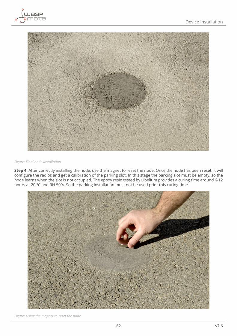
-62- v7.6
Device Installation
Figure: Final node installation
Step 4: After correctly installing the node, use the magnet to reset the node. Once the node has been reset, it will configure the radios and get a calibration of the parking slot. In this stage the parking slot must be empty, so the node learns when the slot is not occupied. The epoxy resin tested by Libelium provides a curing time around 6-12 hours at 20 ºC and RH 50%. So the parking installation must not be used prior this curing time.
Figure: Using the magnet to reset the node

-63- v7.6
Device Installation
Step 5: When the node gets the reference calibration, it will send several frames to the cloud: Start frame 1, Start frame 2 and Keep-Alive frame.
Figure: Start frames received in the Sigfox backend
11.5. Configuring the parking nodes in the callback serverCustomers have installed the callback server, as explained before. Now, all nodes have to be configured using the on-line form available.
Considering that a real deployment will have groups of nodes working with different configurations (for example, street #1, street #2), it is recommended that the final Remote Manager is able to generate the configuration depending on the group that each node belong to. This can be achieved if the cloud keeps record of the groups, and which nodes are inside each group.
Please, see the Sigfox and LoRaWAN sections to get more information about specific callback configuration.

-64- v7.6
Callback Services
12. Callback ServicesLibelium has implemented 3 callback services in the callback server application: Sigfox, Loriot and Actility. In this section, it is explained how to set them up with a simple configuration. If users want to use a service of other company not already implemented, we include in this section the instructions to develop that new service.
12.1. SigfoxThis section explains how to route the information received from the Sigfox platform to the callback server and generate the needed response.
12.1.1. Device configuration
Configure a new Group in the Sigfox back-end:
• 1. Display the parent group hitting on group top menu section. • 2. It is not allowed to create two same groups in the same level. An alert is shown while the form is saved
noticing the error. Skip to the Device Type creation step if the group already exists. • 3. Create the new group clicking in “New” button. Select the parent group following the next pop-up windows.
Finally, fill in the form with the information required, checking if the parent group written is the one chosen in the previous step.
Figure: Group creation schema

-65- v7.6
Callback Services
The next step is creating the Device Type in the back-end, clicking on “Device Type” in the top menu and then on “New” button.
Figure: Device type creation schema
A new pop-up window will be shown to select the group for the new Device Type, usually the group created previously.
Select the group and a new form will appear, provide all information required to create the Device Type. Sigfox nodes assigned to this Device type will share the same functionality. It is mandatory to select CALLBACK as Downlink mode.
Figure: Device type form
The next step is configuring the callback. Click on “Callbacks” option in the left menu and then create a new callback: “New” button in the window loaded.
Figure: Callback service creation

-66- v7.6
Callback Services
A new form will be displayed, please, fill in the form following the indications shown in the next image.
Figure: Callback form
Write the URL to access the Sigfox service endpoint in the field “Url pattern”. This URL has been previously configured in the callback server application hosted in your servers. Some extra variables have been added (to send to the service as much information as possible) following the information displayed in the form.
http://my_server.com/services/sigfox/?id={device}&time={time}&duplicate={duplicate}&snr={snr}&station={station}&data={data}&avgSnr={avgSnr}&lat={lat}&lng={lng}&rssi={rssi}&seq-Number={seqNumber}&ack=true
After the form is saved, the list of all available callbacks will be shown. Enable this entry with a downlink, the service running in your server will receive the information:
1. Activate “Downlink” column. There is a bullet in this column, and it must be activated. To activate, just click on it and leave the bullet coloured.
• Downlink active • Downlink inactive
2. “Enable” the callback. In the “Enable” column of the callback created, there is a check icon and you have to ensure that it is checked with a green colour.
• Callback enabled • Callback disabled
Figure: Callback list

-67- v7.6
Callback Services
Finally it is time for creating the device node itself, click on “Device” option in the top menu, wait for the next window to be loaded, click on “New” button.
Figure: Device creation
As it happened with the Device Type, the parent group of the device must be selected. Fill the following information in the new device form:
Figure: Device form
• Identifier: Device ID in hexadecimal format, given by the manufacturer. • Name: Device name. A descriptive name useful to identify your device easily. • PAC: Porting Authorization Code (PAC) is a unique hexadecimal number to identify the device regardless of
the network. This code is given by the device manufacturer. • Prototype: Mark this checkbox. • Product certificate: Leave blank. • Type: Select the device type created before. • Lat (-90º to +90º) / Lng (-180º to +180º) / Map: Grab the coordinates of your node to use these three fields. • Prevent token renewal?: Leave unchecked.

-68- v7.6
Callback Services
12.1.2. Server configuration
In the callback server previously installed, some parameters must be configured to enabe the communication with the node.
The services.ini file, located in data folder, has to be updated with the following information in the “sigfox” section.
[sigfox]log_level = “ALL”log_file = “../../logs/sigfox.log”
• log_level: This level is the minimum level to save logs in the system. Select among these levels: - OFF: This option deactivate the log. - ERROR : It only reports ERROR messages. - INFO: It reports ERROR + INFO messages. - DEBUG: it reports ERROR + INFO + DEBUG messages. - ALL: It reports everything happened in the process.
• log_file: The relative path where the log messages will be saved.

-69- v7.6
Callback Services
12.2. Loriot HTTPThis section explains how to route the information received from the Loriot platform to the callback server application using the protocol HTTP to generate a response if it is needed.
12.2.1. Device configuration
Log in and create a new application in the Loriot dashboard.
Figure: Creating an application
Click on “Devices” left menu to show the device list. Click on “Generate new device” button to add a new device. The new device will appear at the end of the list. Click on it to get more information.
Figure: Device creation schema
Data output section is the responsible to stablish the communication between the Loriot platform and the callback server application. Click on our application name in the left menu, the first right block “Network Application” contains the “Data output” option, the configuration is in the main window of the application created.
Figure: Output application selection

-70- v7.6
Callback Services
Click on “Edit output” to display all the information available about the selected output option. Click on “Change” button in the detailed window to change the data output, select “HTTP Push” of the multiple choices from the list.
Figure: Selecting the output application
Once selected the new output, a new section “Change output type” will be shown below, with a text field labelled as “Target URL for POSTs”. Write the URL of the callback background process for this service in the text field
http://my_server.com/services/loriot_http/

-71- v7.6
Callback Services
12.2.2. Server configuration
In the callback server previously installed, some parameters must be configured to enable the communication with the node.
The services.ini file, located in data folder, has to be updated with the following information in the loriot section.
[loriot_http]log_level = “ALL”log_file = “../../logs/loriot_http.log”server_url = “eu1.loriot.io”token = “xxxxxxxxxxxxxxxxxxxxxxxx”appid = “XXXXXXXX”
• log_level: This level is the minimum level to save logs in the system. Users can select one among these levels:
- OFF: This option deactivate the log. - ERROR : It only reports ERROR messages. - INFO: It reports ERROR + INFO messages. - DEBUG: it reports ERROR + INFO + DEBUG messages. - ALL: It reports everything happened in the process.
• log_file: The relative path where the log messages will be saved.
• server_url: The URL of the Loriot server. This usually is “eu1.loriot.io”, but it depends on your zone and the Loriot servers (“eu1.loriot.io” for Europe, “us1.loriot.io” for USA, “au1.loriot.io” for Australia…). If you can’t get the information using one of the previous mentioned, please contact with Loriot in order to know what the exact URL is.
• token: Token generated in the Loriot backend in order to be authorized to work with the platform. Click on “Security” menu from the left, and a list will be displayed with all tokens generated. To create a new one, just click on “Generate another authentication token” button, and a new record will be created in the table. Finally, copy the token hitting on “Show token” and paste the code in this parameter of the service configuration file.
Figure: Generating a token
• appid: Application ID assigned in the Loriot backend. This value is also displayed in the left menu, under the name of the application selected. Be careful because this parameter does not need hyphens in the service configuration file. Then, the format will be 8 characters (in the case of the following figure, the appid will be AABBCCDD).
Figure: Getting the application ID

-72- v7.6
Callback Services
12.3. Loriot websocketThis section explains how to route the information received from the Loriot platform to the callback server application and generate a response if it is needed.
12.3.1. Device configuration
Log in and create a new application in the Loriot dashboard.
Figure: Creating an application
Click on “Devices” on the left menu to show the device list. Click on “Generate new device” button to add a new device. The new device will appear at the end of the list. Click on it to get more information.
Figure: Device creation schema
Data output section is the responsible to stablish the communication between the platform and the callback server application. Click on our application name in the left menu, the first right block “Network Application” contains the “Data output” option, the configuration is in the main window of the application created.
Figure: Output application selection

-73- v7.6
Callback Services
Click on “Edit output” to display all the information available about the selected output option.Click on “Change” button in the detailed window to change the data output, select one of the multiple choices from the list.
Figure: Selecting the output application
“Websocket” is the method recommended to deliver the end-device data.
• It’s cloud-friendly (existing HTTP traffic optimization can be used) • It’s bi-directional, real-time interface • It’s easy to implement • It’s lower overhead compared to REST • It’s already supported in all major web browsers • It’s already supported in many programming languages
12.3.2. Server configuration
In the callback server previously installed, some parameters must be configured to enable the communication with the node.
The services.ini file, located in data folder, has to be updated with the following information in the loriot section.
[loriot]log_level = “ALL”log_file = “../../logs/loriot.log”websocket_url = “wss://eu1.loriot.io/app?id=xxxxxxx&token=xxx-xxxx”service_url = “http://my-server.com/services/loriot/”
• log_level: This level is the minimum level to save logs in the system. Select among these levels: - OFF: This option deactivate the log. - ERROR : It only reports ERROR messages. - INFO: It reports ERROR + INFO messages. - DEBUG: it reports ERROR + INFO + DEBUG messages. - ALL: It reports everything happened in the process.
• log_file: The relative path where the log messages will be saved. • websocket_url: The URL of the websocket listed in the Loriot dashboard. In the last window shown “Application
output”, in the second section “Current output setup” there are the target URL and the Authentication Token to access to the API interface.

-74- v7.6
Callback Services
Figure: Output setup
Clicking in “Authentication token” link, a new window will be shown with the tokens generated in the Loriot application.
To create a new one, just click on “Generate another authentication token” button, and a new record will be created in the table. Finally, copy the full URL hitting on “Show full URL” and paste the URL in this parameter of the service configuration file.
Figure: Generating an application token
• service_url: The URL to access to the Loriot service in your callback server previously configured. (http://my_server.com/services/loriot/)
12.3.3. Start the web-socket connection
This platform requires an additional step. Start the process which establish the connection to the Loriot server in order to receive and send information in all nodes.
Open a SSH connection to the web server in a terminal and navigate to the directory your_web_server_path/services/loriot. Execute following command to create the web-socket communication:
nohup nodejs websocket.js >>../../logs/loriot.log 2>&1 &
Kill this process to stop the web-socket communication.

-75- v7.6
Callback Services
12.4. ActilityThis section explains how to route the information received from the Actility platform to the callback server and generate a response if it is needed.
12.4.1. Device configuration
This service requires an Application Server and an AS routing profile in order to establish the communication with the callback server. These two elements are required before starting the service the first time, and will be the base to create devices.
Configure a new Application Server clicking on “Application Servers” on the left sidebar menu.
Figure: Application Servers menu
The first section allows you to create a new Application Server. Then the second section shows a list of all Application servers created. Click the “Add button” in the first section to create a new Application Server.
Figure: Application Servers

-76- v7.6
Callback Services
A name must be typed in the new window displayed. “HTTP Application Server” must be selected in type field. Click on the “Create” button to continue the process.
Figure: Application server name
In the new window, the name is copied from the previous pop-up, it is required to select “JSON” in the “Content Type” field. In the “Add a route” section, click on the “Add” button to create the link to the callback server installed.
Figure: Application server form
A “Route” section will be created above with a form, just click the “Add” button to proceed.
Figure: Route form

-77- v7.6
Callback Services
In the new pop-up, the URL to access the Actility service in your callback server previously configured has to be typed (http://my_server.com/services/actility/). Click on the “Add” button to save the information.
Figure: Destination form
Navigate back to the Application server form, click on “Save” in order to create the application server. Then, configure a new AS routing profile in the Device Manager clicking on “AS routing profiles” on the left sidebar menu.
Figure: AS Routing profiles menu
An “Add button” is shown in the first section. Below, in the second section, a list with all existing AS routing profiles will be displayed. New AS routing profile gives the capability to add new AS routing profiles. Clicking on the “Add” button to create a new AS Routing profile.
Figure: AS Routing profiles

-78- v7.6
Callback Services
A name must be typed in the new window displayed. Clicking on the “Create” button to continue the process.
Figure: AS Routing profile name
In the new window, mark the check “Is default” and click the “Add button” in the Add a route section.
Figure: AS Routing profile route
A new pop-up will appear with two parameters to be completed. “Type” is the kind of the application for our destination, “Local application server” must be selected. After that, in destination field, all the application servers created will be loaded in the drop-down. The application server previously created must be selected.
Figure: Add a route

-79- v7.6
Callback Services
Navigate back to the AS routing profile form, click on “Save” in order to create it.
This process should be completed once. From this moment, customers can add as many devices as they desire, clicking on the “Devices” option on the left menu, and then, in the new form loaded on the right frame, hit on the “Create” button.
Figure: Create a new device
A new form will be displayed in a new pop-up with the following information to be saved:
Figure: New device form

-80- v7.6
Callback Services
Administrative database
• Device name: Name to identify the device • Marker: Icon to identify the device on the map list • Administrative info: Relevant information of the device • Administrative location: Location of the device • Motion indicator: List with several options
Device identification
• Device activation: Select “Activation By Personalization (ABP)” • DevEUI: Device EUI, globally unique IEEE EUI-64 address • DevAddr: Device address • NwkSKey: Network Session Key, 128-bit key • Device profile: Select “LoRaWAN 1.0 - class A - ETSI - Rx2_SF12”
Network parameters
• Connectivity plan: Select a Connectivity plan on the drop-down menu. The displayed count indicates the remaining connectivity plans available.
Application layer handling
• Application server routing profile: Select the Application server created before. • AppSKeys: It is necessary to create a new AppSKey clicking on the “Add” button and a new register will be
displayed. AppSKey is a 128-bit key, and it must be available for all ports, leaving “*” in this field.
The last step is clicking the “Create” button in order to save the information of the device.
12.4.2. Server configuration
In the callback server previously installed, some parameters must be configured to enable the communication with the node.
The services.ini file, located in data folder, has to be updated with the following information in the actility section.
[actility]log_level = “ALL”log_file = “../../logs/actility.log”server_url = “https://api-dev1.thingpark.com/thingpark/lrc/rest/downlink”
• log_level: This level is the minimum level to save logs in the system. Users can select one among these levels: - OFF: This option deactivate the log. - ERROR : It only reports ERROR messages. - INFO: It reports ERROR + INFO messages. - DEBUG: it reports ERROR + INFO + DEBUG messages. - ALL: It reports everything happened in the process.
• log_file: The relative path where the log messages will be saved. • server_url: The downlink URL that Actility gives to send information from the server to the node. This URL is
the address of the primary Actility LRC cluster.

-81- v7.6
Callback Services
12.5. Saving the information receivedThis section explains how to get the information sent by the Smart Parking nodes to the callback server.
The services implemented by Libelium log the information in a file by default. To save the information in a database or a cloud service following files in charge of doing the operations described in the callback server need to be modified: • Sigfox: your_callback_server_path/services/sigfox/index.php • Loriot: your_callback_server_path/services/loriot/websocket_response.php • Actility: your_callback_server_path/services/actility/index.php
your_callback_server_path has to be replaced with the path where the callback server was previously installed. Search for a comment line like this in the previous source code files:
//To-Do: get the information received: $frame->get_data();
Example to save the information in a MySQL database using the PHP PDO library:$data = $frame->get_data();$link = new PDO(‘mysql:host=server;port=port;dbname=dbname;charset=utf8’, ‘user’, ‘pas-sword’);$statement = $link->prepare(“INSERT INTO table(field1, field2) VALUES(:data1, :data2)”);$statement->execute(array( “data1” => $data[‘parking’], “data2” => $data[‘battery’]));
It is recommended to paste this code block below the commented line.
Take a close look at the next section in order to get more information about all the data obtained using the get_data method.
12.6. How to develop a new serviceIt is possible to develop a new service different to the services provided by Libelium. The aim of a service is to get the payload sent from the Smart Parking nodes and generate the correct answer when it is needed. Both, the payload and the answer, have to be decoded according to Libelium specifications.
Each service can have its own functionality: some will require a websocket, some a URL to call, … The specifications of the new service should include all the information needed to implement the new service. We recommend to use PHP, so the new project could be developed faster reusing code created. The most useful PHP class is called frame, which has been created to simplify the payload-answer process and it is located in:your_callback_server_path/includes/class.Frame.php
“your_callback_server_path” has to be replaced with the path where the user has the callback server installed.
This is a complete description of all attributes and methods of the class frame:
Attributes
Name Descriptionprivate String data Information received from the node.private String type Frame type decoded from the information sent from the node.private String return String to return to the node.private String device_id Device ID of the node.private Array bytes Information received from the node converted into bytes.private Array bits Array in which each previous byte is converted into bits.private Array info Array with the information decoded.

-82- v7.6
Callback Services
Methods
Name Description
void __construct (String device_ID)Class constructor.Device ID has to be sent as a parameter. It will be saved in the attribute device_id.
void reset (void) Reset all attributes.
void get_info (String data)
Decode the information received from the node and store it in the attribute info.The information received from the node has to be sent as a parameter.The information decoded will be saved in the attribute info.
Boolean waiting_response(void) It returns a boolean to know if it necessary to send a response for the frame received.
String get_response(void) It returns a string to send to the node.Array get_data(void) It returns an array with all information decoded.
Using the get_data method of this class, users will get an array with the decoded information received from the node. Data will depend on the frame type received. These five parameters are common in all frame types:
Name Descriptiondevice_id ID of the device
battery Battery level. [0 = good charge level | 1 = little charge level]
parking Status of the parking slot [0 = empty | 1 = occupied]
frame_counter Counter of the frames received.
frame_type
Counter of the frames received. [0 = Info frame | 1 = Keep-Alive frame | 2 = Daily update frame | 3 = Error frame | 4 = Start frame 1 | 5 = Start frame 2]
And then, these are the parameters for each frame type:
Frame type 0 = Info frame
Name Descriptiontemperature_msb Raw temperature from the parking internal sensor.
To convert to Celsius degrees use the next formula:
Only available in firmware v1.x.x
temperature_lsb
temperatureTemperature (Celsius degrees) from the node’s internal sensor. The value of temperature is a signed integer. Only available from firmware v2.x.x
x_msbReference value from the sensor associated to the X axis.
x_lsby_msb
Reference value from the sensor associated to the Y axis. y_lsbz_msb
Reference value from the sensor associated to the Z axis. z_lsb

-83- v7.6
Callback Services
Frame type 1 = Keep-Alive frame
Name DescriptionNo data
Frame type 2 = Daily update frame
Name Descriptionsensor_msb
Times that the sensor is used in the las 24 hours.sensor_lsbsigfox_msb
Times that the Sigfox radio is used in the last 24 hours.sigfox_lsblorawan_msb
Times that the LoRaWAN radio is used in the last 24 hours.lorawan_lsb
resets_today Number of resets generated in the last 24 hours.CONFIG_ID Value of the configuration version loaded into the node.
This class will generate automatically the response for this frame type which is formed by 8 bytes with the following structure:
Byte bit 7 bit 6 bit 5 bit 4 bit 3 bit 2 bit 1 bit 00
Bytes reserved for the information saved in the configuration.ini file of the specific device
123456 Timestamp (hh) º hour with two numbers
7Enable daily
frameReset Timestamp (mm) º minutes with two numbers
Frame type 3 = Error frame
Name Description
error_z Error detected in the X axis of the sensor. [“1” = error | “” = no error]
error_y Error detected in the X axis of the sensor. [“1” = error | “” = no error]
error_x Error detected in the X axis of the sensor. [“1” = error | “” = no error]
error_rtc Error detected in the RTC (internal clock). [“1” = error | “” = no error]
error_lorawan Error detected in the LoRaWAN radio. [“1” = error | “” = no error]
error_sigfox Error detected in the Sigfox radio. [“1” = error | “” = no error]
temperature_msb Raw temperature from the parking internal sensor.To convert to Celsius degrees use the next formula:
Only available in firmware v1.x.x
temperature_lsb

-84- v7.6
Callback Services
temperature
Temperature (Celsius degrees) from the node’s internal sensor. The value of temperature is a signed integer.
Only available from firmware v2.x.xx_msb
Reference value from the sensor associated to the X axis.x_lsby_msb
Reference value from the sensor associated to the Y axis. y_lsbz_msb
Reference value from the sensor associated to the Z axis. z_lsb
battery_levelBattery voltage in millivolts. To convert to millivolts, use the next formula:
Frame type 4 = Start frame number 1
Name Descriptiontemperature_msb Raw temperature from the parking internal sensor.
To convert to Celsius degrees use the next formula:
Only available in firmware v1.x.x
temperature_lsb
temperatureTemperature (Celsius degrees) from the node’s internal sensor. The value of temperature is a signed integer. Only available from firmware v2.x.x
x_calibration_msbReference value from the sensor associated to the X axis.
x_calibration_lsby_calibration_msb
Reference value from the sensor associated to the Y axis. y_calibration_lsbz_calibration_msb
Reference value from the sensor associated to the Z axis.z_calibration_lsbbattery_level_msb
Battery voltage in millivolts.battery_level_lsb
This class will generate automatically the response for this frame type. It consists of 8 bytes with date and time information which will be sent to the node according to this structure:
Byte bit 7 bit 6 bit 5 bit 4 bit 3 bit 2 bit 1 bit 00 Timestamp (YY) º two last numbers of the year1 Timestamp (MM) º month with two numbers2 Timestamp (DD) º day with two numbers3 Timestamp (dow) º day of the week. 0 for Sunday, through 6 for Saturday.4 Timestamp (hh) º hour with two numbers5 Timestamp (mm) º minutes with two numbers67
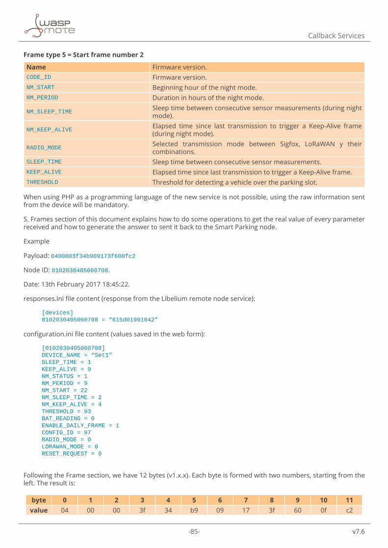
-85- v7.6
Callback Services
Frame type 5 = Start frame number 2
Name Firmware version.CODE_ID Firmware version.NM_START Beginning hour of the night mode.NM_PERIOD Duration in hours of the night mode.
NM_SLEEP_TIME Sleep time between consecutive sensor measurements (during night mode).
NM_KEEP_ALIVE Elapsed time since last transmission to trigger a Keep-Alive frame (during night mode).
RADIO_MODE Selected transmission mode between Sigfox, LoRaWAN y their combinations.
SLEEP_TIME Sleep time between consecutive sensor measurements.KEEP_ALIVE Elapsed time since last transmission to trigger a Keep-Alive frame.THRESHOLD Threshold for detecting a vehicle over the parking slot.
When using PHP as a programming language of the new service is not possible, using the raw information sent from the device will be mandatory.
S. Frames section of this document explains how to do some operations to get the real value of every parameter received and how to generate the answer to sent it back to the Smart Parking node.
Example
Payload: 0400003f34b909173f600fc2
Node ID: 0102030405060708.
Date: 13th February 2017 18:45:22.
responses.ini file content (response from the Libelium remote node service):
[devices]0102030405060708 = “615d01991642”
configuration.ini file content (values saved in the web form):
[0102030405060708]DEVICE_NAME = “Set1”SLEEP_TIME = 1KEEP_ALIVE = 9NM_STATUS = 1NM_PERIOD = 9NM_START = 22NM_SLEEP_TIME = 2NM_KEEP_ALIVE = 4THRESHOLD = 93BAT_READING = 0ENABLE_DAILY_FRAME = 1CONFIG_ID = 97RADIO_MODE = 0LORAWAN_MODE = 0RESET_REQUEST = 0
Following the Frame section, we have 12 bytes (v1.x.x). Each byte is formed with two numbers, starting from the left. The result is:
byte 0 1 2 3 4 5 6 7 8 9 10 11value 04 00 00 3f 34 b9 09 17 3f 60 0f c2

-86- v7.6
Callback Services
Byte 0 has always the same format in all frames and it is compulsory to start with it in order to know which frame type is.
byte 0
0 2 16
0 0 1 0 2
0 0 1 0 2
byte 7 6 5 4 3 2 1 0value 0 0 0 0 0 0 1 0
The information obtained in this step is:
• Parking slot (bit 7) 0 ® free • Battery state (bit 6) 0 ® normal • Frame type (bits 0-3) 0010 2 = 2 ® Frame type 2, daily update frame
Generate the answer according to the specifications explained in this section for this kind of frame. The first 6 bytes are for the value saved of this node from the responses.ini file (or from the request made to the Libelium remote node service explained in the section “How to create your own dashboard”). In this case, the value is 615d01991642. Then two bytes (6 and 7) have to be added following the instructions:
In byte 6, bits from 0 to 4 are booked for the hour of the current time, in this case, 18. The rest bits have no value. A conversion of the hour value to binary is needed to put all values according to the byte pattern: 1810 = 100102
byte 6
byte 7 6 5 4 3 2 1 0value 0 0 0 1 0 0 1 0
Convert the entire binary byte to hexadecimal format: 000100102 = 1216. And this is the result for byte 6.
In byte 7, bits from 0 to 5 are reserved for the minutes of the current time, in this case, 45. Then, bit 6 is the reset value and bit 7 is the enable daily frame value. These last two values are taken from the configuration.ini file, where all the dashboard parameters are saved. In this case, the values are 0 and 1 respectively.
Change the minute value to binary to generate this byte: 4510 = 1011012. Now it is time for filling bit 6 and 7 with their values: 101011012.
byte 7
byte 7 6 5 4 3 2 1 0value 1 0 1 0 1 1 0 1
A conversion from this binary value to hexadecimal format is needed to get byte 7: 101011012 = AD16
Finally, the last step is to join the results of the bytes 6 and 7 to the value of the configuration.ini file to send it to the node. The result of the whole process is: 615D0199164212AD.

-87- v7.6
Troubleshooting
13. Troubleshooting13.1. Windows does not recognize USB ports Sometimes it is possible that your computer does not recognize the USB port where the board is plugged. It is because you do not have installed the proper driver for the device, but do not worry, we will tell you how to fix this issue.
Firstly, it is necessary to open the Device Manager in order to see what device is not being detected. To open this window depends on the Windows version you have, but usually typing “Device Manager” in the Start > Search option it is enough.
Figure: Windows Device Manager
The devices that are not detected are always marked with an alert icon as the next image shows. Right-click and select the first choice, “Update Driver Software”.
Figure: Update driver

-88- v7.6
Troubleshooting
Then, the driver must be searched in the computer, in particular the same path where the Smart Devices App has been installed.
Figure: Search the driver in the computer
Once validated the path, the next pop-up will be displayed, noticing the driver is not verified. Users have to confirm clicking on “Install this driver software anyway”.
Figure: Security warning
After a while, the driver is installed.
Figure: Driver installed

-89- v7.6
Troubleshooting
But the process is not finished. The first driver installed is “USB Serial Converter” but it is necessary to check the Device Manager list to verify the status. If the warning remains near the USB serial port, users have to repeat the “Update driver software” process again.
Figure: USB devices to verify
When the process is finished, users can check both drivers have been installed.
Figure: USB devices with all drivers installed
Now, the Smart Device App is ready to detect the ports and make the operation you want to do.

-90- v7.6
Troubleshooting
13.2. How to know the port where the device is plugged inUsers have to select in the Smart Devices App the port assigned to the Smart Parking node in the computers to make any operation with the Smart Parking node.
The assigned port depends on the USB devices that the users have plugged in their computers. The port displayed in the images of this guide may not correspond with the users port.
Follow these steps to discover the Smart Parking node port:
Step 1: Unplug the Smart Parking device from the computer and refresh the list. Take a look of all ports detected.
Figure: Port list without the node connected
Step 2: Plug the Smart Parking device and refresh the list again.
Figure: Port list with the node connected
Step 3: Compare the results with the previous ones and the new port detected is the Smart Parking node plugged in the last step.
Figure: Comparing the results
13.3. I cannot load nor save the configuration in the nodeSometimes users can experience that they cannot do any operation with the node in the Smart Devices App.
Figure: Error messages displayed in load / save operation
A message like one of the previous can be displayed. When the USB port is properly selected, the problem could be that the Smart Parking node has gone to deepsleep state. To solve it, power off the node and then power it on again. Then, click on “load” or “save” button as soon as possible, just before the node enter in deepsleep state (it takes 4 or 5 seconds).

-91- v7.6
Documentation changelog
14. Documentation changelog
From v7.5 to v7.6
• Added references to the 4th version of Smart Parking: Smart Parking for India • Added LoRaWAN IN865-867 frequency plan references
From v7.4 to v7.5 • Added references to the 3rd version of Smart Parking: Smart Parking for APAC / LATAM • Added LoRaWAN AU915 frequency plan references • Updated Sigfox zones information according to Sigfox website
From v7.3 to v7.4 • Added new firmware v3.x.x frames explanation • Added indications for placing the nodes under the ground for special deployments • Changed “Plug and Sense! Smart Parking” product references to “Smart Parking” • Added information about region standards • Updated “Certifications” section
From v7.2 to v7.3 • Modified “Actility” section, adapting it to the Actility new cloud version
From v7.1 to v7.2 • Added “Upgrading” in “Smart Devices App” section • Modified images of “Smart Devices App” • Added “Upgrading” in “Callback Server” section • Modified images of “Web form” • Modified API in “Callback Service” • Modified how to get the device IDs of your nodes from the services backends • Added “Loriot HTTP” service • Renamed “Loriot” to “Loriot Websocket” • Added indications related to the new firmware v2.1.0
From v7.0 to v7.1: • Added “How to close the Smart Parking enclosure to keep the waterproof IP68 feature” section • Added setting anchors instructions • Added IP68 feature • Added new frame explanation for firmware version v2.x.x • Added countries compatibility table for LoRaWAN • Added battery type and capacity • Modified the LEDs on sequence • Added “How to create your own remote node configuration panel” section • Added “Services” section which includes Sigfox, Loriot and Actility • Added “Saving the information received” section • Added “How to develop a new service” section
From v4.0 to v7.0: • Modified “Sigfox” section • Added “Loriot” section

-92- v7.6
Documentation changelog
• Added “Actility” section • Added “Developing the network” section • Modified “Configuring the parking nodes from the cloud” section

-93- v7.6
Certifications
15. CertificationsLibelium offers 2 types of IoT sensor platforms, Waspmote OEM and Plug & Sense!:
• Waspmote OEM is intended to be used for research purposes or as part of a major product so it needs final certification on the client side. More info at: www.libelium.com/products/waspmote
• Plug & Sense! is the line ready to be used out-of-the-box. It includes market certifications. See below the specific list of regulations passed. More info at: www.libelium.com/products/plug-sense
CE
In accordance with the R&TTE Directive (1999/5/EC) and the 2002/95/CE Directive, Libelium Comunicaciones Distribuidas S.L. declares that the “Smart Parking EU” device conforms to the following regulations:
• EN 50581 (2012) • EN 301 489-1 v1.9.2 (2011) • EN 301 489-3 v1.6.1 (2013) • EN 300 220-1 v.2.3.1 (2010) • EN 300 220-2 v.2.3.1 (2010) • EN 300 220-1 v.2.4.1 (2012-05) • EN 300 220-2 v.2.4.1 (2012-05) • EN 60950-1 (2006) / A11 (2009) / A1 (2010) / A12 (2011) / Ac (2011) / A2 (2013) (except annex Zx)
FCC
“Smart Parking US” is ready for US. It has been certified under the Part 15 Spread Spectrum Transmitter (FCC Rule Part 15 C). If you want to know more contact the Libelium Sales Department.

-94- v7.6
Disposal and recycling
16. Disposal and recyclingIn this section, the term “Waspmote” encompasses both the Waspmote device itself as well as it enclosure.
When Waspmote reaches the end of its useful life, it must be taken to an electronic equipment recycling point.
The equipment must be disposed of in a selective waste collection system, and not that for urban solid residue. Please manage its disposal properly.
Your distributor will inform you about the most appropriate and environmentally friendly disposal process for the used product and its packaging.

-95- v7.6