smart metering requirements - massachusetts
TRANSCRIPT
Creating A Clean, Affordable, and Resilient Energy Future For the Commonwealth
COMMONWEALTH OF MASSACHUSETTSCharles D. Baker, Governor
Karyn E. Polito, Lt. GovernorMatthew A. Beaton, Secretary
Judith F. Judson, Commissioner
SMART Metering Requirements
October 11, 2019

Key Differences Between SREC II and SMART
• EDCs will own production meters and will be responsible for collecting data and reporting to NEPOOL GIS (no more PTS reporting requirements)
➢Owner of PV system responsible for paying for meter via the interconnection process
➢ Installers must leave open socket for utility owned production meter when designing systems
• EDCs own all Renewable Energy Certificates (RECs) for the duration of the tariff term
➢Customer must sign a REC assignment form acknowledging the EDCs ownership of the RECs before enrolling in tariff
2

SMART Program Participant Meter Costs
3
• SMART Production Meter(s)➢ Paid for during interconnection application
o Process may be slightly different for early stage program applicants that already went through the interconnection process before the start of the program
➢ Total meter costs paid for by interconnecting customer➢ May be multiple meters if paired with energy storage depending on
configuration➢ Metering requirements will vary by utility

4
SMART Program SpecificMetering Wiring Diagrams
October 2019
5
Interconnection ProcessRemaining the Same
• Requests for meters are made to the DG Interconnections team
• Eversource will install and support all Revenue and Production meters
• Eversource will provide a PTO upon successful connection
Changes for the SMART Program
• Requirement page (4) was split in two and the IC responsibility to turn on the disconnect
switch when the PTO is issued was outlined and highlighted.
• DG will ask for your SMART Application ID upfront
• This requires the submittal of the SMART Application via the Web Portal prior to
contacting the DG Interconnections team
• For Behind the Meter Installations (BTM)
• Customer will be charged the cost of BTM Production Meter and installation fees upon
submission of the SMART Application Fee via the Web Portal• Note: for larger, complex systems (additional charges still apply from ES engineering, i.e.,
CTs’, PT’s, etc.)
• Will require customer-installed wiring, and installation of a second meter socket
• Must be adequately accessible, proximate to existing utility revenue meter

6
Meter Configurations
Service Type Project size Meter Type
120/240V Single Phase 3 - wire Under 60KW Form 2S Bridge
120/208V Single Phase 3 - wire Under 60KW Form 12S Bridge
120/208V Three Phase 4-wire Under 60KW Form 16S Bridge
277/480V Three Phase 4-wire Under 60KW Form 16S Bridge
120/240V Single Phase 3 - wire Over 60KW Form 2S Interval
120/208V Single Phase 3 - wire Over 60KW Form 12S Interval
120/208V Three Phase 4-wire Over 60 KW Form 16S Interval
277/480V Three Phase 4-wire Over 60KW Form 16S Interval
IT Rated Single Phase (secondary CTs) Over 320A Form 4S Interval
IT Rated Three Phase (secondary CTs/PTs) Over 320A Form 9S Interval
IT Rated Single Phase (primary CTs) Over 320A Form 4S Interval
IT Rated Three Phase (primary CTs/PTs) Over 320A Form 9S Interval
7
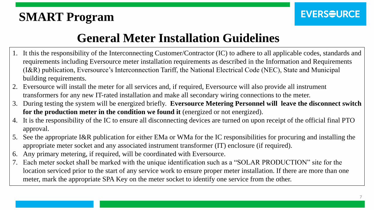
SMART Program
General Meter Installation Guidelines1. It this the responsibility of the Interconnecting Customer/Contractor (IC) to adhere to all applicable codes, standards and
requirements including Eversource meter installation requirements as described in the Information and Requirements
(I&R) publication, Eversource’s Interconnection Tariff, the National Electrical Code (NEC), State and Municipal
building requirements.
2. Eversource will install the meter for all services and, if required, Eversource will also provide all instrument
transformers for any new IT-rated installation and make all secondary wiring connections to the meter.
3. During testing the system will be energized briefly. Eversource Metering Personnel will leave the disconnect switch
for the production meter in the condition we found it (energized or not energized).
4. It is the responsibility of the IC to ensure all disconnecting devices are turned on upon receipt of the official final PTO
approval.
5. See the appropriate I&R publication for either EMa or WMa for the IC responsibilities for procuring and installing the
appropriate meter socket and any associated instrument transformer (IT) enclosure (if required).
6. Any primary metering, if required, will be coordinated with Eversource.
7. Each meter socket shall be marked with the unique identification such as a “SOLAR PRODUCTION” site for the
location serviced prior to the start of any service work to ensure proper meter installation. If there are more than one
meter, mark the appropriate SPA Key on the meter socket to identify one service from the other.
8
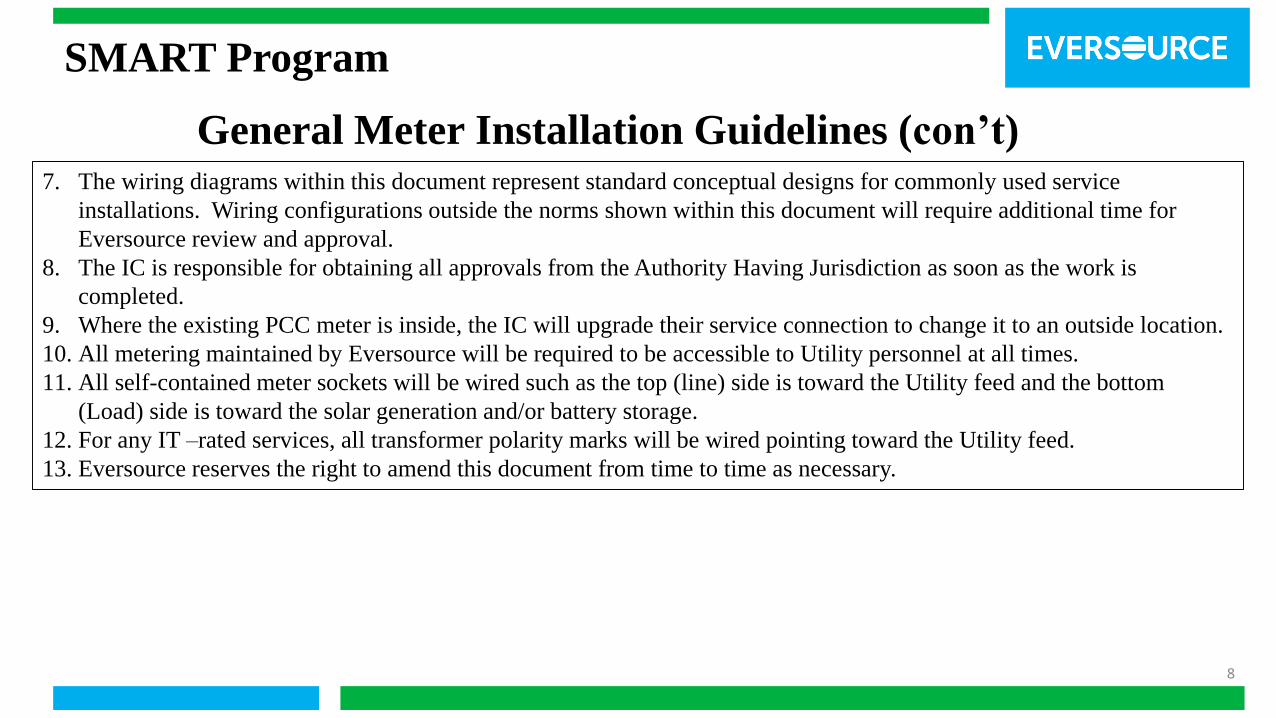
SMART Program
General Meter Installation Guidelines (con’t)7. The wiring diagrams within this document represent standard conceptual designs for commonly used service
installations. Wiring configurations outside the norms shown within this document will require additional time for
Eversource review and approval.
8. The IC is responsible for obtaining all approvals from the Authority Having Jurisdiction as soon as the work is
completed.
9. Where the existing PCC meter is inside, the IC will upgrade their service connection to change it to an outside location.
10. All metering maintained by Eversource will be required to be accessible to Utility personnel at all times.
11. All self-contained meter sockets will be wired such as the top (line) side is toward the Utility feed and the bottom
(Load) side is toward the solar generation and/or battery storage.
12. For any IT –rated services, all transformer polarity marks will be wired pointing toward the Utility feed.
13. Eversource reserves the right to amend this document from time to time as necessary.

9
SMART Program
Metering Diagrams
Metering Notes:
• BTM: Behind the Meter installation option
• DER: Distributed Energy Resource
• DG: Distributed Generator/Solar Array
• ESS: Energy Storage System
• EPS: Electric Power System
• IC: Interconnecting Customer
• PCC: Point of Common Coupling
• PoC: Point of Connection
• PTO: Permission to Operate
• SPAKey: Smart Program Account number
10
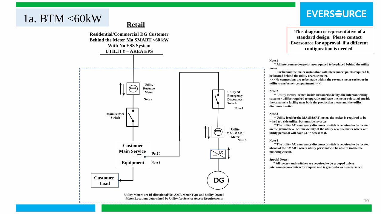
1a. BTM <60kWThis diagram is representative of a
standard design. Please contact
Eversource for approval, if a different
configuration is needed.
Note 1
* All interconnection point are required to be placed behind the utility
meter
For behind the meter installations all interconnect points required to
be located behind the utility revenue meter.
>>> No connections are to be made within the revenue meter socket or in
utility transformer compartment. <<<
Note 2
* Utility meters located inside customers facility, the interconnecting
customer will be required to upgrade and have the meter relocated outside
the customers facility near both the production meter and the utility
disconnect switch.
Note 3
* Utility feed for the MA SMART meter, the socket is required to be
wired top side utility, bottom side inverter.
* The utility AC emergency disconnect switch is required to be located
on the ground level within vicinity of the utility revenue meter where our
utility personal will have 24 / 7 access to it.
Note 4
* The utility AC emergency disconnect switch is required to be located
ahead of the SMART where utility personal will be able to isolate the
metering circuit.
Special Notes:
* All meters and switches are required to be grouped unless
interconnection contractor request and is granted a written variance.
Retail
Residential/Commercial DG Customer
Behind the Meter Ma SMART <60 kW
With No ESS System
UTILITY – AREA EPS
Customer
Load
Utility
MA SMART
Meter
Customer
Main Service
Equipment
Utility
Revenue
Meter Utility AC
Emergency
Disconnect
Switch
PoC
DG
Utility Meters are Bi-directional/Net AMR Meter Type and Utility Owned
Meter Locations determined by Utility for Service Access Requirements
Note 1
Note 2
S
Note 3
Note 4
Main Service
Switch
11
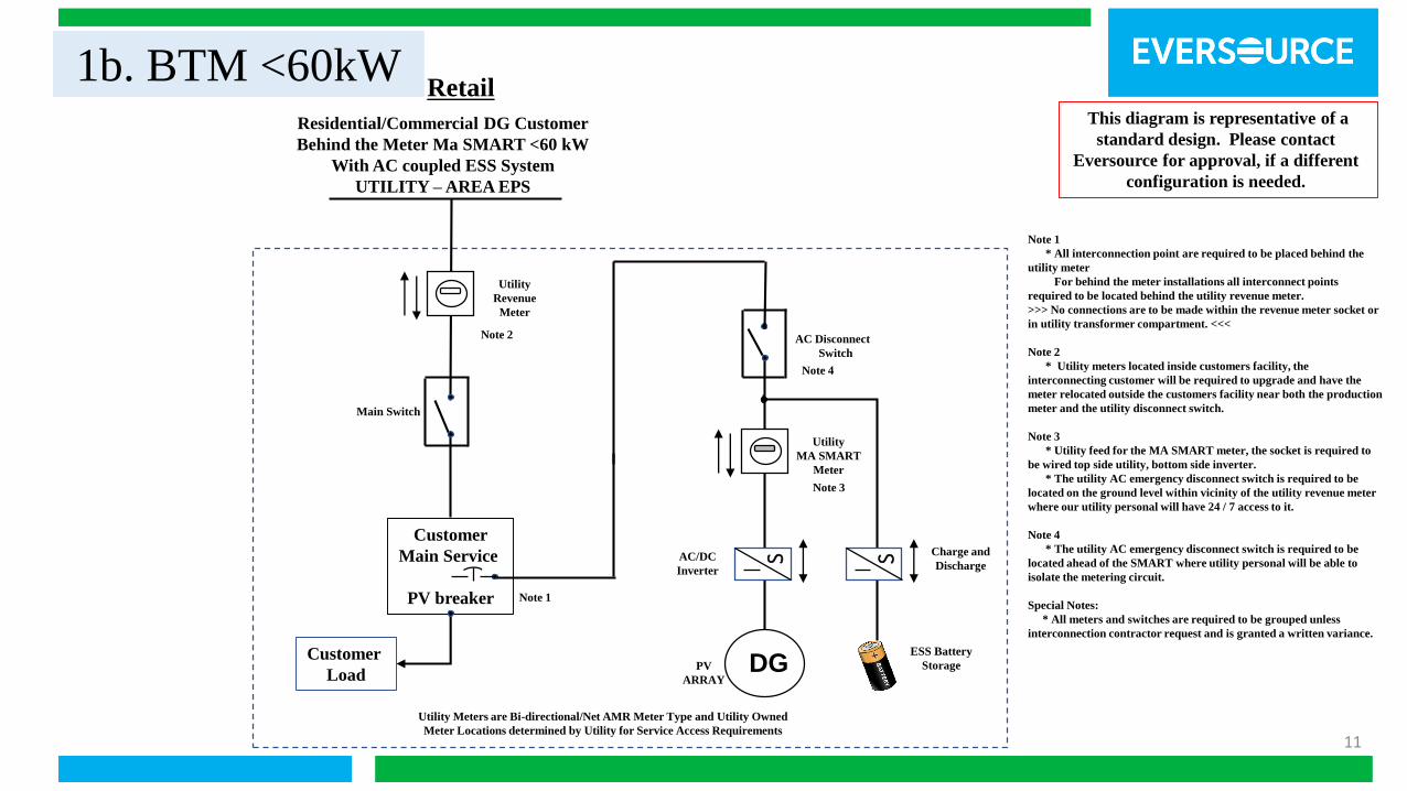
1b. BTM <60kWRetail
Residential/Commercial DG Customer
Behind the Meter Ma SMART <60 kW
With AC coupled ESS System
UTILITY – AREA EPS
Customer
Load
Utility
MA SMART
Meter
Customer
Main Service
PV breaker
Utility
Revenue
Meter
DG
Utility Meters are Bi-directional/Net AMR Meter Type and Utility Owned
Meter Locations determined by Utility for Service Access Requirements
Note 1
Charge and
Discharge
Note 2
ESS Battery
Storage
Note 1
* All interconnection point are required to be placed behind the
utility meter
For behind the meter installations all interconnect points
required to be located behind the utility revenue meter.
>>> No connections are to be made within the revenue meter socket or
in utility transformer compartment. <<<
Note 2
* Utility meters located inside customers facility, the
interconnecting customer will be required to upgrade and have the
meter relocated outside the customers facility near both the production
meter and the utility disconnect switch.
Note 3
* Utility feed for the MA SMART meter, the socket is required to
be wired top side utility, bottom side inverter.
* The utility AC emergency disconnect switch is required to be
located on the ground level within vicinity of the utility revenue meter
where our utility personal will have 24 / 7 access to it.
Note 4
* The utility AC emergency disconnect switch is required to be
located ahead of the SMART where utility personal will be able to
isolate the metering circuit.
Special Notes:
* All meters and switches are required to be grouped unless
interconnection contractor request and is granted a written variance.
This diagram is representative of a
standard design. Please contact
Eversource for approval, if a different
configuration is needed.
S SAC/DC
Inverter
PV
ARRAY
Note 3
Note 4
AC Disconnect
Switch
Main Switch
12
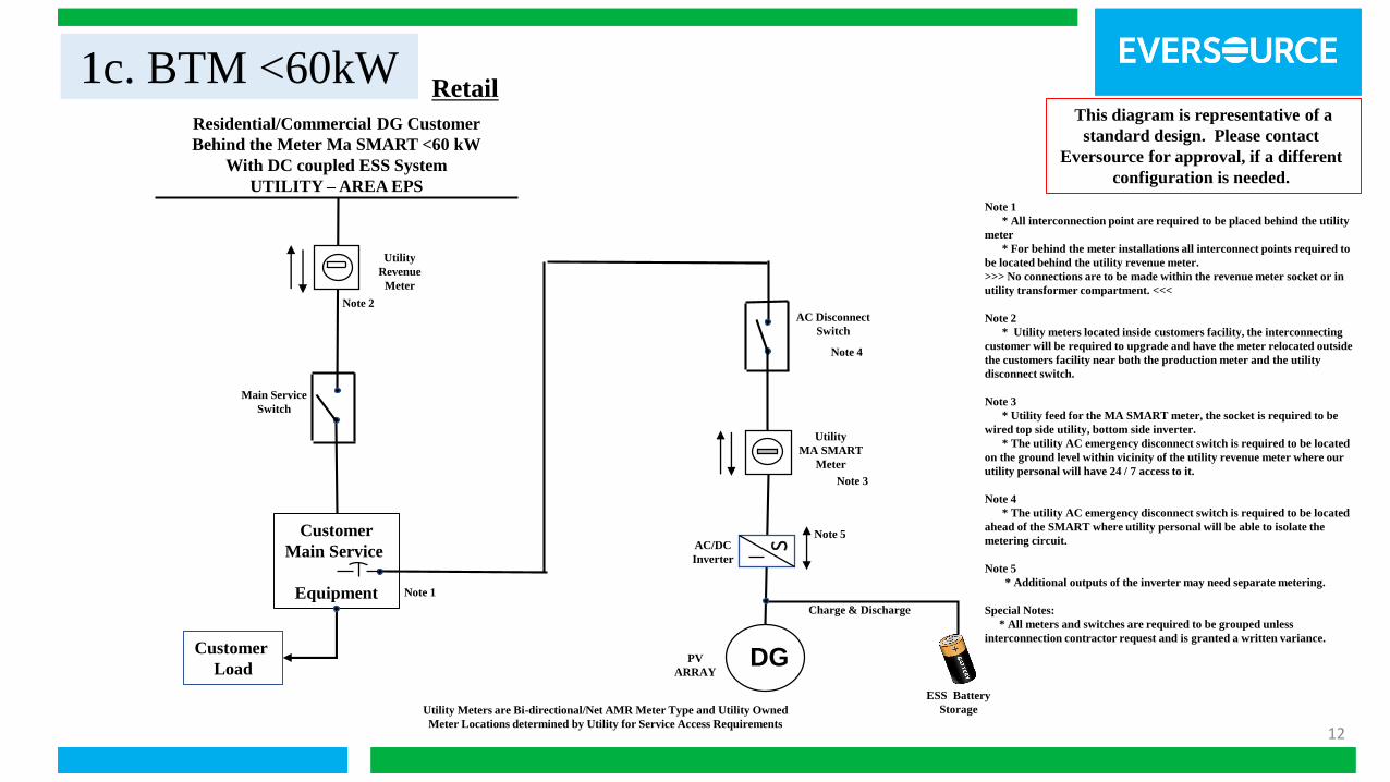
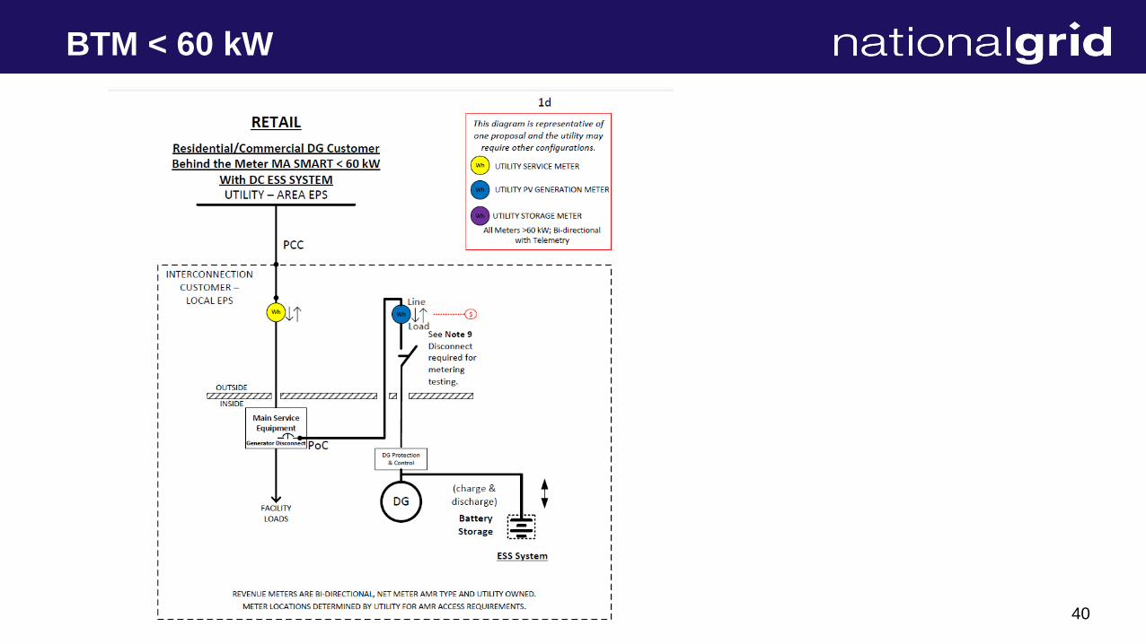
1c. BTM <60kWRetail
Residential/Commercial DG Customer
Behind the Meter Ma SMART <60 kW
With DC coupled ESS System
UTILITY – AREA EPS
Customer
Load
Utility
MA SMART
Meter
Customer
Main Service
Equipment
Utility
Revenue
Meter
DG
Utility Meters are Bi-directional/Net AMR Meter Type and Utility Owned
Meter Locations determined by Utility for Service Access Requirements
Note 1
ESS Battery
Storage
Charge & Discharge
Note 2
Note 1
* All interconnection point are required to be placed behind the utility
meter
* For behind the meter installations all interconnect points required to
be located behind the utility revenue meter.
>>> No connections are to be made within the revenue meter socket or in
utility transformer compartment. <<<
Note 2
* Utility meters located inside customers facility, the interconnecting
customer will be required to upgrade and have the meter relocated outside
the customers facility near both the production meter and the utility
disconnect switch.
Note 3
* Utility feed for the MA SMART meter, the socket is required to be
wired top side utility, bottom side inverter.
* The utility AC emergency disconnect switch is required to be located
on the ground level within vicinity of the utility revenue meter where our
utility personal will have 24 / 7 access to it.
Note 4
* The utility AC emergency disconnect switch is required to be located
ahead of the SMART where utility personal will be able to isolate the
metering circuit.
Note 5
* Additional outputs of the inverter may need separate metering.
Special Notes:
* All meters and switches are required to be grouped unless
interconnection contractor request and is granted a written variance.
This diagram is representative of a
standard design. Please contact
Eversource for approval, if a different
configuration is needed.
SAC/DC
Inverter
PV
ARRAY
Note 3
Note 4
AC Disconnect
Switch
Main Service
Switch
Note 5
13
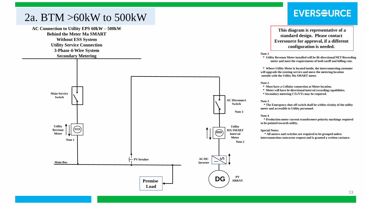
2a. BTM >60kW to 500kW
Note 1
* Utility Revenue Meter installed will be Bi-directional/NET/Recording
meter and meet the requirements of both tariff and billing rate.
* Where Utility Meter is located inside, the interconnecting customer
will upgrade the existing service and move the metering location
outside with the Utility Ma SMART meter.
Note 2
* Must have a Cellular connection at Meter location.
* Meter will have bi-directional interval recording capabilities.
* Secondary metering CTs/VTs may be required.
Note 3
* The Emergency shut off switch shall be within vicinity of the utility
meter and accessible to Utility personnel.
Note 4
* Production meter current transformers polarity markings required
to be pointed towards utility.
Special Notes:
* All meters and switches are required to be grouped unless
interconnection contractor request and is granted a written variance.
AC Connection to Utility EPS 60kW – 500kW
Behind the Meter Ma SMART
Without ESS System
Utility Service Connection
3-Phase 4-Wire System
Secondary Metering
Premise
Load
Utility
MA SMART
Interval
Meter
Utility
Revenue
Meter
DG
SPV breaker AC/DC
Inverter
Note 1Note 2
This diagram is representative of a
standard design. Please contact
Eversource for approval, if a different
configuration is needed.
PV
ARRAY
Note 3
Main Service
SwitchAC Disconnect
Switch
Main Bus

14
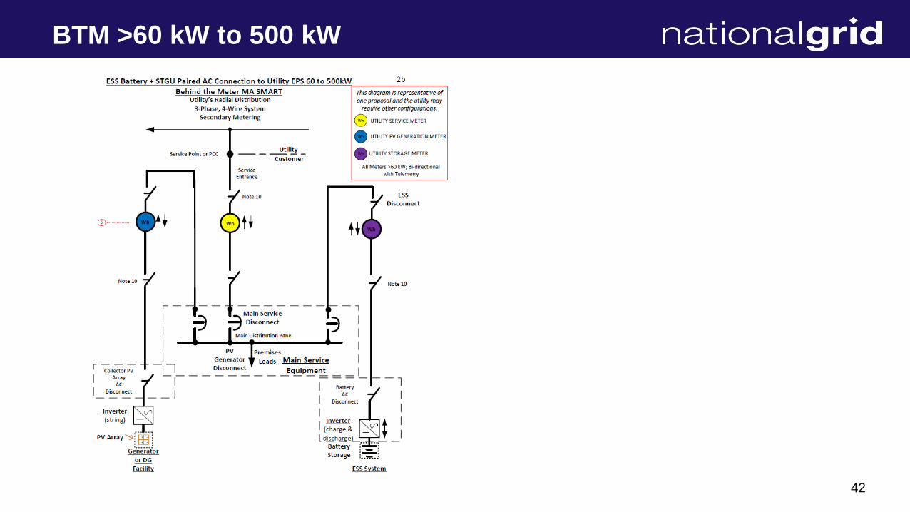
2b. BTM >60kW to 500kWAC Connection to Utility EPS 60kW – 500kW
Behind the Meter Ma SMART
With AC coupled ESS System
Utility Service Connection
3-Phase 4-Wire System
Secondary Metering
Premise
Load
Utility
Revenue
Meter
Main Service
Switch
Note 1
ESS Battery
Storage
S
DG
SInverter
PV Array
Utility
MA SMART
Interval
Meter
Note 2
Note 1
* Utility Revenue Meter installed will be Bi-directional/NET/Recording
meter and meet the requirements of both tariff and billing rate.
* Where Utility Meter is located inside, the interconnecting customer will
and upgrade the existing service to move the metering location outside
with the Utility Ma SMART meter.
Note 2
* Must have a Cellular connection at Meter location.
* Meter will have bi-directional interval recording capabilities.
* Secondary metering CTs/VTs may be required.
Note 3
* The Emergency shut off switch shall be located within the vicinity of the
Revenue meter and fully accessible to Utility personnel.
This diagram is representative of a
standard design. Please contact
Eversource for approval, if a different
configuration is needed.
Note 3
AC Disconnect
Switch
InverterMain Bus
15
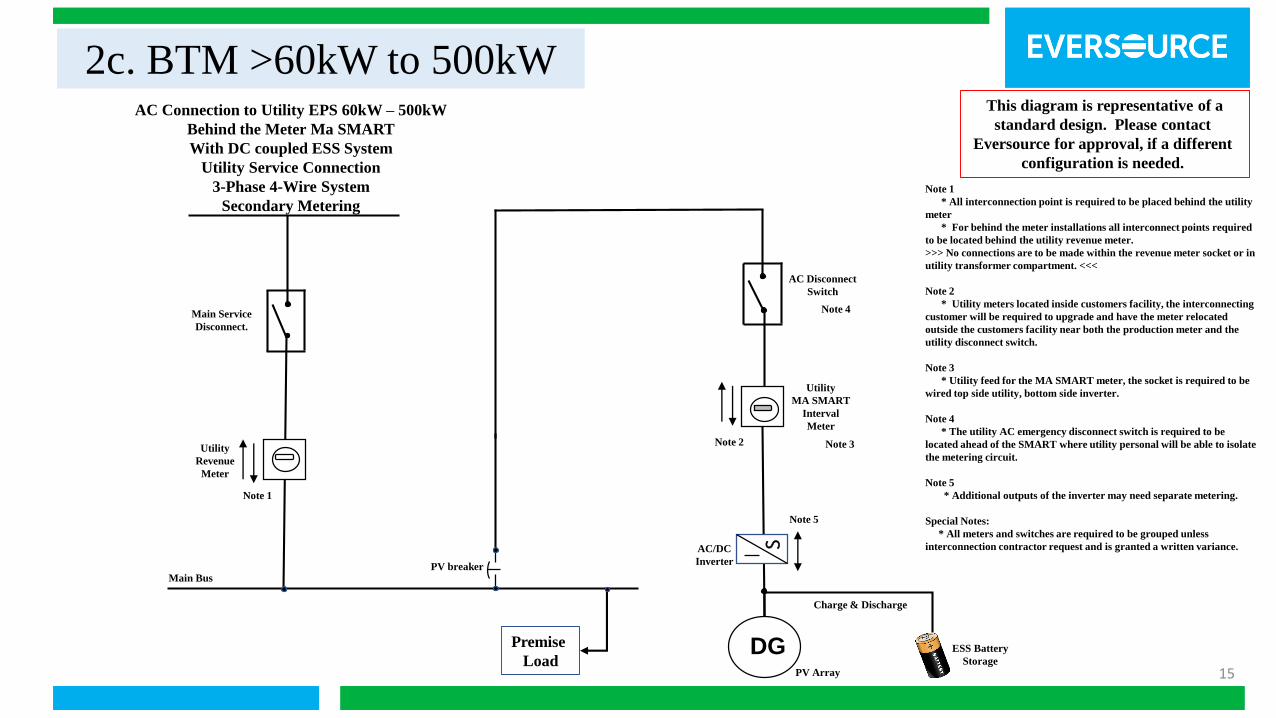
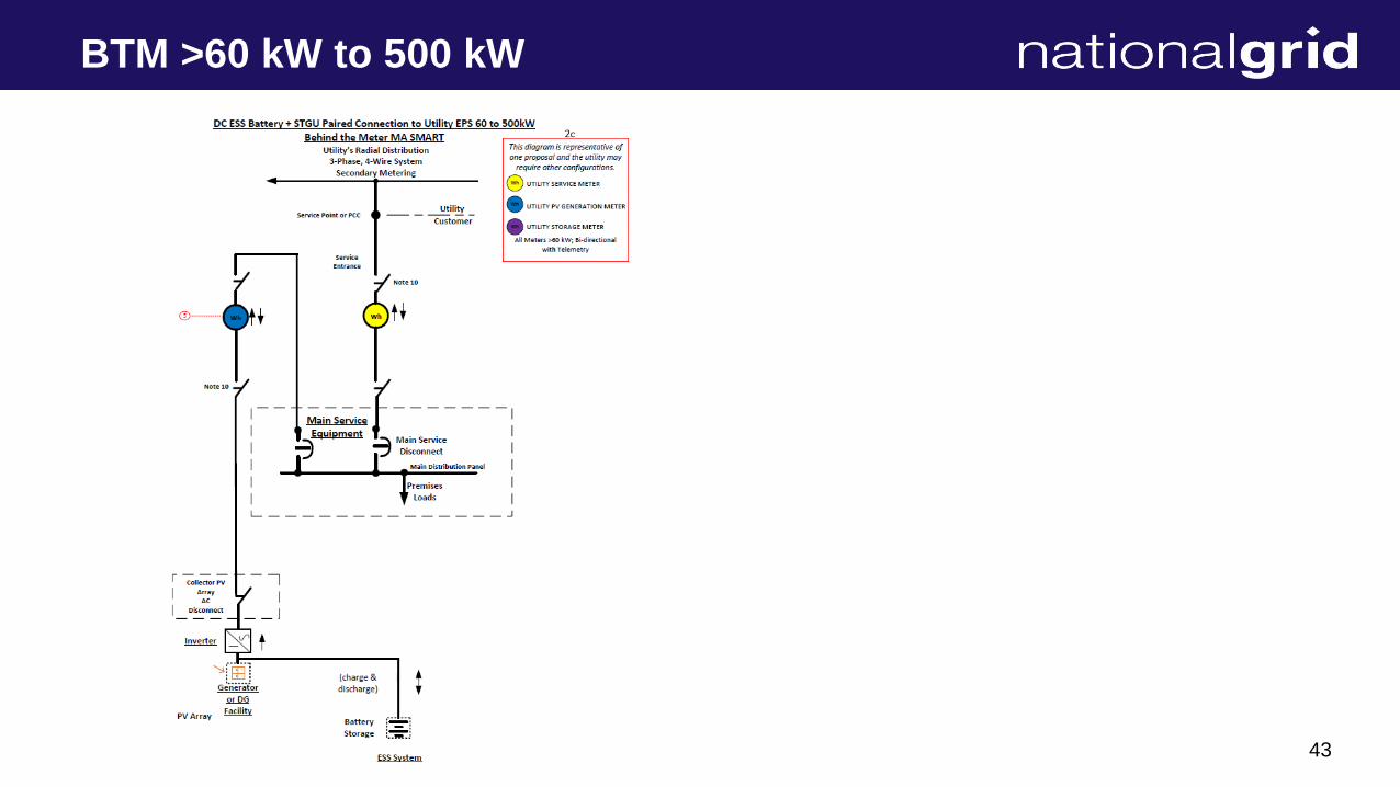
2c. BTM >60kW to 500kW
ESS Battery
Storage
AC Connection to Utility EPS 60kW – 500kW
Behind the Meter Ma SMART
With DC coupled ESS System
Utility Service Connection
3-Phase 4-Wire System
Secondary Metering
Premise
Load
Utility
Revenue
Meter
PV breaker
Main Service
Disconnect.
Note 1
Utility
MA SMART
Interval
Meter
DG
SAC/DC
Inverter
PV Array
Note 2
Charge & Discharge
Note 1
* All interconnection point is required to be placed behind the utility
meter
* For behind the meter installations all interconnect points required
to be located behind the utility revenue meter.
>>> No connections are to be made within the revenue meter socket or in
utility transformer compartment. <<<
Note 2
* Utility meters located inside customers facility, the interconnecting
customer will be required to upgrade and have the meter relocated
outside the customers facility near both the production meter and the
utility disconnect switch.
Note 3
* Utility feed for the MA SMART meter, the socket is required to be
wired top side utility, bottom side inverter.
Note 4
* The utility AC emergency disconnect switch is required to be
located ahead of the SMART where utility personal will be able to isolate
the metering circuit.
Note 5
* Additional outputs of the inverter may need separate metering.
Special Notes:
* All meters and switches are required to be grouped unless
interconnection contractor request and is granted a written variance.
This diagram is representative of a
standard design. Please contact
Eversource for approval, if a different
configuration is needed.
Note 3
Note 4
AC Disconnect
Switch
Main Bus
Note 5
16
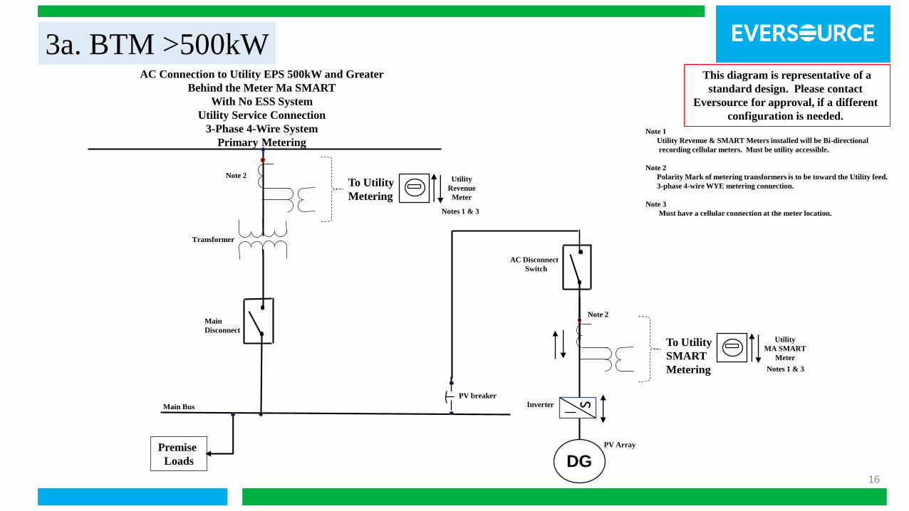
3a. BTM >500kW
Note 1
Utility Revenue & SMART Meters installed will be Bi-directional
recording cellular meters. Must be utility accessible.
Note 2
Polarity Mark of metering transformers is to be toward the Utility feed.
3-phase 4-wire WYE metering connection.
Note 3
Must have a cellular connection at the meter location.
AC Connection to Utility EPS 500kW and Greater
Behind the Meter Ma SMART
With No ESS System
Utility Service Connection
3-Phase 4-Wire System
Primary Metering
Premise
Loads
Main Bus SInverter
DGPV Array
Utility
Revenue
Meter
Notes 1 & 3
To Utility
Metering
Main
Disconnect
Utility
MA SMART
Meter
To Utility
SMART
Metering
Note 2
Note 2
Notes 1 & 3
This diagram is representative of a
standard design. Please contact
Eversource for approval, if a different
configuration is needed.
AC Disconnect
Switch
Transformer
PV breaker
17
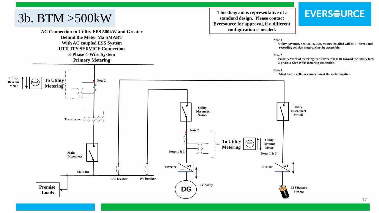
3b. BTM >500kW3b. BTM >500kWAC Connection to Utility EPS 500kW and Greater
Behind the Meter Ma SMART
With AC coupled ESS System
UTILITY SERVICE Connection
3-Phase 4-Wire System
Primary Metering
Premise
Loads
Main Bus
Notes 1 & 3Main
Disconnect
DGSInverter
PV Array
SInverter
ESS Battery
Storage
Note 1
Utility Revenue, SMART & ESS meters installed will be Bi-directional
recording cellular meters. Must be accessible.
Note 2
Polarity Mark of metering transformers is to be toward the Utility feed.
3-phase 4-wire WYE metering connection.
Note 3
Must have a cellular connection at the meter location.
This diagram is representative of a
standard design. Please contact
Eversource for approval, if a different
configuration is needed.
Utility
Revenue
Meter
To Utility
Metering
Note 2
Utility
Revenue
Meter
Notes 1 & 3
To Utility
Metering
Utility
Disconnect
Switch
Transformer
PV breakerESS breaker
Utility
Disconnect
Switch
Note 2

18
3c. BTM >500kWAC Connection to Utility EPS 500kW and Greater
Behind the Meter Ma SMART
With DC coupled ESS System
UTILITY SERVICE Connection
3-Phase 4-Wire System
Primary Metering
Premise
Loads
PV / ESS
breaker
Main Bus
Main Disconnect
Utility
MA SMART
Meter
To Utility
SMART
Metering
DG
Inverter
PV Array
Note 2
ESS Battery
Storage
Note 1
Utility Revenue & SMART Meters installed will be Bi-directional
recording cellular meters. Must be accessible.
Note 2
Polarity Mark of metering transformers is to be toward the Utility feed.
3-phase 4-wire WYE metering connection.
Note 3
Must have a cellular connection at the meter location.
Note 4
* Additional outputs of the inverter may need separate metering.
Notes 1 & 3
This diagram is representative of a
standard design. Please contact
Eversource for approval, if a different
configuration is needed.
Utility
Revenue
Meter
To Utility
Metering
Note 2
S
Transformer
Utility
Disconnect
Switch
Note 4

19
Stand-Alone Wiring Diagrams
20
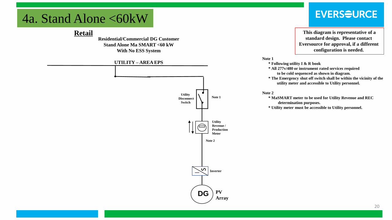
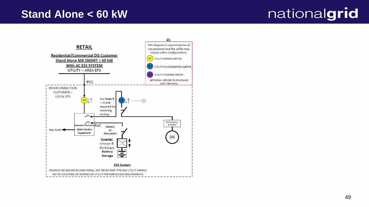
4a. Stand Alone <60kWRetail
Residential/Commercial DG Customer
Stand Alone Ma SMART <60 kW
With No ESS System
UTILITY –AREA EPS
This diagram is representative of a
standard design. Please contact
Eversource for approval, if a different
configuration is needed.
DG PV
ArrayS Inverter
Note 1
Utility
Revenue /
Production
Meter
Utility
Disconnect
Switch
Note 2
Note 1
* Following utility I & R book
* All 277v/480 or instrument rated services required
to be cold sequenced as shown in diagram.
* The Emergency shut off switch shall be within the vicinity of the
utility meter and accessible to Utility personnel.
Note 2
* MaSMART meter to be used for Utility Revenue and REC
determination purposes.
* Utility meter must be accessible to Utility personnel.
21
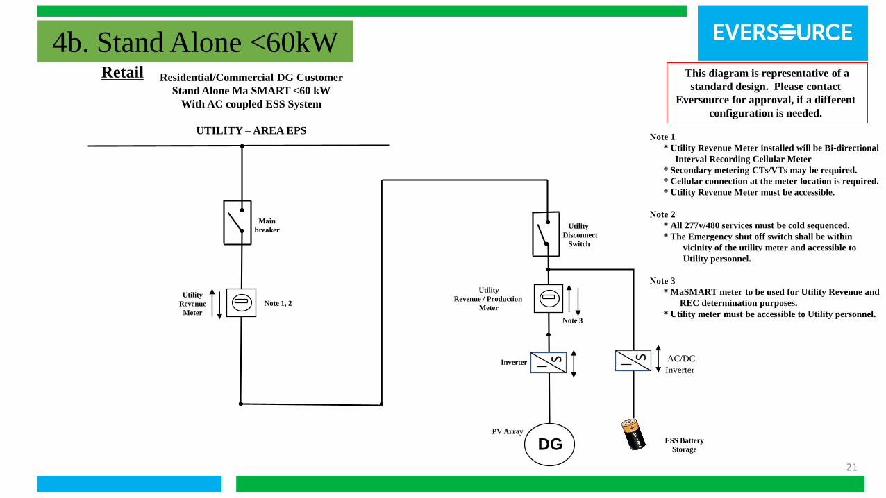
Note 1
* Utility Revenue Meter installed will be Bi-directional
Interval Recording Cellular Meter
* Secondary metering CTs/VTs may be required.
* Cellular connection at the meter location is required.
* Utility Revenue Meter must be accessible.
Note 2
* All 277v/480 services must be cold sequenced.
* The Emergency shut off switch shall be within
vicinity of the utility meter and accessible to
Utility personnel.
Note 3
* MaSMART meter to be used for Utility Revenue and
REC determination purposes.
* Utility meter must be accessible to Utility personnel.
Utility
Revenue
Meter
Note 1, 2
ESS Battery
StorageDG
SInverter
PV Array
This diagram is representative of a
standard design. Please contact
Eversource for approval, if a different
configuration is needed.
Utility
Disconnect
Switch
Main
breaker
4b. Stand Alone <60kWResidential/Commercial DG Customer
Stand Alone Ma SMART <60 kW
With AC coupled ESS System
UTILITY – AREA EPS
Retail
AC/DC
Inverter
S
Utility
Revenue / Production
Meter
Note 3

22
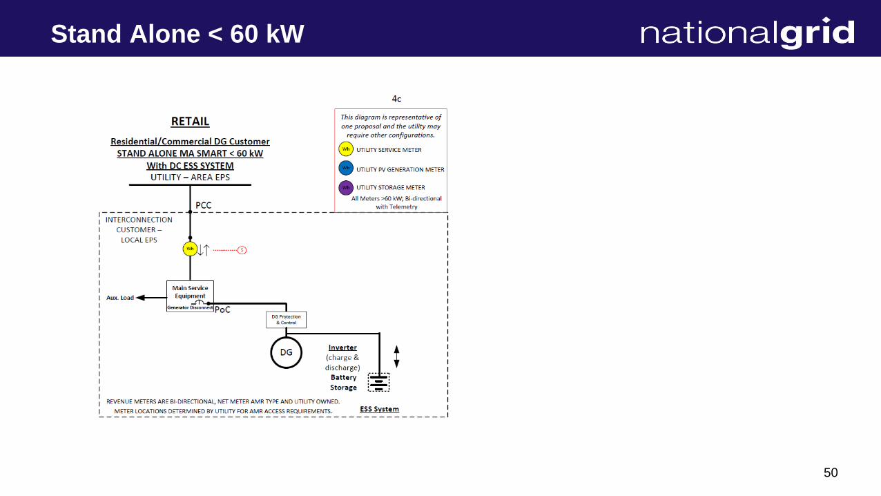
4c. Stand Alone <60kWRetail Residential/Commercial DG Customer
Stand Alone Ma SMART <60 kW
With DC coupled ESS System
UTILITY – AREA EPS
DG
Note 1
PV
Array
This diagram is representative of a
standard design. Please contact
Eversource for approval, if a different
configuration is needed.
S AC/DC
Inverter
ESS Battery
Storage
Utility /
Production
Revenue
Meter
Utility
Disconnect
Switch
Note 1
* Following utility I & R book
* All 277v/480 or instrument rated services required
to be cold sequenced as shown in diagram.
* The Emergency shut off switch shall be within the
vicinity of the utility meter and accessible to Utility\
personnel.
Note 2
* MaSMART meter to be used for Utility Revenue and
REC determination purposes.
* Utility meter must be accessible to Utility personnel.
Note 2
23
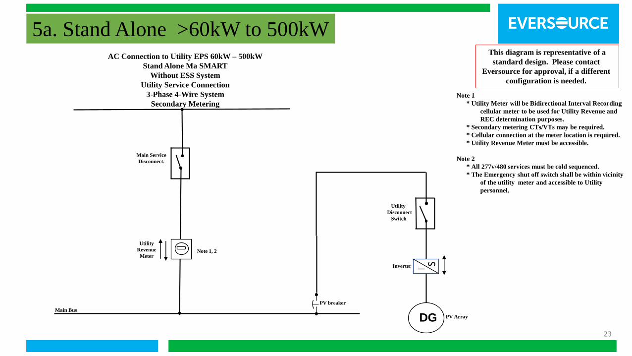
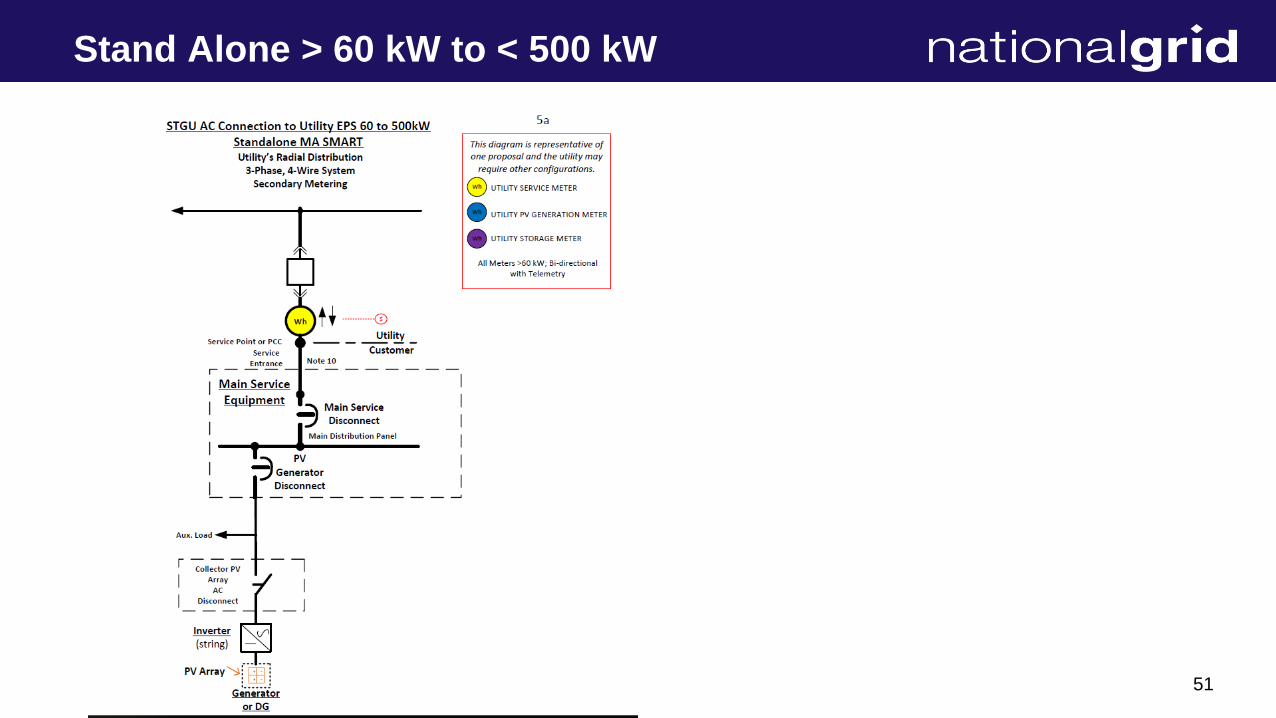
5a. Stand Alone >60kW to 500kWAC Connection to Utility EPS 60kW – 500kW
Stand Alone Ma SMART
Without ESS System
Utility Service Connection
3-Phase 4-Wire System
Secondary Metering
Utility
Revenue
Meter
DG
S
PV breaker
Main Service
Disconnect.
Inverter
PV Array
Note 1, 2
Note 1
* Utility Meter will be Bidirectional Interval Recording
cellular meter to be used for Utility Revenue and
REC determination purposes.
* Secondary metering CTs/VTs may be required.
* Cellular connection at the meter location is required.
* Utility Revenue Meter must be accessible.
Note 2
* All 277v/480 services must be cold sequenced.
* The Emergency shut off switch shall be within vicinity
of the utility meter and accessible to Utility
personnel.
This diagram is representative of a
standard design. Please contact
Eversource for approval, if a different
configuration is needed.
Utility
Disconnect
Switch
Main Bus
24
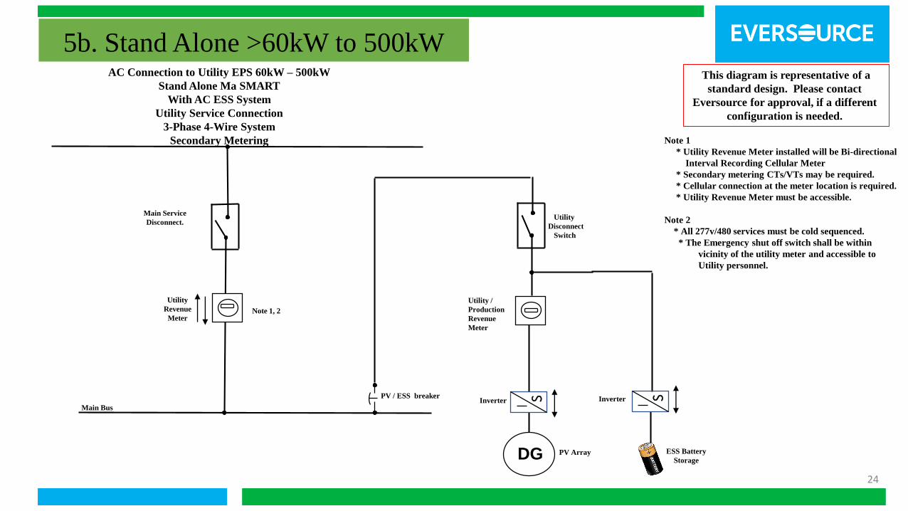
5b. Stand Alone >60kW to 500kW
Note 1
* Utility Revenue Meter installed will be Bi-directional
Interval Recording Cellular Meter
* Secondary metering CTs/VTs may be required.
* Cellular connection at the meter location is required.
* Utility Revenue Meter must be accessible.
Note 2
* All 277v/480 services must be cold sequenced.
* The Emergency shut off switch shall be within
vicinity of the utility meter and accessible to
Utility personnel.
AC Connection to Utility EPS 60kW – 500kW
Stand Alone Ma SMART
With AC ESS System
Utility Service Connection
3-Phase 4-Wire System
Secondary Metering
Utility
Revenue
Meter
PV / ESS breaker
Main Service
Disconnect.
ESS Battery
StorageDG
SInverter
PV Array
Note 1, 2
This diagram is representative of a
standard design. Please contact
Eversource for approval, if a different
configuration is needed.
Utility
Disconnect
Switch
Main Bus
SInverter
Utility /
Production
Revenue
Meter
25
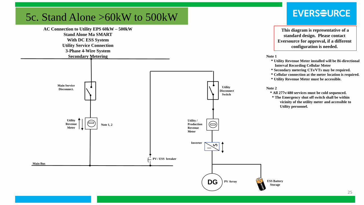
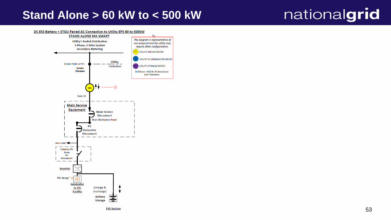
5c. Stand Alone >60kW to 500kW
Note 1
* Utility Revenue Meter installed will be Bi-directional
Interval Recording Cellular Meter
* Secondary metering CTs/VTs may be required.
* Cellular connection at the meter location is required.
* Utility Revenue Meter must be accessible.
Note 2
* All 277v/480 services must be cold sequenced.
* The Emergency shut off switch shall be within
vicinity of the utility meter and accessible to
Utility personnel.
AC Connection to Utility EPS 60kW – 500kW
Stand Alone Ma SMART
With DC ESS System
Utility Service Connection
3-Phase 4-Wire System
Secondary Metering
Utility
Revenue
Meter
PV / ESS breaker
Main Service
Disconnect.
ESS Battery
StorageDG
SInverter
PV Array
Note 1, 2
This diagram is representative of a
standard design. Please contact
Eversource for approval, if a different
configuration is needed.
Utility
Disconnect
Switch
Main Bus
Utility /
Production
Revenue
Meter

26
6a. Stand Alone >500kW
Note 1
* Utility Revenue Meter installed will be Bi-directional
Interval Recording cellular meter.
* Cellular connection at the meter location is required.
* Utility Revenue Meter must be accessible.
* Follow I&R metering requirements for Cold/Hot
sequence metering
Note 2
Polarity Mark of metering transformers is to be toward
the Utility Feed
AC Connection to Utility EPS 500kW and Greater
Stand Alone Ma SMART
With No ESS System
Utility Service Connection
3-Phase 4-Wire System
Primary Metering
Main Bus
Transformer
DG
S Inverter
PV Array
Utility
Revenue
Meter
Note 1, 2
To Utility
Metering
Main
Disconnect
This diagram is representative of a
standard design. Please contact
Eversource for approval, if a different
configuration is needed.
Utility
Disconnect
Switch
PV breaker

27
6b. Stand Alone >500kW
Note 1
* Utility Revenue, SMART and ESS Meters will be Bi-directional
Interval Recording Cellular meter. Cellular connection at the
meter location is required. Utility Revenue Meter must be
accessible.
* Follow I&R metering requirements for Cold/Hot sequence metering.
Note 2 - Polarity Mark of metering transformers is to be toward the
Utility Feed
Note 3 -Each pair of PV Array and AC coupled ESS System will be
individually metered.
AC Connection to Utility EPS 500kW and Greater
Stand Alone Ma SMART
With AC ESS System
Utility Service Connection
3-Phase 4-Wire System
Primary Metering
PV breaker
Main Bus
Main
Disconnect
Utility
Revenue
Meter
Note 1
To Utility
Metering
Note 2
DG PV Array
SInverter
ESS Battery
Storage
ESS breaker
This diagram is representative of a
standard design. Please contact
Eversource for approval, if a different
configuration is needed.
Utility
Disconnect
Switch
Utility
Disconnect
Switch
SInverter
Transformer
Utility
Prod
Meter
Note 1
To Utility
Metering
Note 2

28
6c. Stand Alone >500kW
Note 1
* Utility Revenue Meter installed will be Bi-directional
Interval Recording Cellular meter.
* Cellular connection at the meter location is required.
* Utility Revenue Meter must be accessible.
* Follow I&R metering requirements for Cold/Hot
sequence metering
Note 2
Polarity Mark of metering transformers is to be toward
the Utility Feed
AC Connection to Utility EPS 500kW and Greater
Stand Alone Ma SMART
With DC ESS System
Utility Service Connection
3-Phase 4-Wire System
Primary Metering
Main Bus
Utility
Revenue
Meter
Note 1
To Utility
Metering
Note 2
DG
Inverter
PV Array
ESS Battery
Storage
This diagram is representative of a
standard design. Please contact
Eversource for approval, if a different
configuration is needed.
Utility
Disconnect
Switch
ESS / PV breaker
Transformer
Main
Disconnect
S
29
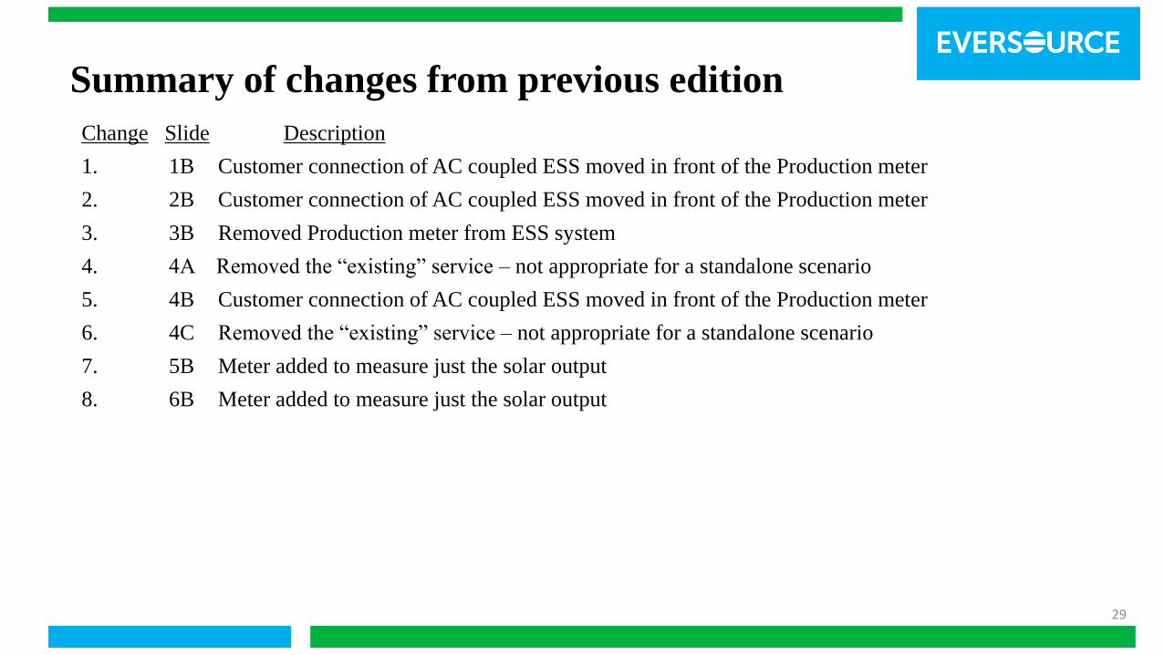
Change Slide Description
1. 1B Customer connection of AC coupled ESS moved in front of the Production meter
2. 2B Customer connection of AC coupled ESS moved in front of the Production meter
3. 3B Removed Production meter from ESS system
4. 4A Removed the “existing” service – not appropriate for a standalone scenario
5. 4B Customer connection of AC coupled ESS moved in front of the Production meter
6. 4C Removed the “existing” service – not appropriate for a standalone scenario
7. 5B Meter added to measure just the solar output
8. 6B Meter added to measure just the solar output
Summary of changes from previous edition
30
Agenda
▪ The Interconnection Process – What’s changing, what
won’t
▪ Timeline
▪ Roles of the Parties – DOER, EDC, SPA interactions
with program participants and the parties
▪ National Grid/Utilities Metering Drafts

31
The Interconnection Process
Things staying the same:
▪ EDC specific processes and tools for making,
monitoring interconnection requests
▪ Interconnection timelines
▪ EDC teams supporting the interconnection process
The MA SMART / SPA incentive application
process is designed to complement the EDC
interconnection process, not replace it
32
The Interconnection Process
Things that will change:
▪ Additional applicant-paid metering charges
▪ In behind the meter situations, need for a second,
utility installed meter for measuring system output
behind the retail meter
▪ Will require customer-installed wiring, installation of a second
meter socket
▪ Must be adequately accessible, proximate to existing utility
revenue meter
33
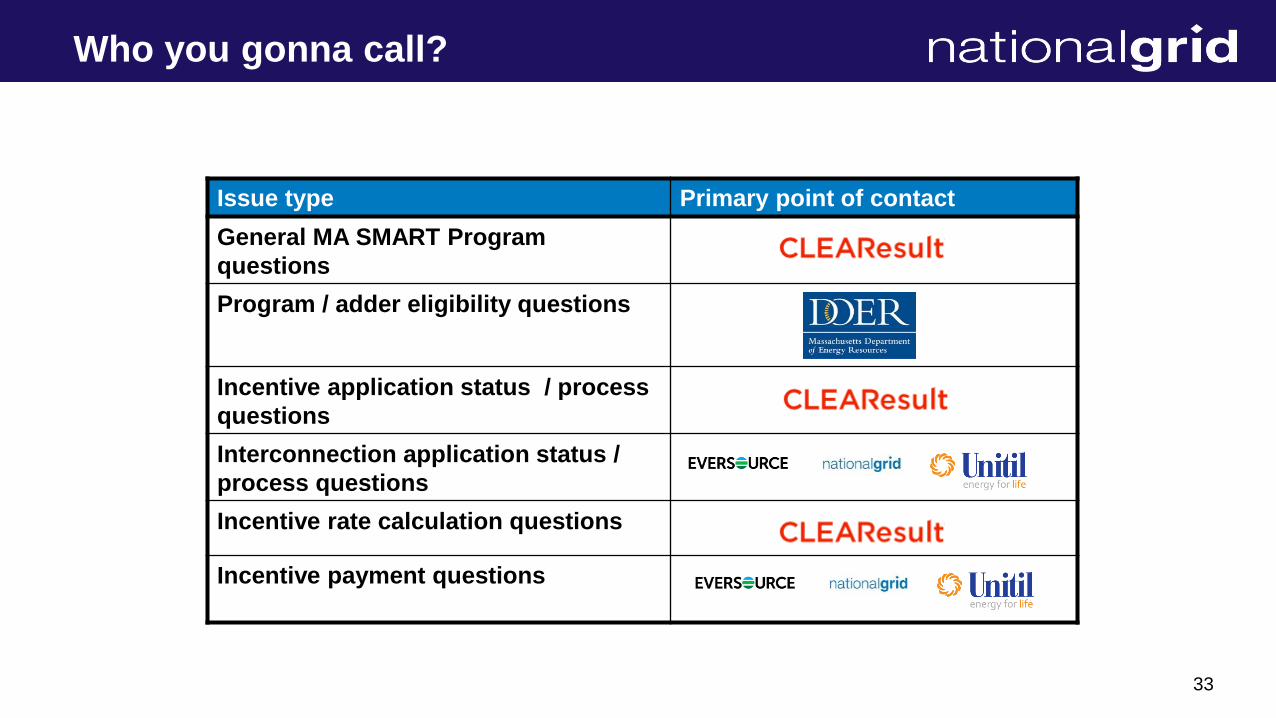
Who you gonna call?
Issue type Primary point of contact
General MA SMART Program
questions
Program / adder eligibility questions
Incentive application status / process
questions
Interconnection application status /
process questions
Incentive rate calculation questions
Incentive payment questions
34
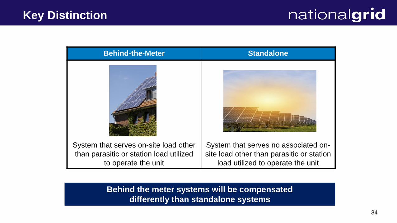
Key Distinction
Behind-the-Meter Standalone
System that serves on-site load other
than parasitic or station load utilized
to operate the unit
System that serves no associated on-
site load other than parasitic or station
load utilized to operate the unit
Behind the meter systems will be compensated
differently than standalone systems
35
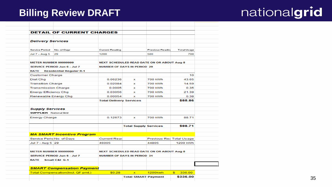
Billing Review DRAFT
36
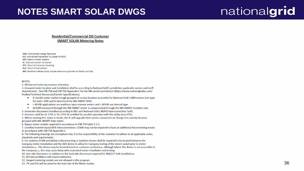
NOTES SMART SOLAR DWGS

37
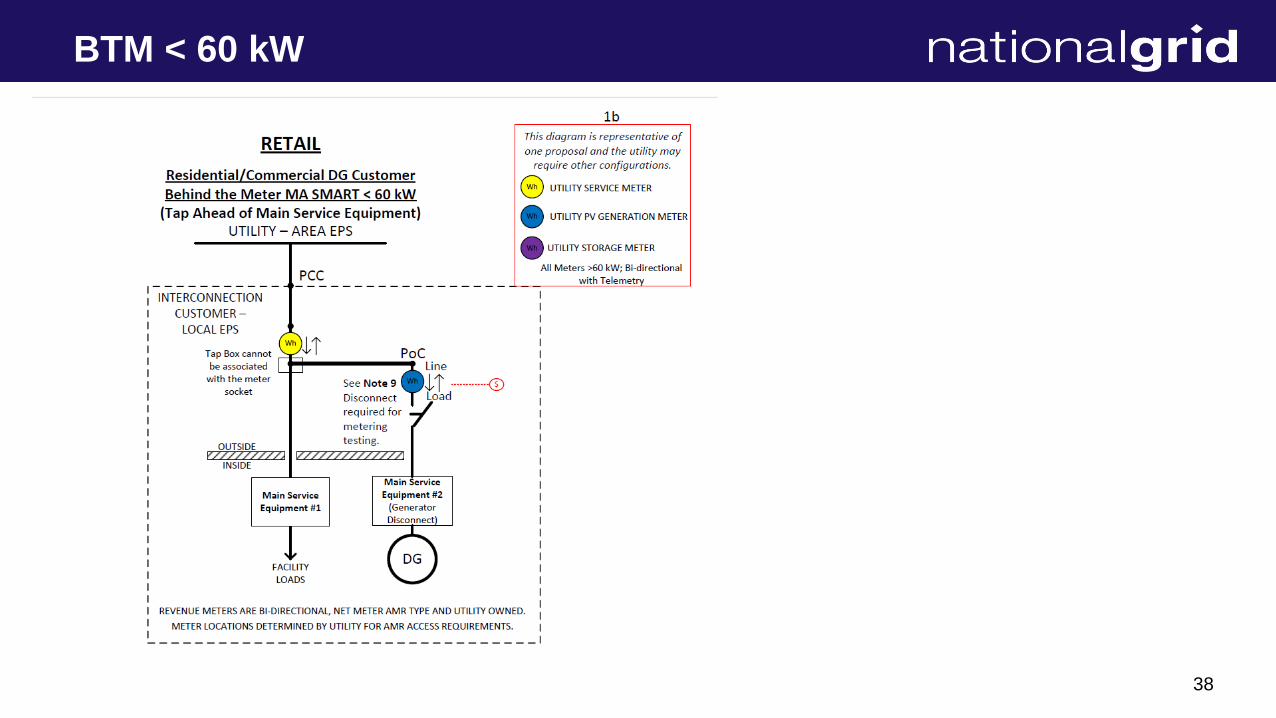
BTM < 60 kW
38
BTM < 60 kW

39
BTM < 60 kW
40
BTM < 60 kW

41
BTM >60 kW to 500 kW
42
BTM >60 kW to 500 kW
43
BTM >60 kW to 500 kW
44
BTM >60 kW to 500 kW

45
BTM > 500 KW

46
BTM > 500 KW

47
BTM > 500 KW

48
Stand Alone < 60 kW
49
Stand Alone < 60 kW
50
Stand Alone < 60 kW
51
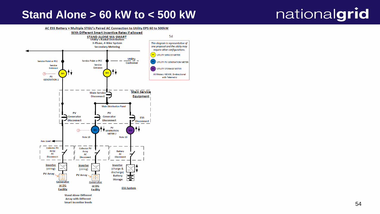
Stand Alone > 60 kW to < 500 kW

52
Stand Alone > 60 kW to < 500 kW
53
Stand Alone > 60 kW to < 500 kW
54
Stand Alone > 60 kW to < 500 kW

55
Stand Alone > 500 kW
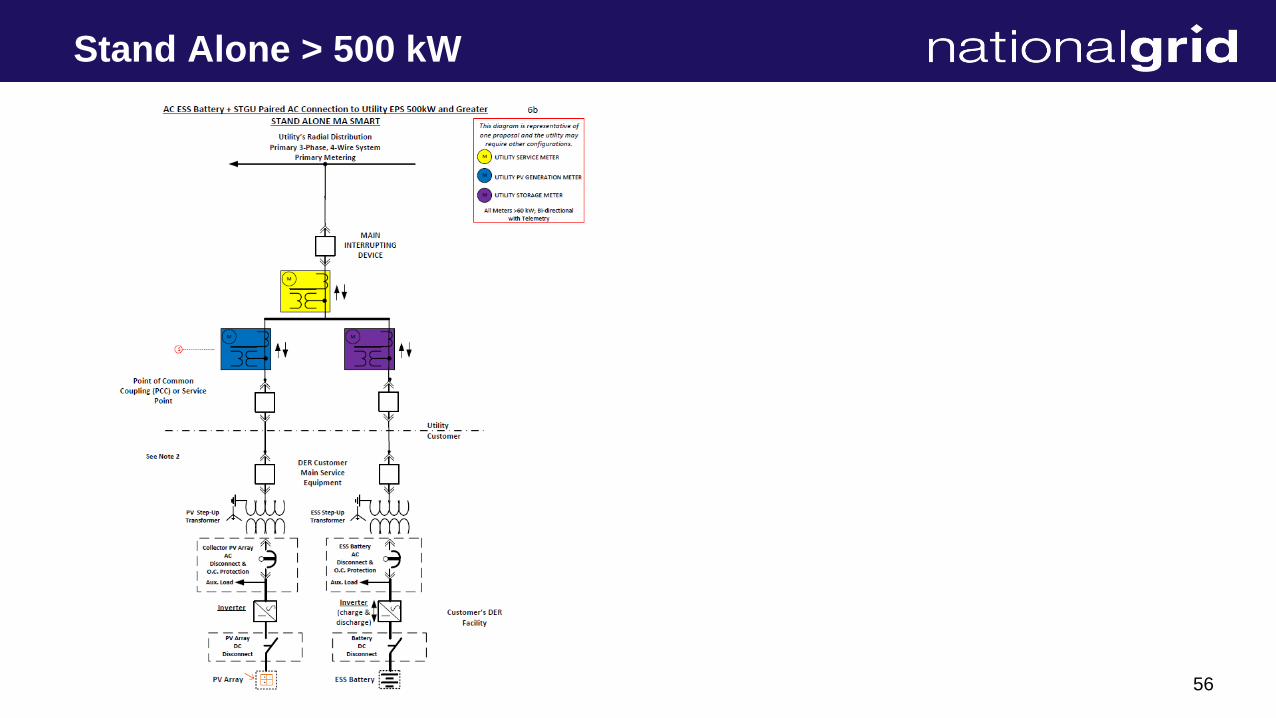
56
Stand Alone > 500 kW

57
Stand Alone > 500 kW
58
Contact Info
➢ Gerald (Jed) Ferris
➢ Smart Solar Program Manager
➢ National Grid
➢ 401 784-7364 Work
➢ 401 450-9417 Cell
➢ 245 South Main Street, Hopedale, MA.
➢ https://www.mass.gov/solar-massachusetts-renewable-target-smart
59
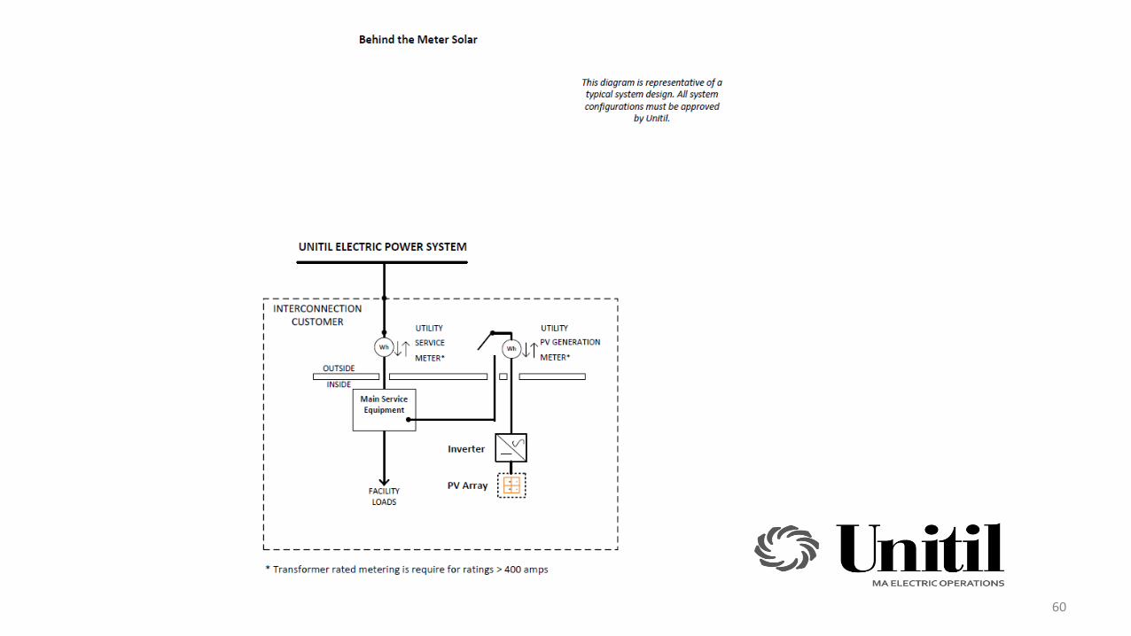
60

61
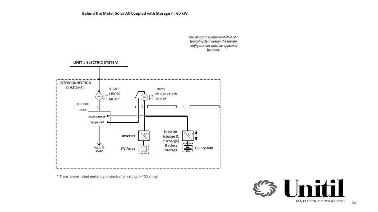
62

63

64
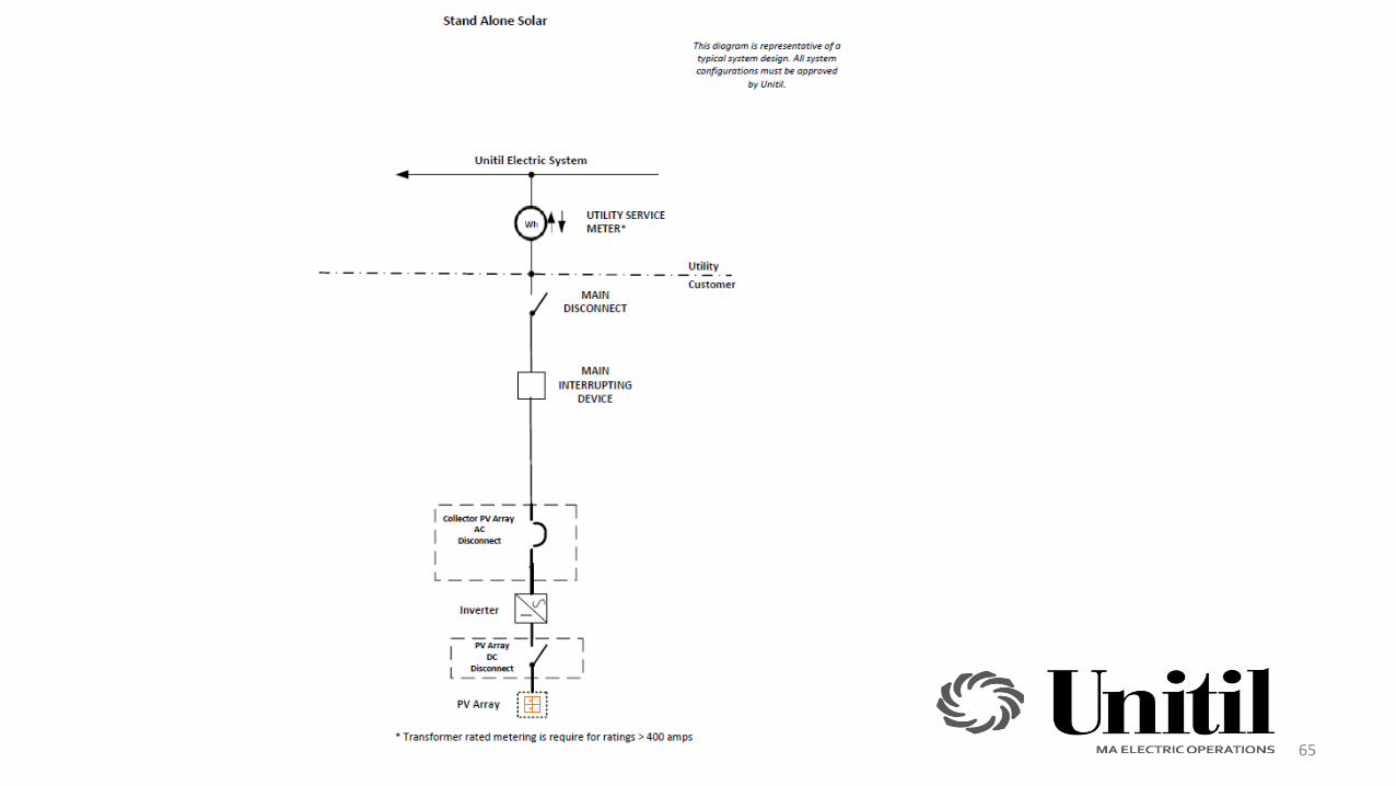
65

66
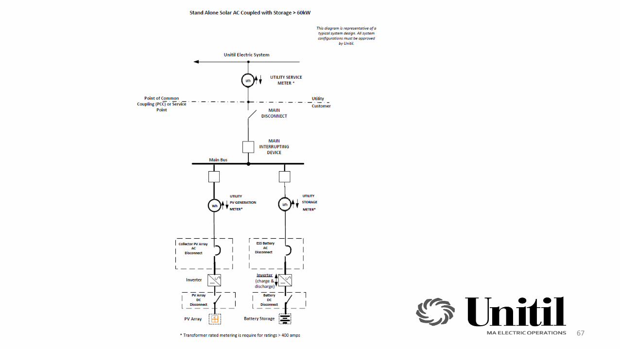
67