smart lighting_led implementation and ambient communication applications
TRANSCRIPT
8/8/2019 Smart Lighting_LED Implementation and Ambient Communication Applications
http://slidepdf.com/reader/full/smart-lightingled-implementation-and-ambient-communication-applications 1/50
Smart Lighting:LED Implementation and Ambient Communication Applications
by
Nicholas Adrian Galano
BS (University of California, Berkeley) 2008
A report submitted in partial satisfaction of the
requirements for the degree of
Master of Science
in
Engineering-Mechanical Engineering
in the
Graduate Division
of the
University of California, Berkeley
Committee in charge:Professor Alice Agogino, Chair
Professor Francesco Borrelli
Spring 2009
8/8/2019 Smart Lighting_LED Implementation and Ambient Communication Applications
http://slidepdf.com/reader/full/smart-lightingled-implementation-and-ambient-communication-applications 2/50
Table of Contents Introduction ............................................................................................................................................ 1
LED Implementation .............................................................................................................................. 2
Current Energy Usage.......................................................................................................................... 2
LED Energy Usage .............................................................................................................................. 3
Choice of luminaires ........................................................................................................................ 3
Metrics for study .............................................................................................................................. 4
Control System .................................................................................................................................... 5
Arduino Overview ........................................................................................................................... 6
Mote Overview ................................................................................................................................ 7
On/Off Switch Diagram .................................................................................................................. 7
Dimming ......................................................................................................................................... 8
How many luminaires would be needed to illuminate the lab? ....................................................... 10
Comparison ................................................................................................................................... 13
User Interface ........................................................................................................................................ 16
Introduction ...................................................................................................................................... 16
Problem Statement ............................................................................................................................ 16
Design Process ................................................................................................................................... 16
Design Testing .................................................................................................................................. 20 Ambient Communication ...................................................................................................................... 23
Related Research ................................................................................................................................ 25
Color as a form of communication .................................................................................................... 25
Science behind Color ..................................................................................................................... 25
Color Theory ................................................................................................................................. 27
Using Color technically ................................................................................................................. 28
Color and Emotional Responses .................................................................................................... 28 Actuation ........................................................................................................................................... 30
Lighting Hardware Options ........................................................................................................... 31
Arduino/Processing ........................................................................................................................ 31
Lighting Capabilities ...................................................................................................................... 32
Prototype Design ........................................................................................................................... 33
8/8/2019 Smart Lighting_LED Implementation and Ambient Communication Applications
http://slidepdf.com/reader/full/smart-lightingled-implementation-and-ambient-communication-applications 3/50
Algorithm for Response ................................................................................................................. 34
ClassPace ........................................................................................................................................ 36
Conclusion and Recommendations ........................................................................................................ 40
Appendix ............................................................................................................................................... 42
Arduino Code .................................................................................................................................... 42
Computer-Controlled On/Off Switch ........................................................................................... 42
Dimmer PWM Cycle .................................................................................................................... 42
Sample Color Wash Cycle for Ambient Color Display ................................................................... 43
Color-Emotion Test .......................................................................................................................... 45
Sample Colors Tested .................................................................................................................... 45
Sample Survey ............................................................................................................................... 45
Respondent Results........................................................................................................................ 45
References .............................................................................................................................................. 46

8/8/2019 Smart Lighting_LED Implementation and Ambient Communication Applications
http://slidepdf.com/reader/full/smart-lightingled-implementation-and-ambient-communication-applications 4/50
1
Introduction
This project builds upon the Smart Lighting project in Dr. Alice Agogino’s Berkeley
Expert Systems Technology (B.E.S.T.) research lab.
In an effort to make the laboratory more energy efficient, an efficient lighting system
using sensing and actuation (controlled by wireless motes) was installed. With this control, the
system experienced a 13% reduction in energy usagei. The B.E.S.T. laboratory implements the
current smart lighting system in which users can customize their own light settings so as to
increase user satisfaction and simultaneously reduce energy usage. In order to provide as much
control as possible, users can specify which specific luminaires are activated and at what
brightness—therefore, not all lights need be on at one time. Currently the system uses T8
fluorescent light bulbs (which reduce energy usage compared to incandescent bulbs). LEDs
possess more sustainable qualities—long life, lack of mercury, high-efficiency—when compared
to fluorescents; to what extent can the implementation of LEDs make the smart lighting system
more sustainable?
Further, because the conclusions found by Yao-Jung Wen show that the user control of
lighting preferences also contributes to a reduction in energy usage (Agogino, Granderson, Wen
p. 30)i, improvements to the control of the lighting system—the user interface—are explored.
While lighting represents a tremendous opportunity for increasing user satisfaction, its
capabilities extend beyond simple workspace illumination: the opportunities for lighting in
ambient communication applications represent a new opportunity for Smart Lighting. Using

8/8/2019 Smart Lighting_LED Implementation and Ambient Communication Applications
http://slidepdf.com/reader/full/smart-lightingled-implementation-and-ambient-communication-applications 5/50
2
both color and light actuation strategies, lighting can be used as an actor in communication in
human computer interactions.
LED Implementation
Retrofitting the smart lighting setup with LED luminaires aims to continue with the goal
of energy reduction (and overall sustainability). In order for the LED system to be implemented
in the existing Smart Lighting system, the LED luminaires must be capable of being wirelessly
controlled, dimmable, and provide the same possible maximum output (that produces
satisfactory workspace illuminance levels by IES recommendationsii).
LEDs were selected as the lighting of choice because they currently represent the next
progression in energy efficient lighting. LED lighting fixtures, while currently used mostly for
task lighting, can consume less energy than other fixtures like fluorescents or incandescents
depending on application.
Current Energy Usage
Per data collected by Wen, in the current lighting setup the fluorescent powered systemi,
the energy drawn is 3567.2 Kwh/year. This benchmark establishes that the lamps are on for 14
hours per day for 260 days per year (the amount of work days per year). This energy benchmark
defines all lights to be controlled using one switch—namely either all lights are on or off (this
represents maximum energy usage); it can be assumed energy savings due to the user-defined
control system (where each lamp can be individually controlled) will be the same for the existing
fluorescent system and the retrofitted LED system.
8/8/2019 Smart Lighting_LED Implementation and Ambient Communication Applications
http://slidepdf.com/reader/full/smart-lightingled-implementation-and-ambient-communication-applications 6/50
3
LED Energy Usage
Choice of luminaires
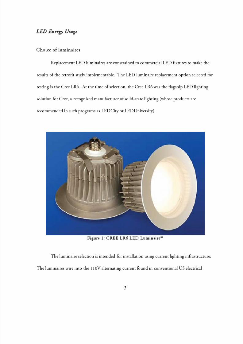
Replacement LED luminaires are constrained to commercial LED fixtures to make the
results of the retrofit study implementable. The LED luminaire replacement option selected for
testing is the Cree LR6. At the time of selection, the Cree LR6 was the flagship LED lighting
solution for Cree, a recognized manufacturer of solid-state lighting (whose products are
recommended in such programs as LEDCity or LEDUniversity).
Figure 1: CREE LR6 LED Luminaireiii
The luminaire selection is intended for installation using current lighting infrastructure:
The luminaires wire into the 110V alternating current found in conventional US electrical

8/8/2019 Smart Lighting_LED Implementation and Ambient Communication Applications
http://slidepdf.com/reader/full/smart-lightingled-implementation-and-ambient-communication-applications 7/50
4
lighting wiring standards. The luminaire is also capable of being dimmed using select
conventional lighting dimmers.
Metrics for study
In order to study the efficacy of the LED luminaire, metrics for study must be
established. These metrics are based on photometric principles. The energy that is emitted by a
luminaire covers radiated energy in both the invisible and visible (380nm to 830nm) spectrum.
Photometry describes only that radiated energy that is visible to the human eye; the photometric
equations relate the radiometric energy (total radiated energy) to photometric energy (visible
light energy) as flux:
nm
nmcradiometrimc photometri d V K
830
380
)(
where is the flux of the light source,K m is the constant that relates the spectral
efficacy,V relates the sensitivity of the eye to certain wavelengths, and
is the wavelength of
energy. The units of c photometri are lumens , which are the photometric equivalent of watts , the
unit of measurement for cradiometri .iv
While photometric flux can be used as a metric for comparison of the light sources, it is
not the ideal measurement factor because it does not take into account the actual amount of
light that reaches work surfaces (essentially, the light that can be used). Different factors can
affect the amount of light from the luminaire that actually reaches a workplane, e.g. lighting
environment or luminaire direction. For the purposes of this LED retrofit, the current Smart
Lighting setup (fluorescent) is a control group; however, because of the nature of LED
8/8/2019 Smart Lighting_LED Implementation and Ambient Communication Applications
http://slidepdf.com/reader/full/smart-lightingled-implementation-and-ambient-communication-applications 8/50
5
luminaires and the current fluorescent luminaires, the angle of photometric flux is substantially
different (fluorescent tubes radiate in all directions and rely on reflection for light to reach the
workplane, while LED luminaires direct all produced light in one direction). Therefore, directly
comparing photometric flux values (which are usually provided by lighting manufacturers) will
not be a satisfactory method of comparing newer LED systems to the current fluorescent setup.
Illuminance removes these uncertainties because it quantifies the amount of photometric
radiation that actually reaches a given surface. It is a measure of flux over a given area;
illuminance is measured inlux (where 1 lux = 1 lumen per square meter). Using the measure of
illuminance, the effectiveness of these two different types of luminaires (old and retrofitted) can
be compared.
In order for the retrofitted system to compare with the current fluorescent system, the
lighting levels should satisfy IES levels for normal office work (500 lux)ii as a maximum
benchmark.
Control System
As the light source is only a portion of the Smart Lighting system, the ability of the LED
luminaires to be controlled wirelessly with microcontrollers must also be tested. In the current
setup, one mote (wireless microcontroller) is wired to every lighting fixture to control the
luminaires to represent user preferences. The motes individually control the lighting levels of
each fixture based on commands sent wirelessly from a central server. The two main tasks that
must be accomplished by the motes are to (1) turn the lights either on or off and (2) adjust the
brightness of the luminaire.

8/8/2019 Smart Lighting_LED Implementation and Ambient Communication Applications
http://slidepdf.com/reader/full/smart-lightingled-implementation-and-ambient-communication-applications 9/50
6
Testing of the actuation of the LED luminaires is done using the Arduino
microcontrollerv . While implementation of the controllers would be accomplished using wireless
motes (as in the current system Wen’s research), the actuation capabilities of the Arduino are
similar and can be used as a test platform for quicker prototyping.
Arduino Overview
Hardware actuation testing was conducted on the Arduino Duemilanove
microcontroller.
Figure 2: Arduino Duemilanovevi
This microcontroller provides 14 digital input/output pins and 6 discrete analog input
pins (built in 10-bit A/D converters). Six of the 14 digital pins can also be reassigned for PWM
output using the Arduino’s internal PWM function. The coding environment is based off of the
Processing language, which can be viewed as a simplified version of C. All of these pins on the

8/8/2019 Smart Lighting_LED Implementation and Ambient Communication Applications
http://slidepdf.com/reader/full/smart-lightingled-implementation-and-ambient-communication-applications 10/50
7
Duemilanove are easily accessible without requiring soldering which makes it an appropriate
microcontroller for prototype testing.
Mote Overview
The 2 motes developed for testing are the MICA2 motes developed by Crossbow and the
TMoteSky by MoteIV.
Figure 3: MICA2 Motevii
The motes run TinyOS which is based off of the NesC programming language. The
motes possess both sensing and actuation capabilities on the smaller architecture using digital
outputs.
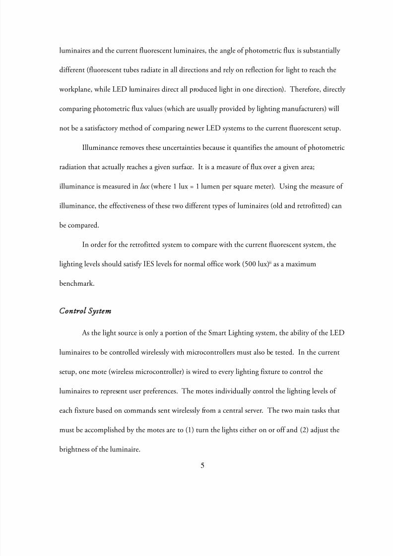
On/Off Switch Diagram
To actuate the LED luminaires either on or off, the power line of the test luminaire is
wired through a 5V relay which is actuated using an N-Channel mosfet that is controlled using a
8/8/2019 Smart Lighting_LED Implementation and Ambient Communication Applications
http://slidepdf.com/reader/full/smart-lightingled-implementation-and-ambient-communication-applications 11/50
8
digital output from the microcontroller. Figure 4 depicts the circuit diagram for the on/off
control of the luminaire.
Figure 4: Circuit Diagram for Computer-Controlled On/Off Switch
The mosfet and relay are used to protect the microcontroller from the high voltage and
current in the Alternating Current (AC) circuit that powers the luminaire. The microcontroller
is further protected by using a voltage follower that mimics the control signal. When the
controller outputs a high voltage, the relay closes and the light turns off (and vice-versa). The
dimmer circuit will be discussed further, later. Testing reveals that the on/off control circuit
operates effectively.
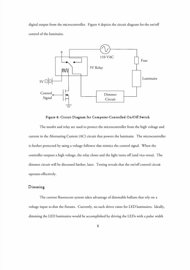
Dimming
The current fluorescent system takes advantage of dimmable ballasts that rely on a
voltage input to dim the fixtures. Currently, no such driver exists for LED luminaires. Ideally,
dimming the LED luminaires would be accomplished by driving the LEDs with a pulse width
110 VAC
5V Relay
5V
DimmerCircuit
Luminaire
Fuse
ControlSignal
8/8/2019 Smart Lighting_LED Implementation and Ambient Communication Applications
http://slidepdf.com/reader/full/smart-lightingled-implementation-and-ambient-communication-applications 12/50
mod
PW
dim
capa
curre
sinus
cycle
contr
digit
withs
lation (PW
drivers, bu
ers rely on
itors, these l
nt (power fr
oidal power
of the dim
The most
olling such a
lly controlle
tand the hig
Load
) signal.
t do allow fo
concept si
ighting dim
m the wall)
ave that po
ers, a poten
Figure
effective wa
dimmer wi
d potentiom
h voltages o
owever, the
r dimming
ilar to PW
ers alter th
is high. Th
wers the lu
iometer is p
5: Circuit D
to dim the
h a microco
eter to repla
the alternati
9
commercial
sing select c
: Using a tr
period of ti
dimmers e
inaire. In o
ysically ma
Diagram for
luminaires a
ntroller. Th
e the manu
ng current.
LED lumin
onventional
iac (a two-w
me in which
fectively sho
rder to mod
ipulated by
Typical Dim
t this curren
ere are curre
l potentiom
However, t
ires do not
lighting dim
ay semi-con
the 60Hz 1
rten the dut
ify the lengt
the user.
mmerviii
t stage of tec
ntly no obvi
eter in the d
e microcont
rovide such
mers. Thes
uctor gate)
10V alternat
cycle of th
of the duty
hnology is b
us choices
immer that
roller can be
and
ing
y
or a
an
used
8/8/2019 Smart Lighting_LED Implementation and Ambient Communication Applications
http://slidepdf.com/reader/full/smart-lightingled-implementation-and-ambient-communication-applications 13/50
10
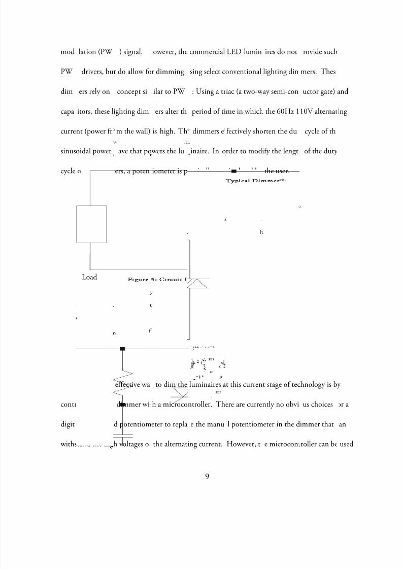
to digitally control the timing of the triac which allows for voltage to conduct (and thus control
the duty cycle).
Figure 6: Circuit Diagram for Computer-Controlled LED Dimmer
The triac is driven using a triac-driver (MOC3051) which is controlled by the control
voltage from the microcontroller; the circuit diagram in Figure 6 is adapted from the MOC3051
application noteix. Testing reveals that the proposed circuit in Figure 6 does not function to dim
the LED circuit. The error lays in the dimming circuit in Figure 6, for manually dimming theluminaire, a Leviton 705-W Push Dimmer functions to dim the luminaire.
How many luminaires would be needed to illuminate the lab?
The illuminance of the LED luminaires is calculated then used to predict the amount of
luminaires needed to replace the current setup.
The Lumen Method
The Lumen methodx calculates the luminaires needed to produce an illumination level in
a given roomi as in a test situation using the following assumptions:
110 VAC
5V
Luminaire
ControlSignal
Triac
Triac Controller
8/8/2019 Smart Lighting_LED Implementation and Ambient Communication Applications
http://slidepdf.com/reader/full/smart-lightingled-implementation-and-ambient-communication-applications 14/50
11
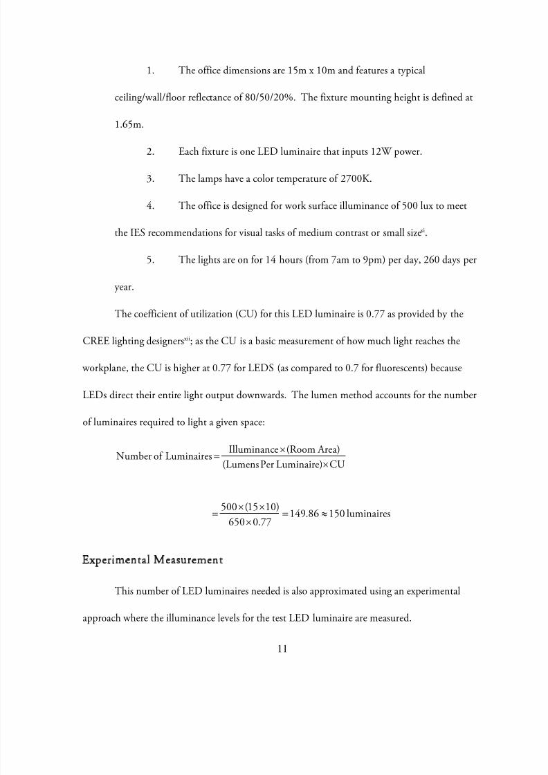
1. The office dimensions are 15m x 10m and features a typical
ceiling/wall/floor reflectance of 80/50/20%. The fixture mounting height is defined at
1.65m.
2. Each fixture is one LED luminaire that inputs 12W power.
3. The lamps have a color temperature of 2700K.
4. The office is designed for work surface illuminance of 500 lux to meet
the IES recommendations for visual tasks of medium contrast or small sizexi.
5. The lights are on for 14 hours (from 7am to 9pm) per day, 260 days per
year.
The coefficient of utilization (CU) for this LED luminaire is 0.77 as provided by the
CREE lighting designersxii; as the CU is a basic measurement of how much light reaches the
workplane, the CU is higher at 0.77 for LEDS (as compared to 0.7 for fluorescents) because
LEDs direct their entire light output downwards. The lumen method accounts for the number
of luminaires required to light a given space:
CULuminaire)Per(Lumens Area)(RoomeIlluminancLuminairesof Number
luminaires15086.14977.0650
)1015(500
Experimental Measurement
This number of LED luminaires needed is also approximated using an experimental
approach where the illuminance levels for the test LED luminaire are measured.
8/8/2019 Smart Lighting_LED Implementation and Ambient Communication Applications
http://slidepdf.com/reader/full/smart-lightingled-implementation-and-ambient-communication-applications 15/50
12
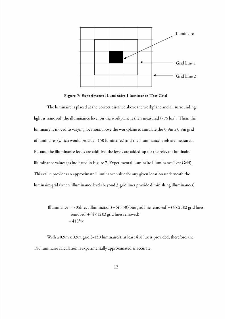
Figure 7: Experimental Luminaire Illuminance Test Grid
The luminaire is placed at the correct distance above the workplane and all surrounding
light is removed; the illuminance level on the workplane is then measured (~75 lux). Then, the
luminaire is moved to varying locations above the workplane to simulate the 0.9m x 0.9m grid
of luminaires (which would provide ~150 luminaires) and the illuminance levels are measured.
Because the illuminance levels are additive, the levels are added up for the relevant luminaire
illuminance values (as indicated in Figure 7: Experimental Luminaire Illuminance Test Grid).
This value provides an approximate illuminance value for any given location underneath the
luminaire grid (where illuminance levels beyond 3 grid lines provide diminishing illuminances).
lux 418
removed)linesgrid(3)124(removed) linesgrid(2)254(removed)linegrid(one)504(on)illuminati(direct70 eIlluminanc
With a 0.9m x 0.9m grid (~150 luminaires), at least 418 lux is provided; therefore, the
150 luminaire calculation is experimentally approximated as accurate.
Luminaire
Grid Line 1
Grid Line 2

8/8/2019 Smart Lighting_LED Implementation and Ambient Communication Applications
http://slidepdf.com/reader/full/smart-lightingled-implementation-and-ambient-communication-applications 16/50
13
Annual Energy Consumption
Annual energy consumption with luminaire on/off control (comparison setup with
fluorescent system):
year Kwh
year days
day hours watts
6552
2601412150
Year)perDays(Operating Hours)Operating(Daily (Power))Luminairesof (NumbernConsumptioEnergy Annual
Comparison
The energy consumption for the fluorescent system is calculated as3567.2KWh /year . The
LED fixture tested would represent an energy consumption increase of 183%. At its current
technological state, LED fixtures are not capable of providing enough light to reach the IES 500
lux level when used as the sole lighting source. Table 1xiii shoes energy comparisons for similar
LED lighting fixtures in the same test room.
Luminaire LumensRequiredLuminaires
Energy Usage(Watts)
Energy Used per Year (kwh)
CREE: LR6 650 150 12 6,545Philips Color Kinetics:eW Downlight Powercore 414 235 15 12,846BEGA: L8785 1800 54 26 5,121Enlux: DL Downlight 700 139 14 7,090
Juno Lighting: IC22LED 600 162 14 8,272
Table 1: LED Luminaire Energy Comparisons

8/8/2019 Smart Lighting_LED Implementation and Ambient Communication Applications
http://slidepdf.com/reader/full/smart-lightingled-implementation-and-ambient-communication-applications 17/50
14
To test the difference between the LED luminaires and fluorescent luminaires in light
attenuation, the illuminance (lux ) from the lamps is measured at varying heights. Figure 8
illustrates the test setup and Figure 9 and Figure 10 illustrate the results of the test.
Figure 8: Illuminance Attenuation Test Setup
Figure 9: Fluorescent Lighting Attenuation
Regression:y = 11.354x^[-1.0501]
R 2 = 0.9988
0.4
0.5
0.6
0.7
0.8
0.9
1
1.1
9 11 13 15 17 19 21
Iuminn
A
en
o
R
o
Distance (cm)
Fluorescent Lighting Attenuation
Fluorescent Luminaires
Regression Line
Luminaire
Lux Meter
Distance

8/8/2019 Smart Lighting_LED Implementation and Ambient Communication Applications
http://slidepdf.com/reader/full/smart-lightingled-implementation-and-ambient-communication-applications 18/50
15
Figure 10: LED Lighting Attenuation
Though these tests are conducted using higher output lamps than would be used for
higher output lamps than would be used for desk lamps, they represent general attenuation
behavior of illuminance. The tests show that LED lamps lose illuminance linearly as distance
increases while fluorescent lamps display exponential behavior and level off. Therefore at close
distances (task lighting), LEDs would be a suitable choice and possible source of energy
reduction.
Regression:y = -0.0574x + 1.5654
R 2 = 0.9952
0.4
0.5
0.6
0.7
0.8
0.9
1
1.1
9 11 13 15 17 19 21
Iuminn
A
en
o
R
o
Distance (cm)
LED Lighting Attenuation
LED Luminaires
Regression Line

8/8/2019 Smart Lighting_LED Implementation and Ambient Communication Applications
http://slidepdf.com/reader/full/smart-lightingled-implementation-and-ambient-communication-applications 19/50
16
User Interfacexiv
Introduction
To further contribute to the goals of user satisfaction, an improved control interface for
the lighting system (based on user interface metrics and principles) is designed collaboratively
with James Bonnell and Andrew Favor. The goal of this interface is to provide a novel way to
control lights in a shared office space. This interface strives to provide user customizable lighting
preferences in their work area to conserve energy, as well as improve user experience in their
place of work. No system will be effective unless used; the final project for the Graduate class
Information 213 (User Interface Design taken with James Bonnell and Andrew Favor) presents
recommendations for an improved user control of the Smart Lighting system in the laboratory.
Problem Statement
Computer interfaces will allow users to define their preferred lighting conditions as well
as quickly toggle them on and off based on the users location/mode of work.
Design Process
The lighting control prototype is developed through a process of multiple iterations and
evaluations using test subjects. Tasks are focused around the primary focus being office and
research lab users. These tasks are developed using contextual inquiry from which user needs
and ultimately three primary tasks are developed:

8/8/2019 Smart Lighting_LED Implementation and Ambient Communication Applications
http://slidepdf.com/reader/full/smart-lightingled-implementation-and-ambient-communication-applications 20/50
17
Task 1: Allowing a user to quickly turn the lights on and off with minimal technical
knowledge
Task 2: Allow a user to quickly define lighting preferences
Task 3: Allow a user to quickly change lighting according to their usage context
From these tasks, a first prototype is developed which is tested among target users.
Initial design feedback is based off of heuristic evaluation according to Nielsen’s
heuristicsxv as well as a team developed heuristic. These two sets of evaluations are numerically
combined to yield a matrix of recognized problems and their severity, along with the estimated
difficulty in remedying these problems.
The most widely recognized necessary improvements are designing help menus, and
providing more textual representation and user feedback from the interface.
The design for the main pages of the interface navigation is based on a common drop
down menu across the top of the screen which delineates the title and available options from the
main functions. A contextual help menu was located in the upper right labeled “Help” as seen in
Figure 11. This help menu and all of the other links throughout the project are designed to be
specific to the current page to provide automatic context. From this main menu, users can
activate their personal profile.
8/8/2019 Smart Lighting_LED Implementation and Ambient Communication Applications
http://slidepdf.com/reader/full/smart-lightingled-implementation-and-ambient-communication-applications 21/50
18
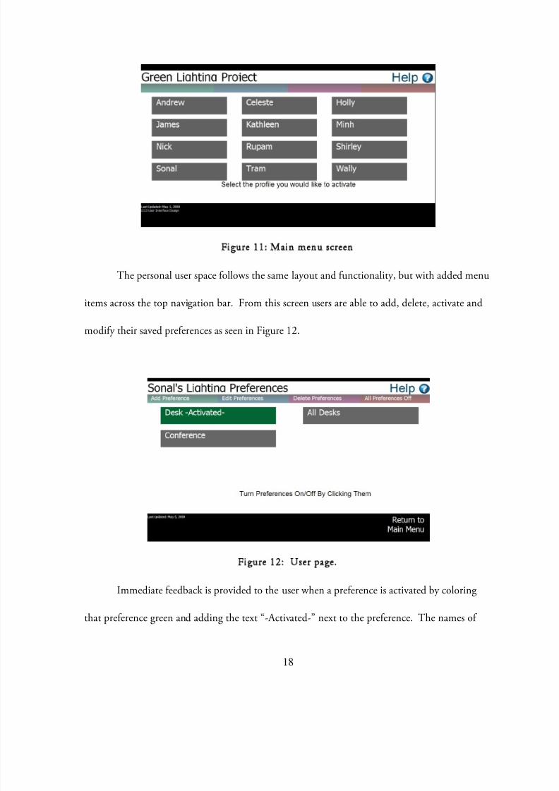
Figure 11: Main menu screen
The personal user space follows the same layout and functionality, but with added menu
items across the top navigation bar. From this screen users are able to add, delete, activate and
modify their saved preferences as seen in Figure 12.
Figure 12: User page.
Immediate feedback is provided to the user when a preference is activated by coloring
that preference green and adding the text “-Activated-” next to the preference. The names of
8/8/2019 Smart Lighting_LED Implementation and Ambient Communication Applications
http://slidepdf.com/reader/full/smart-lightingled-implementation-and-ambient-communication-applications 22/50
19
each of these buttons is based on the name the user associated with the setting in the editing
screen for preferences, minimizing memory load as described by Donald Normanxvi.
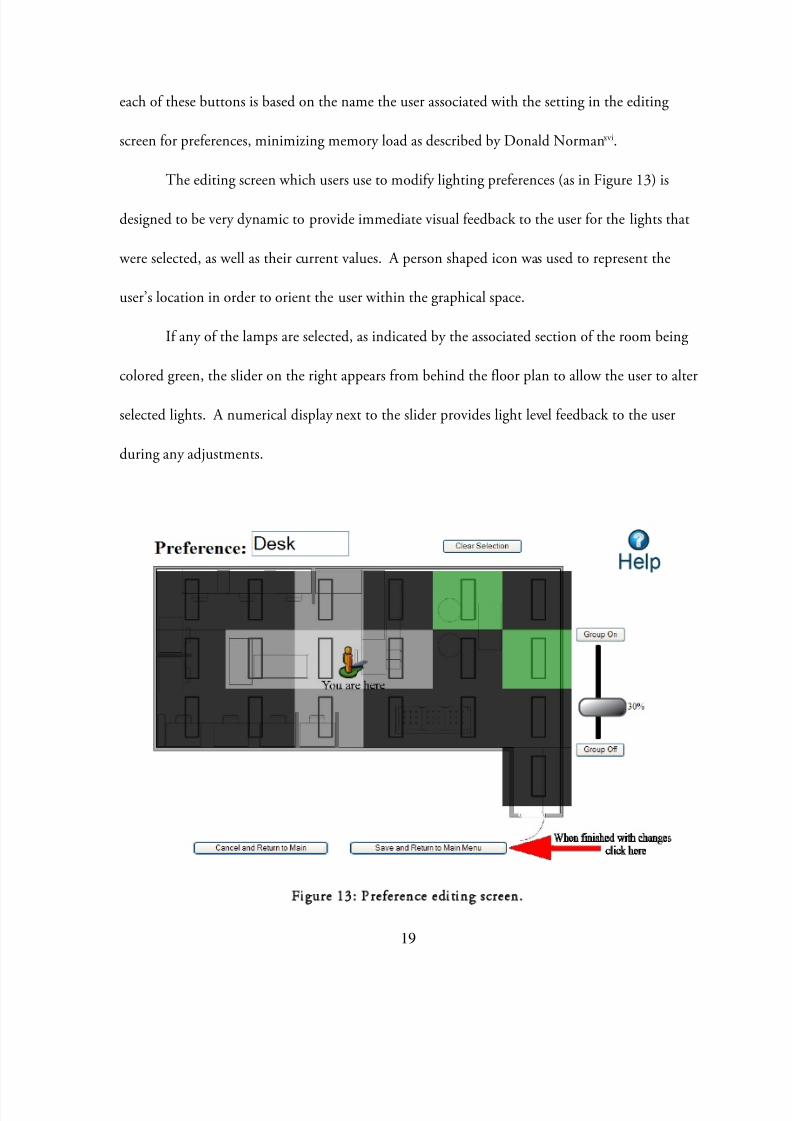
The editing screen which users use to modify lighting preferences (as in Figure 13) is
designed to be very dynamic to provide immediate visual feedback to the user for the lights that
were selected, as well as their current values. A person shaped icon was used to represent the
user’s location in order to orient the user within the graphical space.
If any of the lamps are selected, as indicated by the associated section of the room being
colored green, the slider on the right appears from behind the floor plan to allow the user to alter
selected lights. A numerical display next to the slider provides light level feedback to the user
during any adjustments.
Figure 13: Preference editing screen.
8/8/2019 Smart Lighting_LED Implementation and Ambient Communication Applications
http://slidepdf.com/reader/full/smart-lightingled-implementation-and-ambient-communication-applications 23/50
20
As soon as any alteration to the setup is made, a fly-in arrow appeared in the lower right
of the screen indicating to the user the next step available to them when they are finished with
their updates. All light value updates are also shown to the user by altering the darkness of the
color corresponding to each of the lights.
Design Testing
With this prototype, the system is evaluated using target users. To evaluate the system, 8
total testers are selected. They selected to be representative of the personas around which the
system is designed—college students and educators. Testing population is divided into two
groups, with each group testing either the control condition or the new interface first. To
further the equity in testing and minimize learning effects, anyone who has experience with the
old interface tests that interface first and similarly for those who had experience with the new
interface. Table 2 shows the testers in their groups and their demographic information.

8/8/2019 Smart Lighting_LED Implementation and Ambient Communication Applications
http://slidepdf.com/reader/full/smart-lightingled-implementation-and-ambient-communication-applications 24/50
21
User # Age Sex Major Degree
A1 24 Male ME Masters
A2 21 Male ME/MSE Bachelors
B1 31 Female Business Bachelors
B2 23 Male CS/Japanese Bachelors
B3 33 Male CS PhD
B4 26 Female Information Masters
A3 21 Male English Bachelors
A4 28 Female Education PhD
Table 2: Test subject demographic information
For quantitative evaluation of the interfaces, a set of tasks is developed for the users to
complete on both the old and new interfaces and rated them on a set of metrics for comparison.
For qualitative evaluation, we allow the testers to explore the system before completing the tasks
in a think-aloud mode so as to garner users’ intuitions about the system.
The average time of completion of the existing interface is 7 minutes 9 seconds, while for
the redesigned user interface is 5 minutes 2 seconds. On average, the completion time of
designated common tasks is reduced by 2 minutes.
While completion time is a good preliminary indicator, we also developed a quantitative
test scoring system in which a numerical score for a test was derived depending on factors such as
execution time, positive comments, negative comments, errors made in task completion, and
frequency of accessing help. The score becomes more negative as the tester’s evaluation of the
8/8/2019 Smart Lighting_LED Implementation and Ambient Communication Applications
http://slidepdf.com/reader/full/smart-lightingled-implementation-and-ambient-communication-applications 25/50
22
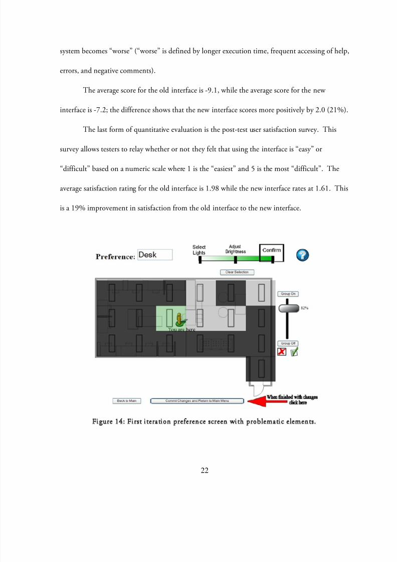
system becomes “worse” (“worse” is defined by longer execution time, frequent accessing of help,
errors, and negative comments).
The average score for the old interface is -9.1, while the average score for the new
interface is -7.2; the difference shows that the new interface scores more positively by 2.0 (21%).
The last form of quantitative evaluation is the post-test user satisfaction survey. This
survey allows testers to relay whether or not they felt that using the interface is “easy” or
“difficult” based on a numeric scale where 1 is the “easiest” and 5 is the most “difficult”. The
average satisfaction rating for the old interface is 1.98 while the new interface rates at 1.61. This
is a 19% improvement in satisfaction from the old interface to the new interface.
Figure 14: First iteration preference screen with problematic elements.

8/8/2019 Smart Lighting_LED Implementation and Ambient Communication Applications
http://slidepdf.com/reader/full/smart-lightingled-implementation-and-ambient-communication-applications 26/50
23
Qualitative observation during testing reveals two major design issues. The first major
issue is the progress bar at the top of the preference definition screen (Figure 14) which was
intended to be a simple status bar to direct the user as to what task was next, but users naturally
assumed that it is active and controls actions within the screen.
The second major issue is the use of green “check mark” and the red “x-mark”
underneath the actual light slider (Figure 14). The point of those buttons was to have users click
on the check mark when they had determined the light intensity for the group of lights they had
selected; once that group was set with the check mark, the user could then select another group
of lights to set at a different setting before committing and saving the lighting preference.
Testers struggled with the interface before finally consulting the help screen or clicking on the
check mark because it was the only button left to press.
The redesign of the user interface control of the Smart Lighting system will be more
usable based upon these recommendations. Utilizing user needs assessments and user testing
methods, a more intuitive system is developed. Being more usable will ultimately lead result in
higher user satisfaction and energy reductions.
Ambient Communication
Lighting possesses applications beyond utilitarian illumination: Through careful
application in such aspects as placement, shadows, or color spectrum, lighting can communicate
to users. It is for these reasons that lighting has many artistic applications; it has a power to elicit
emotions and communicate deeper meanings to its viewers. As Jean Rosenthal describes in
lightings use in performance, “Dancers live in light as fish live in water”. With these capabilities,
8/8/2019 Smart Lighting_LED Implementation and Ambient Communication Applications
http://slidepdf.com/reader/full/smart-lightingled-implementation-and-ambient-communication-applications 27/50
8/8/2019 Smart Lighting_LED Implementation and Ambient Communication Applications
http://slidepdf.com/reader/full/smart-lightingled-implementation-and-ambient-communication-applications 28/50
25
Related Research
Much research is being conducted in the field of ambient intelligence and
communication at many universities and research labs as it relates to human-computer
interaction. At Philips Research et al., Nevenka Dimitrova defines ambient intelligence as a
multimedia perspectivexviii.
At the MIT Media Lab, Pattie Maes and her Fluid Interfaces research group study
ambient communications and the “human-machine interaction”xix. With more related
experiments using light, Angela Chang et al. present the LumiTouch which uses light as “an
ambient representation and active data transmission” that notifies users of the context of their
communication with the other users using the LumiTouchxx.
In the area of human psychology in relation to color, work has been done to link colors
and emotions (both in medical and artistic areas of study).
Color as a form of communication
As the human reaction to color is important in ambient communication applications, the
science behind color is reviewed.
Science behind Color
In reacting to electromagnetic radiation, the human eye can only visualize a certain
portion of the range of wavelengths in the spectrum (380nm to 830nm)iv . It is the eye’s reaction
to discrete radiation wavelengths that is registered as color—light at 475nm is observed as blue,
675 nm is observed as red, etc. However, light is not usually comprised of single wavelengths,

8/8/2019 Smart Lighting_LED Implementation and Ambient Communication Applications
http://slidepdf.com/reader/full/smart-lightingled-implementation-and-ambient-communication-applications 29/50
26
but is actually a combination of energies of different wavelengths that produce different colors;
the combination of all wavelengths in the visible spectrum produces white light.
The light receptors in the human eye diverge as either rods or cones: cones are
responsible for the sensing of color, while rods sense black and white. When illuminance levels
are low, human vision becomes scotopic where the rods become primarily responsible for vision
(and the cones no longer sense light) and colors are more difficult to register. Conversely, when
illuminance levels are high, human vision becomes photopic and the cones become the primary
sensors. The anatomy of the eye reveals that the sensing area in the eye directly behind the iris—
the fovea (what one sees when focusing forward)—is comprised of only cones, which is why
when viewing in the dark (scotopic vision), it may be easier to see using peripheral vision (due to
the lack of rods in the fovea).
Using tristimulus principles, any perceived light can be broken down into three color
components of red, green, or blue basis. In its basic investigations, the International
Commission on Illumination defined these red, green, and blue component colors at 700, 546.1,
and 435.8 nm, respectively.
Knowing that light can be analyzed into three components of red, green, or blue (RGB),
any can color can also be recreated using three RGB light sources; this mixture of light is
described asadditive color mixing. (Conversely,subtractive color mixing is the mixture of
physical pigments—as opposed to colored light. Insubtractive color mixing, the primary colors
are red, yellow , and blue.)
8/8/2019 Smart Lighting_LED Implementation and Ambient Communication Applications
http://slidepdf.com/reader/full/smart-lightingled-implementation-and-ambient-communication-applications 30/50
27
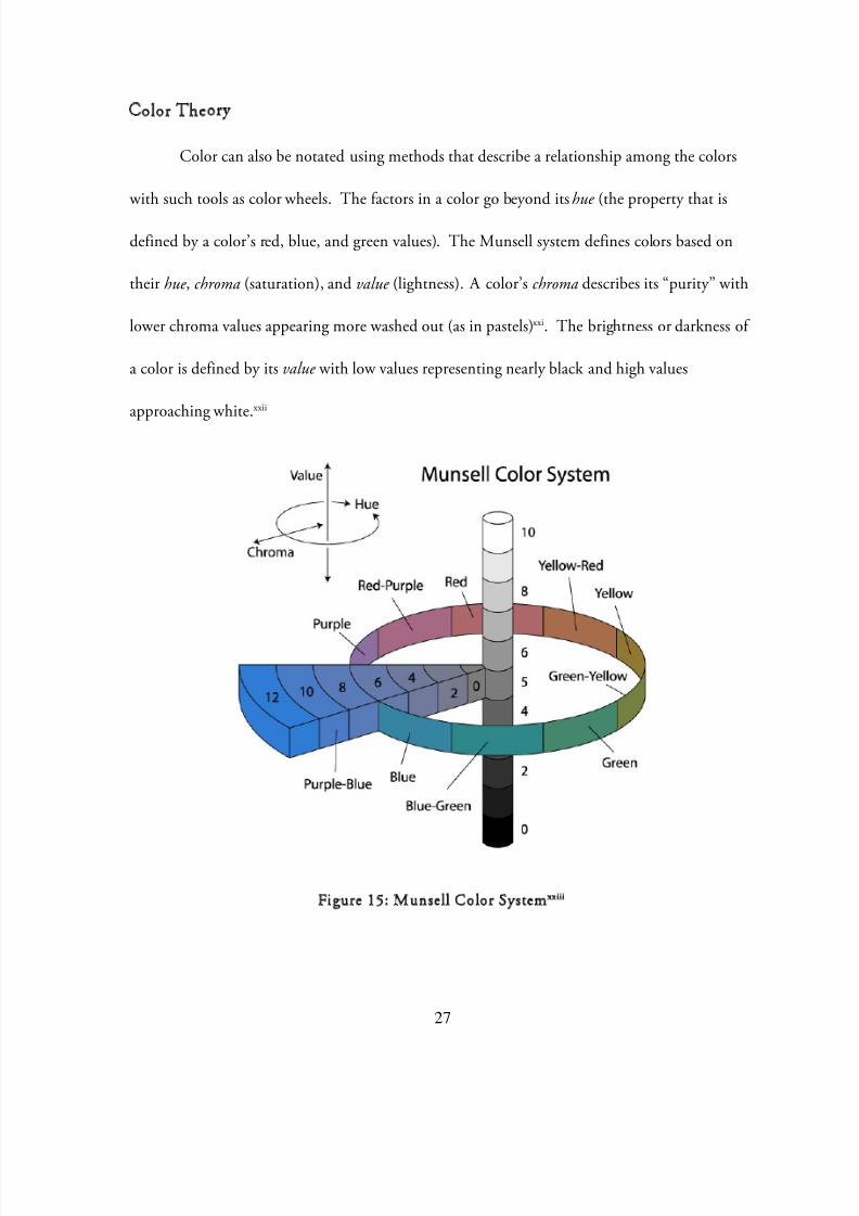
Color Theory
Color can also be notated using methods that describe a relationship among the colors
with such tools as color wheels. The factors in a color go beyond itshue (the property that is
defined by a color’s red, blue, and green values). The Munsell system defines colors based on
their hue , chroma(saturation), and value (lightness). A color’schromadescribes its “purity” with
lower chroma values appearing more washed out (as in pastels)xxi. The brightness or darkness of
a color is defined by itsvalue with low values representing nearly black and high values
approaching white.xxii
Figure 15: Munsell Color Systemxxiii
8/8/2019 Smart Lighting_LED Implementation and Ambient Communication Applications
http://slidepdf.com/reader/full/smart-lightingled-implementation-and-ambient-communication-applications 31/50
28
Using Color technically
Knowing the different ways in which color can be characterized, the interactions of color
with each other can be used a toolbox for color utilization.
Josef Alber’sInteraction of Color xxiv describes the various phenomena that govern the way
color is perceived and interacts with each other. In his study of color, Alber’s explores the
methods in which color effects can be produced by utilizing colors’ interactions; such effects
include making different colors appear alike. Alber’s highlights the “interdependence of color”
through form, amount of colors, hue of the colors, and separation of colors.
The color wheel can also be used to further describe colors in their relationship to others:
Primary hues are those that cannot be made by mixing other colors (red, green, blue); secondary
hues are those made by mixing two primary hues; tertiary hues are made by mixing a primary
with a secondary; and complementary hues are those that are opposite each other on the color
wheel (and when mixed with asubtractive method, they will create a neutral).xxv
Color and Emotional Responses
Using color as a form of ambient communication relies on color’s ability to
communicate a message to users. One such method of communication is the elicitation of a
reaction from those viewing the light.
In Health and Light xxvi John Ott explores the effects of different types of light on his
health. Though his experiments do not provide a correlation between the types of light and the
types of health effects, Ott shows a correlation between light and health effects.

8/8/2019 Smart Lighting_LED Implementation and Ambient Communication Applications
http://slidepdf.com/reader/full/smart-lightingled-implementation-and-ambient-communication-applications 32/50
29
In Color Harmony , Lesa Sawahata and Kiki Eldridge associate the types of colors with
emotions and reactions: fully saturated red physically stimulates the body; cold blues tend to
slow the mind and body; cool colors of base blue (but blended with yellows and reds,
subtractively mixed) soothe, calm, and relax; etc.
A preliminary test of these hypotheses was conducted on the E10 students in Dr.
Agogino’s class: Six colors are displayed on the projector one-by-one in a dark classroom; as each
color was displayed on the screen, the students are asked to select the adjective which best
describes the emotion they feel is elicited. Results show a strong correlation between three colors
and associated emotions:
Pale Blue: “Calm” or “Relaxed”
Orange: “Energetic” or “Cheerful”
Red: “Focused,” “Excited,” or (OTHER – written-in response)
Red is the only color that draws a substantial number of written-in responses; while the 8
listed adjectives have positive connotations, all of the written-in responses were negative. This
correlation between red andbothpositive and negative emotions is of note. (See Appendix for a
copy of the test colors, survey and results).
Despite these associations that exist between certain colors and emotions, color
psychology is viewed with skepticism with preliminary conclusions that no consistent mapping
existsxxvii, for while some colors may hold associations in some cultures, in other cultures the
associations may be completely different. The bodily response to these colors may vary based on
mental conditioning. Nevertheless, though, ambient color displays have the ability to alter a

8/8/2019 Smart Lighting_LED Implementation and Ambient Communication Applications
http://slidepdf.com/reader/full/smart-lightingled-implementation-and-ambient-communication-applications 33/50
30
setting, and much like an audience at a sports game, the setting has the ability to influence the
actors within the setting.
Actuation
In order to test the capabilities of light in ambient communication, a prototype must be
developed. The test system must be able to cycle through the range of colors on the color wheel
in order to view the effectiveness of different colors in communicating to users. For the initial
iteration of the lighting display, the lights will produce a color gradient within a lamp shade; the
colors can then be viewed from outside the lamp shade as they change.
Figure 16: Ambient Communication Prototype

8/8/2019 Smart Lighting_LED Implementation and Ambient Communication Applications
http://slidepdf.com/reader/full/smart-lightingled-implementation-and-ambient-communication-applications 34/50
31
Lighting Hardware Options
The options for producing color lighting vary across all lighting options; however, in
keeping with the low energy ethos of the Smart Lighting project, the options are narrowed to
LEDs and fluorescent bulbs. In terms of producing color, both LEDs and fluorescents can only
produce one color at a time, but LEDs can be more directly controlled using a microcontroller.
Further, the principles of additive color mixing can be utilized with LEDs in order to effectively
create an entire spectrum of colors. Therefore, the prototype will be created from an array of
red, green, and blue LEDs.
Arduino/Processing
The microcontroller used for the ambient color display is the Arduino Duemilanove
microcontroller (as is used in prototyping the LED luminaire retrofit). This microcontroller
provides 14 digital input/output pins and 6 discrete analog input pins (built in 10-bit A/D
converters). Six of the 14 digital pins can also be reassigned for PWM output using the
Arduino’s internal PWM function. The coding environment is based off of the Processing
language, which can be viewed as a simplified version of C. All of these pins on the
Duemilanove are easily accessible without requiring soldering which makes it a good
microcontroller for prototype testing. The sensing and on-board processing capabilities of the
Duemilanove are limited by its memory; however, the board possesses a serial interface, which
allows it to communicate with a computer.
By coupling the Arduino Duemilanove microcontroller with the Processingxxviii program
environment (that runs on a computer), the sensing capabilities are substantially expanded.

8/8/2019 Smart Lighting_LED Implementation and Ambient Communication Applications
http://slidepdf.com/reader/full/smart-lightingled-implementation-and-ambient-communication-applications 35/50
32
Processing is a form of object-oriented programming based off of Java. It possesses capabilities as
video and audio processing which can then be converted into actuation controls for the Arduino
board.
Figure 17: Sample Processing Programming Window and Output
The current prototype is not wireless; however, control of the ambient system can also be
conducted using wireless motes (which can also communicate with Processing using serial
communication). As the prototype develops, wireless motes will become useful for integration as
they make the ambient communication setup more mobile and versatile.
Lighting Capabilities
Using RGB LEDs, the test system is able to replicate most of the visible color spectrum
using color mixing capabilities. In order to change the relative strengths of the RGB channels,
8/8/2019 Smart Lighting_LED Implementation and Ambient Communication Applications
http://slidepdf.com/reader/full/smart-lightingled-implementation-and-ambient-communication-applications 36/50
33
each color LED is dimmed depending on the desired color. To dim the LEDs, pulse width
modulation (PWM) is employed. PWM provides a much more effective method of dimming
the LEDs as opposed to decreasing voltage provided to the diodes. The PWM method also has
the added benefit of saving energy used, for instead of the circuit wasting energy in the form of
resistance to decrease applied voltage, when the LEDs are dimmed, they are simply turned off—
expending no energy.
Prototype Design
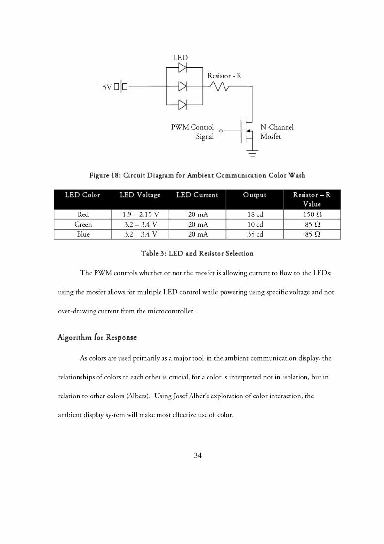
To control the LEDs, each separate color LED array is connected directly to a voltage
source; each color array circuit is controlled using an N-Channel mosfet whose gate channel
controlled using the PWM capabilities of the Arduino Duemilanove. Figure 18 depicts the
circuit diagram for one branch of the ambient color display; a total of 9 LEDs are used (3 for
each color: red, blue, and green). The ambient display contains 3 total branches, which mix
their colors together to form all possible colors; the respective brightness of each branch (and
thus color) is controlled using PWM: The PWM signal controls a mosfet gate which regulates
the voltage that flows through the circuit from a 5V power source. Table 3 depicts the LEDs
used and the corresponding resistor for each color wash branch. Together, all 3 branches form
the ambient color display prototype capable of mixing all colors.
8/8/2019 Smart Lighting_LED Implementation and Ambient Communication Applications
http://slidepdf.com/reader/full/smart-lightingled-implementation-and-ambient-communication-applications 37/50
34
Figure 18: Circuit Diagram for Ambient Communication Color Wash
LED Color LED Voltage LED Current Output Resistor – RValue
Red 1.9 – 2.15 V 20 mA 18 cd 150 ΩGreen 3.2 – 3.4 V 20 mA 10 cd 85 ΩBlue 3.2 – 3.4 V 20 mA 35 cd 85 Ω
Table 3: LED and Resistor Selection
The PWM controls whether or not the mosfet is allowing current to flow to the LEDs;
using the mosfet allows for multiple LED control while powering using specific voltage and not
over-drawing current from the microcontroller.
Algorithm for Response
As colors are used primarily as a major tool in the ambient communication display, the
relationships of colors to each other is crucial, for a color is interpreted not in isolation, but in
relation to other colors (Albers). Using Josef Alber’s exploration of color interaction, the
ambient display system will make most effective use of color.
5V
PWM ControlSignal
LED
Resistor - R
N-ChannelMosfet
8/8/2019 Smart Lighting_LED Implementation and Ambient Communication Applications
http://slidepdf.com/reader/full/smart-lightingled-implementation-and-ambient-communication-applications 38/50
35
Two main modes of communication exist for the ambient display:reflective and
proactive . The reflective modality of the display will simply provide viewers with information
that the system has gathered and analyzed; the aim of the proactive modality is to use the light
display to elicit responses from the user (such as promoting creativity—see classPace below).
The reflective mode of communication can be used by the system to communicate
different types of information as it fits within the framework of ambient communication
previously described. Possible applications include relaying information about weather forecasts,
colleague or peer availabilities, social settings, etc.
The proactive modality requires more exploration in its claim to influence the user
through light. In order to elicit such reactions, the proactive mode relies on color associations as
explored in color experiments.
In both modalities, it can be important for the ambient color display to interact with the
color of the surrounding environment. With this application, it is beneficial to examine the
complementary colors to explore the most appropriate color matchings.
Sensory Inputs
Different sensors can exist throughout space; however, to what the actuation system
responds can vary depending on desired outcome.
When combined with the analyzing power of the Processing environment, the sensing
capabilities expand with the use of cameras and microphones.
8/8/2019 Smart Lighting_LED Implementation and Ambient Communication Applications
http://slidepdf.com/reader/full/smart-lightingled-implementation-and-ambient-communication-applications 39/50
36
ClassPacexxix
The classPace project was initiated by Sohyeong Kim and Nate Gandomi for the
Tangible User Interface Class in the School of Information at UC Berkeley. Despite the
conclusion of the class, their work continues on the project with the contributions of this
research. ClassPace is an ideal case study of the applications of ambient communication using
the developed prototype.
Introduction to ClassPace
The ClassPace system is a classroom response system that aims to improve classroom
interaction using three approaches: assessing student engagement or understanding, reflecting
these factors to both students and instructor in lecture settings, and proactive fostering of student
creativity and involvement in discussion and teamwork settings.ClassPace will provide a suitable
test for the ambient display system in both reflective and proactive modalities.
The system will serve to further open the three lines of communication that exist within
an educational setting: instructor-to-students, students-to-instructor, and students-to-students.
Aggregate data gathered on student engagement (through explicit user input and implicit student
behavior) can be used to analyze pedagogical patterns to improve instructor effectiveness. By
visualizing student engagement and understanding,ClassPace will allow students to diagnose
their own progress and understanding. Additionally, instructors will be able to identify which
topics require further time and attention. ClassPace will provide a way for students to share and
view non-verbal, non-textual feedback within the context of a classroom.

8/8/2019 Smart Lighting_LED Implementation and Ambient Communication Applications
http://slidepdf.com/reader/full/smart-lightingled-implementation-and-ambient-communication-applications 40/50
37
Development of System
Input Device
Students will relate their engagement to theClassPace system using an input device that
translates a spectrum of input values ranging from not engaged to highly engaged. Currently the
sensor is a foot pedal that is discrete and has natural affordances to fast and slow (which relate to
the pace of the class).
This data will inform the ambient lighting display as to how to communicate to the class.
Instructors in small class settings often gauge student interest by observing factors such as body
language. Ideally, futureClassPace iterations will be able to mimic such observations with
sophisticated input sensors.
Ambient Output Display
Data from ClassPace inputs will be transformed into a visualization using the ambient
output display.
Instead of using a display which provides and presents each individual user as an icon,
the sensory input will be aggregated and communicated by lighting a wall (or other surface) with
a color gradient. To communicate the overall class interest, the color gradient will shift
depending on the input. The design change of moving to a color gradient is to situate the
communication in a more familiar environment to the users (teachers and students)xvii: The goal
for mapping colors to class pace opinion is to present the data to users using associations between
the two.
8/8/2019 Smart Lighting_LED Implementation and Ambient Communication Applications
http://slidepdf.com/reader/full/smart-lightingled-implementation-and-ambient-communication-applications 41/50
38
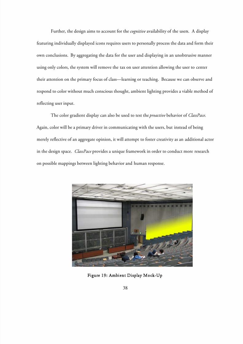
Further, the design aims to account for thecognitive availability of the users. A display
featuring individually displayed icons requires users to personally process the data and form their
own conclusions. By aggregating the data for the user and displaying in an unobtrusive manner
using only colors, the system will remove the tax on user attention allowing the user to center
their attention on the primary focus of class—learning or teaching. Because we can observe and
respond to color without much conscious thought, ambient lighting provides a viable method of
reflecting user input.
The color gradient display can also be used to test the proactive behavior of ClassPace .
Again, color will be a primary driver in communicating with the users, but instead of being
merely reflective of an aggregate opinion, it will attempt to foster creativity as an additional actor
in the design space. ClassPace provides a unique framework in order to conduct more research
on possible mappings between lighting behavior and human response.
Figure 19: Ambient Display Mock-Up
8/8/2019 Smart Lighting_LED Implementation and Ambient Communication Applications
http://slidepdf.com/reader/full/smart-lightingled-implementation-and-ambient-communication-applications 42/50
39
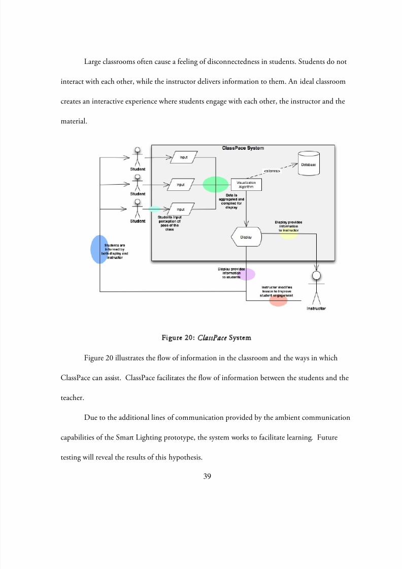
Large classrooms often cause a feeling of disconnectedness in students. Students do not
interact with each other, while the instructor delivers information to them. An ideal classroom
creates an interactive experience where students engage with each other, the instructor and the
material.
Figure 20: ClassPaceSystem
Figure 20 illustrates the flow of information in the classroom and the ways in which
ClassPace can assist. ClassPace facilitates the flow of information between the students and the
teacher.
Due to the additional lines of communication provided by the ambient communication
capabilities of the Smart Lighting prototype, the system works to facilitate learning. Future
testing will reveal the results of this hypothesis.
8/8/2019 Smart Lighting_LED Implementation and Ambient Communication Applications
http://slidepdf.com/reader/full/smart-lightingled-implementation-and-ambient-communication-applications 43/50
40
Conclusion and Recommendations
After the successful installation of the user-customizable fluorescent lighting system, new
avenues exist for the growth of Smart Lighting. While LEDs are generally considered to be the
next step for energy-efficient lighting, many commercial options are still scarce for LED lighting
systems. Though the fixtures generally do consume less energy, the amount of lighting produced
is also substantially less than with current fluorescent lights. Thus energy consumption for a
room lit by LEDs would require nearly twice as much energy as the same room lit by fluorescent
LEDs. Therefore, LEDs are currently not an ideal choice for a general lighting solution.
However, LEDs do show preliminary promise in close uses (such as task lighting) due to
their attenuation patterns: While fluorescent light seems to possess an inversely proportional
relationship to distance from the light source, LED lighting is more linear. This would suggest
that using LED lighting is more applicable in situations closer to the source such as task lighting
(or as in display lighting where they are used now).
Avenues for growth of Smart Lighting exist beyond simple illumination, as well.
Lighting can be used in ambient communication applications. By being reflective of
information or proactive actors in a situation, lighting has many possibilities. To be better used
in a proactive manner, the ways in which lighting can be used are examined: color, actuation,
etc. Some existing claims correlate color to emotion and while preliminary tests conducted in
this area confirm such a relationship, it does not link colors to previously linked emotions.
Thus, preliminary research shows possibilities for uses of Smart Lighting as a form of ambient
8/8/2019 Smart Lighting_LED Implementation and Ambient Communication Applications
http://slidepdf.com/reader/full/smart-lightingled-implementation-and-ambient-communication-applications 44/50
41
communication but further research must be conducted in this area to clearly define such
methods.

8/8/2019 Smart Lighting_LED Implementation and Ambient Communication Applications
http://slidepdf.com/reader/full/smart-lightingled-implementation-and-ambient-communication-applications 45/50
42
Appendix
Arduino Code
Computer-Controlled On/Off SwitchThis code controls whether or not the lamp is controlled on or off. This code controls thecircuitry detailed in Figure 4.
/** Nicholas Galano** Turn a light on/off using MOSFET control**/
//Variable Definitionint outPin = 11; //Light sensor analog pin input #int inPin = 2; //input pinint buttonState = 0; //
void setup() {pinMode (outPin, OUTPUT); //sets digital pin for outputpinMode (inPin, INPUT); //sets digital pin for input
}
void loop () {buttonState = digital Read (inPin);if (buttonState == HIGH) { //If the button is pressed
digitalWrite(13,HIGH); //Actuate the light (High Voltage -> turns on mosfet -> closesrelay)
}}
Dimmer PWM CycleThis code outlines the manual PWM cycle utilized for controlling the TRIAC for the LEDluminaire dimmer. This code controls the circuitry detailed in Figure 6.
/** Nicholas galano** Manual PWM Output* Test the Digital IO ports for ability for custom duty cycle

8/8/2019 Smart Lighting_LED Implementation and Ambient Communication Applications
http://slidepdf.com/reader/full/smart-lightingled-implementation-and-ambient-communication-applications 46/50
43
**/
float T = 100/12; //Periodfloat duty = 0.25; //initialize duty cycle (from 0 - 1)float a = 0; //initialize duty timefloat b = 0; //initialize off time
int controlPin = 7; //Digital Pin
void setup(){pinMode(controlPin, OUTPUT);
}
void loop(){a = duty*T; //set duty cycle timeb = T - a; //set off cycle timedigitalWrite(controlPin,HIGH); //turn ondelay(a);digitalWrite(controlPin,LOW); //turn off delay(b);
}
Sample Color Wash Cycle for Ambient Color DisplayThis code showcases the color wash ambient display by cycling through the color wheel. Thiscode is used to control the circuit exhibited in
/** LED Color Mixing* Nick Galano* BEST Lab** 3-1-09** Show Color Mixing Capabilities**/
//Variablesint redpin = 9;int greenpin = 10;int bluepin = 11;

8/8/2019 Smart Lighting_LED Implementation and Ambient Communication Applications
http://slidepdf.com/reader/full/smart-lightingled-implementation-and-ambient-communication-applications 47/50
44
int redval = 0;int greenval = 254;int blueval = 120;
int rindex = 0;int gindex = 0;int bindex = 0;
void setup() {pinMode(redpin, OUTPUT);pinMode(greenpin, OUTPUT);pinMode(bluepin, OUTPUT);
}
void loop() {if (rindex == 0) {
redval=redval+1;if (redval == 255) rindex = 1;
}if (rindex == 1) {
redval=redval-1;if (redval == 1) rindex = 0;
}
if (gindex == 0) {greenval=greenval+1;if (greenval == 255) gindex = 1;
}if (gindex == 1) {
greenval=greenval-1;if (greenval == 1) gindex = 0;
}
if (bindex == 0) {blueval=blueval+1;if (blueval == 255) bindex = 1;
}if (bindex == 1) {
blueval=blueval-1;if (blueval == 1) bindex = 0;
}

8/8/2019 Smart Lighting_LED Implementation and Ambient Communication Applications
http://slidepdf.com/reader/full/smart-lightingled-implementation-and-ambient-communication-applications 48/50
45
analogWrite(redpin,redval);analogWrite(greenpin,greenval);analogWrite(bluepin,blueval);delay(80);
}
Color-Emotion Test
Sample Colors Tested
Sky Blue Orange Magenta
Green Red Yellow
Sample SurveyDemographic Information:
Are you color blind? Y NGender? M F What Country did you grow up in?
Emotions to be selected: Energetic Focused Excited Friendly Cheerful Calm Relaxed Ready
Other: ______________________
Respondent ResultsColor
emotion Pale Blue Orange Magenta Green Yellow Redenergetic 7 9 8 7 3focused 2 3 2 6 1 9

8/8/2019 Smart Lighting_LED Implementation and Ambient Communication Applications
http://slidepdf.com/reader/full/smart-lightingled-implementation-and-ambient-communication-applications 49/50
46
excited 3 12 2 3 9friendly 2 4 4 3 7 1cheerful 6 5 6 8calm 21 3 5 4 1relaxed 12 3 2 2 2
ready 3 3 4 3 3OTHER 1 4 1 1 8
Table 4: Respondent Results of Color-Emotion Test
References
i Agogino, A.M, J. Granderson and Y.J. Wen, Efficient Lighting by Sensing and Actuating with MEMS 'Smart Dust Motes': A Feasibility Study (Final Report, Energy Innovations Small Grant (EISG) Program, Grant #03-20). 2007ii “IESNA Lighting Handbook ”, 2000, Illuminating Engineering Society of North America, New York, NY.iii “CREE LR6.” WarnHomeCenter. 2009.<http://www.wamhomecenter.com/productcart/pc/catalog/lr6_product_24_detail.jpg>iv DeCusatis, Casimer. Handbook of Applied Photometry . Woodbury, NY: AIP Press, 1997.v Arduino. 26 March 2009. 12 May 2009. <http://arduino.cc>vi Arduino Duemilanove . 26 March 2009. 12 May 2009<http://arduino.cc/en/uploads/Main/ArduinoDuemilanove.jpg>viiCrossbow . 2009. 12 May 2009.<http://www.xbow.com/Products/Product_images/Wireless_images/MICA2_Lg.jpg>viiiHarris, Tom. "How Dimmer Switches Work." HowStuffWorks.com. 13 August 2002. 12 May 2009.<http://home.howstuffworks.com/dimmer-switch.htm>.ix “6Pin DIP Random-Phase Optoisolators Triac Drivers”. Motorola MOC3051/D. 1995 Motorla, Inc.x “Indoor Bill of Material Estimator ”, Technical Data, T-21, 2005, GE Lighting System, Inc.xi “IESNA Lighting Handbook ”, 2000, Illuminating Engineering Society of North America, New York, NY.xiiHall, Ron. “Overview of LEDs in General Illumination Applications”. CREE LED Light. 8 December 2008.<http://www.energync.net/conference/presentations/April%208/New%20Technology%20Showcase%20NC%20Opportunities/Ron_Hall.pdf>xiii “eW Downlight Powercore.” Color Kinetics. 2009.<http://www.colorkinetics.com/support/datasheets/eW_Downlight_Powercore_2700K_SpecSheet.pdf>“Bega Lighting.” Bega-US. 2009. <http://www.bega-us.com/Limburg_productdetail.aspx?groupid=L13&itemid=5547&familyid=25>“EnLux DL Lighting.” enLux Lighting. 2009. <http://www.enluxled.com/datasheets/DL_DataSheet2.pdf>“Juno 6” Lighting.” Juno Recessed and Trac Lighting.<http://www.junolightinggroup.com/product_detail.asp?ino=9287&Sel_Id=17222&brand=1>xiv Work with James Bonnell and Andrew Favorxv Nielsen, Jakob. “Ten Usability Heuristics.”UseIt.com. 2005. 12 April 2009.<http://www.useit.com/papers/heuristic/heuristic_list.html>xviNorman, Donald. The Design of Everyday Things.London: MIT, 1998.xvii Privat, Gilles. “Ambient Communication: When Devices Disappear”.xviii Aarts, Emile. “Ambient Intelligence: A multimedia Perspective.”IEEE Multimedia11.1 (2004): pp. 12-19.xixFluid Interfaces Group. MIT Fluid Interaces Research Group. 12 April 2009.<http://fluid.media.mit.edu/projects.php>xxChang, Angela.Lumitouch. 2002. 12 May 2009.

8/8/2019 Smart Lighting_LED Implementation and Ambient Communication Applications
http://slidepdf.com/reader/full/smart-lightingled-implementation-and-ambient-communication-applications 50/50
xxi “Munsell Chroma.” Apple Painter. 2009. <http://www.applepainter.com/Chap03/>xxii Kuehni, Rolf. “The Early Development of the Munsell System.”Color Research and Application.27.1 (2001): pp20-27.xxiii “Munsell Color System.” Wikipedia. 2007. <http://en.wikipedia.org/wiki/Munsell_color_system>xxiv Albers, Josef.Interaction of Color . New Haven and London: Yale University Press, 1963.xxv Eldridge, Kiki and Sawahat, Lesa.Complete Color Harmony Workbook.Beverly, Massachusetts: RockportPublishers, 2007.xxvi Ott, John. Health and Light.New York, NY: John Ott Pictures Inc., 1973.xxvii Boycottchapter27. “The Psychology of Color”. HupPages. 2008. 12 May 2009.<http://hubpages.com/hub/The-Psychology-of-Color>xxviii Processing 1.0. 26 April 2009. 12 May 2009. <http://processing.org>xxix Work with Sohyeong Kim and Nate Gandomi