smart grid communications - electrical & computer ...yhe/my papers/thesis/msc jian... · web...
TRANSCRIPT

OPTIMAL RESOURCE ALLOCATION FOR LTE UPLINK SCHEDULING IN SMART
GRID COMMUNICATIONS
by
Jian Li
B.Sc., North China University of Technology, China, 2011
A thesis
presented to Ryerson University
in partial fulfillment of the
requirements for the degree of
Master of Applied Science
in the Program of
Computer Networks
Toronto, Ontario, Canada, 2013
© Jian Li 20

Author’s Declaration
I hereby declare that I am the sole author of this thesis.
I authorize Ryerson University to lend this thesis to other institutions or individuals for the
purpose of scholarly research.
Author’s Signature:
I further authorize Ryerson University to reproduce this thesis by photocopying or other
means, in total or in part, at the request of other institutions or individuals for the purpose
of scholarly research.
Author’s Signature:
ii

Abstract
Optimal Resource Allocation for LTE Uplink Scheduling in
Smart Grid Communications
© Jian Li 2013
Master of Applied Science
Program of Computer Networks
Department of Electrical and Computer Engineering
Ryerson University
The success of the smart grid greatly depends on the advanced communication
architectures. An advanced smart grid network should satisfy the future demands of the
electric systems in terms of reliability and latency. The latest 4th-generation (4G) wireless
technology, Long Term Evolution (LTE), is a promising choice for smart grid wide area
networks, due to its higher data rates, lower latency and larger coverage. However, LTE is
not a dedicated technology invented for smart grid, and it does not provide Quality of
Service (QoS) guarantee to the smart grid applications. In this thesis, we propose an optimal
LTE uplink scheduling scheme to provide scheduling time guarantee at the LTE base station
for different class of traffic, with a minimal number of total resource blocks. A lightweight
heuristic algorithm is proposed to obtain the optimal allocation of resource blocks for each
class of traffic. The simulation results demonstrate that the proposed optimal scheduling
scheme can use less resource blocks to satisfy the scheduling time requirements, compared
to the two existing scheduling schemes (the Large-Metric-First scheduling scheme and the
iii

Guaranteed Bit Rate (GBR)/Non-GBR scheduling scheme). As the multi-cell network system,
the network performance of LTE may be still deteriorated by load imbalance. The
unbalanced load among multiple cells leads to higher delay and higher packet drop rate in
the higher-loaded cell, or an underutilization of resources in the lower-loaded cell. In order
to solve this problem, a LTE load balancing algorithm is proposed aiming at finding the
optimal handover operations between the overloaded cell and possible target cells. The
simulation results show that the proposed load balancing algorithm can relieve network
resources overload and increase the network bandwidth efficiency.
iv

Acknowledgement
I would like to take the opportunity to express my gratitude to my supervisor, Dr. Yifeng He
and Dr. Ling Guan for their tremendous guidance and kind supports throughout the duration
of my graduate studies.
I would like to acknowledge the Computer Networks Department and the School of
Graduate Studies at Ryerson University for their support in terms of financial aid, and work
experience as a graduate assistant. Thanks to Dr. Bobby Ma for his overall guidance
throughout my Master of Applied Science duration. Thanks to Mr. Arseny Taranenko to help
us setup and manage the lab environment. Thanks to Dr. Xiaoli Li for her excellent
assistances.
I received a lot of support during the THESL-RUCUE project. I would like to thank all
members working in this group. It was an unforgettable opportunity for me to work
together. I would like also thank all colleagues of Ryerson Multimedia Research Laboratory; I
extend my sincere appreciation for their support and valuable suggestions on various
technical aspects and sharing some lighter moments whenever required.
I would also like to thank my defense committee for taking the time and effort to review my
work and provide me with their insightful comments.
I can never find the words to thank my beloved father and mother. Without them, I could
never reach my current stage in life. I never felt alone with their kind support and
encourages.
v

Contents
Chapter 1 Introduction...........................................................................................................1
1.1 Smart Grid Communications.......................................................................................1
1.2 Long Term Evolution (LTE)..........................................................................................4
1.3 Challenge....................................................................................................................7
1.4 Existing Work..............................................................................................................8
1.5 Thesis Contributions...................................................................................................9
1.6 Organization of Thesis................................................................................................9
Chapter 2 Background..........................................................................................................11
2.1 Technical Overview of LTE........................................................................................11
2.1.1 Introduction........................................................................................................... 11
2.1.2 SC-FDMA and OFDMA.......................................................................................13
2.1.3 Control signaling for uplink scheduling.............................................................17
2.2 Literature Review.....................................................................................................17
2.2.1 Related work on smart grid WAN......................................................................17
2.2.2 Related work on LTE QoS..................................................................................19
2.2.3 Related work on LTE load balancing..................................................................24
2.3 Chapter Summary.....................................................................................................25
vi

Chapter 3 LTE Uplink Scheduling Algorithm for Smart Grid ..................................................26
3.1 Introduction..............................................................................................................26
3.2 System Models.........................................................................................................27
3.2.1 Queuing Model..................................................................................................27
3.2.2 LTE Uplink Scheduling Model............................................................................29
3.3 Problem Formulation................................................................................................32
3.4 The proposed LTE Uplink Scheduling Algorithm........................................................33
3.5 Simulations...............................................................................................................34
3.5.1 Simulation Setting.............................................................................................34
3.5.2 Simulation Results.............................................................................................36
3.6 Chapter Summary.....................................................................................................41
Chapter 4 LTE load Balancing ...........................................................................................42
4.1 Introduction..............................................................................................................42
4.2 Network Models.......................................................................................................44
4.2.1 Channel Model..................................................................................................44
4.2.2 Load Balancing Parameters...............................................................................45
4.3 Problem Formulation................................................................................................46
4.4 Practical Load-Balancing Algorithm..........................................................................47
4.5 Simulations...............................................................................................................49
4.5.1 Simulation Settings............................................................................................49
4.5.2 Simulation Results.............................................................................................51
4.6 Chapter Summary.....................................................................................................60
Chapter 5 Conclusion and Future Research Directions........................................................61
5.1 Conclusions...............................................................................................................61
vii

5.2 Future Research Directions.......................................................................................62
viii

List of Figures
Figure 1.1 Conceptual diagram in smart grid communications.................................................2
Figure 1.2 The smart grid connectivity supported by LTE.........................................................4
Figure 1.3 Evolutions of the mobile communications standards..............................................5
Figure 2.1 LTE architecture diagram.......................................................................................12
Figure 3.1 Queuing model.......................................................................................................28
Figure 3.2 3GPP LTE radio frame structure.............................................................................30
Figure 3.3 Number of resource blocks for different classes in the proposed scheduling
scheme.................................................................................................................37
Figure 3.4 Total number of resource blocks in the proposed scheduling scheme..................37
Figure 3.5 The number of allocated resource blocks for different classes..............................39
Figure 3.6 The scheduling time for different classes...............................................................40
Figure 4.1 LTE network model where the UE can receive multiple signals from different eNBs
............................................................................................................................. 43
Figure 4.2 Comparison of z values among the proposed algorithm, the exhaust search
approach, and the default handover approach....................................................52
Figure 4.3 Comparison of average RB utilization ratio between the proposed algorithm and
the default handover scheme..............................................................................53
Figure 4.4 Comparison of load balancing ratio between the proposed algorithm and the
default handover scheme.....................................................................................53
Figure 4.5 End-to-end delays before adding the traffic...........................................................56
ix
Figure 4.6 End-to-end delays with the default handover scheme after adding traffic flows...57
Figure 4.7 End-to-end delays with the proposed algorithm after adding traffic flows............58
Figure 4.8 The SeNB for each node with the proposed algorithm during the experiment
period...................................................................................................................59
x

List of Tables
Table 1.1 Description of smart grid network layer....................................................................3
Table 1.2 Comparison between LTE and UMTS/3GPP 3G specifications...................................6
Table 2.1 Metric definitions....................................................................................................22
Table 3.1 Number of resource blocks for different LTE bandwidths.......................................29
Table 3.2 Parameter settings of smart grid traffic...................................................................35
Table 3.3 Major simulation parameters of LTE.......................................................................36
Table 4.1 Parameter settings of traffic....................................................................................51
Table 4.2 Major simulation parameters of LTE.......................................................................51
Table 4.3 IP address corresponding........................................................................................54
xi

Chapter 1
Introduction
1.1 Smart Grid Communications
The smart grid is a modern electric system, which uses sensors, automation, computers and
other application-specific devices to control and monitor the grid system. Figure 1.1 shows
the conceptual diagram in smart grid communications. Currently, the constant
improvements of smart grid technology have made a great progress on flexibility, security,
reliability and efficiency of the electricity system. Meanwhile, the advanced systems and
devices generate a large volume of traffic flows, which place a high challenge on real-time
communications. Therefore, an advanced and efficient smart grid communication network is
desired to satisfy demands of smart grid.
Smart grid communication architecture consists of three interconnected networks, which
are Wide Area Network (WAN), Neighborhood Area Network (NAN), and Home Area
Network (HAN) [1]. Each network has different operational requirements in terms of
reliability and latency. As a core role in smart grid networks, the WAN is the main backbone
of the network, connecting various NANs and forms a connected, integrated and robust
smart grid system. The performance of WAN directly affects the system monitoring and
controlling, or even the operations of the whole electric system. Therefore, the WAN layer
requires a high bandwidth and a very high reliability. The WAN is often made up of fiber or
1
Power Line Carrier links [2]. The NAN is a high capacity, multi-purpose network, which
provides connectivity to data collectors, and distribution automation equipments in smart
grid network. The NAN aggregates the data from HANs, which connect in-home devices or
other applications. The HAN is the internal network for different systems in the distribution
system. It does not have the same capacity requirements as the NAN, but must be able to
penetrate buildings to reach devices, such as Plug-in Hybrid Electric Vehicle (PHEV) and
Community Energy Storage (CES) [3] [4]. HANs are typically wireless networks, and are highly
optimized to utilize unlicensed radio spectrum. Descriptions of WAN, NAN, and HAN are
summarized in Table 1.1.
Figure 1.1 Conceptual diagram in smart grid communications
Standardized solutions, such as Long Term Evolution (LTE), Worldwide Interoperability for
Microwave Access (WiMAX), Wi-Fi and ZigBee, are generally favoured in smart grid
communications because they are designed for general purposes. Compared with other
technologies, the latest 4th-generation (4G) wireless technology, the 3rd Generation
Partnership Project (3GPP) LTE is a promising option for smart grid WAN [5]. Wi-Fi and
ZigBee are standards for short-range wireless networking applications, which are widely
2
used in setting up indoor home/building area networks, wireless sensor networks, and smart
meter networks. This thesis focuses on smart grid WAN. Therefore, we consider long-range
wireless solutions. Some of sophisticated technologies such as Evolved High-Speed Packet
Access (HSPA+) could be applied to WAN. However, it is expected that most utilities will be
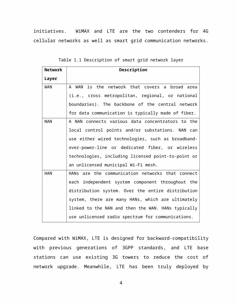
applying 4G standards in their smart grid initiatives. WiMAX and LTE are the two contenders
for 4G cellular networks as well as smart grid communication networks.
Table 1.1 Description of smart grid network layer
Network
Layer
Description
WAN A WAN is the network that covers a broad area (i.e., cross metropolitan,
regional, or national boundaries). The backbone of the central network for
data communication is typically made of fiber.
NAN A NAN connects various data concentrators to the local control points
and/or substations. NAN can use either wired technologies, such as
broadband-over-power-line or dedicated fiber, or wireless technologies,
including licensed point-to-point or an unlicensed municipal Wi-Fi mesh.
HAN HANs are the communication networks that connect each independent
system component throughout the distribution system. Over the entire
distribution system, there are many HANs, which are ultimately linked to
the NAN and then the WAN. HANs typically use unlicensed radio
spectrum for communications.
Compared with WiMAX, LTE is designed for backward-compatibility with previous
generations of 3GPP standards, and LTE base stations can use existing 3G towers to reduce
the cost of network upgrade. Meanwhile, LTE has been truly deployed by Internet Service
Provider (ISP) in Canada, United States, and other countries [6]. The Canadian government
has even allocated a 30MHz frequency spectrum in 1.8GHz for smart grid application [7].
Figure 1.2 shows the role of LTE in smart grid communication networks. LTE would be a key
component in the smart grid communication infrastructure for data acquisition, monitoring,
control and protection.
3

Figure 1.2 The smart grid connectivity supported by LTE
1.2 Long Term Evolution (LTE)
The term “LTE” is the abbreviation of 3GPP Long Term Evolution, which is the latest standard
for the mobile communication network [8]. 3GPP is currently the dominant specification
development group for mobile radio systems in the world. 3GPP technologies-Global System
for Mobile Communications (GSM)/Enhanced Data rates for GSM Evolution (EDGE) and
Wideband Code Division Multiple Access (WCDMA)/High Speed Packet Access (HSPA) are
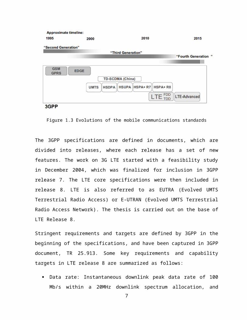
currently serving nearly 90% of the global mobile subscribers [9]. Figure 1.3 shows the
evolution track of 3GPP development. Three multiple access technologies are evident. The
‘Second Generation’, GSM, General packet radio service (GPRS) and EDGE family were based
on Time Division Multiple Access (TDMA) and Frequency Division Multiple Access (FDMA).
The ‘Third Generation’, Universal Mobile Telecommunications System (UMTS) family marked
the entry of Code Division Multiple Access (CDMA) into the 3GPP evolution track, known as
4
Wideband CDMA (WCDMA). Finally LTE adopted Orthogonal Frequency Division Multiplexing
(OFDM), which is the access technology dominating the latest evolutions of all mobile radio
standards.
Figure 1.3 Evolutions of the mobile communications standards
The 3GPP specifications are defined in documents, which are divided into releases, where
each release has a set of new features. The work on 3G LTE started with a feasibility study in
December 2004, which was finalized for inclusion in 3GPP release 7. The LTE core
specifications were then included in release 8. LTE is also referred to as EUTRA (Evolved
UMTS Terrestrial Radio Access) or E-UTRAN (Evolved UMTS Terrestrial Radio Access
Network). The thesis is carried out on the base of LTE Release 8.
Stringent requirements and targets are defined by 3GPP in the beginning of the
specifications, and have been captured in 3GPP document, TR 25.913. Some key
requirements and capability targets in LTE release 8 are summarized as follows:
Data rate: Instantaneous downlink peak data rate of 100 Mb/s within a 20MHz
downlink spectrum allocation, and uplink peak data rate of 50 Mb/s within a 20 MHz
uplink spectrum allocation.
5

Spectrum efficiency: In a loaded network, target for downlink average user
throughput per MHz is 3-4 times, and for uplink is 2-3 times better than release 6.
Latency: The one-way transmission time from the user to the server shall be less than
5 msec.
Spectrum allocation: Operation in paired spectrum (e.g., Frequency Division Duplex
(FDD) mode) and unpaired spectrum (e.g., Time Division Duplex (TDD) mode) is
possible.
Bandwidth: Saleable bandwidths of 5, 10, 15, 20 MHz shall be supported in both the
uplink and downlink.
Interworking: Interworking with existing UMTS Terrestrial Radio Access Network
(UTRAN) systems and non-3GPP systems shall be ensured.
Coverage: Throughput, spectrum efficiency and mobility targets above should met
for 5km cells, and with a slight degradation for 30km cells.
User capacity: At least 200 users per cell should be supported in an active state for
spectrum allocations up to 5MHz.
The LTE, as one of the latest steps in an advancing series of mobile telecommunications
systems, can be seen to provide a further evolution of functionality, increased speed and
improved performance comparing to the third generation systems. The specifications of four
popular technologies published by 3GPP at various times are illustrated in Table 1.2.
Table 1.2 Comparison between LTE and UMTS/3GPP 3G specifications [10]
WCDMA HSPA HSPA+ LTEMax downlink speed (bps) 384k 14M 28M 100M
Max uplink speed (bps) 128k 5.7M 11M 50MLatency (round trip time trip time) 150ms 100ms 50ms 10ms
Mote recent 3GPP release Rel. 99/4 Rel. 5/6 Rel. 7 Rel. 8Date of initial roll out 2003/4 2005/6 2008/9 2009/10Access methodology CDMA CDMA CDMA OFDMA/SC-FDMA
6

1.3 Challenges
Wireless communication nowadays is a fast-growing technology, and as the latest wireless
communication technology, LTE becomes one promising option for smart grid
communications. However, LTE is not a dedicated technology invented for smart grid. Smart
grid applications have more stringent latency requirements in WAN than other public
applications such as web.
In an ideal world, it would be possible to send data over a network and gain the same
performance as the data achieved by a circuit switched network [11]. However, the nature
of packet data means that the same channels are used for data travelling to and from a
variety of different sources and end devices. Latency is a measure of the time that it takes
for data from the source to the destination of the network, and is critical for applications
that use real-time communications. Latency comprises the length of time that a data
package takes from the sender to the receiver. A loss or an excessive latency of the critical
data, such as control messages or exceptional messages, may delay the power
measurements and control, which may lead to severe economic and social consequences.
Therefore, Quality of Service (QoS) mechanisms need to be deployed to guarantee the
reliable and prompt delivery of critical data. In smart grid communication networks, an
excessive latency of the critical data may delay the power restoration, which may lead to
severe economic and social consequences. Reducing latency becomes one of significant
challenge in smart grid communication networks.
LTE uplink scheduler is a key component for LTE communication. The algorithm of scheduler
determines the performance of LTE processing time. Because the 3GPP LTE does not define a
specific scheduling algorithm, the LTE scheduling becomes a hot topic. A large number of
researchers are working on LTE scheduler, but few researchers focus on the LTE for smart
grid communications. In the next generation smart grid network, LTE will be implemented
into WAN and NAN. In order to achieve the high demand of smart grid applications, it is
necessary to propose a proper LTE scheduling algorithm specified in smart grid network. An
optimal LTE network establishes the foundation for an advanced robust smart grid system.
7
In the multi-cell wireless network, how to balance the load between the neighboring cells is
also a critical issue for LTE. Even though LTE has a better network performance compared to
other wireless technologies, a low-efficiency traffic distribution would degrade the network
performance. An imbalanced multi-cell LTE network would suffer from the increased delay,
the decreased network throughput, or even the packet drops. Therefore, the LTE multi-cell
load balancing problem needs to be considered.
1.4 Existing Work
For the usage of LTE in smart grid network, the researcher started to propose the next-
generation smart grid framework using LTE as WAN or NAN when the LTE specification was
published by 3GPP [12] [13]. Up to now, the LTE infrastructure and next-generation smart
grid is becoming complete. Some countries, including Canada [7], have been planning to
incorporate the LTE into the industry for several years. At the same time, some governments
and corporations are investigating the feasibility of using the LTE in smart grid networks [5].
Regarding works on LTE uplink scheduler, many scheduling algorithms have been proposed.
The research interests mostly concentrate on how to maximize the performance and how to
keep the fairness among different users or different applications. The research
methodologies are divided into three types: Best Effort Schedulers [14] [15] [16] [17], QoS-
based Schedulers [18] [19] [20] and Power-optimizing Schedulers [21] [22], depending on
different objectives. The details of the three categories of schedulers are described in
Section 2.2. Most of the existing work aims to optimize the scheduling algorithm for normal
applications, such as web, video and audio. The LTE scheduling for smart grid is less
explored.
LTE load balancing among multiple cells is also important in research and standardization.
The optimization goal is to find the optimal handover operations between the overloaded
cell and a possible target cell. The existing methods [23] [24] [25] [26] aim to maximize user
satisfaction by satisfying the hand-over trigger requirements and reducing the traffic
8

congestion. Also, the researchers are trying to reduce the load balancing complexity and
overhead of the solution to the problem.
1.5 Thesis Contributions
The contributions of this work are summarized as follows:
We investigate the LTE uplink scheduling problem in smart grid WAN and propose a
novel LTE uplink scheduling algorithm to optimize the allocation of resource blocks
(RBs) in the LTE evolved NodeB (eNB or eNodeB) to provide scheduling time
guarantee to different class of smart grid traffic. The simulation results demonstrate
that the proposed optimal scheduling scheme can use less resource blocks to satisfy
the scheduling time requirements, compared to the two existing scheduling schemes
(the Large-Metric-First scheduling scheme and the Guaranteed Bit Rate (GBR)/Non-
GBR scheduling scheme). This contribution will be presented in Chapter 3.
For multi-cell LTE network, we proposed a load balancing algorithm for smart grid
network. The experiment results in OPNET demonstrate that the proposed algorithm
can reduce the overall delay by appropriately distributing the traffic load among
multiple cells. This contribution will be presented in Chapter 4.
1.6 Organization of Thesis
This thesis consists of five chapters, which are briefly described as follows:
In Chapter 1, we present an introduction to the smart grid communication networks,
the overview of LTE, the challenge on WAN latency, the existing work to deal with
the challenge, and the contributions of our work.
In Chapter 2, we present the fundamentals of LTE, and the related work.
In Chapter 3, we study a queuing model and an LTE uplink scheduling model. Based
on the models, we analytically show the relationship between the scheduling time
9

and the resource blocks to be allocated. Then, we present the problem formulation
and propose a heuristic algorithm for the LTE uplink scheduler.
In Chapter 4, we propose a load balancing algorithm for multi-cell LTE networks.
In Chapter 5, we conclude our work and provide future research directions.
10
Chapter 2
Background
This chapter provides preliminary background information on various aspects of LTE system.
The background provided below presents the LTE system architecture and the detail
technologies at physical layer. This chapter then introduces the literature reviews on the
smart grid WAN, the LTE QoS and LTE load balancing.
2.1 Technical Overview of LTE
2.1.1 Introduction
LTE system consists of an Evolved UMTS, E-UTRAN and an Evolved Packet Core (EPC)
presented in Figure 2.1. eUTRAN is chosen as the air interface of LTE, which is simply a
network of base stations, eNB. There is no centralized intelligent controller, and the eNBs
are normally inter-connected each other by the X2-interface and towards the core network
by the S1-interface. In smart grid network, the end terminals, User Equipments (UEs), send
the data packets to the eNB via LTE radio signals. Such a connection is for a smart grid to
upload the electricity usage status or make measurements of the data.
11

To achieve high radio spectral efficiency a multicarrier approach for multiple accesses was
chosen by 3GPP. The LTE system defines Orthogonal Frequency Division Multiple Access
(OFDMA) as the access technique for the downlink communications and Single Carrier
Frequency Division Multiple Access (SC-FDMA) for the uplink. OFDMA has advantages of
robustness against multi-path fading, higher spectral efficiency and bandwidth scalability;
and SC-FDMA makes UEs energy saving. The additional crucial technique applied in LTE is
Multiple-Input-Multiple-Output (MIMO) that uses multiple transmitters and receivers to
achieve a higher bit rate and a higher coverage.
The MAC (Media Access control) layer is responsible for scheduling, which is represented
only in the UE and in the base station, leading to fast communication and decisions between
the eNB and the UE. In UMTS, the scheduling is located in the controller. An additional part
of MAC layer was added in the LTE eNB, which is responsible for the scheduling.
Figure 2.4 LTE architecture diagram
12

2.1.2 SC-FDMA and OFDMA
2.1.1.2 OFDMA
The downlink in LTE uses OFDMA for its transmission scheme. The transmitter principle in
any OFDMA system is to use narrow, mutually orthogonal sub-carriers. The sub-carrier
spacing is 15 kHz regardless of the total transmission bandwidth in LTE system. Different
subcarriers are grouped together to form a sub-channel that serves as the basic unit of data
transmission. The main reasons why OFDMA was selected as the basic transmission scheme
for LTE are its high spectral efficiency, low-complexity implementation, and the ability to
easily support advanced features such as frequency selective scheduling, MIMO
transmission, and interference coordination. Figure 2.2 shows the resource allocation
illustration for LTE downlink.
Figure 2.2 The resource allocation illustration for LTE downlink
The practical implementation of an OFDMA system is based on digital technology and more
specifically on the use of Discrete Fourier Transform (DFT) and Inverse Discrete Fourier
Transform (IDFT) to move between time and frequency domain representations. A basic
block diagram illustrating OFDMA signal generation for one OFDM symbol is shown in Figure
2.3. Data symbols from different users are mapped to different subcarriers depending on the
frequency bands assigned to those users. This is done in the frequency domain. The
13
information is then subjected to an inverse fast Fourier transform (IFFT) to convert the
frequency-domain subcarriers into time-domain signals. A cyclic prefix is then added, and
the signal is ready for transmission. Note that the basic transmission unit for data is a sub-
frame that spans multiple OFDM symbols. At the receiver, the reverse operation is
performed. The cyclic prefix is removed, and then the time-domain signal is subjected to a
fast Fourier transform (FFT) so that the modulation symbols on each subcarrier can be
extracted. Each user then extracts the frequency resource units corresponding to his
assigned subcarriers. Equalization is performed and the data is passed onward for decoding.
Figure 2.3 Block diagram for OFDMA
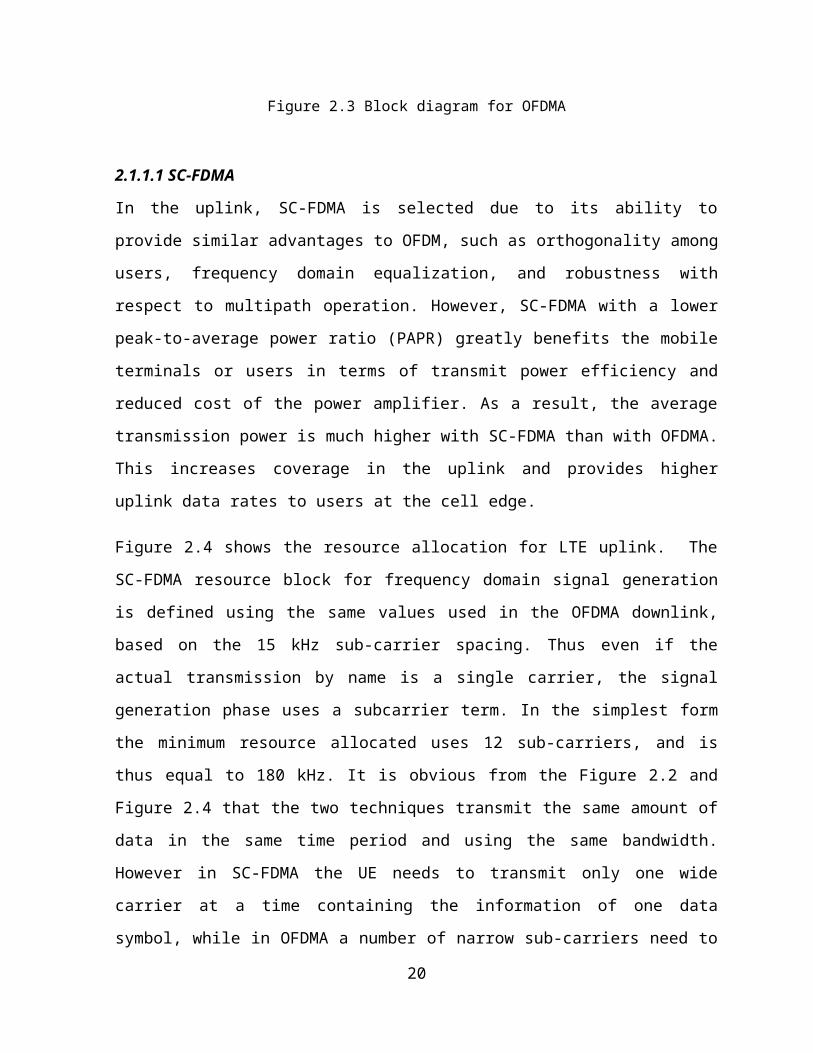
2.1.1.1 SC-FDMA
In the uplink, SC-FDMA is selected due to its ability to provide similar advantages to OFDM,
such as orthogonality among users, frequency domain equalization, and robustness with
respect to multipath operation. However, SC-FDMA with a lower peak-to-average power
ratio (PAPR) greatly benefits the mobile terminals or users in terms of transmit power
14

efficiency and reduced cost of the power amplifier. As a result, the average transmission
power is much higher with SC-FDMA than with OFDMA. This increases coverage in the uplink
and provides higher uplink data rates to users at the cell edge.
Figure 2.4 shows the resource allocation for LTE uplink. The SC-FDMA resource block for
frequency domain signal generation is defined using the same values used in the OFDMA
downlink, based on the 15 kHz sub-carrier spacing. Thus even if the actual transmission by
name is a single carrier, the signal generation phase uses a subcarrier term. In the simplest
form the minimum resource allocated uses 12 sub-carriers, and is thus equal to 180 kHz. It is
obvious from the Figure 2.2 and Figure 2.4 that the two techniques transmit the same
amount of data in the same time period and using the same bandwidth. However in SC-
FDMA the UE needs to transmit only one wide carrier at a time containing the information of
one data symbol, while in OFDMA a number of narrow sub-carriers need to be transmitted
at each time period. Thus the SC-FDMA technique is more power efficient.
Figure 2.4 Illustration of resource allocation for LTE uplink
Frequency domain generation of the signal is shown in Figure 2.5. The frequency domain
generation of the signal adds the OFDMA property of good spectral waveform in contrast to
time domain signal generation with a regular Quadrature Amplitude Modulation (QAM)
modulator. Thus the need for guard bands between different users can be avoided, similar
15

to the downlink OFDMA principle. As in an OFDMA system, a cyclic prefix is also added
periodically, but not after each symbol as the symbol rate is faster in the time domain than
in OFDMA to the transmission to prevent inter-symbol interference and to simplify the
receiver design. The receiver still needs to deal with inter-symbol interference as the cyclic
prefix now prevents inter-symbol interference between a block of symbols, and thus there
will still be inter-symbol interference between the cyclic prefixes. The receiver will thus run
the equalizer for a block of symbols until reaching the cyclic prefix that prevents further
propagation of the inter-symbol interference.
Figure 2.5 Block diagram for SC-FDMA
2.1.1.3MIMO
MIMO is used in LTE to improve the performance of the system. This technology provides
LTE with the ability to further improve its data throughput and spectral efficiency above that
obtained by the use of OFDM.
For the uplink from the mobile terminal to the base station, a scheme called Multi-User
MIMO is employed. In Multi-user MIMO, the base station requires multiple antennas, while
16

the mobiles terminal only needs one transmit antenna, thus considerably reducing the cost.
In operation, multiple mobile terminals may transmit simultaneously on the same channel or
channels, but they do not cause interference to each other because mutually orthogonal
pilot patterns are used. This technique is also referred to as Spatial Domain Multiple Access
(SDMA).
For the downlink, a configuration of two transmit antennas at the base station and two
receive antennas on the mobile terminal is used as baseline, although configurations with
four antennas are also being considered.
2.1.3 Control signaling for uplink scheduling
Channel State Information (CSI) refers to the SINR measurement of the channel properties
on the uplink direction between the UE and eNodeB. This information describes how a signal
propagates from the transmitter to the receiver and represents the combined effect of, for
example, scattering, fading, and power decay with distance. The CSI makes it possible to
adapt transmissions to current channel conditions, which is crucial for achieving reliable
communication with high data rates in multi-antenna systems.
Buffer Status Reporting (BSR) refers to the 3GPP standardized reporting mechanism that a
UE uses to send its buffer information to the eNodeB [27]. BSR mechanism plays an
important role in QoS provisioning. The scheduler can get a status report on how much data
awaiting transmission at the UE's uplink buffer.
2.2 Literature Review
2.2.1 Related work on smart grid WAN
Traditionally, the communication infrastructure of a power system consists of supervisory
control and data acquisition (SCADA) systems with dedicated communication channels
17

between the control center and a WAN [28]. The SCADA systems connect all the major
power system operational facilities, including the central generating stations, the
transmission grid substations and the primary distribution substations to the System Control
Centre. The WAN is used for corporate business and market operations. These form the core
communication networks of the traditional power systems. However, in the Smart Grid, it is
expected that these two elements of communication infrastructure will merge into a Utility
WAN.
Many investigations have been conducted in the area of smart grid WAN communications. In
[12] [13], the authors presented the background and motivation of communication
infrastructure in smart grid systems, and summarized the major requirements that smart
grid communications must meet. The communication is characterized by the fact that most
of the interactions must take place in real time, with a hard time bound, since a smart grid
system might have over millions of consumers and devices. For real-time sensing/metering
purposes, reading messages need to be transmitted within a very short time frame. For
instance, the maximum allowed time is in the range of 12-20 ms (milliseconds), depending
on the type of protection scheme which requires that the disconnection of fault current
should be within approximately 100 ms. Power System Control signals mainly include
supervisory control of the power process on the secondary or higher levels. Measured values
of these systems must not be older than 15 seconds, when arriving at the control center.
Breaking information shall arrive no later than 2 seconds after the emergency event has
occurred [29].
The authors in [30] addressed critical issues on smart grid technologies primarily in terms of
information and communication technology issues and opportunities. Different
communications technologies supported by two main communications media, i.e., wired and
wireless, can be used for data transmission between smart meters and electric utilities.
Wireless communications have some advantages over wired technologies in certain
instances, such as low-cost infrastructure and ease of connection to difficult or unreachable
areas. But the technological choice that fits one environment may not be suitable for the
18

other. Therefore, the authors briefly explained several popular wireless technologies, such as
ZigBee, GPRS, HSPA+, WiMAX, etc. in terms of their advantages and disadvantages.
The feasibility of applying LTE to smart grid communication networks was studied in [5]. The
document released by the National Institute of Standard and Technologies (NIST) [31],
analyzed the traffic distributions of Distribution Automation (DA) networks and concluded
that the major technique challenge for the LTE DA network is the tightly coupled Radio
Access Network (RAN) latency constraint of 100ms and reliability requirement of 10 -3. For
the latency requirement, the bandwidth is reserved only for the low-duty-cycle field devices
to mitigate queuing delays and decrease scheduling delay by maintaining all field devices in a
Radio Resource Control-CONNECTED state. For the reliability, the simulation results show
that the reliability requirement can be satisfied with 4×2 closed-loop Single User-MIMO (SU-
MIMO) system in downlink, and with 1×4 system in uplink, respectively.
In [32], the authors designed communication network architecture for smart grid based on
broadband wireless communication technology, such as 3G, LTE and LTE-Advanced. As the
emergency communication has a critical requirement of wireless communication technology
in the smart grid, a solution for emergency communications is designed based on LTE
technology. In the solution, the Time-division duplex mode is used, and SCFDMA uplink is
configured with more time slot resources than OFDMA downlink.
2.2.2 Related work on LTE QoS
This section provides a survey on the existing work on LTE schedulers in the literature. Based
on the schedulers’ objective, the schedulers can be categorized in to three classes:
1. Best Effort Schedulers
2. QoS-Based Schedulers
3. Power-Optimized Schedulers
19

Best Effort Schedulers
Most of the existing work for UE uplink scheduling focused on maximizing performance
metrics such as data throughput and fairness. Best-effort schedulers were designed to
maximize the utilization of the radio resources and/or fairness of resource sharing among
UEs.
The work in [14] proposed two new scheduling algorithms considering both the channel
contiguity constraint and the latency constraint. The first greedy algorithm called a Low Cost-
delay (LC-delay) algorithm, schedules each resource block to a user in a way that minimizes
allowed delay and guarantees a maximum throughput for each user. It goes through each
block, one after the other, and assigns it to a user, taking into account the adjacency
resource block constraints, if the minimum delay and maximum throughput requirements
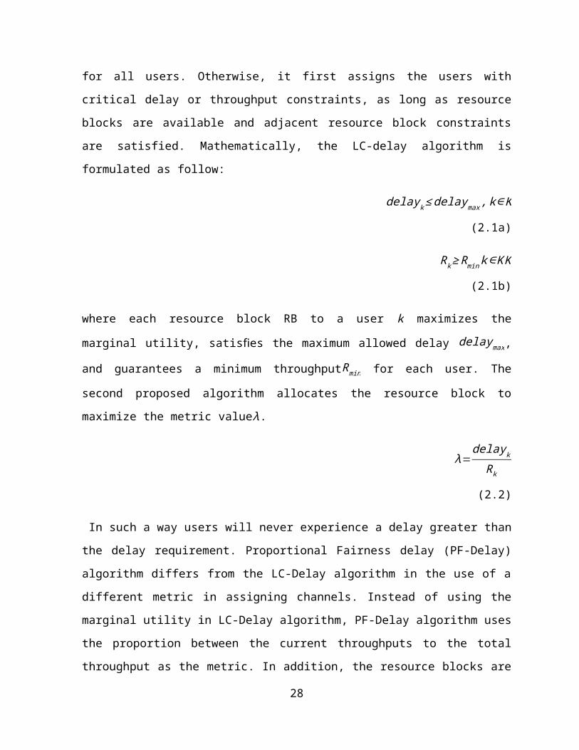
are satisfied for all users. Otherwise, it first assigns the users with critical delay or
throughput constraints, as long as resource blocks are available and adjacent resource block
constraints are satisfied. Mathematically, the LC-delay algorithm is formulated as follow:
delay k≤delaymax , k∈K (2.1a)
Rk ≥Rmink∈K K (2.1b)
where each resource block RB to a user k maximizes the marginal utility, satisfies the
maximum allowed delay delaymax, and guarantees a minimum throughputRmin for each user.
The second proposed algorithm allocates the resource block to maximize the metric valueλ.
λ=delaykRk
(2.2)
In such a way users will never experience a delay greater than the delay requirement.
Proportional Fairness delay (PF-Delay) algorithm differs from the LC-Delay algorithm in the
use of a different metric in assigning channels. Instead of using the marginal utility in LC-
Delay algorithm, PF-Delay algorithm uses the proportion between the current throughputs
to the total throughput as the metric. In addition, the resource blocks are not assigned in
20

order, but with respect to the user with the most critical delay requirement, under the
condition that the user has a reasonable utility value.
The authors in [15] investigated the performance of frequency and time domain scheduling
in LTE uplink, particularly the performance impact of various scheduling metrics aiming to
achieve proportional fairness in throughput or resource allocation. Three different metrics
were presented in this paper, which is shown in Table 2.1. In the table, T̂ ( i , n , k ) is the
estimated achievable throughput for UE i at scheduling interval n on PRB k; T ( i , n ) is the past
averaged acknowledged throughput for UE i, at scheduling interval n. For PF-SINR definition,
SINRCSI (i , n , k) represents CSI SINR measured at the BS for UE i, at scheduling interval n, on
PRB k; SINRCSI , w(i , n) representes wideband CSI SINR measured at the BS for UE t at
scheduling interval n. T w ( i , n ) in PF-TTW is the estimated wideband achievable throughput
for UE i, at scheduling interval n. Based on the properties exhibited by the metrics, a
throughput-based Proportional Fairness (PF) metric in time domain combined with an SINR-
based PF metric in frequency domain is shown to be particularly effective. Results show that
such combination is able to achieve a gain of approximately 21% in average cell throughput
and 37.5% in outage user throughput compared to the combination of PF both in the time
domain and in the frequency domain.
The authors in [16] investigated the latency caused by LTE communication networks, and
established an empirical mathematical model for the distribution of the latency. The
limitations of the current LTE were discussed, and a new scheduler with a new utility
function was designed, which is shown below
λ=W p+Ppf (2.3)
where W p is the weight for the UE in the smart grid, which is obtain as
W p=α 1r+α 2l+α3q (2.4)
21

with α 1+α2+α3=1. r representing constant data updating rates; l representing equivalent
data packets lengths; and q representing approximately invariant channel qualities. Ppf is
given by the traditional LTE scheduling algorithm:
Ppf=(CI ) [R (t)]−1 (2.5)
Here, C /I represents channel condition and R(t ) is the throughput within the time interval.
Table 2.3 Metric definitions
Metric name Definition
PF T̂ (i , n , k )T (i , n )
PF-SINR SINRCSI (i , n , k )SINRCSI , w(i , n)
PF-TTW T̂ (i , n , k )T w ( i , n )
In [17], a game theoretical formulation is derived where the scheduling problem is
represented as a Nash bargaining game. It was shown in the simulations that the
maximization of the sum throughput leads to a higher cell throughput, while considering the
logarithm of throughput as a utility function ensures proportional fairness, and thus
constitutes a trade-off between throughput and fairness.
QoS-Based Schedulers
Bandwidth and QoS Aware (BQA) scheduler was proposed in [18], in which QoS provision is
guaranteed to the UEs. It maximizes the cell throughput by giving priority to UEs with better
channel conditions. Multi-bearer UEs are supported by the scheduler. The scheduler is time
and frequency domain decoupled. Resource allocation is performed with bandwidth
flexibility, contiguity constraint of subcarriers and UE buffer size consideration.
22

QoS-based scheduler was proposed in [19], where the authors proposed Guaranteed Bit
Rate/Proportional Fairness (GBR/PF) LTE uplink scheduler accompanied by a proposal for
QoS-aware algorithm. The proposed packet scheduling algorithm explicitly decouples the
scheduling process into time domain and frequency domain scheduling. QoS provisioning is
achieved by introducing a term that is a function of the UE's average throughput normalized
by its GBR. The introduced GBR-based term is used in time domain to prioritize UEs, and is
also used as part of the frequency domain metric. The study showed that the proposed
scheduler can provide better support for QoS traffic streams, especially the ones with the
low GBR rate, such as Voice over IP (VoIP) services.
A new uplink scheduling algorithm with a new utility function were used in [20]. The
proposed uplink scheduling algorithm can distinguish between inter-class and intra-class
prioritization of the multiplexed traffic for the LTE network. The results obtained by the new
algorithm showed the effectiveness and strength of handling traffic priority and fairness.
Moreover the interesting opportunity cost function has been used to adjust the network
operator’s revenue loss. By adjusting different parameters, the scheduler can achieve its
desired level of inter-class and intra-class prioritization with fairness.
Power-Optimized Schedulers
The goal of Power-optimized schedulers aims to reduce power consumption of mobile UEs
on wireless transmissions. A scheduler in this category first acquires some QoS aspects of the
traffic flows transmitted on the LTE uplink, such as packet delay budget or GBR
requirements. The schedulers then perform some algorithmic decisions to reduce the
transmission power of the UE under the constraints of QoS requirements.
Power-optimized schedulers for LTE were not investigated thoroughly in the literature. Two
scheduling algorithms can be categorized into this class. The first algorithm was presented in
[21], where the authors introduced power minimized schedulers based on queuing delay
constraints. The idea is to make significant savings in the UE’s transmission power under
satisfying the UE’s GBR requirements premise.
23
Another algorithm for power-based LTE uplink scheduling was proposed in [22]. The
scheduler first creates a matrix to represents all the possible allocation patterns possible of
uplink resource blocks under the contiguity constraint. The scheduler then calculates the
power needed for each possible allocation pattern for each UE. Finally, the scheduler
performs a greedy-based search algorithm to find the UE-PRB allocation pattern that
minimizes the power consumption on each UE under the GBR requirements.
2.2.3 Related work on LTE load balancing
The load balancing algorithm in the wireless cellular networks aims at finding the optimum
handover operations between the overloaded cell and a possible target cell. This objective
assures that the users that are handed over to the target cell will improve the network
improvement in terms of the latency, and make the whole network more efficient.
Many researchers are working on LTE load balancing. An early paper, [23], presented a
mathematical framework for quantitative investigations of self-optimizing wireless networks
for LTE system. The SINR ratio distribution, the number of satisfied users and energy
efficiency were considered in presented models. A simple self-optimizing network algorithm
was described in this paper, which adjusts the cell-specific handover thresholds for the sake
of load balancing. This algorithm has been applied to a simple scenario where the users are
concentrated in particular areas in the network. The number of unsatisfied users was
significantly reduced compared with the homogenous solution.
In [24], the authors proposed a handover offset based load balancing algorithm using the
parameter “cell specific offset” to force users to handover from the overload eNB to the
target eNB, which improved the earlier proposed LTE load balancing algorithm in [23]. The
main goal of the proposed algorithm is to find the optimum handover offset that allows the
maximum number of users to change cell without any rejections by admission control
mechanism at target eNB side.
24

In [25], a directional cell breathing based-reactive congestion control heuristic algorithm was
proposed, where the coverage area of a cell sector can dynamically be extended towards a
nearby loaded sector or shrunk towards cell center for a loaded sector.
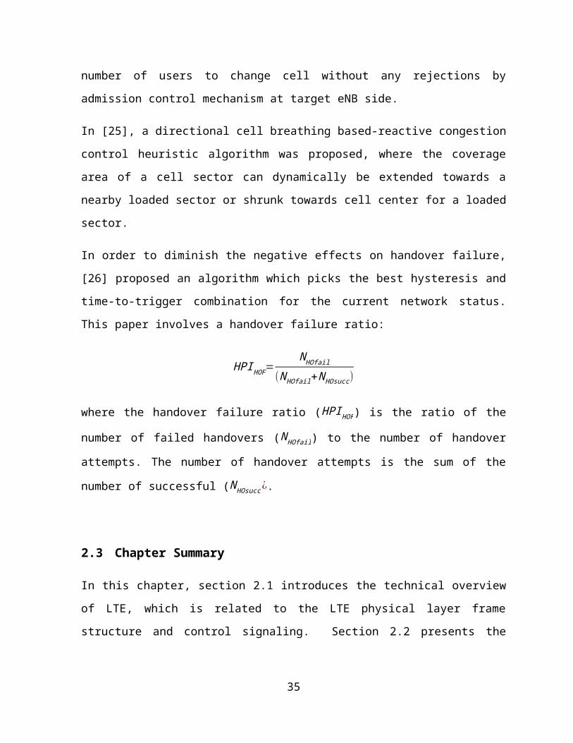
In order to diminish the negative effects on handover failure, [26] proposed an algorithm
which picks the best hysteresis and time-to-trigger combination for the current network
status. This paper involves a handover failure ratio:
HPI HOF=N HOfail
(N HOfail+N HOsucc)
where the handover failure ratio (HPI HOF) is the ratio of the number of failed handovers (
N HOfail) to the number of handover attempts. The number of handover attempts is the sum
of the number of successful (N HOsucc ¿.
2.3 Chapter Summary
In this chapter, section 2.1 introduces the technical overview of LTE, which is related to the
LTE physical layer frame structure and control signaling. Section 2.2 presents the literature
reviews of the smart grid WAN, the LTE QoS and the LTE load balancing.
25

Chapter 3
LTE Uplink Scheduling Algorithm
for Smart Grid
This chapter presents a new LTE uplink scheduling algorithm for Smart Grid communications.
First, a queuing model and an LTE uplink scheduling model are presented. Next, a
lightweight heuristic algorithm is proposed to obtain the optimal allocation of resource
blocks for each class of smart grid traffic. Finally, the simulation results are presented to
evaluate the performance of the proposed algorithm.
3.1 Introduction
In many countries, data fiber network, synchronous optical network (SONET), SCADA
network, etc., are being deployed in the current smart grid WAN. However, the smart grid
WAN is still dissatisfactory in some aspects, such as lack of common backhaul medium for
data communication. Furthermore, future demands including PHEV and CES require reliable
two-way communications and interactivities that traditional network systems cannot
provide. Therefore, the traditional communication architecture needs to be upgraded
urgently, or even replaced by a more advanced communication technology.
Currently, the latest 4G wireless technology, the 3GPP LTE, is the promising option for smart
grid WANs. There are several kinds of technologies available for smart grid WAN, such as
LTE, WiMAX, etc. Compared with other technologies, LTE provides excellent performance in
26
terms of higher data rates, lower latency and larger coverage. Moreover, as a wireless
communication technology, LTE supplies extra flexibility than the wired communications.
However, LTE is not a technology invented for smart grid. Smart grid applications have
special QoS requirements such as more stringent latency requirements in WAN than other
public applications such as web. An excessive delay of the critical data may delay the power
restoration, which may lead to severe economic and social consequences. Reducing latency
or end-to-end delay becomes one major challenge in smart grid communication networks.
In this chapter, we study the LTE uplink scheduling problem in smart grid WAN. Particularly,
we optimize the allocation of RBs in the LTE eNB in LTE, to provide scheduling time
guarantee to different class of smart grid traffic.
3.2 System Models
3.2.1 Queuing Model
According to the requirements, the data in the smart grid can be categorized into different
classes. For example, data on remote workforce is classified into low-priority class, while the
control data from the control center and exception messages such as the outage
notifications are classified into the critical class. The queuing model is used to study the
scheduling time of each class and the total scheduling time for the LTE scheduler. The
queuing model consisting of several queues and one scheduler is involved in our study. The
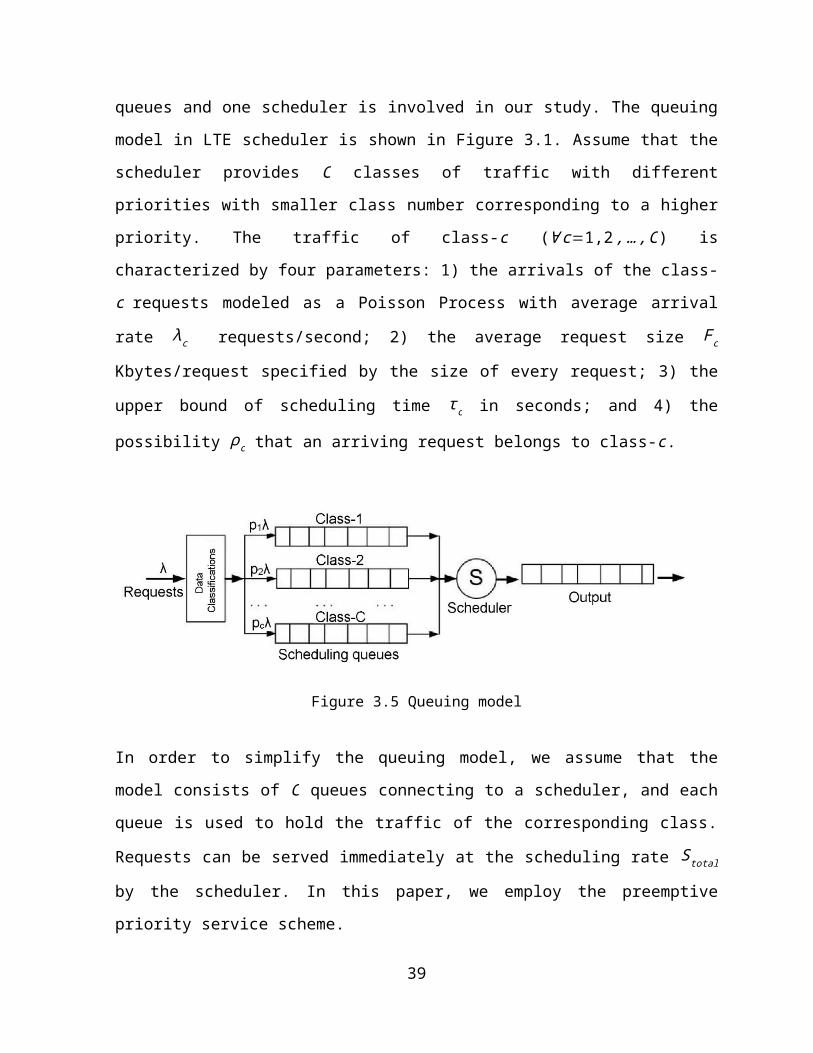
queuing model in LTE scheduler is shown in Figure 3.1. Assume that the scheduler provides
C classes of traffic with different priorities with smaller class number corresponding to a
higher priority. The traffic of class-c (∀ c=1,2 ,…,C) is characterized by four parameters: 1)
the arrivals of the class-c requests modeled as a Poisson Process with average arrival rate λc
requests/second; 2) the average request size F c Kbytes/request specified by the size of
every request; 3) the upper bound of scheduling time τ c in seconds; and 4) the possibility ρc
that an arriving request belongs to class-c.
27

Figure 3.5 Queuing model
In order to simplify the queuing model, we assume that the model consists of C queues
connecting to a scheduler, and each queue is used to hold the traffic of the corresponding
class. Requests can be served immediately at the scheduling rate Stotal by the scheduler. In
this paper, we employ the preemptive priority service scheme.
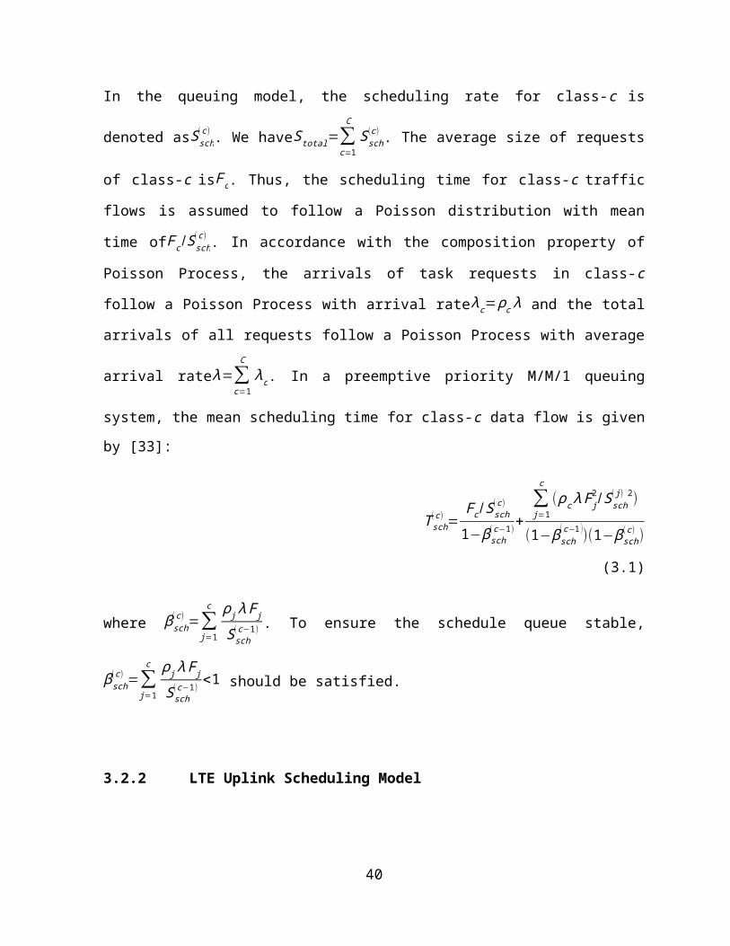
In the queuing model, the scheduling rate for class-c is denoted asSsch(c) . We haveStotal=∑
c=1
C
Ssch(c)
. The average size of requests of class-c isF c. Thus, the scheduling time for class-c traffic
flows is assumed to follow a Poisson distribution with mean time ofF c /Ssch(c) . In accordance
with the composition property of Poisson Process, the arrivals of task requests in class-c
follow a Poisson Process with arrival rateλc=ρc λ and the total arrivals of all requests follow
a Poisson Process with average arrival rateλ=∑c=1
C
λc. In a preemptive priority M/M/1 queuing
system, the mean scheduling time for class-c data flow is given by [33]:
T sch(c)=
Fc / Ssch(c)
1−βsch(c−1) +
∑j=1
c
(ρc λ F j2/Ssch
( j) 2)
(1−βsch( c−1 ))(1−β sch
(c) ) (3.1)
where βsch(c)=∑
j=1
c ρ j λF j
Ssch(c−1) . To ensure the schedule queue stable,βsch
(c)=∑j=1
c ρ j λF j
Ssch(c−1) <1 should be
satisfied.
28

3.2.2 LTE Uplink Scheduling Model
The LTE uplink scheduler is located at the base station in LTE. The minimum transmission
unit of LTE scheduler is known as a resource block. The radio resource that is available in the
uplink LTE system is defined in both frequency and time domains. In the frequency domain,
each RB consists of 12 consecutive subcarriers and in the time domain it is made up of one
time slot of 0.5ms duration. Each 1ms Transmission Time Interval (TTI) consists of 2 slots,
and a subframe is defined as 10 TTIs. At each TTI, multiple RBs can be assigned to a number
of users with different classes; each resource block however can be assigned to at most one
user. The LTE scheduler has B MHz bandwidth, divided into N RBs. Table 3.1 shows the
channel bandwidth for a given quantity of resource blocks. We assume that the scheduler is
capable of assigning RBs arbitrarily to all users and each RB n has a bandwidth ofB/N . Let
n={1,2 ,…,N } denotes the RB index set. For simplicity, we suppose that uniform power
allocation across all subcarrier.
Table 3.4 Number of resource blocks for different LTE bandwidths
Channelbandwidth [MHz] 1.4 3 5 10 15 20
Number of resource blocks 6 15 25 50 75 100
29

Figure 3.6 3GPP LTE radio frame structure
We define a variablexc to indicate the number of resource blocks assigned to class-c traffic
flows. According to Shannon-Hartley theory, for uplink direction, the maximum uplink
channel throughput of class-c in the SC-FDMA multiplex can be expressed as [34] [35]:
Ssch(c)=xc
BN
log2(1+SINRn(c)) (3.2)
where SINRn(c ) is the average Signal to Interference and Noise Ratio (SINR) for the RB n at the
transmitter. The LTE standard provides reporting mechanisms (CSI) to provide the packet
scheduler with valuable information about the cellular environment that can assist in
increasing the scheduling operation in the uplink [36].
30

In the situation, we can define SINRn(c) and evaluate for every class in each time duration,
presented in [37]
SINRn(c)=
ψk / Lx(u )( p⃗u)
∑k ≠ x(u)
ψ k∙ ρk /Lk ( p⃗u)+N (3.3)
where ψk represents the transmit power of the sender for cell k at time t . A user u is
located at position p⃗u. A function x (u) means that user u is served by the cell k=x (u). Each
user is connected exactly to a single cell. Lx (u )( p⃗u) and Lk ( p⃗u) donate the path loss defined
by the positions of useru (taking into account the distance between them) to the currently
serving cell and other interference cell, respectively.
Therefore, the total scheduling rate for the LTE uplink scheduling is given by:
Stotal=∑c=1
C
xcBN
log2(1+SNRn(c)) (3.6)
Based on the above analysis, we can formulate the mean scheduling time for processing
class-c traffic as follows:
T sch(c ) =
F c/ (x¿¿ cBN
log2 (1+SNRn(c ) ))
1−∑j=1
c−1 λ j F j
x jBN
log2 (1+SNRn( j ) )
+¿¿
∑j=1
c
¿¿¿¿¿ (3.7)
∀ c=1 ,2,…,C ,
Therefore, the total scheduling time for processing all requests is formulated as:
T total=∑c=1
C λcλT sch
(c) (3.8)
31
3.3 Problem Formulation
We formulate the allocated resource blocks minimization problem based on the queuing
model and the LTE uplink scheduling model, aiming to minimize the total number of the
allocated resource blocks while satisfying the scheduling time constrain for each class of
traffic. The problem of resource block minimization can be written as:
Minimize{x c}
xc (3.9a)
Subject to
xc≤ N ,∀ c=1 ,2 ,…,C , (3.9b)
∑c=1
C
xc ≤N , (3.9c)
∑j=1
c ρ j λ F j
Ssch( c−1 ) <1 , (3.9d)
λcFc<Ssch(c ) , ∀ c=1 ,2 ,…,C , (3.9e)
T sch(c) <τc ,∀ c=1 ,2 ,…,C , (3.9f)
where Eq.(3.9b) indicates that the resource blocks assigned to class-c must be less than or
equal to the total number of resource blocks, Eq. (3.9c) declares that the number of
allocated resource blocks is less than the total number of resource blocks, Eq. (3.9d)
presents the inequality to ensure the queuing model stability, Eq. (3.9e) shows the
relationship between the arrival rate and the scheduling rate for class-c, and τ c in Eq. (3.9f)
is the upper bound of the scheduling time for class-c service which is pre-defined according
to the QoS requirements for different classes.
32

3.4 The proposed LTE Uplink Scheduling Algorithm
Although global searching to find the solution of the minimum resource blocks could be
feasible, such method is inefficient. Therefore, we propose a heuristic scheme to obtain a
sub-optimal solution. The proposed heuristic scheme dynamically decides the number of
resource blocks allocated to each class in each TTI. Algorithm 1 describes the proposed
heuristic scheme in details. In each TTI, the eNB scheduler captures the Buffer Status Report
and Channel State Information from the user equipments, and calculates SINR values. The
principle of the allocation is to assign RBs in sequential order from the higher-priority classes
to lower-priority classes. The initial number of resource blocks to be allocated for class-c, x, is set to 1. Next, the scheduler calculates the scheduling time T sch
(c) using Eq. (3.7) and
compares it with the scheduling time requirementτ c,. If the value of calculation is larger than
the requirement, the value x is increased by 1. The scheduler keeps increasing the resource
blocks, until the scheduling time T sch(c) meets the requirement. When the calculated value
becomes smaller thanτ c, xc is determined and the scheduler allocates xc resource blocks to
the class-c traffic flows. Then the scheduler begins to process the next class traffic flows.
Once the allocation is complete, the system updates all the relevant parameters.
Note that the system adjusts itself in order to match the QoS target. The proposed allocation
scheme aims to allocate minimum RBs. Our proposed heuristic can guarantee each class of
traffic is allocated the minimum RBs. If any of the class obtains one less resource block, this
class of traffic cannot satisfy the scheduling time requirements.
33

Algorithm 1 Proposed LTE uplink scheduling algorithm
1: Let N be the set of resource blocks. 2: Let n be the index of resource blocks. 3: for n=1 to N do 4: Calculate SINR value of each resource block 5: end for 6: n=0 7: for c=1 to C do 8: x←1 9: while n<N do10: Calculate T x
(c)
11: if T x(c)<τ c and ∑
j=1
c ρ j λ F j
Ssch( c−1 ) <1 then
12: if n+xc<N then13: xc←x 14: Assign xc resource blocks for the class-c data flow15: n←n+xc16: else17: xc←(N−n)18: Assign xc resource blocks for the class-c data flow19: Stop allocation until next TTI20: end if21: else22: x← x+1 23: end if24: end while25: end for
3.5 Simulations
3.5.1 Simulation Setting
In this section, we perform LTE uplink simulations to evaluate the performance of the
propose scheduling scheme.
34

Table 3.2 summarizes the parameter settings of smart grid traffic. All traffic is divided into
three classes. Class-1 traffic has the highest priority, including the exception messages and
alarms. Class-2 contains the control messages which are not as critical as those in class-1.
The normal operation traffic is classified into class-3. The total arrival rate of the incoming
traffic is set in the range of 100-300 requests/second. The other simulation configurations
can be seen in Table 3.3. We evaluate the number of RBs allocated for different classes in
different scheduling algorithms as well as the performance of the algorithms in terms of
scheduling time.
We compare the performances among three scheduling schemes: 1) our proposed
scheduling, 2) a Large-Metric-First scheduling scheme [16], and 3) the Guaranteed Bit Rate
(GBR)/Non-GBR scheduling scheme [38]. The Large-Metric-First scheduling scheme is
determined by a utility function for UEs, which is given by λ = WP + PPF , where WP is the
weight for UEs in the smart grid communication network and PPF is given by traditional LTE
scheduling proportional fair (PF) algorithm. The GBR/Non-GBR scheduling represents a
guaranteed minimum bit rate requested by an application. In LTE, the GBR bearers and non-
GBR bearers can be provided. Of these, the GBR bearers are typically used for applications
such as exception messages and control messages, with an associated GBR value; higher bit
rates can be allowed if resources are available. Non-GBR bearers do not guarantee any
particular bit rate, which usually are used for the normal operation applications. All
simulations have been conducted with the parameters described in Section 3.5.2.
Table 3.5 Parameter settings of smart grid traffic
Service class 1 2 3
Percentage of arrival rate 20% 30% 50%
Average requests size (bytes) 30k 50k 700k
Upper bound of scheduling time (sec) 0.001 0.003 0.007
35

Table 3.6 Major simulation parameters of LTE
Parameter Setting
System bandwidth 10MHz
Number of RBs 50
Number of subcarriers per RB 12
RB bandwidth 180KHz
Transmission time interval 1ms
Transmission power 125mW
Noise power per Hz 160dBm
Traffic arrival model Poisson
3.5.2 Simulation Results
Figure 3.3 shows the number of resource blocks for different classes in proposed LTE
scheduling scheme. With the increase of the arriving rate, the number of allocated resource
blocks is dynamically adjusted to satisfy the scheduling time requirements. For the classes
with small traffic volumes, class-1 and class-2, the changes are slowly, while class-3 has a
higher increase rate because of its large traffic volume.
Figure 3.4 shows the total number of resource blocks allocated in the proposed scheduling
scheme is increased. In Figure 3.6 and Figure 3.7, we let the number of total resource blocks
be the value shown in Figure 3.4, and perform resource allocations using the three
scheduling scheme, respectively.
36
Figure 3.7 Number of resource blocks for different classes in the proposed scheduling scheme
Figure 3.8 Total number of resource blocks in the proposed scheduling scheme
37

Figure 3.5 shows the number of allocated resource blocks for different classes among the
three scheduling schemes. The totally available resource blocks for an arrival rate are the
same among the three schemes. For example, when λ = 150 request/s, our proposed
algorithm uses 31 resource blocks, then the other two algorithms also have 31 resource
blocks available in the same arrival rate. Figures 3.6(a) to (c) show the number of resource
blocks for the three classes, respectively. We can see that more resource blocks are assigned
to class-1 and class-2 in Large Metric-First algorithm than our proposed algorithm. That is
because the Large-Metric-First scheduling scheme is more focused on the traffic with higher
priorities. In the GBR/Non-GBR scheduling scheme, class-1 and class-2 traffic flows are
assigned to GBR bearers and the values do not dynamically change with the increase of
arrival rate.
We can see that such kind of scheduling is inflexible. If the smart grid system encounters an
emergency situation, for example, additional volume of exceptional messages, alarms and
control traffic are added to the network traffic, the scheduling time performance will get
much worse.
Figure 3.6 shows the scheduling time for different classes using the same amount of
resource blocks indicated in Figure 3.5. The grey dash lines represent the scheduling time
requirements for different classes (see Table 3.2). The Large-Metric-First scheduling and
GBR/Non-GBR scheduling allocates more resource blocks to class-1 and class-2, and less
resource blocks to class-3. All these three algorithms satisfy the scheduling time
requirements for class-1 and class-2. But for class-3 traffic flow, the other two algorithms
cannot satisfy the requirement because less resource blocks are left for class-3. The Large-
Metric-First scheduling has a better performance in class-1 and class-2, while sacrificing the
scheduling time in class-3. The GBR/Non-GBR can partly satisfy the requirement for class-3
when arrival rate is larger than 220 requests/sec.
38
(a) Class 1
(b) Class 2
(c) Class 3
Figure 3.9 The number of allocated resource blocks for different classes
39
(a) Class 1
(b) Class 2
(c) Class 3
Figure 3.10 The scheduling time for different classes
40

3.6 Chapter Summary
In this chapter, we investigated the LTE uplink scheduling problem in smart grid WAN. We
proposed an optimal scheduling algorithm for LTE in smart grid, and evaluated the
scheduling time performance in smart grid network environment. The simulation results
showed that the proposed algorithm is able to use less resources to satisfy the scheduling
time requirement compared to the existing Large-Metric-First scheduling scheme and
GBR/Non-GBR scheduling scheme.
41

Chapter 4
LTE load Balancing
Chapter 4 describes a new solution for LTE multi-cell load balancing in smart grid
communication networks. We propose a practical load balancing algorithm to dynamically
adjust the traffic load among multiple cells. The experimental results demonstrated that the
proposed algorithm is able to achieve lower overall transmission delay in multi-cell LTE
networks.
4.1 Introduction
In Chapter 3, we proposed a LTE uplink scheduling algorithm for smart grid communications.
However, the network performance may be still deteriorated by load imbalance among
multiple cells. Figure 4.1 shows a network consists of multiple cells, each of which is
controlled by an eNB. Each user can receive the signal from more than one eNBs, including
serving eNB (SeNB) and target eNB (TeNB). The SeNB represents the eNB which is serving
the UE, while TeNB represents the eNB which can reach the UE but is not serving the UE. In a
wireless cellular network, the load in different cells is time varying due to the different
number of the users in each cell and the different utilization of each user. The unbalanced
load among cells leads to a higher delay, and a higher packet drop rate in the higher-loaded
cell, and an underutilization of resources in the lower-loaded cell.
42
The load balancing algorithm in the wireless cellular networks aims at finding the optimum
handover operations between the overloaded cell and possible target cells. The users in the
overloaded cell are handed over to the under-loaded cells in order to improve the overall
network performance in terms of the latency and throughput. However, it is quite
challenging to appropriately distribute the load among multiple cells for improved network
performance.
The existing work on LTE load balancing has been described in Section 2.2.3. The existing
methods focus on maximizing the satisfied users by satisfying the hand-over trigger
requirements and reducing the traffic congestion.
In this chapter, in order to improve the network performance, we propose a load balancing
scheme which can adapt to the network conditions, and achieve a better performance by
appropriately distributing the load among neighbouring cells. The proposed scheme can
select a proper eNB among the multiple TeNBs for each UE based on the load difference and
the SINR. We conducted the performance evaluation in the network simulator OPNET. The
simulation results demonstrated that the proposed scheme results in a lower end-to-end
delay from the UE to the related server in case of load imbalance.
Figure 4.11 LTE network model where the UE can receive multiple signals from different eNBs
43
4.2 Network Models
4.2.1 Channel Model
We assume that each cell knows the instantaneous signal strength sending from its serving
UEs through the control signals, such as CSI. We divide the time into time slots with equal
length τ . We assume that the received SINR at eNB keeps unchanged during a time slot. The
average received SINR at the base station of cell k from UE i at time slot t SNIRi ,k ( t ) is given
by [37]
SINRi ,k (t )=ψ i(t )/Li , k (t)
∑j ≠iψ j(t) ∙ ρk / L j , k (t)+N (4.1)
where ψ i(t) represents the transmit power of the UE i at time slot t , Li ,k ( t ) represents path
loss from the UE i to the base station k (taking into account the distance between them),
and N represents the background power of Additive White Gaussian Noise (AWGN) power.
ρk represents the RBs utilization ratio of cell k , which is described in Section 4.2.2.
The data rate Si , k (t ) at time slot t can be calculated using Shannon-Hartley theorem, which is
given in [34] as
Si , k (t )=x i ,k (t ) BN
log2(1+SINRi , k (t)) (4.2)
where B represents the total bandwidth for the eNB, N is the total number of RBs for each
eNB, and x i ,k ( t ) represents the number of RBs allocated to user i by cell k at time slot t ,
which can be determined using the method proposed in Chapter 3.
Therefore, the data rate depends on the channel condition between the UE and the eNB. In
other words, to send the same amount of the traffic, the UE with better channel condition
will consume less number of the resource blocks than the UE with worse channel condition.
44

4.2.2 Network Parameters
In order to investigate the different load distributions of different eNBs, we define the
network parameters as follows. We use RB utilization ratio ρk ( t ) to denote the ratio
between the number of the allocated RBs and the total number of the RBs in cell k at time
slot t. A larger ρk ( t ) indicates a higher percentage of RB utilization in cell k, and thus a higher
level of load in cell k. Assuming that all cells have the same number of RBs, denoted by N .
Then, ρk (t ) for cell k at the time slott can be written as [39]
ρk (t )=∑i∈ Ixi , k (t)
N (4.3)
where Irepresents the set of UEs in the whole network. x i ,k (t ) is the number of RBs that the
cell k allocates to user i at time slott which can be calculated by the proposed LTE uplink
scheduling algorithm in Chapter 3. Here we assume that the length of the time slot τ is much
larger than the subframe duration (e.g., 1 ms).
The average RB utilization ratio of the whole network at time slot t is given by
ρ (t )= 1¿K∨¿ ∑
k∈Kρk ( t )¿ (4.4)
where K is the set of the cells in the network, and ¿K∨¿ represents the number of the cells
in the set K .
The overload situation occurs when the number of RBs exceeds the amount of available RBs.
However, during the handover operation, the load transfer should not exceed the capacity
of the eNB. Therefore, we introduce a parameter ξ (t ) to indicate the load balancing level of
the LTE system. The level of load balancing can be evaluated by the fairness index [40],
which is given by
ξ (t )=¿¿ (4.5)
45

where the value of load balancing index ξ ( t ) is in the range [1/N, 1]. A larger ξ ( t ) indicates a
more balanced load distribution among cells, and vice versa. Particularly, ξ ( t )=1 represents
that all cells have equal load in time slott .
4.3 Problem Formulation
In this section, we formulate the optimization problem for load balancing in the LTE network.
On the one hand, we want to use a minimal resource to send all traffic in the network, which
means that we want to minimize the average RB utilization ratio ρ (t ). On the other hand, we
want to evenly utilize the RBs among cells, which means that we want to maximize the load
balancing level ξ (t ). However, ρ ( t ) and ξ (t ) depend on each other. Reducing ρ ( t ) may lead to
load unbalancing, while increasing ξ (t ) may cause a higher consumption of RBs. Considering
the trade-off between the average RB utilization ratio ρ (t ) and the load balancing level ξ ( t ),
we introduce an aggregation parameter z, which is defined as
z=δ ρ (t )−(1−δ )ξ ( t ) (4.6)
where δ is a weight representing the trade-off between the RB utilization and the load
balancing level. If δ is set to 1, the RB utilization will be the objective. On the contrary, when
δ is equal to 0, the load balancing level will be the objective. When δ is between 0 and 1, the
objective is the compromised value taking into account both RB utilization and load balance.
Therefore, the optimization problem is mathematically formulated as follows:
Minimize{ xi ,k }
δ ρ ( t )−(1−δ)ξ (t ) (4.7a)
Subject to:
∑i∈IR i ,k (t ) x i ,k (t)≤N , ∀ k∈K (4.7b)
∑k∈ K
Ri , k ( t )=1 ,∀ i∈ I ,∀ k∈K (4.7c)
SINRi ,k (t )≥SINR th,∀ i∈ I , ∀ k∈K (4.7d)
46
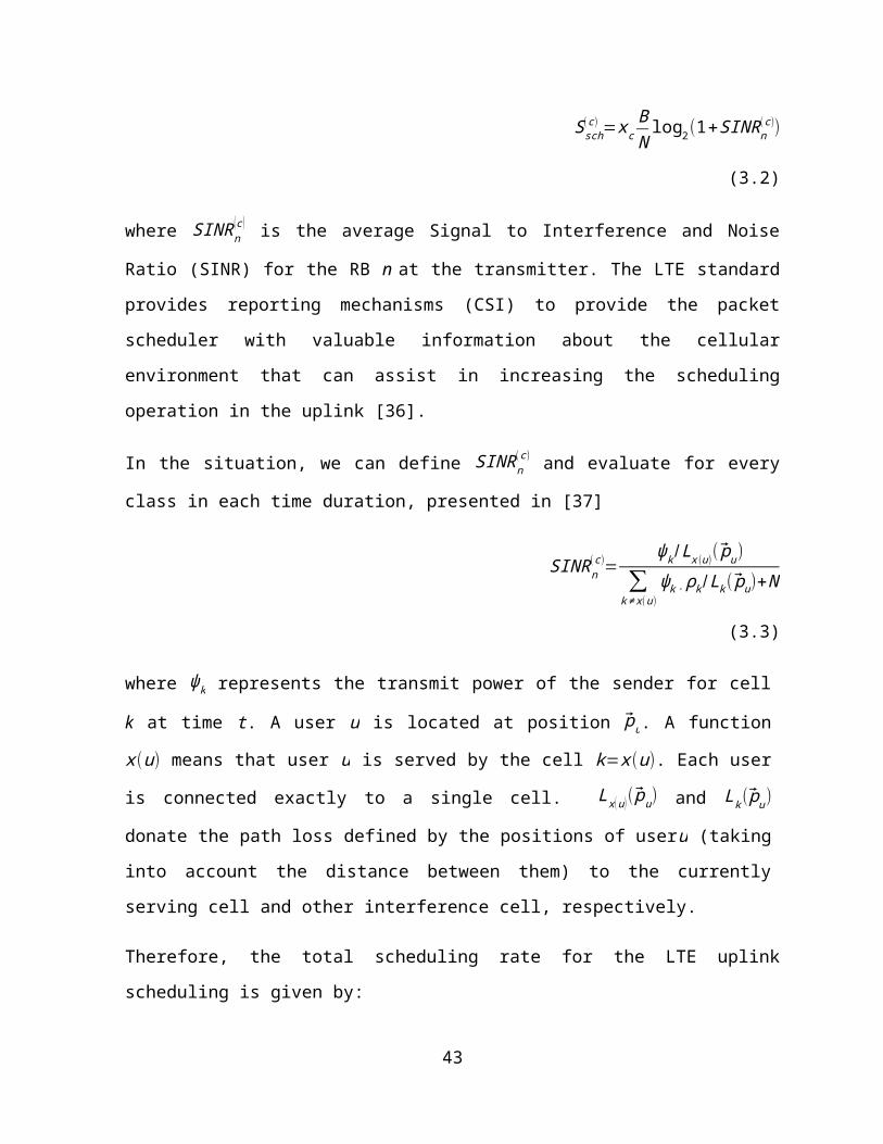
The objective function (4.7a) represents the combination of the RB utilization and the load
balancing level with the weight parameter,0<δ<1. Constraint (4.7b) shows that the number
of resource blocks occupied by all users in a cell should not exceed the total number of
resource blocks in the cell. Constraint (4.7c) specifies that each UE can be served by only one
eNB. Constraint (4.7d) represents that a user’s SINRi ,k (t ) should not be lower than the SINR
threshold SINRth in order to ensure acceptable data communications.
4.4 Practical Load-Balancing Algorithm
The optimization problem in Equation (4.7) is an integer programming, which is NP hard. If
we use exhaust search to find the optimal solution, it is not suitable for delay-sensitive smart
grid applications because the processing time will be unacceptable. In this section, we
propose a practical load-balancing algorithm which provides a sub-optimal but much more
efficient solution to problem in Equation (4.7). The principle of the proposed algorithm is
that the UE always tries to choose an eNB with the highest z value as its serving eNB.
The proposed Practical Load Balancing Algorithm is executed at each SeNB. The SeNB first
finds the set of the UEs, denoted by SUE, that are served by it, and then sorts the UEs in the
set SUE in an ascending order based on their SINR values. For each UE in the set SUE, SeNB will
find a better TeNB if available, and hand over the UE to the chosen TeNB. The process of
finding the better TeNB is as follows. First, the SeNB finds the set of the target TeNBs,
denoted by W, for the current UE. Then, for each TeNB in the set W, the SeNB calculates the
number of required resource blocks if the UE is handed over to the TeNB, and compares the
current value zSeNB with the z value of the TeNB zTeNB. If the difference between zSeNB and
zTeNBis larger than a thresholdρth, the UE will be handed over from the current SeNB to the
TeNB. The same procedure repeats until all UEs in the set SUE have been processed by the
SeNB.
The Practical Load Balancing Algorithm is a sub-optimal solution to the optimization problem
(4.7). The advantage of the proposed algorithm is to find the near-minimum objective at a
47

much faster speed than the exhaust search approach. The difficulty of finding the solution to
the problem (4.7) lies in the processing order of the UEs at each SeNB. UE assignments affect
each other. Different processing order of UEs will lead to different results. In the Practical
Load Balancing Algorithm, the SeNB sorts the UEs in the set SUE in an ascending order based
on their SINR value, and process the UE with the lowest SINR value first. This method tries
to transfer the UE with the worst channel condition to the TeNB with a better channel
condition, which can improve the overall performance. At the same time, those UEs with
better SINR keep in relatively good channel condition, because the proposed algorithm takes
the fairness level into consideration.
Algorithm 2: the proposed practical load balancing algorithm executed at a SeNB 1: Find the set of UEs, denoted by SUE, that are currently served by the
SeNB. 2: Sort the UEs in the set SUE in an ascending order based on their
SINR values. 3: for each UE in the set SUE do 4: Calculate zSeNB value; 5: Find the set of TeNBs, denoted by W ; 6: Collect measurements (e.g., CSI) from the UE to each TeNB in
the set W ; 7: Obtain the number of the available resource blocks at each TeNB
in the set W ; 8: for each TeNB in the set W do 9: if SINR≥ SINRth then 10: Calculate the number of required resource blocks after the
handover; 11: Calculate the zTeNB value; 12: if zSeNB−zTeNB>ρth then 13: Perform handover from SeNB to TeNB; 14: break; 15: end if 16: end if 17: end for 18: end for
48

If a handover is performed as long as the UEs’ z value of TeNB zTeNB is smaller than that of
SeNB zSeNB, it may lead to handover ping-pong effect, which means that a UE switches its
SeNB frequently and cannot reach a stable state. In order to prevent the handover ping-pong
effect, we introduce an offset value ρth in our algorithm. Only when ZSeNB−ZTeNB> ρth, the UE
triggers a handover. Therefore, it is critical to define ρth. A smaller ρth may still cause the
ping-pong effect, while a larger ρth would make the Practical Load Balancing Algorithm
perform worse.
4.5 Simulations
OPNET Modeler [41] is a network simulation tool. It provides a comprehensive development
environment for modeling and simulation of deployed wired and wireless networks. OPNET
Modeler enables users to create customized models and to simulate various network
scenarios. The wireless module is used to create models for wireless scenarios such as Wi-Fi
and LTE. The Modeler is object-oriented and employs a hierarchical approach to model
communication networks. It provides graphical user interfaces known as editors to capture
the specifications of deployed networks, equipment, and protocols.
OPNET Modeler 17.1 is used to simulate the smart grid LTE WAN. OPNET provides high-
fidelity modeling, simulation, and analysis of wireless networks such as interference,
transmitter/receiver characteristics, and full protocol stack, including MAC, routing, higher
layer protocols and applications. It also has the ability to incorporate node mobility and
interconnect wire line transport networks.
4.5.1 Simulation Settings
OPNET models developed for smart grid WAN architecture in a city-scale network of 5km ×
5km are shown in Figure 4.1. The scenario consists of 2 eNBs (eNodeB 1 and eNodeB 2), 8
UEs (node 1 – node 8) and a server. The eNBs are evenly located in the city area. Every 4 UEs
49

are connected to an eNB. Node1_1 to Node 1_4 are initially connected to eNodeB_1, and
Node_2_1 to Node2_4 are connected to eNodeB_2. The IP addresses assigned to Node_1_1
and Node_2_4 are 192.168.7.2 and 192.168.7.9, respectively, and the IP address of the
server is 192.168.4.2. The server connects to the EPC by a link. Each UE have the same
configuration in terms of the applications and the traffic volumes. The SINR threshold SINRth
is set to 10 dB, and the system bandwidth is set to 5 MHz. We set the weight parameter δ to
0.7, which means that we pay more attention to the utilization of network resources. The
topology shown in Figure 4.1 is used in load balancing evaluation and end-to-end delay
evaluation.
Table 4.1 shows the traffic parameters for the OPNET simulation. Each UE sends the traffic
every one second. In each time period (1 second), the UE sends 500 packets, which follow a
Poisson distribution, and the packet size is 1024 bytes. Table 4.2 shows the basic LTE
parameters in OPNET simulation. We assume that eNodeB_1 is the overloaded cell, and each
UE of eNodeB_2 sends additional traffic according to a Poisson process with sending rate
increased from 1000 kbps to 6000 kbps.
Figure 4.1 Network topology in the simulation
50
Table 4.7 Parameter settings of traffic
Traffic sent Value
Packet size (bytes) Constant (1024)
Number of packets sent once Poisson (500)
Initialization time (seconds) Poisson (200)
Inter-request time (seconds) Poisson (1)
Table 4.8 Major Simulation Parameters of LTE
Parameter Setting
Uplink base frequency 1920 MHz
Downlink base frequency 2110 MHz
Uplink bandwidth 20 MHz
Downlink bandwidth 20 MHz
4.5.2 Simulation Results
4.5.2.1 Comparison between the proposed Practical Load Balancing Algorithm and
the exhaust search approach
The Figure 4.2 shows the comparison of z value among the proposed Practical Load
Balancing Algorithm, the exhaust search approach, and the default handover approach. The
red, green, blue lines represent the proposed algorithm, the exhaust search, and the default
handover, respectively. The LTE default handover approach is that the UE switches to other
eNB with the best channel condition as long as the SINR of the UE is larger than the SINR
threshold. The exhaust search approach finds the optimal solution to the optimization
problem (4.7) at the price of extremely high computational complexity. The proposed
Practical Load Balancing Algorithm is an efficient and lightweight algorithm, which performs
close to the globally optimal result, as demonstrated from the small performance gap
between the proposed algorithm and the exhaust search approach in Figure 4.2. We can see
that the exhaust search approach and the proposed algorithm get much lower z values than
51

the default handover approach. Thus the proposed algorithm and exhaust search approach
consume less resource and provide more balanced load for LTE system than the default
handover approach.
Figure 4.12 Comparison of z values among the proposed algorithm, the exhaust search approach, and
the default handover approach
4.5.2.2 Load Balancing Evaluation
Figure 4.3 shows the comparison of average RB utilization ratio between the default
handover approach and our proposed algorithm. The blue line represents the proposed
scheme, while the red one represents the LTE default handover scheme. With the increased
sending rate, both curves keep rising up, but the line of proposed algorithm is increasing
slowly than the default handover scheme. The additional traffic injection from Node_1_1 to
Node_1_4 makes the SINR of cell 1 worse. A worse cell would use more RBs to send the
same amount of data. Through the handover, the channel conditions of the UEs become
better than before. The switched UEs with better SINR consume less resource, thus leading
to a lower average RB utilization ratio compared to the default handover scheme.
52

Figure 4.13 Comparison of average RB utilization ratio between the proposed algorithm and the
default handover scheme
Figure 4.14 Comparison of load balancing ratio between the proposed algorithm and the default
handover scheme
53

Figure 4.4 shows the comparison of load balancing ratio between the proposed algorithm
and the default handover scheme. It is clear from the figure that the load balancing ratio for
the default handover scheme reduces dramatically when the sending rate is increased. The
proposed algorithm achieves a higher load balancing ratio (e.g., a more balanced load
distribution) than the default handover scheme. The reason is that the proposed algorithm
can appropriately transfer a part of UEs from the over-loaded cell to the under-loaded cell to
balance the load.
4.5.2.3 End-to-end Delay Evaluation
Figure 4.5 illustrates the end-to-end delay between UEs and eNBs. The corresponding IP
addresses of UEs and the server are shown in Table 4.3. As shown in the figure, all traffic
starts after around 100 seconds. After several seconds, the values of end-to-end delays
become steady. In eNodeB_1, the values remain at around 0.025 s, while in eNodeB_2, the
delay values vary between 0.024 s and 0.028 s. That is due to different distances between
the UEs and eNodeB, which leads to different channel conditions.
Table 4.9 IP address corresponding
Node IP Address
Node_1_1 192.0.7.2
Node_1_2 192.0.7.3
Node_1_3 192.0.7.4
Node_1_4 192.0.7.5
Node_2_1 192.0.7.6
Node_2_2 192.0.7.7
Node_2_3 192.0.7.8
Node_2_4 192.0.7.9
Server 192.0.4.2
54

In order to evaluate the load distribution among cells, additional traffic is added to
Node_2_1, Node_2_2, Node_2_3, and Node_2_4. The additional traffic is injected at the 3rd
minute from the beginning, and we observe the change of end-to-end delay before and after
the traffic injection. Figure 4.6 shows the end-to-end delays of the UEs after inserting the
traffic flow. As shown in the Figure 4.6(a), the UEs’ delay at eNodeB_1 does not have too
much change compared with the value before the traffic injection. Because the two cells are
separated, the traffic injection in cell 2 does not affect the cell-1 network. Figure 4.6(b)
shows the delays in default hand-over scheme, the delay values of all four nodes connected
to eNodeB_2 start to increase from the third minute, and finally go above 0.04 second. The
traffic injection makes the channel condition of Node_1_1, Node_1_2, Node_1_3 and
Node_1_4 worse. However, the SINR values do not reach the thresholds. Therefore, the UEs
do not take any hand-over action, so that the end-to-end delays are increased.
(a) End-to-end delays for Node_1_1 - Node_1_4
55
Node_1_1
Node_1_2Node_1_3 Node_1_4
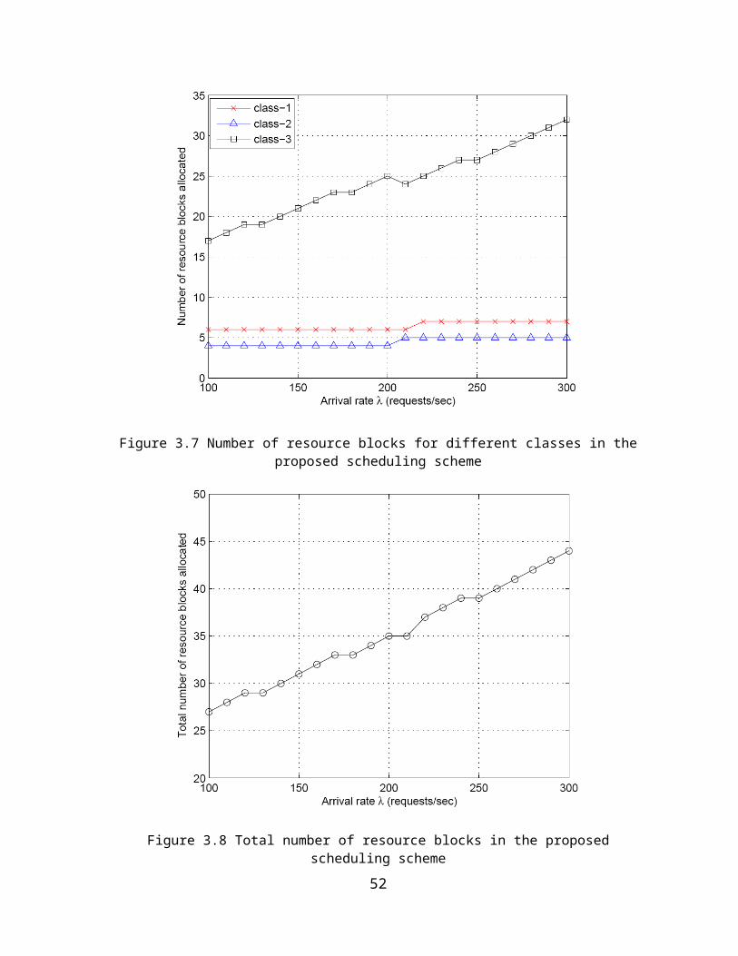
(b) End-to-end delays for Node_2_1 - Node_2_4
Figure 4.15 End-to-end delays before adding the traffic
(a) End-to-end delays for Node_1_1 - Node_1_4
56
Node_2_3
Node_2_2 Node_2_4
Node_2_1

(b) End-to-end delays for Node_2_1 - Node_2_4
Figure 4.16 End-to-end delays with the default handover scheme after adding traffic flows
We implemented the proposed algorithm into the OPNET experiments. Figure 4.7 shows the
delay values after implementing the proposed practical load balancing algorithm. When the
additional traffic flow is added to eNodeB_2, the delay values of Node_2_1 to Node_2_4
start soaring, as shown in Figure 4.7(b). The increased delays are caused by the overload in
eNodeB_2 when a large amount of traffic is inserted into it. When the time reaches 4 minute
20 seconds, the delay values stop increasing and start going down, as shown in Figure 4.7(b).
This phenomenon occurred due to the fact that the proposed algorithm was triggered to
hand over the UEs with worse channel conditions to the new SeNB, thus leading to delay
reduction. In this case, Node_2_3 switches its SeNB from eNodeB_2 to eNodeB_1. After the
handover, the end-to-end delays become acceptable. Node_1_1 to Node_1_4 have
fluctuations at this time which are caused by the handover. With more traffic injected, the
end-to-end delays soar again. At the time of 5 minute 20 seconds, the SeNB of Node_2_1 is
also switched to eNodeB_1, which leads to another delay reduction in Figure 4.7(b).
57

(a) End-to-end delays for Node_1_1 - Node_1_4
(b) End-to-end delays for Node_2_1 - Node_2_4
Figure 4.17 End-to-end delays with the proposed algorithm after adding traffic flows
Figure 4.8 shows the SeNB for each node during the experiment period. Originally,
Node_1_1 to Node_1_4 are connected to eNodeB_1, and Node_2_1 to Node_2_4 are
connected to eNodeB_2. Due to the additional traffic injection to eNodeB_2, Node_2_3 was
handed over from eNodeB_2 to eNodeB_1 at time of 260 seconds, and Node_2_1 was
handed over from eNodeB_2 to eNodeB_1 at time of 320 seconds. The handover is triggered
by the proposed algorithm.
58

1
2Node_1_1
Time (sec)
eNod
eB
Num
ber
1
2
Node_1_2
Time (sec)
eNod
eBN
umbe
r
1
2
Node_1_3
Time (sec)
eNod
eBN
umbe
r
1
2
Node_1_4
Time (sec)
eNod
eBN
umbe
r
1
2
Node_2_1
Time (sec)
eNod
eBN
umbe
r
1
2
Node_2_2
Time (sec)
eNod
eBN
umbe
r
12
Node_2_3
Time (sec)
eNod
eBN
umbe
r
12
Node_2_4
Time (sec)
eNod
eBN
umbe
r
59

Figure 4.18 The SeNB for each node with the proposed algorithm during the experiment period
4.6 Chapter Summary
In this chapter, we investigated the LTE load balancing problem. We proposed a practical
Load Balancing Algorithm for LTE to reduce the average end-to-end delay and increase the
load balancing ratio. We conducted experiments in OPNET. The experiments results
demonstrated that the proposed Load Balancing Algorithm led a lower delay and better load
balance than the default handover scheme.
60
Chapter 5
Conclusion and Future Research
Directions
5.1 Conclusions
In the next-generation smart grid WAN networks, the wireless communication technology
will play the essential role due to its advancement and flexibility. The LTE is the promising
option for smart grid because of its higher data rates, lower latency and larger coverage.
In this thesis, we proposed an optimal LTE uplink scheduling algorithm and a LTE load
balancing algorithm for smart grid Wide Area Network. Latency is a critical element in smart
grid networks. Many real-time smart grid applications have a low latency requirement. The
presented algorithms specifically aim to reduce the transmission latency from the UEs to the
LTE eNB.
Smart grid communication network consists of different classes of traffic in terms of
importance, which have different QoS requirements. In LTE QoS mechanism, the scheduler
acts as a key role, which defines which kind of traffic is served first and how different class of
61

traffic should be transmitted. For this purpose, we propose a new optimal LTE uplink
scheduling algorithm for smart grid WAN. Different from the existing scheduling algorithms,
we apply a queuing model to calculate the scheduling time of the scheduling process. Based
on different scheduling time requirements for different classes of traffic, the resource blocks
are allocated to different users in a differentiated way. The proposed scheduling algorithm
can utilize the minimal resource to satisfy the scheduling time requirements for different
classes of traffic. The simulation results demonstrated that the proposed scheduling
algorithm outperforms the existing scheduling algorithms in terms of resource utilization.
In LTE networks with multiple cells, load imbalance may cause congestions. Therefore, it is
crucial to appropriately distribute the load among cells. We formulate the load balancing
problem in multi-cell LTE networks, considering both the resource utilization ratio and the
load balancing level. We proposed a practical Load Balancing Algorithm to solve the load
balancing problem. The experimental results in OPNET demonstrated that the proposed load
balancing algorithm can obtain a lower average end-to-end delay and a better load balance
than the default handover scheme.
5.2 Future Research Directions
The thesis is based on 3GPP LTE standards Release 8, which has been deployed in industry in
many countries. While the newer release-LTE Release 9 or even LTE-Advanced standards are
currently under development. The newer standards provide higher performance than
Release 8 (for example, data rate). LTE-advanced also adds new features such as relay-based
networking, which greatly enlarge the coverage of the signal and optimize the load balancing
mechanism. In the near future, the research attention will be focuses on the newer LTE
standard for smart grid communications.
Moreover, the models proposed in this thesis can be further developed and enhanced to
give a more comprehensive and accurate representation for the LTE network.
62

Bibliography
[1] L. B. Le and T. Le-Ngoc, “QoS provisioning for OFDMA-based wireless network
infrastructure in smart grid,” in proc. of IEEE Electrical and Computer Engineering 2011
24th Canadian Conference on CCECE, pp. 813-816, May 2011.
[2] Y. Kim and M. Thottan, “SGTP: smart grid transport protocol for secure delivery
periodic real time data,” Bell Labs Technical Journal, vol. 16, no. 3, pp. 83-99, Dec 2011.
[3] O. C. Onar, M. Starke, G. P. Andrews and R. Jackson, “Modeling, controls, and
applications of community energy storage systems with used EV/PHEV batteries,” in
proc. of IEEE Transportation Electrification Conference and Expo (ITEC), June 2012.
[4] B. P. Roberts and C. Sandberg, “The role of energy storage in development of smart
grids,” Proceedings of the IEEE, vol. 99, no. 6, pp. 1139-1144, June 2011.
[5] P. Cheng, L. Wang, B. Zhen and S. Wang, “Feasibility study of applying LTE to smart
grid”, in proc. of Smart Grid Modeling and Simulation (SGMS), 2011 IEEE First
International Workshop, pp. 108-113, Oct 2011.
[6] B.A. Bjerke and QUALCOMM INC, “LTE-advanced and the evolution of LTE
deployments”, IEEE Wireless Communications, vol. 18,no. 5, pp. 4-5, Oct 2013.
[7] Smart Grid = Information and Communication Technologies. [Online]. Available:
http://www.ic.gc.ca/eic/site/028.nsf/eng/00382.html
63

[8] A. Ghosh and R. Ratasuk, Essentials of LTE and LTE-A, Cambridge University Press, July
2011.
[9] H. Holma and A. Toskala, LTE for UMTS - OFDMA and SC-FDMA based radio access,
John Wiley and Sons, 2009.
[10] 3GPP TS 36.101: “Evolved Universal Terrestrial Radio Access (E-UTRA); User Equipment
(UE) radio transmission and reception”, 3GPP, ver. 8.7.0, rel. 8, 2009.
[11] J. Ekanayake, N. Jenkins, K. Liyanage, J. Wu and A. Yokoyama, Smart grid: technology
and applications, John Wiley & Sons, 2009.
[12] V.C. Gungor, B. Lu, and G.P. Hancke, "Opportunities and challenges of wireless sensor
networks in smart grid." IEEE Transactions on Industrial Electronics, vol. 57, no. 10, pp.
3557-3564, Feb 2010.
[13] A. Aggarwal, S. Kunta, and P.K. Verma. “A proposed communications infrastructure for
the smart grid,” in proc. of IEEE Innovative Smart Grid Technologies (ISGT), Jan 2010.
[14] O. Delgado and B. Jaumard, “Scheduling and resource allocation in LTE uplink with a
delay requirement,” in proc. of 2010 IEEE Eighth Annual Communication Networks and
Services Research Conference (CNSR), pp. 268-275, May 2010.
[15] F.D. Calabrese, C. Rosa, K.I. Pedersen and P.E. Mogensen, “Performance of
proportional fair frequency and time domain scheduling in LTE uplink,” In proc. of 2009
IEEE European Wireless Conference, pp. 271-275, May 2009.
[16] Y. Xu, and C. Fischione, “Real-time scheduling in LTE for smart grids,” in proc. of 2012
5th IEEE International Symposium on Communications Control and Signal Processing
(ISCCSP), May 2012.
[17] E. Yaacoub and Z. Dawy, “A game theoretical formulation for proportional fairness in
LTE uplink scheduling,” in proc. of 2009 IEEE Wireless Communications and Networking
Conference, Apr 2009.
[18] S.N.K. Marwat, T. Weerawardane, Y. Zaki, C. Goerg and A. Timm-Giel, “Performance
evaluation of bandwidth and QoS aware LTE uplink scheduler,” Wired/Wireless
Internet Communication, pp. 298-306, 2012.
64

[19] M. Anas, C. Rosa, F. Calabrese, K. Pedersen and P. Mogensen, “Combined admission
control and scheduling for QoS differentiation in LTE uplink,” in proc. of 2008 IEEE 68th
Vehicular Technology Conference, Sept 2008.
[20] S. Ali, M. Zeeshan and A. Naveed, "A capacity and minimum guarantee-based service
class-oriented scheduler for LTE networks," EURASIP Journal on Wireless
Communications and Networking, Mar 2013.
[21] Z. Li, C. Yin and G. Yue, “Delay-bound power-efficient packet scheduling for uplink
systems of LTE,” in proc. of 2009 5th International Conference on Wireless
Communications, Networking and Mobile Computing, pp. 339-345, Sept 2009.
[22] F. Sokmen and T. Girici, “Uplink resource allocation Algorithms for Single Carrier FDMA
systems," in proc. of 2010 IEEE European Wireless Conference, pp. 339-345, Apr 2010.
[23] I. Viering, M. Dottling and A. Lobinger, “A mathematical perspective of self-optimizing
wireless networks,” in proc. of 2009 IEEE International Conference on Communications,
June 2009.
[24] A. Lobinger, S. Stefanski, T. Jansen, and I. Balan, “Load balancing in downlink LTE self-
optimizing networks,” in proc. of 2010 IEEE 71st Vehicular Technology Conference (VTC
2010-Spring), May 2010.
[25] K.A. AliHossam H.S. Hassanein and H.T. Mouftah, “Directional cell breathing based
reactive congestion control in WCDMA cellular networks,” in proc. of 2007 IEEE 12th
Symposium on Computers and Communications (ISCC), pp. 685-690, July 2007.
[26] Y. Yang, P. Li, X. Chen and W. Wang, “A high-efficient algorithm of mobile load
balancing in LTE system,” in proc. of 2012 IEEE Vehicular Technology Conference, Sept
2012.
[27] 3GPP TS 36.321, “Evolved Universal Terrestrial Radio Access (E-UTRA); Medium Access
Control (MAC) Protocol Specification,” 3GPP, ver. 8.12.0, rel. 8, Mar 2012.
[28] Yan, Ye, Yi Qian, Hamid Sharif and David Tipper, “A survey on smart grid
communication infrastructures: Motivations, requirements and challenges,” IEEE
Communications Surveys & Tutorials, vol. 15, no. 1, pp. 5-20, Feb 2012.
65

[29] A. Aggarwal, S. Kunta, and P.K. Verma. “A proposed communications infrastructure for
the smart grid,” in proc. of IEEE Innovative Smart Grid Technologies (ISGT), Jan 2010.
[30] V.C. Gungor, D. Sahin, T. Kocak, S. Ergut, C. Buccella, C. Cecati and G.P. Hancke. “Smart
grid technologies: communication technologies and standards,” IEEE transactions on
Industrial informatics, vol. 7, no. 4, pp. 529-539, Nov 2011.
[31] Electric Power Research Institute (EPRI), “Report to NIST on the Smart Grid
interoperability standards roadmap,” Aug 2009.
[32] Z. Feng, J. Liu and Y. Zhang, “Study on the application of advanced broadband wireless
mobile communication technology in smart grid,” in proc. of 2010 IEEE International
Conference on Power System Technology (POWERCON), Oct 2010.
[33] D. Gross and C. M. Harris, Fundamentals of queuing theory, Wiley, 1998.
[34] M. M. Tantawy, A. S. T. Eldien and R. M. Zaki, “A novel cross-layer scheduling algorithm
for Long Term-Evolution (LTE) wireless system,” Canadian Journal on Multimedia and
Wireless Networks, vol. 2, no. 4, pp. 57-62, Dec 2011.
[35] 3GPP TR 36.942: “ETSI TR 136 942; LTE; evolved universal terrestrial radio access(E-
UTRA); radio frequency (RF) system scenarios,” 3GPP, ver. 9.3.0 Rel. 9), 2012
[36] H. Safa and K. Tohme, “LTE uplink scheduling algorithms: performance and
challenges,” in proc. of 2012 IEEE 19th International Conference on
Telecommunications, Apr 2012.
[37] J. G. Andrews, R. K. Ganti, M. Haenggi, N. Jindal and S. Weber, “A primer on spatial
modeling and analysis in wireless networks,” IEEE Communications Magazine, vol. 48,
no. 11, pp. 156--163, 2010.
[38] M. Alasti, B. Neekzad, J. Hui, R. Vannithamby, “Quality of Service in WiMAX and LTE
networks [topics in wireless communications],” in proc. of 2010 IEEE International
Conference on Communication Systems (ICCS), vol. 48, no. 5, pp. 104-111, May 2010.
[39] Z. Li, H. Wang, Z. Pan, N. Liu and X. You, “Joint optimization on load balancing and
network load in 3GPP LTE multi-cell networks,” in proc. of 2011 IEEE International
Conference on Wireless Communications and Signal Processing (WCSP), Nov 2011.
66
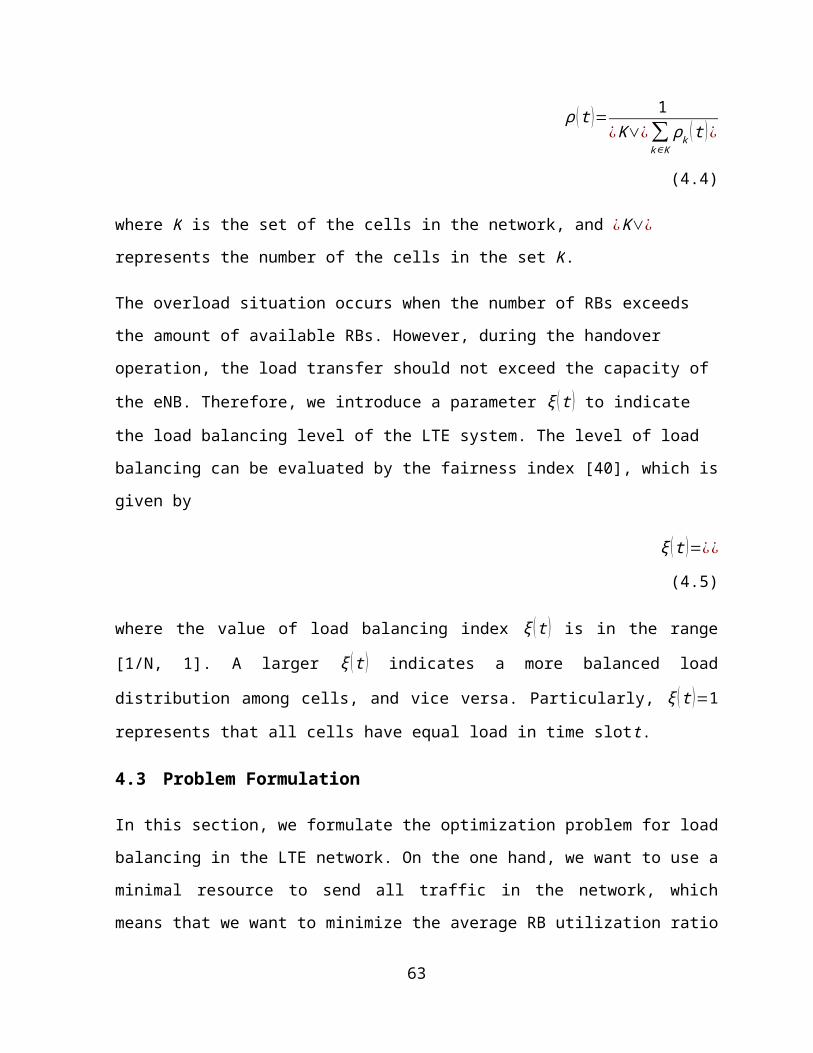
[40] D. Chiu and R. Jain, “Analysis of the increase and decrease algorithms for congestion
avoidance in computer networks,” Computer Networks and ISDN Systems, vol. 17, no.
1, pp. 1-14, Jun 1989.
[41] OPNET Modeler network simulation software [Online]. Available: www.opnet.com.
67