smart design and best practice of vehicle manufacturing
TRANSCRIPT

Smart Designs and Best Practices
of Vehicle Manufacturing
Tallrain Zhang, Jul 2015

Data
• 4 Processes: Stamping, Welding, Painting, Assembly.
• A car body is made of 300-500 pieces of steel plates.
• A car contains 5000-6000 welding points, 90% of them are welded by Robots.
• A car will be covered by 4-6 layers of paint, 90% of operations are done by Robots.
• A car goes through 200+ assembly stations before it’s completed.

Systems• Scheduling System: which car to build, how to build it, how to
communicate with Plan Layer and Device Layer.
• Kanban & Andon.
• Error Proofing: of material rack, of tools.
• Quality System: Defect, Short Build, Scrap, Quality Gate.
• Key material genealogy.
• Kitting System.
• Call Material System.
• Measuring System.
Cooperation
• ERP to deliver Work Order information.
• PLM to deliver BOM data.
• WMS to deliver material and warehouse information.
• MES to schedule work orders, to define BOM into station level, and then to define Error Proofing. MES to talk with PLC via OPC.
• PLC defines logic level of all devices which need to talk to upper level systems.
• Device/Robots/Tools/Sensors to execute physical control operations.
Scheduling – Get New Order
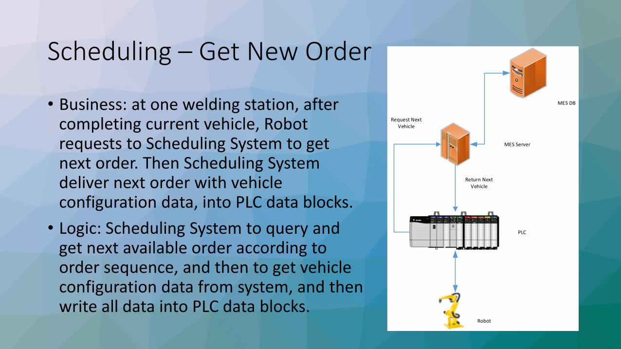
• Business: at one welding station, after completing current vehicle, Robot requests to Scheduling System to get next order. Then Scheduling System deliver next order with vehicle configuration data, into PLC data blocks.
• Logic: Scheduling System to query and get next available order according to order sequence, and then to get vehicle configuration data from system, and then write all data into PLC data blocks.
Robot
PLC
MES Server
MES DB
Return Next Vehicle
Request Next Vehicle
Scheduling – Read Order
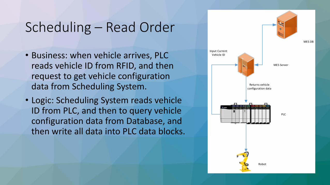
• Business: when vehicle arrives, PLC reads vehicle ID from RFID, and then request to get vehicle configuration data from Scheduling System.
• Logic: Scheduling System reads vehicle ID from PLC, and then to query vehicle configuration data from Database, and then write all data into PLC data blocks.
Robot
PLC
MES Server
MES DB
Returns vehicle configuration data
Input Current Vehicle ID
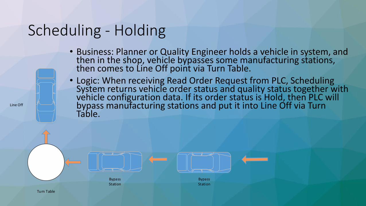
Scheduling - Holding• Business: Planner or Quality Engineer holds a vehicle in system, and
then in the shop, vehicle bypasses some manufacturing stations, then comes to Line Off point via Turn Table.
• Logic: When receiving Read Order Request from PLC, Scheduling System returns vehicle order status and quality status together with vehicle configuration data. If its order status is Hold, then PLC will bypass manufacturing stations and put it into Line Off via Turn Table.
Turn Table
BypassStation
Line Off
BypassStation

Scheduling – Turn Table
• Business: when vehicle comes through Turn Table, PLC checks its order status and quality status, and then route it into next manufacturing station, or Repair Zone, or Line Off.
• Logic: Scheduling System checks order status and quality status with vehicle ID, and then write data into PLC. PLC routes vehicle according to the data value of PLC data blocks.
Turn Table
Line Off
Repair Zone
Manufacturing Station
Manufacturing Station
Manufacturing Station
Manufacturing Station

Scheduling – Secured Gates
• Business: when vehicle comes through a Secured Gate, Traffic Light shows route direction, and release gate if it’s allowed.
• Logic: Scheduling System writes order status and quality status into PLC, then based on the combination of these 2 values, PLC decides to route vehicle into different directions, and controls Traffic Light and Gate Releasing accordingly.
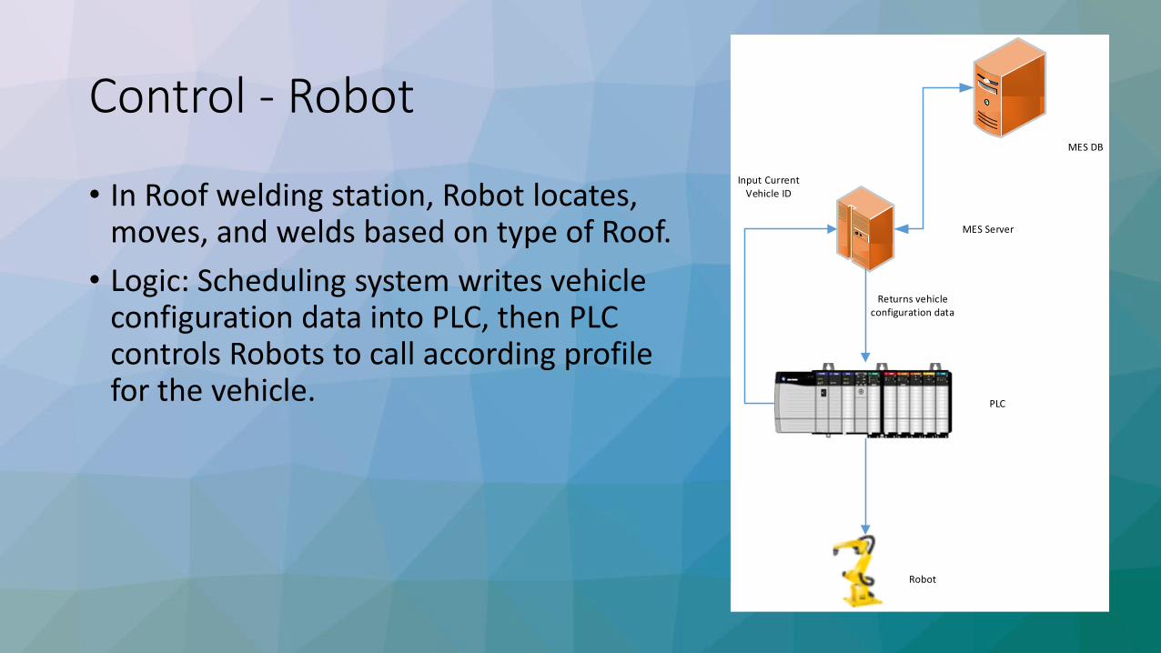
Control - Robot
• In Roof welding station, Robot locates, moves, and welds based on type of Roof.
• Logic: Scheduling system writes vehicle configuration data into PLC, then PLC controls Robots to call according profile for the vehicle.
Robot
PLC
MES Server
MES DB
Returns vehicle configuration data
Input Current Vehicle ID

Control – Device with PLC
• Business: at Engine assembly shop, Filling Machine fills according volume of gas for each coming Engine.
• Logic: PLC sends out Engine ID, then Scheduling System queries product BOM and gets item number of Gas Tank, and then converts it into mapping value according to MES/PLC protocol. Then PLC controls machine to fill gas accordingly.
Filling Machine
PLC
MES Server
MES DB
Returns vehicle configuration data
Input Current Vehicle ID

Control – Device with PC
• Business: In Nameplate Laser Scribing station, Laser Machine scribes vehicle ID and its configuration data for each vehicle.
• Logic: Scheduling System shares remote view to PC, which controls Laser Machine. So this PC can get all data for each coming vehicle.
MES DB
Control PC
Laser Machine
Remote View

Control – Typical Handshaking
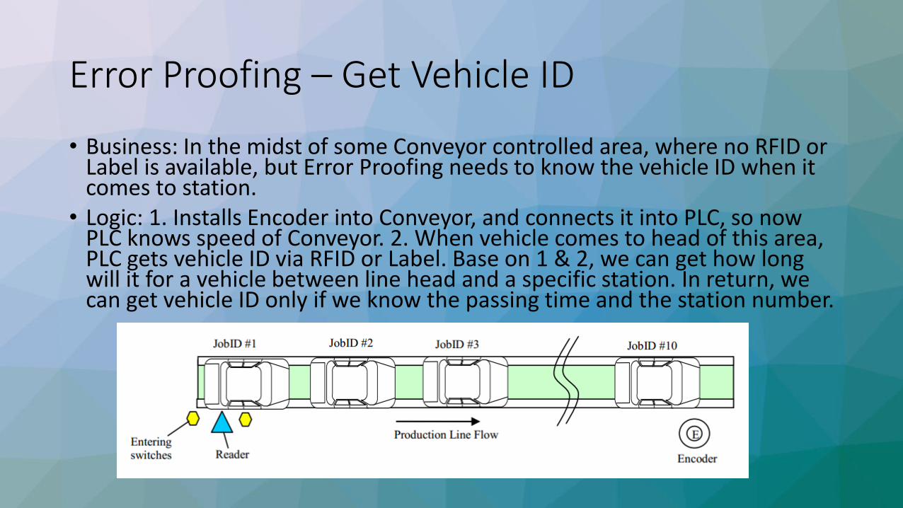
Error Proofing – Get Vehicle ID
• Business: In the midst of some Conveyor controlled area, where no RFID or Label is available, but Error Proofing needs to know the vehicle ID when it comes to station.
• Logic: 1. Installs Encoder into Conveyor, and connects it into PLC, so now PLC knows speed of Conveyor. 2. When vehicle comes to head of this area, PLC gets vehicle ID via RFID or Label. Base on 1 & 2, we can get how long will it for a vehicle between line head and a specific station. In return, we can get vehicle ID only if we know the passing time and the station number.
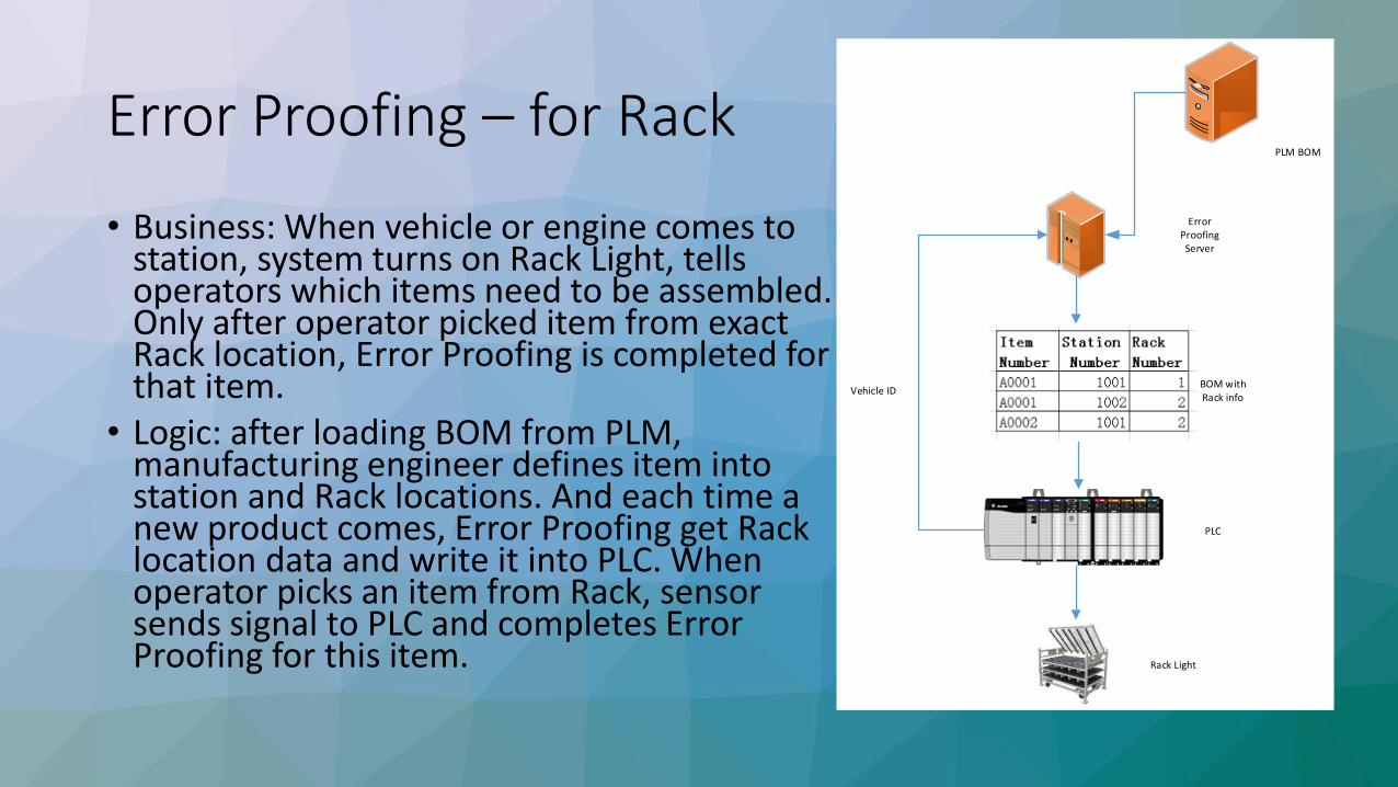
Error Proofing – for Rack
• Business: When vehicle or engine comes to station, system turns on Rack Light, tells operators which items need to be assembled. Only after operator picked item from exact Rack location, Error Proofing is completed for that item.
• Logic: after loading BOM from PLM, manufacturing engineer defines item into station and Rack locations. And each time a new product comes, Error Proofing get Rack location data and write it into PLC. When operator picks an item from Rack, sensor sends signal to PLC and completes Error Proofing for this item.
Error Proofing Server
PLM BOM
BOM with Rack info
PLC
Rack Light
Vehicle ID
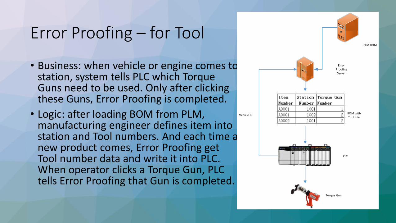
Error Proofing – for Tool
• Business: when vehicle or engine comes to station, system tells PLC which Torque Guns need to be used. Only after clicking these Guns, Error Proofing is completed.
• Logic: after loading BOM from PLM, manufacturing engineer defines item into station and Tool numbers. And each time a new product comes, Error Proofing get Tool number data and write it into PLC.When operator clicks a Torque Gun, PLC tells Error Proofing that Gun is completed.
Error Proofing Server
PLM BOM
BOM with Tool info
PLC
Torque Gun
Vehicle ID

Quality - Defect
• Business: at assembly or quality check stations, operator could input Quality Defects. And in Turn Tables or Quality Gate, products with Defects will be identified and sent to Repair Zone.
• Logic: After defect input, system updates vehicle’s quality status. And in Turn Table or Quality Gate, PLC gets quality status from system and controls routes accordingly.
Have Defect?Quality Status
Turn Table
Quality Gate
Repair Zone

Quality – Short Build
• Business: at quality control points, system detects if any parts are short built, and then alert operators for it.
• Logic: manufacturing engineer defines BOM into station level as To-build BOM, and system records all parts already assembled as Built BOM. To-build BOM – Built BOM = Short Build BOM.
MES Server
PLM BOM
To Build BOM
Finding Short Build?
Built BOM
Quality Status
Quality Gate
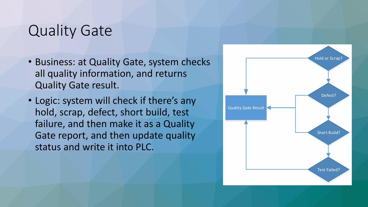
• Business: at Quality Gate, system checks all quality information, and returns Quality Gate result.
• Logic: system will check if there’s any hold, scrap, defect, short build, test failure, and then make it as a Quality Gate report, and then update quality status and write it into PLC.
Hold or Scrap?
Defect?
Short Build?
Test Failed?
Quality Gate Result

Testing – Device with PLC
• Business: when vehicle comes into test device, system sends test profiles, parameters into device, and collect data and result from it.
• Logic: based on vehicle ID, system queries database and gets test parameters for the station and writes into PLC. PLC controls device to test and then sends data and result back into system.
Test Device
PLC
MES Server
MES DB
Return Test Parameters
Input Vehicle ID
Test Parameters Test Result
Upload Test Result
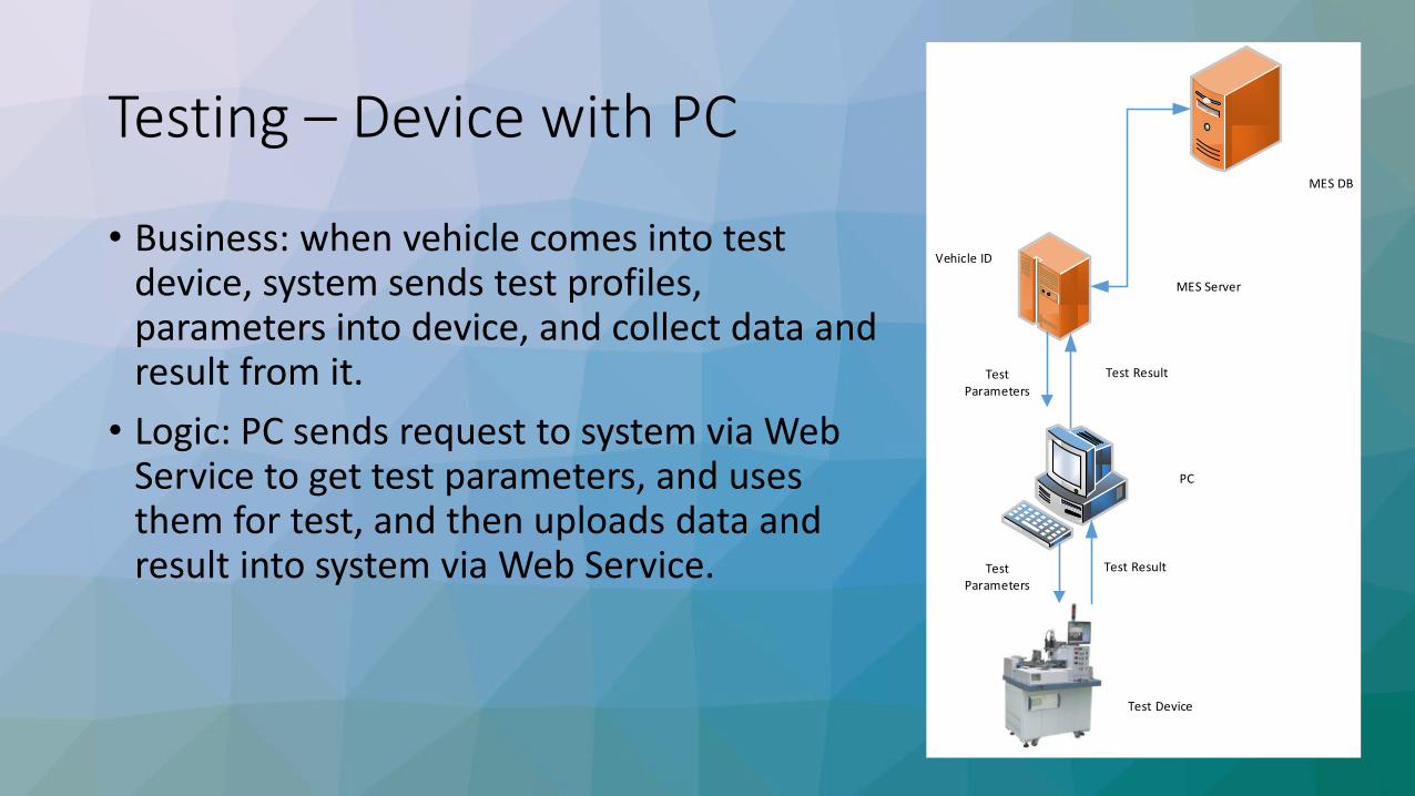
Testing – Device with PC
• Business: when vehicle comes into test device, system sends test profiles, parameters into device, and collect data and result from it.
• Logic: PC sends request to system via Web Service to get test parameters, and uses them for test, and then uploads data and result into system via Web Service.
Test Device
PC
MES Server
MES DB
Test Result
Vehicle ID
Test Parameters
Test Parameters
Test Result

Material – Kitting by Sequence
• Business: Kitting according to vehicle sequence, delivery according to sequence.
• Logic: when vehicle passes trigger point, Scheduling System calls Kitting station for that vehicle with Kitting BOM configured for the Kitting station, and when Kitting is completed, Kitting box will be delivered into assembly station by sequence.
Trigger Point
Call MaterialDeliver
Material
Kitting Station
AssemblyStation
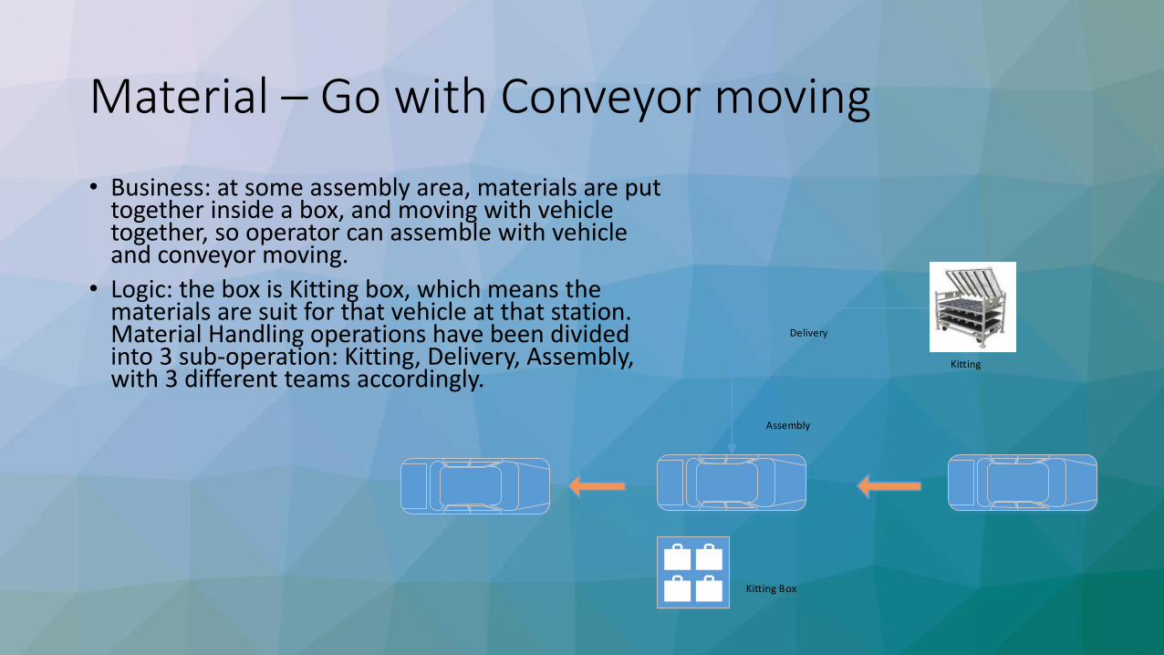
Material – Go with Conveyor moving
• Business: at some assembly area, materials are put together inside a box, and moving with vehicle together, so operator can assemble with vehicle and conveyor moving.
• Logic: the box is Kitting box, which means the materials are suit for that vehicle at that station. Material Handling operations have been divided into 3 sub-operation: Kitting, Delivery, Assembly, with 3 different teams accordingly.
Delivery
Kitting
Assembly
Kitting Box

Thank you!