smart board installation guide for sb2 or sb3 smart...
TRANSCRIPT

Installation Guide

FCC WarningThis equipment has been tested and found to comply with the limits for a "Class B" digital device, pursuant to Part 15 of the FCC rules. These limits are designed to provide reasonable protection against harmful interference in a residential installation. This equipment generates, uses, and can radiate radio frequency energy and, if not installed and used in accordance with the instruction, may cause harmful interference to radio communications. However, there is no guarantee that interference will not occur in a particular installation. If this equipment does cause harmful interference to radio or television reception (this can be determined by turning the equipment off and on) the user is encouraged to try to correct the interference by one or more of the following measures:
Reorient or relocate the receiving antenna.Increase the separation between the equipment and receiver.Connect the equipment into an outlet on a circuit different from that to which the receiver is connected.Consult the dealer or an experienced radio/TV technician for help.
Any changes or modifications to this "Class B" digital device that have not been expressly approved by SMART Technologies Inc. could void the user's authority to operate the equipment.
All rights reserved.
Contents
ContentsThe SMART Board ................................................................................... 1
Supplied SMART Board Software ................................................................................ 1About this Guide ........................................................................................................... 2
Installing the SMART Board.................................................................... 3Before You Begin: Unpacking and Checking Components .......................................... 3Attaching the Pen Tray to the Whiteboard.................................................................... 4Finding and Marking a Suitable Location...................................................................... 8Attaching the Wall Bracket ........................................................................................... 9Mounting the SMART Board....................................................................................... 12Connecting the Pen Tray to the Computer and Power Source .................................. 14Setting Up a SMART Board with Projection ............................................................... 18
Installing SMART Board Software ........................................................ 22SMART Board Software ............................................................................................. 22Windows System Requirements ................................................................................ 22Macintosh System Requirements............................................................................... 22Software Installation ................................................................................................... 23
Configuring and Orienting the SMART Board ..................................... 25Configuring the SMART Board ................................................................................... 25Orienting the Projected SMART Board....................................................................... 26
Customer Support ................................................................................. 29Contacting SMART Technical Support....................................................................... 29Other SMART Contacts.............................................................................................. 29Warranty ..................................................................................................................... 29User Registration Card ............................................................................................... 30
Appendix A: Glossary of Technical Terms .......................................... 31Index ....................................................................................................... 33

Contents

SMART Board Installation Guide 1
The SMART Board™
The SMART Board is an interactive, electronic whiteboard that can beused with or without a projector. The three SMART Board models – the340, the 360 and the 380 – can be mounted either on a floor stand or ona wall. The SMART Board 340 can also be mounted on a table stand orthe partition wall of an office cubicle.
The SMART Board’s touch-sensitive screen enables you to do everythingyou can do at a computer workstation − open files, conference withothers, create new or edit existing documents, play video clips, etc. −simply by touching the Board. You can also write over applications inelectronic ink using a Pen Tray pen or your finger, and then save yourannotations to a computer file for future reference and distribution.
Supplied SMART Board SoftwareThe SMART Board comes with two programs – the SMART Board driverand SMART Notebook™ – collectively called SMART Board Software.The SMART Board driver activates your SMART Board, allowing you touse your finger as a mouse, annotate over an application with electronicink, and use Board-aware applications. SMART Notebook allows you tocreate and organize notes on either a SMART Board or at your desktop,and then save, print or e-mail those notes.
These programs are distributed with the SMART Board and are alsoavailable free-of-charge from our Web site at www.smarttech.com.
The use of these programs is described in detail in the companionmanual to this installation guide, the SMART Board User’s Guide.However, the procedure for installing the SMART Board Software isdescribed in the section of this guide entitled “Installing SMART BoardSoftware.”
2 SMART Board Installation Guide
About this GuideA SMART Board can be mounted on a floor stand or on a wall; theSMART Board 340 can also be mounted on a table stand. The specificinstructions for mounting a SMART Board on a floor stand are describedin the set of instructions provided with the floor stand.
This guide describes all the procedures for mounting a SMART Board ona wall. It also provides instructions for other important procedures thatapply to both wall-mounted and floor stand-mounted SMART Boards.These include SMART Pen Tray™ attachment, Pen Tray connection tothe computer and power source, SMART Board Software installation, andprojector set-up and alignment.
This manual is for both Windows® and Macintosh® users of the SMARTBoard. Almost all of the procedures and descriptions in this manual applyto either system. However, any information that applies solely toWindows users is accompanied by a window icon in the margin, andinformation relating only to Macintosh users is distinguished by a similarlyplaced apple icon.
NOTE: Procedures common to both Windows and Macintosh aredescribed in terms of Windows conventions.

SMART Board Installation Guide 3
Installing the SMART BoardInstalling a SMART Board involves the following series of simpleprocedures:
• Attaching the Pen Tray to the whiteboard
• Finding and marking a suitable location
• Attaching the wall-mounting bracket to the wall
• Mounting the whiteboard
• Connecting the Pen Tray to the computer and power source
• Installing the SMART Board Software
• Configuring and orienting the SMART Board
Before You Begin: Unpacking and CheckingComponentsUnpack the contents of the shipping container, checking each itemremoved against the shipping check list. If any items are missing, contactSMART Technical Support.
Each SMART Board includes the following components:
• whiteboard
• Pen Tray, including a set of four bullet-tip dry erase markers, fourstyluses, and an eraser
• pair of Pen Tray brackets to attach the Pen Tray to the SMARTBoard
• pair of brackets to mount the whiteboard on the wall (found on theback of the whiteboard)
• MOD4, MOD6, and power supply cables
• Windows or Macintosh SMART Board Software (SMARTNotebook and SMART Board driver), located in a plasticenvelope.
If you are setting up aSMART Board withprojection, “SettingUp a SMART Boardwith Projection” onpage 18 providesspecial projector andBoard mountinginstructions.

4 SMART Board Installation Guide
Recommended ToolsWhile the following tools are not shipped with the SMART Board, werecommend that you have them on hand to help you in the assembly andmounting process.• bubble level
• measuring tape
• masking tape
• a pencil
Attaching the Pen Tray to the WhiteboardHardware Required• two Pen Tray mounting brackets
• Pen Tray
• Robertson screwdriver (supplied)
• MOD4 cable (the shorter, black cable with mini RJ11 4-wireconnectors at either end)
Activity OverviewTo attach the Pen Tray to the whiteboard, you will:
1. Attach the Pen Tray brackets to the Pen Tray
2. Connect the MOD4 cable to the whiteboard
3. Attach the Pen Tray to the whiteboard
4. Connect the MOD4 cable to the Pen Tray
The series of steps involved in each of these activities is described indetail below.
Step 1: Attach the Pen Tray brackets to the Pen Tray1. Place the Pen Tray topside down on a flat surface.
2. Using the Robertson screwdriver supplied, remove all fourRobertson screws from the underside of the Pen Tray.
3. Lay the flat side of the brackets on the back of the Pen Tray.
Robertson Screwdriver
MOD4 cable with miniRJ11 4-wire connector

SMART Board Installation Guide 5
4. Align the holes in the brackets with the holes in the underside ofthe Pen Tray.
5. Insert the four screws you removed in step 2 into the holes in theflat side of the brackets (two screws on each side). Tighten thescrews with the Robertson screwdriver just enough to hold thePen Tray securely. Do not overtighten these screws; the bracketsshould be securely, but not rigidly, fixed.
Step 2: Connect the MOD4 cable to the whiteboard1. Place the whiteboard on its side, with the mini RJ11 socket on
the underside of the whiteboard bezel (frame) facing toward you.
2. Grasp the mini RJ11 connector at one end of the MOD4 cable sothat the locking tab faces down and the contacts face up.
WarningDo not overtighten theRobertson screwswhen attaching thePen Tray brackets tothe Pen Tray. Thebrackets must besufficiently moveablefor a later attachmentstep.
angular side of bracket
flat side of bracket underside of Pen Traybracket-to-Pen Traymachine hole screws
Pen Tray and Mounting Brackets
Mini RJ11 Connector in Insertion Position

6 SMART Board Installation Guide
3. Insert the mini RJ11 connector into the mini RJ11 socket on theunderside of the whiteboard.
Step 3: Attach the Pen Tray to the whiteboard1. Remove the two Robertson screws from the rear of the
whiteboard (located on the bottom edge).
2. Place the angled side of the Pen Tray bracket over each screwhole, then replace the screws and fasten loosely.
NOTE: If the screws do not align correctly with the holes, loosenthe bracket screws on the underside of the Pen Tray, align theholes, and then tighten the bracket screws again.
mini RJ11 socket, onunderside of whiteboardbezel
mini RJ11 connector
Inserting the Mini RJ11 Connector into the Whiteboard
SMART Board Installation Guide 7
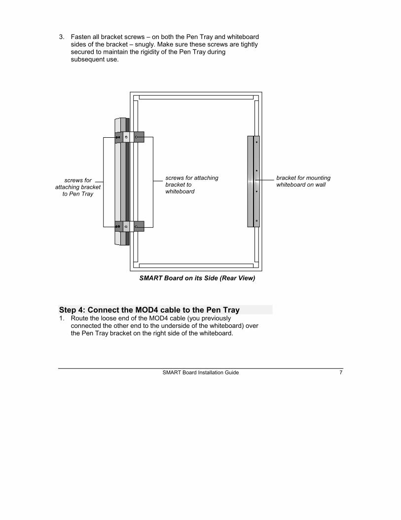
3. Fasten all bracket screws – on both the Pen Tray and whiteboardsides of the bracket – snugly. Make sure these screws are tightlysecured to maintain the rigidity of the Pen Tray duringsubsequent use.
Step 4: Connect the MOD4 cable to the Pen Tray1. Route the loose end of the MOD4 cable (you previously
connected the other end to the underside of the whiteboard) overthe Pen Tray bracket on the right side of the whiteboard.
SMART Board on its Side (Rear View)
screws forattaching bracket
to Pen Tray
screws for attachingbracket towhiteboard
bracket for mountingwhiteboard on wall

8 SMART Board Installation Guide
2. Connect the mini RJ11 connector end of the MOD4 cable to therectangular socket labeled “BOARD” that is located on the rightside of the Pen Tray (see the figure below).
Finding and Marking a Suitable LocationFLOOR STAND NOTE: This procedure, as well as the wall-mountingprocedures that follow, are unnecessary if the whiteboard is mounted ona floor stand. If you are mounting your whiteboard on a floor stand,proceed to “Connecting the Pen Tray to the Computer and PowerSource” on page 14.
Hardware Required• pencil
• measuring tape
• drywall mounting anchors (if needed)
• masking tape
mini RJ11 socket on end of Pen Tray
mini RJ11 connector
MOD4 cable
Connecting the MOD4 Cable to the Pen Tray

SMART Board Installation Guide 9
Step 1: Select an appropriate location for the SMARTBoard An ideal location is a portion of wall that is visible from all parts of
the room, uniformly flat, and capable of supporting the weight ofthe whiteboard.
If you intend to use the SMART Board with a projector, go to“Setting up a SMART Board with Projection” on page 18.Otherwise, proceed to Step 2 below.
Step 2: Mark the SMART Board location on the wall1. Determine the best height for comfortable writing and mark this
point on the wall.
2. Determine the size of the whiteboard, top to bottom and right toleft, by measuring its height and width, from the outer bezel onone side to the outer bezel on the other side.
3. Mark the wall to indicate the top of the whiteboard frame, keepingit well within reach of the mark made in step 1.
4. Using the length and width measurements determined in step 2,mark the external dimensions of the whiteboard frame on thewall.
Attaching the Wall BracketA pair of brackets are attached to the back of the whiteboard — onebracket (the wall bracket) is taped to the back of the whiteboard and theother is permanently fixed to the top of the whiteboard. You will removeonly the bracket that is taped to the whiteboard and mount it on the wall,slot facing up.
The down-facing slot on the bracket fixed to the whiteboard will slide intothe up-facing slot on the bracket you will attach to the wall, holding thewhiteboard in place.
.

10 SMART Board Installation Guide
Hardware required• measuring tape
• pencil
• wall bracket (to be removed from the back of the whiteboard)
• a bag (to be removed from the back of whiteboard) containing:
• four drywall mounting anchors
• four #8 x 1¼-inch Robertson pan-head screws
• Robertson screwdriver
Step 1: Preparation1. Remove the wall bracket and the bag (containing four drywall
mounting anchors and four #8 x 1¼-inch pan-head screws) tapedto the back of the whiteboard.
bracket fixed to the backof the whiteboard
wall-mounting bracketattached to the wall
Whiteboard Bracket Sliding into Wall Bracket

SMART Board Installation Guide 11
2. Mark a spot 2¼ inches or 57mm (the distance between the top ofthe whiteboard bezel and the bracket screws) down from the wallmark you made previously (indicating the top of the whiteboard).
3. Place the wall bracket horizontally against the wall (creating anup-facing slot), with the screw holes on level with the mark madein step 2 above.
4. Ensure that the wall bracket is level.
You can place a bubble level on top of the wall bracket and thenmake adjustments until it is completely level.
5. Insert a pencil into the four screw holes on the wall bracket,marking their locations on the wall.
Step 2: Attach the wall bracket to the wall1. If you are mounting the SMART Board on drywall, and if the screws
that will support the wall bracket will not be fastened to a supportingwall stud, insert the four drywall anchors as described below.
• Screw the drywall anchors into the wall with the Robertsonscrewdriver at the four spots just marked in step 5 above,keeping the shaft of the anchor very straight so that it entersthe wall at a right angle.
• Press firmly while turning the screwdriver until the drywallanchors are snug in the wall.
2. Place the wall bracket horizontally against the wall, with the openslot facing up.
3. Attach the wall bracket to the wall by inserting the four #8 x 1¼-inch screws through the holes in the bracket and tightening theminto the wall (or into the drywall anchors you installed above).
bracket on wall, withopen slot facing up
12 SMART Board Installation Guide
Mounting the SMART BoardTwo people are required to complete this procedure, one person standingat either side of the whiteboard. The weight of the whiteboard should besupported at the bottom corners and balanced at the top as it is lifted up,so that the bracket on the back of the whiteboard meets the open slot ofthe wall bracket.
“Step 2: Secure the Pen Tray to the wall” only needs to be performed ifthe whiteboard does not remain rigid and stationary when pressed alongits bottom edge.
Step 1: Mount the whiteboard on the wall1. Lift the whiteboard from its side-resting position to the top of the
open end of the wall bracket, making sure its weight is fullysupported at the bottom corners.
2. Lower the whiteboard onto the wall bracket, sliding the bracketon the back of the whiteboard down into the open slot of the wallbracket.
3. Ensure the whiteboard is securely fixed on the wall bracket byholding it firmly at both sides, and then attempting to pull it awayfrom the wall. If the whiteboard pulls away from the bracket, it isonly partially engaged. Lift the whiteboard up and slide it into thewall bracket again.
Step 2: Secure the Pen Tray to the wallPress the whiteboard along its bottom edge. If the whiteboardremains stationary, skip this procedure. If the whiteboard shifts, youshould attach the Pen Tray directly to the wall to entirely eliminate anywhiteboard movement.
To accomplish this, disconnect the MOD4 cable from the Pen Tray,remove the Pen Tray from its brackets, secure the brackets to the wall,and then reattach the Pen Tray to its brackets.
WarningAvoid resting thebottom of thewhiteboard againstthe floor as the PenTray could sustaindamage from itsweight.
SMART Board Installation Guide 13
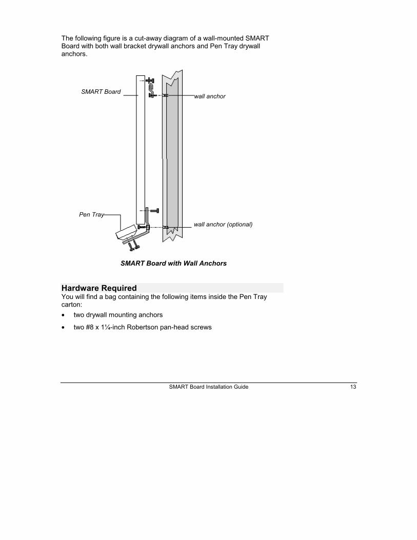
The following figure is a cut-away diagram of a wall-mounted SMARTBoard with both wall bracket drywall anchors and Pen Tray drywallanchors.
Hardware RequiredYou will find a bag containing the following items inside the Pen Traycarton:• two drywall mounting anchors
• two #8 x 1¼-inch Robertson pan-head screws
SMART Boardwall anchor
Pen Traywall anchor (optional)
SMART Board with Wall Anchors

14 SMART Board Installation Guide
1. Disconnect the mini RJ11 connector end of the MOD4 cable fromthe rectangular socket labeled “BOARD” on the right side of thePen Tray.
2. Detach the Pen Tray by removing the screws that fasten the PenTray to the Pen Tray mounting brackets at the bottom of the PenTray.
The Pen Tray brackets will remain attached to the whiteboard.
3. Use a pencil to mark the position of the two holes in the Pen Traybrackets that will secure the Pen Tray to the wall.
4. Rotate both Pen Tray brackets out of the way of the pencil marksjust made on the wall.
5. Insert a drywall anchor at each pencil mark, tightening until snugin the wall.
6. If the wall is uneven, “shim” the wall by inserting a thin slip orwedge of wood between the wall and the Pen Tray mountingbrackets to create an even surface for fastening the bottom ofthe whiteboard.
7. Rotate the Pen Tray brackets back in place over the drywallanchors. Then use the two Robertson pan-head screws to fastenthe Pen Tray mounting brackets to the drywall anchors. Tightento hold the whiteboard in place.
8. Reattach the Pen Tray to the Pen Tray brackets with the fourscrews you removed in Step 2.
9. Reconnect the MOD4 cable to the Pen Tray by reinserting themini RJ11 connector into the rectangular socket on the right sideof the Pen Tray labeled “BOARD”.
Connecting the Pen Tray to the Computerand Power SourceYou will now connect the Pen Tray to the computer and the power sourceto enable all parts of the SMART Board to communicate with each other.
ImportantKeep the Pen Traymounting bracketsstationary as youremove the screws.
WarningDo not force the Boardto fit an uneven wallsurface. This maycause the SMARTBoard to warp or bend,causing it tomalfunction andproduce a constantcontact (see glossary).
SMART Board Installation Guide 15
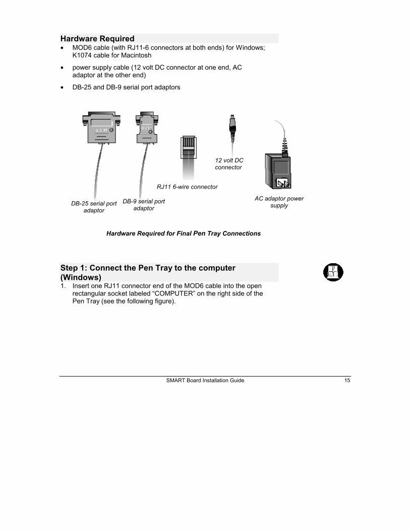
Hardware Required• MOD6 cable (with RJ11-6 connectors at both ends) for Windows;
K1074 cable for Macintosh
• power supply cable (12 volt DC connector at one end, ACadaptor at the other end)
• DB-25 and DB-9 serial port adaptors
Step 1: Connect the Pen Tray to the computer(Windows)1. Insert one RJ11 connector end of the MOD6 cable into the open
rectangular socket labeled “COMPUTER” on the right side of thePen Tray (see the following figure).
Hardware Required for Final Pen Tray Connections
12 volt DCconnector
RJ11 6-wire connector
AC adaptor powersupply
DB-9 serial portadaptor
DB-25 serial portadaptor

16 SMART Board Installation Guide
2. Determine if the vacant COM port on your computer requires aDB-25 or a DB-9 female connection by counting the pins in theCOM port.
A DB-25 COM port has 25 pins to connect with the 25 holes on aDB-25 cable; a DB-9 COM port has 9 pins to connect with the 9holes on a DB-9 cable.
3. Insert the remaining RJ11 connector end of the MOD6 cable intothe appropriate female serial port adaptor (DB-25 or DB-9).
4. Insert the serial port adaptor into the vacant COM port on thecomputer.
Step 1: Connect the Pen Tray to the computer(Macintosh)1. Insert the RJ11 connector end of the K1074 Macintosh cable into
the open rectangular socket labeled “COMPUTER” on the rightside of the Pen Tray (see figure above).
RJ11 socket on endof Pen Tray
RJ11 connector
MOD6 serial cable
Connecting the MOD6 Cable to the Pen Tray

SMART Board Installation Guide 17
2. Insert the barrel-shaped end of the cable into either the modemor printer port socket on the back of your Macintosh computer.
Inserting the Macintosh Cable into the Printer or Modem PortSocket
Step 2: Connect the Pen Tray to the power supply1. Insert the 12 volt DC end of the power supply cable into the
circular socket labeled “POWER” on the right side of the PenTray (see the following figure).
printer or modem port socket
Macintosh cable
rectangular Pen Tray sockets
Inserting the DC Connector into the Pen Tray Socket
12 volt DC connector
circular socket labeled“POWER”

18 SMART Board Installation Guide
2. Insert the AC adaptor end of the power supply cable into anearby power socket.
The Ready Light on the Pen Tray will flash twice and then turnoff. After you install and activate the SMART Board Software, theReady Light will come back on and remain on while the Board isin use.
Setting Up a SMART Board with ProjectionIf you are using a projector with the SMART Board, first set up theprojector on its stand, then adjust its projected image to a wall height thatis suitable for writing. Use the projected image as a guide to mark thewhiteboard location on the wall.
Activity OverviewTo set up the projector and position the SMART Board, you will:
1. Install the projector
2. Mark the SMART Board location
3. Match the computer resolution to the projector resolution
4. Adjust the projected image
Step 1: Install the projector on its stand1. Place the projector squarely on a table or projector stand, lens
facing forward.
2. Connect the projector’s power cable and turn the projector on.
Refer to your projector manual for further instructions onprojector use.
3. Move the projector right or left to center the image horizontally onthe screen.
4. To center the image vertically, you may need to raise or lower theprojector’s feet, or place it on a support beneath to raise it morethan the projector’s feet allow.
AC adaptor end of power
supply cable

SMART Board Installation Guide 19
Step 2: Mark the whiteboard position1. Determine a height at which the average person would feel
comfortable writing on a vertical surface, and mark this point onthe wall.
2. Measure the surface of the whiteboard, top to bottom and right toleft.
3. Using the writing height marked earlier as a guide, measure andmark a frame on the wall roughly the size of the whiteboard.
Step 3: Match computer resolution to projectorresolutionIn order for the on-screen image to properly fill the whiteboard screen, thecomputer and projector resolutions must be identical.
You should first ensure that the projector is set to its optimal imageresolution. Refer to your projector’s manual for the optimal resolution ofyour projector, and reset it if necessary. While these instructions mayindicate that resolutions other than the optimal one are permitted, don’talter the resolution to any of these other settings.
To set your Windows 95 computer resolution to match the projectorresolution:
1. Click the Windows 95 Start button and then point to Settings.
2. Point to the Control Panel folder and release the mouse button.
The Control Panel directory of folders will appear.
3. Double-click on Display.
The Display Properties dialog box will appear.
4. Click on the Settings tab.
5. In Desktop area, click and drag the sliding bar to adjust the pixelsetting to match the resolution of your projector.
6. Click the Apply and the OK buttons.
To set your Windows 3.1 or 3.11 computer resolution to match theprojector resolution:
1. Go to the Windows 3.1 Program Manager.
ImportantIf the resolution of theprojector is set toanything other than theoptimal resolution, or ifthe computer andprojector resolution donot match, you may beunable to see all of theimage on the SMARTBoard, or the imagethat appears may betoo small to properly fillthe SMART Board,even with furtheradjustments.
20 SMART Board Installation Guide
2. Double-click on the Main directory.
3. Double-click on the Windows Setup directory.
4. Select Change System Settings from the Options menu.
The Change System Settings dialog box will appear.
5. Scroll through the Display drop-down menu and select thesetting that matches the resolution of your projector.
6. Click OK.
To set your Macintosh computer resolution to match the projectorresolution:
1. Click on the Apple menu.
2. Click on Control Panels.
3. Select Monitors.
The Monitors dialog box will appear.
4. Click the Options button.
5. Go to the Select a monitor setting box and select the resolutionsetting that matches the resolution of your projector.
6. Click OK.
Step 4: Adjust the projected imageAdjust the projected image so that it fits within the frame marked out onthe wall, using any or all of the following methods to do so:
• Push the projector back until the image is approximately the rightsize (the further your projector is from the whiteboard, the largerits image).
• Increase or reduce the size of the projected image with the zoomlens.
• Raise or lower the feet of the projector.
• Use the projector’s software to make final adjustments after thewhiteboard is installed on the wall.
TipIf you move theprojector out of theway when the SMARTBoard is not in use,mark the location ofthe projector stand onthe floor with tape, ormeasure and make anote of its distancefrom the wall. Mark thelocation of theprojector on the standin the same way.

SMART Board Installation Guide 21
• Ensure that the projector is square to the walls (that is, parallel tothe front and side walls). If it isn’t square, the projected image willbe keystoned.
Continue the SMART Board installation process with “Attaching the WallBracket” on page 9. Keep the projector turned on to ensure thewhiteboard is mounted at the correct height for the projector.
WarningWhen mounting thewhiteboard, avoidlooking back directlyinto the projector lens,if the projector isturned on.
22 SMART Board Installation Guide
Installing SMART Board Software
SMART Board SoftwareEvery SMART Board is accompanied by two pieces of software: theSMART Board driver and SMART Notebook.
• The SMART Board driver activates your SMART Board, allowingyou to use your finger as a mouse, annotate over an application withelectronic ink, and use Board-aware applications.
SMART Aware™ is a Windows application that runs concurrently with theSMART Board driver. SMART Aware functions in the background tomake the whiteboarding component of six popular conferencingpackages Board-aware applications. In other words, the pens in theSMART Board Pen Tray do not just write over these applications withexternal annotations, but are recognized as integral programcomponents. In a conferencing situation, for example, theannotations you create on the SMART Board within a Board-awareconferencing program will be seen by other conference participants.
• SMART Notebook allows you to create, organize and save notes oneither a SMART Board or at your desktop, and then send those notesto a printer. A full range of annotation tools are available to enableyou to create a variety of annotations. You can also use Notebookcommands to export and import both graphics and text to and fromother Windows applications and your Notebook file.
Refer to the SMART Board User’s Guide and the online Help thataccompany each program for comprehensive instructions on how to usethe software. This section describes how to install these programs onyour computer. If you intend to install other software supplied by SMARTTechnologies, this is an opportune time to do so. See our Web site atwww.smarttech.com for upgrades and details about new software.
Windows System Requirements• personal computer with a 486 DX or higher processor
• 4 MB of memory required; 8 MB of memory recommended

SMART Board Installation Guide 23
• Windows 3.1 or 3.11, Windows 95, or Windows NT™ 3.51 or 4.0
• 4 MB of free hard disk space for complete (SMART Board) install
• an available serial port
Macintosh System Requirements• a 68030 or greater Macintosh or a Power Macintosh®
• 4 MB of memory required; 8 MB of memory recommended
• System 7®
• 4 MB of free hard disk space for complete (SMART Board) install
• An available modem or printer port
Software InstallationInstall the SMART Board Software disks directly onto the hard drive ofyour computer. SMART Board Software disks contain SMART Notebook,the SMART Board driver and SMART Aware (Windows only). Theseprograms can also be downloaded individually from our Web site atwww.smarttech.com.
Windows 95/ Windows NT 4.0 Installation1. Close all applications.
2. Insert the SMART Board Software disk into drive A.
3. From the desktop, click on Start, Run.
4. Type A:\Setup
5. Select OK.
6. Follow the remaining installation instructions as they appear onyour screen.
Windows 3.1/3.11 or Windows NT 3.51 Installation1. Start Windows.
2. Close all applications except Program Manager.
3. Insert the SMART Board Software disk into drive A.

24 SMART Board Installation Guide
4. Select File from the Run menu.
5. Type A:\Setup.
6. Select OK.
7. Follow the remaining installation instructions as they appear onyour screen.
NOTE for Users of Windows 3.x: You may need to install the Windows32-bit extensions, Win32s, before installing SMART Notebook. You willbe instructed to do so if SMART Notebook fails to detect Win32s on yoursystem during installation.
Macintosh InstallationSwitch on your Macintosh computer and install the SMART BoardSoftware disk as follows:
1. Insert the SMART Installation disk into your floppy drive.
2. Double-click the SMART Installer icon.
The SMART Installer window appears.
3. Click the Continue button to proceed with the installation.
4. You must now decide if you want a Normal Install or a CustomInstall. The Normal installation includes both SMART Notebookand the SMART Board driver programs.
Click the Install button to install both the SMART Notebook andSMART Board driver programs.
Click the Custom button to install either SMART Notebook orSMART Board driver.
5. If you chose the Custom Install, select which of the two programsyou want to install.
6. Follow the on-screen installation instructions to select adestination folder for the SMART Board Software.
SMART Board Installation Guide 25
Configuring and Orienting the SMARTBoardConfiguring the SMART Board involves specifying the COM port used tolink the computer to the SMART Board and indicating whether or not youare using a projector with the SMART Board.
If you are using the SMART Board with a projector, you must orient thecomputer image on the SMART Board. This orientation process ensuresthat the Board accurately tracks your finger or any Pen Tray tool.Orienting the SMART Board involves pressing on orientation pointsdisplayed on the screen. If the projected image becomes misaligned, youmust perform the orientation procedure again.
Configuring the SMART BoardThe first time you run the Board driver, you may need to ensure yourhardware connections are secure and then select a COM port for theSMART Board attached to your computer. At the end of this procedure,the Ready light on the Pen Tray will be lit, indicating an active SMARTBoard.
To select a COM port for the SMART Board:1. Choose Select Ports from the Board menu (from the Main
Menu or the Right Mouse menu).
or
Press the Select Ports button on the initial SMART Board screen.
The Check Board Connections dialog box will appear.
2. Ensure all hardware elements are securely connected.
3. Press the Next button.
The Pick a Port dialog box will appear.
4. If you know the COM port that is connected to your SMARTBoard, select it from the list of ports provided.

26 SMART Board Installation Guide
NOTE for Macintosh Users: The Macintosh Pick a Port dialogbox offers Modem Port and Printer Port selections. Click on theappropriate selection. Otherwise, proceed as outlined below,clicking Detect Boards to initiate the automatic detection of yourModem or Printer ports.
or
If you are not sure which COM port to select, press the DetectBoards button to initiate automatic SMART Board detection onlocal ports. At this point, you should close any other openprograms and save any unsaved work. The Auto Detect programwill inform you which COM port is connected to your SMARTBoard.
5. Press the Next button.
The Finished dialog box will appear.
6. Press the Done button.
The Ready Light on the Pen Tray will be illuminated.
You will only need to perform this configuration procedure againif your hardware configuration changes.
Orienting the Projected SMART BoardIf you are using a projector with your SMART Board, a check markshould appear beside the SMART Board Has a Projector selection inthe Board menu. A projected system enables you to use the Pen Traypens, your finger, or the drawing tools of the Floating Tool Palette to:
• annotate over applications that are not Board-aware (that do notrecognize Pen or Drawing Tool marks as integral programcomponents)
• perform application procedures within Board-aware programs
The projected computer image must be oriented to the Board. Withoutproper orientation, the cursor will not track your finger or a Pen Tray toolaccurately. Therefore, the first use of the activated SMART Board with aprojector should be performing the orientation procedure.
SMART Board Installation Guide 27
NOTE: If your Board is accidentally jostled and the projected imagebecomes misaligned, you may need to reorient. The quickest way to re-orient the Board is to click or press twice on the small SMART Board iconlocated in the System Tray (at the right side of the task bar).
To orient the SMART Board:1. Select Orient Board from the Board menu.
or
Press the Orient Board button on the initial SMART Boardscreen.
or
Click or press twice on the SMART Board icon in the SystemTray (connected SMART Board only).
or
Press the two Pen Tray buttons simultaneously (holding for at leastone second).
The Pick the Orientation Precision dialog box will appear.
2. Preview the three orientation levels − Quick, Standard and Fine −by clicking on the circle next to each heading.
Notice that the number of crosses in the miniature Board screen tothe left of these headings increases as you move down the list ofheadings.
The three orientation levels are described briefly below.
• The Quick orientation requires only 9 clicks to complete andis well-suited for fast orientations (e.g., when a Board isjostled during a presentation).
• The Standard orientation requires 20 clicks and provides alevel of accuracy suitable for most systems.
• The Fine orientation involves clicking on 80 individualcrosses. While the Fine setting is the most time-consumingto complete, it is recommended for higher-resolution systemsthat may require a more precise orientation.
3. Once you have determined the orientation level you prefer, selectit by clicking in the appropriate circle.

28 SMART Board Installation Guide
4. Click the Next button.
A large gray rectangular image will almost entirely fill the SMARTBoard screen. This screen will contain the number of crossesassociated with the orientation level chosen.
5. Follow the on-screen instructions, pressing your fingersquarely on the yellow center of each red cross, in the order specified by the large white arrow. To begin the orientation, press on the cross highlighted in red at the upper-left corner of the screen. You will hear a beep and the next cross in the series will be highlighted in red.
NOTE: If you press on the crosses out of sequence orinaccurately, a Bad Orientation Point dialog will appear. Tocorrect the bad orientation, select the OK button at the bottom ofthe screen using the mouse attached to your computer. This isnecessary because the system has lost Board-awareness whileorienting.
When you have pressed on the final cross, the Orientationscreen will disappear.
6. Test if the orientation was successful by moving your fingeracross the Board. The cursor should track your finger veryclosely and appear directly underneath the center of yourfingertip.
SMART Board Installation Guide 29
Customer Support
Contacting SMART Technical SupportAll SMART software includes one year of free telephone, fax, and e-mailsupport. You may contact SMART Technical Support at:
Telephone: (403) 228-8538(Available 7 AM - 6 PM Mountain Time from Monday to Friday)
Fax (24 hr.): (403) 245-0366E-mail: [email protected] site: www.smarttech.com
Please provide us with information about when you purchased theSMART Board, the dealer's name, your operating system, and the nameof the application software causing the problem, if applicable.
Other SMART ContactsSales and Marketing: (403) 245-0333Fax (24 hr.): (403) 245-0366E-mail: [email protected]
Our Address: SMART Technologies Inc.Suite 600, 1177 - 11th Avenue SWCalgary, AB CANADA T2R 1K9
WarrantyAll hardware products manufactured by SMART Technologies include aone-year parts and labor warranty. Customers must return any defectivemerchandise to an authorized service center as directed by thedistributor, dealer or manufacturer.

30 SMART Board Installation Guide
Warranty Shipping ChargesShipping charges incurred from warranty service are paid as follows: Thecustomer is responsible for shipping the system to the service center.SMART Technologies pays return shipping via ground service on anyproduct returned for service within the warranty period. Any chargesassociated with a customer-requested rush order are billed to thecustomer. Following the warranty period, the customer is responsible forshipping the product to and from the service center.
Read the warranty shipped with your SMART Board for details.
User Registration CardA User Registration Card is shipped with every SMART Board. Tofacilitate user support and to receive news and updates, fill in and mailthe card to SMART Technologies.

SMART Board Installation Guide 31
Appendix A: Glossary of TechnicalTermsBezel: A frame. A SMART Board is an interactive whiteboardsurrounded by a bezel.
Board-aware applications: Applications written to specifically takeadvantage of the features in a SMART Board. SMART 2000Conferencing and SMART Ideas are examples of Board-awareapplications.
COM port: Common abbreviation for communications port. Acommunication port is a socket on a computer to which peripheraldevices (such as mice and modems) that need to communicate withthe computer are connected.
Constant contact: The result of the top outer surface of the Boardbeing in continual contact with the surface beneath, causing theBoard to constantly sense a point of contact.
Keystone correction angle: The angle at which optics inside aprojector have been set to compensate for distortions caused byprojecting onto a surface at an angle.
Mini RJ11 connector: The connector end of a MOD4 cable. A closelook at a mini RJ11 connector will reveal four tiny contacts set intofour slots. May also be known as a telephone handset connector orRJ22.
MOD4 cable: A flat modular cable consisting of 4 wires covered in aprotective sheath. It connects the SMART Board to the Pen Tray.
MOD6 serial cable: A flat modular cable consisting of 6 wirescovered in a protective sheath. It connects two computers orperipheral devices to allow communication between them. With theSMART Board, this cable connects the Pen Tray to the computer.
Optimal resolution: The native resolution at which a projector has beendesigned to operate without software enhancement. A projector’s optimalresolution may be 640 X 480 pixels (VGA), 800 X 600 pixels (SVGA) or1024 X 768 pixels (XGA). Projectors may operate in other resolutions,but the quality of the projected image may suffer.
32 SMART Board Installation Guide
Resolution: The number of displayed pixels per inch. Commonresolutions are: 640 X 480 and 800 X 600.
RJ11-6 connector: The connector end of a MOD6 serial cable. Aclose look at an RJ11-6 connector will reveal six tiny contacts set intosix slots. May also be known as an RJ12.
Serial port adaptor, 25-pin: A device that accepts an RJ11-6connector at one end and connects to a DB25-pin serial port on acomputer at the other. The device allows physically differentcomponents to be connected to each other, enabling you to connectthe Pen Tray to the computer’s DB25 male serial port.
Serial port adaptor, 9-pin: A device that accepts an RJ11-6connector at one end and connects to a DB9-pin serial port on acomputer at the other. The device allows physically differentcomponents to be connected to each other, enabling you to connectthe Pen Tray to the computer.
Shimming: Inserting a thin slip or wedge of wood or other materialbetween two surfaces to fill them out or to create a level surface. Thepiece of wood or other material used to fill out or create the evensurface is known as a “shim.”
If the wall on which you are hanging your SMART Board is slightlyuneven, you must add a shim between the wall and the SMARTBoard Pen Tray mounting brackets to create an even surface towhich to fasten the bottom of the Board.
SMART Aware: Software that allows specific third party conferencingapplications, such as Microsoft NetMeeting and Intel ProShare, torecognize tools from the SMART Pen Tray as integral softwarecomponents. Aware enables you to extend the unique presentationcapabilities of the SMART Board to many other popular conferencingapplications.
SMART Board driver: The software that drives, or activates, aSMART Board. The software allows you to use your finger as amouse, annotate over an application with electronic ink, and useSMART Board-aware applications.
SMART Board Installation Guide 33
Index
AAdjusting the projected image, 20Attaching the Pen Tray brackets to
the Pen Tray, 4Attaching the Pen Tray to the
Whiteboard, 4Attaching the Wall Bracket, 9Attaching the wall bracket to the
wall, 11
CConfiguring the SMART Board, 25Connecting the MOD4 cable to the
Pen Tray, 7Connecting the MOD4 cable to the
whiteboard, 5Connecting the Pen Tray to the
computer (Macintosh), 16Connecting the Pen Tray to the
computer (Windows), 15Connecting the Pen Tray to the
Computer and Power Source, 14Connecting the Pen Tray to the
power supply, 17Constant contact, 14Customer Support, 29
DDrywall anchors, 8, 10, 11, 14
FFigures
Connecting the MOD4 Cable tothe Pen Tray, 8
Connecting the MOD6 Cable tothe Pen Tray, 16
Hardware Required for Final PenTray Connections, 15
Inserting the DC connector intothe Pen Tray socket, 17
Inserting the Macintosh Cableinto the Printer or Modem PortSocket, 17
Inserting the Mini RJ11Connector into theWhiteboard, 6
Mini RJ11 Connector in InsertionPosition, 5
MOD4 cable with mini RJ11 4-wire connector, 4
Pen Tray and Mounting Brackets,5
SMART Board on its Side (RearView), 7
SMART Board with WallAnchors, 13
Whiteboard Bracket Sliding intoWall Bracket, 10
Finding and Marking a SuitableLocation, 8
Fine orientation, 27
GGlossary, 31
IInstalling SMART Board Software,
22Installing the projector, 18
MMarking a SMART Board (with
projection) position, 19Marking the SMART Board location
on the wall, 9Matching computer resolution to
projector resolution, 19Mini RJ11 connector, 5, 6, 14

34 SMART Board Installation Guide
MOD4 cable, 5, 7, 12, 14MOD6 cable, 15Mounting the SMART Board, 12
OOrientation levels, 27Orienting the SMART Board, 26
PPen Tray
Attaching brackets, 4Attaching to the whiteboard, 4, 6Connecting to MOD4 cable, 7Connecting to the computer
(Macintosh), 16Connecting to the computer
(Windows), 15Connecting to the power supply,
17Securing to the wall, 12
Pen Tray brackets, 4, 14Pick the Orientation Precision
(dialog box), 27Projector
Installing on stand, 18Matching computer and projector
resolution, 19
QQuick orientation, 27
RRecommended tools, 4RJ11 connector, 15Robertson screwdriver, 4, 5, 10, 11
SSecuring the Pen Tray to the wall,
12
Selecting a COM Port for theSMART Board, 25
Setting Up a SMART Board withProjection, 18
Shimming the wall, 14SMART Aware, 22SMART Board
components, 3configuring, 25described, 1floor stand-mounted, 2installation steps, 3models available, 1orienting, 26
SMART Board driver, 1,22SMART Board Installation
Configuring the SMART Board,25
Finding and marking a location, 8Orienting the SMART Board, 26Software Installation, 23
SMART Notebook, 1, 2, 22Software Installation
Macintosh, 23Windows 3.1 or 3.11, 23Windows 95, 23
Standard orientation, 27System Requirements
Macintosh, 22Windows, 22
UUser Registration Card, 30
WWall bracket, 10Warranty, 29
Warranty Shipping Charges, 30

Suite 600, 1177 - 11th Avenue SW, Calgary, AB CANADA T2R 1K9Tel. (403) 245-0333 (Switchboard) Fax (403) 245-0366 e-mail: [email protected] www.smarttech.com
(403) 228-8538 (Support)
Printed in Canada