smart antenna inbroadband wireless accesss
TRANSCRIPT

8/14/2019 SMART ANTENNA INBROADBAND WIRELESS ACCESSS
http://slidepdf.com/reader/full/smart-antenna-inbroadband-wireless-accesss 1/27
1. INTRODUCTION
The rapid growth of the Internet user base and of bandwidth-hungry applications
in recent years has created a need for ‘last mile’ broadband access for residential and
business consumers. This demand for high-speed access is becoming a market force for
advanced broadband access technologies and networks.
We define “broadband” access as one that provides at least 5 Mbps peak (burst)
rate per user in the downlink direction and 500 Kbps peak (burst) rate in the uplink. The
average bit rates may be significantly lower in many applications. This bit rate
asymmetry arises because applications such as web browsing are asymmetric. The
growing demand for streaming audio and video will increase downlink throughput and
quality of service (QoS) requirements. Other applications such as telephony and video
conferencing need symmetric and constant bit rate services. Internet services and content
are evolving in ways hard to predict. The only predictable trend is that bit rates and QoS
requirements will increase rapidly.
Early applications of broadband access technologies were ‘big pipe’ applications
aimed at large offices and business campuses offering 10 to 100 Mbps connectivity.
However, new deployments increasingly target ‘small pipe’ volume markets such as
medium-sized businesses, SOHOs (Small Office/Home Office) and residential customers.
Broadband data access services are currently offered through a range of competing wired
(Digital Subscriber Line -xDSL, fiber to the home (FTTH), hybrid fiber coax (HFC) and
cable) and wireless (Multichannel Multipoint Distribution Service (MMDS), Local
Multipoint Distribution Service (LMDS), High Altitude Long Operation (HALO) and
satellite) technologies. Each approach has different cost structures, performance and
deployment trade-offs.
While cable and DSL are currently gaining momentum in the broadband access
marketplace, BWA is emerging as a third access technology with several advantages over
its wired counterparts. These include rapid deployment, high data (Mbps/sq.mile)
scalability, low maintenance and upgrade costs of the wireless facilities, and granular
Department of ECE Page 1Smart Antenna’s for BWA

8/14/2019 SMART ANTENNA INBROADBAND WIRELESS ACCESSS
http://slidepdf.com/reader/full/smart-antenna-inbroadband-wireless-accesss 2/27
investment to match market growth.
A typical BWA system uses radio hubs called base transceiver stations (BTS) to
serve a group of subscribers. The customer premises equipment (CPE) uses a rooftop
directional antenna. The licensed frequencies for BWA lie in the 24-48 GHZ band (e.g.,LMDS) or below the 5 GHz (e.g., MDS, WCS and MMDS bands). There are also a
number of unlicensed bands at 2.4, 5, 5.7, 24 and 38 GHz.
Despite the advantages of wireless access, there remain a number of critical issues
to be resolved before BWA can successfully penetrate the market. The chief concerns are
spectrum efficiency, network scalability, self-installable CPE antennas, and reliable non-
line of sight operation. Smart antennas (SA) offer a powerful tool to address these
problems.
SA is an emerging technology that has gained much attention over the last few
years for its ability to significantly increase the performance of wireless systems. SA is
being inserted into 2.5 generation (GSM-EDGE) and third generation (IMT 2000) mobile
cellular networks [1]. In this paper we outline why smart antennas constitute a
particularly good match for emerging BWA systems.
The rest of the paper is organized as follows. In the next section, we describe
BWA architectures and its challenges with emphasis on spectrum efficiency and on
scalability. In section 3, we give an overview of the leverages offered by smart antennas
in fixed BWA. We present a classification of smart antenna techniques and describe some
applications and performance value. Section 4 concludes the paper.
Department of ECE Page 2Smart Antenna’s for BWA

8/14/2019 SMART ANTENNA INBROADBAND WIRELESS ACCESSS
http://slidepdf.com/reader/full/smart-antenna-inbroadband-wireless-accesss 3/27
2. BIOGRAPHIES
2.1. KHURRAM SHEIKH
Khurram P. Sheikh ([email protected]) is currently the technical lead for
broadband wireless research and development at Sprint’s Advanced Technology Labs in
Burlingame, CA.
He is also completing his Ph.D. at Stanford University focused on broadband wireless
network systems utilizing space time processing, advanced QoS techniques and scalable
network architectures. Khurram joined Sprint in 1996 after completing his MSEE from
Stanford specializing in wireless communication systems, RF circuit design and
networking.
Over the past three years he has spearhead applied research activities at Sprint on
MMDS, LMDS, 3G/IMT-2000, Wireless ATM and next generation wireless LANs
technologies that have included technology/network design and architecture, simulation,
competitive technology analysis, lab prototyping and experimental field testing.
Khurram has earned many industry recognition awards for his technical contributions
and recently was inducted to the North American Who’s Who of Executives and
Professionals for the Millennium Edition 2000-2001.
Department of ECE Page 3Smart Antenna’s for BWA

8/14/2019 SMART ANTENNA INBROADBAND WIRELESS ACCESSS
http://slidepdf.com/reader/full/smart-antenna-inbroadband-wireless-accesss 4/27
2.2. DAVID GESBERT
David Gesbert ([email protected]) was born in Mantes-La-Jolie,
France, in 1969.
He received the M.Sc. degree in Electrical Engineering from National Institute
for Telecommunications (INT), Every, France, in 1993, and obtained the PhD degree
from Ecolab National Superior des Telecommunications (Telecom Paris), Paris , France,
in 1997.
From 1993 to 1997, he was with France Telecom, CNET , where he was involved
in the development and study of receiver algorithms for digital radio communications
systems, with emphasis on blind signal detection. Since April 1997, he has been a
postdoctoral fellow at the Smart Antenna Research Group of the Information Systems
Department of ECE Page 4Smart Antenna’s for BWA
M e g a c e l l t o
c o v e r l o w
d e n s i t y a r e a s
M a c r o c e l l s t o
c o v e r h i g h
d e n s i t y a r e a s
N o c o m m o n f r e q u e n c y b e t w
m e g a a n d m a c r o c e l l s
Figure 2.1 Overlay-Underlay Deployments

8/14/2019 SMART ANTENNA INBROADBAND WIRELESS ACCESSS
http://slidepdf.com/reader/full/smart-antenna-inbroadband-wireless-accesss 5/27
Laboratory, Stanford University.
From April 1997 to April 1998, he has been the recipient of a French Defense
DGA/DRET postdoctoral fellowship. In October 1998, he took part in the team of
founding employees of Gigabit Wire less, Inc, Mountain View, Ca., a startup company promoting high-speed wireless data networks using smart antennas.
His research interests are in the area of signal processing for digital
communications, blind array processing, smart antennas, multi-user communications, and
high-speed wireless networks.
2.3. DHANANJAY GORE
Dhananjay Gore ([email protected]) received his B.Tech degree from
the Indian Institute of technology, Bombay in 1998. He is currently a Ph.D. student in the
Smart Antennas Research Group at Stanford University.
His research interests are in the area of signal processing for communications and smart
antennas.
• Arogyaswami Paulraj
Arogyaswami Paulraj ([email protected]) is a Professor of Electrical
Engineering at Stanford University working in the area of mobile communications.
His interests are in design of second and third generation terrestrial and satellite
wireless networks. His particular focus is on use advanced signal processing and coding
at the physical layer.
Dr. Paulraj is the author of about 240 research papers and holds several patents.
He has won a number of awards for his contributions to research and development.
Department of ECE Page 5Smart Antenna’s for BWA

8/14/2019 SMART ANTENNA INBROADBAND WIRELESS ACCESSS
http://slidepdf.com/reader/full/smart-antenna-inbroadband-wireless-accesss 6/27
He served in the Indian Navy from 1961 to 1990, and contributed to the
development of sensor systems and high speed computing.
He is a Fellow of the Institute of Electrical and Electronics Engineers and is
affiliated with several other professional institutions.
\
Department of ECE Page 6Smart Antenna’s for BWA
b 1 b 6b 5b 4b 2 b 3 . . . .
b 1 b 4
. . .b 6b 3
b 2 b 5 . . .
. . .
S I G N A L P R O C E S S I N G
b 1 b 6b 5b 4b 2 b 3 . . . .
S I G N A L P R O C E S S I N G
b 2 b 5 . . .
b 2 b 5 . . .
. . .b 6b 3
C 1
C 3
C 2
A 1
A 3
A 2
B 3
B 2
B 1
A 1 C 1
B 3
B 2
B 1
A 3
A 2
C 3
C 2
Figure 2.2. Spatial Multiplexing opens multiple parallel channels.

8/14/2019 SMART ANTENNA INBROADBAND WIRELESS ACCESSS
http://slidepdf.com/reader/full/smart-antenna-inbroadband-wireless-accesss 7/27
3. BWA ARCHITECTURES AND CHALLENGES
In this section we first describe alternate architectures – single (mega) cell
currently proposed and macro cells being actively developed for BWA. We then describe
the main challenges faced by BWA technologies.
3.1. ARCHITECTURES
3.1.1. SINGLE (MEGA) CELL
In mega cell architecture, a large service area with a radius of up to 30 miles is
covered by one or two cells. The base station antenna is typically located on a very high
tower or hill top (height of 500 to 1200 ft) to provide line of sight (LOS) paths to
subscribers.
A high gain CPE rooftop mounted antenna pointing towards the base station is
used. Frequency reuse in angle (and polarization) may be possible with sectorization [Fig.
1(a)], particularly on the uplink.
The carrier to noise ratio (C/N) of around 25 to 33 dB needed for high order
modulation is sustained by the high antenna gains and low loss line of sight (LOS)
propagation.
Mega cells are possible only in the microwave bands because there is severe
foliage and rain attenuation in the milli metric bands that limit the range considerably.
Department of ECE Page 7Smart Antenna’s for BWA
8/14/2019 SMART ANTENNA INBROADBAND WIRELESS ACCESSS
http://slidepdf.com/reader/full/smart-antenna-inbroadband-wireless-accesss 8/27
Macro Cell
Macro cellular systems use spatial frequency reuse to cover the service area. The
BTS heights are similar to cellular infrastructure. Macro cells therefore typically use 4
QAM modulations, a spatial reuse factor of 3 to 4 and no angle reuse. LOS propagation is
usually not possible, and cell ranges are therefore much smaller (1 – 4 miles) due to
higher path loss.
The following table compares two different cellular architectures for BWA. In
practice, both systems may co-exist in an overlay - underlay deployment scenario [Fig.
2].
Department of ECE Page 8Smart Antenna’s for BWA
-10 0 10-10
-5
0
5
10A1
-10 0 10-10
-5
0
5
10A2
-10 0 10-10
-5
0
5
10A3
-0.5 0 0.5-0.6
-0.4
-0.2
0
0.2
Q u a d r a t u r e d a t a
B1
-0.5 0 0.5-0.1
0
0.1
0.2
0.3
Q u a d r a t u r e d a t a
B2
-0.5 0 0.5-0.4
-0.2
0
0.2
Q u a d r a t u r e d a t a
B3
-10 0 10-10
-5
0
5
10
In phase data
Q u a d
r a t u r e d a t a
C1
-10 0 10-10
-5
0
5
10
In phase data
Q u a d
r a t u r e d a t a
C2
-10 0 10-10
-5
0
5
10
In phase data
Q u a d
r a t u r e d a t a
C3
Figure 3.1. SM Experimental results: Three antennas with 64 QAM signals .A1,A2,A3: Transmitted constellations. B1, B2,B3: Rx constellations at antennas. C1,C2,C3: Separated constellations.

8/14/2019 SMART ANTENNA INBROADBAND WIRELESS ACCESSS
http://slidepdf.com/reader/full/smart-antenna-inbroadband-wireless-accesss 9/27
MEGA-CELL MACRO-CELL
No. of Cells One Multiple
BTS Antenna Height High(>500’) Low(~100’)
CPE Antenna height Rooftop (>30’) Medium(~15’)
Propagation LOS needed NLOS acceptable
Frequency Bands <5 GHz <5 GHz and millimetric
Reuse Angle Reuse Spatial Reuse
Coverage <30-40 miles <3-4 miles
Table3.2. Mega Cell vs Macro Cell Deployment
3.2. BWA CHALLENGES
The successful deployment of BWA technology faces a number of critical
challenges. These are discussed below.
3.2.1. CAPACITY/SPECTRUM EFFICIENCY
The rapid increase, both in access minutes and average bit rates, along with
limited radio spectrum calls for the development of networks with very high spectrum
efficiency. This is particularly acute in the downlink where higher bit rates (several Mbps
average throughput per square mile) are needed.
We can increase spectrum efficiency through aggressive frequency re-use and
higher order modulation. However, frequency reuse increases co-channel interference
and reduces modulation order. The spectral efficiency of a wireless network is measured
by bps/Hz/Cell (BHC). BHC is the bits per second delivered by one cell divided by the
total spectrum (Hz) in the network. BHC is a good measure based on the premise that
base stations are high cost items and throughput per base station is a key metric. Because
of the traffic asymmetry in BWA, the downlink BHC is a key figure of merit in BWA
Department of ECE Page 9Smart Antenna’s for BWA

8/14/2019 SMART ANTENNA INBROADBAND WIRELESS ACCESSS
http://slidepdf.com/reader/full/smart-antenna-inbroadband-wireless-accesss 10/27
networks.
In macro-cell (cellular) deployments, frequency reuse in a spatially separated cell
gives rise to co-channel interference (CCI) and depends on reuse factors and sectorization
plans.
In single cell systems frequency reuse in angle is the source of co-channel
interference and depends on side lobe leakage at BTS antennas and scattering from reuse
sectors [Fig 1(b)].
Assuming that co-channel interference can be treated as additive white gaussian
noise (AWGN), the classical Shannon’s formula can be rewritten to yield the theoretical
limit on BHC in a frequency reuse network:
where C/I is the signal to interference plus noise ratio, m is an overhead factor for
excess bandwidth and frequency guard bands, K is the spatial reuse factor and L is the
angle reuse factor.
In macro-cell systems, K is equal to the cluster size and L is one. In single cell
systems, L is the number of times a channel is reused in angle and K is one. The above
equation suggests that aggressive reuse (decreasing K in macro-cell architectures or
increasing L in single cell systems) would increase system capacity.
However, frequency reuse increases CCI, thereby reducing the C/I and
modulation order. C/I is approximately proportional to K 2 in macro-cell networks and 1/L
in single cell networks.
Department of ECE Page 10Smart Antenna’s for BWA
mK
C/I)Llog(1 += BHC

8/14/2019 SMART ANTENNA INBROADBAND WIRELESS ACCESSS
http://slidepdf.com/reader/full/smart-antenna-inbroadband-wireless-accesss 11/27
In general, BHC is maximized by aggressive reuse i.e. smaller K or larger L.
Optimum tradeoff of K, L and C/I depends on target BER, propagation conditions, C/N,
fading, antenna side lobes and diversity schemes. Single cell systems can have high
downlink BHC (3-6) because of LOS propagation and absence of interference. Macro
cell systems have much lower downlink BHC (0.15-0.5).
Another figure of merit is throughput density - bps/Hz/sq.mile (BHS). This metric
is independent of the number of base stations required, but captures the scalability in the
network to support increasing load. For a medium sized city with 300 square miles area a
single cell network has a low BHS (0.04), while a macro cell (one mile cell radius)
network has a higher BHS (0.15).
3.2.2. COVERAGE
During initial deployment stages, the load density can be very low(<0.1
Mbps/sq.mile). As the number of users and load per user increases, load density can grow
by two orders of magnitude.
Therefore, initially the network is likely to be coverage limited. With very high
BTS antennas, directional CPE antennas and LOS propagation, high coverage is indeed
possible (with mega cells). However, lower BTS antennas, and presence of foliage and
terrain blocking, good coverage can be a challenging task.
Department of ECE Page 11Smart Antenna’s for BWA
0 . 1
1 0 m i l e m e g a c e l l
5 m i l e m e g a c e l l
1 m i l e m a c r o c e l l w i t h S A
1 2 . 5
1 m i l e m a c r o c e l l
0 . 5 2 . 5
D e m a n d L o a d ( M b p s / s q . m i l e )
Y e a r
s e r v i c e a r e a l i m i t e d t o o n e c e l l
n o l i m i t o n s e r v i c e a r e a
Figure 3.3 Scalability of BWA technologies.

8/14/2019 SMART ANTENNA INBROADBAND WIRELESS ACCESSS
http://slidepdf.com/reader/full/smart-antenna-inbroadband-wireless-accesss 12/27
Therefore, coverage is a challenge for macro cell networks. Of course, when the
demand has grown to a point when cells have to be shrunk due to capacity reasons,
coverage problems become less important.
3.3. THROUGHPUT AND QOS
As the types of service grow, the demand for higher throughput and quality of
service (QoS) will increase. While spectrum efficiency is important, other factors such as
an efficient medium access control (MAC), link layer adaptation and control (LLC), data
and voice convergence, scheduling and queuing etc, become critical to ensure high
throughput and good QoS features such as bit rate guarantees, latency, delay jitter and
packet loss.
3.3.1. Other Challenges
• Coverage Reliability: Wireless links face significant attenuation from rain, foliage
and blocking by terrain features. BWA networks should provide better than 80%
coverage reliability to subscribers in the service area despite these problems.
• Demand Scalability: Assuming 800 homes per square mile, 80% areal coverage, 5%
market penetration, 20% active subscribers and 50 Kbps average load per user, the
estimated load is 0.15 Mbps/sq.mile.
• As the market penetration increases to 20% and per subscriber load increases to 400
Kbps, the load per square mile may grow to 10 Mbps/sq.mile. Mega cell systems
have large coverage but limited capacity. A mega cell with a 10 mile radius and 50
MHz spectrum can support about 0.2 Mbps/sq.mile. Therefore, it barely covers the
initial load demand.
• The situation is better in a smaller city with a 5 mile radius mega cell where the
system can scale to 0.8 Mbps/sq.mile. However, mega cell systems must cover theentire service area and therefore are either limited to very thin load large cells or
medium load small cells.
• The situation is much better with macro cells where a one mile cell can scale to 1.5
Mbps/sq.mile. This can be even higher with smaller cells. In addition, macro cell
Department of ECE Page 12Smart Antenna’s for BWA

8/14/2019 SMART ANTENNA INBROADBAND WIRELESS ACCESSS
http://slidepdf.com/reader/full/smart-antenna-inbroadband-wireless-accesss 13/27
systems can cover any amount of service area by simply extending the cellular
network, a feature not possible in mega cells.
• Reuse of cellular infrastructure: Significant investments have been made in existing
PCS/cellular infrastructure. A BWA system should maximally reuse suchinfrastructure.
• Wire line Equivalent Availability: BWA systems should provide greater than
99.99% availability to match broadband wire line networks.
3.4. SMART ANTENNAS
There are two types of smart antennas. These two basic types include switched
multibeam antennas and adaptive array antennas. They are also known as directed
antennas and multiple input multiple output antennas respectively. The goal of a smart
antenna is to direct its focus in the direction of the incoming signal to increase signal
strength and distance. The other goal of smart antennas is to minimize interference both
from outsides sources and on outside sources. If a smart antenna is directed in a single
direction, all the nodes in the surrounding area, in the case of a wireless ad hoc network,
will not be limited in the transmissions they can send. They will be still free to continue
communicating.
3.5. MULTIBEAM ANTENNAS
The two types of smart antennas are remarkably similar in their original construct. Each
smart antenna has multiple antennas that connect to the main node. However, in the case
of the switched multi beam antenna, the node implements an algorithm to switch from
one antenna to another, depending on the location of the incoming signal. At any given
time, there will only be one antenna transmitting with the surrounding nodes. Beyond the basic concept of a directed antenna, there are two specific types of multi beam antennas.
The set up described above is a switched multi beam antenna. It switches between the
antennas so that the focused antenna is the antenna with the best signal. Another type of
Department of ECE Page 13Smart Antenna’s for BWA

8/14/2019 SMART ANTENNA INBROADBAND WIRELESS ACCESSS
http://slidepdf.com/reader/full/smart-antenna-inbroadband-wireless-accesss 14/27
directed antenna is the steered multi beam antenna, in which the node can actually steer
the antenna in the direction of the best signal. [2] These two types are show in Figure 3.
Figure 3.4: concept versions of a) switched multi beam antenna b) steered mult ibeam
antenna
3.6. ADAPTIVE ARRAY
Winters [1] suggests that an adaptive array antenna weighs each of the signals coming in
through the multiple antennas and selects a combination that will produce the best signal.
This approach is known as MIMO, or Multiple Input and Multiple Output
antennas. When thinking about an adaptive array like a linear array, the antennas can
send out and receive multiple packets at one time.
As shown in Figure 4, there is a higher throughput for these types of smart
antennas because each piece of a packet has a different channel on which to travel.
Instead of having to send a packet one piece at a time, which could get tied up if a packet
is dropped somewhere a long the line due to resends, an adaptive array can send all the
packets at once, and if one gets dropped it can be rectified promptly after the original
send. Packets get sent faster and more efficiently with adaptive arrays.
Department of ECE Page 14Smart Antenna’s for BWA
(b)(a)

8/14/2019 SMART ANTENNA INBROADBAND WIRELESS ACCESSS
http://slidepdf.com/reader/full/smart-antenna-inbroadband-wireless-accesss 15/27
Figure 3.5: Sending a packet through MIMO
The two important benefits of adaptive arrays are that they provide spatial multiplexing,
or the ability to send and receive multiple elements on a particular link and that an
adaptive array link can is more reliable because the error rate is decreased. [4] However,
these two benefits cannot be maximized at the same time.
Either a link can maximize the multiple streams of data being sent from the array
elements or it can maximize the reliability of the data channel for each of those elements.
The link quality is significantly improved with MIMO antennas due to the fact that it is
not likely that each of the array elements will experience a bad connection at the same
time and all the pieces of the packet will fail to send.
Since this is one of the biggest problems with SISO antennas, the implementation
of MIMO antennas on wireless ad-hoc networks will greatly increase the reliability of
each connection.
Department of ECE Page 15Smart Antenna’s for BWA
P1
P2
P3
P4
P5
P6
Packet
P1 P2 P3 P4 P5 P6

8/14/2019 SMART ANTENNA INBROADBAND WIRELESS ACCESSS
http://slidepdf.com/reader/full/smart-antenna-inbroadband-wireless-accesss 16/27
3.7. IMPROVING PERFORMANCE
In current ad-hoc networks, each node has an omni directional antenna that is constantly
searching for an incoming signal from the surrounding nodes. This antenna’s range
encompasses a certain circumference around the node. However, since this antenna’s
range is so large, it is a hindrance when multiple nodes are trying to transmit at the same
time. To correct this problem, the notion of a directional antenna was introduced to
wireless ad-hoc networks.
The directional antenna has a main lobe, which points in the direction of the node
with which the original node is trying to transmit. Since this becomes a directed beam,
not only does the signal strength increase, it also clears up the transmission channels for
nodes that were otherwise blocked by the omni directional antenna. This directional
antenna also has two side lobes in addition to the main lobe to keep nodes that are too
close to the original node from transmitting within a certain distance of the original node.
That way, there is no chance of interference or interruptions in the original transmission.
This is the concept of spatial reuse, or using the space that was previously tied up by an
omni directional antenna.
Figure 3.6: A directional antenna including side lobes and main lobes
The advantage of using a directional antenna is that since the beam for transmission and
reception is directed in a particular direction, the signal strength can be increased. The
gain no longer has to be spread out over a particular circumference, but can be focused in
Department of ECE Page 16Smart Antenna’s for BWA
AB
C
D
8/14/2019 SMART ANTENNA INBROADBAND WIRELESS ACCESSS
http://slidepdf.com/reader/full/smart-antenna-inbroadband-wireless-accesss 17/27
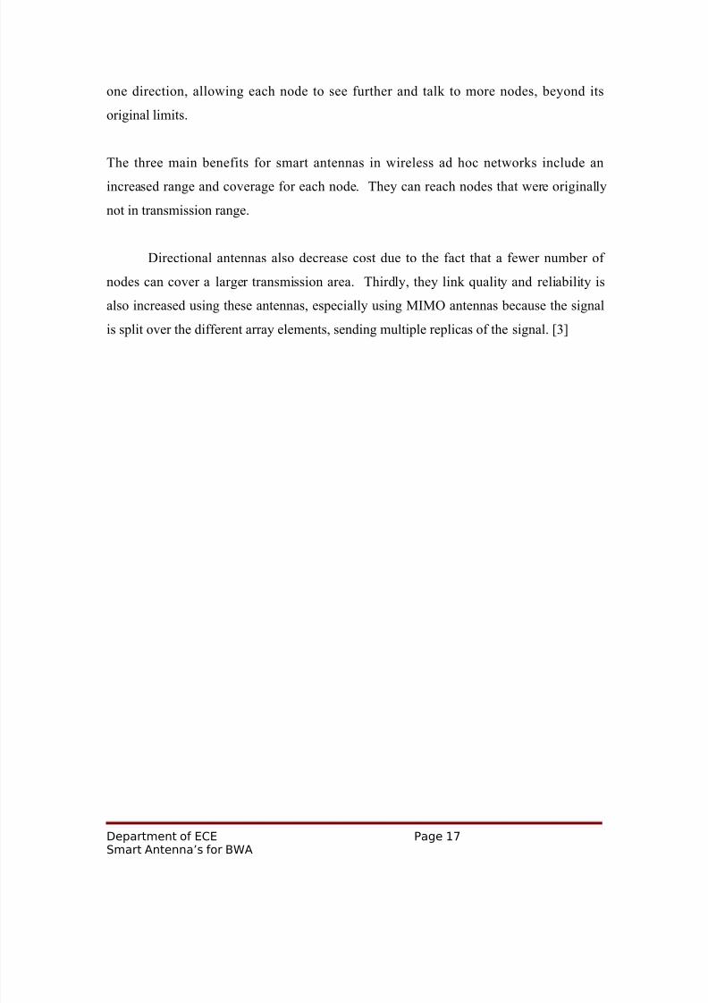
one direction, allowing each node to see further and talk to more nodes, beyond its
original limits.
The three main benefits for smart antennas in wireless ad hoc networks include an
increased range and coverage for each node. They can reach nodes that were originally
not in transmission range.
Directional antennas also decrease cost due to the fact that a fewer number of
nodes can cover a larger transmission area. Thirdly, they link quality and reliability is
also increased using these antennas, especially using MIMO antennas because the signal
is split over the different array elements, sending multiple replicas of the signal. [3]
Department of ECE Page 17Smart Antenna’s for BWA

8/14/2019 SMART ANTENNA INBROADBAND WIRELESS ACCESSS
http://slidepdf.com/reader/full/smart-antenna-inbroadband-wireless-accesss 18/27
4. SMART ANTENNAS
This section introduces the principles of smart antennas and discusses the
leverages offered by this technology.
4.1. SMART ANTENNAS IN BWA
BWA provides special opportunities for application of SA technology. These are:
• Very high data rates (100 times that of cellular voice in burst mode) need high
spectrum efficiency. SA can increase spectrum efficiency dramatically.
• Fixed data modems (or future portable services to lap-tops) allow the use of multiple
antennas at the CPE. Coupled with multiple BTS antennas, powerful SA leverages are
possible. In contrast, multiple antenna schemes are usually not practical in the cellular
phone.
• Downlink – uplink asymmetry emphasizes downlink spectrum efficiency. Multiple
antennas at the CPE enable high downlink performance.
• Low channel variability in fixed radio networks enables good channel estimation.
This is key to successful SA exploitation.
• In fixed applications, the CPE is line powered and additional power typically needed
by SA technology is not a constraint.
• BWA systems are expected to compete in quality and availability with wire line
networks. SA technologies (in particular diversity) improve quality/availability.
•
We now give an overview of SA applications for BWA. We assume that the CPE
and BTS has multiple (3~4) antennas. The antenna element specifications and array
topology at each end are chosen to maximize SA performance.
Department of ECE Page 18Smart Antenna’s for BWA

8/14/2019 SMART ANTENNA INBROADBAND WIRELESS ACCESSS
http://slidepdf.com/reader/full/smart-antenna-inbroadband-wireless-accesss 19/27
4.2. FUTURE RESEARCH DIRECTIONS
With the new capabilities of directional antennas, there comes the problem with
the old MAC layer channel access protocol. Previously, SISO antennas that listened
omni directionally used a CSMA/CD protocol which is a Carrier Sense Multiple Access
with Collision Detection protocol. This protocol required a three way handshake
between two nodes, and after exchanging acknowledgements, the two nodes would block
out their respective transmission fields and start sending data back and forth. They would
not free up their transmission fields until the last packet was sent. Any node that wanted
to start sending to a node that was in the transmission field, whether it is the node that is
currently sending or anything in the range of that node, when they send the first leg of the
handshake, an acknowledgement will not be sent, preventing the new node from sending
data.
However, with directional antennas, since the nodes are no longer blocking off the
entire sphere of transmission, and are instead only blocking off a single cone, this
approach no longer works efficiently because it is possible for two nodes in another
nodes transmission sphere to transmit back and forth if the third nodes directional beam is pointed in another direction. This requires a new protocol that allows for a way for two
node “neighbors” to discover each others location, to see if they are in each others
transmission radius, and a directional MAC protocol. [5] There are a variety of proposed
solutions that trade off reliability and transmission power and it is a large field to explore.
Department of ECE Page 19Smart Antenna’s for BWA
8/14/2019 SMART ANTENNA INBROADBAND WIRELESS ACCESSS
http://slidepdf.com/reader/full/smart-antenna-inbroadband-wireless-accesss 20/27
5. SMART ANTENNA APPLICATIONS
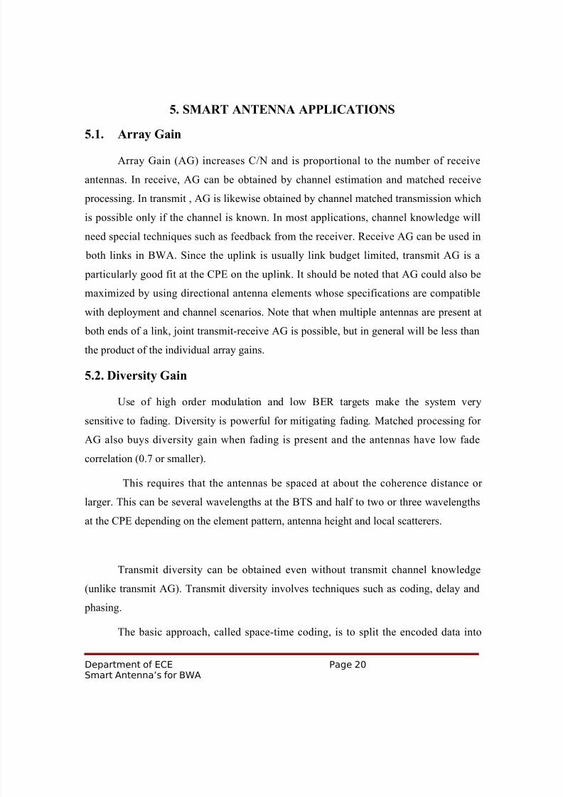
5.1. Array Gain
Array Gain (AG) increases C/N and is proportional to the number of receive
antennas. In receive, AG can be obtained by channel estimation and matched receive
processing. In transmit , AG is likewise obtained by channel matched transmission which
is possible only if the channel is known. In most applications, channel knowledge will
need special techniques such as feedback from the receiver. Receive AG can be used in
both links in BWA. Since the uplink is usually link budget limited, transmit AG is a
particularly good fit at the CPE on the uplink. It should be noted that AG could also bemaximized by using directional antenna elements whose specifications are compatible
with deployment and channel scenarios. Note that when multiple antennas are present at
both ends of a link, joint transmit-receive AG is possible, but in general will be less than
the product of the individual array gains.
5.2. Diversity Gain
Use of high order modulation and low BER targets make the system very
sensitive to fading. Diversity is powerful for mitigating fading. Matched processing for
AG also buys diversity gain when fading is present and the antennas have low fade
correlation (0.7 or smaller).
This requires that the antennas be spaced at about the coherence distance or
larger. This can be several wavelengths at the BTS and half to two or three wavelengths
at the CPE depending on the element pattern, antenna height and local scatterers.
Transmit diversity can be obtained even without transmit channel knowledge
(unlike transmit AG). Transmit diversity involves techniques such as coding, delay and
phasing.
The basic approach, called space-time coding, is to split the encoded data into
Department of ECE Page 20Smart Antenna’s for BWA

8/14/2019 SMART ANTENNA INBROADBAND WIRELESS ACCESSS
http://slidepdf.com/reader/full/smart-antenna-inbroadband-wireless-accesss 21/27
multiple data streams, each of which is modulated and simultaneously transmitted from a
different antenna. Different choices of data to antenna mapping can be used. All antennas
can use the same modulation and carrier frequency.
Alternatively, different modulation (symbol waveforms) or symbol delays can
also be used. Space-time codes can be block or trellis based, offering a range of
performance/complexity trade-offs [3]. BWA systems will typically use transmit and
receive diversity in both links.
5.3. CO-CHANNEL INTERFERENCE REDUCTION
Suppression of interference when the desired signal and co-channel interfering
signals have different spatial signatures is a powerful tool. Receive interference reduction
at the CPE on the downlink allows aggressive reuse of the spectrum. In transmit,
interference suppression capability depends on how well the desired user and co-channel
users can be differentiated at the transmitter which depends on channel knowledge. The
goal is to enhance the signal of the intended receiver and minimize the energy sent
towards co-channel users
5.4. ANGLE REUSE
Frequency reuse in angle [also known as Spatial Division Multiple access
(SDMA)] exploits beam forming/directional antennas to support more than one user in
the same frequency channel. Signal separation of co-channel beams has to be
accomplished at the BTS for both transmit and receive, since the CPE with a single
antenna has no signal separation capability. Angle reuse has not been a successful
technology in cellular networks because heavy scattering and mobility makes signal
separation impractical particularly on the downlink. However, in BWA mega-cells due to
high BTS antennas, the inter-sector scattering is small and angle reuse may be possible. If
the BWA systems use higher order modulation schemes that require large C/I (~30 dB)
angle reuse is still challenging and may need substantial SA complexity. With lower
order modulation (4 QAM), angle reuse may be possible. Typically, mega cell systems
Department of ECE Page 21Smart Antenna’s for BWA
8/14/2019 SMART ANTENNA INBROADBAND WIRELESS ACCESSS
http://slidepdf.com/reader/full/smart-antenna-inbroadband-wireless-accesss 22/27
use angle reuse (or Sdma) on the Uplink With 4 Qam Modulation.
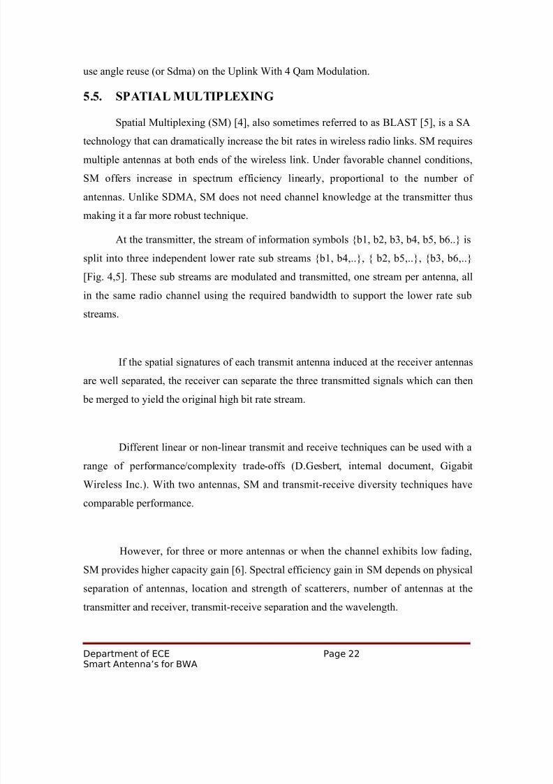
5.5. SPATIAL MULTIPLEXING
Spatial Multiplexing (SM) [4], also sometimes referred to as BLAST [5], is a SA
technology that can dramatically increase the bit rates in wireless radio links. SM requires
multiple antennas at both ends of the wireless link. Under favorable channel conditions,
SM offers increase in spectrum efficiency linearly, proportional to the number of
antennas. Unlike SDMA, SM does not need channel knowledge at the transmitter thus
making it a far more robust technique.
At the transmitter, the stream of information symbols {b1, b2, b3, b4, b5, b6..} is
split into three independent lower rate sub streams {b1, b4,..}, { b2, b5,..}, {b3, b6,..}
[Fig. 4,5]. These sub streams are modulated and transmitted, one stream per antenna, all
in the same radio channel using the required bandwidth to support the lower rate sub
streams.
If the spatial signatures of each transmit antenna induced at the receiver antennas
are well separated, the receiver can separate the three transmitted signals which can then
be merged to yield the original high bit rate stream.
Different linear or non-linear transmit and receive techniques can be used with a
range of performance/complexity trade-offs (D.Gesbert, internal document, Gigabit
Wireless Inc.). With two antennas, SM and transmit-receive diversity techniques have
comparable performance.
However, for three or more antennas or when the channel exhibits low fading,
SM provides higher capacity gain [6]. Spectral efficiency gain in SM depends on physical
separation of antennas, location and strength of scatterers, number of antennas at the
transmitter and receiver, transmit-receive separation and the wavelength.
Department of ECE Page 22Smart Antenna’s for BWA

8/14/2019 SMART ANTENNA INBROADBAND WIRELESS ACCESSS
http://slidepdf.com/reader/full/smart-antenna-inbroadband-wireless-accesss 23/27
In practice, antenna degrees of freedom have to be allocated across a number of
competing needs such as diversity, CCI cancellation and SM. Ideally, the product of the
number of antennas at the CPE and at the BTS represent the total number of degrees of
freedom available for combining purposes.
These degrees of freedom can be allocated freely, under ideal channel conditions,
to any of the leverages above.
5.6. CHANNEL ESTIMATION
SA techniques need accurate channel knowledge to be implementable. On
receive, the channel can be directly estimated since the transmitter can embed training
sequences that can be exploited by the receiver.
Simple transmit techniques such as beam forming for array gain need only
approximate channel knowledge [i.e. general direction of subscriber].
More complex transmits interference avoidance techniques need accurate channel
estimation. Two techniques are available: reciprocity and feedback.
The performance of these techniques depends on a number of factors such as the
duplexing technique and doppler spread of the channel (see [2] for further discussion).
Department of ECE Page 23Smart Antenna’s for BWA

8/14/2019 SMART ANTENNA INBROADBAND WIRELESS ACCESSS
http://slidepdf.com/reader/full/smart-antenna-inbroadband-wireless-accesss 24/27

8/14/2019 SMART ANTENNA INBROADBAND WIRELESS ACCESSS
http://slidepdf.com/reader/full/smart-antenna-inbroadband-wireless-accesss 25/27
6.1. PERFORMANCE ADVANTAGES
SA technology offers many advantages in BWA networks including improved BHC
and BHS, coverage and deployment improvements.
We believe that SA technology can yield a BHC of 2.5 bps/Hz/cell and a BHS of
0.8 bps/Hz/sq.mile (one mile cell). With 50 MHz of spectrum the demand scalability
reaches 12.5 Mbps/sq mile.
Smart Antenna macro cells therefore offer excellent scalability and economics.
Fig. [6] shows the scalability of different BWA technologies.
Department of ECE Page 25Smart Antenna’s for BWA
8/14/2019 SMART ANTENNA INBROADBAND WIRELESS ACCESSS
http://slidepdf.com/reader/full/smart-antenna-inbroadband-wireless-accesss 26/27
7. CONCLUSION
A large market opportunity is opening up for providing broadband wireless access
to residential, SOHO and business markets. Successful BWA systems need to be
scalable, should have high spectrum efficiency, should offer high bit rates and should be
easy to deploy at the infrastructure and subscriber end.
SA technology offers significant leverages to enable such features. Use of
multiple antennas at both ends of the wireless link along with efficient modulation, radio
resource management, coding and diversity can increase spectrum efficiency by a factor
of three to ten while greatly enhancing other desirable the capabilities of SA technology
without sacrificing robustness, simplicity and cost features. The challenge is to develop
and deliver a well designed BWA system that capture
Department of ECE Page 26Smart Antenna’s for BWA

8/14/2019 SMART ANTENNA INBROADBAND WIRELESS ACCESSS
http://slidepdf.com/reader/full/smart-antenna-inbroadband-wireless-accesss 27/27
8. REFERENCES
[1] Proceedings of the First, Second, Third, Fourth, Fifth and Sixth Annual Workshops
on Smart Antennas for Wireless Communications, Stanford University, Stanford Ca, July
1994 to July 1999.
[2] A. Paulraj and C. Papadias, “Space-time processing for wireless communications”,
IEEE Signal Processing Magazine, Nov. 1997, pp. 49-83.
[3] V. Tarokh, N. Seshadri and A. Calderbank, “Space time codes for high data rates
wireless communications. Performance criterion and code construction.” IEEE Trans. on
Info. Theory, vol. 44, March 1998, pp. 744-65.
[4] A. Paulraj et al., “Increasing capacity in wireless broadcast system using distributedtransmission/directional reception”, U.S. Patent, no. 5,345,599, 1994.
[5] G. Foschini and M. Gans, “On limits of wireless communications in a fading
environment when using multiple antennas”, Wireless Personal Comm., vol. 6, no. 3,
March 1998, pp. 311-35.
[6] R. W. Heath Jr., D.Gesbert, and A. Paulraj, “Maximizing spectral efficiency in
multiple-input multiple-output antenna systems”, Proc. of XXVIth International Union of
Radio Science (URSI ’99), Toronto, Canada, August 13-21, 1999, pp. 261.
[7] S. Alamouti, “A simple transmitter diversity technique for wireless communications”,
IEEE Journal on Selected Areas in Communications (Special Issue on Signal Processing
for Wireless Communications), Oct. 1998, vol. 16, no. 8, pp. 1451-8.
[8] J. Proakis, Digital Communications, Third Ed., McGraw-Hill, New York, 1995.
Department of ECE Page 27