small-cell installation in transportation infrastructure a
TRANSCRIPT
CIVIL ENGINEERING STUDIES Illinois Center for Transportation Series No. 20-004
UILU-ENG-2020-2004 ISSN: 0197-9191
Small-Cell Installation in
Transportation Infrastructure—
A Literature Review
Prepared by
Mohammad Imran Hossain Mohammad Ammar Alzarrad
Kristy Wolfe Suruz Miah
Bradley University
Research Report No. FHWA-ICT-20-003
A report of the findings of
ICT PROJECT R27-SP41 Small-Cell Installation in Transportation Infrastructure—
A Literature Review
https://doi.org/10.36501/0197-9191/20-004
Illinois Center for Transportation
January 2020

TECHNICAL REPORT DOCUMENTATION PAGE
1. Report No. FHWA-ICT-20-003
2. Government Accession No.
N/A
3. Recipient’s Catalog No.
N/A
4. Title and Subtitle
Small-Cell Installation in Transportation Infrastructure—A Literature Review
5. Report Date
January 2020
6. Performing Organization Code
N/A
7. Authors
Mohammad I. Hossain (https://orcid.org/0000-0003-4997-786X), Mohammad A. Alzarrad (https://orcid.org/0000-0002-6012-5679), Kristy Wolfe, and Suruz Miah (https://orcid.org/0000-0001-6533-0770)
8. Performing Organization Report No.
ICT 20-004
UILU-ENG-2020-2004
9. Performing Organization Name and Address
Illinois Center for Transportation
Department of Civil and Environmental Engineering
University of Illinois at Urbana-Champaign
205 North Mathews Avenue, MC-250
Urbana, IL 61801
10. Work Unit No.
N/A
11. Contract or Grant No.
R27-SP41
12. Sponsoring Agency Name and Address
Illinois Department of Transportation (SPR)
Bureau of Research
126 East Ash Street
Springfield, IL 62704
13. Type of Report and Period Covered
Final Report 9/1/19–1/31/20
14. Sponsoring Agency Code
15. Supplementary Notes
Conducted in cooperation with the U.S. Department of Transportation, Federal Highway Administration.
https://doi.org/10.36501/0197-9191/20-004
16. Abstract The purpose of this report is to provide information to the Illinois Department of Transportation (IDOT) on small-cell deployment on infrastructure such as light poles and traffic signals. A literature review was conducted on the technical specifications and impacts of small-cell deployment. The report explores the use of small-cell systems and potential hazards of small-cell deployment from an electromagnetic field perspective. A survey was conducted to gather information at a state and local level on current and future trends of small-cell deployment. The information gathered from the survey was combined from a standpoint of current best practices. The report provides recommendations for contractual obligations for both the department of transportation (DOT) and the small-cell provider. The report also provides guidelines on the best locations for small cells from a functional, structural, and aesthetic standpoint. The conclusion is that small-cell deployment is in our near future and the benefits of this technology are broad and mostly unexplored. While challenges exist, with proper contractual risk mitigation, both DOT entities and small-cell providers can reap benefits from the expansion of technology.
17. Key Words
Contracts, Federal Communications Commission, Infrastructures, Small Cell, Safety, Transportation
18. Distribution Statement
No restrictions. This document is available through the National Technical Information Service, Springfield, VA 22161.
19. Security Classif. (of this report) Unclassified
20. Security Classif. (of this page)
Unclassified
21. No. of Pages
74
22. Price
N/A
Form DOT F 1700.7 (8-72) Reproduction of completed page authorized

i
ACKNOWLEDGMENT, DISCLAIMER, MANUFACTURERS’ NAMES
This publication is based on the results of ICT-R27-SP41: Small-Cell Installation in Transportation Infrastructure—A Literature Review. ICT-R27-SP41 was conducted in cooperation with the Illinois Center for Transportation; the Illinois Department of Transportation; and the U.S. Department of Transportation, Federal Highway Administration.
Members of the Technical Review Panel (TRP) were the following:
• Mark Seppelt, TRP Chair, IDOT Bureau of Design and Environment
• Marshall Metcalf, TRP Co-Chair, IDOT Bureau of Operations
• Melvin Eze, IDOT Bureau of Design and Environment
• Trevor Hanson, IDOT District 4
• Annie Kuczkowski, Clanton & Associates, Inc.
• Tom Kurtenbach, IDOT Bureau of Bridges and Structures
• James Kyte, FHWA Springfield Division Office
• Mohammed Rashed, EJM Engineering, Inc.
• Frank Sharpe, IDOT Bureau of Bridges and Structures
• Megan Swanson, IDOT Bureau of Research
The authors would like to acknowledge Illinois Center for Transportation director Dr. Imad Al-Qadi for providing valuable insight into the project. The authors are grateful for the efforts of Bradley University undergraduate students Courtney Keys, Megan Spaunhorst, Austin Dial, and Nathaniel Merrill.
The contents of this report reflect the view of the authors, who are responsible for the facts and the accuracy of the data presented herein. The contents do not necessarily reflect the official views or policies of the Illinois Center for Transportation, the Illinois Department of Transportation, or the Federal Highway Administration. This report does not constitute a standard, specification, or regulation.
Trademark or manufacturers’ names appear in this report only because they are considered essential to the object of this document and do not constitute an endorsement of product by the Federal Highway Administration, the Illinois Department of Transportation, or the Illinois Center for Transportation.
ii
EXECUTIVE SUMMARY
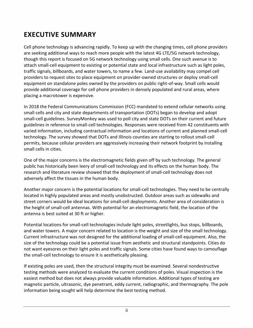
Cell phone technology is advancing rapidly. To keep up with the changing times, cell phone providers are seeking additional ways to reach more people with the latest 4G LTE/5G network technology, though this report is focused on 5G network technology using small cells. One such avenue is to attach small-cell equipment to existing or potential state and local infrastructure such as light poles, traffic signals, billboards, and water towers, to name a few. Land-use availability may compel cell providers to request sites to place equipment on provider-owned structures or deploy small-cell equipment on standalone poles owned by the providers on public right-of-way. Small cells would provide additional coverage for cell phone providers in densely populated and rural areas, where placing a macrotower is expensive.
In 2018 the Federal Communications Commission (FCC) mandated to extend cellular networks using small cells and city and state departments of transportation (DOTs) began to develop and adopt small-cell guidelines. SurveyMonkey was used to poll city and state DOTs on their current and future guidelines in reference to small-cell technologies. Responses were received from 42 constituents with varied information, including contractual information and locations of current and planned small-cell technology. The survey showed that DOTs and Illinois counties are starting to rollout small-cell permits, because cellular providers are aggressively increasing their network footprint by installing small cells in cities.
One of the major concerns is the electromagnetic fields given off by such technology. The general public has historically been leery of small-cell technology and its effects on the human body. The research and literature review showed that the deployment of small-cell technology does not adversely affect the tissues in the human body.
Another major concern is the potential locations for small-cell technologies. They need to be centrally located in highly populated areas and mostly unobstructed. Outdoor areas such as sidewalks and street corners would be ideal locations for small-cell deployments. Another area of consideration is the height of small-cell antennas. With potential for an electromagnetic field, the location of the antenna is best suited at 30 ft or higher.
Potential locations for small-cell technologies include light poles, streetlights, bus stops, billboards, and water towers. A major concern related to location is the weight and size of the small technology. Current infrastructure was not designed for the additional loading of small-cell equipment. Also, the size of the technology could be a potential issue from aesthetic and structural standpoints. Cities do not want eyesores on their light poles and traffic signals. Some cities have found ways to camouflage the small-cell technology to ensure it is aesthetically pleasing.
If existing poles are used, then the structural integrity must be examined. Several nondestructive testing methods were analyzed to evaluate the current conditions of poles. Visual inspection is the easiest method but does not always provide valuable information. Additional types of testing are magnetic particle, ultrasonic, dye penetrant, eddy current, radiographic, and thermography. The pole information being sought will help determine the best testing method.
iii
Contractual obligations of both the owner and small-cell provider must be addressed to identify challenges, opportunities, and conflicts. Contract details are a critical element and will serve to alleviate problems in the long run. The contract should address the length of the agreement, state responsibilities of both the owner and wireless provider, and address repercussion for breach of contract.
Other critical contract details are the design and construction of small-cell technology. Potential questions will differ depending on whether existing infrastructure is utilized or new construction is required. Also, potential damage to property or personnel is critical and must be addressed along with routine maintenance requirements.
In conclusion, the technical specifications and impacts of small cells have been explored. Despite concerns expressed by the public, the scientific community is resolute in its consensus that electromagnetic field (EMF) emissions, such as those experienced when exposed to small-cell signal paths, do not pose a significant threat to public health. Many cities have already developed specific guidelines for carriers to ensure that antennas are deployed in highly dense areas and are disguised in structures to avoid disturbing the aesthetics of the city. Cities have also explored the contractual obligations that go along with small-cell deployment. Cities will continue to examine the best practices for their individual locations and assist small-cell providers in providing the best coverage possible for their customers.
iv
TABLE OF CONTENTS
CHAPTER 1: INTRODUCTION ................................................................................................ 1
1.1 BACKGROUND ....................................................................................................................1
1.2 OPERATING PRINCIPLES OF SMALL CELLS IN CELLULAR NETWORKS .....................................2
1.3 FEDERAL COMMUNICATIONS COMMISSION RULINGS .........................................................3
1.4 RESEARCH OBJECTIVE .........................................................................................................4
1.5 RESEARCH APPROACH ........................................................................................................5
1.6 REPORT ORGANIZATION .....................................................................................................6
CHAPTER 2: SMALL CELLS ..................................................................................................... 7
2.1 BACKGROUND ....................................................................................................................7
2.2 OVERVIEW OF SMALL-CELL TECHNOLOGY ...........................................................................8
2.2.1 Small-Cell Components ....................................................................................................... 8
2.2.2 Small-Cell Architecture ..................................................................................................... 10
2.3 SMALL-CELL HOSTING STRUCTURES .................................................................................. 14
2.3.1 Streetlights ........................................................................................................................ 14
2.3.2 Traffic Signals .................................................................................................................... 16
2.3.3 Billboards .......................................................................................................................... 17
2.3.4 Utility Poles ....................................................................................................................... 17
2.3.5 Bus Shelters ....................................................................................................................... 18
2.3.6 Water Towers .................................................................................................................... 19
2.3.7 Building Mounts ................................................................................................................ 19
2.4 SMALL-CELL LOCATION AND DENSITY ............................................................................... 20
2.4.1 Individual Small-Cell Sites ................................................................................................. 20
2.5 SMALL-CELL NETWORK ..................................................................................................... 24
2.5.1 Network Efficiency ............................................................................................................ 24
2.5.2 Urban Examples ................................................................................................................ 28
2.6 SUMMARY ........................................................................................................................ 31
CHAPTER 3: NATIONWIDE AND STATEWIDE SURVEY .......................................................... 33
3.1 BACKGROUND .................................................................................................................. 33
3.2 SUMMARY OF SURVEY RESPONSES ................................................................................... 33
3.3 SUMMARY ........................................................................................................................ 43
v
CHAPTER 4: SMALL-CELL SAFETY ........................................................................................ 44
4.1 BACKGROUND .................................................................................................................. 44
4.2 STANDARDS ..................................................................................................................... 44
4.3 EPIDEMIOLOGY................................................................................................................. 46
4.4 MPE REPORTS ................................................................................................................... 48
4.4.1 Pinnacle MPE Report ......................................................................................................... 49
4.4.2 ExteNet MPE Report ......................................................................................................... 52
4.5 LEGAL AND CAPITAL CHALLENGES ..................................................................................... 53
4.6 SUMMARY ........................................................................................................................ 55
CHAPTER 5: SMALL-CELL CONSTRUCTION, OPERATION, AND MAINTENANCE ..................... 56
5.1 BACKGROUND .................................................................................................................. 56
5.2 CONSTRUCTION CONTRACTS OF SMALL-CELL INSTALLATION ............................................. 56
5.3 OPERATION, MAINTENANCE, AND SAFETY OF INFRASTRUCTURE AND SMALL CELLS ............ 59
5.4 COMPARISON OF POLES ................................................................................................... 60
5.5 COMPARISION OF RATES .................................................................................................. 61
5.6 EVALUATION OF EXISTING POLES ...................................................................................... 63
5.6.1 Visual Inspection ............................................................................................................... 63
5.6.2 Magnetic Particle Testing.................................................................................................. 63
5.6.3 Ultrasonic Testing ............................................................................................................. 63
5.6.4 Dye-Penetrant Testing ...................................................................................................... 64
5.6.5 Eddy-Current Testing ........................................................................................................ 64
5.6.6 Radiographic Testing ......................................................................................................... 65
5.6.7 Thermography Testing ...................................................................................................... 65
5.7 SUMMARY ........................................................................................................................ 66
CHAPTER 6: CONCLUSION AND RECOMMENDATIONS ........................................................ 67
6.1 CONCLUSION .................................................................................................................... 67
6.2 RECOMMENDATION FOR FUTURE STUDIES ....................................................................... 67
REFERENCES ....................................................................................................................... 69
vi
LIST OF FIGURES
Figure 1. A typical macrocell attached to a tower and a small cell attached to a streetlight pole. ......... 2
Figure 2. A comparison of the cellular connection process between 4G LTE and 5G. ............................. 3
Figure 3. State-enacted FCC rulings to deploy small cells as of December 2019. .................................... 5
Figure 4. A possible setup of small-cell technology in transportation infrastructure for 5G cellular
networks. .................................................................................................................................................. 7
Figure 5. An antenna and cable connection system (Lasier & VanDonkelaar, 2017). ............................. 9
Figure 6. Antenna arrangements inside ALA (Lasier & VanDonkelaar, 2017). ......................................... 9
Figure 7. A general assembly of a utility pole and light pole hosting small cells (Lasier &
VanDonkelaar, 2017). ............................................................................................................................. 10
Figure 8. Huber+Suhner SENCITY Omni-S (Huber+Suhner, n.d.)............................................................ 11
Figure 9. Individual small-cell subsystems. ............................................................................................. 12
Figure 10. Types of small-cell antennas. ................................................................................................. 14
Figure 11. Small cells on streetlight poles using utility boxes that connect midway up the pole. ........ 15
(Left to right: Center for Electrosmog Prevention, n.d.; Fiber Optic Association, Inc., 2018) ............... 15
Figure 12. Small-cell utility boxes located at the bottom or top of streetlight poles. ........................... 15
Figure 13. Small cells installed on traffic signals (Left to right: EMI, 2019; NYM, 2020). ...................... 16
Figure 14. Small cells hosted on billboards (Left to right: OAAA, 2016; TTS, 2019). ............................. 17
Figure 15. Small cells installed on wooden utility poles. ........................................................................ 18
Figure 16. Small cells installed inside an advertising board at a bus shelter (ThinkSmallCell, 2017). ... 18
Figure 17. Small cells hosted on water towers (Left to right: E’Ville Eye, 2018; EM Watch, 2020). ..... 19
Figure 18. Guidelines and responses to municipal aesthetic concerns. ................................................ 22
Figure 19. Denver street corner limitations (Denver Public Works, 2019a). ........................................ 23
Figure 20. In-ground small-cell antenna (Jamaly et al., 2017). .............................................................. 23
Figure 21. Destructive and constructive signal interface (Physics About, 2019). .................................. 24
Figure 22. Small cell ASE crawl model from overpopulated UDNs (Ding & Lopez-Perez, 2017). .......... 25
Figure 23. Macrotower interference (Jafari et al., 2017a). .................................................................... 26
Figure 24. ASE crash because of overutilization (Peng & Qiu, 2018). .................................................... 26
Figure 25. Diversity network technique (Jafari et al., 2017b). ............................................................... 27
Figure 26. Coverage over UE to BS distance (Razavi et al., 2015). ......................................................... 28
vii
Figure 27. LA small-cell locations from ArcGIS (City of Los Angeles, 2019). .......................................... 29
Figure 28. LA small-cell clusters (City of Los Angeles, 2019). ................................................................. 30
Figure 29. Boston small-cell locations (DAS/Small Cell Approved Locations, 2019). ............................. 31
Figure 30. Denver small-cell locations (Denver Public Works, 2019b). ................................................. 31
Figure 31. Survey responses received from state DOTs. ........................................................................ 33
Figure 32. Survey responses received from Illinois counties. ................................................................ 34
Figure 33. Knowledge of FCC regulation on small-cell deployment by state DOTs and counties.......... 35
Figure 34. Small-cell guideline development status by state DOTs and counties.................................. 35
Figure 35. Plans on developing a guideline by state DOTs and counties. .............................................. 35
Figure 36. Guideline availability to the public by state DOTs and counties. .......................................... 36
Figure 37. Small-cell installation on transportation structure allowed by state DOTs and counties. ... 36
Figure 38. Small-cell installation on ROW approved by state DOTs and counties. ................................ 37
Figure 39. Construction documents detail required by state DOTs and counties. ................................ 37
Figure 40. Placing of wiring allowed by state DOTs and counties. ......................................................... 37
Figure 41. UL guidelines requirement by state DOTs and counties. ...................................................... 38
Figure 42. Location of electrical components preferred by state DOTs and counties. .......................... 38
Figure 43. Aesthetic guidelines required by state DOTs and counties. .................................................. 39
Figure 44. Location preference of small cells on a structure by state DOTs and counties. ................... 39
Figure 45. Distance between small cells required by state DOTs and counties. .................................... 39
Figure 46. Installation of a small cell in the clear zone of state DOTs and county highways................. 40
Figure 47. Responsibility of shared pole hosting small cells and utilities. ............................................. 40
Figure 48. The requirement of NDT of a shared pole required by state DOTs and counties. ................ 40
Figure 49. Maintenance requirements of shared structures by state DOTs and counties. ................... 41
Figure 50. Agreement between agencies and providers when a pole is knocked down by a vehicle. . 41
Figure 51. Experiences with a crash incident by state DOTs and counties. ........................................... 41
Figure 52. State DOTs’ and counties’ required fees from the provider to install small cells. ................ 42
Figure 53. Contact between the agency and small-cell provider. .......................................................... 42
Figure 54. Duration to approve small-cell installation request. ............................................................. 42
Figure 55. FCC exposure scenarios (Cleveland et al., 1997). .................................................................. 45
Figure 56. Power density versus distance from antenna (Cleveland et al., 1997). ................................ 46
viii
Figure 57. Crown MPE field for small-cell monopole (Crown Castle, 2019). ......................................... 49
Figure 58. Pinnacle normalized MPE safety measurements for SC DAS (Pinnacle Telecom Group,
2018). ...................................................................................................................................................... 50
Figure 59. ExteNet’s normalized MPE heat map (ExteNet Systems, 2015)............................................ 53
Figure 60. Visual inspection of a metal pole. ......................................................................................... 63
Figure 61. Schematic of magnetic particle testing. ............................................................................... 63
Figure 62. Schematic of ultrasonic testing. ............................................................................................ 64
Figure 63. Schematic of dye-penetrant testing. ..................................................................................... 64
Figure 64. Schematic of eddy-current testing. ....................................................................................... 65
Figure 65. Schematic of radiographic testing. ........................................................................................ 65
Figure 66. Schematic of thermographic testing. .................................................................................... 66
ix
LIST OF TABLES
Table 1. Minimum Small-Cell Clearances for Distribution Poles (City and County of Seattle, 2018) .... 21
Table 2. RFE Permissivity in Human Tissue versus Frequency (Cornell University, 2018) ..................... 48
Table 3. Pinnacle Normalized MPE Ground Safety Measurements for Small-Cell DAS (Pinnacle
Telecom Group, 2018) ............................................................................................................................ 51
Table 4. Pinnacle Normalized MPE Lateral Safety Measurements for Small-Cell DAS (Pinnacle Telecom
Group, 2018) ........................................................................................................................................... 52
Table 5. Comparison of Poles Not Hosting Small Cells ........................................................................... 60
Table 6. Comparison of Poles Hosting Small Cells .................................................................................. 61
Table 7. Comparison of Fees as Mentioned in State Legislation ............................................................ 61

1
CHAPTER 1: INTRODUCTION
1.1 BACKGROUND
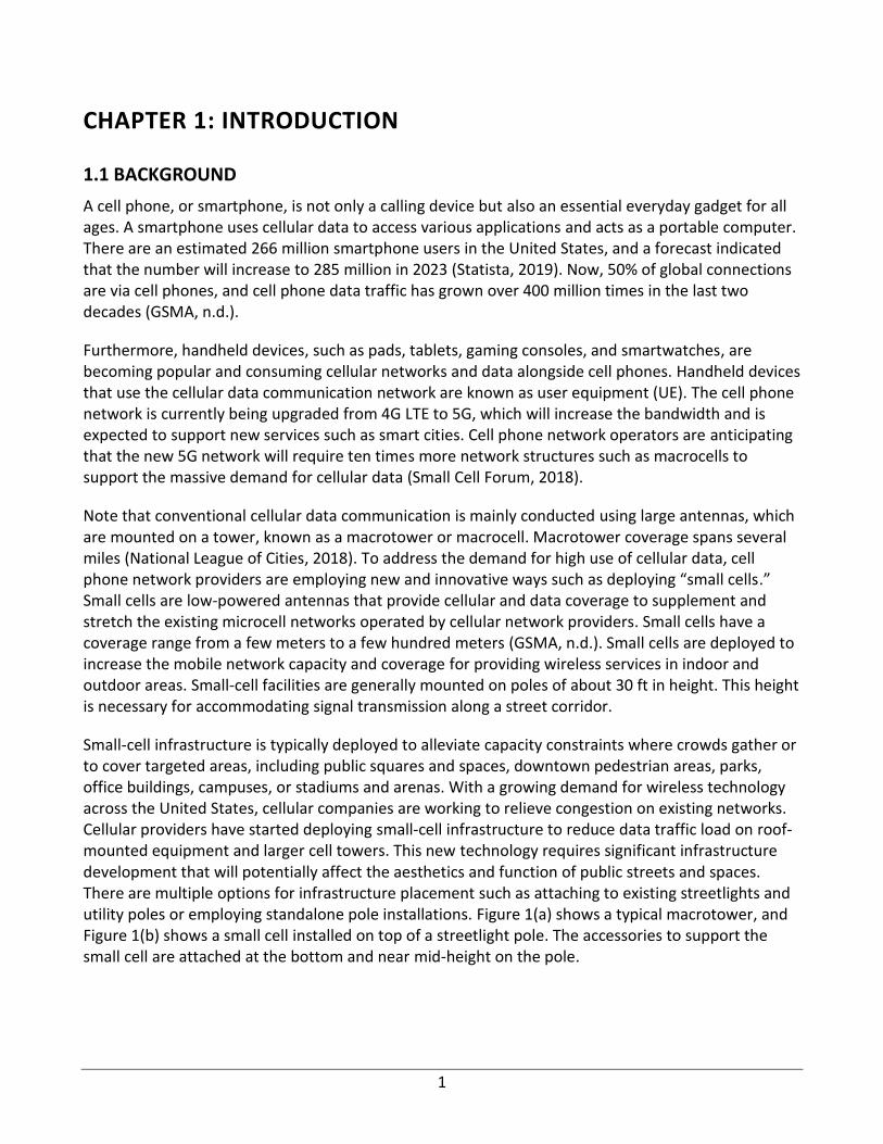
A cell phone, or smartphone, is not only a calling device but also an essential everyday gadget for all ages. A smartphone uses cellular data to access various applications and acts as a portable computer. There are an estimated 266 million smartphone users in the United States, and a forecast indicated that the number will increase to 285 million in 2023 (Statista, 2019). Now, 50% of global connections are via cell phones, and cell phone data traffic has grown over 400 million times in the last two decades (GSMA, n.d.).
Furthermore, handheld devices, such as pads, tablets, gaming consoles, and smartwatches, are becoming popular and consuming cellular networks and data alongside cell phones. Handheld devices that use the cellular data communication network are known as user equipment (UE). The cell phone network is currently being upgraded from 4G LTE to 5G, which will increase the bandwidth and is expected to support new services such as smart cities. Cell phone network operators are anticipating that the new 5G network will require ten times more network structures such as macrocells to support the massive demand for cellular data (Small Cell Forum, 2018).
Note that conventional cellular data communication is mainly conducted using large antennas, which are mounted on a tower, known as a macrotower or macrocell. Macrotower coverage spans several miles (National League of Cities, 2018). To address the demand for high use of cellular data, cell phone network providers are employing new and innovative ways such as deploying “small cells.” Small cells are low-powered antennas that provide cellular and data coverage to supplement and stretch the existing microcell networks operated by cellular network providers. Small cells have a coverage range from a few meters to a few hundred meters (GSMA, n.d.). Small cells are deployed to increase the mobile network capacity and coverage for providing wireless services in indoor and outdoor areas. Small-cell facilities are generally mounted on poles of about 30 ft in height. This height is necessary for accommodating signal transmission along a street corridor.
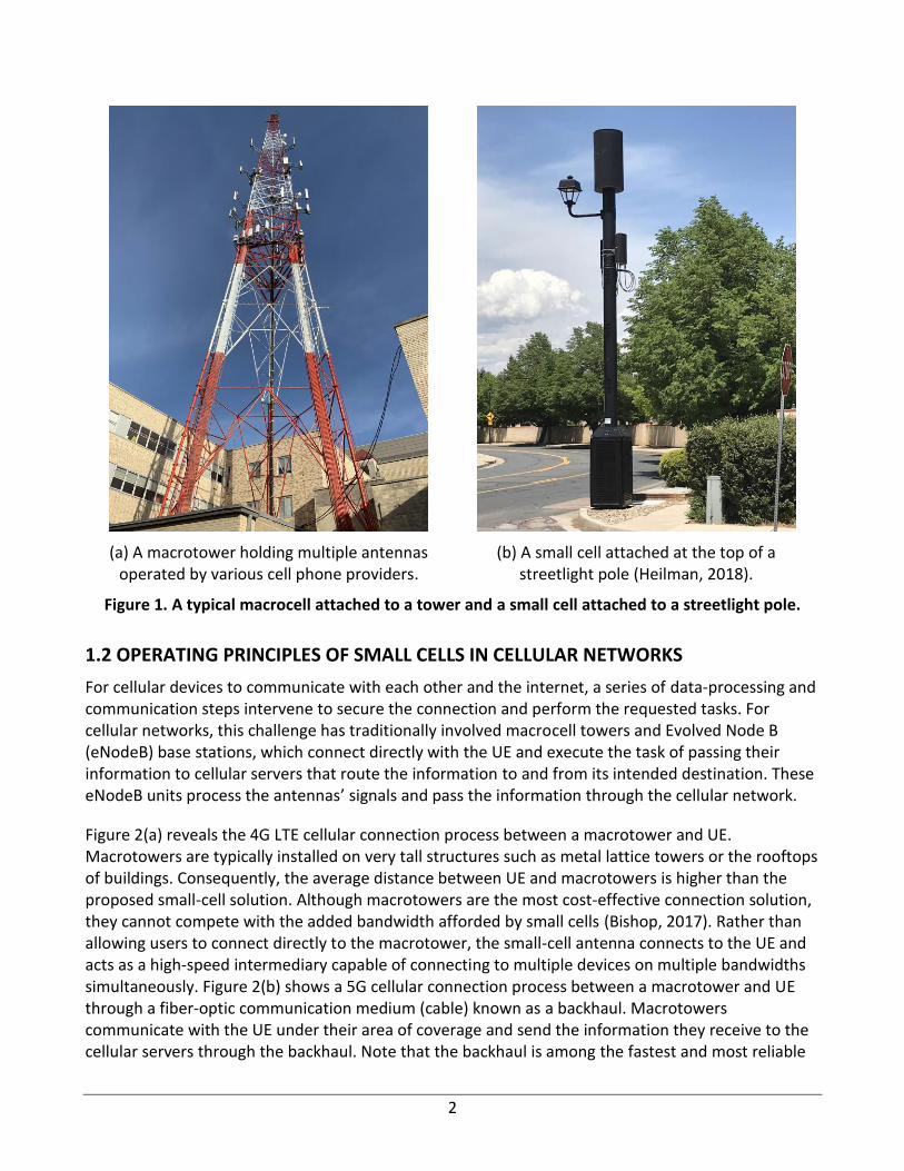
Small-cell infrastructure is typically deployed to alleviate capacity constraints where crowds gather or to cover targeted areas, including public squares and spaces, downtown pedestrian areas, parks, office buildings, campuses, or stadiums and arenas. With a growing demand for wireless technology across the United States, cellular companies are working to relieve congestion on existing networks. Cellular providers have started deploying small-cell infrastructure to reduce data traffic load on roof-mounted equipment and larger cell towers. This new technology requires significant infrastructure development that will potentially affect the aesthetics and function of public streets and spaces. There are multiple options for infrastructure placement such as attaching to existing streetlights and utility poles or employing standalone pole installations. Figure 1(a) shows a typical macrotower, and Figure 1(b) shows a small cell installed on top of a streetlight pole. The accessories to support the small cell are attached at the bottom and near mid-height on the pole.
2
(a) A macrotower holding multiple antennas operated by various cell phone providers.
(b) A small cell attached at the top of a streetlight pole (Heilman, 2018).
Figure 1. A typical macrocell attached to a tower and a small cell attached to a streetlight pole.
1.2 OPERATING PRINCIPLES OF SMALL CELLS IN CELLULAR NETWORKS
For cellular devices to communicate with each other and the internet, a series of data-processing and communication steps intervene to secure the connection and perform the requested tasks. For cellular networks, this challenge has traditionally involved macrocell towers and Evolved Node B (eNodeB) base stations, which connect directly with the UE and execute the task of passing their information to cellular servers that route the information to and from its intended destination. These eNodeB units process the antennas’ signals and pass the information through the cellular network.
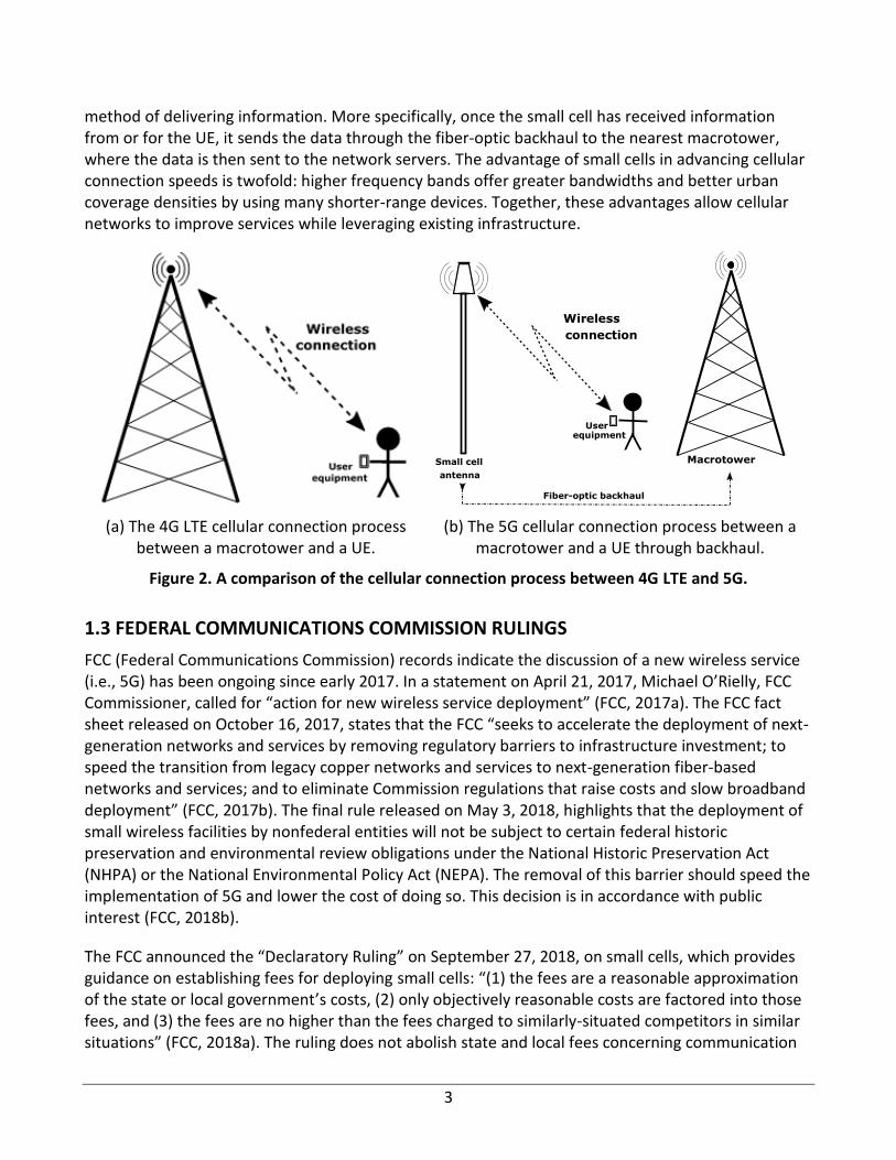
Figure 2(a) reveals the 4G LTE cellular connection process between a macrotower and UE. Macrotowers are typically installed on very tall structures such as metal lattice towers or the rooftops of buildings. Consequently, the average distance between UE and macrotowers is higher than the proposed small-cell solution. Although macrotowers are the most cost-effective connection solution, they cannot compete with the added bandwidth afforded by small cells (Bishop, 2017). Rather than allowing users to connect directly to the macrotower, the small-cell antenna connects to the UE and acts as a high-speed intermediary capable of connecting to multiple devices on multiple bandwidths simultaneously. Figure 2(b) shows a 5G cellular connection process between a macrotower and UE through a fiber-optic communication medium (cable) known as a backhaul. Macrotowers communicate with the UE under their area of coverage and send the information they receive to the cellular servers through the backhaul. Note that the backhaul is among the fastest and most reliable
3
method of delivering information. More specifically, once the small cell has received information from or for the UE, it sends the data through the fiber-optic backhaul to the nearest macrotower, where the data is then sent to the network servers. The advantage of small cells in advancing cellular connection speeds is twofold: higher frequency bands offer greater bandwidths and better urban coverage densities by using many shorter-range devices. Together, these advantages allow cellular networks to improve services while leveraging existing infrastructure.
(a) The 4G LTE cellular connection process between a macrotower and a UE.
(b) The 5G cellular connection process between a macrotower and a UE through backhaul.
Figure 2. A comparison of the cellular connection process between 4G LTE and 5G.
1.3 FEDERAL COMMUNICATIONS COMMISSION RULINGS
FCC (Federal Communications Commission) records indicate the discussion of a new wireless service (i.e., 5G) has been ongoing since early 2017. In a statement on April 21, 2017, Michael O’Rielly, FCC Commissioner, called for “action for new wireless service deployment” (FCC, 2017a). The FCC fact sheet released on October 16, 2017, states that the FCC “seeks to accelerate the deployment of next-generation networks and services by removing regulatory barriers to infrastructure investment; to speed the transition from legacy copper networks and services to next-generation fiber-based networks and services; and to eliminate Commission regulations that raise costs and slow broadband deployment” (FCC, 2017b). The final rule released on May 3, 2018, highlights that the deployment of small wireless facilities by nonfederal entities will not be subject to certain federal historic preservation and environmental review obligations under the National Historic Preservation Act (NHPA) or the National Environmental Policy Act (NEPA). The removal of this barrier should speed the implementation of 5G and lower the cost of doing so. This decision is in accordance with public interest (FCC, 2018b).
The FCC announced the “Declaratory Ruling” on September 27, 2018, on small cells, which provides guidance on establishing fees for deploying small cells: “(1) the fees are a reasonable approximation of the state or local government’s costs, (2) only objectively reasonable costs are factored into those fees, and (3) the fees are no higher than the fees charged to similarly-situated competitors in similar situations” (FCC, 2018a). The ruling does not abolish state and local fees concerning communication
Small cell antenna
Wireless
connection
Macrotower
User equipment
Fiber-optic backhaul
4
deployment, but it does limit these fees. As for regulations concerning aesthetic requirements, the ruling states they are permissible so long as these requirements “are reasonable in that they are technically feasible and reasonably directed to avoiding or remedying the intangible public harm of unsightly or out-of-character deployments” (FCC, 2018a). In addition, the ruling clarifies “shot clock” procedures for local review of wireless infrastructure deployment. Localities will have 60 days to review small-cell installations onto current structures and 90 days for installations onto new structures.
Jessica Rosenworcel, FCC member, encouraged cooperation between cities, states, and wireless facilities to streamline the process of updating the wireless network to 5G rather than relying on the federal ruling. The current situation is described as “extraordinary federal overreach” (FCC, 2018a). The ruling could potentially destroy current small-cell deployment processes that local governments already have. Rosenworcel suggested developing new codes for small cells and 5G deployment and making incentives for following these codes, recognizing the impact of high tariffs on the cost of upgrading to a 5G network and updating OTARD (Over-the-Air Reception Devices) rules to create a more competitive environment that would lower the cost of 5G deployment (FCC, 2018a).
Finally, Ajit Pai, FCC Chairman, supported the FCC ruling on small cells and the mandate for the shot clock and raised concerns that the cost of deploying wireless infrastructure will put those in rural areas at a disadvantage. The goal of the 5G network is the opposite. 5G should help to close the divide between rural and urban communities (FCC, 2018a). Brendan Carr, FCC member, expressed the worry of many smaller localities that big-city governments will delay the deployment of small wireless facilities through high fees and prolonged delays for approval. Carr provided four examples of people from small localities expressing the same worry. The race to 5G involves all people, which is why rural areas need equal access to 5G. Carr supported the allowance of “reasonable aesthetic reviews” (FCC, 2018a). Overall, Carr said it would speed up 5G deployment by saving billions of dollars in red tape (FCC, 2018a).
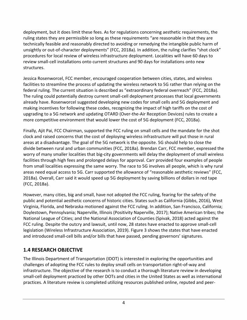
However, many cities, big and small, have not adopted the FCC ruling, fearing for the safety of the public and potential aesthetic concerns of historic cities. States such as California (Gibbs, 2016), West Virginia, Florida, and Nebraska motioned against the FCC ruling. In addition, San Francisco, California; Doylestown, Pennsylvania; Naperville, Illinois (Positivity Naperville, 2017); Native American tribes; the National League of Cities; and the National Association of Counties (Spivak, 2018) acted against the FCC ruling. Despite the outcry and lawsuit, until now, 28 states have enacted to approve small-cell legislation (Wireless Infrastructure Association, 2019). Figure 3 shows the states that have enacted and introduced small-cell bills and/or bills that have passed, pending governors’ signatures.
1.4 RESEARCH OBJECTIVE
The Illinois Department of Transportation (IDOT) is interested in exploring the opportunities and challenges of adopting the FCC rules to deploy small cells on transportation right-of-way and infrastructure. The objective of the research is to conduct a thorough literature review in developing small-cell deployment practiced by other DOTs and cities in the United States as well as international practices. A literature review is completed utilizing resources published online, reputed and peer-
5
reviewed journals, and conference articles. A survey was sent to all DOTs and counties in Illinois, asking for their experience with small-cell deployment.
Figure 3. State-enacted FCC rulings to deploy small cells as of December 2019.
1.5 RESEARCH APPROACH
The literature review is carried out by completing the following steps:
• FCC rulings and state legislations are reviewed to understand the current stage of deploying small cells in the United States. The court challenges against FCC rulings and associated community responses were recorded from news articles and newsletters of law firms associated with the FCC rulings.
• Small cells and their physical components, mechanical and electrical characteristics, operating principals, preferred small-cell hoisting structures, and the density of small cells in cities are studied from current written small-cell deployment standards or permit documents and online resources.
• A set of survey questions is developed and sent to state DOTs and Illinois counties to understand the state of the current practices on deploying small cells. The survey responses are summarized and further communicated with a few state and local agencies for collecting additional information.
6
• Small-cell safety in terms of maximum permissible exposure (MPE) is studied, current industry practices are evaluated, and public concerns are addressed. Journal publications are reviewed to address small-cell safety concerns.
• Small-cell permit documents are collected and summarized based on cellular providers’ and infrastructure owners’ responsibilities, construction, operation and maintenance details, bonding, and insurance requirements. Furthermore, state legislations are summarized to record small-cell permits and other fees, and state DOTs standards are reviewed to compare poles hosting small cells versus conventional street poles. Finally, a summary of nondestructive tests to check structural integrity and durability of existing poles is completed.
• Based on the current state of the practice, recommendations are provided to facilitate 5G cellular networks as well as ensure the safety of users and transparency among state DOTs, private companies, and taxpayers.
1.6 REPORT ORGANIZATION
This report is comprised of six chapters, including Chapter 1, which serves as the introduction. Chapter 2 details types of small cells and their components. Chapter 2 also highlights the physical, mechanical, and electrical characteristics of small cells, location to install or deploy small cells, and density of small cells in a city. Chapter 3 summarizes the survey responses received from the state of Illinois and its respective counties. Chapter 4 illustrates the safety concerns of small cells. Chapter 5 provides the contract details and state legislation summary, followed by the conclusion and recommendations in Chapter 6.
7
CHAPTER 2: SMALL CELLS
2.1 BACKGROUND
The transmission of data throughout an urban environment is vital to the success of modern cities. Previous generations of cellular infrastructure can no longer keep pace with the growing demand for communication (data transmission) bandwidth and throughput. The macrotowers that have been serving fourth-generation long-term evolution (4G LTE) networks cannot connect to the rapidly growing number of devices that each user is simultaneously utilizing. Previously, user equipment (UE) consisted of cell phones, and a few users owned multiple instances of their user equipment. The contemporary data landscape, however, has shifted, with demands for mobile devices, such as cell phones, smartwatches, laptops, and vehicles, for each user to be connected to the internet. Consequently, connection issues for city-dwellers have become apparent, and the frustration against poor connections has become palpable. To remedy such issues, 5G technology offers greater coverage and bandwidth to provide connections to the many devices utilizing the cellular network.
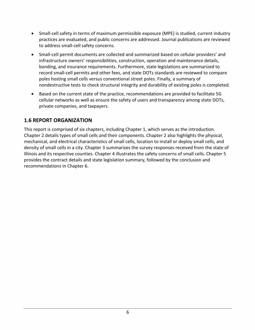
The next generation of cellular technology, 5G, represents a paradigm shift for cellular infrastructure. Illustrated in Figure 4, small cells act as a high-speed intermediary between a UE and macrotower. The UE connects directly to the nearest small-cell tower to send and receive data. This signal is processed and sent through a fiber-optic cable, known as a backhaul, to a macrotower. The macrotower then forwards the signal through the backhaul to the carrier’s switching office or cellular servers, which connect to the internet to fulfill the user’s request. These small cells offer higher bandwidth in part because of their service to a smaller audience and at a higher cellular frequency than existing systems. Existing macrotowers must serve a wide area of coverage and, therefore, bandwidth to a greater population. The frequency of a cellular signal is proportional to the bandwidth that is provided and is inversely proportional to the area of coverage.
Figure 4. A possible setup of small-cell technology in transportation infrastructure for 5G cellular networks.
8
Consequently, macrotowers provide 4G and 4G LTE coverage at lower frequencies, i.e., 2 GHz to 8 GHz, to a broader area (Haenggi, 2019). Small cells, on the other hand, provide 4G LTE as well as superior 5G coverage at higher frequencies of up to 28 GHz, according to the FCC (2019). This strategy necessitates a higher density of short-range antennas that require installation posts, structures standing approximately 25 ft tall or higher, to provide optimal coverage and to comply with existing electromagnetic frequency (EMF) exposure regulations.
The setup shown in Figure 4 takes the form of monopoles, which elevate the small-cell antenna and host the backhaul at the base of the structure or existing infrastructure, such as light poles or traffic lights. This infrastructure falls within the public domain, as it is installed within public walkways or intersections. Consequently, although small-cell equipment is owned and operated by the cellular carrier, the installation sites are under the control of the state and local departments of transportation (DOT). To install a new small cell and develop a 5G network, carriers must submit an application to the local DOT authority. Many DOTs have implemented regulations that determine if a small cell would disturb the aesthetics of the surrounding environment. Once these requirements have been satisfied, the carrier will proceed with the installation according to the terms agreed upon with the DOT.
Previous modes of cellular communication relied upon macrotower installations, which were fewer and farther between than the requirements of 5G small-cell poles. Consequently, the increased urban density required by small cells has inspired many cities to develop online databases where potential small-cell locations can be zoned and tracked in real time. These databases are typically publicly available, thus increasing the transparency of the 5G rollout with the general public. Despite this transparency, however, many municipalities have faced legal concerns from the public. These legal arguments claim that the installation of small-cell antennas represents a violation of the reasonable accommodations requested by electrically sensitive people under the Americans with Disabilities Act (ADA). Although no such legal argument has come to fruition, many DOTs have researched the potential legal and capital liabilities that such claims represent. Even though 5G technology poses several technological and policy challenges, the benefits afforded to 5G-capable cities are significant.
2.2 OVERVIEW OF SMALL-CELL TECHNOLOGY
2.2.1 Small-Cell Components
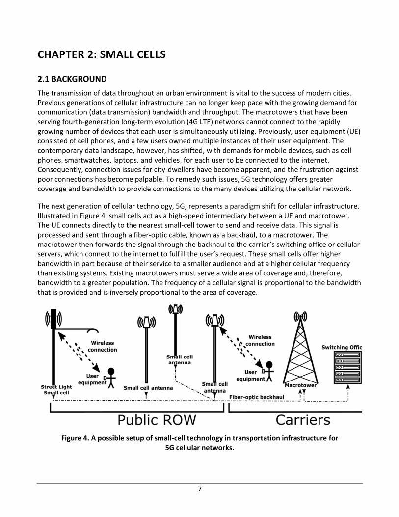
Figure 5 shows an antenna luminary assembly (ALA) that hosts a small-cell antenna inside the enclosed fiberglass dome. The antenna is powered by wires that are run through the tube. The tube is connected to a pole by the male end.
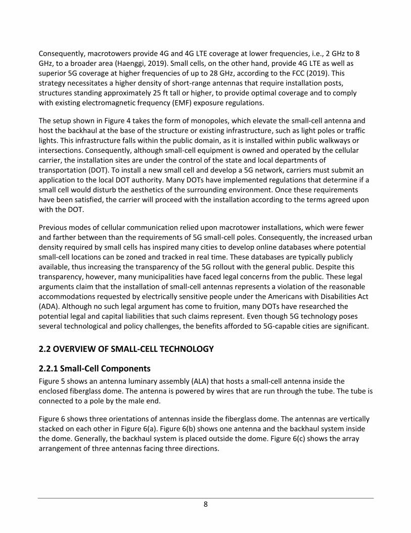
Figure 6 shows three orientations of antennas inside the fiberglass dome. The antennas are vertically stacked on each other in Figure 6(a). Figure 6(b) shows one antenna and the backhaul system inside the dome. Generally, the backhaul system is placed outside the dome. Figure 6(c) shows the array arrangement of three antennas facing three directions.
9
Figure 5. An antenna and cable connection system (Lasier & VanDonkelaar, 2017).
(a) Antenna arrangement 1 (b) Antenna arrangement 2 (c) Antenna arrangement 3
Figure 6. Antenna arrangements inside ALA (Lasier & VanDonkelaar, 2017).
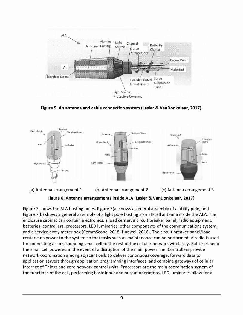
Figure 7 shows the ALA hosting poles. Figure 7(a) shows a general assembly of a utility pole, and Figure 7(b) shows a general assembly of a light pole hosting a small-cell antenna inside the ALA. The enclosure cabinet can contain electronics, a load center, a circuit breaker panel, radio equipment, batteries, controllers, processors, LED luminaries, other components of the communications system, and a service entry meter box (CommScope, 2018; Huawei, 2016). The circuit breaker panel/load center cuts power to the system so that tasks such as maintenance can be performed. A radio is used for connecting a corresponding small cell to the rest of the cellular network wirelessly. Batteries keep the small cell powered in the event of a disruption of the main power line. Controllers provide network coordination among adjacent cells to deliver continuous coverage, forward data to application servers through application programming interfaces, and combine gateways of cellular Internet of Things and core network control units. Processors are the main coordination system of the functions of the cell, performing basic input and output operations. LED luminaries allow for a
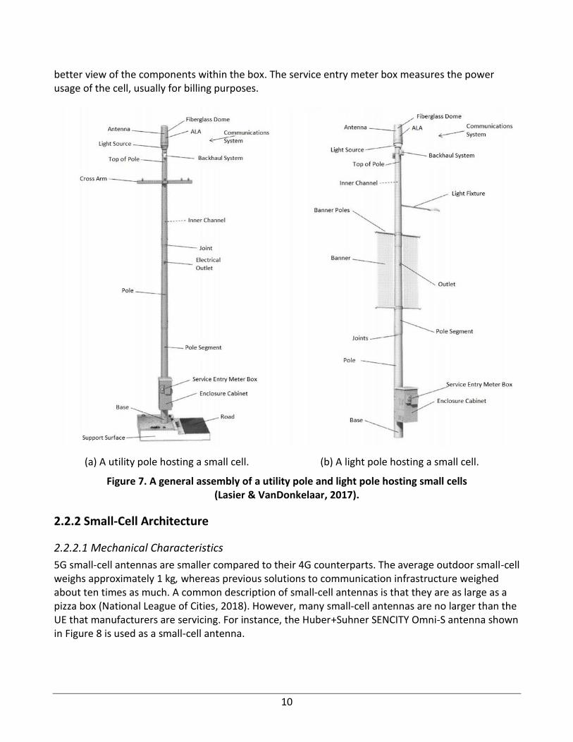
10
better view of the components within the box. The service entry meter box measures the power usage of the cell, usually for billing purposes.
(a) A utility pole hosting a small cell. (b) A light pole hosting a small cell.
Figure 7. A general assembly of a utility pole and light pole hosting small cells (Lasier & VanDonkelaar, 2017).
2.2.2 Small-Cell Architecture
2.2.2.1 Mechanical Characteristics
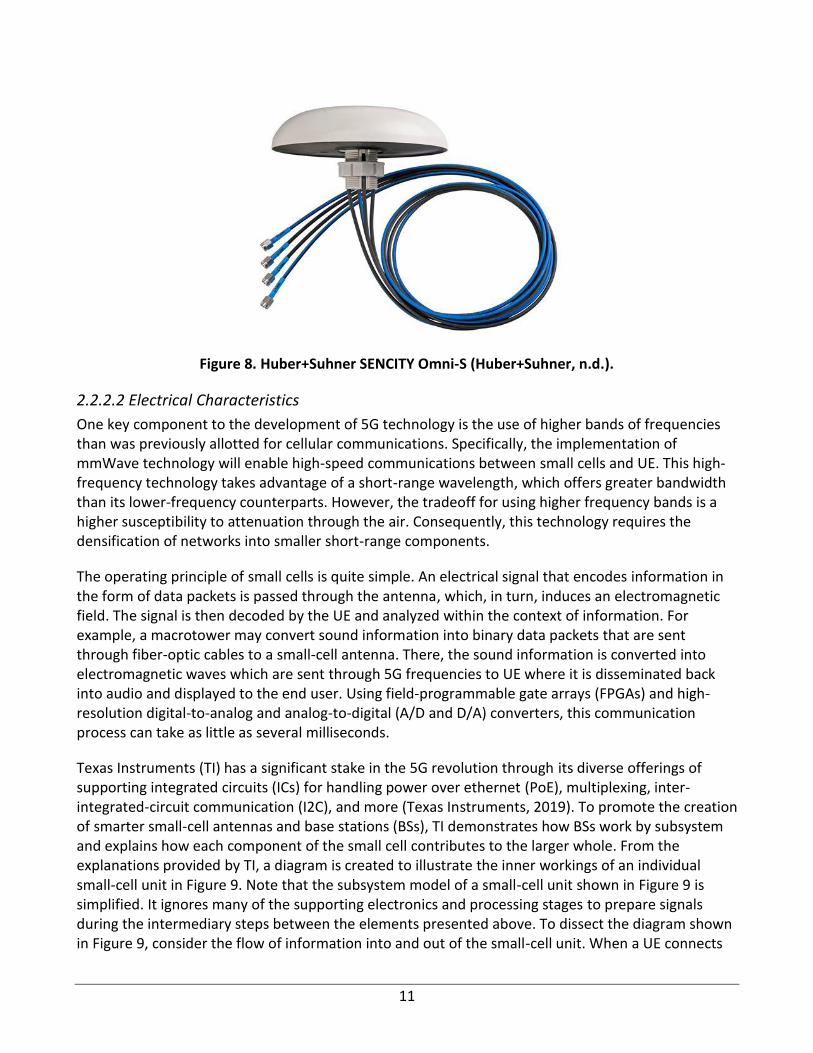
5G small-cell antennas are smaller compared to their 4G counterparts. The average outdoor small-cell weighs approximately 1 kg, whereas previous solutions to communication infrastructure weighed about ten times as much. A common description of small-cell antennas is that they are as large as a pizza box (National League of Cities, 2018). However, many small-cell antennas are no larger than the UE that manufacturers are servicing. For instance, the Huber+Suhner SENCITY Omni-S antenna shown in Figure 8 is used as a small-cell antenna.
11
Figure 8. Huber+Suhner SENCITY Omni-S (Huber+Suhner, n.d.).
2.2.2.2 Electrical Characteristics
One key component to the development of 5G technology is the use of higher bands of frequencies than was previously allotted for cellular communications. Specifically, the implementation of mmWave technology will enable high-speed communications between small cells and UE. This high-frequency technology takes advantage of a short-range wavelength, which offers greater bandwidth than its lower-frequency counterparts. However, the tradeoff for using higher frequency bands is a higher susceptibility to attenuation through the air. Consequently, this technology requires the densification of networks into smaller short-range components.
The operating principle of small cells is quite simple. An electrical signal that encodes information in the form of data packets is passed through the antenna, which, in turn, induces an electromagnetic field. The signal is then decoded by the UE and analyzed within the context of information. For example, a macrotower may convert sound information into binary data packets that are sent through fiber-optic cables to a small-cell antenna. There, the sound information is converted into electromagnetic waves which are sent through 5G frequencies to UE where it is disseminated back into audio and displayed to the end user. Using field-programmable gate arrays (FPGAs) and high-resolution digital-to-analog and analog-to-digital (A/D and D/A) converters, this communication process can take as little as several milliseconds.
Texas Instruments (TI) has a significant stake in the 5G revolution through its diverse offerings of supporting integrated circuits (ICs) for handling power over ethernet (PoE), multiplexing, inter-integrated-circuit communication (I2C), and more (Texas Instruments, 2019). To promote the creation of smarter small-cell antennas and base stations (BSs), TI demonstrates how BSs work by subsystem and explains how each component of the small cell contributes to the larger whole. From the explanations provided by TI, a diagram is created to illustrate the inner workings of an individual small-cell unit in Figure 9. Note that the subsystem model of a small-cell unit shown in Figure 9 is simplified. It ignores many of the supporting electronics and processing stages to prepare signals during the intermediary steps between the elements presented above. To dissect the diagram shown in Figure 9, consider the flow of information into and out of the small-cell unit. When a UE connects
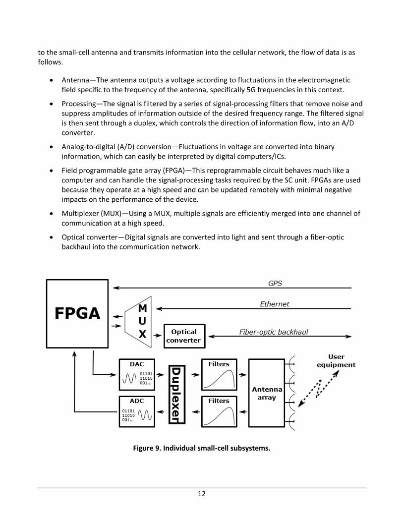
12
to the small-cell antenna and transmits information into the cellular network, the flow of data is as follows.
• Antenna—The antenna outputs a voltage according to fluctuations in the electromagnetic field specific to the frequency of the antenna, specifically 5G frequencies in this context.
• Processing—The signal is filtered by a series of signal-processing filters that remove noise and suppress amplitudes of information outside of the desired frequency range. The filtered signal is then sent through a duplex, which controls the direction of information flow, into an A/D converter.
• Analog-to-digital (A/D) conversion—Fluctuations in voltage are converted into binary information, which can easily be interpreted by digital computers/ICs.
• Field programmable gate array (FPGA)—This reprogrammable circuit behaves much like a computer and can handle the signal-processing tasks required by the SC unit. FPGAs are used because they operate at a high speed and can be updated remotely with minimal negative impacts on the performance of the device.
• Multiplexer (MUX)—Using a MUX, multiple signals are efficiently merged into one channel of communication at a high speed.
• Optical converter—Digital signals are converted into light and sent through a fiber-optic backhaul into the communication network.
Figure 9. Individual small-cell subsystems.
13
Although these stages seem complex, the process of communicating with a small-cell unit is complete within a few milliseconds. One of the great advantages afforded to small cells is their ability to communicate with many instances of UE simultaneously. For instance, a single small-cell unit will often contain multiple antennas that operate at different 5G and 4G LTE frequencies. If one frequency range is saturated with competing devices, then the UE can simply connect to another antenna operating at a less busy frequency range. Additionally, their high speed and consolidated design enable a single small cell to cut the intermediate-processing needs to a minimum, reducing the number of reading/writing times per communication instance.
Receiving information from the network is as simple as reversing the information flow. The first data optical converter reads optical data into binary, and the MUX splits the signal into their respective signal paths. Each signal is then processed by the FPGA before being converted from digital to analog (DAC) and sent through a series of filters before being broadcast through the small-cell antenna. This process similarly occurs in a matter of a few milliseconds.
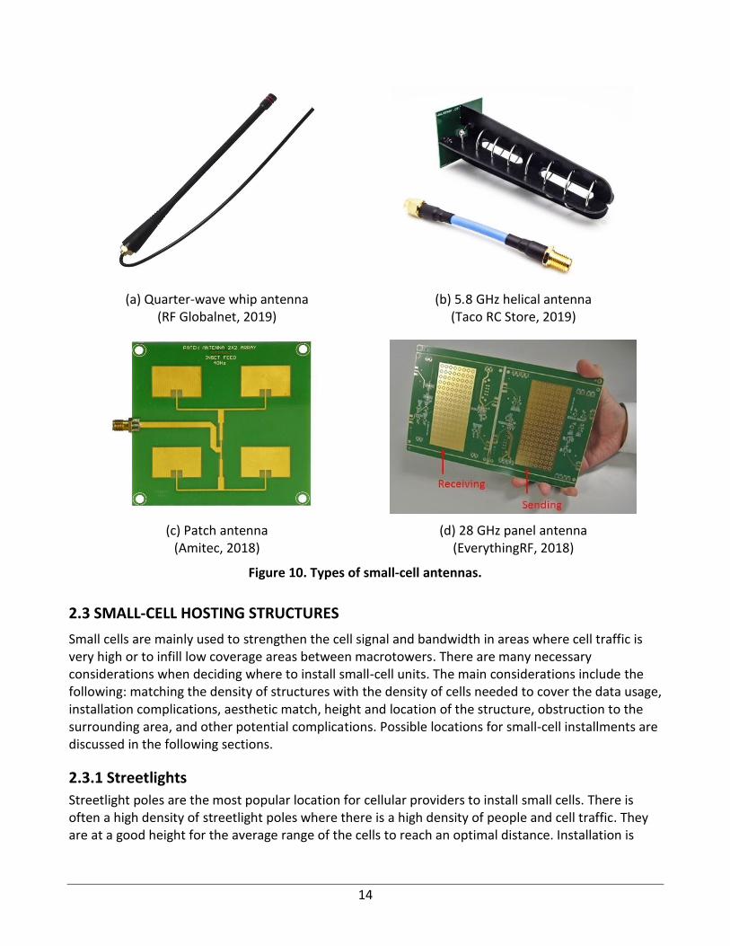
2.2.2.3 Antenna Types
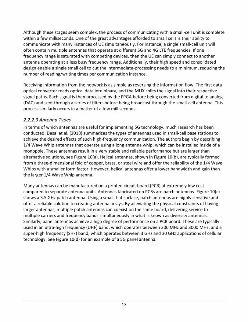
In terms of which antennas are useful for implementing 5G technology, much research has been conducted. Desai et al. (2018) summarizes the types of antennas used in small-cell base stations to achieve the desired effects of such high-frequency communication. The authors begin by describing 1/4 Wave Whip antennas that operate using a long antenna whip, which can be installed inside of a monopole. These antennas result in a very stable and reliable performance but are larger than alternative solutions, see Figure 10(a). Helical antennas, shown in Figure 10(b), are typically formed from a three-dimensional fold of copper, brass, or steel wire and offer the reliability of the 1/4 Wave Whips with a smaller form factor. However, helical antennas offer a lower bandwidth and gain than the larger 1/4 Wave Whip antenna.
Many antennas can be manufactured on a printed circuit board (PCB) at extremely low cost compared to separate antenna units. Antennas fabricated on PCBs are patch antennas. Figure 10(c) shows a 3.5 GHz patch antenna. Using a small, flat surface, patch antennas are highly sensitive and offer a reliable solution to creating antenna arrays. By alleviating the physical constraints of having larger antennas, multiple patch antennas can coexist on the same board, delivering service to multiple carriers and frequency bands simultaneously in what is known as diversity antennas. Similarly, panel antennas achieve a high degree of performance on a PCB board. These are typically used in an ultra-high frequency (UHF) band, which operates between 300 MHz and 3000 MHz, and a super-high frequency (SHF) band, which operates between 3 GHz and 30 GHz applications of cellular technology. See Figure 10(d) for an example of a 5G panel antenna.
14
(a) Quarter-wave whip antenna (RF Globalnet, 2019)
(b) 5.8 GHz helical antenna (Taco RC Store, 2019)
(c) Patch antenna (Amitec, 2018)
(d) 28 GHz panel antenna (EverythingRF, 2018)
Figure 10. Types of small-cell antennas.
2.3 SMALL-CELL HOSTING STRUCTURES
Small cells are mainly used to strengthen the cell signal and bandwidth in areas where cell traffic is very high or to infill low coverage areas between macrotowers. There are many necessary considerations when deciding where to install small-cell units. The main considerations include the following: matching the density of structures with the density of cells needed to cover the data usage, installation complications, aesthetic match, height and location of the structure, obstruction to the surrounding area, and other potential complications. Possible locations for small-cell installments are discussed in the following sections.
2.3.1 Streetlights
Streetlight poles are the most popular location for cellular providers to install small cells. There is often a high density of streetlight poles where there is a high density of people and cell traffic. They are at a good height for the average range of the cells to reach an optimal distance. Installation is
15
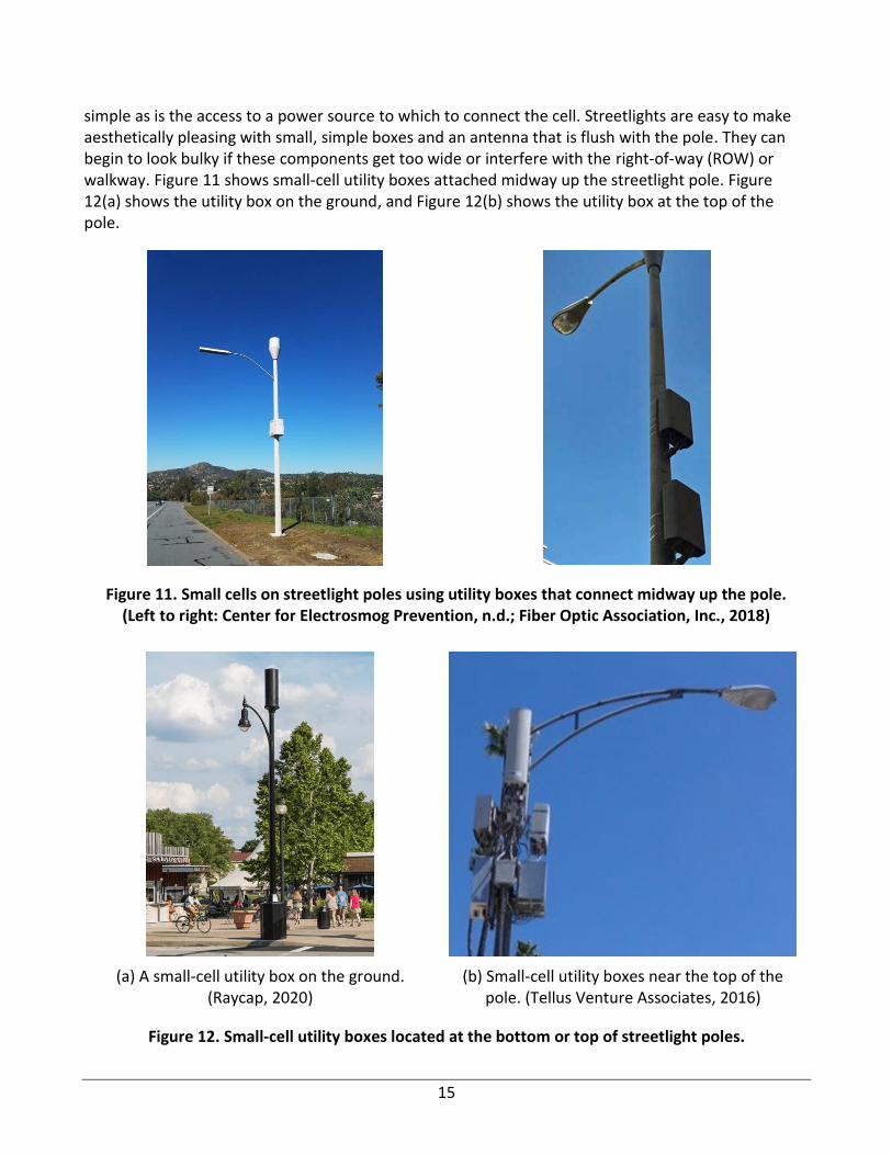
simple as is the access to a power source to which to connect the cell. Streetlights are easy to make aesthetically pleasing with small, simple boxes and an antenna that is flush with the pole. They can begin to look bulky if these components get too wide or interfere with the right-of-way (ROW) or walkway. Figure 11 shows small-cell utility boxes attached midway up the streetlight pole. Figure 12(a) shows the utility box on the ground, and Figure 12(b) shows the utility box at the top of the pole.
Figure 11. Small cells on streetlight poles using utility boxes that connect midway up the pole. (Left to right: Center for Electrosmog Prevention, n.d.; Fiber Optic Association, Inc., 2018)
(a) A small-cell utility box on the ground. (Raycap, 2020)
(b) Small-cell utility boxes near the top of the pole. (Tellus Venture Associates, 2016)
Figure 12. Small-cell utility boxes located at the bottom or top of streetlight poles.
16
Metal boxes allow for the option of running conduits in the interior of the pole. Also, the small cell’s metal equipment better matches aesthetically with a metal pole than a wooden one. Streetlight poles offer great locations for directional cells because of their location on streets and walkways and are generally surrounded by buildings. However, the buildings can block their signals from entering far into the interior of the building. The 5G signal is blocked by common window tints, so a repeater may have to be installed on the inside of the glass to allow the signal to enter the building.
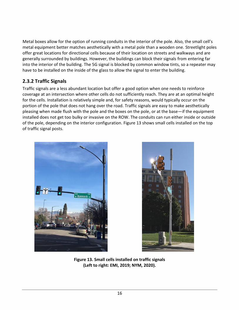
2.3.2 Traffic Signals
Traffic signals are a less abundant location but offer a good option when one needs to reinforce coverage at an intersection where other cells do not sufficiently reach. They are at an optimal height for the cells. Installation is relatively simple and, for safety reasons, would typically occur on the portion of the pole that does not hang over the road. Traffic signals are easy to make aesthetically pleasing when made flush with the pole and the boxes on the pole, or at the base—if the equipment installed does not get too bulky or invasive on the ROW. The conduits can run either inside or outside of the pole, depending on the interior configuration. Figure 13 shows small cells installed on the top of traffic signal posts.
Figure 13. Small cells installed on traffic signals (Left to right: EMI, 2019; NYM, 2020).
17
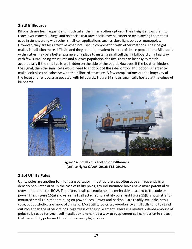
2.3.3 Billboards
Billboards are less frequent and much taller than many other options. Their height allows them to reach over many buildings and obstacles that lower cells may be hindered by, allowing them to fill gaps in signals along with other small-cell applications such as close light poles or monopoles. However, they are less effective when not used in combination with other methods. Their height makes installation more difficult, and they are not prevalent in areas of dense populations. Billboards within cities may be a better example of a place to install a small cell than a billboard on a highway with few surrounding structures and a lower population density. They can be easy to match aesthetically if the small cells are hidden on the side of the board. However, if the location hinders the signal, then the small cells would need to stick out of the sides or top. This option is harder to make look nice and cohesive with the billboard structure. A few complications are the longevity of the lease and rent costs associated with billboards. Figure 14 shows small cells hosted at the edges of billboards.
Figure 14. Small cells hosted on billboards (Left to right: OAAA, 2016; TTS, 2019).
2.3.4 Utility Poles
Utility poles are another form of transportation infrastructure that often appear frequently in a densely populated area. In the case of utility poles, ground-mounted boxes have more potential to crowd or impede the ROW. Therefore, small-cell equipment is preferably attached to the pole or power lines. Figure 15(a) shows a small cell attached to a utility pole, and Figure 15(b) shows strand-mounted small cells that are hung on power lines. Power and backhaul are readily available in this case, but aesthetics are more of an issue. Most utility poles are wooden, so small cells tend to stand out more than the other options, regardless of their placement. There is a relatively dense amount of poles to be used for small-cell installation and can be a way to supplement cell connection in places that have utility poles and lines but not many light poles.

18
(a) A small cell and utility boxes are installed at the mid-location of a utility pole (Daily
Herald, 2018).
(b) Small cells and utility boxes are hung from power lines (Wade4Wireless, 2015).
Figure 15. Small cells installed on wooden utility poles.
2.3.5 Bus Shelters
Bus shelters offer many ways to match small cells aesthetically or hide them within a shelter. Some examples include on the sides or top of advertisement boards, within a box on top of the shelter, within signs depicting the stops that the buses make, etc. Figure 16 shows small cells inside an advertisement board at a bus shelter. They are abundant in cities and areas of higher population density and are also in a place where people tend to linger, causing many people to connect to that cell for a fair stretch of time. These locations are a bit shorter than other options, which could potentially hinder cell signal ranges. This option would be best used in combination with other applications, such as light poles and monopoles.
Figure 16. Small cells installed inside an advertising board at a bus shelter (ThinkSmallCell, 2017).
19
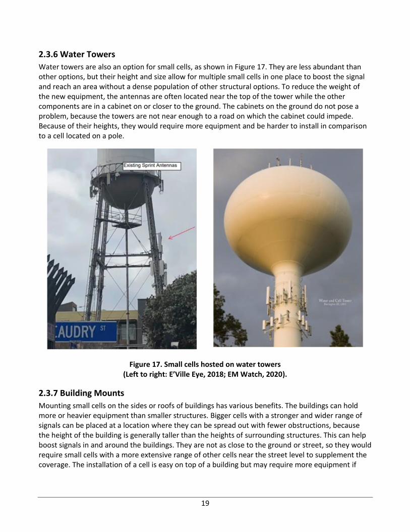
2.3.6 Water Towers
Water towers are also an option for small cells, as shown in Figure 17. They are less abundant than other options, but their height and size allow for multiple small cells in one place to boost the signal and reach an area without a dense population of other structural options. To reduce the weight of the new equipment, the antennas are often located near the top of the tower while the other components are in a cabinet on or closer to the ground. The cabinets on the ground do not pose a problem, because the towers are not near enough to a road on which the cabinet could impede. Because of their heights, they would require more equipment and be harder to install in comparison to a cell located on a pole.
Figure 17. Small cells hosted on water towers (Left to right: E’Ville Eye, 2018; EM Watch, 2020).
2.3.7 Building Mounts
Mounting small cells on the sides or roofs of buildings has various benefits. The buildings can hold more or heavier equipment than smaller structures. Bigger cells with a stronger and wider range of signals can be placed at a location where they can be spread out with fewer obstructions, because the height of the building is generally taller than the heights of surrounding structures. This can help boost signals in and around the buildings. They are not as close to the ground or street, so they would require small cells with a more extensive range of other cells near the street level to supplement the coverage. The installation of a cell is easy on top of a building but may require more equipment if
20
mounted on the side. Aesthetically speaking, a side-mounted cell would protrude more than one mounted on a roof.
2.4 SMALL-CELL LOCATION AND DENSITY
The location of small-cell installations is determined using a combination of technical and legal standards. For instance, there is a technical component to the placements of small cells with respect to their performance in an ultra-dense network (UDN) as well as their coverage with respect to the surrounding urban environment. Additionally, there are safety concerns generated through public input as well as through FCC regulations governing public and professional electromagnetic frequency (EMF) exposure. Consequently, the manner in which small-cell sites are determined is a multivariate problem. Given that, safety concerns of small cells and their contemporary regulations in charge of limiting EMF exposure are discussed in Chapter 4.
2.4.1 Individual Small-Cell Sites
It is important to distinguish the contexts for determining small-cell sites. Individual locations are subject to MPE reviews, aesthetic concerns, and structural requirements. This section covers how these constraints motivate DOTs to favor certain installation types over others.
2.4.1.1 MPE & Structural Constraints
As a logical consequence of MPE limitations, small-cell sites are required to distance themselves from public walkways without compromising cellular coverage. These distances vary depending on the context of the installation as well as the frequency bands and effective radiated power (ERP) of the antenna in question. Generally, municipalities prefer to put approximately 20 ft spacing between the small cell and public places of travel, such as sidewalks. To accommodate this request, many cities have utilized monopoles and rooftops as well as taking advantage of existing infrastructure such as light poles and power lines.
Requests to install small-cell antennas on poles or street lighting systems take longer to process because these sites often have specific designs and particulars that affect MPE reports and DOT oversight. These requests can slow a city’s small-cell ambitions. To combat this delay, Seattle proposed a standard that allows carriers to install small-cell antenna locations on any wooden distribution pole beneath the distribution conductor (City of Seattle, 2018). This deal allows requests for this type of small-cell site to be approved quicker than through traditional channels and will expedite citywide small-cell deployment. However, this would only be quicker when the pole is owned by a local government agency. Private utility companies are not held to the FCC shot clock and permitting requirements. The City still requires appropriate MPE reports to evaluate the public safety of installations of this type. However, MPE reports can evaluate general installation scenarios that cover most requests, which can be automatically approved provided that several general design constraints detailed in Table 1 are obeyed.
21
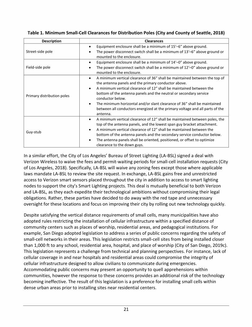
Table 1. Minimum Small-Cell Clearances for Distribution Poles (City and County of Seattle, 2018)
Description Clearances
Street-side pole • Equipment enclosure shall be a minimum of 15′–6″ above ground.
• The power disconnect switch shall be a minimum of 13′–6″ above ground or mounted to the enclosure.
Field-side pole • Equipment enclosure shall be a minimum of 14′–0″ above ground.
• The power disconnect switch shall be a minimum of 12′–0″ above ground or mounted to the enclosure.
Primary distribution poles
• A minimum vertical clearance of 36″ shall be maintained between the top of the antenna panels and the primary conductor above.
• A minimum vertical clearance of 12″ shall be maintained between the bottom of the antenna panels and the neutral or secondary service conductor below.
• The minimum horizontal and/or slant clearance of 36″ shall be maintained between all conductors energized at the primary voltage and all parts of the antenna.
Guy-stub
• A minimum vertical clearance of 12″ shall be maintained between poles, the top of the antenna panels, and the lowest span guy bracket attachment.
• A minimum vertical clearance of 12″ shall be maintained between the bottom of the antenna panels and the secondary service conductor below.
• The antenna panels shall be oriented, positioned, or offset to optimize clearance to the down guys.
In a similar effort, the City of Los Angeles’ Bureau of Street Lighting (LA-BSL) signed a deal with Verizon Wireless to waive the fees and permit-waiting periods for small-cell installation requests (City of Los Angeles, 2018). Specifically, LA-BSL will waive any zoning fees except those where applicable laws mandate LA-BSL to review the site request. In exchange, LA-BSL gains free and unrestricted access to Verizon smart sensors placed throughout the city in addition to access to smart lighting nodes to support the city’s Smart Lighting projects. This deal is mutually beneficial to both Verizon and LA-BSL, as they each expedite their technological ambitions without compromising their legal obligations. Rather, these parties have decided to do away with the red tape and unnecessary oversight for these locations and focus on improving their city by rolling out new technology quickly.
Despite satisfying the vertical distance requirements of small cells, many municipalities have also adopted rules restricting the installation of cellular infrastructure within a specified distance of community centers such as places of worship, residential areas, and pedagogical institutions. For example, San Diego adopted legislation to address a series of public concerns regarding the safety of small-cell networks in their areas. This legislation restricts small-cell sites from being installed closer than 1,000 ft to any school, residential area, hospital, and place of worship (City of San Diego, 2019c). This legislation represents a challenge from technical and planning perspectives. For instance, lack of cellular coverage in and near hospitals and residential areas could compromise the integrity of cellular infrastructure designed to allow civilians to communicate during emergencies. Accommodating public concerns may present an opportunity to quell apprehensions within communities, however the response to these concerns provides an additional risk of the technology becoming ineffective. The result of this legislation is a preference for installing small cells within dense urban areas prior to installing sites near residential centers.
22
2.4.1.2 Aesthetic Concerns
Setting aside the technical and safety challenges facing small-cell distribution, many cities are concerned that the small-cell sites will compromise the aesthetics of the city. Consequently, many municipalities have drafted guidelines for small-cell rollout. They included preferred designs to standardize the look of new structures and to govern the use of existing infrastructure such as street lights, which are now being repurposed to include the role of hosting antennas in addition to the luminaire.
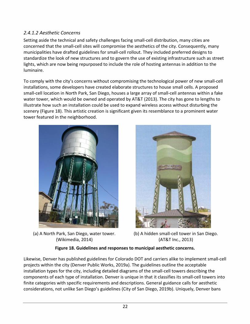
To comply with the city’s concerns without compromising the technological power of new small-cell installations, some developers have created elaborate structures to house small cells. A proposed small-cell location in North Park, San Diego, houses a large array of small-cell antennas within a fake water tower, which would be owned and operated by AT&T (2013). The city has gone to lengths to illustrate how such an installation could be used to expand wireless access without disturbing the scenery (Figure 18). This artistic creation is significant given its resemblance to a prominent water tower featured in the neighborhood.
(a) A North Park, San Diego, water tower. (Wikimedia, 2014)
(b) A hidden small-cell tower in San Diego. (AT&T Inc., 2013)
Figure 18. Guidelines and responses to municipal aesthetic concerns.
Likewise, Denver has published guidelines for Colorado DOT and carriers alike to implement small-cell projects within the city (Denver Public Works, 2019a). The guidelines outline the acceptable installation types for the city, including detailed diagrams of the small-cell towers describing the components of each type of installation. Denver is unique in that it classifies its small-cell towers into finite categories with specific requirements and descriptions. General guidance calls for aesthetic considerations, not unlike San Diego’s guidelines (City of San Diego, 2019b). Uniquely, Denver bans

23
small-cell tower locations from being visible within intersections’ line-of-sight triangles, as shown in Figure 19. This is significant because such locations are prime real estate for maximizing intersection small-cell coverage. Many municipal aesthetic regulations threaten the technological success of their 5G solutions. This balance between technology and aesthetics has a significant influence on the approval or disapproval of an installation request.
Figure 19. Denver street corner limitations (Denver Public Works, 2019a).
Alternatively, many below-ground solutions for 5G base stations have risen to prominence. Jamaly et al. (2017) proposed a unique small-cell antenna (SCA) design that involved the use of manhole covers. Therein, the design limits intercell interference and increases the area spectral efficiency (ASE). The design was then deployed and tested in Switzerland, and the results of the test prove the viability of the product. This design is significant because of its use of existing infrastructure. Many SCA manufacturers focus on limiting the impact of their deployment and an in-ground installation might be the best option to reduce the impact. However, many SCAs rely on their height to pass FCC MPE regulations, and existing RFE reports suggest that such an installation will not pass existing regulations in the United States (Crown Castle, 2019). Figure 20 is a photo of one such manhole small cell in comparison to a manhole cover.
Figure 20. In-ground small-cell antenna (Jamaly et al., 2017).
24
2.5 SMALL-CELL NETWORK
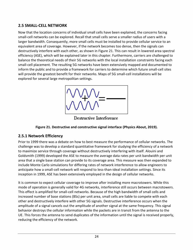
Now that the location concerns of individual small cells have been explained, the concerns facing small-cell networks can be explored. Recall that small cells serve a smaller radius of users with a larger bandwidth. Consequently, more small cells must be installed to provide cellular service to an equivalent area of coverage. However, if the network becomes too dense, then the signals can destructively interfere with each other, as shown in Figure 21. This can result in lowered area spectral efficiency (ASE), which will be explained later in this chapter. Furthermore, carriers are challenged to balance the theoretical needs of their 5G networks with the local installation constraints facing each small-cell placement. The resulting 5G networks have been extensively mapped and documented to inform the public and to provide a framework for carriers to determine which future small-cell sites will provide the greatest benefit for their networks. Maps of 5G small-cell installations will be explored for several large metropolitan settings.
Figure 21. Destructive and constructive signal interface (Physics About, 2019).
2.5.1 Network Efficiency
Prior to 1999 there was a debate on how to best measure the performance of cellular networks. The challenge was to develop a standard quantitative framework for studying the efficiency of a network to maximize service through coverage without destructively interfering with itself. Alouini and Goldsmith (1999) developed the ASE to measure the average data rates per unit bandwidth per unit area that a single base station can provide to its coverage area. This measure was then expanded to include Monte Carlo simulations for differing rates of network interference to allow engineers to anticipate how a small-cell network will respond to less-than-ideal installation settings. Since its inception in 1999, ASE has been extensively employed in the design of cellular networks.
It is common to expect cellular coverage to improve after installing more macrotowers. While this mode of operation is generally valid for 4G networks, interference still occurs between macrotowers. This effect is amplified for small-cell networks. Because of the high bandwidth of small cells and increased number of base stations (BSs) per unit area, small cells are liable to compete with each other and destructively interfere with other 5G signals. Destructive interference occurs when the amplitude of a signal cancels out the amplitude of another signal at the same frequency. This signal behavior destroys the cellular information while the packets are in transit from the antenna to the UE. This forces the antenna to send duplicates of the information until the signal is received properly, reducing the efficiency of the network.
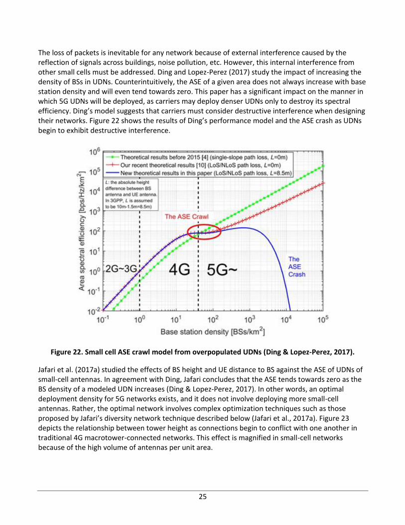
25
The loss of packets is inevitable for any network because of external interference caused by the reflection of signals across buildings, noise pollution, etc. However, this internal interference from other small cells must be addressed. Ding and Lopez-Perez (2017) study the impact of increasing the density of BSs in UDNs. Counterintuitively, the ASE of a given area does not always increase with base station density and will even tend towards zero. This paper has a significant impact on the manner in which 5G UDNs will be deployed, as carriers may deploy denser UDNs only to destroy its spectral efficiency. Ding’s model suggests that carriers must consider destructive interference when designing their networks. Figure 22 shows the results of Ding’s performance model and the ASE crash as UDNs begin to exhibit destructive interference.
Figure 22. Small cell ASE crawl model from overpopulated UDNs (Ding & Lopez-Perez, 2017).
Jafari et al. (2017a) studied the effects of BS height and UE distance to BS against the ASE of UDNs of small-cell antennas. In agreement with Ding, Jafari concludes that the ASE tends towards zero as the BS density of a modeled UDN increases (Ding & Lopez-Perez, 2017). In other words, an optimal deployment density for 5G networks exists, and it does not involve deploying more small-cell antennas. Rather, the optimal network involves complex optimization techniques such as those proposed by Jafari’s diversity network technique described below (Jafari et al., 2017a). Figure 23 depicts the relationship between tower height as connections begin to conflict with one another in traditional 4G macrotower-connected networks. This effect is magnified in small-cell networks because of the high volume of antennas per unit area.
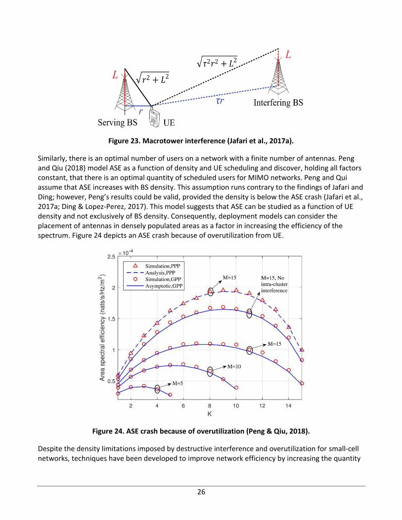
26
Figure 23. Macrotower interference (Jafari et al., 2017a).
Similarly, there is an optimal number of users on a network with a finite number of antennas. Peng and Qiu (2018) model ASE as a function of density and UE scheduling and discover, holding all factors constant, that there is an optimal quantity of scheduled users for MIMO networks. Peng and Qui assume that ASE increases with BS density. This assumption runs contrary to the findings of Jafari and Ding; however, Peng’s results could be valid, provided the density is below the ASE crash (Jafari et al., 2017a; Ding & Lopez-Perez, 2017). This model suggests that ASE can be studied as a function of UE density and not exclusively of BS density. Consequently, deployment models can consider the placement of antennas in densely populated areas as a factor in increasing the efficiency of the spectrum. Figure 24 depicts an ASE crash because of overutilization from UE.
Figure 24. ASE crash because of overutilization (Peng & Qiu, 2018).
Despite the density limitations imposed by destructive interference and overutilization for small-cell networks, techniques have been developed to improve network efficiency by increasing the quantity
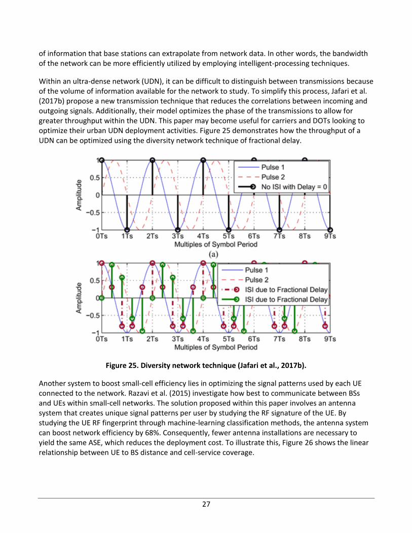
27
of information that base stations can extrapolate from network data. In other words, the bandwidth of the network can be more efficiently utilized by employing intelligent-processing techniques.
Within an ultra-dense network (UDN), it can be difficult to distinguish between transmissions because of the volume of information available for the network to study. To simplify this process, Jafari et al. (2017b) propose a new transmission technique that reduces the correlations between incoming and outgoing signals. Additionally, their model optimizes the phase of the transmissions to allow for greater throughput within the UDN. This paper may become useful for carriers and DOTs looking to optimize their urban UDN deployment activities. Figure 25 demonstrates how the throughput of a UDN can be optimized using the diversity network technique of fractional delay.
Figure 25. Diversity network technique (Jafari et al., 2017b).
Another system to boost small-cell efficiency lies in optimizing the signal patterns used by each UE connected to the network. Razavi et al. (2015) investigate how best to communicate between BSs and UEs within small-cell networks. The solution proposed within this paper involves an antenna system that creates unique signal patterns per user by studying the RF signature of the UE. By studying the UE RF fingerprint through machine-learning classification methods, the antenna system can boost network efficiency by 68%. Consequently, fewer antenna installations are necessary to yield the same ASE, which reduces the deployment cost. To illustrate this, Figure 26 shows the linear relationship between UE to BS distance and cell-service coverage.
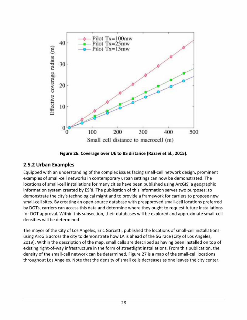
28
Figure 26. Coverage over UE to BS distance (Razavi et al., 2015).
2.5.2 Urban Examples
Equipped with an understanding of the complex issues facing small-cell network design, prominent examples of small-cell networks in contemporary urban settings can now be demonstrated. The locations of small-cell installations for many cities have been published using ArcGIS, a geographic information system created by ESRI. The publication of this information serves two purposes: to demonstrate the city’s technological might and to provide a framework for carriers to propose new small-cell sites. By creating an open-source database with preapproved small-cell locations preferred by DOTs, carriers can access this data and determine where they ought to request future installations for DOT approval. Within this subsection, their databases will be explored and approximate small-cell densities will be determined.
The mayor of the City of Los Angeles, Eric Garcetti, published the locations of small-cell installations using ArcGIS across the city to demonstrate how LA is ahead of the 5G race (City of Los Angeles, 2019). Within the description of the map, small cells are described as having been installed on top of existing right-of-way infrastructure in the form of streetlight installations. From this publication, the density of the small-cell network can be determined. Figure 27 is a map of the small-cell locations throughout Los Angeles. Note that the density of small cells decreases as one leaves the city center.
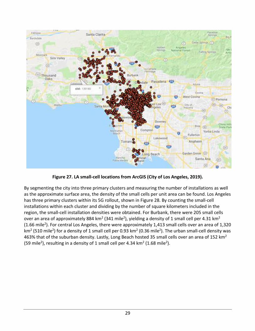
29
Figure 27. LA small-cell locations from ArcGIS (City of Los Angeles, 2019).
By segmenting the city into three primary clusters and measuring the number of installations as well as the approximate surface area, the density of the small cells per unit area can be found. Los Angeles has three primary clusters within its 5G rollout, shown in Figure 28. By counting the small-cell installations within each cluster and dividing by the number of square kilometers included in the region, the small-cell installation densities were obtained. For Burbank, there were 205 small cells over an area of approximately 884 km2 (341 mile2), yielding a density of 1 small cell per 4.31 km2 (1.66 mile2). For central Los Angeles, there were approximately 1,413 small cells over an area of 1,320 km2 (510 mile2) for a density of 1 small cell per 0.93 km2 (0.36 mile2). The urban small-cell density was 463% that of the suburban density. Lastly, Long Beach hosted 35 small cells over an area of 152 km2 (59 mile2), resulting in a density of 1 small cell per 4.34 km2 (1.68 mile2).

30
Figure 28. LA small-cell clusters (City of Los Angeles, 2019).
Boston and Denver have also published their small-cell locations using ArcGIS, and their data can be downloaded for analysis (DAS/Small Cell Approved Locations, 2019; Denver Public Works, 2019b). Each city yielded densities similar to those found for Los Angeles, though the interface deployed for each city varies and there were fewer tools available to analyze the data each site provided. Consequently, a more advanced study is needed to yield specific density studies for these regions. The Boston and Denver small-cell maps can be found in Figures 29 and 30, respectively.
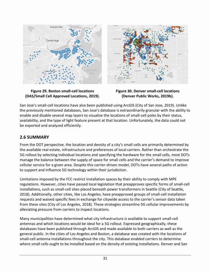
31
Figure 29. Boston small-cell locations (DAS/Small Cell Approved Locations, 2019).
Figure 30. Denver small-cell locations (Denver Public Works, 2019b).
San Jose’s small-cell locations have also been published using ArcGIS (City of San Jose, 2019). Unlike the previously mentioned databases, San Jose’s database is extraordinarily granular with the ability to enable and disable several map layers to visualize the locations of small-cell poles by their status, availability, and the type of light feature present at that location. Unfortunately, the data could not be exported and analyzed efficiently.
2.6 SUMMARY
From the DOT perspective, the location and density of a city’s small cells are primarily determined by the available real estate, infrastructure and preferences of local carriers. Rather than orchestrate the 5G rollout by selecting individual locations and specifying the hardware for the small cells, most DOTs manage the balance between the supply of space for small cells and the carrier’s demand to improve cellular service for a given area. Despite this carrier-driven model, DOTs have several paths of action to support and influence 5G technology within their jurisdiction.
Limitations imposed by the FCC restrict installation spaces by their ability to comply with MPE regulations. However, cities have passed local legislation that preapproves specific forms of small-cell installations, such as small-cell sites placed beneath power transformers in Seattle (City of Seattle, 2018). Additionally, other cities, like Los Angeles, have preapproved groups of small-cell installation requests and waived specific fees in exchange for citywide access to the carrier’s sensor data taken from these sites (City of Los Angeles, 2018). These strategies streamline 5G cellular improvements by alleviating pressure from carriers to inspect locations.
Many municipalities have determined what city infrastructure is available to support small-cell antennas and which locations would be ideal for a 5G rollout. Expressed geographically, these databases have been published through ArcGIS and made available to both carriers as well as the general public. In the cities of Los Angeles and Boston, a database was created with the locations of small-cell antenna installations throughout the city. This database enabled carriers to determine where small cells ought to be installed based on the density of existing installations. Denver and San
32
Jose developed a more robust solution to their small-cell location databases by zoning where small cells ought to be installed. They also added additional layers to their databases such as specific DOT jurisdictions and locations of municipal WiFi and camera poles. This allows carriers to more acutely contextualize small-cell locations by understanding how 5G will merge with the city’s existing infrastructure. By aggregating a database of preferred small-cell installation sites for the carriers, DOTs can efficiently cooperate with industrial actors.
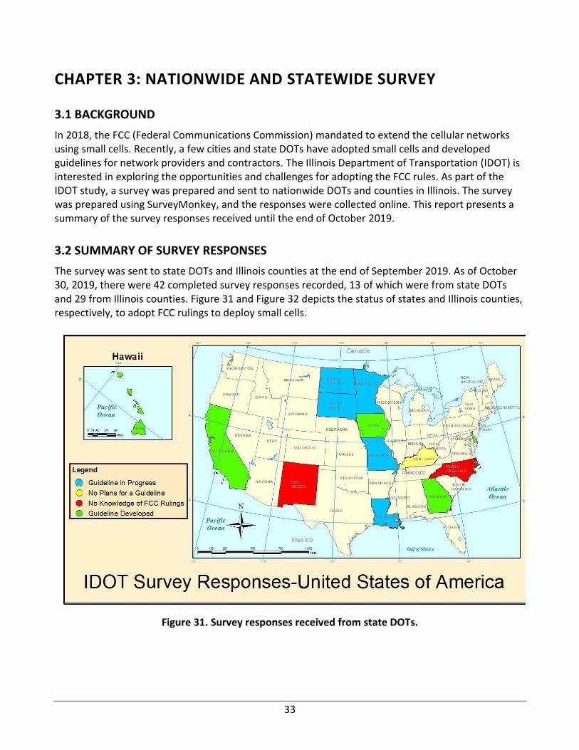
33
CHAPTER 3: NATIONWIDE AND STATEWIDE SURVEY
3.1 BACKGROUND
In 2018, the FCC (Federal Communications Commission) mandated to extend the cellular networks using small cells. Recently, a few cities and state DOTs have adopted small cells and developed guidelines for network providers and contractors. The Illinois Department of Transportation (IDOT) is interested in exploring the opportunities and challenges for adopting the FCC rules. As part of the IDOT study, a survey was prepared and sent to nationwide DOTs and counties in Illinois. The survey was prepared using SurveyMonkey, and the responses were collected online. This report presents a summary of the survey responses received until the end of October 2019.
3.2 SUMMARY OF SURVEY RESPONSES
The survey was sent to state DOTs and Illinois counties at the end of September 2019. As of October 30, 2019, there were 42 completed survey responses recorded, 13 of which were from state DOTs and 29 from Illinois counties. Figure 31 and Figure 32 depicts the status of states and Illinois counties, respectively, to adopt FCC rulings to deploy small cells.
Figure 31. Survey responses received from state DOTs.
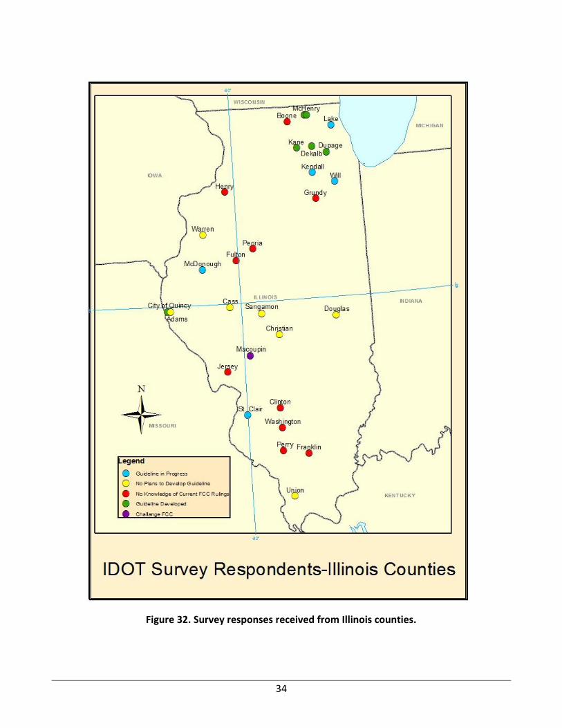
34
Figure 32. Survey responses received from Illinois counties.
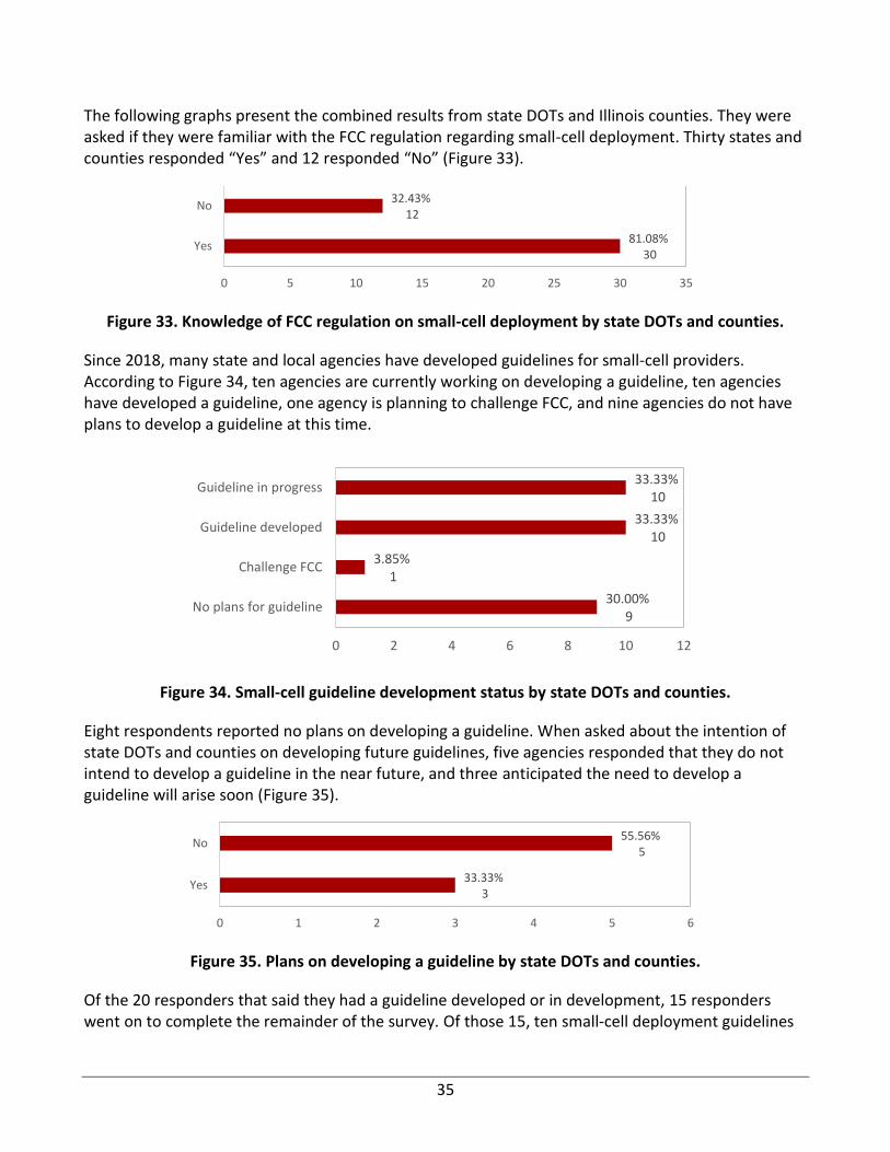
35
The following graphs present the combined results from state DOTs and Illinois counties. They were asked if they were familiar with the FCC regulation regarding small-cell deployment. Thirty states and counties responded “Yes” and 12 responded “No” (Figure 33).
Figure 33. Knowledge of FCC regulation on small-cell deployment by state DOTs and counties.
Since 2018, many state and local agencies have developed guidelines for small-cell providers. According to Figure 34, ten agencies are currently working on developing a guideline, ten agencies have developed a guideline, one agency is planning to challenge FCC, and nine agencies do not have plans to develop a guideline at this time.
Figure 34. Small-cell guideline development status by state DOTs and counties.
Eight respondents reported no plans on developing a guideline. When asked about the intention of state DOTs and counties on developing future guidelines, five agencies responded that they do not intend to develop a guideline in the near future, and three anticipated the need to develop a guideline will arise soon (Figure 35).
Figure 35. Plans on developing a guideline by state DOTs and counties.
Of the 20 responders that said they had a guideline developed or in development, 15 responders went on to complete the remainder of the survey. Of those 15, ten small-cell deployment guidelines
81.08%30
32.43%12
0 5 10 15 20 25 30 35
Yes
No
30.00%9
3.85%1
33.33%10
33.33%10
0 2 4 6 8 10 12
No plans for guideline
Challenge FCC
Guideline developed
Guideline in progress
33.33%3
55.56%5
0 1 2 3 4 5 6
Yes
No
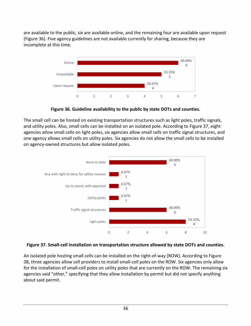
36
are available to the public, six are available online, and the remaining four are available upon request (Figure 36). Five agency guidelines are not available currently for sharing, because they are incomplete at this time.
Figure 36. Guideline availability to the public by state DOTs and counties.
The small cell can be hosted on existing transportation structures such as light poles, traffic signals, and utility poles. Also, small cells can be installed on an isolated pole. According to Figure 37, eight agencies allow small cells on light poles, six agencies allow small cells on traffic signal structures, and one agency allows small cells on utility poles. Six agencies do not allow the small cells to be installed on agency-owned structures but allow isolated poles.
Figure 37. Small-cell installation on transportation structure allowed by state DOTs and counties.
An isolated pole hosting small cells can be installed on the right-of-way (ROW). According to Figure 38, three agencies allow cell providers to install small-cell poles on the ROW. Six agencies only allow for the installation of small-cell poles on utility poles that are currently on the ROW. The remaining six agencies said “other,” specifying that they allow installation by permit but did not specify anything about said permit.
26.67%4
33.33%5
40.00%6
0 1 2 3 4 5 6 7
Upon request
Unavailable
Online
53.33%,8
40.00%6
6.67%1
6.67%,1
6.67%1
40.00%6
0 2 4 6 8 10
Light poles
Traffic signal structures
Utility poles
Up to owner with approval
Any with right to deny for safety reasons
None to date
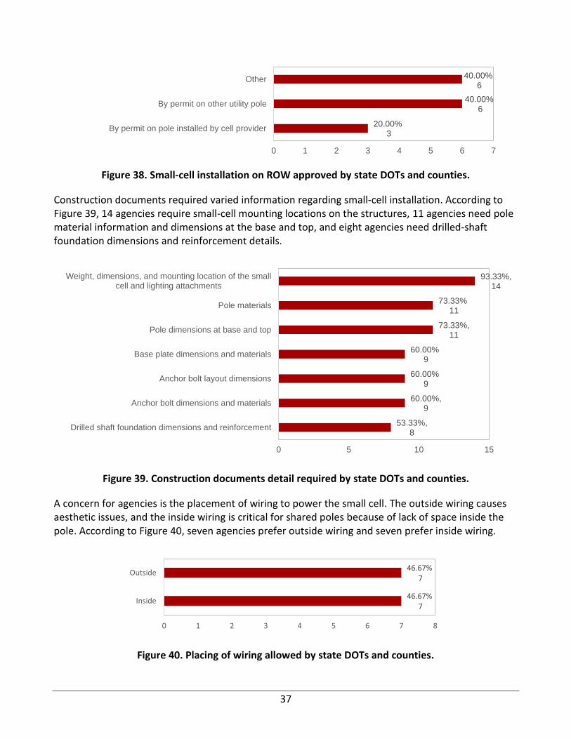
37
Figure 38. Small-cell installation on ROW approved by state DOTs and counties.
Construction documents required varied information regarding small-cell installation. According to Figure 39, 14 agencies require small-cell mounting locations on the structures, 11 agencies need pole material information and dimensions at the base and top, and eight agencies need drilled-shaft foundation dimensions and reinforcement details.
Figure 39. Construction documents detail required by state DOTs and counties.
A concern for agencies is the placement of wiring to power the small cell. The outside wiring causes aesthetic issues, and the inside wiring is critical for shared poles because of lack of space inside the pole. According to Figure 40, seven agencies prefer outside wiring and seven prefer inside wiring.
Figure 40. Placing of wiring allowed by state DOTs and counties.
20.00%3
40.00%6
40.00%6
0 1 2 3 4 5 6 7
By permit on pole installed by cell provider
By permit on other utility pole
Other
53.33%,8
60.00%,9
60.00%9
60.00%9
73.33%,11
73.33%11
93.33%,14
0 5 10 15
Drilled shaft foundation dimensions and reinforcement
Anchor bolt dimensions and materials
Anchor bolt layout dimensions
Base plate dimensions and materials
Pole dimensions at base and top
Pole materials
Weight, dimensions, and mounting location of the smallcell and lighting attachments
46.67%7
46.67%7
0 1 2 3 4 5 6 7 8
Inside
Outside

38
Underwriters Laboratories (UL) sets standards for product categories and tests products to ensure they meet those standards. According to Figure 41, 12 agencies reported that they do not require UL guidelines to install small cells, but most were unaware of whether there were any requirements.
Figure 41. UL guidelines requirement by state DOTs and counties.
A small cell has accessories that are placed either aboveground or underground. According to Figure 42, five agencies prefer aboveground accessories and three prefer underground. One agency specified ground-mounted boxes.
Figure 42. Location of electrical components preferred by state DOTs and counties.
Aesthetics are vital when considering small-cell installation in public spaces. A small cell consists of accessories that are exposed or hidden. Ten agencies responded that they have requirements on the aesthetics associated with small-cell deployment (Figure 43).
20.00%3
80.00%12
0 2 4 6 8 10 12 14
Yes
No
20.00%3
33.33%5
26.67%4
6.67%1
13.33%2
0 1 2 3 4 5 6
Underground
Aboveground
N/A /Not specified
Ground mounted box
Unknown
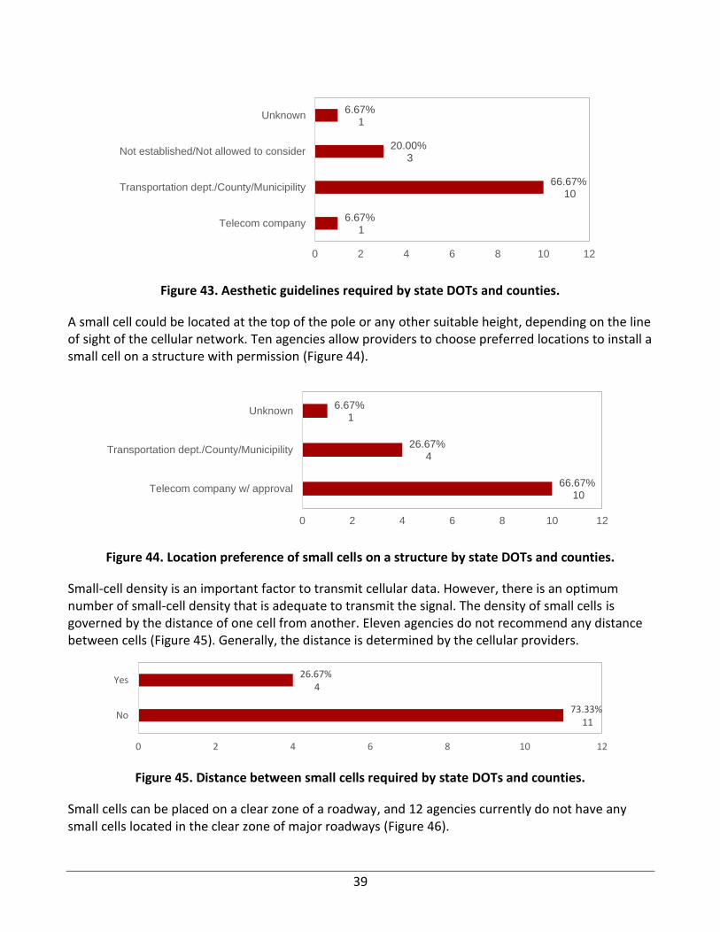
39
Figure 43. Aesthetic guidelines required by state DOTs and counties.
A small cell could be located at the top of the pole or any other suitable height, depending on the line of sight of the cellular network. Ten agencies allow providers to choose preferred locations to install a small cell on a structure with permission (Figure 44).
Figure 44. Location preference of small cells on a structure by state DOTs and counties.
Small-cell density is an important factor to transmit cellular data. However, there is an optimum number of small-cell density that is adequate to transmit the signal. The density of small cells is governed by the distance of one cell from another. Eleven agencies do not recommend any distance between cells (Figure 45). Generally, the distance is determined by the cellular providers.
Figure 45. Distance between small cells required by state DOTs and counties.
Small cells can be placed on a clear zone of a roadway, and 12 agencies currently do not have any small cells located in the clear zone of major roadways (Figure 46).
6.67%1
66.67%10
20.00%3
6.67%1
0 2 4 6 8 10 12
Telecom company
Transportation dept./County/Municipility
Not established/Not allowed to consider
Unknown
66.67%10
26.67%4
6.67%1
0 2 4 6 8 10 12
Telecom company w/ approval
Transportation dept./County/Municipility
Unknown
73.33%11
26.67%4
0 2 4 6 8 10 12
No
Yes
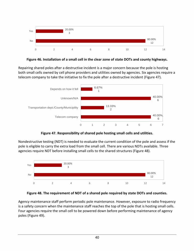
40
Figure 46. Installation of a small cell in the clear zone of state DOTs and county highways.
Repairing shared poles after a destructive incident is a major concern because the pole is hosting both small cells owned by cell phone providers and utilities owned by agencies. Six agencies require a telecom company to take the initiative to fix the pole after a destructive incident (Figure 47).
Figure 47. Responsibility of shared pole hosting small cells and utilities.
Nondestructive testing (NDT) is needed to evaluate the current condition of the pole and assess if the pole is eligible to carry the extra load from the small cell. There are various NDTs available. Three agencies require NDT before installing small cells to the shared structures (Figure 48).
Figure 48. The requirement of NDT of a shared pole required by state DOTs and counties.
Agency maintenance staff perform periodic pole maintenance. However, exposure to radio frequency is a safety concern when the maintenance staff reaches the top of the pole that is hosting small cells. Four agencies require the small cell to be powered down before performing maintenance of agency poles (Figure 49).
80.00%12
20.00%3
0 2 4 6 8 10 12 14
No
Yes
40.00%,6
13.33%2
40.00%6
6.67%1
0 1 2 3 4 5 6 7
Telecom company
Transportation dept./County/Municipility
Unknown/N/A
Depends on how it fell
80.00%12
20.00%3
0 2 4 6 8 10 12 14
No
Yes
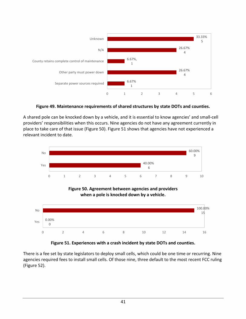
41
Figure 49. Maintenance requirements of shared structures by state DOTs and counties.
A shared pole can be knocked down by a vehicle, and it is essential to know agencies’ and small-cell providers’ responsibilities when this occurs. Nine agencies do not have any agreement currently in place to take care of that issue (Figure 50). Figure 51 shows that agencies have not experienced a relevant incident to date.
Figure 50. Agreement between agencies and providers when a pole is knocked down by a vehicle.
Figure 51. Experiences with a crash incident by state DOTs and counties.
There is a fee set by state legislators to deploy small cells, which could be one time or recurring. Nine agencies required fees to install small cells. Of those nine, three default to the most recent FCC ruling (Figure 52).
6.67%1
26.67%4
6.67%,1
26.67%4
33.33%5
0 1 2 3 4 5 6
Separate power sources required
Other party must power down
County retains complete control of maintenance
N/A
Unknown
40.00%6
60.00%9
0 1 2 3 4 5 6 7 8 9 10
Yes
No
0.00%0
100.00%15
0 2 4 6 8 10 12 14 16
Yes
No
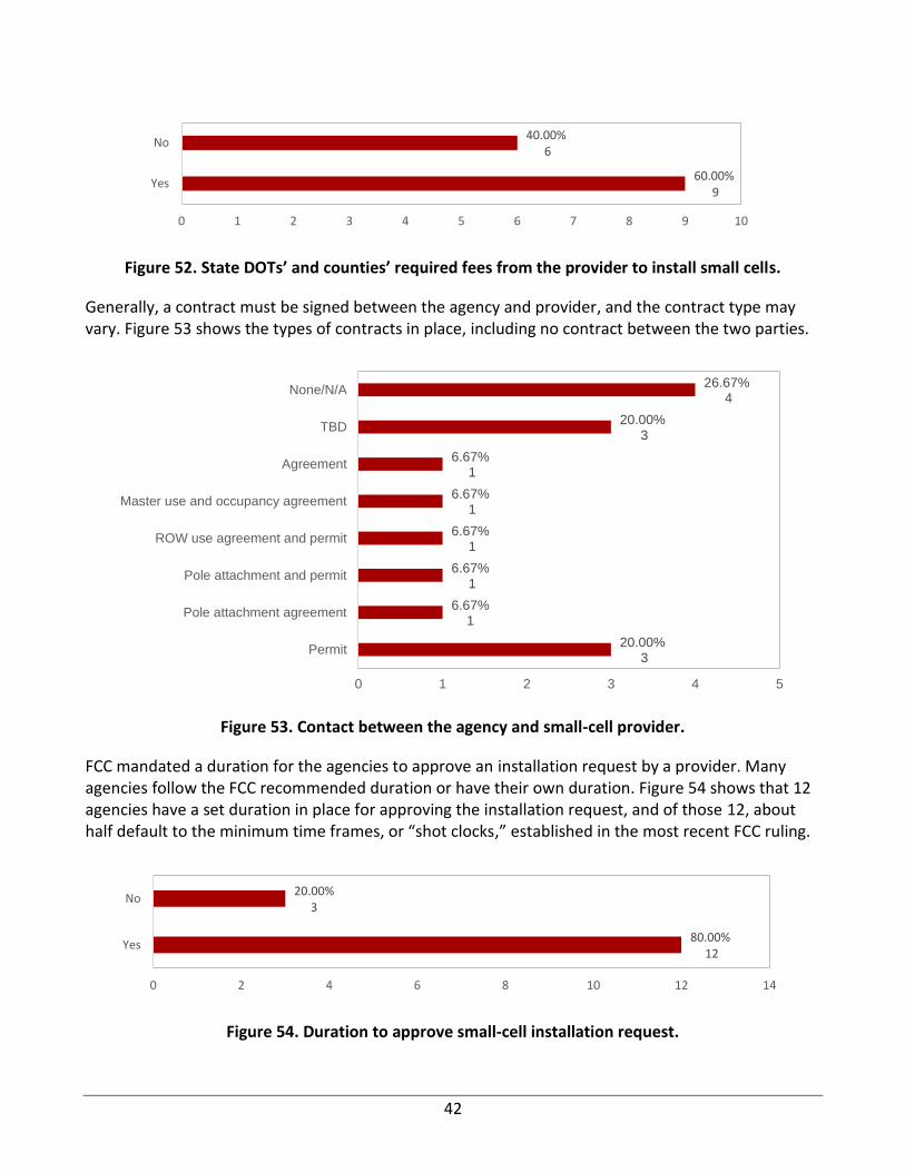
42
Figure 52. State DOTs’ and counties’ required fees from the provider to install small cells.
Generally, a contract must be signed between the agency and provider, and the contract type may vary. Figure 53 shows the types of contracts in place, including no contract between the two parties.
Figure 53. Contact between the agency and small-cell provider.
FCC mandated a duration for the agencies to approve an installation request by a provider. Many agencies follow the FCC recommended duration or have their own duration. Figure 54 shows that 12 agencies have a set duration in place for approving the installation request, and of those 12, about half default to the minimum time frames, or “shot clocks,” established in the most recent FCC ruling.
Figure 54. Duration to approve small-cell installation request.
60.00%9
40.00%6
0 1 2 3 4 5 6 7 8 9 10
Yes
No
20.00%3
6.67%1
6.67%1
6.67%1
6.67%1
6.67%1
20.00%3
26.67%4
0 1 2 3 4 5
Permit
Pole attachment agreement
Pole attachment and permit
ROW use agreement and permit
Master use and occupancy agreement
Agreement
TBD
None/N/A
80.00%12
20.00%3
0 2 4 6 8 10 12 14
Yes
No
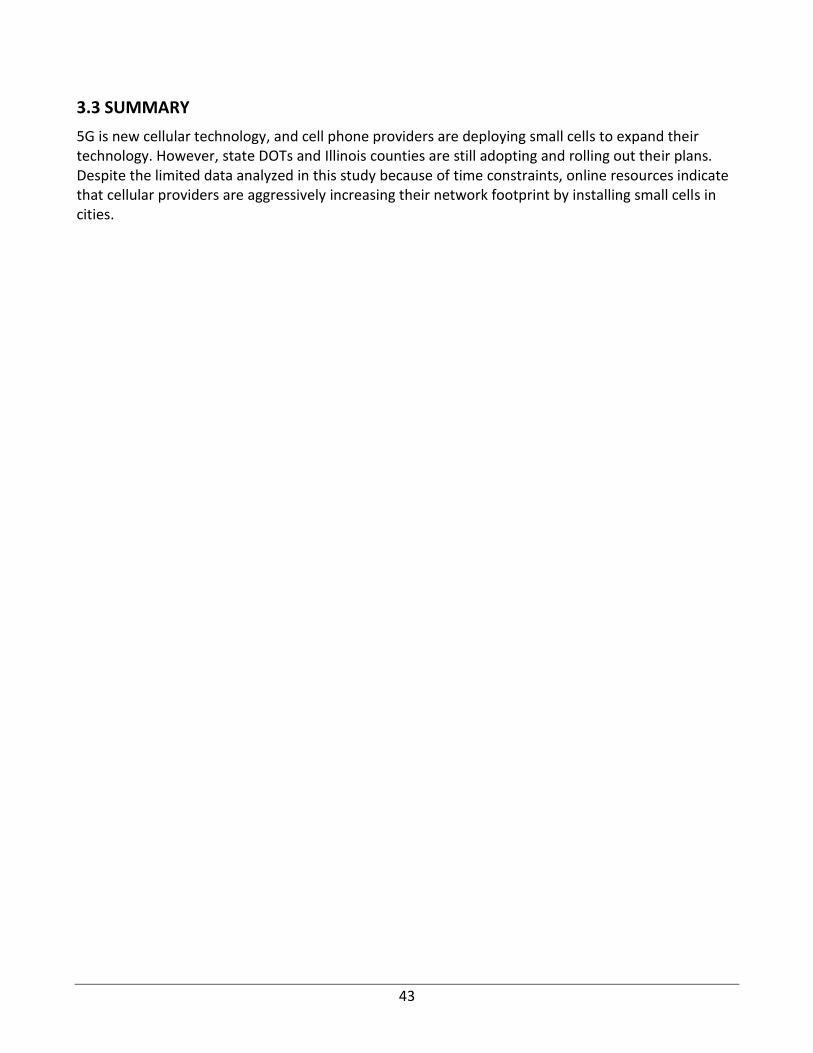
43
3.3 SUMMARY
5G is new cellular technology, and cell phone providers are deploying small cells to expand their technology. However, state DOTs and Illinois counties are still adopting and rolling out their plans. Despite the limited data analyzed in this study because of time constraints, online resources indicate that cellular providers are aggressively increasing their network footprint by installing small cells in cities.
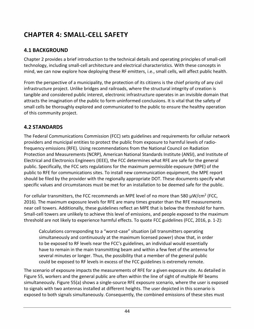
44
CHAPTER 4: SMALL-CELL SAFETY
4.1 BACKGROUND
Chapter 2 provides a brief introduction to the technical details and operating principles of small-cell technology, including small-cell architecture and electrical characteristics. With these concepts in mind, we can now explore how deploying these RF emitters, i.e., small cells, will affect public health.
From the perspective of a municipality, the protection of its citizens is the chief priority of any civil infrastructure project. Unlike bridges and railroads, where the structural integrity of creation is tangible and considered public interest, electronic infrastructure operates in an invisible domain that attracts the imagination of the public to form uninformed conclusions. It is vital that the safety of small cells be thoroughly explored and communicated to the public to ensure the healthy operation of this community project.
4.2 STANDARDS
The Federal Communications Commission (FCC) sets guidelines and requirements for cellular network providers and municipal entities to protect the public from exposure to harmful levels of radio-frequency emissions (RFE). Using recommendations from the National Council on Radiation Protection and Measurements (NCRP), American National Standards Institute (ANSI), and Institute of Electrical and Electronics Engineers (IEEE), the FCC determines what RFE are safe for the general public. Specifically, the FCC sets regulations for the maximum permissible exposure (MPE) of the public to RFE for communications sites. To install new communication equipment, the MPE report should be filed by the provider with the regionally appropriate DOT. These documents specify what specific values and circumstances must be met for an installation to be deemed safe for the public.
For cellular transmitters, the FCC recommends an MPE level of no more than 580 µW/cm2 (FCC, 2016). The maximum exposure levels for RFE are many times greater than the RFE measurements near cell towers. Additionally, these guidelines reflect an MPE that is below the threshold for harm. Small-cell towers are unlikely to achieve this level of emissions, and people exposed to the maximum threshold are not likely to experience harmful effects. To quote FCC guidelines (FCC, 2016, p. 1-2):
Calculations corresponding to a “worst-case” situation (all transmitters operating simultaneously and continuously at the maximum licensed power) show that, in order to be exposed to RF levels near the FCC’s guidelines, an individual would essentially have to remain in the main transmitting beam and within a few feet of the antenna for several minutes or longer. Thus, the possibility that a member of the general public could be exposed to RF levels in excess of the FCC guidelines is extremely remote.
The scenario of exposure impacts the measurements of RFE for a given exposure site. As detailed in Figure 55, workers and the general public are often within the line of sight of multiple RF beams simultaneously. Figure 55(a) shows a single-source RFE exposure scenario, where the user is exposed to signals with two antennas installed at different heights. The user depicted in this scenario is exposed to both signals simultaneously. Consequently, the combined emissions of these sites must
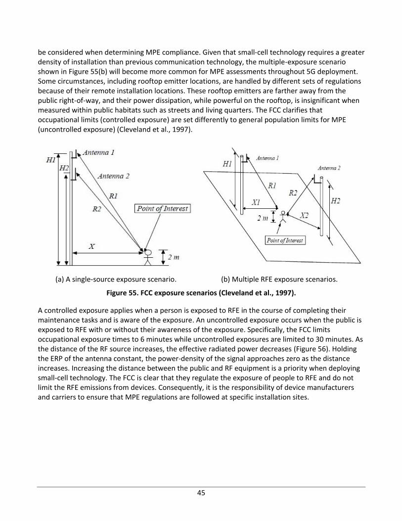
45
be considered when determining MPE compliance. Given that small-cell technology requires a greater density of installation than previous communication technology, the multiple-exposure scenario shown in Figure 55(b) will become more common for MPE assessments throughout 5G deployment. Some circumstances, including rooftop emitter locations, are handled by different sets of regulations because of their remote installation locations. These rooftop emitters are farther away from the public right-of-way, and their power dissipation, while powerful on the rooftop, is insignificant when measured within public habitats such as streets and living quarters. The FCC clarifies that occupational limits (controlled exposure) are set differently to general population limits for MPE (uncontrolled exposure) (Cleveland et al., 1997).
(a) A single-source exposure scenario. (b) Multiple RFE exposure scenarios.
Figure 55. FCC exposure scenarios (Cleveland et al., 1997).
A controlled exposure applies when a person is exposed to RFE in the course of completing their maintenance tasks and is aware of the exposure. An uncontrolled exposure occurs when the public is exposed to RFE with or without their awareness of the exposure. Specifically, the FCC limits occupational exposure times to 6 minutes while uncontrolled exposures are limited to 30 minutes. As the distance of the RF source increases, the effective radiated power decreases (Figure 56). Holding the ERP of the antenna constant, the power-density of the signal approaches zero as the distance increases. Increasing the distance between the public and RF equipment is a priority when deploying small-cell technology. The FCC is clear that they regulate the exposure of people to RFE and do not limit the RFE emissions from devices. Consequently, it is the responsibility of device manufacturers and carriers to ensure that MPE regulations are followed at specific installation sites.
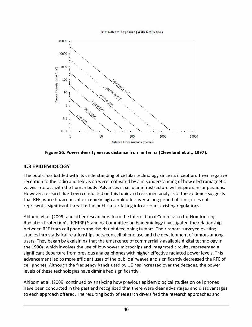
46
Figure 56. Power density versus distance from antenna (Cleveland et al., 1997).
4.3 EPIDEMIOLOGY
The public has battled with its understanding of cellular technology since its inception. Their negative reception to the radio and television were motivated by a misunderstanding of how electromagnetic waves interact with the human body. Advances in cellular infrastructure will inspire similar passions. However, research has been conducted on this topic and reasoned analysis of the evidence suggests that RFE, while hazardous at extremely high amplitudes over a long period of time, does not represent a significant threat to the public after taking into account existing regulations.
Ahlbom et al. (2009) and other researchers from the International Commission for Non-Ionizing Radiation Protection’s (ICNIRP) Standing Committee on Epidemiology investigated the relationship between RFE from cell phones and the risk of developing tumors. Their report surveyed existing studies into statistical relationships between cell phone use and the development of tumors among users. They began by explaining that the emergence of commercially available digital technology in the 1990s, which involves the use of low-power microchips and integrated circuits, represented a significant departure from previous analog phones with higher effective radiated power levels. This advancement led to more efficient uses of the public airwaves and significantly decreased the RFE of cell phones. Although the frequency bands used by UE has increased over the decades, the power levels of these technologies have diminished significantly.
Ahlbom et al. (2009) continued by analyzing how previous epidemiological studies on cell phones have been conducted in the past and recognized that there were clear advantages and disadvantages to each approach offered. The resulting body of research diversified the research approaches and
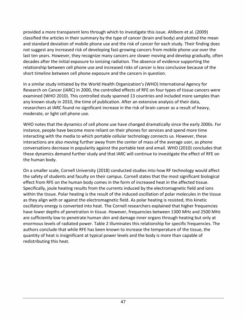
47
provided a more transparent lens through which to investigate this issue. Ahlbom et al. (2009) classified the articles in their summary by the type of cancer (brain and body) and plotted the mean and standard deviation of mobile phone use and the risk of cancer for each study. Their finding does not suggest any increased risk of developing fast-growing cancers from mobile phone use over the last ten years. However, they recognize many cancers are slower moving and develop gradually, often decades after the initial exposure to ionizing radiation. The absence of evidence supporting the relationship between cell phone use and increased risks of cancer is less conclusive because of the short timeline between cell phone exposure and the cancers in question.
In a similar study initiated by the World Health Organization’s (WHO) International Agency for Research on Cancer (IARC) in 2000, the controlled effects of RFE on four types of tissue cancers were examined (WHO 2010). This controlled study spanned 13 countries and included more samples than any known study in 2010, the time of publication. After an extensive analysis of their data, researchers at IARC found no significant increase in the risk of brain cancer as a result of heavy, moderate, or light cell phone use.
WHO notes that the dynamics of cell phone use have changed dramatically since the early 2000s. For instance, people have become more reliant on their phones for services and spend more time interacting with the media to which portable cellular technology connects us. However, these interactions are also moving further away from the center of mass of the average user, as phone conversations decrease in popularity against the portable text and email. WHO (2010) concludes that these dynamics demand further study and that IARC will continue to investigate the effect of RFE on the human body.
On a smaller scale, Cornell University (2018) conducted studies into how RF technology would affect the safety of students and faculty on their campus. Cornell states that the most significant biological effect from RFE on the human body comes in the form of increased heat in the affected tissue. Specifically, joule heating results from the currents induced by the electromagnetic field and ions within the tissue. Polar heating is the result of the induced oscillation of polar molecules in the tissue as they align with or against the electromagnetic field. As polar heating is resisted, this kinetic oscillatory energy is converted into heat. The Cornell researchers explained that higher frequencies have lower depths of penetration in tissue. However, frequencies between 1300 MHz and 2500 MHz are sufficiently low to penetrate human skin and damage inner organs through heating but only at enormous levels of radiated power. Table 2 illuminates this relationship for specific frequencies. The authors conclude that while RFE has been known to increase the temperature of the tissue, the quantity of heat is insignificant at typical power levels and the body is more than capable of redistributing this heat.
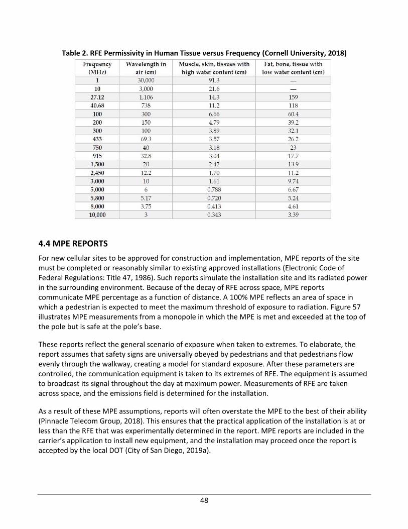
48
Table 2. RFE Permissivity in Human Tissue versus Frequency (Cornell University, 2018)
4.4 MPE REPORTS
For new cellular sites to be approved for construction and implementation, MPE reports of the site must be completed or reasonably similar to existing approved installations (Electronic Code of Federal Regulations: Title 47, 1986). Such reports simulate the installation site and its radiated power in the surrounding environment. Because of the decay of RFE across space, MPE reports communicate MPE percentage as a function of distance. A 100% MPE reflects an area of space in which a pedestrian is expected to meet the maximum threshold of exposure to radiation. Figure 57 illustrates MPE measurements from a monopole in which the MPE is met and exceeded at the top of the pole but is safe at the pole’s base.
These reports reflect the general scenario of exposure when taken to extremes. To elaborate, the report assumes that safety signs are universally obeyed by pedestrians and that pedestrians flow evenly through the walkway, creating a model for standard exposure. After these parameters are controlled, the communication equipment is taken to its extremes of RFE. The equipment is assumed to broadcast its signal throughout the day at maximum power. Measurements of RFE are taken across space, and the emissions field is determined for the installation.
As a result of these MPE assumptions, reports will often overstate the MPE to the best of their ability (Pinnacle Telecom Group, 2018). This ensures that the practical application of the installation is at or less than the RFE that was experimentally determined in the report. MPE reports are included in the carrier’s application to install new equipment, and the installation may proceed once the report is accepted by the local DOT (City of San Diego, 2019a).
49
Many of these MPE reports are freely available online and are published to educate the public and demonstrate transparency during the transition to 5G technology. Additionally, seeing as the carriers submit the requests for the installation of a new small-cell site, they often outsource the testing of their equipment to impartial third parties who simulate RFE fields and determine if the site is compliant with existing regulations. Within the scope of our study, several MPE reports are examined.
Figure 57. Crown MPE field for small-cell monopole (Crown Castle, 2019).
4.4.1 Pinnacle MPE Report
In Baltimore, Maryland, Crown Castle contracted Pinnacle Telecom Group to independently examine the MPE compliance of a Distributed Antenna System (DAS) in the metropolitan area (Pinnacle Telecom Group, 2018). Pinnacle explored three exposure scenarios for RF emissions:
• People standing below the antenna array.
• Antenna technicians working close to the antennas.
• People exposed to electromagnetic frequency (EMF) at the same height as the antenna (within buildings).
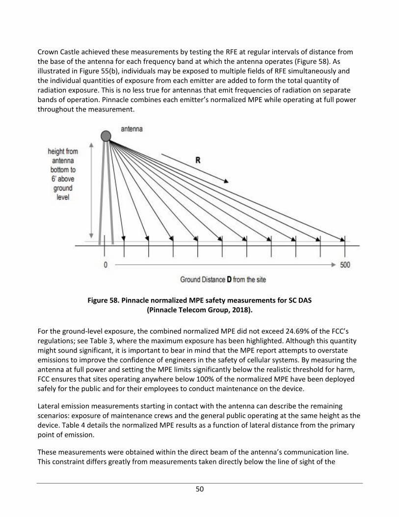
50
Crown Castle achieved these measurements by testing the RFE at regular intervals of distance from the base of the antenna for each frequency band at which the antenna operates (Figure 58). As illustrated in Figure 55(b), individuals may be exposed to multiple fields of RFE simultaneously and the individual quantities of exposure from each emitter are added to form the total quantity of radiation exposure. This is no less true for antennas that emit frequencies of radiation on separate bands of operation. Pinnacle combines each emitter’s normalized MPE while operating at full power throughout the measurement.
Figure 58. Pinnacle normalized MPE safety measurements for SC DAS (Pinnacle Telecom Group, 2018).
For the ground-level exposure, the combined normalized MPE did not exceed 24.69% of the FCC’s regulations; see Table 3, where the maximum exposure has been highlighted. Although this quantity might sound significant, it is important to bear in mind that the MPE report attempts to overstate emissions to improve the confidence of engineers in the safety of cellular systems. By measuring the antenna at full power and setting the MPE limits significantly below the realistic threshold for harm, FCC ensures that sites operating anywhere below 100% of the normalized MPE have been deployed safely for the public and for their employees to conduct maintenance on the device.
Lateral emission measurements starting in contact with the antenna can describe the remaining scenarios: exposure of maintenance crews and the general public operating at the same height as the device. Table 4 details the normalized MPE results as a function of lateral distance from the primary point of emission.
These measurements were obtained within the direct beam of the antenna’s communication line. This constraint differs greatly from measurements taken directly below the line of sight of the
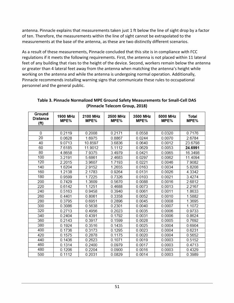
51
antenna. Pinnacle explains that measurements taken just 1 ft below the line of sight drop by a factor of ten. Therefore, the measurements within the line of sight cannot be extrapolated to the measurements at the base of the antenna, as these are two distinctly different scenarios.
As a result of these measurements, Pinnacle concluded that this site is in compliance with FCC regulations if it meets the following requirements. First, the antenna is not placed within 11 lateral feet of any building that rises to the height of the device. Second, workers remain below the antenna or greater than 4 lateral feet away from the antenna when matching the antenna’s height while working on the antenna and while the antenna is undergoing normal operation. Additionally, Pinnacle recommends installing warning signs that communicate these rules to occupational personnel and the general public.
Table 3. Pinnacle Normalized MPE Ground Safety Measurements for Small-Cell DAS (Pinnacle Telecom Group, 2018)
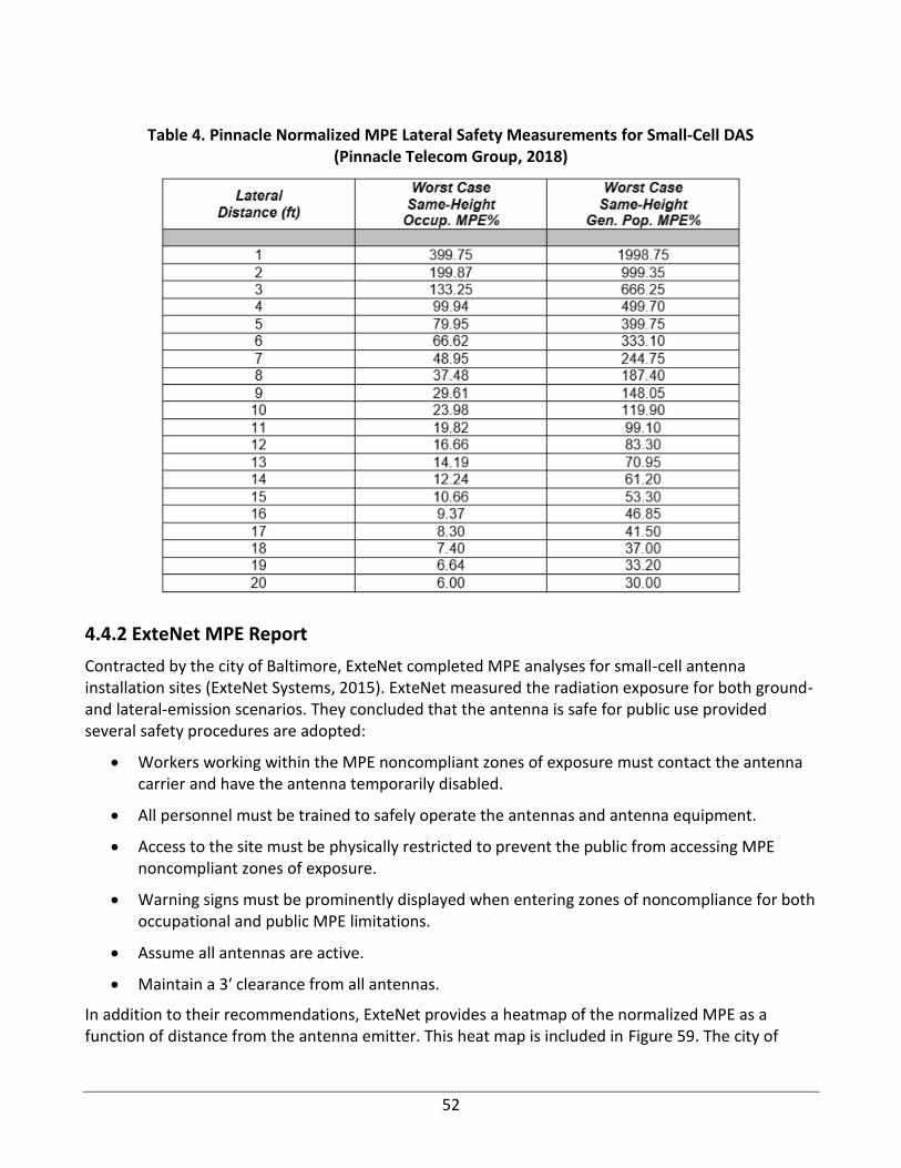
52
Table 4. Pinnacle Normalized MPE Lateral Safety Measurements for Small-Cell DAS (Pinnacle Telecom Group, 2018)
4.4.2 ExteNet MPE Report
Contracted by the city of Baltimore, ExteNet completed MPE analyses for small-cell antenna installation sites (ExteNet Systems, 2015). ExteNet measured the radiation exposure for both ground- and lateral-emission scenarios. They concluded that the antenna is safe for public use provided several safety procedures are adopted:
• Workers working within the MPE noncompliant zones of exposure must contact the antenna carrier and have the antenna temporarily disabled.
• All personnel must be trained to safely operate the antennas and antenna equipment.
• Access to the site must be physically restricted to prevent the public from accessing MPE noncompliant zones of exposure.
• Warning signs must be prominently displayed when entering zones of noncompliance for both occupational and public MPE limitations.
• Assume all antennas are active.
• Maintain a 3′ clearance from all antennas.
In addition to their recommendations, ExteNet provides a heatmap of the normalized MPE as a function of distance from the antenna emitter. This heat map is included in Figure 59. The city of
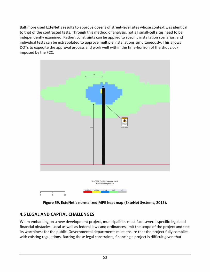
53
Baltimore used ExteNet’s results to approve dozens of street-level sites whose context was identical to that of the contracted tests. Through this method of analysis, not all small-cell sites need to be independently examined. Rather, constraints can be applied to specific installation scenarios, and individual tests can be extrapolated to approve multiple installations simultaneously. This allows DOTs to expedite the approval process and work well within the time-horizon of the shot clock imposed by the FCC.
Figure 59. ExteNet’s normalized MPE heat map (ExteNet Systems, 2015).
4.5 LEGAL AND CAPITAL CHALLENGES
When embarking on a new development project, municipalities must face several specific legal and financial obstacles. Local as well as federal laws and ordinances limit the scope of the project and test its worthiness for the public. Governmental departments must ensure that the project fully complies with existing regulations. Barring these legal constraints, financing a project is difficult given that
54
municipalities operate within a constrained budget. Within this chapter, several of the key legal and capital challenges facing departments of transportation (DOTs) are illuminated.
When pursuing its 5G ambitions, the City of San Diego asked the public for input into how and if 5G technology ought to be implemented in their city (City of San Diego, 2019c). Despite the many technological advantages that small-cell antennas offer the city, a large volume of the public input was focused on eliminating small cells to preserve public health. Despite these concerns, federal law prohibits SD-DOT from regulating small-cell placement based on environmental effects caused principally by RF emissions.
Specifically, some comments asserted that the installation of small cells represented discrimination against electrically sensitive people in violation of the Americans with Disabilities Act (ADA). This electrical sensitivity, known as Idiopathic Environmental Intolerance and attributed to electromagnetic fields (IEI-EMF), is so far medically unexplained. Verrender et al. (2018) found that subjects claiming to have IEI-EMF reported their symptoms to researchers when tested with sham and active electromagnetic field (EMF) exposures under two-way anonymous conditions. Despite strong beliefs in the test subjects that their irritations were caused by exposure to WiFi, no relationship was found between EMF exposure and IEI-EMF symptoms. However, a relationship was found between the belief of exposure and severity of symptoms. Although these studies do not reject IEI-EMF claims outright, the World Health Organization (WHO) supports the consensus among scientists that there is no scientific relationship between electrical sensitivity and EMF exposure (WHO, 2005).
Another complaint received by SD-DOT requested a moratorium on all small-cell installations throughout the city because of public health concerns regarding EMF exposure (City of San Diego, 2019c). The county notes that such a moratorium would be unfounded considering that small-cell installations do not pose a significant risk to the public. Additionally, local and federal laws prohibit authorities from regulating small-cell installations that comply with MPE limitations. The public opposition was significant enough to prompt the city to investigate related legal precedents.
To accelerate the proliferation of small cells, the FCC has significantly reduced the role of DOTs by limiting the regulation that DOTs provide. Consequently, the fee structure that city or local government provides is significantly lower than previous cellular infrastructure projects. This financial impact has led many municipalities to establish contracts directly with carriers to reap maximum benefits with the city such as those seen in Los Angeles (City of Los Angeles, 2018) and Seattle (City of Seattle, 2018). These contracts offer faster approval rates for carriers in exchange for open access to the data obtained by the new installations. Such agreements empower both parties and serve the public interest.
Carriers, on the other hand, recognize that there is significant financial gain in adapting their infrastructure. Public financial disclosures from carriers to investors have spoken of the upcoming financial rewards for 5G deployments. In 2014, Verizon wrote to investors in their 10-K, a financial report detailing the company’s financial performance, that they will continue to invest in small-cell technology through their vendors Alcatel-Lucent and Ericsson. The excitement for small-cell deployments is palpable as carriers have written to investors about small-cell technology in every
55
annual report over the last three years, see AT&T’s annual reports (AT&T Inc., 2017, 2018) and Verizon’s annual reports (Verizon 2016, 2017, 2018). Given that the carriers are provided with an incentive, 5G technology will flourish well into the next decade.
4.6 SUMMARY
The safety of the public with respect to new and existing communication equipment has long been the priority of the FCC and state DOTs. Leveraging the knowledge of several reputable scientific establishments, the FCC has developed rigorous and highly specific constraints dictating the parameters of approval and disapproval for small-cell sites.
Unfortunately, significant sectors of the public have not placed their confidence in these standards and cling to the hypothesis that cellular installations pose an imminent risk to the public. After thoroughly reviewing the available evidence, there is no significant body of observations to indicate that cell phones increase the risk of cancer for the public. Rather, as the frequency of a cellular signal increases, the permissivity of these signals into the human skin decreases, indicating that 5G bands might be safer than their archaic alternatives. However, despite this large body of evidence, humans have not been exposed to cellular communications long enough for true long-term epidemiological studies to yield a conclusion, and more work is needed. To the extent that cellular safety can be verified, the body of evidence and the consensus of scientists and engineers have confirmed that the risk posed is not significant.
Practically speaking, applicants use the MPE limits set by the FCC to judge the safety of individual small-cell installations. These MPE evaluations are often outsourced to independent third parties to preserve the impartiality of the analysis. The results of such safety inquiries include rules that carriers must adopt to ensure that the site is compliant with regulations. Because the distance of the subject from the antenna is the dominant variable in determining radiation exposure, the limitations placed on an antenna site revolve around the distance of the antenna from primary areas of interest, including adjacent buildings and walkways beneath an installation. If the EMF measured at these locations is less than or equal to the MPE limit for occupational or public exposure, then the site can be approved by the DOT and deployed.
Protocols have been established, tested, and studied to ensure that the public is not exposed to harmful quantities of radiation. In case members of the public are exposed to greater levels of MPE than permitted, the federal limitations are set such that the MPE limit is below the threshold for legitimate harm. Consequently, the existing regulations work to overprotect the public from equipment. Now that the nature of electromagnetic radiation (EMR) has been explored and solutions to the problem of safety have been explained, the locations that DOTs and cities determine for small-cell installation can be explored.
56
CHAPTER 5: SMALL-CELL CONSTRUCTION, OPERATION, AND MAINTENANCE
5.1 BACKGROUND
Small-cell permit documents collected from state DOTs and Illinois counties are either available online or upon request. Many documents are not currently available online because those are still under preparation or pending approval. Permit documents of Delaware State and McHenry County are available online (Delaware Department of Transportation, n.d.; McHenry County Division of Transportation 2012), but Louisiana State and Kane County are collected by email. Four permit documents are summarized in the following paragraphs.
5.2 CONSTRUCTION CONTRACTS OF SMALL-CELL INSTALLATION
The goal of this section is to identify challenges, opportunities, and conflicts between infrastructure and small-cell owners. Also, information on infrastructure design and construction, along with the installation of small cells, will be discussed. To do that, the following are addressed:
Contract details are a critical element between the owner of the infrastructure and network providers. Several major issues must be addressed to ensure smooth operation. First, the contract should consider the length of the agreement. This will protect both entities and allow for changes after a specified time. Another key element is how to terminate a contract. Both parties need to be comfortable with an exit strategy if need be. Other issues to be addressed are repercussions for a breach of contract. Specifics could be detailed, or a means to a solution could be given (i.e., mediation).
As for ownership, the contract should state that no subleasing of facilities is allowed. Wireless providers should also provide written notice of any sale or transfer of wireless facilities no less than 90 days prior to the transfer and provide the new owner’s information.
As with any contract, damage to property or personnel is critical and must be addressed. In this case, the licensee should not hold the state, county, or city liable for injuries or property damage. A clear set of rules and regulations should also be established that apply to both the infrastructure owner as well as the small-cell owners.
Routine maintenance should be addressed in the contract as well as who is responsible for repairs and what the proper workplace policies and procedures should be for all parties.
Finally, the transfer of information is important. Small-cell owners should provide infrastructure owners with relevant data that will ensure success for both parties.
Clearly defined responsibilities among the owners and providers must be established. The wireless provider and DOT should always meet in person to discuss issues when possible.
57
The following responsibilities should be clearly defined. First, the wireless provider should be onsite within a reasonable amount of time when notified of an emergency (less than three hours is sufficient). Second, the applicant is responsible for all necessary consultant review costs. Next, the wireless provider shall not participate in any illegal practices, anticompetitive behavior, or collusion with regard to construction activities related to the installation, operation, maintenance, transfer, relocation, or removal of the wireless facility and or equipment. The wireless provider is responsible for coordinating with utility companies to provide a separate service for the wireless facility. Finally, the wireless provider is responsible for locating potential utilities.
DOTs can host multiple providers. However, if only one facility can be located on a pole, whoever submitted the application first shall receive the right to use that location. The DOT has the right to have multiple providers for no extra cost as long as it is structurally stable.
The structural integrity of potential locations must be considered. In certain instances, wireless facility owners may be allowed to strengthen the DOT-owned towers at the wireless facility’s cost. Terms must be negotiated prior to permit approval. The wireless facility is responsible for maintaining the tower afterward.
The construction shop drawings should, at minimum, include the following as per DOT’s requirements:
• Legend for symbols/notation and scale
• Vicinity map with labeled roads
• Relevant local structures or features to installation
• Show new installations as highlighted image
• Give size, type, and description of installation i.e., 10″ PVC force main; 100 pair cable, etc.
• Show distance to the edge of highway pavement or centerline of the roadway to utility installation at increments of no less than 500′ and at least once on each plan sheet
• Show depth of cover for installation
• Show method of crossing over or under existing storm drains, or other utilities
• Give size and type of existing storm drain or utility to be crossed
• Method of crossing roads or highway
• Show existing location of utilities or other obstacles within the vicinity
• Differentiate between aerial vs. underground; existing vs. proposed
• Location of above-ground boxes
• Proposed guy wires shall be shown and placed outside of shoulders and ditch lines
• Provide other supporting information that is appropriate to plan and review
58
While nothing was addressed in terms of as-built drawings, a suggestion would be to require these for future contracts.
As for permit requirements, the wireless provider shall accept full responsibility for securing and maintaining all licenses and permits as applicable and required by law. The following is a list of items required for the permit:
• Site plan with drawings, including size, volume, surface area, height, and specifications of the proposed installation of the wireless communication facility and equipment.
• The site is not located within 25′ of any residential structure. Negotiated locations can occur if a site is within the 25′ limit.
• Device shall not extend beyond 10′ of the poles existing height.
• Device must be at least 10′ above the ground.
• All hardware and cabinets shall be painted to match or complement the structure upon which it is mounted.
• Must meet structural capacities.
When collocating, each installation must have its permit separate from the facility owner. The permits must be approved by engineers for work so as to not hurt the environment, and the FCC license must be submitted with the permit application.
The wireless provider shall obtain liability insurance of $1,000,000 per occurrence for bodily injury and property damage, and $3,000,000 general aggregate, including products/completed operations. The licensee should maintain commercial general liability insurance of $2,000,000 and property damage of $4,000,000 general aggregate. The licensee insurance will include the state, county, or city, its officers, and employees. All policies to be primary and noncontributory with any insurance or program of self-insurance may be maintained by the state, city, or county. The licensee may self-insure in accordance with the agreed-upon terms. The licensee will deposit $2,500 per wireless facility to guarantee the safe and efficient removal of any equipment from any collation subject to this agreement. Bonds are also required and shall be perpetual and may not be canceled without a release signed by the county. The licensee shall maintain the bond throughout the installation on the state, county, or city pole.
The cost to install small cells varies. Below are some guidelines found in contracts:
• Wireless provider shall pay a $100 fee for each small wireless facility when submitting a permit application.
• A yearly permit cost of $200 per each county facility to which equipment is attached.
• A wireless provider shall pay by electronic funds transfer.
• Licensee is responsible for additional costs to make the existing infrastructure work with their equipment.
• Recurring cost of $200 per year for the permit.

59
• Costs from one article
o Monopole/antenna—$2,000
o Attachment to existing utility/light pole—$1,500
o Colocation on tower—$3,500
The installation of small cells must be a combined effort. The wireless provider shall not locate facilities on decorative street poles or lights and should receive notice 30 days before it needs to be relocated or removed. If a new installation is required, then compaction requirements must be addressed, i.e., compaction requirements of 95% compaction where applicable to rough grading. Installation must be in accordance with local applicable codes. Also, cutting and trimming of trees, shrubs, etc. must be in accordance with department codes.
5.3 OPERATION, MAINTENANCE, AND SAFETY OF INFRASTRUCTURE AND SMALL CELLS
The goal of this section is to identify challenges in the operation and maintenance of a shared transportation infrastructure after installing small cells. Maintenance coordination between structure owners and small-cell owners must be clearly defined. The licensee must accept a transfer of maintenance on the state, county, or city property with terms related to that. The county or state must maintain its poles or replace poles as necessary to fulfill its service requirements. Lane closures will require a permit when maintenance is being performed. Access to the facilities should include the number of times access will be required and to what extent.
In the event that a fire, collision, or other unpredictable event shall disrupt the wireless facility, the wireless provider is allowed to terminate the permit with 15 days of written notice.
Removal of abandoned structures or small cells is the responsibility of the small-cell provider, and a specified time should be in the contract. If a site has been abandoned for six months or more, this is grounds for termination of the agreement by the department. If a contract expires, the wireless provider shall have 90 days to remove all equipment and personal property after the expiration of the term.
Damage of structures because of the installation of small cells should not occur, and there should be no interference with any other equipment used by a public safety agency.
All work is subject to inspection after having been erected. Inspection requirements should be outlined.
If a structure or small cell needs to be replaced, the wireless provider shall not install any new poles, monopoles, or similar structures or wireless provider equipment without being specifically authorized.
The safety of pedestrians, motorists, and vehicles is of the utmost importance. State, county, or city officials reserve the right to stop all work if it is deemed unsafe to the public or roadways. During installation, construction, and maintenance of small wireless facilities, the wireless provider shall
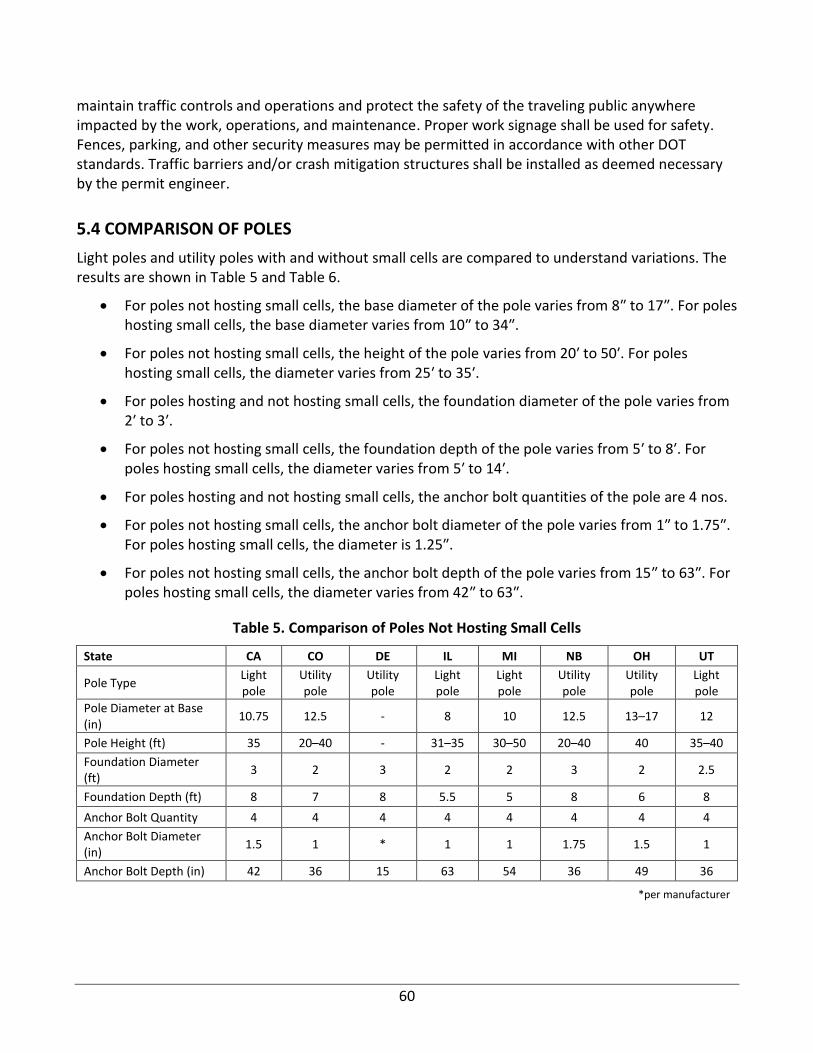
60
maintain traffic controls and operations and protect the safety of the traveling public anywhere impacted by the work, operations, and maintenance. Proper work signage shall be used for safety. Fences, parking, and other security measures may be permitted in accordance with other DOT standards. Traffic barriers and/or crash mitigation structures shall be installed as deemed necessary by the permit engineer.
5.4 COMPARISON OF POLES
Light poles and utility poles with and without small cells are compared to understand variations. The results are shown in Table 5 and Table 6.
• For poles not hosting small cells, the base diameter of the pole varies from 8″ to 17″. For poles hosting small cells, the base diameter varies from 10″ to 34″.
• For poles not hosting small cells, the height of the pole varies from 20′ to 50′. For poles hosting small cells, the diameter varies from 25′ to 35′.
• For poles hosting and not hosting small cells, the foundation diameter of the pole varies from 2′ to 3′.
• For poles not hosting small cells, the foundation depth of the pole varies from 5′ to 8′. For poles hosting small cells, the diameter varies from 5′ to 14′.
• For poles hosting and not hosting small cells, the anchor bolt quantities of the pole are 4 nos.
• For poles not hosting small cells, the anchor bolt diameter of the pole varies from 1″ to 1.75″. For poles hosting small cells, the diameter is 1.25″.
• For poles not hosting small cells, the anchor bolt depth of the pole varies from 15″ to 63″. For poles hosting small cells, the diameter varies from 42″ to 63″.
Table 5. Comparison of Poles Not Hosting Small Cells
State CA CO DE IL MI NB OH UT
Pole Type Light pole
Utility pole
Utility pole
Light pole
Light pole
Utility pole
Utility pole
Light pole
Pole Diameter at Base (in)
10.75 12.5 - 8 10 12.5 13–17 12
Pole Height (ft) 35 20–40 - 31–35 30–50 20–40 40 35–40
Foundation Diameter (ft)
3 2 3 2 2 3 2 2.5
Foundation Depth (ft) 8 7 8 5.5 5 8 6 8
Anchor Bolt Quantity 4 4 4 4 4 4 4 4
Anchor Bolt Diameter (in)
1.5 1 * 1 1 1.75 1.5 1
Anchor Bolt Depth (in) 42 36 15 63 54 36 49 36
*per manufacturer
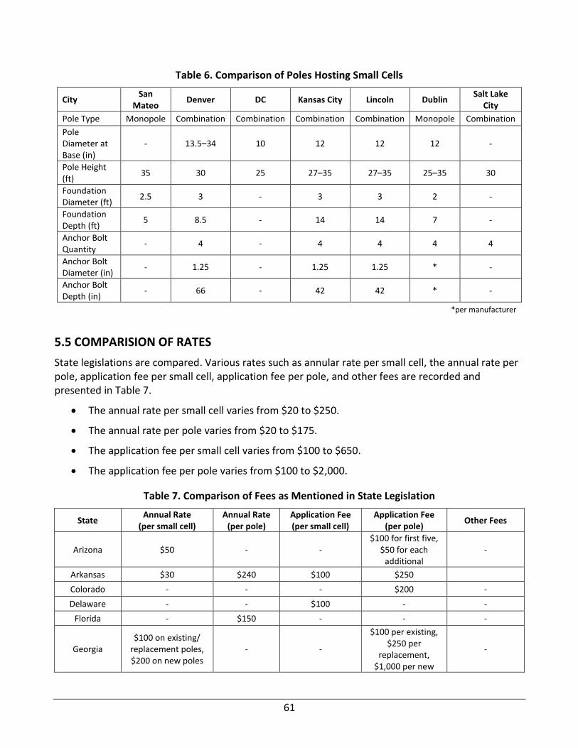
61
Table 6. Comparison of Poles Hosting Small Cells
City San
Mateo Denver DC Kansas City Lincoln Dublin
Salt Lake City
Pole Type Monopole Combination Combination Combination Combination Monopole Combination
Pole Diameter at Base (in)
- 13.5–34 10 12 12 12 -
Pole Height (ft)
35 30 25 27–35 27–35 25–35 30
Foundation Diameter (ft)
2.5 3 - 3 3 2 -
Foundation Depth (ft)
5 8.5 - 14 14 7 -
Anchor Bolt Quantity
- 4 - 4 4 4 4
Anchor Bolt Diameter (in)
- 1.25 - 1.25 1.25 * -
Anchor Bolt Depth (in)
- 66 - 42 42 * -
*per manufacturer
5.5 COMPARISION OF RATES
State legislations are compared. Various rates such as annular rate per small cell, the annual rate per pole, application fee per small cell, application fee per pole, and other fees are recorded and presented in Table 7.
• The annual rate per small cell varies from $20 to $250.
• The annual rate per pole varies from $20 to $175.
• The application fee per small cell varies from $100 to $650.
• The application fee per pole varies from $100 to $2,000.
Table 7. Comparison of Fees as Mentioned in State Legislation
State Annual Rate
(per small cell) Annual Rate
(per pole) Application Fee (per small cell)
Application Fee (per pole)
Other Fees
Arizona $50 - - $100 for first five,
$50 for each additional
-
Arkansas $30 $240 $100 $250
Colorado - - - $200 -
Delaware - - $100 - -
Florida - $150 - - -
Georgia $100 on existing/
replacement poles, $200 on new poles
- -
$100 per existing, $250 per
replacement, $1,000 per new
-
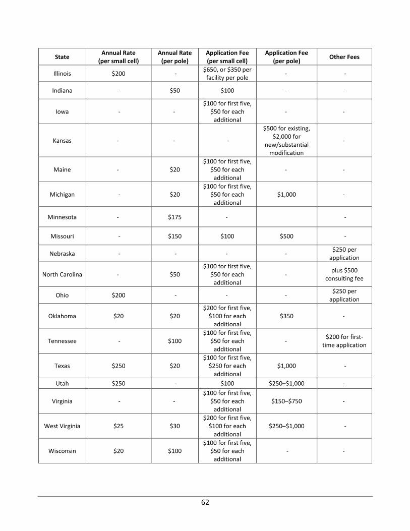
62
State Annual Rate
(per small cell) Annual Rate
(per pole) Application Fee (per small cell)
Application Fee (per pole)
Other Fees
Illinois $200 - $650, or $350 per
facility per pole - -
Indiana - $50 $100 - -
Iowa - - $100 for first five,
$50 for each additional
- -
Kansas - - -
$500 for existing, $2,000 for
new/substantial modification
-
Maine - $20 $100 for first five,
$50 for each additional
- -
Michigan - $20 $100 for first five,
$50 for each additional
$1,000 -
Minnesota - $175 - -
Missouri - $150 $100 $500 -
Nebraska - - - - $250 per
application
North Carolina - $50 $100 for first five,
$50 for each additional
- plus $500
consulting fee
Ohio $200 - - - $250 per
application
Oklahoma $20 $20 $200 for first five,
$100 for each additional
$350 -
Tennessee - $100 $100 for first five,
$50 for each additional
- $200 for first-
time application
Texas $250 $20 $100 for first five,
$250 for each additional
$1,000 -
Utah $250 - $100 $250–$1,000 -
Virginia - - $100 for first five,
$50 for each additional
$150–$750 -
West Virginia $25 $30 $200 for first five,
$100 for each additional
$250–$1,000 -
Wisconsin $20 $100 $100 for first five,
$50 for each additional
- -
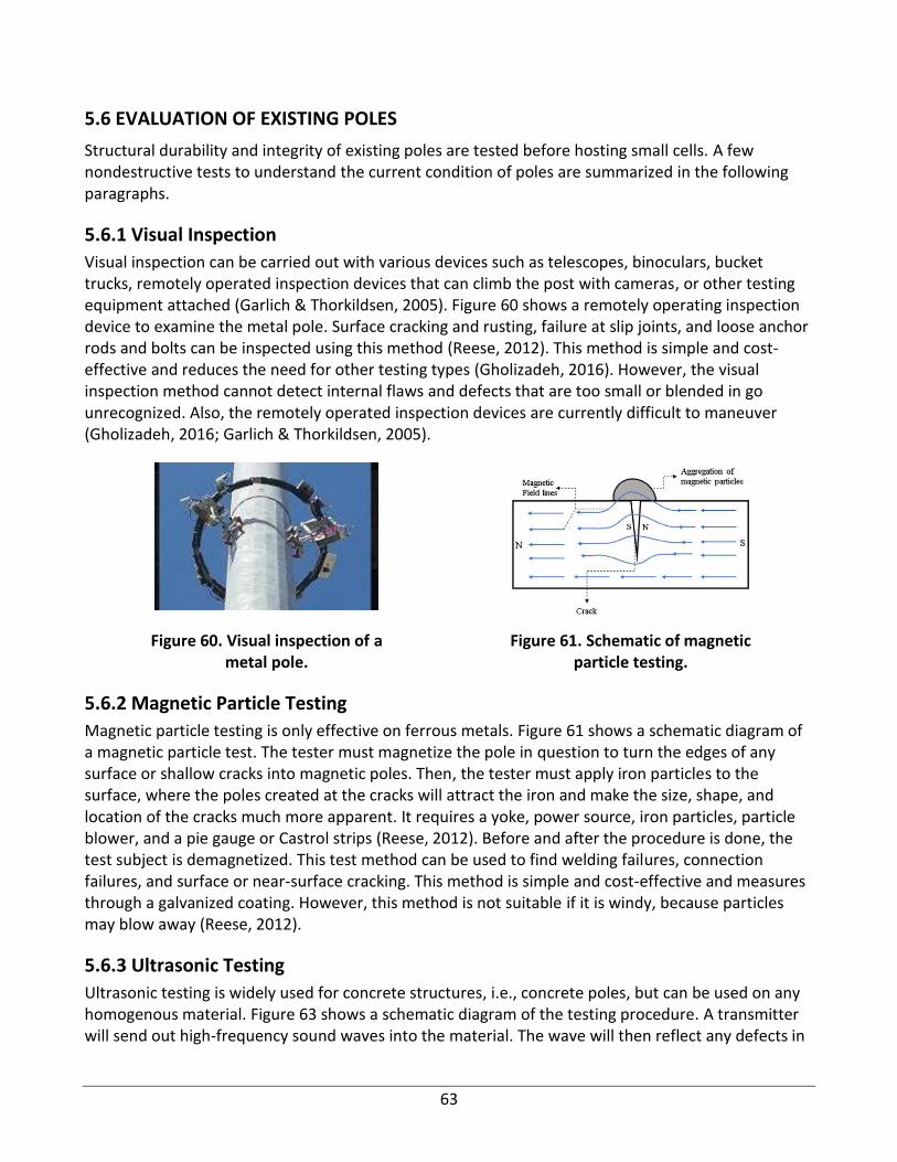
63
5.6 EVALUATION OF EXISTING POLES
Structural durability and integrity of existing poles are tested before hosting small cells. A few nondestructive tests to understand the current condition of poles are summarized in the following paragraphs.
5.6.1 Visual Inspection
Visual inspection can be carried out with various devices such as telescopes, binoculars, bucket trucks, remotely operated inspection devices that can climb the post with cameras, or other testing equipment attached (Garlich & Thorkildsen, 2005). Figure 60 shows a remotely operating inspection device to examine the metal pole. Surface cracking and rusting, failure at slip joints, and loose anchor rods and bolts can be inspected using this method (Reese, 2012). This method is simple and cost-effective and reduces the need for other testing types (Gholizadeh, 2016). However, the visual inspection method cannot detect internal flaws and defects that are too small or blended in go unrecognized. Also, the remotely operated inspection devices are currently difficult to maneuver (Gholizadeh, 2016; Garlich & Thorkildsen, 2005).
Figure 60. Visual inspection of a metal pole.
Figure 61. Schematic of magnetic particle testing.
5.6.2 Magnetic Particle Testing
Magnetic particle testing is only effective on ferrous metals. Figure 61 shows a schematic diagram of a magnetic particle test. The tester must magnetize the pole in question to turn the edges of any surface or shallow cracks into magnetic poles. Then, the tester must apply iron particles to the surface, where the poles created at the cracks will attract the iron and make the size, shape, and location of the cracks much more apparent. It requires a yoke, power source, iron particles, particle blower, and a pie gauge or Castrol strips (Reese, 2012). Before and after the procedure is done, the test subject is demagnetized. This test method can be used to find welding failures, connection failures, and surface or near-surface cracking. This method is simple and cost-effective and measures through a galvanized coating. However, this method is not suitable if it is windy, because particles may blow away (Reese, 2012).
5.6.3 Ultrasonic Testing
Ultrasonic testing is widely used for concrete structures, i.e., concrete poles, but can be used on any homogenous material. Figure 63 shows a schematic diagram of the testing procedure. A transmitter will send out high-frequency sound waves into the material. The wave will then reflect any defects in
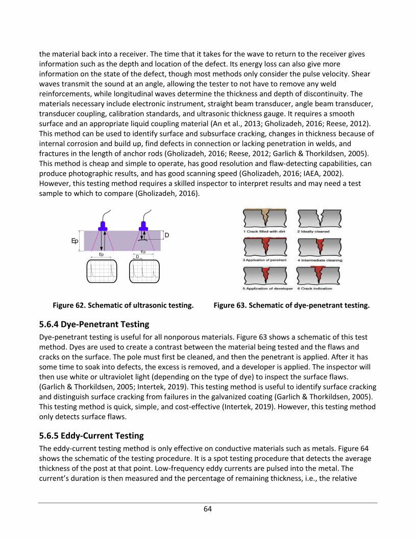
64
the material back into a receiver. The time that it takes for the wave to return to the receiver gives information such as the depth and location of the defect. Its energy loss can also give more information on the state of the defect, though most methods only consider the pulse velocity. Shear waves transmit the sound at an angle, allowing the tester to not have to remove any weld reinforcements, while longitudinal waves determine the thickness and depth of discontinuity. The materials necessary include electronic instrument, straight beam transducer, angle beam transducer, transducer coupling, calibration standards, and ultrasonic thickness gauge. It requires a smooth surface and an appropriate liquid coupling material (An et al., 2013; Gholizadeh, 2016; Reese, 2012). This method can be used to identify surface and subsurface cracking, changes in thickness because of internal corrosion and build up, find defects in connection or lacking penetration in welds, and fractures in the length of anchor rods (Gholizadeh, 2016; Reese, 2012; Garlich & Thorkildsen, 2005). This method is cheap and simple to operate, has good resolution and flaw-detecting capabilities, can produce photographic results, and has good scanning speed (Gholizadeh, 2016; IAEA, 2002). However, this testing method requires a skilled inspector to interpret results and may need a test sample to which to compare (Gholizadeh, 2016).
Figure 62. Schematic of ultrasonic testing. Figure 63. Schematic of dye-penetrant testing.
5.6.4 Dye-Penetrant Testing
Dye-penetrant testing is useful for all nonporous materials. Figure 63 shows a schematic of this test method. Dyes are used to create a contrast between the material being tested and the flaws and cracks on the surface. The pole must first be cleaned, and then the penetrant is applied. After it has some time to soak into defects, the excess is removed, and a developer is applied. The inspector will then use white or ultraviolet light (depending on the type of dye) to inspect the surface flaws. (Garlich & Thorkildsen, 2005; Intertek, 2019). This testing method is useful to identify surface cracking and distinguish surface cracking from failures in the galvanized coating (Garlich & Thorkildsen, 2005). This testing method is quick, simple, and cost-effective (Intertek, 2019). However, this testing method only detects surface flaws.
5.6.5 Eddy-Current Testing
The eddy-current testing method is only effective on conductive materials such as metals. Figure 64 shows the schematic of the testing procedure. It is a spot testing procedure that detects the average thickness of the post at that point. Low-frequency eddy currents are pulsed into the metal. The current’s duration is then measured and the percentage of remaining thickness, i.e., the relative
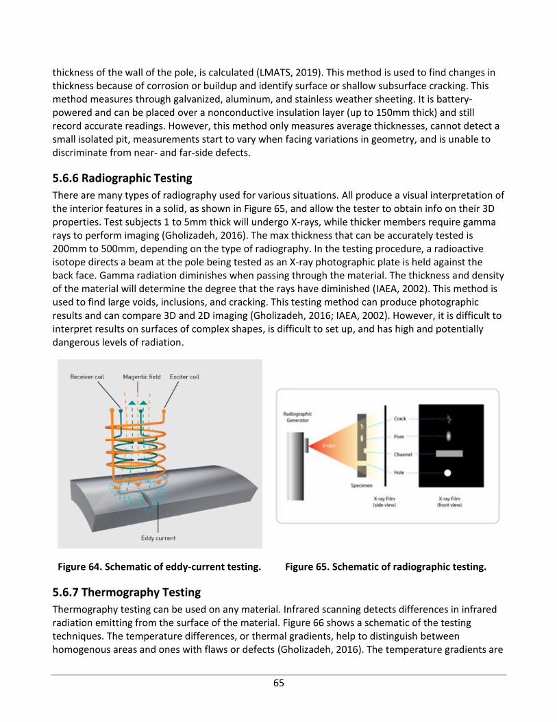
65
thickness of the wall of the pole, is calculated (LMATS, 2019). This method is used to find changes in thickness because of corrosion or buildup and identify surface or shallow subsurface cracking. This method measures through galvanized, aluminum, and stainless weather sheeting. It is battery-powered and can be placed over a nonconductive insulation layer (up to 150mm thick) and still record accurate readings. However, this method only measures average thicknesses, cannot detect a small isolated pit, measurements start to vary when facing variations in geometry, and is unable to discriminate from near- and far-side defects.
5.6.6 Radiographic Testing
There are many types of radiography used for various situations. All produce a visual interpretation of the interior features in a solid, as shown in Figure 65, and allow the tester to obtain info on their 3D properties. Test subjects 1 to 5mm thick will undergo X-rays, while thicker members require gamma rays to perform imaging (Gholizadeh, 2016). The max thickness that can be accurately tested is 200mm to 500mm, depending on the type of radiography. In the testing procedure, a radioactive isotope directs a beam at the pole being tested as an X-ray photographic plate is held against the back face. Gamma radiation diminishes when passing through the material. The thickness and density of the material will determine the degree that the rays have diminished (IAEA, 2002). This method is used to find large voids, inclusions, and cracking. This testing method can produce photographic results and can compare 3D and 2D imaging (Gholizadeh, 2016; IAEA, 2002). However, it is difficult to interpret results on surfaces of complex shapes, is difficult to set up, and has high and potentially dangerous levels of radiation.
Figure 64. Schematic of eddy-current testing. Figure 65. Schematic of radiographic testing.
5.6.7 Thermography Testing
Thermography testing can be used on any material. Infrared scanning detects differences in infrared radiation emitting from the surface of the material. Figure 66 shows a schematic of the testing techniques. The temperature differences, or thermal gradients, help to distinguish between homogenous areas and ones with flaws or defects (Gholizadeh, 2016). The temperature gradients are
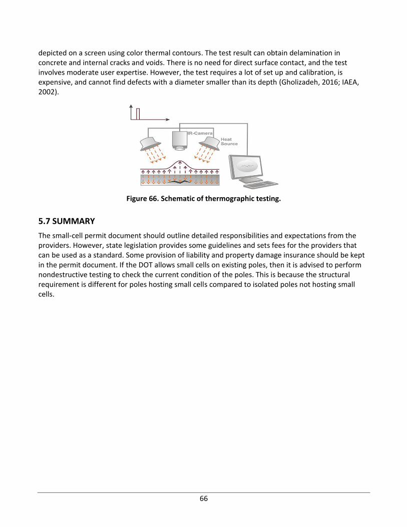
66
depicted on a screen using color thermal contours. The test result can obtain delamination in concrete and internal cracks and voids. There is no need for direct surface contact, and the test involves moderate user expertise. However, the test requires a lot of set up and calibration, is expensive, and cannot find defects with a diameter smaller than its depth (Gholizadeh, 2016; IAEA, 2002).
Figure 66. Schematic of thermographic testing.
5.7 SUMMARY
The small-cell permit document should outline detailed responsibilities and expectations from the providers. However, state legislation provides some guidelines and sets fees for the providers that can be used as a standard. Some provision of liability and property damage insurance should be kept in the permit document. If the DOT allows small cells on existing poles, then it is advised to perform nondestructive testing to check the current condition of the poles. This is because the structural requirement is different for poles hosting small cells compared to isolated poles not hosting small cells.
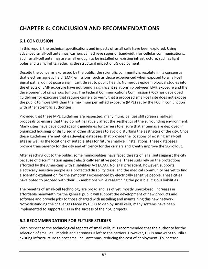
67
CHAPTER 6: CONCLUSION AND RECOMMENDATIONS
6.1 CONCLUSION
In this report, the technical specifications and impacts of small cells have been explored. Using advanced small-cell antennas, carriers can achieve superior bandwidth for cellular communications. Such small-cell antennas are small enough to be installed on existing infrastructure, such as light poles and traffic lights, reducing the structural impact of 5G deployment.
Despite the concerns expressed by the public, the scientific community is resolute in its consensus that electromagnetic field (EMF) emissions, such as those experienced when exposed to small-cell signal paths, do not pose a significant threat to public health. Numerous epidemiological studies into the effects of EMF exposure have not found a significant relationship between EMF exposure and the development of cancerous tumors. The Federal Communications Commission (FCC) has developed guidelines for exposure that require carriers to verify that a proposed small-cell site does not expose the public to more EMF than the maximum permitted exposure (MPE) set by the FCC in conjunction with other scientific authorities.
Provided that these MPE guidelines are respected, many municipalities still screen small-cell proposals to ensure that they do not negatively affect the aesthetics of the surrounding environment. Many cities have developed specific guidelines for carriers to ensure that antennas are deployed in organized housings or disguised in other structures to avoid disturbing the aesthetics of the city. Once these guidelines are met, cities develop databases that provide the locations of existing small-cell sites as well as the locations of suitable sites for future small-cell installations. These databases provide transparency for the city and efficiency for the carriers and greatly improve the 5G rollout.
After reaching out to the public, some municipalities have faced threats of legal suits against the city because of discrimination against electrically sensitive people. These suits rely on the protections afforded by the Americans with Disabilities Act (ADA). No legal precedent, however, supports electrically sensitive people as a protected disability class, and the medical community has yet to find a scientific explanation for the symptoms experienced by electrically sensitive people. These cities have opted to proceed with their 5G ambitions while researching the possible litigious liabilities.
The benefits of small-cell technology are broad and, as of yet, mostly unexplored. Increases in affordable bandwidth for the general public will support the development of new products and software and provide jobs to those charged with installing and maintaining this new network. Notwithstanding the challenges faced by DOTs to deploy small cells, many systems have been implemented to support DOTs in the success of their 5G projects.
6.2 RECOMMENDATION FOR FUTURE STUDIES
With respect to the technological aspects of small cells, it is recommended that the authority for the selection of small-cell models and antennas is left to the carriers. However, DOTs may want to utilize existing infrastructure to host small-cell antennas, reducing the cost of deployment. To increase
68
transparency, cellular carriers are to communicate to the public that 5G does not pose a significant risk, and all MPE reports for small-cell installations could be made a public record. As with the most successful 5G cities, municipalities should create a centralized database of existing and preferred small-cell installations. This database can exceed existing models by leveraging maps of population density and traffic flow patterns to intelligently deploy small-cell coverage where the city has the greatest demand and could reap the greatest benefit. Bradley University is well equipped to conduct such an analysis and deliver an intelligent database that improves coverage for all. There are legal challenges imposed by pursuing 5G technology, and these challenges could pose a threat to DOTs. By improving transparency and researching the legal case against small-cell deployment, DOTs can insulate themselves from these risks and safely pursue small-cell installation. Despite the reduction of oversight imposed by the FCC, DOTs may leverage their influence over the public infrastructure to create lucrative contracts with carriers that serve the general public. These recommendations are formed from the research included in this report and represent the cumulative efforts of multiple qualified engineers.
IDOT shall ensure that its employees receive a safety orientation and training prior to starting work on the maintenance of infrastructure hosting small cells. Safety guidelines can be created for training employees and identifying foreseeable emergency scenarios and nonroutine tasks, considering the types of material and equipment needed for each scenario. Scenarios such as the following may be foreseeable: structural collapse and nonroutine tasks, such as infrequently performed activities. IDOT can develop a clear plan and procedure for conducting incident investigations so that an investigation can begin immediately when an incident occurs.
69
REFERENCES
Ahlbom, A., Feychting, M., Green, A., Kheifets, L., Savitz, D. A., & Swerdlow, A. J. (2009). Epidemiology evidence on mobile phones and tumor risk: A review. Epidemiology, 20(5), 639–652. https://doi.org/10.1097/EDE.0b013e3181b0927d
Alouini, M. S., & Goldsmith, A. J. (1999). Area spectral efficiency of cellular mobile radio systems. IEEE Transactions on Vehicular Technology, 48(4), 1047–1066. https://doi.org/10.1109/25.775355
Amitec. (2018, July 12). Microstrip-Patch Antenna-Array-22 [Website]. Retrieved from https://amitec.co/microstrip-patch-antenna-array-22/
An, M., Sun, J., & Zhang, Y. Y. (2013). Research of ultrasonic thickness measurement method based on the pulse reflection type. Applied Mechanics and Materials, 380–384, 798–801. https://doi.org/10.4028/www.scientific.net/AMM.380-384.798
AT&T Inc. (2013). Photosimulation of proposed telecommunications site [Website]. Retrieved from AT&T Inc: https://www.sandiego.gov/sites/default/files/226649_sim.pdf
AT&T Inc. (2017). 2017 annual report. Retrieved from AT&T Inc: https://investors.att.com/~/media/Files/A/ATT-IR/financial-reports/annual-reports/2017/complete-2017-annual-report.pdf
AT&T Inc. (2018). 2018 annual report. Retrieved from AT&T Inc: https://investors.att.com/~/media/Files/A/ATT-IR/financial-reports/annual-reports/2018/complete-2018-annual-report.pdf
Bishop, D. (2017, May 24). Tower titans debate macro sites versus small cells [Website]. Retrieved from https://www.aglmediagroup.com/tower-titans-debate-macro-sites-versus-small-cells/
Center for Electrosmog Prevention. (n.d.). Ramona call to action: Stop 5G small cells [Website]. Retrieved from http://www.electrosmogprevention.org/international-electrosmog-prevention-news/ramona-call-to-action-stop-5g-small-cells/
City of Los Angeles. (2018). Second amendment to master permit for attachment of communication equipment to the City of Los Angeles street lighting poles. Retrieved from https://nextcenturycities.org/wp-content/uploads/los-angeles-small-cell-agreement.pdf
City of Los Angeles. (2019). City of Los Angeles: Small cell locations [Website]. Retrieved from https://data.lacity.org/A-Well-Run-City/Small-Cell-Locations/3nrm-mq6k
City of San Diego. (2019a). City of San Diego information bulletin 536. Submittal requirements and procedures for wireless communication facilities. Retrieved from City of San Diego Development Services Department: https://www.sandiego.gov/sites/default/files/dsdib536.pdf
City of San Diego. (2019b). City of San Diego land development manual: Wireless communications facilities (WCF) guidelines. Retrieved from the City of San Diego: https://www.sandiego.gov/sites/default/files/legacy/development-services/pdf/industry/telecomguide.pdf
City of San Diego. (2019c). Zoning ordinance update for small cell wireless facilities [Report]. The
70
County of San Diego Planning Commission Hearing Report. Retrieved from https://www.sandiegocounty.gov/content/dam/sdc/pds/advance/SmallCellWirelessFacilities/2019-07-18-PCReport.pdf
City of San Jose. (2019). City of San Jose: Small cell screening [Website]. Retrieved from https://csj.maps.arcgis.com/apps/webappviewer/index.html?id=7a5015dd4b0f4fba98e134d024150f2d&extent=-13568830.4132%2C4485969.6329%2C-13567922.7235%2C4486540.5219%2C102100
City of Seattle. (2018). Seattle city light construction standard (Standard Number 0095.15). Retrieved from http://www.seattle.gov/light/engstd/docs2/0095.15.pdf
Cleveland, R. F., Sylvar, D. M., & Ulcek, J. L. (1997). Evaluating compliance with FCC guidelines for human exposure to radiofrequency electromagnetic fields. OET Bulletin 65. Retrieved from Federal Communications Commission Office of Engineering & Technology: https://transition.fcc.gov/Bureaus/Engineering_Technology/Documents/bulletins/oet65/oet65.pdf
CommScope. (2018). Powering the future of small cells and beyond. Retrieved from https://www.commscope.com/Docs/Powering_5G_Cell_Densification_WP-112370-EN.pdf
Cornell University. (2018). RF and Microwave Safety Program. Retrieved from https://sp.ehs.cornell.edu/lab-research-safety/radiation/rf-microwaves/Documents/RF_microwave_safety_program.pdf
Crown Castle. (2019). RF emission compliance report [Website]. Retrieved from https://transportation.baltimorecity.gov/sites/default/files/Maximum% 20Permitted%20Exposure%20Report%20-%20All%20Carriers%20-%2028%20Port% 20Antenna.pdf
Daily Herald. (2018). Dupage proposes small cell antenna ordinance [Website]. Retrieved from https://www.dailyherald.com/news/20180619/dupage-proposes-small-cell-antenna-ordinance
DAS/Small Cell Approved Locations. (2019). [Website]. Retrieved from https://bostonopendata-boston.opendata.arcgis.com/datasets/ddb67bc9d9e246338778d40062448c23_0/data?geometry=-71.399%2C42.284%2C-70.746%2C42.372
Delaware Department of Transportation. (n.d.). Wireless small cell permits [Website]. Retrieved from https://deldot.gov/Business/WirelessPermits/index.shtml
Denver Public Works. (2019a). City and county of Denver: Small cell infrastructure design guidelines. Retrieved from Department of Public Works Engineering Division: https://www.denvergov.org/content/dam/denvergov/Portals/705/documents/guidelines/PWES-016.1-Small_Cell_Infrastructure_Design_Guidelines.pdf
Denver Public Works. (2019b). City and county of Denver: Small cell locations [Website]. Retrieved from https://www.arcgis.com/apps/webappviewer/index.html?id=0a1341b75cd54e7eb7179e661b1c9680
Desai, P. K., Keelgar, B. J. I., Kulkarni, K., & Kulkarni R. (2018). Antenna types for small cells base stations. International Journal of Science and Research, 7(9), 1351–1354. https://pdfs.semanticscholar.org/4a38/a766a40a6a7e5c79ee0828d44e00d26a3537.pdf
71
Ding, M., & Lopez-Perez, D. (2017). Performance impact of base station antenna heights in dense cellular networks. IEEE Transactions on Wireless Communications, 16(12), 8147–8161. https://doi.org/10.1109/TWC.2017.2757924
Electronic Code of Federal Regulations: Title 47. (1986). Actions that may have a significant environmental effect, for which environmental assessment (EAs) must be prepared [Website]. Retrieved from https://www.law.cornell.edu/cfr/text/47/1.1307
Electro Mechanical Industries, Inc. (EMI). (2019). Small 5G transmitters are showing up in Treasure Valley without notice. Here’s why [Website]. Retrieved from https://www.emiproducts.com/small-5g-transmitters-are-showing-up-in-treasure-valley-without-notice-heres-why/
EM Watch. (2020). Cell tower health risks [Website]. Retrieved from https://emwatch.com/cell-tower-health-risks/
EverythingRF. (2018, December 3). World’s first 28 GHz 5G single-panel antenna to simultaneously support multiple users [Website]. Retrieved from https://www.everythingrf.com/news/details /7281-World-s-First-28-GHz-5G-Single-Panel-Antenna-to-Simultaneously-Support-Multiple-Users
E’Ville Eye. (2018). March planning commission recap: At&T proposing ‘small cell’ towers to boost coverage; Adeline Springs update [Website]. Retrieved from https://evilleeye.com/news-commentary/march-planning-commission-recap-adeline-springs-update/
ExteNet Systems. (2015). Declaration of site MPE compliance [Website]. Retrieved from: http://transportation.baltimorecity.gov/sites/default/files/ExteNet%20Systems%20Inc.%20-%20NE-MD-BALTIMOR-SPR-2015.05.15_EME_COMPLIANCE_SITE_SAFE-e.pdf
Federal Communications Commission (FCC). (2016). Human exposure to radio frequency fields: Guidelines for cellular antenna sites. Retrieved from https://www.fcc.gov/consumers/guides /human-exposure-radio-frequency-fields-guidelines-cellular-and-pcs-sites
Federal Communications Commission (FCC). (2017a). Accelerating wireless broadband deployment by removing barriers to infrastructure investment (FCC-17-38) [Statement]. Retrieved from https://www.fcc.gov/document/wireless-infrastructure-nprm-and-noi/orielly-statement
Federal Communications Commission (FCC). (2017b). Accelerating wireline broadband deployment by removing barriers to infrastructure investment (WC Docket No. 17-84) [Fact sheet]. Retrieved from http://transition.fcc.gov/Daily_Releases/Daily_Business/2017/db1026/DOC-347451A1.pdf
Federal Communications Commission (FCC). (2018a). Declaratory ruling and third report and order, federal communications commission (FCC 18-133). Retrieved from https://docs.fcc.gov/public/attachments/FCC-18-133A1.pdf
Federal Communications Commission (FCC). (2018b). Accelerating wireline broadband deployment by removing barriers to infrastructure investment (WT Docket No. 17-79) [Final rule]. Retrieved from https://www.federalregister.gov/documents/2018/05/03/2018-08886/accelerating-wireless-broadband-deployment-by-removing-barriers-to-infrastructure-investment
Federal Communications Commission (FCC). (2019). The FCC’s 5G fast plan [Website]. Retrieved from https://www.fcc.gov/5G
72
Fiber Optic Association, Inc. (2018). Fiber optics for wireless—small cells [Website]. Retrieved from https://www.thefoa.org/tech/ref/appln/SmallCells.html
Garlich, M. J., & Thorkildsen, E. T. (2005). Guidelines for the installation, inspection, maintenance and repair of structural supports for highway signs, luminaires, and traffic signals (Report No. FHWA NHI 05-036). Retrieved from https://www.fhwa.dot.gov/bridge/signinspection.pdf
Gholizadeh, S. (2016). A review of non-destructive testing methods of composite materials. Procedia Structural Integrity, 1, 50–57. https://doi.org/10.1016/j.prostr.2016.02.008
Gibbs, C. (2016, September 16). California appeals court upholds small cells ruling against T-Mobile, Crown Castle. [Website]. Retrieved from https://www.fiercewireless.com/wireless/california-appeals-court-upholds-small-cells-ruling-against-t-mobile-crown-castle
GSMA. (n.d.). Improving wireless connectivity through small cell deployment. Retrieved from: https://www.gsma.com/publicpolicy/wp-content/uploads/2016/12/GSMA_Small_Cell _Deployment_Booklet.pdf
Haenggi, M. (2019). 4G wireless standard [Website]. Retrieved from https://www3.nd.edu /~mhaenggi/NET/wireless/4G/
Heilman, W. (2018). Small “towers” in Colorado Springs key to next-generation wireless service [Website]. Retrieved from https://gazette.com/business/small-towers-in-colorado-springs-key-to-next-generation-wireless/article_3f19a39d-67c9-5aa6-9676-9c1306b2f198.html
Huawei. (2016). Five trends to small cell 2020. Retrieved from http://www-file.huawei.com/~/media /CORPORATE/PDF/News/Five-Trends-To-Small-Cell-2020-en.pdf
Huber+Suhner. (n.d.). SENCITY® OMNI-S [Website]. Retrieved from https://www.hubersuhner.com /en/solutions/energy/products/wifi-antennas/sencity-omni-s
International Atomic Energy Agency (IAEA). (2002). Guidebook on non-destructive testing of concrete structures. International Atomic Energy Agency, Training Course Series No. 17, Vienna, Austria, https://www-pub.iaea.org/mtcd/publications/pdf/tcs-17_web.pdf
Intertek. (2019). Dye penetrant inspection [Website]. Retrieved from https://www.intertek.com/non-destructive-testing/dye-penetrant-inspection/
Jafari, A. H., Lopez-Perez, D., Ding, M., & Zhang, J. (2017a). Performance analysis of dense small cell networks with practical antenna height under ricing fading. IEEE Access, 6, 9960–9974. https://doi.org/10.1109/ACCESS.2017.2763613
Jafari, A. H., Venkateswaran, V., Perez-Lopez, D., & Zhang, J. (2017b). Diversity pulse shaped transmission in ultra-dense small cell networks. IEEE Transactions on Vehicular Technology, 66(7), 5866–5878. https://doi.org/10.1109/TVT.2016.2642162
Jamaly, N., Belanovic, P., Scanferla, D., Lehmann, H., & Genoud, C. (2017). Ultralwideband in-ground multiport antenna for small cell applications. IEEE Transactions on Antennas and Propagation, 65(5), 2318–2327. https://doi.org/10.1109/TAP.2017.2671020
Laboratory for Materials Advanced Testing Services (LMATS). (2019). Pulsed eddy current testing [Website]. Retrieved from https://lmats.com.au/services/advanced-ndt-solutions/pec-pulsed-
73
eddy-current-testing
Lasier, D., & VanDonkelaar, J. (2017). Small cell communications pole, system, and method. United States Patent No. US 9,837,698 B2. Retrieved from https://patentimages.storage.googleapis.com /95/5e/a8/7aa98470ca0307/US9837698.pdf
McHenry County Division of Transportation. (2012). McHenry County Division of Transportation Utility Consent Permit Application. Retrieved from https://www.mchenrycountyil.gov/home /showdocument?id=20363
National League of Cities. (2018). Municipal action guide: Small cell wireless technology in cities. Retrieved from https://www.nlc.org/sites/default/files/2018-08/CS_SmallCell_MAG_FINAL.pdf
NYM. (2020). Retrieved from https://nymfg.com/gallery/
Out of Home Advertising Association of America (OAAA). (2016). Wireless revenue for OOH assets: The reality [Website]. Retrieved from https://thoughtleadership.oaaa.org/wireless-revenue/
Peng, X., & Qiu, L. (2018). Analysis of multi-antenna small cell networks modeled by Gauss-Poisson process. IEEE Wireless Communications Letters, 7(5), 704–707. https://doi.org/10.1109/LWC.2018.2812854
Physics About. (2019). Destructive infrastructure [Website]. Retrieved from https://physicsabout.com/interface/
Pinnacle Telecom Group. (2018). Antenna site FCC RF compliance assessment and report [Report]. Retrieved from Pinnacle Telecom Group Professional and Technical Services: https://transportation.baltimorecity.gov/sites/default/files/Crown%20Castle%20Four-Carrier%20Location%20FCC%20Compliance%20Report.pdf
Positivity Naperville. (2017, November 7). Local leaders unite to urge ‘no’ for today’s small cell wireless bill [Website]. Retrieved from https://www.positivelynaperville.com/2017/11/07/local-leaders-unite-urge-no-todays-small-cell-wireless-bill/79788
Raycap. (2020). Raycap | STEALTH® Concealment Products [Website]. Retrieved from https://www.stealthconcealment.com/products/
Razavi, R., Ho, L., Claussen, H., & Lopez-Perez, D. (2015). Improving small-cell performance through switched multielement antenna systems in heterogeneous networks. IEEE Transactions on Vehicular Technology, 64(7), 3140–3151. https://doi.org/10.1109/TVT.2014.2348319
Reese, B. R. (2012). Non-destructive examination techniques of tubular steel pole sports lighting structures. ASCE Structural Congress, Las Vegas, NV, April 14–16. https://doi.org/10.1061/41171(401)150
RF Globalnet. (2019). ¼ Wave Whip Antenna (ANT-433-PW-QW) [Website]. Retrieved from https://www.rfglobalnet.com/doc/14-wave-whip-antenna-ant-433-pw-qw-0002
Small Cell Forum. (2018). Small cell siting challenges and recommendations. Retrieved from http://www.5gamericas.org/wp-content/uploads/2019/07/Small_Cell_Siting_Challenges __Recommendations_Whitepaper_final.pdf
Spivak, M. (2018, December 12). FCC denies motion for stay of small cell order [Website]. Retrieved
74
from Rural Spectrum Scanner: http://www.ruralspectrumscanner.com/fcc-denies-motion-for-stay-of-small-cell-order/
Statista. (2019). Number of mobile phone users in the U.S. from 2012 to 2020 (in millions) [Website]. Retrieved from https://www.statista.com/statistics/222306/forecast-of-smartphone-users-in-the-us/
Taco RC Store. (2019). Aomway 11dbi 7 Turn 5.8GHz Helical Antenna for FASTHARK LaForge TrueD Clearview [Website]. Retrieved from http://taco-rc.com/aomway-11dbi-7-turn-5-8ghz-helical-antenna-for-fatshark-laforge-trued-clearview/
Telecommunications Technical Services (TTS). (2019). DAS, Small cell & IoT [Website]. Retrieved from https://www.ttsvc.com/das-small-cell--iot.html
Tellus Venture Associates. (2016). Steve Blum’s Blog [Website]. Retrieved from https://www.tellusventure.com/blog/tag/pole-attachment/page/2/
ThinkSmallCell. (2017). JCDecaux offers multi-operator urban small cell solution [Website]. Retrieved from ThinkSmallCell: https://www.thinksmallcell.com/Urban/jcdecaux-offers-multi-operator-urban-small-cell-solution.html
Verizon. (2014). United States securities and exchange commission, Form 10-K. Retrieved from https://www.verizon.com/about/sites/default/files/2014_Form_10-K_-_As_Filed.pdf
Verizon. (2016). 2016 annual report. Retrieved from Verizon: https://www.verizon.com/about/sites /default/files/annual_reports/2016/downloads/Verizon-AnnualReport2016.pdf
Verizon. (2017). 2017 annual report. Retrieved from Verizon: https://www.verizon.com/about/sites /default/files/2017VerizonAnnualReport.pdf
Verizon. (2018). 2018 annual report. Retrieved from Verizon: https://www.verizon.com/about /sites/default/files/2018-Verizon-Annual-Report.pdf
Verrender, A., Loughran, S. P., Hillert, L., Rubin, G., & Croft, R. J. (2018). IEI-EMF provocation case studies: A novel approach to testing sensitive individuals. Bioelectromagnetics, 39(2), 132–143. https://doi.org/10.1002/bem.22095
Wade4Wireless. (2015). Outdoor small cell strand mount [Website]. Retrieved from https://wade4wireless.com/2015/07/06/outdoor-small-cell-strand-mount/
Wikimedia. (2014). North Park Water Tower [Website]. Retrieved from https://commons.wikimedia .org/wiki/File:North_Park_Water_Tower-2.jpg
Wireless Infrastructure Association. (2019). 28 states passed small cell legislation for 5G deployment [Website]. Retrieved from https://wia.org/smallcelllegislation/.
World Health Organization. (2005). Electromagnetic fields and public health: Electromagnetic hypersensitivity. Retrieved from https://www.who.int/peh-emf/publications/facts/fs296/en/
World Health Organization. (2010). Interphone study reports on mobile phone use and brain cancer risk [Press release]. Retrieved from International Agency for Research on Cancer: https://www.iarc.fr/wp-content/uploads/2018/07/pr200_E.pdf