sma rapid shutdown system - cloud object storage | … · sma rapid shutdown system rss-us-ia-xx-13...
TRANSCRIPT
SMA RAPID SHUTDOWN SYSTEM
RSS-US-IA-xx-13 | 101996-00.02 | Version 1.3
ENGLISH Installation Manual ESPAÑOL Instrucciones de instalación
Legal ProvisionsCopyright © 2016 SMA Solar Technology America LLC. All rights reserved.No part of this document may be reproduced, stored in a retrieval system, or transmitted, in anyform or by any means, be it electronic, mechanical, photographic, magnetic or otherwise, withoutthe prior written permission of SMA Solar Technology America LLC.Neither SMA Solar Technology America LLC nor SMA Solar Technology Canada Inc. makesrepresentations, express or implied, with respect to this documentation or any of the equipmentand/or software it may describe, including (with no limitation) any implied warranties of utility,merchantability, or fitness for any particular purpose. All such warranties are expressly disclaimed.Neither SMA Solar Technology America LLC nor its distributors or dealers nor SMA SolarTechnology Canada Inc. nor its distributors or dealers shall be liable for any indirect, incidental, orconsequential damages under any circumstances.(The exclusion of implied warranties may not apply in all cases under some statutes, and thus theabove exclusion may not apply.)Specifications are subject to change without notice. Every attempt has been made to make thisdocument complete, accurate and up-to-date. Readers are cautioned, however, that productimprovements and field usage experience may cause SMA Solar Technology America LLC and/orSMA Solar Technology Canada Inc. to make changes to these specifications without advancenotice, or per contract provisions in those cases where a supply agreement requires advancenotice. SMA shall not be responsible for any damages, including indirect, incidental orconsequential damages, caused by reliance on the material presented, including, but not limited to,omissions, typographical errors, arithmetical errors or listing errors in the content material.
TrademarksAll trademarks are recognized, even if not explicitly identified as such. Missing designations do notmean that a product or brand is not a registered trademark.Modbus® is a registered trademark of Schneider Electric and is licensed by theModbus Organization, Inc.QR Code is a registered trademark of DENSO WAVE INCORPORATED.Phillips® and Pozidriv® are registered trademarks of Phillips Screw Company.Torx® is a registered trademark of Acument Global Technologies, Inc.
SMA Solar Technology America LLC6020 West Oaks Blvd.
Suite 300 Rocklin, CA 95765 U.S.A.SMA Solar Technology Canada Inc.
2425 Matheson Blvd. E7th Floor
Mississauga, ON L4W 5K4Canada
Legal Provisions SMA Solar Technology America LLC
Installation ManualRSS-US-IA-xx-132
ENG
LISH
Important Safety InstructionsSAVE THESE INSTRUCTIONSThis manual contains important instructions for the following products:
• RSB-2S-US-10 (SMA Rapid Shutdown Box)• RSC-1X-US-10 (SMA Rapid Shutdown Controller)
This manual must be followed when using this product.
The product is designed and tested in accordance with international safety requirements, but aswith all electrical and electronic equipment, certain precautions must be observed when installingand/or operating the product. To reduce the risk of personal injury and to ensure the safeinstallation and operation of the product, you must carefully read and follow all instructions,cautions and warnings in this manual.
Warnings in this DocumentA warning describes a hazard to equipment or personnel. It calls attention to a procedure orpractice, which, if not correctly performed or adhered to, could result in damage to or destructionof part or all of the SMA equipment and/or other equipment connected to the SMA equipment orpersonal injury.
Symbol DescriptionDANGER indicates a hazardous situation which, if not avoided, willresult in death or serious injury.
WARNING indicates a hazardous situation which, if not avoided,could result in death or serious injury.
CAUTION indicates a hazardous situation which, if not avoided,could result in minor or moderate injury.
NOTICE is used to address practices not related to personal injury.
Warnings on this ProductThe following symbols are used as product markings with the following meanings.
Warning regarding dangerous voltageThe product works with high voltages. All work on the product must only be per-formed as described in the documentation of the product.
Beware of hot surfaceThe product can become hot during operation. Do not touch the product duringoperation.
Observe the operating instructionsRead the documentation of the product before working on it. Follow all safetyprecautions and instructions as described in the documentation.
Important Safety InstructionsSMA Solar Technology America LLC
Installation Manual 3RSS-US-IA-xx-13
ENG
LISH
General Warnings
All electrical installations must be carried out in accordance with the local electrical standardsand the National Electrical Code® ANSI/NFPA 70 or the Canadian Electrical Code®
CSA C22.1. This document does not replace and is not intended to replace any local, state,provincial, federal or national laws, regulations or codes applicable to the installation and use ofthe product, including without limitation applicable electrical safety codes. All installations mustconform with the laws, regulations, codes and standards applicable in the jurisdiction ofinstallation. SMA assumes no responsibility for the compliance or non-compliance with such lawsor codes in connection with the installation of the product. The product contains no user-serviceable parts. For all repair and maintenance, always return the unit to an authorized SMA Service Center. Before installing or using the product, read all of the instructions, cautions, and warnings in thismanual. Wiring of the product must be made by qualified personnel only.
General Warnings SMA Solar Technology America LLC
Installation ManualRSS-US-IA-xx-134
ENG
LISH
Table of Contents1 Information on this Document................................................. 7
1.1 Validity ............................................................................................... 71.2 Target group ...................................................................................... 71.3 Symbols.............................................................................................. 71.4 Nomenclature .................................................................................... 7
2 Safety ........................................................................................ 82.1 Intended Use...................................................................................... 82.2 Safety Information ............................................................................. 9
3 Scope of Delivery ..................................................................... 10
4 Product Description .................................................................. 114.1 Rapid Shutdown System.................................................................... 11
5 Mounting................................................................................... 135.1 Requirements for Mounting............................................................... 135.2 Mounting the Rapid Shutdown Box on a Mounting System........... 145.3 Mounting the Rapid Shutdown Box with Mounting Brackets ......... 165.4 Mounting the Rapid Shutdown Controller ....................................... 17
6 Electrical Connection ................................................................ 186.1 Safety during Electrical Connection ................................................. 186.2 Overview of the Rapid Shutdown Box Connection Area ............... 19
6.2.1 Exterior View ............................................................................... 196.2.2 Interior View ................................................................................ 20
6.3 Connecting the Equipment Grounding Conductor to the RapidShutdown Box.................................................................................... 20
6.4 Connecting the Rapid Shutdown Box and Rapid ShutdownController Together............................................................................ 22
6.5 Connecting Rapid Shutdown Boxes Together ................................. 276.6 Connecting the Strings to Rapid Shutdown Box.............................. 30
7 Commissioning the Rapid Shutdown System ........................ 34
8 Checking the Function of the Rapid Shutdown System......... 35
Table of ContentsSMA Solar Technology America LLC
Installation Manual 5RSS-US-IA-xx-13
ENG
LISH
9 Operating the Rapid Shutdown Controller............................ 369.1 Triggering the Rapid Shutdown Function ......................................... 369.2 Resetting the Rapid Shutdown Function ........................................... 36
10 Decommissioning the Rapid Shutdown System .................... 37
11 Technical Data .......................................................................... 4011.1 Rapid Shutdown Box......................................................................... 4011.2 Rapid Shutdown Controller............................................................... 40
12 Contact ...................................................................................... 42
13 Compliance Information .......................................................... 43
Table of Contents SMA Solar Technology America LLC
Installation ManualRSS-US-IA-xx-136
ENG
LISH
1 Information on this Document
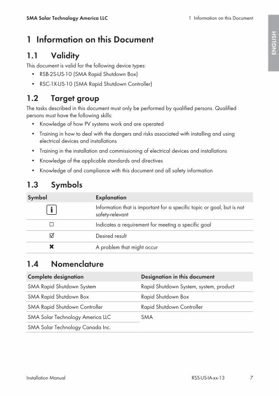
1.1 ValidityThis document is valid for the following device types:
• RSB-2S-US-10 (SMA Rapid Shutdown Box)• RSC-1X-US-10 (SMA Rapid Shutdown Controller)
1.2 Target groupThe tasks described in this document must only be performed by qualified persons. Qualifiedpersons must have the following skills:
• Knowledge of how PV systems work and are operated• Training in how to deal with the dangers and risks associated with installing and using
electrical devices and installations• Training in the installation and commissioning of electrical devices and installations• Knowledge of the applicable standards and directives• Knowledge of and compliance with this document and all safety information
1.3 SymbolsSymbol Explanation
Information that is important for a specific topic or goal, but is notsafety-relevant
Indicates a requirement for meeting a specific goal
Desired result
A problem that might occur
1.4 NomenclatureComplete designation Designation in this documentSMA Rapid Shutdown System Rapid Shutdown System, system, product
SMA Rapid Shutdown Box Rapid Shutdown Box
SMA Rapid Shutdown Controller Rapid Shutdown Controller
SMA Solar Technology America LLC SMA
SMA Solar Technology Canada Inc.
1 Information on this DocumentSMA Solar Technology America LLC
Installation Manual 7RSS-US-IA-xx-13
ENG
LISH
2 Safety
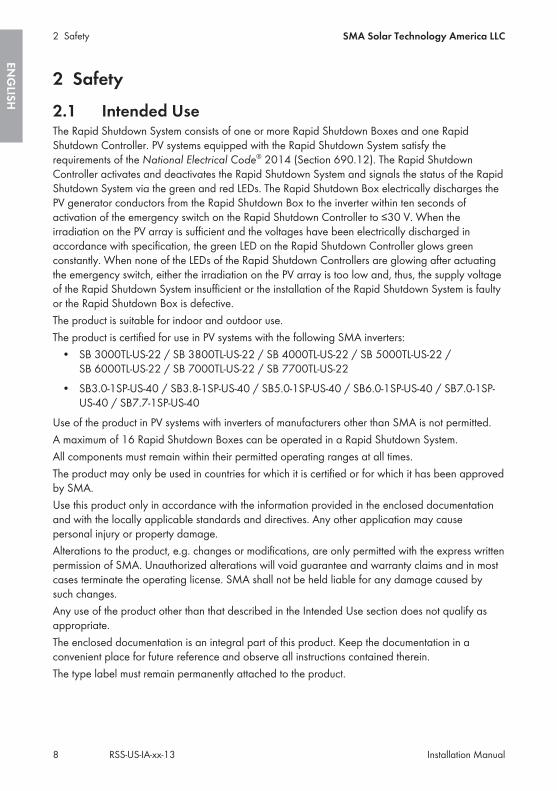
2.1 Intended UseThe Rapid Shutdown System consists of one or more Rapid Shutdown Boxes and one RapidShutdown Controller. PV systems equipped with the Rapid Shutdown System satisfy therequirements of the National Electrical Code® 2014 (Section 690.12). The Rapid ShutdownController activates and deactivates the Rapid Shutdown System and signals the status of the RapidShutdown System via the green and red LEDs. The Rapid Shutdown Box electrically discharges thePV generator conductors from the Rapid Shutdown Box to the inverter within ten seconds ofactivation of the emergency switch on the Rapid Shutdown Controller to ≤30 V. When theirradiation on the PV array is sufficient and the voltages have been electrically discharged inaccordance with specification, the green LED on the Rapid Shutdown Controller glows greenconstantly. When none of the LEDs of the Rapid Shutdown Controllers are glowing after actuatingthe emergency switch, either the irradiation on the PV array is too low and, thus, the supply voltageof the Rapid Shutdown System insufficient or the installation of the Rapid Shutdown System is faultyor the Rapid Shutdown Box is defective.The product is suitable for indoor and outdoor use.The product is certified for use in PV systems with the following SMA inverters:
• SB 3000TL-US-22 / SB 3800TL-US-22 / SB 4000TL-US-22 / SB 5000TL-US-22 /SB 6000TL-US-22 / SB 7000TL-US-22 / SB 7700TL-US-22
• SB3.0-1SP-US-40 / SB3.8-1SP-US-40 / SB5.0-1SP-US-40 / SB6.0-1SP-US-40 / SB7.0-1SP-US-40 / SB7.7-1SP-US-40
Use of the product in PV systems with inverters of manufacturers other than SMA is not permitted.A maximum of 16 Rapid Shutdown Boxes can be operated in a Rapid Shutdown System.All components must remain within their permitted operating ranges at all times.The product may only be used in countries for which it is certified or for which it has been approvedby SMA.Use this product only in accordance with the information provided in the enclosed documentationand with the locally applicable standards and directives. Any other application may causepersonal injury or property damage.Alterations to the product, e.g. changes or modifications, are only permitted with the express writtenpermission of SMA. Unauthorized alterations will void guarantee and warranty claims and in mostcases terminate the operating license. SMA shall not be held liable for any damage caused bysuch changes.Any use of the product other than that described in the Intended Use section does not qualify asappropriate.The enclosed documentation is an integral part of this product. Keep the documentation in aconvenient place for future reference and observe all instructions contained therein.The type label must remain permanently attached to the product.
2 Safety SMA Solar Technology America LLC
Installation ManualRSS-US-IA-xx-138
ENG
LISH

2.2 Safety InformationThis section contains safety information that must be observed at all times when working on or withthe product.To prevent personal injury and property damage and to ensure long-term operation of the product,read this section carefully and observe all safety information at all times.
Danger to life due to high voltages of the PV arrayWhen exposed to sunlight, the PV array generates dangerous DC voltage which is present in theDC conductors. Touching the DC conductors can lead to lethal electric shocks.
• Disconnect the DC connectors on the input strings.• Have the system mounted, installed and commissioned only by qualified persons with the
appropriate skills.• Only touch the DC cables on their insulation.• Do not touch the DC conductors.
Danger to life due to electric shock in case of a ground faultIf a ground fault occurs, parts of the system may still be live. Touching live components can leadto lethal electric shocks.
• Ensure that no voltage is present and wait five minutes before touching any parts of the PVsystem or of the Rapid Shutdown System.
2 SafetySMA Solar Technology America LLC
Installation Manual 9RSS-US-IA-xx-13
ENG
LISH
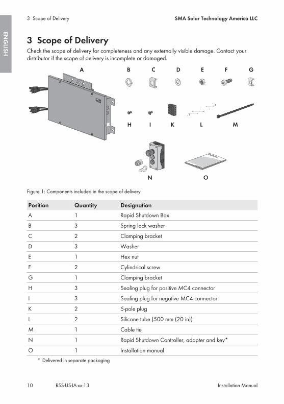
3 Scope of DeliveryCheck the scope of delivery for completeness and any externally visible damage. Contact yourdistributor if the scope of delivery is incomplete or damaged.
Figure 1: Components included in the scope of delivery
Position Quantity DesignationA 1 Rapid Shutdown Box
B 3 Spring lock washer
C 2 Clamping bracket
D 3 Washer
E 1 Hex nut
F 2 Cylindrical screw
G 1 Clamping bracket
H 3 Sealing plug for positive MC4 connector
I 3 Sealing plug for negative MC4 connector
K 2 5-pole plug
L 2 Silicone tube (500 mm (20 in))
M 1 Cable tie
N 1 Rapid Shutdown Controller, adapter and key*
O 1 Installation manual* Delivered in separate packaging
3 Scope of Delivery SMA Solar Technology America LLC
Installation ManualRSS-US-IA-xx-1310
ENG
LISH
4 Product Description
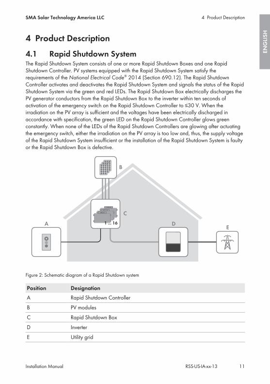
4.1 Rapid Shutdown SystemThe Rapid Shutdown System consists of one or more Rapid Shutdown Boxes and one RapidShutdown Controller. PV systems equipped with the Rapid Shutdown System satisfy therequirements of the National Electrical Code® 2014 (Section 690.12). The Rapid ShutdownController activates and deactivates the Rapid Shutdown System and signals the status of the RapidShutdown System via the green and red LEDs. The Rapid Shutdown Box electrically discharges thePV generator conductors from the Rapid Shutdown Box to the inverter within ten seconds ofactivation of the emergency switch on the Rapid Shutdown Controller to ≤30 V. When theirradiation on the PV array is sufficient and the voltages have been electrically discharged inaccordance with specification, the green LED on the Rapid Shutdown Controller glows greenconstantly. When none of the LEDs of the Rapid Shutdown Controllers are glowing after actuatingthe emergency switch, either the irradiation on the PV array is too low and, thus, the supply voltageof the Rapid Shutdown System insufficient or the installation of the Rapid Shutdown System is faultyor the Rapid Shutdown Box is defective.
A DE
1 ... 16
B
C
Figure 2: Schematic diagram of a Rapid Shutdown system
Position DesignationA Rapid Shutdown Controller
B PV modules
C Rapid Shutdown Box
D Inverter
E Utility grid
4 Product DescriptionSMA Solar Technology America LLC
Installation Manual 11RSS-US-IA-xx-13
ENG
LISH
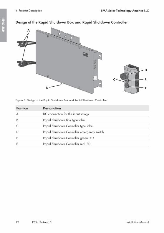
Design of the Rapid Shutdown Box and Rapid Shutdown Controller
Figure 3: Design of the Rapid Shutdown Box and Rapid Shutdown Controller
Position DesignationA DC connection for the input strings
B Rapid Shutdown Box type label
C Rapid Shutdown Controller type label
D Rapid Shutdown Controller emergency switch
E Rapid Shutdown Controller green LED
F Rapid Shutdown Controller red LED
4 Product Description SMA Solar Technology America LLC
Installation ManualRSS-US-IA-xx-1312
ENG
LISH
5 Mounting
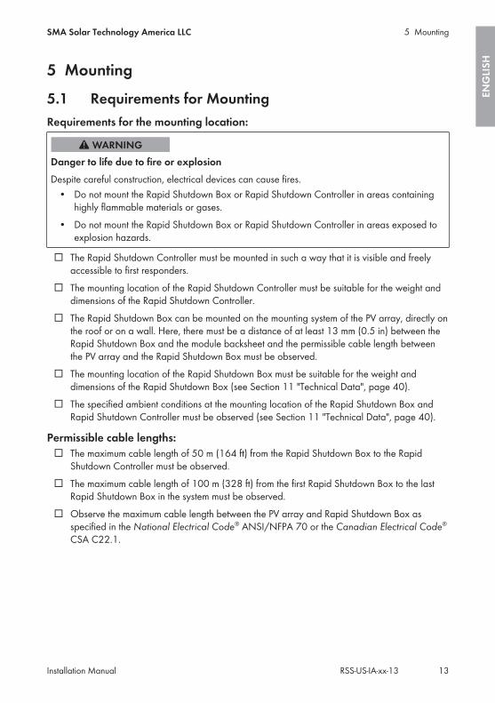
5.1 Requirements for MountingRequirements for the mounting location:
Danger to life due to fire or explosionDespite careful construction, electrical devices can cause fires.
• Do not mount the Rapid Shutdown Box or Rapid Shutdown Controller in areas containinghighly flammable materials or gases.
• Do not mount the Rapid Shutdown Box or Rapid Shutdown Controller in areas exposed toexplosion hazards.
☐ The Rapid Shutdown Controller must be mounted in such a way that it is visible and freelyaccessible to first responders.
☐ The mounting location of the Rapid Shutdown Controller must be suitable for the weight anddimensions of the Rapid Shutdown Controller.
☐ The Rapid Shutdown Box can be mounted on the mounting system of the PV array, directly onthe roof or on a wall. Here, there must be a distance of at least 13 mm (0.5 in) between theRapid Shutdown Box and the module backsheet and the permissible cable length betweenthe PV array and the Rapid Shutdown Box must be observed.
☐ The mounting location of the Rapid Shutdown Box must be suitable for the weight anddimensions of the Rapid Shutdown Box (see Section 11 "Technical Data", page 40).
☐ The specified ambient conditions at the mounting location of the Rapid Shutdown Box andRapid Shutdown Controller must be observed (see Section 11 "Technical Data", page 40).
Permissible cable lengths:☐ The maximum cable length of 50 m (164 ft) from the Rapid Shutdown Box to the Rapid
Shutdown Controller must be observed.☐ The maximum cable length of 100 m (328 ft) from the first Rapid Shutdown Box to the last
Rapid Shutdown Box in the system must be observed.☐ Observe the maximum cable length between the PV array and Rapid Shutdown Box as
specified in the National Electrical Code® ANSI/NFPA 70 or the Canadian Electrical Code®
CSA C22.1.
5 MountingSMA Solar Technology America LLC
Installation Manual 13RSS-US-IA-xx-13
ENG
LISH
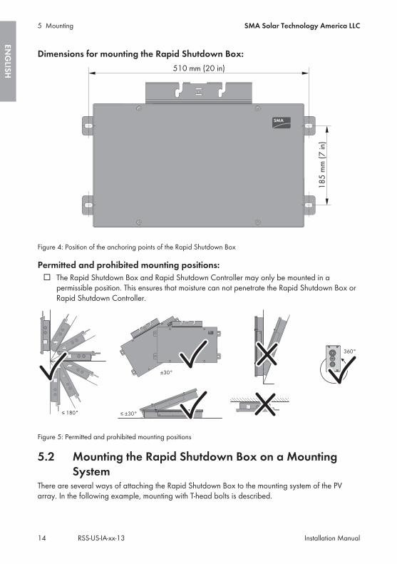
Dimensions for mounting the Rapid Shutdown Box:
Figure 4: Position of the anchoring points of the Rapid Shutdown Box
Permitted and prohibited mounting positions:☐ The Rapid Shutdown Box and Rapid Shutdown Controller may only be mounted in a
permissible position. This ensures that moisture can not penetrate the Rapid Shutdown Box orRapid Shutdown Controller.
Figure 5: Permitted and prohibited mounting positions
5.2 Mounting the Rapid Shutdown Box on a MountingSystem
There are several ways of attaching the Rapid Shutdown Box to the mounting system of the PVarray. In the following example, mounting with T-head bolts is described.
5 Mounting SMA Solar Technology America LLC
Installation ManualRSS-US-IA-xx-1314
ENG
LISH

Risk of falling when working on the roofThere is a risk of falling or slipping when working on the rooftop. Observe the applicableaccident prevention regulations for work on rooftops.
• Before stepping on the rooftop, ensure the load bearing capacity of all parts subjected toload.
• In accordance with the accident prevention regulations, a safety harness must be worn or asafety scaffold must be used.
• Use fall protection.
Damage to the PV module due to screws being too longThe length of the screws must be suitable for the distance between the Rapid Shutdown Box andthe underside of the PV module.
• Make sure that the PV module will not be damaged by the screws being used.
Additionally required mounting material (not included in the scope of delivery):☐ The required fastening material must be selected according to the mounting system used.☐ The mounting material must be made of stainless steel.☐ Diameter of the screws: maximum 8 mm (0.3 in)
Procedure:1. Insert the T-head bolts into the mounting system and turn by 90°. This will firmly anchor the
screws in the rack rail.2. Place the Rapid Shutdown Box onto the
anchored screws. Here, insert the screws into theoblong holes up to the desired fastening point.
5 MountingSMA Solar Technology America LLC
Installation Manual 15RSS-US-IA-xx-13
ENG
LISH
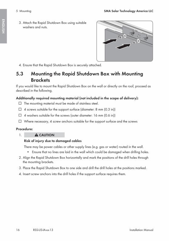
3. Attach the Rapid Shutdown Box using suitablewashers and nuts.
4. Ensure that the Rapid Shutdown Box is securely attached.
5.3 Mounting the Rapid Shutdown Box with MountingBrackets
If you would like to mount the Rapid Shutdown Box on the wall or directly on the roof, proceed asdescribed in the following.
Additionally required mounting material (not included in the scope of delivery):☐ The mounting material must be made of stainless steel.☐ 4 screws suitable for the support surface (diameter: 8 mm (0.3 in))☐ 4 washers suitable for the screws (outer diameter: 16 mm (0.6 in))☐ Where necessary, 4 screw anchors suitable for the support surface and the screws
Procedure:1.
Risk of injury due to damaged cablesThere may be power cables or other supply lines (e.g. gas or water) routed in the wall.
• Ensure that no lines are laid in the wall which could be damaged when drilling holes.2. Align the Rapid Shutdown Box horizontally and mark the positions of the drill holes through
the mounting brackets.3. Place the Rapid Shutdown Box to one side and drill the drill holes at the positions marked.4. Insert screw anchors into the drill holes if the support surface requires them.
5 Mounting SMA Solar Technology America LLC
Installation ManualRSS-US-IA-xx-1316
ENG
LISH
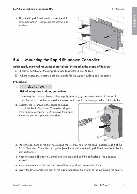
5. Align the Rapid Shutdown box over the drillholes and attach it using suitable screws andwashers.
5.4 Mounting the Rapid Shutdown ControllerAdditionally required mounting material (not included in the scope of delivery):
☐ 4 screws suitable for the support surface (diameter: 4 mm (0.16 in))☐ Where necessary, 4 screw anchors suitable for the support surface and the screws
Procedure:1.
Risk of injury due to damaged cablesThere may be power cables or other supply lines (e.g. gas or water) routed in the wall.
• Ensure that no lines are laid in the wall which could be damaged when drilling holes.2. Unscrew the 4 screws in the upper enclosure
part of the Rapid Shutdown Controller using across-head screwdriver (PZ 2), remove the upperenclosure part and place to one side.
3. Mark the positions of the drill holes using the 4 screw holes in the lower enclosure part of theRapid Shutdown Controller as a guide (see the rear side of the Rapid Shutdown Controller forhole distances).
4. Place the Rapid Shutdown Controller to one side and drill the drill holes at the positionsmarked.
5. Insert screw anchors into the drill holes if the support surface requires them.6. Screw the lower enclosure part of the Rapid Shutdown Controller to the wall using the screws.
5 MountingSMA Solar Technology America LLC
Installation Manual 17RSS-US-IA-xx-13
ENG
LISH

6 Electrical Connection
6.1 Safety during Electrical Connection
Damage to the Rapid Shutdown Box from moisture and dust ingress.Dust and moisture ingress can damage the Rapid Shutdown Box and impair its functionality.
• Do not open the Rapid Shutdown Box during rain, snow or high levels of humidity (> 95%).• Only use listed raintight or liquidtight conduit fittings to attach the conduits to the enclosure.
SMA recommends using conduit fittings with flat, pliable, thick rubber sealing gaskets. Thesealings should be roughly 2.54 mm (0.1 in / 7/64 in) in thickness. SMA recommendsagainst using thinner, harder sealings (typically yellow or green colored). These sealingtypes may not make reliable seals for this application. These sealings are approximately1.9 mm (0.075 in / 5/64 in) thick or less. SMA recommends against and does not acceptusing conduit fittings with round cross section and o-ring type sealings as these types ofseals are not reliable for this application.
• Seal all unused openings tightly.
Electrical installationsAll electrical installations must be carried out in accordance with the local standards and theNational Electrical Code® ANSI/NFPA 70 or the Canadian Electrical Code® CSA C22.1.
• The electrical connection of the Rapid Shutdown System may only be made by qualifiedpersons with appropriate skills.
• Ensure that no cables used for electrical connection are damaged.
The Rapid Shutdown function is only available if strings are correctly connected atthe inverter.The Rapid Shutdown function is not available if the strings from the Rapid Shutdown Box areconnected in parallel with any string from the PV array not connected through a RapidShutdown Box.
• Always connect the strings from the Rapid Shutdown Box to an inverter input with stringsfrom the same or other Rapid Shutdown Boxes.
• Do not connect the strings from a Rapid Shutdown Box in parallel with strings that donot connect through a Rapid Shutdown Box.
6 Electrical Connection SMA Solar Technology America LLC
Installation ManualRSS-US-IA-xx-1318
ENG
LISH
6.2 Overview of the Rapid Shutdown Box ConnectionArea
6.2.1 Exterior View
+
+
+
+
A
D
E
B
C
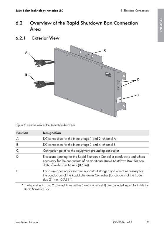
Figure 6: Exterior view of the Rapid Shutdown Box
Position DesignationA DC connection for the input strings 1 and 2, channel A
B DC connection for the input strings 3 and 4, channel B
C Connection point for the equipment grounding conductor
D Enclosure opening for the Rapid Shutdown Controller conductors and wherenecessary for the conductors of an additional Rapid Shutdown Box (for con-duits of trade size 16 mm (0.5 in))
E Enclosure opening for maximum 2 output strings* and where necessary forthe conductors of the Rapid Shutdown Controller (for conduits of the tradesize 21 mm (0.75 in))
* The input strings 1 and 2 (channel A) as well as 3 and 4 (channel B) are connected in parallel inside theRapid Shutdown Box.
6 Electrical ConnectionSMA Solar Technology America LLC
Installation Manual 19RSS-US-IA-xx-13
ENG
LISH

6.2.2 Interior View
Figure 7: Connection area inside the Rapid Shutdown Box
Position DesignationA Terminal block for the connection of the first output string, channel A
B Equipment Ground Bar
C Terminal block for the connection of the Rapid Shutdown Controller and/orfor the connection of an additional Rapid Shutdown Box
D Terminal block for the connection of the second output string, channel B
6.3 Connecting the Equipment Grounding Conductor tothe Rapid Shutdown Box
Each Rapid Shutdown Box can be grounded separately or several Rapid Shutdown Boxes can beconnected to one equipment grounding conductor. The required material for the connection of theequipment grounding conductor are included in the scope of delivery.
Additionally required material (not included in the scope of delivery):☐ Equipment grounding conductor
Equipment grounding conductor requirements:☐ Conductor type: copper wire☐ The conductor must be of solid wire.☐ Conductor cross-section: 4 mm² to 16 mm² (12 AWG to 6 AWG)
6 Electrical Connection SMA Solar Technology America LLC
Installation ManualRSS-US-IA-xx-1320
ENG
LISH
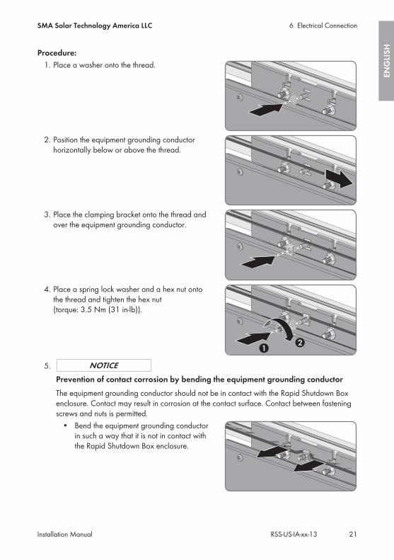
Procedure:1. Place a washer onto the thread.
2. Position the equipment grounding conductorhorizontally below or above the thread.
3. Place the clamping bracket onto the thread andover the equipment grounding conductor.
4. Place a spring lock washer and a hex nut ontothe thread and tighten the hex nut(torque: 3.5 Nm (31 in-lb)).
5.Prevention of contact corrosion by bending the equipment grounding conductorThe equipment grounding conductor should not be in contact with the Rapid Shutdown Boxenclosure. Contact may result in corrosion at the contact surface. Contact between fasteningscrews and nuts is permitted.
• Bend the equipment grounding conductorin such a way that it is not in contact withthe Rapid Shutdown Box enclosure.
6 Electrical ConnectionSMA Solar Technology America LLC
Installation Manual 21RSS-US-IA-xx-13
ENG
LISH
6.4 Connecting the Rapid Shutdown Box and RapidShutdown Controller Together
Additionally required material (not included in the scope of delivery):☐ Conduit: either a separate conduit (trade size: 16 mm (0.5 in) or smaller with suitable reducer
bush) or use the conduit of the output strings to lay the conductors.☐ If the conductors for the connection of the Rapid Shutdown Controller are to be laid in a
separate conduit: raintight or liquidtight conduit fitting (trade size: 16 mm (0.5 in) or smallerwith suitable reducer bush).
☐ When laying a tray cable for exposed run (TC-ER): use cable gland which is suitable for thecable and the enclosure opening.
Requirements for the conductors:☐ When laying in outdoor areas without conduit, a tray cable for exposed run (TC-ER) must be
used.☐ Conductor type: copper wire☐ Number of conductors: 5☐ If the conductors for the connection of the Rapid Shutdown Controller are laid in one conduit
together with the output strings, the conductors for the connection of the Rapid ShutdownController must be insulated for the maximum PV system voltage.
☐ The conductors must be made of solid wire, stranded wire or fine stranded wire. When usingfine stranded wire, bootlace ferrules must be used.
☐ Conductor cross section: 0.75 mm² to 1.5 mm² (18 AWG to 16 AWG)☐ Maximum length of the conductors from the Rapid Shutdown Box to the Rapid Shutdown
Controller: 50 m (164 ft)
Complying with the requirements for class 2 circuitsThe circuit of the Rapid Shutdown Controller meets all requirements for class 2 circuits. Themaximum open-circuit voltage is 20 V and maximum short-circuit current is 400 mA.
Information on laying tray cables for exposed run (TC-ER)The procedure for using conduits is described in this section. Instead of conduits, you can alsouse tray cables for exposed run (TC-ER).
• When using tray cables for exposed run (TC-ER), select suitable cable glands andattach to the enclosure opening instead of the conduit. When doing so, ensure that theenclosure opening is sealed and no moisture can enter.
Requirement:☐ All electrical installations must be carried out in accordance with the locally applicable
electrical standards and the National Electrical Code® ANSI/NFPA 70 or the CanadianElectrical Code® CSA C22.1.
6 Electrical Connection SMA Solar Technology America LLC
Installation ManualRSS-US-IA-xx-1322
ENG
LISH
Procedure:If several Rapid Shutdown Boxes are present in your Rapid Shutdown System, connect the firstRapid Shutdown Box to the Rapid Shutdown Controller first. To do so, first connect one end of theconductors to the Rapid Shutdown Box and then connect the other end of the conductors to theRapid Shutdown Controller.
• Connect the conductors to the Rapid Shutdown Box.• Connect the conductors to the Rapid Shutdown Controller.
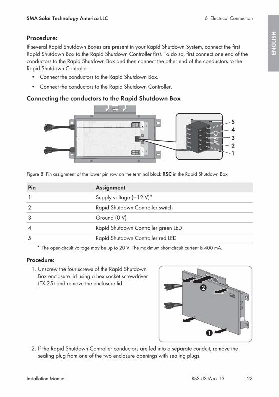
Connecting the conductors to the Rapid Shutdown Box
Figure 8: Pin assignment of the lower pin row on the terminal block RSC in the Rapid Shutdown Box
Pin Assignment1 Supply voltage (+12 V)*
2 Rapid Shutdown Controller switch
3 Ground (0 V)
4 Rapid Shutdown Controller green LED
5 Rapid Shutdown Controller red LED* The open-circuit voltage may be up to 20 V. The maximum short-circuit current is 400 mA.
Procedure:1. Unscrew the four screws of the Rapid Shutdown
Box enclosure lid using a hex socket screwdriver(TX 25) and remove the enclosure lid.
2. If the Rapid Shutdown Controller conductors are led into a separate conduit, remove thesealing plug from one of the two enclosure openings with sealing plugs.
6 Electrical ConnectionSMA Solar Technology America LLC
Installation Manual 23RSS-US-IA-xx-13
ENG
LISH

3. If the Rapid Shutdown Controller conductors are laid in the same conduit as the output strings,pull off the adhesive tape on the enclosure opening.
4. Insert the conduit fitting into the opening on the Rapid Shutdown Box and tighten from theinside using the counter nut.
5. Attach the conduit at the conduit fitting in the Rapid Shutdown Box enclosure.6. Lead the conductors up to the terminal block RSC in the Rapid Shutdown Box.7. Lead a silicone tube over the conductors inside
the Rapid Shutdown Box.
8. Strip off the conductor insulation by 8 mm (0.31 in).9. In the case of fine stranded wire, provide each conductor with a bootlace ferrule.
10. Connect the conductors to a five-pole plug.Observe the pin assignment.
11. Place the cable tie onto the silicone tube, tightenand cut off the projecting end of the cable tie.This connects the conductors and the siliconetube together securely.
12. Plug the five-pole plug with the connectedconductors into the lower pin row of the terminalblock RSC.
13. If there is only one Rapid Shutdown Box in thesystem, plug the second five-pole plug into theupper row of the terminal block RSC and placea jumper wire between pins 3 and 4. Here, usea jumper wire that is rated for the maximumsystem voltages or insulate the jumper wire usinga piece of one of the supplied silicone tubes.
6 Electrical Connection SMA Solar Technology America LLC
Installation ManualRSS-US-IA-xx-1324
ENG
LISH

Connecting the conductors to the Rapid Shutdown Controller
+
A −
− B
+R
SC
NC
12
X12
X
X12
X
NC
12
X12
X
X12
X
12345
Figure 9: Overview of the terminal blocks in the Rapid Shutdown Controller
Pin of the connectingterminal plate in theRapid ShutdownBox
Terminal in theRapid ShutdownController
Assignment
1 X2 Supply voltage (+12 V)*
2 2 Rapid Shutdown Controller switch
3 NC 1 Ground (0 V)
4 X1 Rapid Shutdown Controller green LED
5 X1 Rapid Shutdown Controller red LED* You can select on which terminal the connection is to be made, because a bridge must be placed
between the connections later.
Information on laying tray cables for exposed run (TC-ER)The procedure for using conduits is described in this section. Instead of conduits, you can alsouse tray cables for exposed run (TC-ER).
• When using tray cables for exposed run (TC-ER), select suitable cable glands andattach to the enclosure opening instead of the conduit. When doing so, ensure that theenclosure opening is sealed and no moisture can enter.
6 Electrical ConnectionSMA Solar Technology America LLC
Installation Manual 25RSS-US-IA-xx-13
ENG
LISH

Procedure:1. Break out the desired knockout on the Rapid
Shutdown Controller using a hammer and ascrewdriver When doing so, note that whenusing the knockouts above and below in thelower enclosure part, that the supplied adaptermust be used for conduits of the trade size16 mm (0.5 in).
2. Where necessary, insert the supplied adapter in the position knocked out on the RapidShutdown Controller and tighten from the inside using the counter nut.
3. Attach the conduit to the conduit fitting or onto the adapter in the Rapid Shutdown Controllerenclosure.
4. Lead the conductors up to the terminal blocks in the Rapid Shutdown Controller.5. Strip off the conductor insulation by 8 mm (0.31 in).6. In the case of fine stranded wire, provide each conductor with a bootlace ferrule.7. Connect the conductors to the terminal blocks in
accordance with the assignment. To do so, inserteach conductor into the corresponding terminaland tighten the screw on the terminal using across-head screwdriver (PZ 2).
8. Place a jumper wire between the terminal X2 of the green LED and terminal X2 of the redLED.
9. Ensure that all terminals are allocated to the correct conductors.10. Ensure that the conductors are plugged completely into the terminals up to their insulation.
Useful hint: To release the conductors from the terminals, the terminals must be opened. To doso, loosen the screw on the terminal using a cross-head screwdriver (PZ 2).
6 Electrical Connection SMA Solar Technology America LLC
Installation ManualRSS-US-IA-xx-1326
ENG
LISH
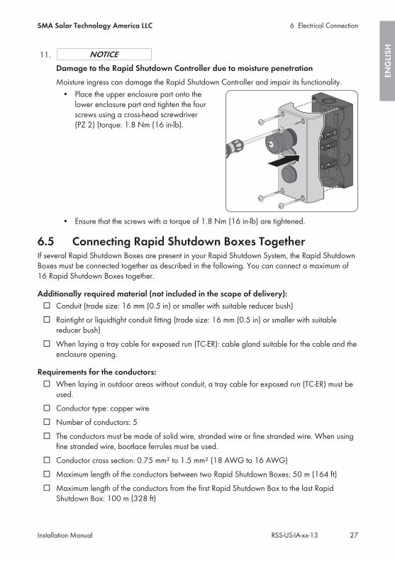
11.Damage to the Rapid Shutdown Controller due to moisture penetrationMoisture ingress can damage the Rapid Shutdown Controller and impair its functionality.
• Place the upper enclosure part onto thelower enclosure part and tighten the fourscrews using a cross-head screwdriver(PZ 2) (torque: 1.8 Nm (16 in-lb).
• Ensure that the screws with a torque of 1.8 Nm (16 in-lb) are tightened.
6.5 Connecting Rapid Shutdown Boxes TogetherIf several Rapid Shutdown Boxes are present in your Rapid Shutdown System, the Rapid ShutdownBoxes must be connected together as described in the following. You can connect a maximum of16 Rapid Shutdown Boxes together.
Additionally required material (not included in the scope of delivery):☐ Conduit (trade size: 16 mm (0.5 in) or smaller with suitable reducer bush)☐ Raintight or liquidtight conduit fitting (trade size: 16 mm (0.5 in) or smaller with suitable
reducer bush)☐ When laying a tray cable for exposed run (TC-ER): cable gland suitable for the cable and the
enclosure opening.
Requirements for the conductors:☐ When laying in outdoor areas without conduit, a tray cable for exposed run (TC-ER) must be
used.☐ Conductor type: copper wire☐ Number of conductors: 5☐ The conductors must be made of solid wire, stranded wire or fine stranded wire. When using
fine stranded wire, bootlace ferrules must be used.☐ Conductor cross section: 0.75 mm² to 1.5 mm² (18 AWG to 16 AWG)☐ Maximum length of the conductors between two Rapid Shutdown Boxes: 50 m (164 ft)☐ Maximum length of the conductors from the first Rapid Shutdown Box to the last Rapid
Shutdown Box: 100 m (328 ft)
6 Electrical ConnectionSMA Solar Technology America LLC
Installation Manual 27RSS-US-IA-xx-13
ENG
LISH
Information on laying tray cables for exposed run (TC-ER)The procedure for using conduits is described in this section. Instead of conduits, you can alsouse tray cables for exposed run (TC-ER).
• When using tray cables for exposed run (TC-ER), select suitable cable glands andattach to the enclosure opening instead of the conduit. When doing so, ensure that theenclosure opening is sealed and no moisture can enter.
Requirement:☐ All electrical installations must be carried out in accordance with the locally applicable
electrical standards and the National Electrical Code® ANSI/NFPA 70 or the CanadianElectrical Code® CSA C22.1.
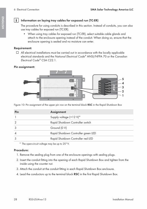
Pin assignment:
Figure 10: Pin assignment of the upper pin row on the terminal block RSC in the Rapid Shutdown Box
Pin Assignment1 Supply voltage (+12 V)*
2 Rapid Shutdown Controller switch
3 Ground (0 V)
4 Rapid Shutdown Controller green LED
5 Rapid Shutdown Controller red LED* The open-circuit voltage may be up to 20°V.
Procedure:1. Remove the sealing plug from one of the enclosure openings with sealing plugs.2. Insert the conduit fitting into the opening of each Rapid Shutdown Box and tighten from the
inside using the counter nut.3. Attach the conduit at the conduit fitting in each Rapid Shutdown Box enclosure.4. Lead the conductors up to the terminal block RSC in the first Rapid Shutdown Box.
6 Electrical Connection SMA Solar Technology America LLC
Installation ManualRSS-US-IA-xx-1328
ENG
LISH
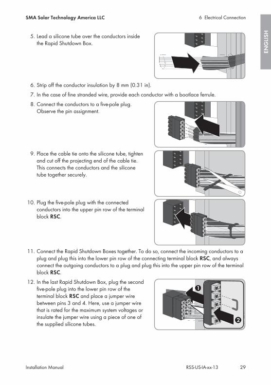
5. Lead a silicone tube over the conductors insidethe Rapid Shutdown Box.
6. Strip off the conductor insulation by 8 mm (0.31 in).7. In the case of fine stranded wire, provide each conductor with a bootlace ferrule.8. Connect the conductors to a five-pole plug.
Observe the pin assignment.
9. Place the cable tie onto the silicone tube, tightenand cut off the projecting end of the cable tie.This connects the conductors and the siliconetube together securely.
10. Plug the five-pole plug with the connectedconductors into the upper pin row of the terminalblock RSC.
11. Connect the Rapid Shutdown Boxes together. To do so, connect the incoming conductors to aplug and plug this into the lower pin row of the connecting terminal block RSC, and alwaysconnect the outgoing conductors to a plug and plug this into the upper pin row of the terminalblock RSC.
12. In the last Rapid Shutdown Box, plug the secondfive-pole plug into the lower pin row of theterminal block RSC and place a jumper wirebetween pins 3 and 4. Here, use a jumper wirethat is rated for the maximum system voltages orinsulate the jumper wire using a piece of one ofthe supplied silicone tubes.
6 Electrical ConnectionSMA Solar Technology America LLC
Installation Manual 29RSS-US-IA-xx-13
ENG
LISH

6.6 Connecting the Strings to Rapid Shutdown BoxUp to four input strings and two output strings can be connected to the Rapid Shutdown Box. In theRapid Shutdown Box, two of the four input strings are connected in parallel. The input strings mustbe connected to the DC conductors fitted with MC4 connectors that lead from the Rapid ShutdownBox. The output strings must be connected to the corresponding terminal blocks inside the RapidShutdown Box.
Faulty operation of the inverter due to incorrect connection of the output strings tothe Rapid Shutdown BoxThe output strings must lead to the same inverter if two output strings are connected to theRapid Shutdown Box. The operation of at least one inverter is interrupted if the two outputstrings are connected to different inverters.
• Connect only output strings to the connecting terminal plate A and B which are leadingto the same inverter.
Procedure:• Connect the output strings.• Connect the input strings.
Connecting the output strings
Additionally required material:☐ Conduit (trade size: 21 mm (0.75 in) or smaller with suitable reducer bush)☐ Raintight or liquidtight conduit fitting (trade size: 21 mm (0.75 in) or smaller with suitable
reducer bush)
Requirements for the conductors:☐ The conductors must be made of solid wire, stranded wire or fine stranded wire. When using
fine stranded wire, bootlace ferrules must be used.☐ Conductor cross-section: 4 mm² to 10 mm² (12 AWG to 6 AWG)
Procedure:1.
Danger to life due to high voltages of the PV arrayWhen exposed to sunlight, the PV array generates dangerous DC voltage which is present inthe DC conductors. Touching the DC conductors can lead to lethal electric shocks.
• Switch off the DC load-break switch on the inverter.• Only touch the DC conductors on their insulation.
2. Pull off the adhesive tape on the enclosure opening.3. Attach the conduit at the conduit fitting in the Rapid Shutdown Box enclosure.4. Lead the positive and negative conductors of the first output string up to the connecting
terminal plate A.
6 Electrical Connection SMA Solar Technology America LLC
Installation ManualRSS-US-IA-xx-1330
ENG
LISH
5. Lead the positive and negative conductors of the second output string up to the connectingterminal plate B.
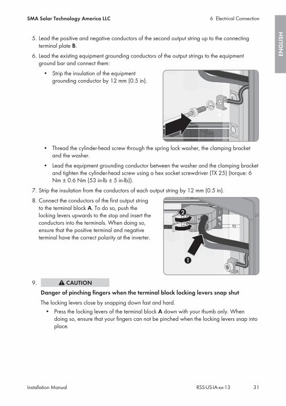
6. Lead the existing equipment grounding conductors of the output strings to the equipmentground bar and connect them:
• Strip the insulation of the equipmentgrounding conductor by 12 mm (0.5 in).
• Thread the cylinder-head screw through the spring lock washer, the clamping bracketand the washer.
• Lead the equipment grounding conductor between the washer and the clamping bracketand tighten the cylinder-head screw using a hex socket screwdriver (TX 25) (torque: 6Nm ± 0.6 Nm (53 in-lb ± 5 in-lb)).
7. Strip the insulation from the conductors of each output string by 12 mm (0.5 in).8. Connect the conductors of the first output string
to the terminal block A. To do so, push thelocking levers upwards to the stop and insert theconductors into the terminals. When doing so,ensure that the positive terminal and negativeterminal have the correct polarity at the inverter.
9.Danger of pinching fingers when the terminal block locking levers snap shutThe locking levers close by snapping down fast and hard.
• Press the locking levers of the terminal block A down with your thumb only. Whendoing so, ensure that your fingers can not be pinched when the locking levers snap intoplace.
6 Electrical ConnectionSMA Solar Technology America LLC
Installation Manual 31RSS-US-IA-xx-13
ENG
LISH
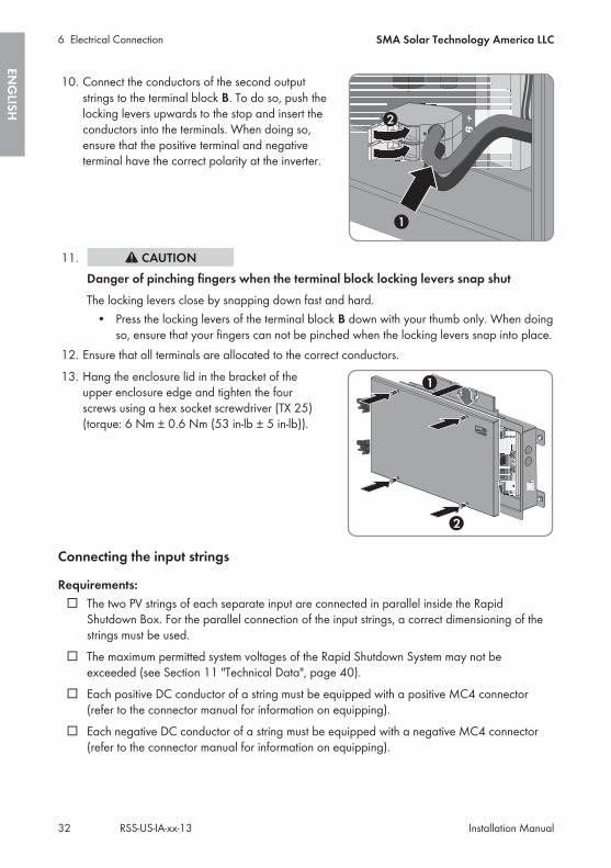
10. Connect the conductors of the second outputstrings to the terminal block B. To do so, push thelocking levers upwards to the stop and insert theconductors into the terminals. When doing so,ensure that the positive terminal and negativeterminal have the correct polarity at the inverter.
11.Danger of pinching fingers when the terminal block locking levers snap shutThe locking levers close by snapping down fast and hard.
• Press the locking levers of the terminal block B down with your thumb only. When doingso, ensure that your fingers can not be pinched when the locking levers snap into place.
12. Ensure that all terminals are allocated to the correct conductors.13. Hang the enclosure lid in the bracket of the
upper enclosure edge and tighten the fourscrews using a hex socket screwdriver (TX 25)(torque: 6 Nm ± 0.6 Nm (53 in-lb ± 5 in-lb)).
Connecting the input strings
Requirements:☐ The two PV strings of each separate input are connected in parallel inside the Rapid
Shutdown Box. For the parallel connection of the input strings, a correct dimensioning of thestrings must be used.
☐ The maximum permitted system voltages of the Rapid Shutdown System may not beexceeded (see Section 11 "Technical Data", page 40).
☐ Each positive DC conductor of a string must be equipped with a positive MC4 connector(refer to the connector manual for information on equipping).
☐ Each negative DC conductor of a string must be equipped with a negative MC4 connector(refer to the connector manual for information on equipping).
6 Electrical Connection SMA Solar Technology America LLC
Installation ManualRSS-US-IA-xx-1332
ENG
LISH
Procedure:1.
Danger to life due to high voltagesWhen exposed to sunlight, the PV array generates dangerous DC voltage which is present inthe DC conductors. Touching the DC conductors can lead to lethal electric shocks.
• Ensure that no voltage is present on the input strings.• Ensure that the Rapid Shutdown Box is closed.
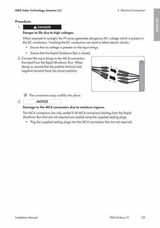
2. Connect the input strings to the MC4 connectorsthat lead from the Rapid Shutdown Box. Whendoing so, ensure that the positive terminal andnegative terminal have the correct polarity.
☑ The connectors snap audibly into place.
3.Damage to the MC4 connectors due to moisture ingress.The MC4 connectors are only sealed if all MC4 connectors leading from the RapidShutdown Box that are not required are sealed using the supplied sealing plugs.
• Plug the supplied sealing plugs into the MC4 connectors that are not required.
6 Electrical ConnectionSMA Solar Technology America LLC
Installation Manual 33RSS-US-IA-xx-13
ENG
LISH
7 Commissioning the Rapid Shutdown System1. Commission all inverters in the system (see inverter manual).2. Check whether the inverter to which the strings of the Rapid Shutdown Box are connected
starts feed-in operation.If the inverters display no errors and start feed-in operation, the Rapid Shutdown System isconnected correctly and automatically commissioned.If the inverters do not start feed-in operation despite sufficient irradiation and display an error,it is likely that an installation error is present. Ensure that the Rapid Shutdown System isinstalled correctly.
3. If the Rapid Shutdown System has been commissioned, check the function of the RapidShutdown System (see Section 8, page 35).
7 Commissioning the Rapid Shutdown System SMA Solar Technology America LLC
Installation ManualRSS-US-IA-xx-1334
ENG
LISH
8 Checking the Function of the Rapid Shutdown SystemThe Rapid Shutdown System is supplied via the PV array. If there is insufficient irradiation on the PVarray, the supply voltage of the Rapid Shutdown System is too low and the function of the RapidShutdown System is not able to be checked.
Requirement:☐ The Rapid Shutdown System must be commissioned.☐ There must be sufficient irradiation on the PV array.
Procedure:1. Press the emergency switch on the Rapid Shutdown Controller. This starts the automatic self-test
of the Rapid Shutdown Box and activates the Rapid Shutdown System.☑ The red LED on the Rapid Shutdown Controller lights briefly or flashes. The Rapid
Shutdown Box reduces the voltage on the output string side. As soon as the voltage iswithin the permitted range, the green LED on the Rapid Shutdown Controller glowsconstantly.
☑ The green LED on the Rapid Shutdown Controller glows constantly. The Rapid ShutdownSystem is active and the voltages on the output string side of the Rapid Shutdown Boxare ≤30 V.
✖ None of the LEDs on the Rapid Shutdown Controller are glowing?Several causes are possible: Either the irradiation on the PV array is too low and, thus,the supply voltage of the Rapid Shutdown System insufficient or the installation of theRapid Shutdown System is faulty or the Rapid Shutdown Box is defective.
• Make sure that the supply voltage of the Rapid Shutdown System is sufficient.• Ensure that the Rapid Shutdown System is installed correctly.• When the Rapid Shutdown System has enough supply voltage and is installed
correctly and still none of the LEDs are glowing, the Rapid Shutdown Box is faultyand must be replaced. Contact the Service (see Section 12 "Contact", page 42).
✖ The red LED on the Rapid Shutdown Controller glows constantly?The Rapid Shutdown Box is defective and the Rapid Shutdown System is not active.
• Contact the Service (see Section 12 "Contact", page 42).2. Reset the Rapid Shutdown function (see Section 9.2, page 36).
8 Checking the Function of the Rapid Shutdown SystemSMA Solar Technology America LLC
Installation Manual 35RSS-US-IA-xx-13
ENG
LISH
9 Operating the Rapid Shutdown Controller
9.1 Triggering the Rapid Shutdown Function• Press the emergency switch on the Rapid Shutdown Controller.☑ The red LED on the Rapid Shutdown Controller lights briefly or flashes. The Rapid Shutdown
Box reduces the voltage on the output string side. As soon as the voltage is within thepermitted range, the green LED on the Rapid Shutdown Controller glows constantly.
☑ The green LED on the Rapid Shutdown Controller glows constantly. The Rapid ShutdownSystem is active and the voltages on the output string side of the Rapid Shutdown Box are≤30 V.
✖ None of the LEDs on the Rapid Shutdown Controller are glowing?Several causes are possible: Either the irradiation on the PV array is too low and, thus, thesupply voltage of the Rapid Shutdown System insufficient or the installation of the RapidShutdown System is faulty or the Rapid Shutdown Box is defective.
• Make sure that the supply voltage of the Rapid Shutdown System is sufficient.• Ensure that the Rapid Shutdown System is installed correctly.• When the Rapid Shutdown System has enough supply voltage and is installed correctly
and still none of the LEDs are glowing, the Rapid Shutdown Box is faulty and must bereplaced. Contact the Service (see Section 12 "Contact", page 42).
✖ The red LED on the Rapid Shutdown Controller glows constantly?The Rapid Shutdown Box is defective and the Rapid Shutdown System is not active.
• Contact the Service (see Section 12 "Contact", page 42).
9.2 Resetting the Rapid Shutdown Function1. Ensure that the PV system can be reset to operating mode.2. Insert the key into the keyhole of the emergency switch on the Rapid Shutdown Controller and
turn the key clockwise.If the key for resetting the Rapid Shutdown Function is lost, contact the Service and request anew key.
☑ The emergency switch returns to its starting position.3. Remove the key from the keyhole and store safely in a location accessible to the PV system
operator.
9 Operating the Rapid Shutdown Controller SMA Solar Technology America LLC
Installation ManualRSS-US-IA-xx-1336
ENG
LISH
10 Decommissioning the Rapid Shutdown SystemProcedure:
1.Danger to life due to high voltages of the PV arrayWhen exposed to sunlight, the PV array generates dangerous DC voltage which is present inthe DC conductors. Touching the DC conductors can lead to lethal electric shocks.
• Switch off the DC load-break switch on the inverter.• Disconnect the DC connectors on the input strings.• Only touch the DC conductors on their insulation.
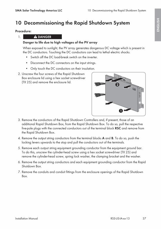
2. Unscrew the four screws of the Rapid ShutdownBox enclosure lid using a hex socket screwdriver(TX 25) and remove the enclosure lid.
3. Remove the conductors of the Rapid Shutdown Controllers and, if present, those of anadditional Rapid Shutdown Box, from the Rapid Shutdown Box. To do so, pull the respectivefive-pole plugs with the connected conductors out of the terminal block RSC and remove fromthe Rapid Shutdown Box.
4. Remove the output string conductors from the terminal blocks A and B. To do so, push thelocking levers upwards to the stop and pull the conductors out of the terminals.
5. Remove each output string equipment grounding conductor from the equipment ground bar.To do this, unscrew the cylinder-head screw using a hex socket screwdriver (TX 25) andremove the cylinder-head screw, spring lock washer, the clamping bracket and the washer.
6. Remove the output string conductors and each equipment grounding conductor from the RapidShutdown Box.
7. Remove the conduits and conduit fittings from the enclosure openings of the Rapid ShutdownBox.
10 Decommissioning the Rapid Shutdown SystemSMA Solar Technology America LLC
Installation Manual 37RSS-US-IA-xx-13
ENG
LISH
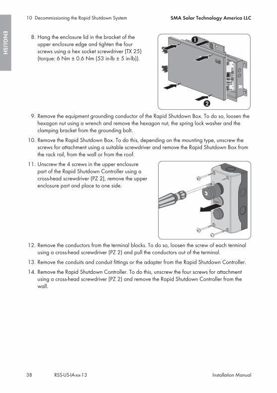
8. Hang the enclosure lid in the bracket of theupper enclosure edge and tighten the fourscrews using a hex socket screwdriver (TX 25)(torque: 6 Nm ± 0.6 Nm (53 in-lb ± 5 in-lb)).
9. Remove the equipment grounding conductor of the Rapid Shutdown Box. To do so, loosen thehexagon nut using a wrench and remove the hexagon nut, the spring lock washer and theclamping bracket from the grounding bolt.
10. Remove the Rapid Shutdown Box. To do this, depending on the mounting type, unscrew thescrews for attachment using a suitable screwdriver and remove the Rapid Shutdown Box fromthe rack rail, from the wall or from the roof.
11. Unscrew the 4 screws in the upper enclosurepart of the Rapid Shutdown Controller using across-head screwdriver (PZ 2), remove the upperenclosure part and place to one side.
12. Remove the conductors from the terminal blocks. To do so, loosen the screw of each terminalusing a cross-head screwdriver (PZ 2) and pull the conductors out of the terminal.
13. Remove the conduits and conduit fittings or the adapter from the Rapid Shutdown Controller.14. Remove the Rapid Shutdown Controller. To do this, unscrew the four screws for attachment
using a cross-head screwdriver (PZ 2) and remove the Rapid Shutdown Controller from thewall.
10 Decommissioning the Rapid Shutdown System SMA Solar Technology America LLC
Installation ManualRSS-US-IA-xx-1338
ENG
LISH
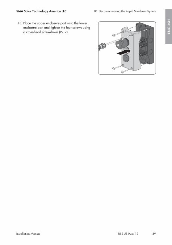
15. Place the upper enclosure part onto the lowerenclosure part and tighten the four screws usinga cross-head screwdriver (PZ 2).
10 Decommissioning the Rapid Shutdown SystemSMA Solar Technology America LLC
Installation Manual 39RSS-US-IA-xx-13
ENG
LISH

11 Technical Data
11.1 Rapid Shutdown BoxMaximum input voltage 600 V
Input voltage range 110 V to 600 V
Nominal current per channel 20 A
Maximum input short-circuit current per channel 36 A
Width x height x depth, without input stringssticking out of the Rapid Shutdown Box
542 mm x 340 mm x 75 mm(21.3 in x 13.4 in x 3 in)
Length x width x height of the packaging 770 mm x 395 mm x 125 mm(30.3 in x 15.5 in x 4.9 in)
Weight of the Rapid Shutdown Box, withoutpackaging
3.8 kg (8.4 lb)
Weight of the Rapid Shutdown Box, includingpackaging
5.5 kg (12.1 lb)
Operating temperature range -40°C to +75°C(-40°F to +167°F)
Maximum permissible value for relative humid-ity, condensing
4% to 100%
Maximum operating altitude above mean sealevel (MSL)
3000 m (9843 ft)
Enclosure degree of protection according toUL 50
4X
Torque of the enclosure lid screws 6 Nm ± 0.6 Nm (53 in-lb ± 5 in-lb)
11.2 Rapid Shutdown ControllerWidth x height x depth, without input strings 80 mm x 153 mm x 104 mm
(3.15 in x 6.02 in x 4.1 in)
Weight, without packaging 328 g (0.72 lb)
Operating temperature range -25°C to +70°C(-13°F to +158°F)
Maximum operating altitude above mean sealevel (MSL)
3000 m (9843 ft)
11 Technical Data SMA Solar Technology America LLC
Installation ManualRSS-US-IA-xx-1340
ENG
LISH
Enclosure degree of protection according toUL 50
4X
Torque of the upper enclosure lid screws 1.8 Nm (16 in-lb)
11 Technical DataSMA Solar Technology America LLC
Installation Manual 41RSS-US-IA-xx-13
ENG
LISH
12 ContactIf you have technical problems with our products, please contact the SMA Service Line. We requirethe following information in order to provide you with the necessary assistance:
• Serial number of the Rapid Shutdown Box• Serial number of the Rapid Shutdown Controller
UnitedStates/ Esta-dos Unidos
SMA Solar TechnologyAmerica LLCRocklin, CA
Toll free for USA, Canada and Puerto Rico / Llamada gra-tuita en EE. UU., Canadá y Puerto Rico:+1 877-MY-SMATech (+1 877-697-6283)International / Internacional: +1 916 625-0870
Canada/Canadá
SMA Solar TechnologyCanada Inc.Mississauga
Toll free for Canada / gratuit pour le Canada:+1 877-MY-SMATech (+1 877-697-6283)
12 Contact SMA Solar Technology America LLC
Installation ManualRSS-US-IA-xx-1342
ENG
LISH
13 Compliance InformationFCC ComplianceThis device complies with Part 15 of the FCC Rules. Operation is subject to the following conditions:
1. This device may not cause harmful interference, and2. This device must accept any interference received, including interference that may cause
undesired operation.NOTE: This equipment has been tested and found to comply with the limits for a Class B digitaldevice, pursuant to Part 15 of the FCC Rules. These limits are designed to provide reasonableprotection against harmful interference in a residential installation. This equipment generates, uses,and can radiate radio frequency energy and if not installed and used in accordance with theinstructions, may cause harmful interference to radio communications. However, there is noguarantee that interference will not occur in a particular installation. If this equipment does causeharmful interference to radio or television reception, which can be determined by turning theequipment off and on, the user is encouraged to try to correct the interference by one or more ofthe following measures:
• Reorient or relocate the receiving antenna.• Increase the separation between the equipment and the receiver.• Connect the equipment into an outlet on a circuit different from that to which the receiver is
connected.• Consult the dealer or an experienced radio/TV technician for help.
The user is cautioned that changes or modifications not expressly approved by SMA SolarTechnology America LLC could void the user’s authority to operate this equipment.
IC ComplianceThis Class B digital apparatus complies with Canadian ICES-003.Cet appareil numérique de la classe B est conforme à la norme NMB-003 du Canada.
13 Compliance InformationSMA Solar Technology America LLC
Installation Manual 43RSS-US-IA-xx-13
ENG
LISH

Disposiciones legalesCopyright © 2016 SMA Solar Technology America LLC. Reservados todos los derechos.Queda prohibida la reproducción total o parcial de este documento, así como su almacenamientoen un sistema de recuperación y toda transmisión electrónica, mecánica, fotográfica, magnética ode otra índole sin previa autorización por escrito de SMA Solar Technology America, LLC.Ni SMA Solar Technology America, LLC ni SMA Solar Technology Canada Inc. establecenrepresentaciones, ni expresas ni implícitas, con respecto a estas instrucciones o a cualquiera de losequipos o softwares aquí descritos, incluyendo (sin limitación) cualquier garantía implícita encuanto a utilidad, mercantilidad o aptitud para cualquier propósito particular. Tales garantíasquedan expresamente denegadas. Ni SMA Solar Technology America, LLC ni sus distribuidores ovendedores, ni SMA Solar Technology Canada Inc. ni sus distribuidores o vendedores seránresponsables por ningún daño indirecto, incidental o resultante, bajo ninguna circunstancia.La exclusión de garantías implícitas puede no ser aplicable en todos los casos según algunosestatutos, y por tanto la exclusión mencionada anteriormente puede no ser aplicable.Las especificaciones están sujetas a cambios sin previo aviso. Se ha tratado por todos los mediosde hacer que este documento sea completo y preciso y esté actualizado. Sin embargo, advertimosa los lectores que SMA Solar Technology America, LLC y SMA Solar Technology Canada Inc. sereservan el derecho de cambiar estas especificaciones sin previo aviso o conforme con lascondiciones del existente contrato de entrega si lo consideran adecuado para optimizar elproducto y su uso. SMA no será responsable por ningún daño, ya sea indirecto, incidental oresultante, como consecuencia de confiar en el material que se presenta, incluyendo, aunque noexclusivamente, omisiones, errores tipográficos, aritméticos o de listado en el material delcontenido.
Marcas registradasSe reconocen todas las marcas registradas, incluso si no están señaladas por separado. La faltade señalización no implica que la mercancía o las marcas sean libres.Modbus® es una marca registrada de Schneider Electric y cuenta con licencia de laModbus Organization, Inc.QR Code es una marca registrada de DENSO WAVE INCORPORATED.Phillips® y Pozidriv® son marcas registradas de Phillips Screw Company.Torx® es una marca registrada de Acument Global Technologies, Inc.
SMA Solar Technology America LLC6020 West Oaks Blvd.
Suite 300 Rocklin, CA 95765 U.S.A.SMA Solar Technology Canada Inc.
2425 Matheson Blvd. E7th Floor
Mississauga, ON L4W 5K4Canadá
Disposiciones legales SMA Solar Technology America LLC
Instrucciones de instalaciónRSS-US-IA-xx-1344
ESPAÑ
OL
Instrucciones de seguridad importantesCONSERVAR INSTRUCCIONESEstas instrucciones contienen información importante para estos productos:
• RSB-2S-US-10 (SMA Rapid Shutdown Box)• RSC-1X-US-10 (SMA Rapid Shutdown Controller)
Las indicaciones de estas instrucciones deben cumplirse durante el manejo con el producto.
El producto ha sido diseñado y probado conforme a los requisitos internacionales de seguridad,sin embargo, como en todos los equipos eléctricos o electrónicos, durante la instalación y elfuncionamiento deben tomarse determinadas medidas de precaución. Lea y cumpla todas lasindicaciones y advertencias de seguridad de estas instrucciones para minimizar el riesgo delesiones al usuario y garantizar una instalación y un funcionamiento seguros del producto.
Advertencias en este documentoUna advertencia describe un peligro que puede causar lesiones al usuario o daños materiales.Llama la atención sobre un procedimiento o una actividad que, de no realizarse correctamente,puede causar lesiones al usuario o daños materiales en productos de SMA o productosconectados a estos.
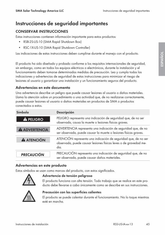
Símbolo DescripciónPELIGRO representa una indicación de seguridad que, de no serobservada, causa la muerte o lesiones físicas graves.
ADVERTENCIA representa una indicación de seguridad que, de noser observada, puede causar la muerte o lesiones físicas graves.
ATENCIÓN representa una indicación de seguridad que, de no serobservada, puede causar lesiones físicas leves o de gravedad me-dia.
PRECAUCIÓN representa una indicación de seguridad que, de noser observada, puede causar daños materiales.
Advertencias en este productoEstos símbolos se usan como marcas del producto, con estos significados.
Advertencia de tensión peligrosaEl producto funciona con alta tensión. Todo trabajo que se realice en este pro-ducto debe llevarse a cabo únicamente como se describe en sus instrucciones.
Precaución con las superficies calientesEl producto se puede calentar durante el funcionamiento. No lo toque mientrasesté en marcha.
Instrucciones de seguridad importantesSMA Solar Technology America LLC
Instrucciones de instalación 45RSS-US-IA-xx-13
ESPA
ÑO
L
Observar las instrucciones de usoLea la documentación del producto antes de trabajar con él. Siga todas lasprecauciones e instrucciones como se describen en la documentación.
Indicaciones generales
Todas las instalaciones eléctricas deben realizarse conforme a la normativa local vigente y alcódigo National Electrical Code® ANSI/NFPA 70 o al Canadian Electrical Code® CSA C22.1.Este documento no sustituye en ningún caso, ni tiene la pretensión de hacerlo, a cualquierlegislación, reglamento o norma regional, federal, provincial o estatal aplicables a la instalacióny el uso del producto; en especial, a las normas vigentes relativas a la seguridad eléctrica. Lainstalación debe llevarse a cabo de conformidad con la legislación, las disposiciones, losreglamentos y las normas vigentes en el lugar. SMA no asume responsabilidad alguna relativa alcumplimiento o al incumplimiento de la legislación o las disposiciones relacionadas con lainstalación del producto. El producto no contiene ningún componente sobre el que el usuario deba realizar labores demantenimiento. Para realizar cualquier trabajo de reparación y mantenimiento, el equipo debe enviarse siemprea un centro técnico aprobado por SMA. Antes de la instalación y el manejo del producto, lea todas las indicaciones y advertencias deestas instrucciones. El cableado del producto solo puede llevarlo a cabo un especialista.
Indicaciones generales SMA Solar Technology America LLC
Instrucciones de instalaciónRSS-US-IA-xx-1346
ESPAÑ
OL

Índice1 Indicaciones sobre este documento ....................................... 49
1.1 Área de validez ................................................................................. 491.2 Grupo de destinatarios ..................................................................... 491.3 Símbolos............................................................................................. 491.4 Nomenclatura.................................................................................... 49
2 Seguridad ................................................................................. 502.1 Uso previsto ....................................................................................... 502.2 Indicaciones de seguridad................................................................ 51
3 Contenido de la entrega.......................................................... 52
4 Descripción del producto......................................................... 534.1 Rapid Shutdown System.................................................................... 53
5 Montaje..................................................................................... 555.1 Requisitos para el montaje................................................................ 555.2 Montaje de la Rapid Shutdown Box con carril de perfil ................ 565.3 Montaje de la Rapid Shutdown Box con bridas de sujeción ......... 585.4 Montaje del Rapid Shutdown Controller ......................................... 59
6 Conexión eléctrica.................................................................... 606.1 Seguridad en la conexión eléctrica ................................................. 606.2 Vista general de las áreas de conexión de la Rapid Shutdown
Box ..................................................................................................... 616.2.1 Vista exterior................................................................................ 616.2.2 Vista interior................................................................................. 62
6.3 Conexión del conductor de puesta a tierra del equipo a la RapidShutdown Box.................................................................................... 62
6.4 Conexión entre sí de Rapid Shutdown Box y Rapid ShutdownController ........................................................................................... 64
6.5 Conexión entre sí de las Rapid Shutdown Box ............................... 696.6 Conexión de los strings a la Rapid Shutdown Box ......................... 72
7 Puesta en marcha del Rapid Shutdown System.................... 76
ÍndiceSMA Solar Technology America LLC
Instrucciones de instalación 47RSS-US-IA-xx-13
ESPA
ÑO
L

8 Comprobación del correcto funcionamiento del RapidShutdown System..................................................................... 77
9 Manejo del Rapid Shutdown Controller ................................ 789.1 Activación de la función Rapid Shutdown....................................... 789.2 Restablecimiento de la función Rapid Shutdown ............................ 78
10 Puesta fuera de servicio del Rapid Shutdown System.......... 79
11 Datos técnicos........................................................................... 8211.1 Rapid Shutdown Box......................................................................... 8211.2 Rapid Shutdown Controller............................................................... 82
12 Contacto .................................................................................... 84
13 Información de cumplimiento ................................................. 85
Índice SMA Solar Technology America LLC
Instrucciones de instalaciónRSS-US-IA-xx-1348
ESPAÑ
OL
1 Indicaciones sobre este documento
1.1 Área de validezEste documento es aplicable a estos modelos:
• RSB-2S-US-10 (SMA Rapid Shutdown Box)• RSC-1X-US-10 (SMA Rapid Shutdown Controller)
1.2 Grupo de destinatariosLas actividades descritas en este documento deben realizarlas exclusivamente especialistas quehan de contar con esta cualificación:
• Conocimientos sobre los procedimientos y el funcionamiento de plantas fotovoltaicas• Formación sobre cómo actuar ante los peligros y riesgos relativos a la instalación y el
manejo de equipos eléctricos y plantas• Formación profesional para la instalación y la puesta en marcha de equipos eléctricos y
plantas• Conocimiento de las normativas y directivas aplicables• Conocimiento y seguimiento de este documento y de todas sus indicaciones de seguridad
1.3 SímbolosSímbolo Explicación
Información importante para un tema u objetivo concretos, aunqueno relevante para la seguridad
Requisito necesario para alcanzar un objetivo determinado
Resultado deseado
Posible problema
1.4 NomenclaturaDenominación completa Denominación utilizada en este documentoSMA Rapid Shutdown System Rapid Shutdown System, sistema, producto
SMA Rapid Shutdown Box Rapid Shutdown Box
SMA Rapid Shutdown Controller Rapid Shutdown Controller
SMA Solar Technology America LLC SMA
SMA Solar Technology Canada Inc.
1 Indicaciones sobre este documentoSMA Solar Technology America LLC
Instrucciones de instalación 49RSS-US-IA-xx-13
ESPA
ÑO
L
2 Seguridad
2.1 Uso previstoEl Rapid Shutdown System se compone de una o varias Rapid Shutdown Box y un Rapid ShutdownController. El Rapid Shutdown System cumple con los requisitos del National Electrical Code®
2014 (apartado 690.12). El Rapid Shutdown Controller sirve para activar y desactivar el RapidShutdown System así como para señalizar el estado del Rapid Shutdown System a través del ledverde y rojo. La Rapid Shutdown Box sirve para descargar hasta ≤30 V los conductores delgenerador fotovoltaico desde la Rapid Shutdown Box hasta el inversor en los 10 segundossiguientes a la activación de la parada de emergencia en el Rapid Shutdown Controller. Una vezque la irradiación en el generador fotovoltaico es suficiente y las tensiones se han descargadodebidamente, el led verde del Rapid Shutdown Controller permanece encendido. Si no seenciende ningún led del Rapid Shutdown Controller tras haber pulsado la parada de emergencia,o la irradiación en el generador fotovoltaico es demasiado baja y por esto la tensión dealimentación del Rapid Shutdown System no es suficiente o la instalación del Rapid ShutdownSystem es incorrecta o la Rapid Shutdown Box está averiada.El producto es apropiado para utilizarse en exteriores e interiores.El producto está autorizado para usarse en plantas fotovoltaicas con estos inversores de SMA:
• SB 3000TL-US-22/SB 3800TL-US-22/SB 4000TL-US-22/SB 5000TL-US-22/SB 6000TL-US-22/SB 7000TL-US-22/SB 7700TL-US-22
• SB3.0-1SP-US-40 / SB3.8-1SP-US-40 / SB5.0-1SP-US-40 / SB6.0-1SP-US-40 / SB7.0-1SP-US-40 / SB7.7-1SP-US-40
No está permitido el uso del producto en plantas fotovoltaicas con inversores de fabricantesdistintos de SMA.Un máximo de 16 Rapid Shutdown Box pueden ser utilizados en un Rapid Shutdown System.Debe respetarse en todo momento el rango de funcionamiento admisible de todos loscomponentes.El producto solo debe utilizarse en los países donde esté autorizado o para los que haya sidoaprobado por SMA.Utilice siempre el producto de acuerdo con las indicaciones de la documentación adjunta yobserve las normativas y directivas locales vigentes. Cualquier otro uso puede causar lesiones alusuario o daños materiales.Para realizar cualquier intervención en el producto, como modificaciones o remodelaciones,deberá contar con el permiso expreso y por escrito de SMA. Los cambios no autorizados puedenconducir a la pérdida de los derechos de garantía así como a la extinción de la autorización deoperación. Queda excluida la responsabilidad de SMA por los daños derivados de dichoscambios.Cualquier uso del producto distinto al descrito en el uso previsto se considerará inadecuado.La documentación adjunta forma parte del producto. La documentación debe leerse, observarse yguardarse en un lugar accesible en todo momento.La placa de características debe estar en el producto en todo momento.
2 Seguridad SMA Solar Technology America LLC
Instrucciones de instalaciónRSS-US-IA-xx-1350
ESPAÑ
OL
2.2 Indicaciones de seguridadEste capítulo contiene indicaciones de seguridad que deben observarse siempre en todos lostrabajos que se realizan en el producto y con el producto.Para evitar las lesiones al usuario y los daños materiales y garantizar el funcionamientopermanente del producto, lea detenidamente este capítulo y respete siempre las indicaciones deseguridad.
Peligro de muerte por altas tensiones del generador fotovoltaicoCuando recibe luz solar, el generador fotovoltaico produce una tensión de CC peligrosa que seacopla a los conductores de CC. El contacto con dichos conductores de CC puede causardescargas eléctricas mortales.
• Desconecte los conectadores de enchufe de CC de los strings de entrada.• Encargue el montaje, la instalación y la puesta en marcha del sistema únicamente a
especialistas con la cualificación adecuada.• Agarre los cables de CC únicamente por el aislamiento.• No toque los conductores de CC.
Peligro de muerte por descarga eléctrica en caso de fallo a tierraEn caso de fallo a tierra los componentes de la planta pueden estar bajo tensión. El contacto conlos componentes conductores de tensión puede causar descargas eléctricas mortales.
• Compruebe que los componentes de la planta fotovoltaica o del Rapid Shutdown Systemestén libres de tensión y espere 5 minutos antes de tocarlos.
2 SeguridadSMA Solar Technology America LLC
Instrucciones de instalación 51RSS-US-IA-xx-13
ESPA
ÑO
L
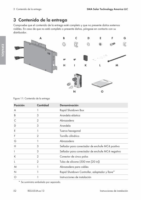
3 Contenido de la entregaCompruebe que el contenido de la entrega esté completo y que no presente daños externosvisibles. En caso de que no esté completo o presente daños, póngase en contacto con sudistribuidor.
Figure 11: Contenido de la entrega
Posición Cantidad DenominaciónA 1 Rapid Shutdown Box
B 3 Arandela elástica
C 2 Abrazadera
D 3 Arandela
E 1 Tuerca hexagonal
F 2 Tornillo cilíndrico
G 1 Abrazadera
H 3 Sellador para conectador de enchufe MC4 positivo
I 3 Sellador para conectador de enchufe MC4 negativo
K 2 Conector de cinco polos
L 2 Tubo de silicona (500 mm [20 in])
M 1 Abrazadera para cables
N 1 Rapid Shutdown Controller, adaptador y llave*
O 1 Instrucciones de instalación* Se suministra embalado por separado.
3 Contenido de la entrega SMA Solar Technology America LLC
Instrucciones de instalaciónRSS-US-IA-xx-1352
ESPAÑ
OL
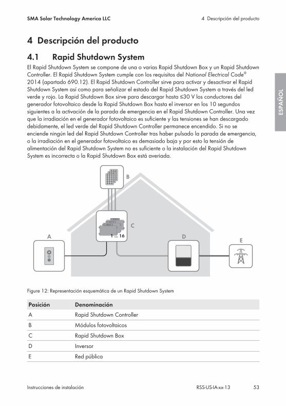
4 Descripción del producto
4.1 Rapid Shutdown SystemEl Rapid Shutdown System se compone de una o varias Rapid Shutdown Box y un Rapid ShutdownController. El Rapid Shutdown System cumple con los requisitos del National Electrical Code®
2014 (apartado 690.12). El Rapid Shutdown Controller sirve para activar y desactivar el RapidShutdown System así como para señalizar el estado del Rapid Shutdown System a través del ledverde y rojo. La Rapid Shutdown Box sirve para descargar hasta ≤30 V los conductores delgenerador fotovoltaico desde la Rapid Shutdown Box hasta el inversor en los 10 segundossiguientes a la activación de la parada de emergencia en el Rapid Shutdown Controller. Una vezque la irradiación en el generador fotovoltaico es suficiente y las tensiones se han descargadodebidamente, el led verde del Rapid Shutdown Controller permanece encendido. Si no seenciende ningún led del Rapid Shutdown Controller tras haber pulsado la parada de emergencia,o la irradiación en el generador fotovoltaico es demasiado baja y por esto la tensión dealimentación del Rapid Shutdown System no es suficiente o la instalación del Rapid ShutdownSystem es incorrecta o la Rapid Shutdown Box está averiada.
A DE
1 ... 16
B
C
Figure 12: Representación esquemática de un Rapid Shutdown System
Posición DenominaciónA Rapid Shutdown Controller
B Módulos fotovoltaicos
C Rapid Shutdown Box
D Inversor
E Red pública
4 Descripción del productoSMA Solar Technology America LLC
Instrucciones de instalación 53RSS-US-IA-xx-13
ESPA
ÑO
L
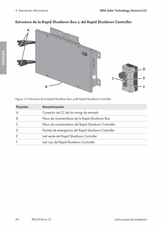
Estructura de la Rapid Shutdown Box y del Rapid Shutdown Controller
Figure 13: Estructura de la Rapid Shutdown Box y del Rapid Shutdown Controller
Posición DenominaciónA Conexión de CC de los strings de entrada
B Placa de características de la Rapid Shutdown Box
C Placa de características del Rapid Shutdown Controller
D Parada de emergencia del Rapid Shutdown Controller
E Led verde del Rapid Shutdown Controller
F Led rojo del Rapid Shutdown Controller
4 Descripción del producto SMA Solar Technology America LLC
Instrucciones de instalaciónRSS-US-IA-xx-1354
ESPAÑ
OL
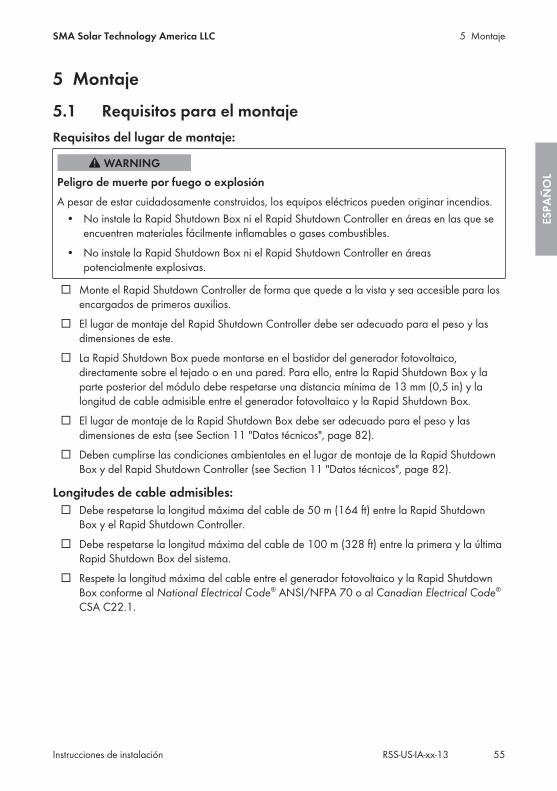
5 Montaje
5.1 Requisitos para el montajeRequisitos del lugar de montaje:
Peligro de muerte por fuego o explosiónA pesar de estar cuidadosamente construidos, los equipos eléctricos pueden originar incendios.
• No instale la Rapid Shutdown Box ni el Rapid Shutdown Controller en áreas en las que seencuentren materiales fácilmente inflamables o gases combustibles.
• No instale la Rapid Shutdown Box ni el Rapid Shutdown Controller en áreaspotencialmente explosivas.
☐ Monte el Rapid Shutdown Controller de forma que quede a la vista y sea accesible para losencargados de primeros auxilios.
☐ El lugar de montaje del Rapid Shutdown Controller debe ser adecuado para el peso y lasdimensiones de este.
☐ La Rapid Shutdown Box puede montarse en el bastidor del generador fotovoltaico,directamente sobre el tejado o en una pared. Para ello, entre la Rapid Shutdown Box y laparte posterior del módulo debe respetarse una distancia mínima de 13 mm (0,5 in) y lalongitud de cable admisible entre el generador fotovoltaico y la Rapid Shutdown Box.
☐ El lugar de montaje de la Rapid Shutdown Box debe ser adecuado para el peso y lasdimensiones de esta (see Section 11 "Datos técnicos", page 82).
☐ Deben cumplirse las condiciones ambientales en el lugar de montaje de la Rapid ShutdownBox y del Rapid Shutdown Controller (see Section 11 "Datos técnicos", page 82).
Longitudes de cable admisibles:☐ Debe respetarse la longitud máxima del cable de 50 m (164 ft) entre la Rapid Shutdown
Box y el Rapid Shutdown Controller.☐ Debe respetarse la longitud máxima del cable de 100 m (328 ft) entre la primera y la última
Rapid Shutdown Box del sistema.☐ Respete la longitud máxima del cable entre el generador fotovoltaico y la Rapid Shutdown
Box conforme al National Electrical Code® ANSI/NFPA 70 o al Canadian Electrical Code®
CSA C22.1.
5 MontajeSMA Solar Technology America LLC
Instrucciones de instalación 55RSS-US-IA-xx-13
ESPA
ÑO
L
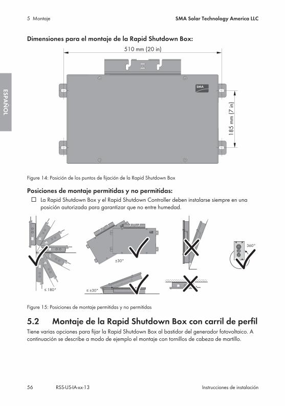
Dimensiones para el montaje de la Rapid Shutdown Box:
Figure 14: Posición de los puntos de fijación de la Rapid Shutdown Box
Posiciones de montaje permitidas y no permitidas:☐ La Rapid Shutdown Box y el Rapid Shutdown Controller deben instalarse siempre en una
posición autorizada para garantizar que no entre humedad.
Figure 15: Posiciones de montaje permitidas y no permitidas
5.2 Montaje de la Rapid Shutdown Box con carril de perfilTiene varias opciones para fijar la Rapid Shutdown Box al bastidor del generador fotovoltaico. Acontinuación se describe a modo de ejemplo el montaje con tornillos de cabeza de martillo.
5 Montaje SMA Solar Technology America LLC
Instrucciones de instalaciónRSS-US-IA-xx-1356
ESPAÑ
OL
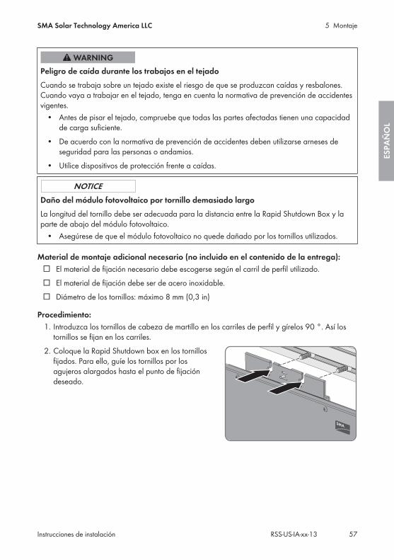
Peligro de caída durante los trabajos en el tejadoCuando se trabaja sobre un tejado existe el riesgo de que se produzcan caídas y resbalones.Cuando vaya a trabajar en el tejado, tenga en cuenta la normativa de prevención de accidentesvigentes.
• Antes de pisar el tejado, compruebe que todas las partes afectadas tienen una capacidadde carga suficiente.
• De acuerdo con la normativa de prevención de accidentes deben utilizarse arneses deseguridad para las personas o andamios.
• Utilice dispositivos de protección frente a caídas.
Daño del módulo fotovoltaico por tornillo demasiado largoLa longitud del tornillo debe ser adecuada para la distancia entre la Rapid Shutdown Box y laparte de abajo del módulo fotovoltaico.
• Asegúrese de que el módulo fotovoltaico no quede dañado por los tornillos utilizados.
Material de montaje adicional necesario (no incluido en el contenido de la entrega):☐ El material de fijación necesario debe escogerse según el carril de perfil utilizado.☐ El material de fijación debe ser de acero inoxidable.☐ Diámetro de los tornillos: máximo 8 mm (0,3 in)
Procedimiento:1. Introduzca los tornillos de cabeza de martillo en los carriles de perfil y gírelos 90 °. Así los
tornillos se fijan en los carriles.2. Coloque la Rapid Shutdown box en los tornillos
fijados. Para ello, guíe los tornillos por losagujeros alargados hasta el punto de fijacióndeseado.
5 MontajeSMA Solar Technology America LLC
Instrucciones de instalación 57RSS-US-IA-xx-13
ESPA
ÑO
L
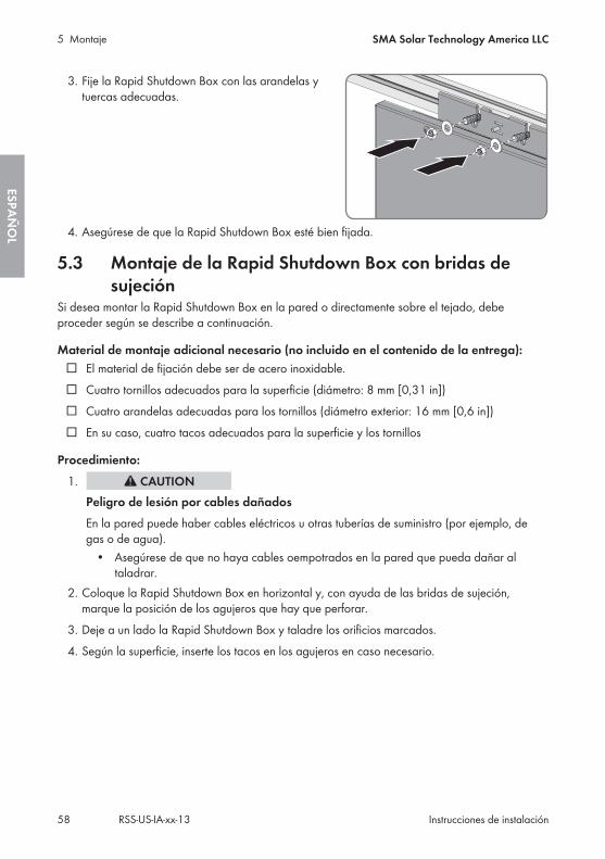
3. Fije la Rapid Shutdown Box con las arandelas ytuercas adecuadas.
4. Asegúrese de que la Rapid Shutdown Box esté bien fijada.
5.3 Montaje de la Rapid Shutdown Box con bridas desujeción
Si desea montar la Rapid Shutdown Box en la pared o directamente sobre el tejado, debeproceder según se describe a continuación.
Material de montaje adicional necesario (no incluido en el contenido de la entrega):☐ El material de fijación debe ser de acero inoxidable.☐ Cuatro tornillos adecuados para la superficie (diámetro: 8 mm [0,31 in])☐ Cuatro arandelas adecuadas para los tornillos (diámetro exterior: 16 mm [0,6 in])☐ En su caso, cuatro tacos adecuados para la superficie y los tornillos
Procedimiento:1.
Peligro de lesión por cables dañadosEn la pared puede haber cables eléctricos u otras tuberías de suministro (por ejemplo, degas o de agua).
• Asegúrese de que no haya cables oempotrados en la pared que pueda dañar altaladrar.
2. Coloque la Rapid Shutdown Box en horizontal y, con ayuda de las bridas de sujeción,marque la posición de los agujeros que hay que perforar.
3. Deje a un lado la Rapid Shutdown Box y taladre los orificios marcados.4. Según la superficie, inserte los tacos en los agujeros en caso necesario.
5 Montaje SMA Solar Technology America LLC
Instrucciones de instalaciónRSS-US-IA-xx-1358
ESPAÑ
OL
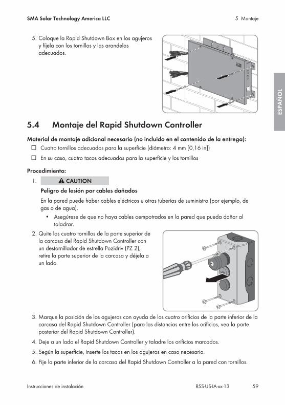
5. Coloque la Rapid Shutdown Box en los agujerosy fíjela con los tornillos y las arandelasadecuados.
5.4 Montaje del Rapid Shutdown ControllerMaterial de montaje adicional necesario (no incluido en el contenido de la entrega):
☐ Cuatro tornillos adecuados para la superficie (diámetro: 4 mm [0,16 in])☐ En su caso, cuatro tacos adecuados para la superficie y los tornillos
Procedimiento:1.
Peligro de lesión por cables dañadosEn la pared puede haber cables eléctricos u otras tuberías de suministro (por ejemplo, degas o de agua).
• Asegúrese de que no haya cables oempotrados en la pared que pueda dañar altaladrar.
2. Quite los cuatro tornillos de la parte superior dela carcasa del Rapid Shutdown Controller conun destornillador de estrella Pozidriv (PZ 2),retire la parte superior de la carcasa y déjela aun lado.
3. Marque la posición de los agujeros con ayuda de los cuatro orificios de la parte inferior de lacarcasa del Rapid Shutdown Controller (para las distancias entre los orificios, vea la parteposterior del Rapid Shutdown Controller).
4. Deje a un lado el Rapid Shutdown Controller y taladre los orificios marcados.5. Según la superficie, inserte los tacos en los agujeros en caso necesario.6. Fije la parte inferior de la carcasa del Rapid Shutdown Controller a la pared con tornillos.
5 MontajeSMA Solar Technology America LLC
Instrucciones de instalación 59RSS-US-IA-xx-13
ESPA
ÑO
L
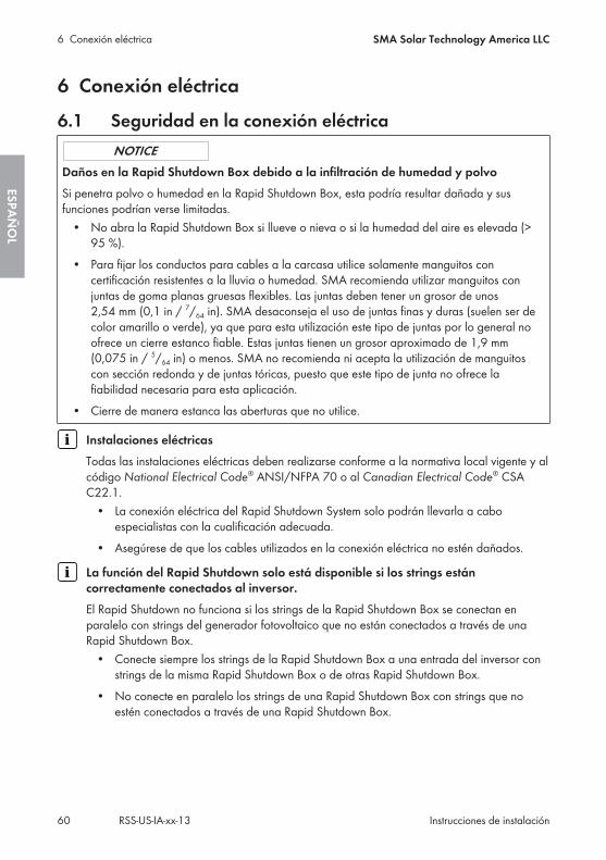
6 Conexión eléctrica
6.1 Seguridad en la conexión eléctrica
Daños en la Rapid Shutdown Box debido a la infiltración de humedad y polvoSi penetra polvo o humedad en la Rapid Shutdown Box, esta podría resultar dañada y susfunciones podrían verse limitadas.
• No abra la Rapid Shutdown Box si llueve o nieva o si la humedad del aire es elevada (>95 %).
• Para fijar los conductos para cables a la carcasa utilice solamente manguitos concertificación resistentes a la lluvia o humedad. SMA recomienda utilizar manguitos conjuntas de goma planas gruesas flexibles. Las juntas deben tener un grosor de unos2,54 mm (0,1 in / 7/64 in). SMA desaconseja el uso de juntas finas y duras (suelen ser decolor amarillo o verde), ya que para esta utilización este tipo de juntas por lo general noofrece un cierre estanco fiable. Estas juntas tienen un grosor aproximado de 1,9 mm(0,075 in / 5/64 in) o menos. SMA no recomienda ni acepta la utilización de manguitoscon sección redonda y de juntas tóricas, puesto que este tipo de junta no ofrece lafiabilidad necesaria para esta aplicación.
• Cierre de manera estanca las aberturas que no utilice.
Instalaciones eléctricasTodas las instalaciones eléctricas deben realizarse conforme a la normativa local vigente y alcódigo National Electrical Code® ANSI/NFPA 70 o al Canadian Electrical Code® CSAC22.1.
• La conexión eléctrica del Rapid Shutdown System solo podrán llevarla a caboespecialistas con la cualificación adecuada.
• Asegúrese de que los cables utilizados en la conexión eléctrica no estén dañados.
La función del Rapid Shutdown solo está disponible si los strings estáncorrectamente conectados al inversor.El Rapid Shutdown no funciona si los strings de la Rapid Shutdown Box se conectan enparalelo con strings del generador fotovoltaico que no están conectados a través de unaRapid Shutdown Box.
• Conecte siempre los strings de la Rapid Shutdown Box a una entrada del inversor constrings de la misma Rapid Shutdown Box o de otras Rapid Shutdown Box.
• No conecte en paralelo los strings de una Rapid Shutdown Box con strings que noestén conectados a través de una Rapid Shutdown Box.
6 Conexión eléctrica SMA Solar Technology America LLC
Instrucciones de instalaciónRSS-US-IA-xx-1360
ESPAÑ
OL
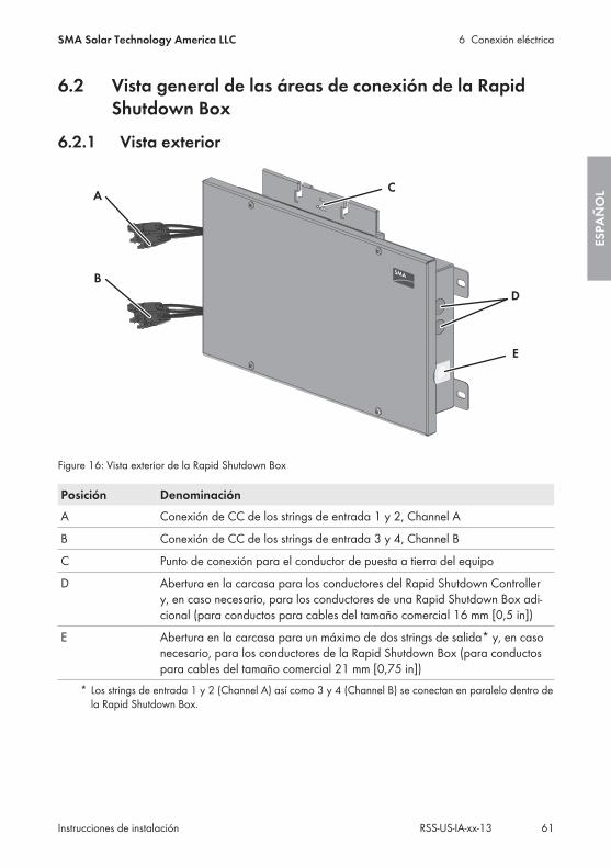
6.2 Vista general de las áreas de conexión de la RapidShutdown Box
6.2.1 Vista exterior
+
+
+
+
A
D
E
B
C
Figure 16: Vista exterior de la Rapid Shutdown Box
Posición DenominaciónA Conexión de CC de los strings de entrada 1 y 2, Channel A
B Conexión de CC de los strings de entrada 3 y 4, Channel B
C Punto de conexión para el conductor de puesta a tierra del equipo
D Abertura en la carcasa para los conductores del Rapid Shutdown Controllery, en caso necesario, para los conductores de una Rapid Shutdown Box adi-cional (para conductos para cables del tamaño comercial 16 mm [0,5 in])
E Abertura en la carcasa para un máximo de dos strings de salida* y, en casonecesario, para los conductores de la Rapid Shutdown Box (para conductospara cables del tamaño comercial 21 mm [0,75 in])
* Los strings de entrada 1 y 2 (Channel A) así como 3 y 4 (Channel B) se conectan en paralelo dentro dela Rapid Shutdown Box.
6 Conexión eléctricaSMA Solar Technology America LLC
Instrucciones de instalación 61RSS-US-IA-xx-13
ESPA
ÑO
L
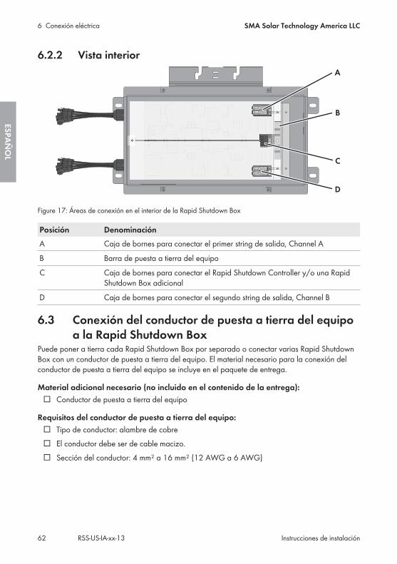
6.2.2 Vista interior
Figure 17: Áreas de conexión en el interior de la Rapid Shutdown Box
Posición DenominaciónA Caja de bornes para conectar el primer string de salida, Channel A
B Barra de puesta a tierra del equipo
C Caja de bornes para conectar el Rapid Shutdown Controller y/o una RapidShutdown Box adicional
D Caja de bornes para conectar el segundo string de salida, Channel B
6.3 Conexión del conductor de puesta a tierra del equipoa la Rapid Shutdown Box
Puede poner a tierra cada Rapid Shutdown Box por separado o conectar varias Rapid ShutdownBox con un conductor de puesta a tierra del equipo. El material necesario para la conexión delconductor de puesta a tierra del equipo se incluye en el paquete de entrega.
Material adicional necesario (no incluido en el contenido de la entrega):☐ Conductor de puesta a tierra del equipo
Requisitos del conductor de puesta a tierra del equipo:☐ Tipo de conductor: alambre de cobre☐ El conductor debe ser de cable macizo.☐ Sección del conductor: 4 mm² a 16 mm² (12 AWG a 6 AWG)
6 Conexión eléctrica SMA Solar Technology America LLC
Instrucciones de instalaciónRSS-US-IA-xx-1362
ESPAÑ
OL
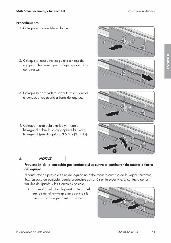
Procedimiento:1. Coloque una arandela en la rosca.
2. Coloque el conductor de puesta a tierra delequipo en horizontal por debajo o por encimade la rosca.
3. Coloque la abrazadera sobre la rosca y sobreel conductor de puesta a tierra del equipo.
4. Coloque 1 arandela elástica y 1 tuercahexagonal sobre la rosca y apriete la tuercahexagonal (par de apriete: 3,5 Nm [31 in-lb]).
5.Prevención de la corrosión por contacto si se curva el conductor de puesta a tierradel equipoEl conductor de puesta a tierra del equipo no debe tocar la carcasa de la Rapid ShutdownBox. En caso de contacto, puede producirse corrosión en la superficie. El contacto de lostornillos de fijación y las tuercas es posible.
• Curve el conductor de puesta a tierra delequipo de tal forma que no apoye en lacarcasa de la Rapid Shutdown Box.
6 Conexión eléctricaSMA Solar Technology America LLC
Instrucciones de instalación 63RSS-US-IA-xx-13
ESPA
ÑO
L
6.4 Conexión entre sí de Rapid Shutdown Box y RapidShutdown Controller
Material adicional necesario (no incluido en el contenido de la entrega):☐ Conducto para cables: O bien tienda un conducto para cables propio (tamaño comercial:
16 mm [0,5 in] o inferior con reductores adecuados) o tienda los conductores conjuntamenteen el conducto para cables de los strings de salida.
☐ Si utiliza un conducto para cables propio para tender los conductores para la conexión delRapid Shutdown Controller: manguito resistente a la lluvia o humedad (tamaño comercial:16 mm [0,5 in] o inferior con reductores adecuados)
☐ Si tiende un Tray Cable for exposed run (TC-ER), emplee un racor atornillado para cablesadecuado para el cable y la abertura en la carcasa.
Requisitos de los conductores:☐ En caso de tendido en exteriores sin conducto para cables, debe utilizarse un Tray Cable for
exposed run (TC-ER).☐ Tipo de conductor: alambre de cobre☐ Número de conductores: 5☐ Si los conductores para la conexión del Rapid Shutdown Controller están tendidos en un
conducto para cables junto con los strings de salida, los conductores para la conexión delRapid Shutdown Controller deben estar aislados para la tensión maxima del sistemafotovoltaico.
☐ Los cables deben ser de cable macizo, cordón o cordón fino. Si se usan cordones finosdeben utilizarse virolas.
☐ Sección del conductor: 0,75 mm² a 1,5 mm² (18 AWG a 16 AWG)☐ Longitud máxima de los conductores entre la Rapid Shutdown Box y el Rapid Shutdown
Controller: 50 m (164 ft)
Cumplimiento con los requisitos de la clase 2 de conmutacionesEl circuito de detección del Rapid Shutdown Controllers cumple con los requisitos de la clase2 de conmutaciones. La tensión en vacío máxima es de 20 V y la corriente de cortocircuitomáxima es de 400 mA.
Indicación para el tendido de Tray Cables for exposed run (TC-ER)En este capítulo se describe si se utilizan conductos para cables. En lugar de conductos paracables también pueden usarse Tray Cable for exposed run (TC-ER).
• Si utiliza Tray Cables for exposed run (TC-ER), seleccione racores atornillados paracables adecuados y colóquelos en la abertura en la carcasa en lugar de los conductospara cables. Asegúrese de que la abertura en la carcasa sea estanca y no entrehumedad.
6 Conexión eléctrica SMA Solar Technology America LLC
Instrucciones de instalaciónRSS-US-IA-xx-1364
ESPAÑ
OL
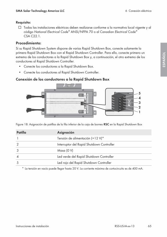
Requisito:☐ Todas las instalaciones eléctricas deben realizarse conforme a la normativa local vigente y al
código National Electrical Code® ANSI/NFPA 70 o al Canadian Electrical Code®
CSA C22.1.
Procedimiento:Si su Rapid Shutdown System dispone de varias Rapid Shutdown Box, conecte solamente laprimera Rapid Shutdown Box con el Rapid Shutdown Controller. Para ello, conecte primero unextremo de los conductores a la Rapid Shutdown Box y, a continuación, el otro extremo de losconductores al Rapid Shutdown Controller.
• Conecte los conductores a la Rapid Shutdown Box.• Conecte los conductores al Rapid Shutdown Controller.
Conexión de los conductores a la Rapid Shutdown Box
Figure 18: Asignación de patillas de la fila inferior de la caja de bornes RSC en la Rapid Shutdown Box
Patilla Asignación1 Tensión de alimentación (+12 V)*
2 Interruptor del Rapid Shutdown Controller
3 Masa (0 V)
4 Led verde del Rapid Shutdown Controller
5 Led rojo del Rapid Shutdown Controller* La tensión en vacío puede llegar hasta 20 V. La corriente máxima de cortocircuito es de 400 mA.
6 Conexión eléctricaSMA Solar Technology America LLC
Instrucciones de instalación 65RSS-US-IA-xx-13
ESPA
ÑO
L
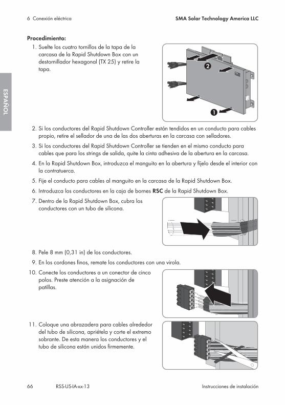
Procedimiento:1. Suelte los cuatro tornillos de la tapa de la
carcasa de la Rapid Shutdown Box con undestornillador hexagonal (TX 25) y retire latapa.
2. Si los conductores del Rapid Shutdown Controller están tendidos en un conducto para cablespropio, retire el sellador de una de las dos aberturas en la carcasa con selladores.
3. Si los conductores del Rapid Shutdown Controller se tienden en el mismo conducto paracables que para los strings de salida, quite la cinta adhesiva de la abertura en la carcasa.
4. En la Rapid Shutdown Box, introduzca el manguito en la abertura y fíjelo desde el interior conla contratuerca.
5. Fije el conducto para cables al manguito en la carcasa de la Rapid Shutdown Box.6. Introduzca los conductores en la caja de bornes RSC de la Rapid Shutdown Box.7. Dentro de la Rapid Shutdown Box, cubra los
conductores con un tubo de silicona.
8. Pele 8 mm (0,31 in) de los conductores.9. En los cordones finos, remate los conductores con una virola.
10. Conecte los conductores a un conector de cincopolos. Preste atención a la asignación depatillas.
11. Coloque una abrazadera para cables alrededordel tubo de silicona, apriétela y corte el extremosobrante. De esta manera los conductores y eltubo de silicona están unidos firmemente.
6 Conexión eléctrica SMA Solar Technology America LLC
Instrucciones de instalaciónRSS-US-IA-xx-1366
ESPAÑ
OL
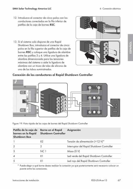
12. Introduzca el conector de cinco polos con losconductores conectados en la fila inferior depatillas de la caja de bornes RSC.
13. Si el sistema solo dispone de una RapidShutdown Box, introduzca el conector de cincopolos en la fila superior de patillas de la caja debornes RSC y coloque una ligadura de alambreentre las patillas 3 y 4. Utilice una ligadura dealambre dimensionada para las tensionesmáximas del sistema o aísle la ligadura dealambre con un trozo de tubo de silicona deuno de los tubos suministrados.
Conexión de los conductores al Rapid Shutdown Controller
+
A −
− B
+R
SC
NC
12
X12
X
X12
X
NC
12
X12
X
X12
X
12345
Figure 19: Vista rápida de las cajas de bornes del Rapid Shutdown Controller
Patilla de la caja debornes en la RapidShutdown Box
Borne en el RapidShutdown Controller
Asignación
1 X2 Tensión de alimentación (+12 V)*
2 2 Interruptor del Rapid Shutdown Controller
3 NC 1 Masa (0 V)
4 X1 Led verde del Rapid Shutdown Controller
5 X1 Led rojo del Rapid Shutdown Controller* Puede elegir a qué borne desea realizar la conexión ya que posteriormente será necesario colocar un
puente entre las conexiones.
6 Conexión eléctricaSMA Solar Technology America LLC
Instrucciones de instalación 67RSS-US-IA-xx-13
ESPA
ÑO
L
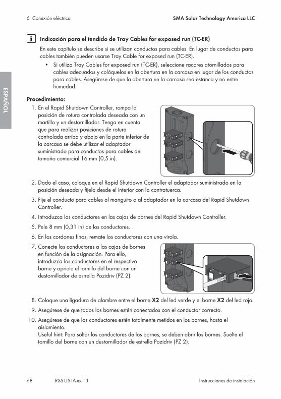
Indicación para el tendido de Tray Cables for exposed run (TC-ER)En este capítulo se describe si se utilizan conductos para cables. En lugar de conductos paracables también pueden usarse Tray Cable for exposed run (TC-ER).
• Si utiliza Tray Cables for exposed run (TC-ER), seleccione racores atornillados paracables adecuados y colóquelos en la abertura en la carcasa en lugar de los conductospara cables. Asegúrese de que la abertura en la carcasa sea estanca y no entrehumedad.
Procedimiento:1. En el Rapid Shutdown Controller, rompa la
posición de rotura controlada deseada con unmartillo y un destornillador. Tenga en cuentaque para realizar posiciones de roturacontrolada arriba y abajo en la parte inferior dela carcasa se debe utilizar el adaptadorsuministrado para conductos para cables deltamaño comercial 16 mm (0,5 in).
2. Dado el caso, coloque en el Rapid Shutdown Controller el adaptador suministrado en laposición deseada y fíjelo desde el interior con la contratuerca.
3. Fije el conducto para cables al manguito o al adaptador en la carcasa del Rapid ShutdownController.
4. Introduzca los conductores en las cajas de bornes del Rapid Shutdown Controller.5. Pele 8 mm (0,31 in) de los conductores.6. En los cordones finos, remate los conductores con una virola.7. Conecte los conductores a las cajas de bornes
en función de la asignación. Para ello,introduzca los conductores en el respectivoborne y apriete el tornillo del borne con undestornillador de estrella Pozidriv (PZ 2).
8. Coloque una ligadura de alambre entre el borne X2 del led verde y el borne X2 del led rojo.9. Asegúrese de que todos los bornes estén conectados con el conductor correcto.
10. Asegúrese de que los conductores estén totalmente metidos en los bornes, hasta elaislamiento. Useful hint: Para soltar los conductores de los bornes, se deben abrir los bornes. Suelte eltornillo del borne con un destornillador de estrella Pozidriv (PZ 2).
6 Conexión eléctrica SMA Solar Technology America LLC
Instrucciones de instalaciónRSS-US-IA-xx-1368
ESPAÑ
OL
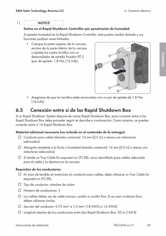
11.Daños en el Rapid Shutdown Controller por penetración de humedadSi penetra humedad en la Rapid Shutdown Controller, éste podría resultar dañado y susfunciones podrían verse limitadas.
• Coloque la parte superior de la carcasaencima de la parte inferior de la carcasay apriete los cuatro tornillos con undestornillador de estrella Pozidriv PZ 2(par de apriete: 1,8 Nm (16 in-lb).
• Asegúrese de que los tornillos estén enroscados con un par de apriete de 1,8 Nm(16 in-lb).
6.5 Conexión entre sí de las Rapid Shutdown BoxSi su Rapid Shutdown System dispone de varias Rapid Shutdown Box, para conectar entre sí lasRapid Shutdown Box debe proceder según se describe a continuación. Como máximo, se puedenconectar entre sí 16 Rapid Shutdown Box.
Material adicional necesario (no incluido en el contenido de la entrega):☐ Conducto para cables (tamaño comercial: 16 mm [0,5 in] o menos con reductores
adecuados)☐ Manguito resistente a la lluvia o humedad (tamaño comercial: 16 mm [0,5 in] o menos con
reductores adecuados)☐ Si tiende un Tray Cable for exposed run (TC-ER): racor atornillado para cables adecuado
para el cable y la abertura en la carcasa
Requisitos de los conductores:☐ En caso de tendido en exteriores sin conducto para cables, debe utilizarse un Tray Cable for
exposed run (TC-ER).☐ Tipo de conductor: alambre de cobre☐ Número de conductores: 5☐ Los cables deben ser de cable macizo, cordón o cordón fino. Si se usan cordones finos
deben utilizarse virolas.☐ Sección del conductor: 0,75 mm² a 1,5 mm² (18 AWG a 16 AWG)☐ Longitud máxima de los conductores entre dos Rapid Shutdown Box: 50 m (164 ft)
6 Conexión eléctricaSMA Solar Technology America LLC
Instrucciones de instalación 69RSS-US-IA-xx-13
ESPA
ÑO
L
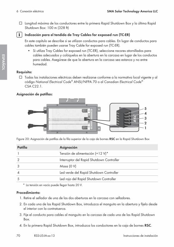
☐ Longitud máxima de los conductores entre la primera Rapid Shutdown Box y la última RapidShutdown Box: 100 m (328 ft)
Indicación para el tendido de Tray Cables for exposed run (TC-ER)En este capítulo se describe si se utilizan conductos para cables. En lugar de conductos paracables también pueden usarse Tray Cable for exposed run (TC-ER).
• Si utiliza Tray Cables for exposed run (TC-ER), seleccione racores atornillados paracables adecuados y colóquelos en la abertura en la carcasa en lugar de los conductospara cables. Asegúrese de que la abertura en la carcasa sea estanca y no entrehumedad.
Requisito:☐ Todas las instalaciones eléctricas deben realizarse conforme a la normativa local vigente y al
código National Electrical Code® ANSI/NFPA 70 o al Canadian Electrical Code®
CSA C22.1.
Asignación de patillas:
Figure 20: Asignación de patillas de la fila superior de la caja de bornes RSC en la Rapid Shutdown Box
Patilla Asignación1 Tensión de alimentación (+12 V)*
2 Interruptor del Rapid Shutdown Controller
3 Masa (0 V)
4 Led verde del Rapid Shutdown Controller
5 Led rojo del Rapid Shutdown Controller* La tensión en vacío puede llegar hasta 20 V.
Procedimiento:1. Retire el sellador de una de las dos aberturas en la carcasa con selladores.2. En cada una de las Rapid Shutdown Box, introduzca el manguito en la abertura y fíjelo desde
el interior con la contratuerca.3. Fije el conducto para cables al manguito en la carcasa de cada una de las Rapid Shutdown
Box.4. En la primera Rapid Shutdown Box, introduzca los conductores en la caja de bornes RSC.
6 Conexión eléctrica SMA Solar Technology America LLC
Instrucciones de instalaciónRSS-US-IA-xx-1370
ESPAÑ
OL
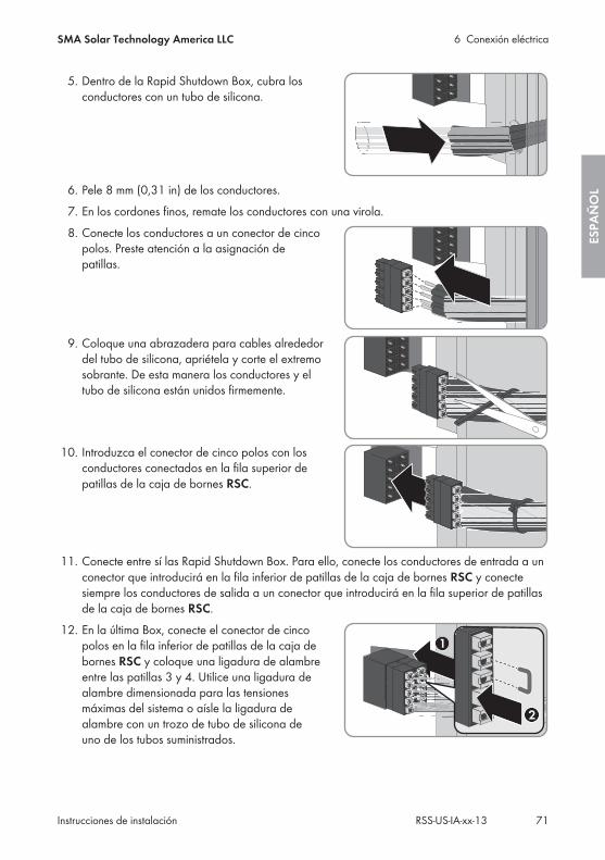
5. Dentro de la Rapid Shutdown Box, cubra losconductores con un tubo de silicona.
6. Pele 8 mm (0,31 in) de los conductores.7. En los cordones finos, remate los conductores con una virola.8. Conecte los conductores a un conector de cinco
polos. Preste atención a la asignación depatillas.
9. Coloque una abrazadera para cables alrededordel tubo de silicona, apriétela y corte el extremosobrante. De esta manera los conductores y eltubo de silicona están unidos firmemente.
10. Introduzca el conector de cinco polos con losconductores conectados en la fila superior depatillas de la caja de bornes RSC.
11. Conecte entre sí las Rapid Shutdown Box. Para ello, conecte los conductores de entrada a unconector que introducirá en la fila inferior de patillas de la caja de bornes RSC y conectesiempre los conductores de salida a un conector que introducirá en la fila superior de patillasde la caja de bornes RSC.
12. En la última Box, conecte el conector de cincopolos en la fila inferior de patillas de la caja debornes RSC y coloque una ligadura de alambreentre las patillas 3 y 4. Utilice una ligadura dealambre dimensionada para las tensionesmáximas del sistema o aísle la ligadura dealambre con un trozo de tubo de silicona deuno de los tubos suministrados.
6 Conexión eléctricaSMA Solar Technology America LLC
Instrucciones de instalación 71RSS-US-IA-xx-13
ESPA
ÑO
L
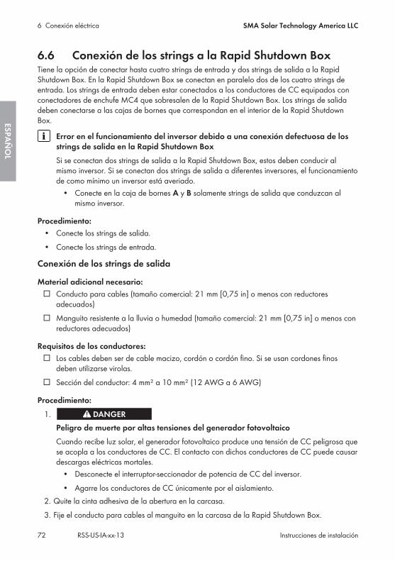
6.6 Conexión de los strings a la Rapid Shutdown BoxTiene la opción de conectar hasta cuatro strings de entrada y dos strings de salida a la RapidShutdown Box. En la Rapid Shutdown Box se conectan en paralelo dos de los cuatro strings deentrada. Los strings de entrada deben estar conectados a los conductores de CC equipados conconectadores de enchufe MC4 que sobresalen de la Rapid Shutdown Box. Los strings de salidadeben conectarse a las cajas de bornes que correspondan en el interior de la Rapid ShutdownBox.
Error en el funcionamiento del inversor debido a una conexión defectuosa de losstrings de salida en la Rapid Shutdown BoxSi se conectan dos strings de salida a la Rapid Shutdown Box, estos deben conducir almismo inversor. Si se conectan dos strings de salida a diferentes inversores, el funcionamientode como mínimo un inversor está averiado.
• Conecte en la caja de bornes A y B solamente strings de salida que conduzcan almismo inversor.
Procedimiento:• Conecte los strings de salida.• Conecte los strings de entrada.
Conexión de los strings de salida
Material adicional necesario:☐ Conducto para cables (tamaño comercial: 21 mm [0,75 in] o menos con reductores
adecuados)☐ Manguito resistente a la lluvia o humedad (tamaño comercial: 21 mm [0,75 in] o menos con
reductores adecuados)
Requisitos de los conductores:☐ Los cables deben ser de cable macizo, cordón o cordón fino. Si se usan cordones finos
deben utilizarse virolas.☐ Sección del conductor: 4 mm² a 10 mm² (12 AWG a 6 AWG)
Procedimiento:1.
Peligro de muerte por altas tensiones del generador fotovoltaicoCuando recibe luz solar, el generador fotovoltaico produce una tensión de CC peligrosa quese acopla a los conductores de CC. El contacto con dichos conductores de CC puede causardescargas eléctricas mortales.
• Desconecte el interruptor-seccionador de potencia de CC del inversor.• Agarre los conductores de CC únicamente por el aislamiento.
2. Quite la cinta adhesiva de la abertura en la carcasa.3. Fije el conducto para cables al manguito en la carcasa de la Rapid Shutdown Box.
6 Conexión eléctrica SMA Solar Technology America LLC
Instrucciones de instalaciónRSS-US-IA-xx-1372
ESPAÑ
OL
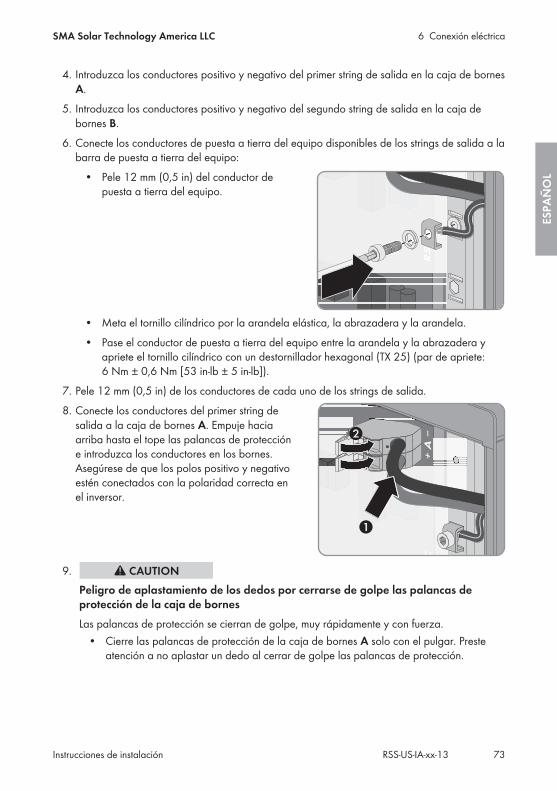
4. Introduzca los conductores positivo y negativo del primer string de salida en la caja de bornesA.
5. Introduzca los conductores positivo y negativo del segundo string de salida en la caja debornes B.
6. Conecte los conductores de puesta a tierra del equipo disponibles de los strings de salida a labarra de puesta a tierra del equipo:
• Pele 12 mm (0,5 in) del conductor depuesta a tierra del equipo.
• Meta el tornillo cilíndrico por la arandela elástica, la abrazadera y la arandela.• Pase el conductor de puesta a tierra del equipo entre la arandela y la abrazadera y
apriete el tornillo cilíndrico con un destornillador hexagonal (TX 25) (par de apriete:6 Nm ± 0,6 Nm [53 in-lb ± 5 in-lb]).
7. Pele 12 mm (0,5 in) de los conductores de cada uno de los strings de salida.8. Conecte los conductores del primer string de
salida a la caja de bornes A. Empuje haciaarriba hasta el tope las palancas de proteccióne introduzca los conductores en los bornes.Asegúrese de que los polos positivo y negativoestén conectados con la polaridad correcta enel inversor.
9.Peligro de aplastamiento de los dedos por cerrarse de golpe las palancas deprotección de la caja de bornesLas palancas de protección se cierran de golpe, muy rápidamente y con fuerza.
• Cierre las palancas de protección de la caja de bornes A solo con el pulgar. Presteatención a no aplastar un dedo al cerrar de golpe las palancas de protección.
6 Conexión eléctricaSMA Solar Technology America LLC
Instrucciones de instalación 73RSS-US-IA-xx-13
ESPA
ÑO
L

10. Conecte los conductores del segundo string desalida a la caja de bornes B. Empuje haciaarriba hasta el tope las palancas de proteccióne introduzca los conductores en los bornes.Asegúrese de que los polos positivo y negativoestén conectados con la polaridad correcta enel inversor.
11.Peligro de aplastamiento de los dedos por cerrarse de golpe las palancas deprotección de la caja de bornesLas palancas de protección se cierran de golpe, muy rápidamente y con fuerza.
• Cierre las palancas de protección de la caja de bornes B solo con el pulgar. Presteatención a no aplastar un dedo al cerrar de golpe las palancas de protección.
12. Asegúrese de que todos los bornes estén conectados con el conductor correcto.13. Enganche la tapa de la carcasa en la lengüeta
del borde superior de la carcasa y apriete loscuatro tornillos con un destornillador hexagonal(TX 25) (par de apriete: 6 Nm ± 0,6 Nm [53 in-lb ± 5 in-lb]).
Conexión de los strings de entrada
Requisitos:☐ Los dos strings de cada entrada se conectan en paralelo en la Rapid Shutdown Box. Para la
conexión en paralelo de los strings de entrada es necesario dimensionar debidamente losstrings.
☐ No deben sobrepasarse las tensiones máximas admisibles del sistema del Rapid ShutdownSystem (see Section 11 "Datos técnicos", page 82).
☐ Cada uno de los conductores de CC positivos de un string debe estar equipado con unconectador de enchufe MC4 positivo (para obtener más información sobre la preparación,consulte las instrucciones del conectador de enchufe).
☐ Cada uno de los conductores de CC negativos de un string debe estar equipado con unconectador de enchufe MC4 negativo (para obtener más información sobre la preparación,consulte las instrucciones del conectador de enchufe).
6 Conexión eléctrica SMA Solar Technology America LLC
Instrucciones de instalaciónRSS-US-IA-xx-1374
ESPAÑ
OL
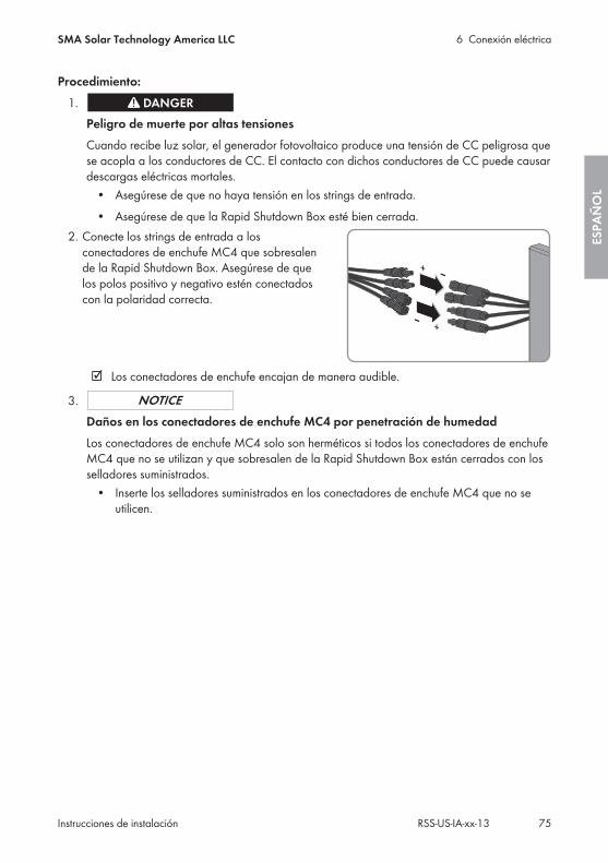
Procedimiento:1.
Peligro de muerte por altas tensionesCuando recibe luz solar, el generador fotovoltaico produce una tensión de CC peligrosa quese acopla a los conductores de CC. El contacto con dichos conductores de CC puede causardescargas eléctricas mortales.
• Asegúrese de que no haya tensión en los strings de entrada.• Asegúrese de que la Rapid Shutdown Box esté bien cerrada.
2. Conecte los strings de entrada a losconectadores de enchufe MC4 que sobresalende la Rapid Shutdown Box. Asegúrese de quelos polos positivo y negativo estén conectadoscon la polaridad correcta.
☑ Los conectadores de enchufe encajan de manera audible.
3.Daños en los conectadores de enchufe MC4 por penetración de humedadLos conectadores de enchufe MC4 solo son herméticos si todos los conectadores de enchufeMC4 que no se utilizan y que sobresalen de la Rapid Shutdown Box están cerrados con losselladores suministrados.
• Inserte los selladores suministrados en los conectadores de enchufe MC4 que no seutilicen.
6 Conexión eléctricaSMA Solar Technology America LLC
Instrucciones de instalación 75RSS-US-IA-xx-13
ESPA
ÑO
L
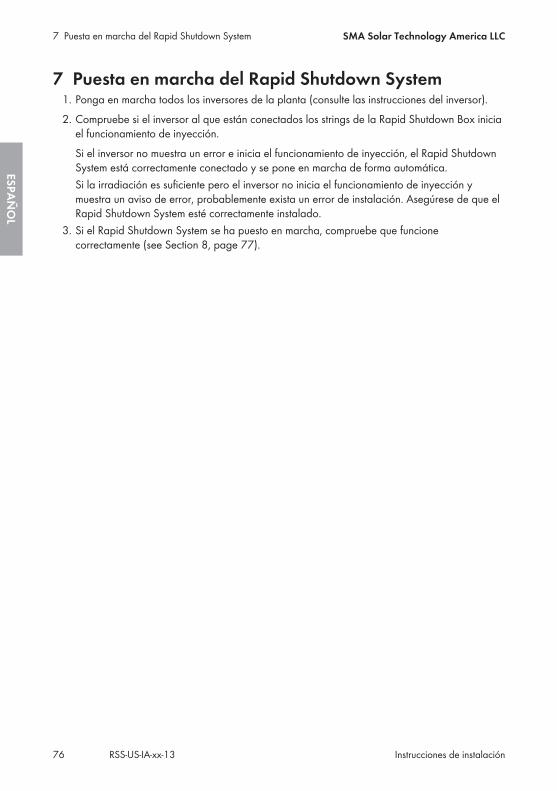
7 Puesta en marcha del Rapid Shutdown System1. Ponga en marcha todos los inversores de la planta (consulte las instrucciones del inversor).2. Compruebe si el inversor al que están conectados los strings de la Rapid Shutdown Box inicia
el funcionamiento de inyección.Si el inversor no muestra un error e inicia el funcionamiento de inyección, el Rapid ShutdownSystem está correctamente conectado y se pone en marcha de forma automática.Si la irradiación es suficiente pero el inversor no inicia el funcionamiento de inyección ymuestra un aviso de error, probablemente exista un error de instalación. Asegúrese de que elRapid Shutdown System esté correctamente instalado.
3. Si el Rapid Shutdown System se ha puesto en marcha, compruebe que funcionecorrectamente (see Section 8, page 77).
7 Puesta en marcha del Rapid Shutdown System SMA Solar Technology America LLC
Instrucciones de instalaciónRSS-US-IA-xx-1376
ESPAÑ
OL
8 Comprobación del correcto funcionamiento del RapidShutdown SystemEl Rapid Shutdown System se abastece del generador fotovoltaico. Si no hay suficiente irradiaciónen el generador fotovoltaico, la tensión de alimentación del Rapid Shutdown System es muy baja yno será posible comprobar el correcto funcionamiento del Rapid Shutdown System.
Requisito:☐ El Rapid Shutdown System debe estar en marcha.☐ Debe haber suficiente irradiación en el generador fotovoltaico.
Procedimiento:1. Pulse la parada de emergencia del Rapid Shutdown Controller. De esta forma, la
autocomprobación automática de la Rapid Shutdown Box se pone en marcha y se activa elRapid Shutdown System.
☑ El led rojo del Rapid Shutdown Controller se ilumina brevemente o parpadea. La RapidShutdown Box reduce la tensión en el lado de los strings de salida. Cuando la tensiónse encuentra dentro del rango permitido, el led verde del Rapid Shutdown Controllerpermanece encendido.
☑ El led verde del Rapid Shutdown Controller permanece encendido. El Rapid ShutdownSystem está activado y las tensiones en el lado de los strings de salida de la RapidShutdown Box son ≤30 V.
✖ ¿No se enciende ningún led del Rapid Shutdown Controller?Esto puede tener varias causas: o la irradiación en el generador fotovoltaico es muy bajay por eso la tensión de alimentación del Rapid Shutdown System no es suficiente o lainstalación del Rapid Shutdown System es incorrecta o la Rapid Shutdown Box estáaveriada.
• Asegúrese de que la tensión de alimentación del Rapid Shutdown System seasuficiente.
• Asegúrese de que la instalación del Rapid Shutdown System se haya realizadocorrectamente.
• Si la tensión de alimentación del Rapid Shutdown System es suficiente y suinstalación también es correcta pero no se enciende ningún LED, la RapidShutdown Box está averiada y se debe sustituir. Póngase en contacto con elservicio técnico (see Section 12 "Contacto", page 84).
✖ ¿El led rojo del Rapid Shutdown Controller permanece encendido?La Rapid Shutdown Box está averiada y el Rapid Shutdown System no está activado.
• Póngase en contacto con el servicio técnico (see Section 12 "Contacto",page 84).
2. Restablezca la función Rapid Shutdown (see Section 9.2, page 78).
8 Comprobación del correcto funcionamiento del Rapid ShutdownSystem
SMA Solar Technology America LLC
Instrucciones de instalación 77RSS-US-IA-xx-13
ESPA
ÑO
L
9 Manejo del Rapid Shutdown Controller
9.1 Activación de la función Rapid Shutdown• Pulse la parada de emergencia del Rapid Shutdown Controller.☑ El led rojo del Rapid Shutdown Controller se ilumina brevemente o parpadea. La Rapid
Shutdown Box reduce la tensión en el lado de los strings de salida. Cuando la tensión seencuentra dentro del rango permitido, el led verde del Rapid Shutdown Controllerpermanece encendido.
☑ El led verde del Rapid Shutdown Controller permanece encendido. El Rapid ShutdownSystem está activado y las tensiones en el lado de los strings de salida de la Rapid ShutdownBox son ≤30 V.
✖ ¿No se enciende ningún led del Rapid Shutdown Controller?Esto puede tener varias causas: o la irradiación en el generador fotovoltaico es muy baja ypor eso la tensión de alimentación del Rapid Shutdown System no es suficiente o lainstalación del Rapid Shutdown System es incorrecta o la Rapid Shutdown Box está averiada.
• Asegúrese de que la tensión de alimentación del Rapid Shutdown System sea suficiente.• Asegúrese de que la instalación del Rapid Shutdown System se haya realizado
correctamente.• Si la tensión de alimentación del Rapid Shutdown System es suficiente y su instalación
también es correcta pero no se enciende ningún LED, la Rapid Shutdown Box estáaveriada y se debe sustituir. Póngase en contacto con el servicio técnico (see Section 12"Contacto", page 84).
✖ ¿El led rojo del Rapid Shutdown Controller permanece encendido?La Rapid Shutdown Box está averiada y el Rapid Shutdown System no está activado.
• Póngase en contacto con el servicio técnico (see Section 12 "Contacto", page 84).
9.2 Restablecimiento de la función Rapid Shutdown1. Asegúrese de que se pueda restablecer el modo de funcionamiento de la planta fotovoltaica.2. Introduzca la llave en la cerradura de la parada de emergencia del Rapid Shutdown
Controller y gírela hacia la derecha.Si ha perdido la llave para restablecer la función del Rapid Shutdown, póngase en contactocon el servicio técnico y solicite una nueva llave.
☑ La parada de emergencia vuelve a su posición original.3. Saque la llave de la cerradura y guárdela en un lugar accesible para el operador de la
planta.
9 Manejo del Rapid Shutdown Controller SMA Solar Technology America LLC
Instrucciones de instalaciónRSS-US-IA-xx-1378
ESPAÑ
OL
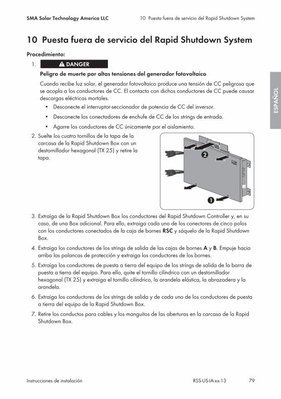
10 Puesta fuera de servicio del Rapid Shutdown SystemProcedimiento:
1.Peligro de muerte por altas tensiones del generador fotovoltaicoCuando recibe luz solar, el generador fotovoltaico produce una tensión de CC peligrosa quese acopla a los conductores de CC. El contacto con dichos conductores de CC puede causardescargas eléctricas mortales.
• Desconecte el interruptor-seccionador de potencia de CC del inversor.• Desconecte los conectadores de enchufe de CC de los strings de entrada.• Agarre los conductores de CC únicamente por el aislamiento.
2. Suelte los cuatro tornillos de la tapa de lacarcasa de la Rapid Shutdown Box con undestornillador hexagonal (TX 25) y retire latapa.
3. Extraiga de la Rapid Shutdown Box los conductores del Rapid Shutdown Controller y, en sucaso, de una Box adicional. Para ello, extraiga cada uno de los conectores de cinco poloscon los conductores conectados de la caja de bornes RSC y sáquelo de la Rapid ShutdownBox.
4. Extraiga los conductores de los strings de salida de las cajas de bornes A y B. Empuje haciaarriba las palancas de protección y extraiga los conductores de los bornes.
5. Extraiga los conductores de puesta a tierra del equipo de los strings de salida de la barra depuesta a tierra del equipo. Para ello, quite el tornillo cilíndrico con un destornilladorhexagonal (TX 25) y extraiga el tornillo cilíndrico, la arandela elástica, la abrazadera y laarandela.
6. Extraiga los conductores de los strings de salida y de cada uno de los conductores de puestaa tierra del equipo de la Rapid Shutdown Box.
7. Retire los conductos para cables y los manguitos de las aberturas en la carcasa de la RapidShutdown Box.
10 Puesta fuera de servicio del Rapid Shutdown SystemSMA Solar Technology America LLC
Instrucciones de instalación 79RSS-US-IA-xx-13
ESPA
ÑO
L
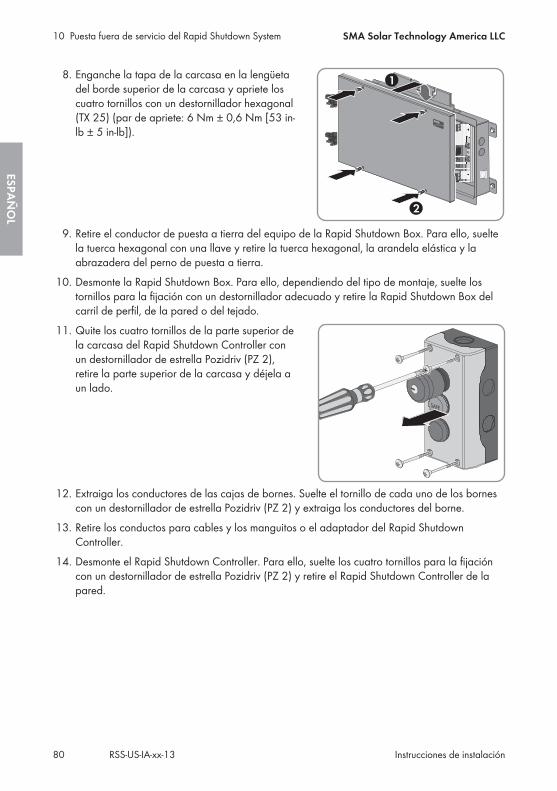
8. Enganche la tapa de la carcasa en la lengüetadel borde superior de la carcasa y apriete loscuatro tornillos con un destornillador hexagonal(TX 25) (par de apriete: 6 Nm ± 0,6 Nm [53 in-lb ± 5 in-lb]).
9. Retire el conductor de puesta a tierra del equipo de la Rapid Shutdown Box. Para ello, sueltela tuerca hexagonal con una llave y retire la tuerca hexagonal, la arandela elástica y laabrazadera del perno de puesta a tierra.
10. Desmonte la Rapid Shutdown Box. Para ello, dependiendo del tipo de montaje, suelte lostornillos para la fijación con un destornillador adecuado y retire la Rapid Shutdown Box delcarril de perfil, de la pared o del tejado.
11. Quite los cuatro tornillos de la parte superior dela carcasa del Rapid Shutdown Controller conun destornillador de estrella Pozidriv (PZ 2),retire la parte superior de la carcasa y déjela aun lado.
12. Extraiga los conductores de las cajas de bornes. Suelte el tornillo de cada uno de los bornescon un destornillador de estrella Pozidriv (PZ 2) y extraiga los conductores del borne.
13. Retire los conductos para cables y los manguitos o el adaptador del Rapid ShutdownController.
14. Desmonte el Rapid Shutdown Controller. Para ello, suelte los cuatro tornillos para la fijacióncon un destornillador de estrella Pozidriv (PZ 2) y retire el Rapid Shutdown Controller de lapared.
10 Puesta fuera de servicio del Rapid Shutdown System SMA Solar Technology America LLC
Instrucciones de instalaciónRSS-US-IA-xx-1380
ESPAÑ
OL
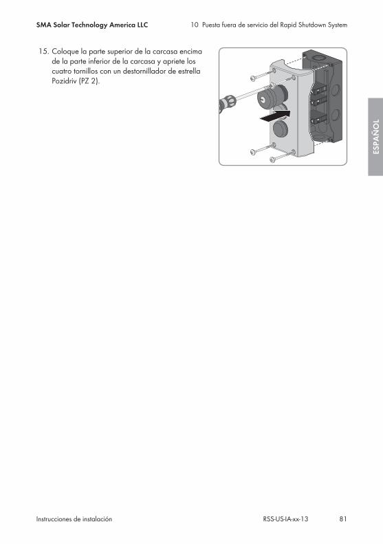
15. Coloque la parte superior de la carcasa encimade la parte inferior de la carcasa y apriete loscuatro tornillos con un destornillador de estrellaPozidriv (PZ 2).
10 Puesta fuera de servicio del Rapid Shutdown SystemSMA Solar Technology America LLC
Instrucciones de instalación 81RSS-US-IA-xx-13
ESPA
ÑO
L
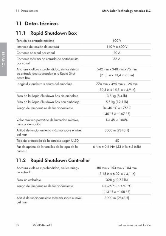
11 Datos técnicos
11.1 Rapid Shutdown BoxTensión de entrada máxima 600 V
Intervalo de tensión de entrada 110 V a 600 V
Corriente nominal por canal 20 A
Corriente máxima de entrada de cortocircuitopor canal
36 A
Anchura x altura x profundidad, sin los stringsde entrada que sobresalen a la Rapid Shut-down Box
542 mm x 340 mm x 75 mm(21,3 in x 13,4 in x 3 in)
Longitud x anchura x altura del embalaje 770 mm x 395 mm x 125 mm(30,3 in x 15,5 in x 4,9 in)
Peso de la Rapid Shutdown Box sin embalaje 3,8 kg (8,4 lb)
Peso de la Rapid Shutdown Box con embalaje 5,5 kg (12,1 lb)
Rango de temperatura de funcionamiento De -40 °C a +75°C(-40 °F a +167 °F)
Valor máximo permitido de humedad relativa,con condensación
De 4% a 100%
Altitud de funcionamiento máxima sobre el niveldel mar
3000 m (9843 ft)
Tipo de protección de la carcasa según UL50 4X
Par de apriete de lo tornillos de la tapa de lacarcasa
6 Nm ± 0,6 Nm (53 in-lb ± 5 in-lb)
11.2 Rapid Shutdown ControllerAnchura x altura x profundidad, sin los stringsde entrada
80 mm x 153 mm x 104 mm(3,15 in x 6,02 in x 4,1 in)
Peso sin embalaje 328 g (0,72 lb)
Rango de temperatura de funcionamiento De -25 °C a +70 °C(-13 °F a +158 °F)
Altitud de funcionamiento máxima sobre el niveldel mar
3000 m (9843 ft)
11 Datos técnicos SMA Solar Technology America LLC
Instrucciones de instalaciónRSS-US-IA-xx-1382
ESPAÑ
OL

Tipo de protección de la carcasa según UL50 4X
Par de apriete de los tornillos de la parte supe-rior de la carcasa
1,8 Nm (16 in-lb)
11 Datos técnicosSMA Solar Technology America LLC
Instrucciones de instalación 83RSS-US-IA-xx-13
ESPA
ÑO
L
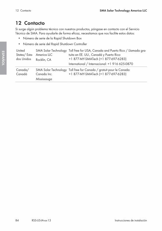
12 ContactoSi surge algún problema técnico con nuestros productos, póngase en contacto con el ServicioTécnico de SMA. Para ayudarle de forma eficaz, necesitamos que nos facilite estos datos:
• Número de serie de la Rapid Shutdown Box• Número de serie del Rapid Shutdown Controller
UnitedStates/ Esta-dos Unidos
SMA Solar TechnologyAmerica LLCRocklin, CA
Toll free for USA, Canada and Puerto Rico / Llamada gra-tuita en EE. UU., Canadá y Puerto Rico:+1 877-MY-SMATech (+1 877-697-6283)International / Internacional: +1 916 625-0870
Canada/Canadá
SMA Solar TechnologyCanada Inc.Mississauga
Toll free for Canada / gratuit pour le Canada:+1 877-MY-SMATech (+1 877-697-6283)
12 Contacto SMA Solar Technology America LLC
Instrucciones de instalaciónRSS-US-IA-xx-1384
ESPAÑ
OL
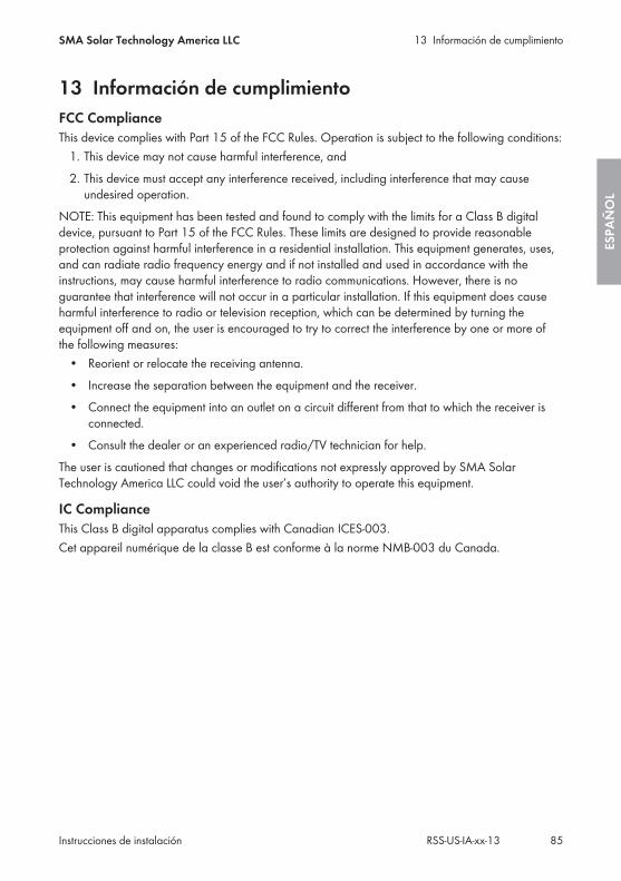
13 Información de cumplimientoFCC ComplianceThis device complies with Part 15 of the FCC Rules. Operation is subject to the following conditions:
1. This device may not cause harmful interference, and2. This device must accept any interference received, including interference that may cause
undesired operation.NOTE: This equipment has been tested and found to comply with the limits for a Class B digitaldevice, pursuant to Part 15 of the FCC Rules. These limits are designed to provide reasonableprotection against harmful interference in a residential installation. This equipment generates, uses,and can radiate radio frequency energy and if not installed and used in accordance with theinstructions, may cause harmful interference to radio communications. However, there is noguarantee that interference will not occur in a particular installation. If this equipment does causeharmful interference to radio or television reception, which can be determined by turning theequipment off and on, the user is encouraged to try to correct the interference by one or more ofthe following measures:
• Reorient or relocate the receiving antenna.• Increase the separation between the equipment and the receiver.• Connect the equipment into an outlet on a circuit different from that to which the receiver is
connected.• Consult the dealer or an experienced radio/TV technician for help.
The user is cautioned that changes or modifications not expressly approved by SMA SolarTechnology America LLC could void the user’s authority to operate this equipment.
IC ComplianceThis Class B digital apparatus complies with Canadian ICES-003.Cet appareil numérique de la classe B est conforme à la norme NMB-003 du Canada.
13 Información de cumplimientoSMA Solar Technology America LLC
Instrucciones de instalación 85RSS-US-IA-xx-13
ESPA
ÑO
L

www.SMA-Solar.com