slurry fracture injection (sfi) zero discharge deep well
TRANSCRIPT

1
Slurry Fracture Injection (SFI)Zero Discharge Deep Well Disposal
Considerations for the Fukushima Daiichi Nuclear Power Plant Site Clean-Up
Terralog Technologies Inc.
Deep Well Disposal Concepts• What is Slurry Fracture Injection (SFI)• Best Practices for Deep Well Disposal • Geology & Technical Aspects of SFI• Zero Discharge Operations
Field Cases• SFI & NORM disposal
Disposal of Waste Streams – Summary
Considerations for the Fukushima Daiichi Nuclear Power Plant Site Clean-Up
Discussion
Terralog Technologies Inc. (“TTI”) is an international environmental services company headquartered in Calgary.
• TTI is a leader in clean-energy geomechanics & deep well disposal technology.
• TTI has developed an innovative, long-term, large volume, sustainable fracturing process - Slurry Fracture Injection (SFI)
SFI with ‘Process Control’
• SFI is an advanced deep well disposal process
TTI’s Slurry Fracture Injection (“SFI”) process is a technology for environmentally sustainable resource management & waste management. SFI disposes of waste streams securely and permanently:
• SFI is a permanent Zero Discharge disposal solution for petroleum industry E&P waste, NORM and contaminated soils
• SFI results in ‘Zero Discharge E&P’ operations
• SFI is viable for many types of waste streams & applications
TTI is currently deploying its SFI technology with projects in USA, SE Asia and the Middle East.
TTI’s Slurry Fracture Injection (“SFI”) is an Environmentally SustainableHF technology. SFI is used as an advanced deep well disposal process:
• Large volume of waste disposal (10,000+ m3/month)
• Disposal of multiple wastes: contaminated soil, oily sludge, NORM, E&P wastes
• Fast implementation allowing for rapid deployment and start-up
• Environmentally sustainable disposal process - Zero Discharge waste management
• Life-cycle cost effectiveness
TTI is the leader in deep well disposal services, with the proven capability to provide the SFI process to clients worldwide.
Significant environmental advantages for SFI as a waste management strategy:
• Process Control systems to mitigate risks (OOZI, loss of wellbore integrity, groundwater impact)
• Permanent disposal: no risk future environmental liabilities
• Zero Discharge: no interaction of disposed waste with the surface biosphere
No ground water contamination, protects soil and air quality
• Disposal operations do not impair surface lands &water resources
• Cost effective and time effective waste disposal.
• Safeguard public health by reducing & removing pollution

2
SFI solves this problem !!!
Deep well disposal: granular/fines or viscous fluid waste streams• Produced solids, granular fines, and oily sludge• These waste streams are slurried into a pumpable slurry
Heavy slurry - Different ‘slurry design’ for different waste-types• 15-25% by volume waste concentration• 1.15-1.3 SG & FV < 60 sec• Waste water is the mix-water
Hydraulic fracturing in ‘soft rock’ - Different strategies for different wastes• Injection rates and pressures ~> FER & FEP• Long-term, continuous - cyclic injection (cycle design is v. important)
Injection of large waste volumes (3,000 -17,000 m3/month)Deep geological sequestration (350-2000m) – ‘Soft Rock’.Multiple waste streamsProcess Control for operational & environmental assuranceExcellent long-term security & Environmental Advantages
TTI’s proprietary SFI technology provides its clients with its zero discharge solutions based on the following four ‘Process Control’ factors:1. Formation Containment.
• TTI’s SFI process guarantees the integrity of containment of the disposed slurry.
2. Optimization Formation Response.• Ensures optimum sustainable pressures
and rates of injection
• Dissipation of stress/pressure gradients.
3. Maximization of Storage Capacity.• With strong backgrounds in geomechanics &
reservoir engineering, TTI maximizes formation storage capacity.
4. Maintenance of Wellbore Integrity.• TTI’s SFI process also ensures mechanical
and hydraulic integrity.
TTI applies the science of geo-mechanics in providing customized, long-term & permanent waste disposal solutions to E&P companies (“Bottoms Up vs. Pump & Pray”).
Day 1
Day 3
Day 2Injection
WellFracture ‘Rotations:
Changes in local stresses cause re-orientation of each new fracture
σ2
σ3
σ2
σ3
Initial Injection Subsequent Injection Fracture Re-orientation
Waste Pod
Fracture: Waste Pod‘Filling’
Fracture: Waste Pod‘Growth’ Fracture: Waste Pod
‘Packing’
Waste Pod Development:Cumulative impact of solids/ waste placement, fluid flow, and fracture rotation is to create a
waste pod’
Volumetric Dilation:Differential pressure & stress changes cause shear
displacement &volume enhancement

3
0
500
1000
1500
2000
2500
3000
3500
4000
9/13/973:00
9/13/975:00
9/13/977:00
9/13/979:00
9/13/9711:00
9/13/9713:00
9/13/9715:00
9/13/9717:00
9/13/9719:00
9/13/9721:00
9/13/9723:00
13-Sep-97
Inje
ctio
n B
otto
m H
ole
Pres
sure
(ps
i)
0
500
1000
1500
2000
2500
3000
3500
4000
9/13/973:00
9/13/975:00
9/13/977:00
9/13/979:00
9/13/9711:00
9/13/9713:00
9/13/9715:00
9/13/9717:00
9/13/9719:00
9/13/9721:00
9/13/9723:00
13-Sep-97
Inje
ctio
n B
otto
m H
ole
Pres
sure
(ps
i) NOW injection period: 4-12hrs/day
shut-in period
start injection
end injection
Daily Pressure vs. Time
0
500
1000
1500
2000
2500
3000
3500
4000
8/30 8/31 9/1 9/2 9/3 9/4 9/5 9/6 9/7 9/8 9/9 9/10 9/11 9/12 9/13 9/14 9/15 9/16 9/17 9/18 9/19 9/20 9/21Date
Inje
ctio
n W
ell B
otto
m H
ole
Pres
sure
(ps
i)
Monthly Injection Cycle
Development of pressure & stress gradientsMultiple closure stressesMultiple flow regimes (linear/radial)Dynamic fracture propagation• fracture geometry, dip, azimuth
Dynamic pressure fall-offsComplex waste pod development
Formation Response = f(slurry composition,operating strategy, lithology, stratigraphy)
Need to ‘Get it Right’
•Very powerful disposal process
• Volumes/waste types/Zero Discharge
•Get it wrong….
• Loss of formation injectivity
• OOZI
• Well bore plugging
• Loss of wellbore integrity
‘Best Practices’ implementation for SFI field operations… to ‘get it right’:
• Formation selection – geology considerations
• Well design
• Injection strategy
• Process monitoring & process control
• Operations management & technical support
• Formation storage capacity & waste pod development
Best Practices are essential for ensuring controlled & successful injection operations

4
TTI Project Development
Prelim SFI Project Estimates
Prelim SFI Project Design &
Recommendations
Disposal Well Design
Slurry Design
Slurry Fracture Mechanics
Waste Material Audit
Phase 1 – Technical Feasibility Study (TFS)
Geological Assessment
Phase 2a – SFI Front End Engineering & Design (FEED)
SFI Project Management
Personnel & Project Management
Support
SFI Engineering Personnel &
Technical Support
Field Operating Personnel
Phase 3 – SFI Field Operations
Entire SDU Equipment System
Phase 2b – Regulatory Approval
Letter of Approval / Project Permit
Liaison with Regulatory Agency & Address Concerns
Comprehensive SFI Project Application
Identify Relevant Government
Regulatory Agency
Field Site Assessment & Location Selection
Formation Testing
SFI Start‐up, Operating Strategies & Emergency
Procedures
SFI Process Control Monitoring Program
Comprehensive SFI Project Implementation Schedule
CAPEX & OPEX Cost Structure
Final SFI Facility Design
Final Process Design Specifications
‘Best Practices’ for Deep Well Disposal mitigates these risks:
Out-Of- Zone-Injection (OOZI)Injected material breaking the permitted intervalInjected fluids to surface
effect on ground water resources
waste breaching to sea floor offshore operations
Off-set well communication and leakageDue to cement or casing impairment
Breach of injection well integrityDue to cement or casing impairment
Injection well performanceFormation backflow and well plugging
Target Zone: main formation selected for injection-disposal operationsTarget Zone should be poorly consolidated and high permeability sand (Soft Rock)High compressibility• Formation yields easily to allow insertion of waste volume
High permeability
• Fluids drain off quickly preventing high pressures which can cause inadvertent fracturing or shearing
• prevents damage to wellbore• reduced potential of uphole fluid migration
In these types of formations the high in situ stresses and the high pressure bleed off capacity of the formation ensures the waste is permanently immobilized.
400-
1000
m
Cased SFI Wells
Sand Fmt.
Fractured Lst Fmt
CONFINING ZONE(Shale)
TARGET ZONE(Sand)
Sand
Shale
SurfaceSediments(Contain Ground-water)
Perforations
Packer
Production Casing 7”
Surface Casing
InjectionTubing 3 1/2 to 4”
Uniform Cement Sheath
Non-contracting, ductile cement. Needs to stand up to high fracture pressures on a daily cyclic basis.
SRO/Computer
Bottomhole pressure sensor
Cable
Underlying Shale
CONTAINMENT ZONE (Sands & Shales)
Ensures wellbore integrity
•Mechanical & hydraulic
No surface and groundwater contamination.
• Multiple barriers to USDW
• Wellbore & geologic barriers
Allows for wellbore monitoring & control
Main Shale Barrier
Confining Zone
Containment Zone
SFI Injection Target Zone
Permitted Intervalfor SFI
5
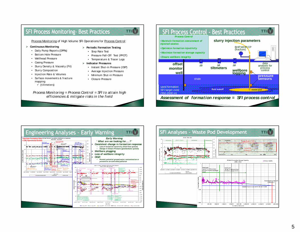
Continuous Monitoring • Daily Pump Reports (DPRs)• Bottom Hole Pressure• Wellhead Pressure• Casing Pressure• Slurry Density & Viscosity (FV)• Slurry Composition• Injection Rate & Volumes• Surface movements & fracture
mapping(tiltmeters)
Periodic Formation Testing• Step Rate Test• Pressure Fall-Off Test (PFOT)• Temperature & Tracer Logs
Indicator Pressures• Instant Shut-in Pressure (ISIP)• Average Injection Pressure• Minimum Shut-in Pressure• Closure Pressure
Process Monitoring = Process Control = SFI to attain high efficiencies & mitigate risks in the field
Process Monitoring of High Volume SFI Operations for Process Control:
waste pod
θ θ θ
slurry injection parameters
ΔθΔθ Δθ
pressure sensors
tiltmetersoffset
monitor well
dataanalysis for
process control
BHP,WHP,CP(fracture)
Assessment of formation response = SFI process control
sand formationSFI target zone(350-2000 m)
shale
fluid leakoff
wellbore logging
Process Control
•Maintain formation containment of injected wastes
•Optimize formation injectivity
•Maximize formation storage capacity
•Ensure wellbore integrity
Injection-Formation Data & SFI Operational Events
Early Warning‘ What are we looking for....? ’
Consistent change in formation response• Loss of formation injectivity (fluid flow system)• Change in Closure Pressure (geomechanic system)
Wellbore pluggingLoss of wellbore integrityOOZI
• Prevent potential ground-water contamination or preventive un-controlled pollution

6
Wellbore integrity
•Mechanical & hydraulic
Assessment process
•Engineering Plots
•Temperature log
•OA log
Usually loss of cement
• Very difficult to remediate.
• Need to ensure good cementing program and cement job during well construction !!!
DON’T save money on the well!!!
Main Shale Barrier
Confining Zone
Containment Zone
SFI Injection Target Zone
Permitted Intervalfor SFI
Slurry Fracture Injection is an ideal solution for permanent & zero discharge disposal of multiple waste streams
MunicipalitiesWastewater treatment sludge
(i.e. Biosolids)Sulfur, fly ash, incinerator residueIndustrial effluent, sludgeOther waste streamsCarbon sequestration (CCS)
Petroleum IndustryDisposal of E&P wastesDrilling wastesOilfield produced solids Oily viscous fluids/sludge NORMTanks bottoms Contaminated soils
NORM Storage & Waste30+ pCi/gm Radium 226/228 (1.5 Bq/gm)
5,000 m3 NORM was not pre-treated prior to injection
7
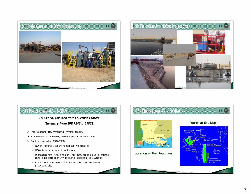
Louisiana, Chevron Port Fourchon Project
(Summary from SPE 71434, 53821)
Port Fourchon, Bay Marchand terminal facility
Processed oil from nearby offshore platforms since 1949
Facility cleaned up 1997-2000:
• NORM: Naturally occurring radioactive material
• NOW: Non-hazardous oilfield waste
• Processing pits: Contained drill cuttings, drilling mud, produced sand, pipe scale (barium/calcium precipitate), oily wastes
• Canal: Sediments were contaminated by overflows from processing pits
Location of Port Fourchon
Fourchon Site Map

8
NORM:
Contamination level
• Maximum ~ 110 pCi/gm Radium 226 (4.1 Bq/gm)
• Average ~ 40 pCi/gm Radium 226 (1.5 Bq/gm)
• U238 and Th 234/Ra 228
Area
• Bay Marchand Terminal: Pits #1, #2, #3 and some land area
• storage pits for drill cuttings, spent drilling fluids, oily waste, pipe scale, etc
Depth of contamination
• Maximum ~ 12 ft ( 3.6 meters)
• Average ~ 8 ft ( 2.4 meters)
PitsPits
Chevron Pipeline CompanyChevron Pipeline Company
WellheadWellhead
Injection Injection FacilitiesFacilities
Dead End Canal
….Before
….During
After….Final closure criteria:• upper 15cm soil < 7 pCi/g Ra226/228
• below 15cm soil ~17pCi/g Ra226/228
• unrestricted land use permitted
SFI Project – Site Remediation
Location Waste Volume (bbls)Bay Marchand Pits
(Oct 1997 – Sept 1998) 371,600
Dead End Canal (Feb 1999 – Mar 2000)
623,100
Other NOW Solids 6,120 Total 1,000,800
(160,000 m3)
Produced Solids (oily contaminated sand)
SDU system
Containment system(Cement pit)
Flowline to SFI well
10,000+ m3/month

9
Duri,Sumatra
PT Terralog Teknologi Indonesia (PT TTI) has been working in Duri, Indonesia for 14 years to dispose of oily sludge & drilling waste from heavy oil production operations. SFI disposal operations are integrated with oil production operations.
Terralog’s Deep Well Disposal Best Practices adopted by the operator.
SFI FacilityDuri Oilfield
Indonesia
Duri SFI Project has disposed of oily sludge & drilling waste from oil production operations (December 2002 – June 2017):~ 1.6 million m3 (10.1 million bbls) ~ 5.9 million m3 (37 million bbls) produced water
July 2003: SFI achieves Zero Discharge of E&P wastes into the environment
In 2016 Terralog achieved 5,000 days ‘Incident & Injury Free’(IIF) and Zero MVA
Production wastes !
Oily sand
Asphaltines
Salts
Heavy Metals
The most common risks/problems effecting overall performance of SFI projects are:Loss of wellbore integrity during injection operations.
• Typically related to poor cementing of the disposal-injection well above the disposal zone.loss of hydraulic integrity
• Injection well collapse/shear above injection formationloss of mechanical integrity
Inter-well communication• Hydraulic communication between injection well and offset well (s)
containment breach due to intersecting nearby poorly cemented wells• Potential for OOZI
Poor well design wrt the waste type, waste volumes to be injected and disposal zone geology.• This factor can results in wellbore plugging and poor formation injectivity.• Potential for wellbore integrity problems & OOZI• DON’T ‘Save’ money on the well…..!!!
Poor geological characterization of the injection zone and target zones.
Poor (or no) integration of geological assessment, well design, slurry design & injection strategy
Poor integration = poor performance…guaranteed !!!

10
1. Use ‘Best Practices’ Workflow.Integration of geology, waste stream, well design, slurry design, & injection strategy
2. Key Process Monitoring Tools:
BHP monitoring at injection wellPump Pressure and WHP are NOT enoughAssess formation response to injection operationsFormation Testing
Evaluate formation flow behavior and in-situ stress:SRT to assess stress state & FEP/FERPressure Fall-off Analyses
Tracer & Temperature LogsEvaluate near-well fluid flow & wellbore integrity
3. Process Control….always!!!Maintaining fracture/waste pod containmentOptimizing formation response ( injectivity & leak-off)Maximizing formation storage capacityEnsure wellbore integrity
Integration of monitoring data =
tracking of injected material in situ &
formation response.No P&P
Ground Water Protection:Geological evaluation and selection
Proper selection of Target, Containment & Confining Zones
Disposal well design & performanceMultiple barriers to uphole fluid movementsVerify wellbore integrity
SFI ops must continually monitor (Process Monitoring):Formation geomechanics & fluid flow responseSlurry design & injection strategyWellbore mechanics/performanceSurface injection operations
Process Control….alwaysMaintaining fracture/waste pod containmentOptimizing formation injectivityMaximizing formation storage capacityEnsure wellbore integrity
TTI
Regulator
Client
Environmental Benefits of SFI
SFI achieves ‘Zero Discharge’ of wastesNo negative biosphere interactionprotection of USDW, soil quality , air qualityprevents surface water and ground water contamination
Does not impair future land use
Protects environmentally sensitive areas
Acceptable to society & communityreduces pollution to safeguard human health
Safe and secure disposal approachNORM wastes are safely sequesteredmultiple waste stream disposal
Efficient & economical waste management strategy
Permanent & secure disposal is best!long-term liability to operator/generator is greatly reduced
…Greater environmental security with SFI
To help Clients achieve Zero Discharge Operations….
Complex Geology:
• Japan is in a subduction zone, sits on top 4 tectonic plates and is in an active crustal movement zone.
• It is in a zone of active seismicity, active faults, and active volcanoes.
• However there are many records of hydraulic fracturing events, as well as geomechanics data.
Some of Japan’s Hydraulic Fracturing Applications:• Hydraulic fracturing operations in geothermal fields including Nigorikawa, Kakkonda, and
Sengan.
• Multi-stage fracturing for stimulation of naturally fractured volcanic rock in Minami-Nagaoka Gas Field.
• Tight shale oil stimulation in Fukumezawa oil field in Akita in 2014-2017.
• No environmental issues were reported.
Carbon Capture & Storage (CCS):
• The Minami-Nagaoka gas field, 10,400 tonnes of CO2 injected in saline aquifer.
• Offshore Tomakomai has suitable geology & is a candidate for CCS.

11
The Futaba fault crushing belt, which is approximately 80 km long, is located 8 km west of the Daiichi
Nuclear Power Station (NPS). Abukuma Mountains, composed of plutonic rocks such as granite, are
west of the crushing belt.
Source: Atsunao Marui, Geomorphology & geology around the Fukushima Daiichi NPS
Source: Sugai, Matsui, 1957
PotentialConfining Zone
Potential Containment
Zone
Permitted Intervalfor SFI
Potential SFITarget Zones
Source: Yanagisawa, et. al., 1989Abukuma metamorphic rocks
Depth ~ 1000m
Depth ~ 750m
Depth ~ 550m
• SFI is well-understood, safe, and suitable for … Water/liquids, fine grained solids, sludge containing radionuclides:
Step 1: Demonstration project for disposal of liquid waste streams
Step 2: Finely ground solids with low levels- after the liquid wastes are shown to be injectable safely
A high degree of containment and safety certainty can be achieved by:
TFS- FEED: Proper choice of the number of wells, the monitoring systems (wells, sensors)…Best Practices for Project Development.
Process Monitoring & Process Control: A staged, well-monitoredprocess starting with demo project for liquid injection & technical review.
Batch injection: Start each waste stream with small batches, in order to assure the design parameters, then larger batches of injection
Controlled Injection: Contaminated liquid injection in a “continuous” mode
Then, consideration of small batches of low solids content slurry interspersed between liquid injection
Progressive development approach: Never moving to the next stage without confidence based on the on-going stages and data collection and analyses.
• Technical Committee Oversight – from Stakeholders

12
• The sedimentary basin is favorable because of… Suitable layered sand/shale strata leading to lateral flow, not vertical flow.
Sediments are ductile, especially the high-porosity clayey strata, not susceptible to brittle fractureAny “down-to-the-sea” listric faults are likely sealing faults
High gradients that are “to the sea” because of the proximity of the hills to the west that give high elevation recharge .Presence of significant storage capacity because of good porosity in the potential disposal zones
The large pore volumes, accompanied by high rock compressibility, mean that the system has capacity to take and store slurried wastes streams.
Relatively strong deep regional flow in the easterly direction (seaward).Natural flow dispersion and dilution help the process, always reducing the concentration along the flow pathThe liquids are retained in the sediments for many kilometers eastward, the deep waters do not interact with the shallow groundwater systemsThe efflux is under the ocean
Extensive presence of clays and adsorptive minerals are found throughout the sedimentary column.These adsorb radioactive cations very effectivelyThe volume of adsorbent minerals is very large, so adsorption capacity is high Radioactive dissolved constituents are immobilized and retained at depth where they can decay safely…and any radioactive species that has not been adsorbed will decay or be diluted to almost background conditions over timeThe cations are adsorbed permanently, the release of any significant quantity of the adsorbed cations is geochemically unlikely.
• Induced Seismicity – What is the chance of increasing the risk of large-scale seismicity? Pressures will be shown to dissipate rapidly so there is minimal risk of large-scale pressurization & stress development of the sediments.There are likely no additional “loads” (stresses) being placed on the dangerous distant fault lines
The dangerous fault lines are many kilometers distant and deep, so the injection activity is not capable of interacting with the seismic sources
There is likely no significant seismicity arising in the soft ductile sediments of the sedimentary wedge in from of Fukushima Daiichi.The stimulated rock volume that SFI is affecting will be small in relationship to faulting and to the volume of sediments in the sedimentary basin .The sediments into which injection would take place are ductile .
Sediments cannot store strain energy in sufficient amounts to generate appreciable levels of seismicity
• The geological, hydrogeological, geomechanics, and geophysics conditions of the Fukushima project are likely suitable for the SFI process to be tested & implemented.
Need to follow SFI project development Best Practices & Stakeholder technical support to verify
• Considerations for moving forward:Verify that SFI deep well disposal is ‘conceptually viable’ under the conditions at Fukushima.SFI can be done as safely as required by any regulator .
TTI has the expertise…. +20 years of SFI project design and field experience.Important to ensure Best Practices for positive outcomes
SFI must be done with all of the monitoring tools and management tools that TTI has developed over decades of advanced deep well disposal field operations.TTI can work with project stakeholders to design a facility that will be safe in all aspects.Process monitoring can be implemented to the degree required…
Extensive arrays of monitor wellbores, upstream and downstreamMicroseismic arrayIndividual injection wellbores are installed with pressure and temperature monitoring systemsAll aspects of the surface activities are fully monitored by flow meters, radioactivity sensors, vibration devices, T, P, density, etc. - can be easily implemented to increase the level of containment assurance
High safety level training and QA/QC system for all workers is important for handling Fukushima waste streams and for SFI operations.
TTI has a very strong record in terms of QHSE standards for SFI operations
Thank-you for your attention
Mr. Roman Bilak, President
Terralog Technologies Inc. (TTI)