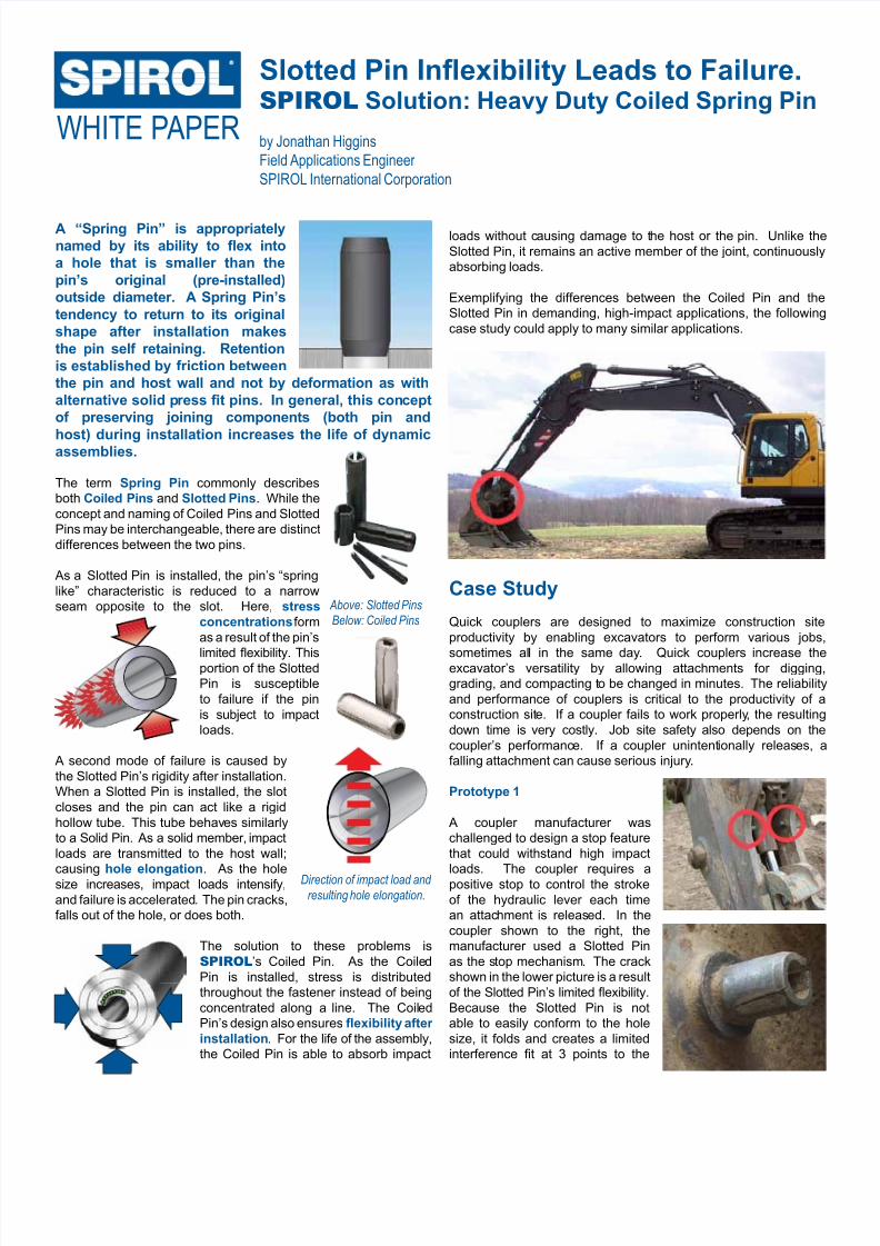
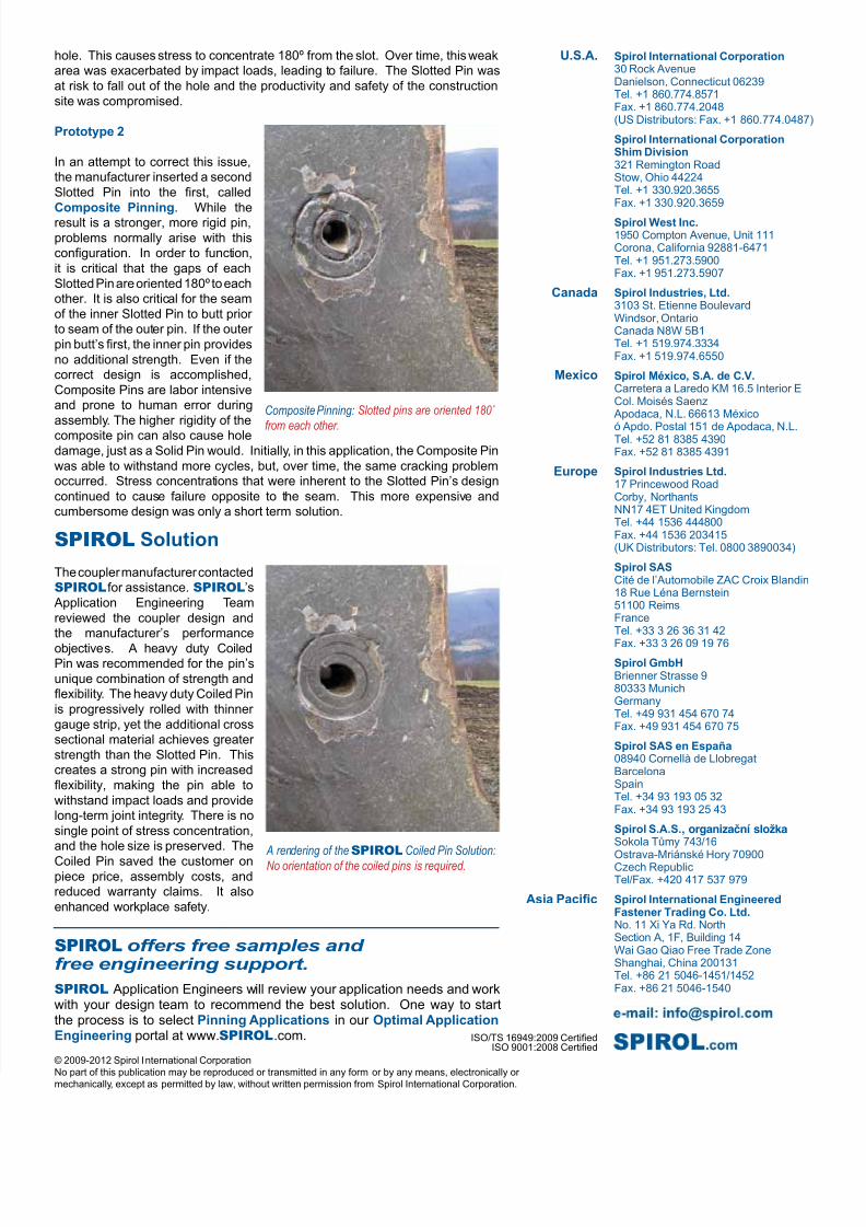
Slotted Pin Inexibility Leads to Failure. SPIROLSolution: Heavy Duty Coiled Spring Pin by Jonathan Higgins Field Applications EngineerSPIROL International Corporation WHITE P APER A “Spring Pin” is appropriately named by its ability to ex into a hole that is smaller than the pin’s original (pre-installed) outside diameter. A Spring Pin’s tendency to return to its original shape after installation makes the pin self retaining. Retention is established by friction between the pin and host wall and not by deformation as with alternative solid p ress t pins. In general, this con cept of preserving joining components (both pin and host) during installation increases the life of dynamic assemblies. The term Spring Pincommonly describes both Coiled Pinsand Slotted Pins. While the concept and naming of Coiled Pins and Slotted Pins may be interchangeable, there are distinct differences between the two pins. As a Slotted Pin is installed, the pin’s “spring like” characteristic is reduced to a narrow seam opposite to the slot. Here, stress concentrations form as a result of the pin’s limited exibility. This portion of the Slotted Pin is susceptible to failure if the pin is subject to impact loads. A second mode of failure is caused by the Slotted Pin’s rigidity after installation. When a Slotted Pin is installed, the slot closes and the pin can act like a rigid hollow tube. This tube behav es similarly to a Solid Pin. As a solid member, impact loads are transmitted to the host wall; causinghole elongation. As the hole size increases, impact loads intensify, and failure is accelerated. The pin cracks, falls out of the hole, or does both. The solution to these problems is SPIROL’s Coiled Pin. As the Coile d Pin is installed, stress is distributed throughout the fastener instead of being concentrated along a line. The Coil ed Pin’s design also ensures exibility after installation. For the life of the assembly, the Coiled Pin is able to absorb impact Above: Slotted Pins Below: Coiled Pins loads without c ausing damage to t he host or the pin. Unlike the Slotted Pin, it remains an active member of the joint, continuously absorbing loads. Exemplifying the differences between the Coiled Pin and the Slotted Pin in demanding, high-impact applications, the following case study could apply to many similar applications. Case Study Quick couplers are designed to maximize construction site productivity by enabling excavators to perform various jobs, sometimes all in the same day . Quick couplers increase the excavator’s versatility by allowing attachments for digging, grading, and compacting t o be changed in minutes. The reliability and performance of couplers is critical to the productivity of a construction sit e. If a coupler fails to work properly , the resulting down time is very costly. Job site safety also depends on the coupler’s performanc e. If a coupler unintent ionally releas es, a falling attachment can cause serious injury. Prototype 1 A coupler manufacturer was challenged to design a stop feature that could withstand high impact loads. The coupler requires a positive stop to control the stroke of the hydraulic lever each time an attac hment is releas ed. In the coupler shown to the right, the manufacturer used a Slotted Pin as the s top mechanism. The crack shown in the lower picture is a result of the Slotted Pin’s limited exibility. Because the Slotted Pin is not able to easily conform to the hole size, it folds and creates a limited interference t at 3 points to the Direction of impact load and resulting hole elongation.