slot-type photomicrosensor with connector or pre-wired
TRANSCRIPT

4
Slot-type Photomicrosensor with connector or pre-wired models (Non-modulated) *1
EE-SX47/67Global Standard Slot-type photomicrosensors with 50- to 100-mA direct switching capacity for built-in application.■ Series includes models that enable switching between
dark-ON and light-ON operation.■ Response frequency as high as 1 kHz.■ Easy operation monitoring with bright light indicator.■ Wide operating voltage range: 5 to 24 VDC■ Models in which the light indicator turns ON for dark-ON
operation are also available.■ A wide range of variations in eight different shapes.■ Flexible robot cable is provided as a standard feature. *2
*1. Only the EE-SX67 Series has pre-wired models.*2. Only for Pre-wired Models.
Be sure to read Safety Precautions on page 8.
Ordering Information
Connector models
*3. These models can be used as Light-ON when the L terminal and positive (+) terminal are connected to each other. To use them as Dark-ON, do not connect these terminals to each other. When used at light-ON, it is useful to select the connector EE-1001-1. The L terminal and positive (+) terminal of this connector are short-circuited in advance.
Appearance Sensingmethod
Connect-ing method Sensing distance Output
configuration Indicator modeModel
NPN output PNP output
Through-beam type
(with slot)
Connector (4 poles)
Dark-ON/Light-ON(selectable) *3
Incident light EE-SX670 EE-SX670P
No incident light EE-SX670A EE-SX670R
Light-ON Incident light EE-SX470 EE-SX470P
Dark-ON/Light-ON(selectable) *3
Incident light EE-SX671 EE-SX671P
No incident light EE-SX671A EE-SX671R
Light-ON Incident light EE-SX471 EE-SX471P
Dark-ON/Light-ON(selectable) *3
Incident light EE-SX672 EE-SX672P
No incident light EE-SX672A EE-SX672R
Light-ON Incident light EE-SX472 EE-SX472P
Dark-ON/Light-ON(selectable) *3
Incident light EE-SX673 EE-SX673P
No incident light EE-SX673A EE-SX673R
Light-ON Incident light EE-SX473 EE-SX473P
Dark-ON/Light-ON(selectable) *3
Incident light EE-SX674 EE-SX674P
No incident light EE-SX674A EE-SX674R
Light-ON Incident light EE-SX474 EE-SX474P
Dark-ON/Light-ON(selectable) *3 Incident light EE-SX675 EE-SX675P
Dark-ON/Light-ON(selectable) *3 Incident light EE-SX676 EE-SX676P
Dark-ON/Light-ON(selectable) *3 Incident light EE-SX677 EE-SX677P
Infrared light
Standard
5 mm(slot width)
L-shaped
T-shaped
Close-mounting
Close-mounting
T-shaped, slot center: 10 mm
F-shaped
R-shaped
EE-SX47/67
5
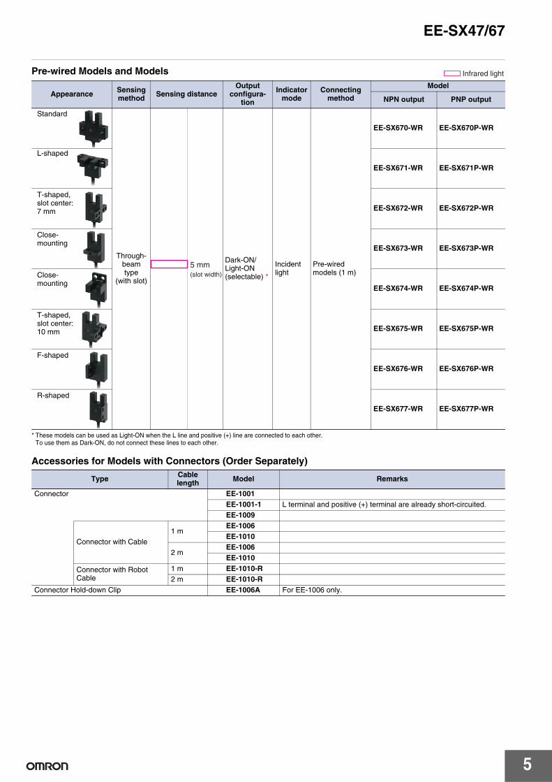
Pre-wired Models and Models
* These models can be used as Light-ON when the L line and positive (+) line are connected to each other. To use them as Dark-ON, do not connect these lines to each other.
Accessories for Models with Connectors (Order Separately)
Appearance Sensingmethod Sensing distance
Output configura-
tion
Indicator mode
Connecting method
Model
NPN output PNP output
Through-beam type
(with slot)
Dark-ON/Light-ON(selectable) *
Incident light
Pre-wired models (1 m)
EE-SX670-WR EE-SX670P-WR
EE-SX671-WR EE-SX671P-WR
EE-SX672-WR EE-SX672P-WR
EE-SX673-WR EE-SX673P-WR
EE-SX674-WR EE-SX674P-WR
EE-SX675-WR EE-SX675P-WR
EE-SX676-WR EE-SX676P-WR
EE-SX677-WR EE-SX677P-WR
Infrared light
Standard
5 mm(slot width)
L-shaped
T-shaped, slot center: 7 mm
Close-mounting
Close-mounting
T-shaped, slot center: 10 mm
F-shaped
R-shaped
Type Cable length Model Remarks
Connector EE-1001EE-1001-1 L terminal and positive (+) terminal are already short-circuited.EE-1009
Connector with Cable1 m
EE-1006 EE-1010
2 mEE-1006 EE-1010
Connector with Robot Cable
1 m EE-1010-R2 m EE-1010-R
Connector Hold-down Clip EE-1006A For EE-1006 only.

6
EE-SX47/67Ratings and Specifications
*1. The indicator is a GaP red LED (peak wavelength: 690 nm).*2. The response frequency was measured by detecting the rotating disk
shown at the right.
Item
Type Standard L-shaped T-shaped, slot center: 7 mm Close-mounting T-shaped, slot
center: 10 mm F-shaped R-shaped
NPN mod-els
ConnectorEE-SX670EE-SX670AEE-SX470
EE-SX671EE-SX671AEE-SX471
EE-SX672EE-SX672AEE-SX472
EE-SX673EE-SX673AEE-SX473
EE-SX674EE-SX674AEE-SX474
EE-SX675 EE-SX676 EE-SX677
Pre-wired models
EE-SX670-WR
EE-SX671-WR
EE-SX672-WR
EE-SX673-WR
EE-SX674-WR
EE-SX675-WR
EE-SX676-WR
EE-SX677-WR
PNP mod-els
ConnectorEE-SX670PEE-SX670REE-SX470P
EE-SX671PEE-SX671REE-SX471P
EE-SX672PEE-SX672REE-SX472P
EE-SX673PEE-SX673REE-SX473P
EE-SX674PEE-SX674REE-SX474P
EE-SX675P EE-SX676P EE-SX677P
Pre-wired models
EE-SX670P-WR
EE-SX671P-WR
EE-SX672P-WR
EE-SX673P-WR
EE-SX674P-WR
EE-SX675P-WR
EE-SX676P-WR
EE-SX677P-WR
Sensing distance 5 mm (slot width)Sensing object Opaque: 2 × 0.8 mm min.Differential distance 0.025 mmLight source GaAs infrared LED with a peak wavelength of 940 nmIndicator *1 Light indicator (red) (turns ON when light is interrupted for models with A or R suffix)Supply voltage 5 to 24 VDC ±10%, ripple (p-p): 10% max.Current consumption 35 mA max. (NPN models), 30 mA max. (PNP models)
Control output
NPN open collector: 5 to 24 VDC, 100 mA max.100 mA load current with a residual voltage of 0.8 V max.40 mA load current with a residual voltage of 0.4 V max.
PNP open collector: 5 to 24 VDC, 50 mA max.50 mA load current with a residual voltage of 1.3 V max.
Response frequency *2 1 kHz min. (3 kHz average)Ambient illumination 1,000 lx max. with fluorescent light on the surface of the receiver.Ambient temperature range Operating: −25 to +55°C, Storage: −30 to +80°CAmbient humidity range Operating: 5% to 85%, Storage: 5% to 95%
Vibration resistance Destruction: 20 to 2,000 Hz (peak acceleration: 100 m/s2)1.5-mm double amplitude for 2 h (4-min periods) each in X, Y, and Z directions
Shock resistance Destruction: 500 m/s2 for 3 times each in X, Y, and Z directionsEnclosure rating IEC60529 IP50Connecting method Special connectors (direct soldering possible), Pre-wired models (Standard cable length: 1 m)Weight(pack-aged)
Connector Approx. 3.1 g Approx. 3 g Approx. 2.4 g Approx. 2.3 g Approx. 3 g Approx. 2.7 g Approx. 2.2 g Approx. 2.2 gPre-wired models Approx. 18.9 g Approx. 17.3 g Approx. 17.8 g Approx. 16.8 g Approx. 17.1 g Approx. 18.3 g Approx. 16.9 g Approx. 16.9 g
Ma-terial
Case Polybutylene phthalate (PBT)Cover emitter/receiver Polycarbonate
Disk
1 mm1 mm2.1 mm
t = 0.2 mm
EE-SX47/67
7
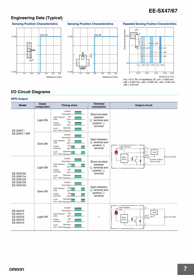
Engineering Data (Typical)
I/O Circuit Diagrams
NPN Output
Sensing Position Characteristics Sensing Position Characteristics Repeated Sensing Position Characteristics
Tr ON
Tr OFF0 1.0 2.0 3.0 4.0 5.0 6.0
Distance d (mm)
Dark-ON
d
Tr ON
Tr OFF0 1.0 2.0 3.0 4.0 5.0 6.0
Distance d (mm)
Dark-ON
d
d
OFF
ON
0 3.00 3.02 3.04 3.06 3.08
Out
put l
evel
tran
sist
or
Distance d (mm)
Ta = −25°C Ta = 55°C Ta = 25°C
Δd3 Δd1
Δd2
Δd4
Δd5
Vcc =12 V, No. of repetitions: 20, Δd1 = 0.002 mm, Δd2 = 0.004 mm, Δd3 = 0.005 mm, Δd4 = 0.02 mm, Δd5 = 0.04 mm
Model Output configuration Timing chart Terminal
connection Output circuit
EE-SX67@EE-SX67@-WR
Light-ON
Short-circuited between
terminal and positive
terminal
Dark-ON
Open between terminal and positive
terminal
EE-SX670AEE-SX671AEE-SX672AEE-SX673AEE-SX674A
Light-ON
Short-circuited between
terminal and positive
terminal
Dark-ON
Open between terminal and positive
terminal
EE-SX470EE-SX471EE-SX472EE-SX473EE-SX474
Light-ON ---
Incident
Interrupted
ON
OFF
ON
OFF
Operates
Releases
Light indicator(red)
Outputtransistor
Load(e.g., relay)
L
Main circuit (Control output)
100 mA max.
5 to 24 VDC
L
OUTIC
1
2
3
4
Light indicator(red)
Load
Incident
Interrupted
ON
OFF
ON
OFF
Operates
Releases
Light indicator(red)
Outputtransistor
Load(e.g., relay)
L
Incident
Interrupted
ON
OFF
ON
OFF
Operates
Releases
Light indicator(red)
Output transistor
Load(e.g., relay)
L
Incident
Interrupted
ON
OFF
ON
OFF
Operates
Releases
Light indicator(red)
Outputtransistor
Load(e.g., relay)
L
Incident
Interrupted
ON
OFF
ON
OFF
Operates
Releases
Light indicator(red)
Outputtransistor
Load(e.g., relay)
5 to 24 VDCIC
OUT
Light indicator(red)
Load
Main circuit

8
EE-SX47/67
PNP Output
Safety Precautions
Refer to Warranty and Limitations of Liability.
This product is not designed or rated for ensuring safety of persons either directly or indirectly.Do not use it for such purposes.
● Operating EnvironmentThese Photomicrosensors have an IP50 (conforms to IEC60529) enclosure and do not have a water-proof or dust-proof structure. Therefore, do not use them in applications in which the sensor will be subjected to splashes from water, oil, or any other liquid. Liquid entering the Sensor may result in malfunction.
Make sure that this product is used within the rated ambient environment conditions.● Installation• When direct soldering to the terminals, use the following guidelines.
Soldering Conditions
• The terminal base uses a polycarbonate resin, which could be deformed by excessive soldering heat, resulting in damage to the product's functionality.
Model Output configuration Timing chart Terminal
connection Output circuit
EE-SX67@PEE-SX67@P-WR
Light-ON
Short-circuited between
terminal and positive
terminal
Dark-ON
Open between terminal and positive
terminal
EE-SX670REE-SX671REE-SX672REE-SX673REE-SX674R
Light-ON
Short-circuited between
terminal and positive
terminal
Dark-ON
Open between terminal and positive
terminal
EE-SX470PEE-SX471PEE-SX472PEE-SX473PEE-SX474P
Light-ON ---
Incident
Interrupted
ON
OFF
ON
OFF
Operates
Releases
Light indicator(red)
Outputtransistor
Load(e.g., relay)
L
L
OUTIC
1
2
4
3
Light indicator (red)
Main circuit
5 to 24 VDC
Load
Incident
Interrupted
ON
OFF
ON
OFF
Operates
Releases
Light indicator(red)
Outputtransistor
Load(e.g., relay)
L
Incident
Interrupted
ON
OFF
ON
OFF
Operates
Releases
Light indicator(red)
Output transistor
Load(e.g., relay)
L
Incident
Interrupted
ON
OFF
ON
OFF
Operates
Releases
Light indicator(red)
Outputtransistor
Load(e.g., relay)
L
Incident
Interrupted
ON
OFF
ON
OFF
Operates
Releases
Light indicator(red)
Outputtransistor
Load(e.g., relay)
5 to 24 VDC
Load
Main circuit
OUTIC
Light indicator (red)
WARNING
Precautions for Safe Use
Precautions for Correct Use
Item Temper-ature
Permissible time Remarks
Solderingiron
350°Cmax.
3 smax.
The portion between the base of the terminals and the position 1.5 mm from the terminal base must not be soldered.
EE-SX670
376d
EE-SX@70@
Lot number and factory code
Model number In the right illustration, 376d indicates the lot number and factory where the product was manufactured. Do not include this code with the model number when ordering.
● Lot Numbers and Models

EE-SX47/67
9
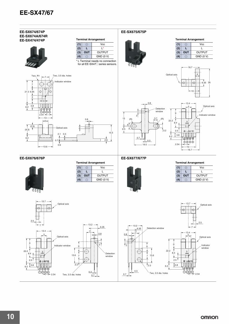
Dimensions (Unit: mm)
Sensors
EE-SX670/670PEE-SX670A/670REE-SX470/470P
19
13.4
5
13.8
9
13.2
6.2
5.5
3.8
2.54
25.4
19
6.95
6.4
0.8
2
0.3 0.732 41
2.53
8.4
Two, 3.2 dia. holes
Four, R1
Optical axis
Two, 3.8 dia. holes
Indicator window
Terminal Arrangement
* L Terminal needs no connection for all EE-SX47@ series sensors.
(1) Vcc
(2) L L*
(3) OUT OUTPUT
(4) GND (0 V)
EE-SX671/671PEE-SX671A/671REE-SX471/471P
19
19
26.2
13.4
13
13.4
5
13
9
2.54
3
14.5
6.2
8.3
7.2
3.2
3
3.8
9
3.6
2.1
0.76.2
0.6
0.3
2
7.2
15.5
0.8
6.95
6.35
32 41
Four, R1
Four, R2
Indicator window
Optical axisTwo, 3.2 dia. holes
Terminal Arrangement
* L Terminal needs no connection for all EE-SX47@ series sensors.
(1) Vcc
(2) L L*
(3) OUT OUTPUT
(4) GND (0 V)
EE-SX672/672PEE-SX672A/672REE-SX472/472P
19
13.4
5
13.7
3
13
2.54
22.2
6.2
6.3
9
6.4
3.8
2
13
0.8
2.5
4.3
0.3 0.72 31 4
7
2.5
38.4
6.2
6.3
26 12.6
Four, R1
Four, R1.6
Indicator window
Optical axis
Terminal Arrangement
* L Terminal needs no connection for all EE-SX47@ series sensors.
(1) Vcc
(2) L L*
(3) OUT OUTPUT
(4) GND (0 V)
EE-SX673/673PEE-SX673A/673REE-SX473/473P
Terminal Arrangement
* L Terminal needs no connection for all EE-SX47@ series sensors.
(1) Vcc
(2) L L*
(3) OUT OUTPUT
(4) GND (0 V)
13.4
5
7
2.54
22.2
6.2
9
12.8
6.3
3.5(6.65)
14.4
3.8
2.8
4.9
2
0.8
0.3 0.732 41
Two, R1 Two, 3.2 dia. holes
Indicator window
Optical axis
10
EE-SX47/67
EE-SX674/674PEE-SX674A/674REE-SX474/474P Terminal Arrangement
* L Terminal needs no connection for all EE-SX47@ series sensors.
(1) Vcc
(2) L L*
(3) OUT OUTPUT
(4) GND (0 V)
7
13.6
513
2.54
3
21.5
6.2
(9.3)
6.2
6.95
7
3
3.8
(2.9)
2.1
0.7
0.6
0.3
2
2.6
15.5
0.8
32 41
Two, R1 Two, 3.5 dia. holes
Indicator window
Optical axis
EE-SX675/675P
Terminal Arrangement
(1) Vcc
(2) L L
(3) OUT OUTPUT
(4) GND (0 V)
5
13.4
16.7
4
26
38.4
2.5
(R)(R)
3.2
3.7
0.8
213
19.5
0.30.7
6.3
6
10
6.35
Indicator window
Optical axis
Optical axis
Detection window
2 31 4
16.713
2.54
22.2
9
6.23.8
EE-SX676/676PTerminal Arrangement
(1) Vcc
(2) L L
(3) OUT OUTPUT
(4) GND (0 V)
2.5
5
8.43
3.8
2.5
6.3513.2
0.8
9
7
0.3
3.3
2
0.7
13.6
7
2.5432 41
13.7
7
13.4
9
22.2
6.2
Indicator window
Optical axis
Optical axis
Detection window
Two, 3.5 dia. holes
EE-SX677/677PTerminal Arrangement
(1) Vcc
(2) L L
(3) OUT OUTPUT
(4) GND (0 V)
2.5
7
13.4
22.2
6.2 3.8
13.26.35
70.8
2
13.6
9
7
3.3
0.3
0.7
13.7
5
2.5
8.43
9
2.5432 41
Detection window
Two, 3.5 dia. holes
Indicator window
Optical axis
Optical axis
EE-SX47/67
11
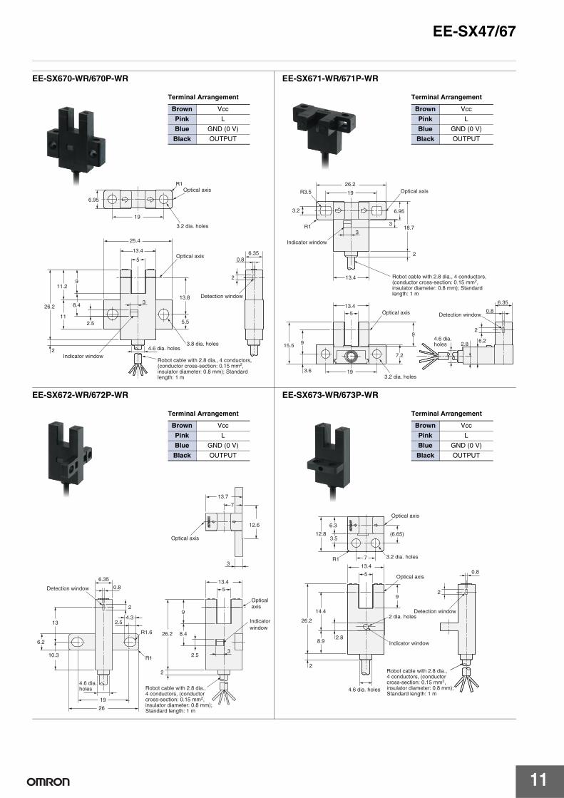
EE-SX670-WR/670P-WR
Terminal Arrangement
Brown Vcc
Pink L
Blue GND (0 V)
Black OUTPUT
R1
19
25.4
6.35
6.95
26.2
2
2.5
13.8
11
8.4
911.2
13.4
5 0.8
5.5
3
2
Optical axis
3.2 dia. holes
Optical axis
Indicator window
3.8 dia. holes4.6 dia. holes
Detection window
Robot cable with 2.8 dia., 4 conductors, (conductor cross-section: 0.15 mm2, insulator diameter: 0.8 mm); Standard length: 1 m
EE-SX671-WR/671P-WR
Terminal Arrangement
Brown Vcc
Pink L
Blue GND (0 V)
Black OUTPUT
26.2
19
6.95
18.73
13.4
13.45
3
9
9
3.6
6.35
0.8
2
6.22.8
3.2
R3.5
R1
15.5
19
7.2
2
Indicator window
Optical axis
Optical axis Detection window
4.6 dia. holes
3.2 dia. holes
Robot cable with 2.8 dia., 4 conductors, (conductor cross-section: 0.15 mm2, insulator diameter: 0.8 mm); Standard length: 1 m
EE-SX672-WR/672P-WR
Terminal Arrangement
Brown Vcc
Pink L
Blue GND (0 V)
Black OUTPUT
13.7
7
12.6
13.45
3
9
2.5
8.426.2
2
26
19
10.3
6.2
13
6.35
0.8
2
4.32.5
R1.6
R13
Indicator window
Optical axis
Detection window
Optical axis
4.6 dia. holes Robot cable with 2.8 dia.,
4 conductors, (conductor cross-section: 0.15 mm2, insulator diameter: 0.8 mm); Standard length: 1 m
EE-SX673-WR/673P-WR
Terminal Arrangement
Brown Vcc
Pink L
Blue GND (0 V)
Black OUTPUT
(6.65)
6.3
14.4
8.9
92
26.2
2
12.8
2.8
3.5
R1
0.813.4
5
7
Optical axis
Optical axis
3.2 dia. holes
Detection window
Indicator window
2 dia. holes
4.6 dia. holes
Robot cable with 2.8 dia., 4 conductors, (conductor cross-section: 0.15 mm2, insulator diameter: 0.8 mm); Standard length: 1 m
12
EE-SX47/67
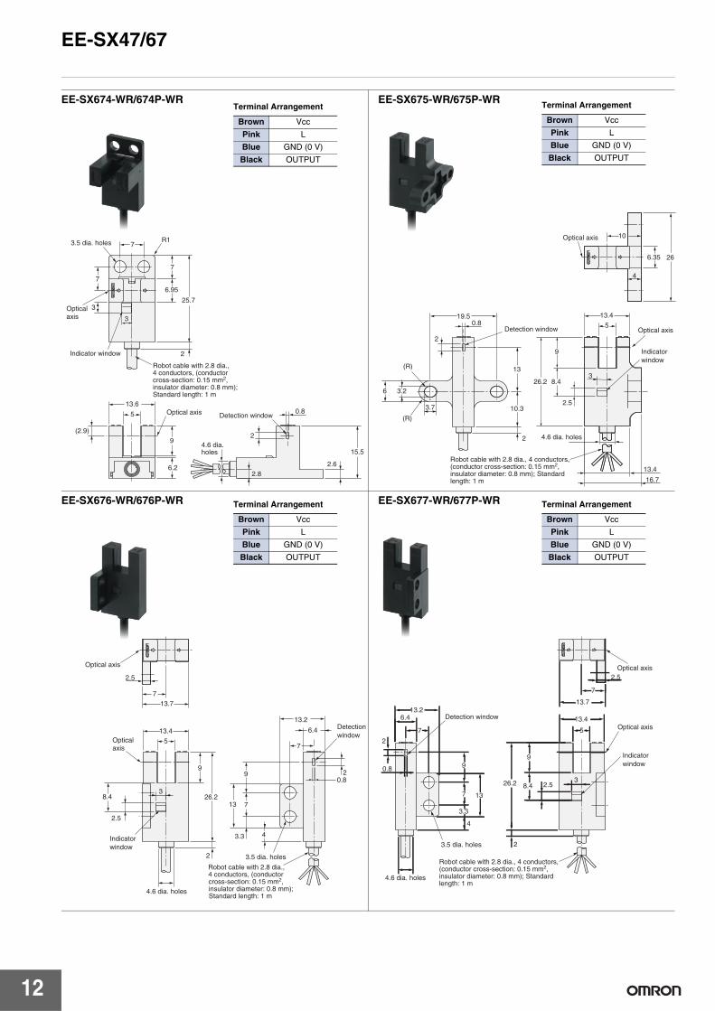
EE-SX674-WR/674P-WRTerminal Arrangement
Brown Vcc
Pink L
Blue GND (0 V)
Black OUTPUT
7
7R1
25.7
6.95
3
3
2
13.6
5
(2.9)
9
6.22.8
2
0.8
2.6
15.5
7
3.5 dia. holes
Indicator window
Optical axis
Detection windowOptical axis
4.6 dia. holes
Robot cable with 2.8 dia., 4 conductors, (conductor cross-section: 0.15 mm2, insulator diameter: 0.8 mm); Standard length: 1 m
EE-SX675-WR/675P-WR Terminal Arrangement
Brown Vcc
Pink L
Blue GND (0 V)
Black OUTPUT
2
3.7
(R)
(R)
6 3.2
13
10.3
2
19.5
16.7
13.4
326.2 8.4
9
2.5
13.4
5
10
4
6.35 26
0.8
Optical axis
Detection window
Indicator window
Optical axis
4.6 dia. holes
Robot cable with 2.8 dia., 4 conductors, (conductor cross-section: 0.15 mm2, insulator diameter: 0.8 mm); Standard length: 1 m
EE-SX676-WR/676P-WR Terminal Arrangement
Brown Vcc
Pink L
Blue GND (0 V)
Black OUTPUT
3
2.5
Indicator window
8.4
2
26.2
9
13.4
5
13.7
7
6.4
13.2
7
20.8
9
713
3.3
2.5
4
Optical axis
Detection window
3.5 dia. holes
Optical axis
4.6 dia. holes
Robot cable with 2.8 dia., 4 conductors, (conductor cross-section: 0.15 mm2, insulator diameter: 0.8 mm); Standard length: 1 m
EE-SX677-WR/677P-WR Terminal Arrangement
Brown Vcc
Pink L
Blue GND (0 V)
Black OUTPUT
3.3
4
7
9
7
6.413.2
13
2
26.2 8.4 2.5
9
13.4
5
13.7
7
2.5
3
2
0.8
Optical axis
Optical axis
Indicator window
3.5 dia. holes
4.6 dia. holes
Detection window
Robot cable with 2.8 dia., 4 conductors, (conductor cross-section: 0.15 mm2, insulator diameter: 0.8 mm); Standard length: 1 m
EE-SX47/67
13
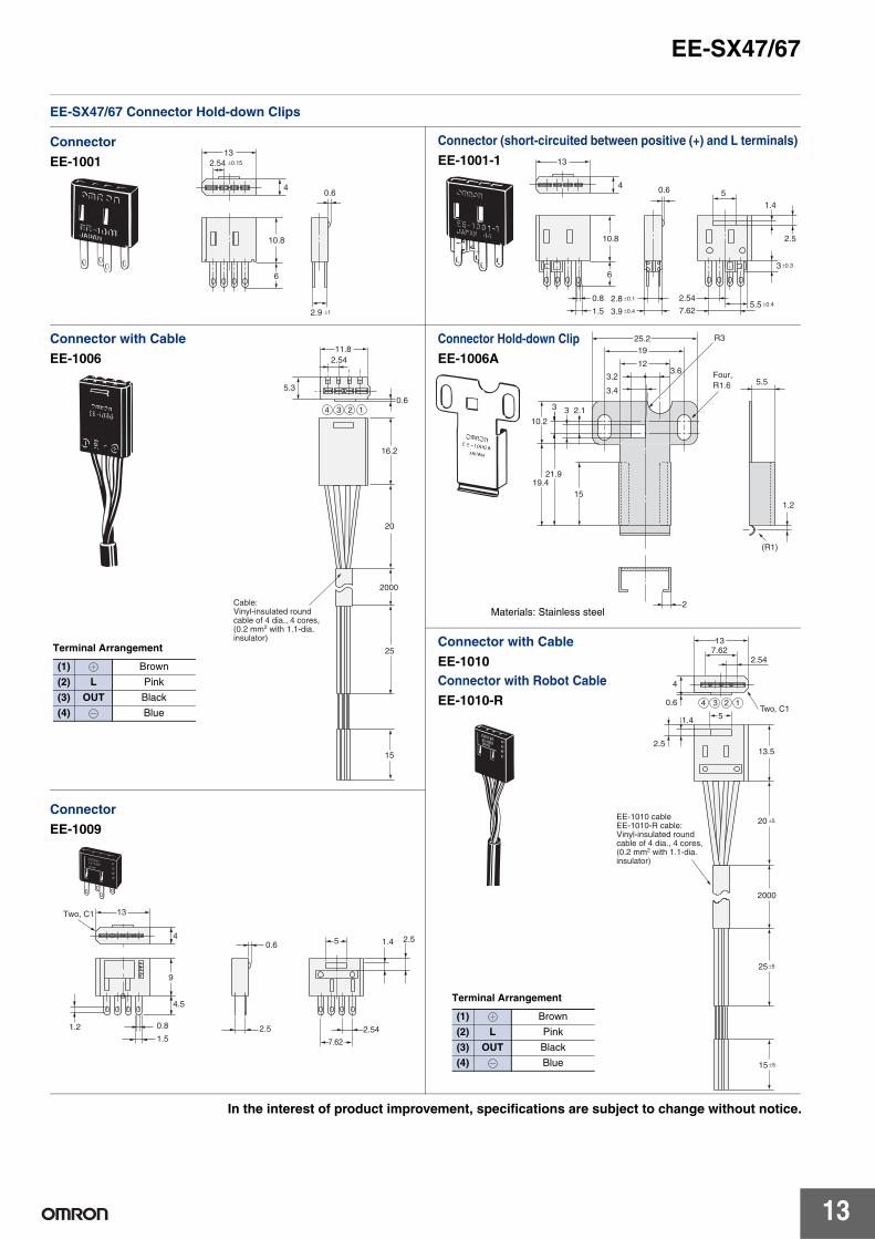
EE-SX47/67 Connector Hold-down Clips
Connector
EE-100113
4
2.54 ±0.15
2.9 ±1
0.6
10.8
6
Connector (short-circuited between positive (+) and L terminals)
EE-1001-1
3.9 ±0.4
2.8 ±0.1
0.6
10.8
6
5
1.5
0.8
13
4
1.4
2.5
3 ±0.3
7.62
2.545.5 ±0.4
11.8
5.3
2.54
0.6
16.2
20
2000
25
15
3 24 1
Cable:Vinyl-insulated round cable of 4 dia., 4 cores, (0.2 mm2 with 1.1-dia. insulator)
Connector with Cable
EE-1006
Terminal Arrangement
(1) Brown
(2) L Pink
(3) OUT Black
(4) Blue
1.2
(R1)
2
5.5
R3
10.2
19.421.9
15
25.219
12
3.2
2.133
3.6
3.4
Four, R1.6
Connector Hold-down Clip
EE-1006A
Materials: Stainless steel
Connector with Cable
EE-1010Connector with Robot Cable
EE-1010-R 0.6
4
2.547.6213
Two, C15
13.5
20 ±5
25±5
15 ±5
1.4
2.5
2000
3 24 1
EE-1010 cableEE-1010-R cable:Vinyl-insulated round cable of 4 dia., 4 cores, (0.2 mm2 with 1.1-dia. insulator)
Terminal Arrangement
(1) Brown
(2) L Pink
(3) OUT Black
(4) Blue
Connector
EE-1009
13
4
9
4.5
0.8
1.51.2
5 1.4 2.50.6
2.5 2.54
7.62
Two, C1
In the interest of product improvement, specifications are subject to change without notice.
ALL DIMENSIONS SHOWN ARE IN MILLIMETERS.To convert millimeters into inches, multiply by 0.03937. To convert grams into ounces, multiply by 0.03527.
This document provides information mainly for selecting suitable models. Please read the Instruction sheet carefully for information that the user must understand and accept before purchase, including information onwarranty, limitations of liability, and precautions.

Terms and Conditions of Sale1. Offer; Acceptance. These terms and conditions (these "Terms") are deemed
part of all quotes, agreements, purchase orders, acknowledgments, price lists,catalogs, manuals, brochures and other documents, whether electronic or inwriting, relating to the sale of products or services (collectively, the "Products")by Omron Electronics LLC and its subsidiary companies (“Omron”). Omronobjects to any terms or conditions proposed in Buyer’s purchase order or otherdocuments which are inconsistent with, or in addition to, these Terms.
2. Prices; Payment Terms. All prices stated are current, subject to change with-out notice by Omron. Omron reserves the right to increase or decrease priceson any unshipped portions of outstanding orders. Payments for Products aredue net 30 days unless otherwise stated in the invoice.
3. Discounts. Cash discounts, if any, will apply only on the net amount of invoicessent to Buyer after deducting transportation charges, taxes and duties, and willbe allowed only if (i) the invoice is paid according to Omron’s payment termsand (ii) Buyer has no past due amounts.
4. Interest. Omron, at its option, may charge Buyer 1-1/2% interest per month orthe maximum legal rate, whichever is less, on any balance not paid within thestated terms.
5. Orders. Omron will accept no order less than $200 net billing. 6. Governmental Approvals. Buyer shall be responsible for, and shall bear all
costs involved in, obtaining any government approvals required for the impor-tation or sale of the Products.
7. Taxes. All taxes, duties and other governmental charges (other than generalreal property and income taxes), including any interest or penalties thereon,imposed directly or indirectly on Omron or required to be collected directly orindirectly by Omron for the manufacture, production, sale, delivery, importa-tion, consumption or use of the Products sold hereunder (including customsduties and sales, excise, use, turnover and license taxes) shall be charged toand remitted by Buyer to Omron.
8. Financial. If the financial position of Buyer at any time becomes unsatisfactoryto Omron, Omron reserves the right to stop shipments or require satisfactorysecurity or payment in advance. If Buyer fails to make payment or otherwisecomply with these Terms or any related agreement, Omron may (without liabil-ity and in addition to other remedies) cancel any unshipped portion of Prod-ucts sold hereunder and stop any Products in transit until Buyer pays allamounts, including amounts payable hereunder, whether or not then due,which are owing to it by Buyer. Buyer shall in any event remain liable for allunpaid accounts.
9. Cancellation; Etc. Orders are not subject to rescheduling or cancellationunless Buyer indemnifies Omron against all related costs or expenses.
10. Force Majeure. Omron shall not be liable for any delay or failure in deliveryresulting from causes beyond its control, including earthquakes, fires, floods,strikes or other labor disputes, shortage of labor or materials, accidents tomachinery, acts of sabotage, riots, delay in or lack of transportation or therequirements of any government authority.
11. Shipping; Delivery. Unless otherwise expressly agreed in writing by Omron:a. Shipments shall be by a carrier selected by Omron; Omron will not drop ship
except in “break down” situations.b. Such carrier shall act as the agent of Buyer and delivery to such carrier shall
constitute delivery to Buyer;c. All sales and shipments of Products shall be FOB shipping point (unless oth-
erwise stated in writing by Omron), at which point title and risk of loss shallpass from Omron to Buyer; provided that Omron shall retain a security inter-est in the Products until the full purchase price is paid;
d. Delivery and shipping dates are estimates only; ande. Omron will package Products as it deems proper for protection against nor-
mal handling and extra charges apply to special conditions.12. Claims. Any claim by Buyer against Omron for shortage or damage to the
Products occurring before delivery to the carrier must be presented in writingto Omron within 30 days of receipt of shipment and include the original trans-portation bill signed by the carrier noting that the carrier received the Productsfrom Omron in the condition claimed.
13. Warranties. (a) Exclusive Warranty. Omron’s exclusive warranty is that theProducts will be free from defects in materials and workmanship for a period oftwelve months from the date of sale by Omron (or such other period expressedin writing by Omron). Omron disclaims all other warranties, express or implied.(b) Limitations. OMRON MAKES NO WARRANTY OR REPRESENTATION,EXPRESS OR IMPLIED, ABOUT NON-INFRINGEMENT, MERCHANTABIL-
ITY OR FITNESS FOR A PARTICULAR PURPOSE OF THE PRODUCTS.BUYER ACKNOWLEDGES THAT IT ALONE HAS DETERMINED THAT THEPRODUCTS WILL SUITABLY MEET THE REQUIREMENTS OF THEIRINTENDED USE. Omron further disclaims all warranties and responsibility ofany type for claims or expenses based on infringement by the Products or oth-erwise of any intellectual property right. (c) Buyer Remedy. Omron’s sole obli-gation hereunder shall be, at Omron’s election, to (i) replace (in the formoriginally shipped with Buyer responsible for labor charges for removal orreplacement thereof) the non-complying Product, (ii) repair the non-complyingProduct, or (iii) repay or credit Buyer an amount equal to the purchase price ofthe non-complying Product; provided that in no event shall Omron be responsi-ble for warranty, repair, indemnity or any other claims or expenses regardingthe Products unless Omron’s analysis confirms that the Products were prop-erly handled, stored, installed and maintained and not subject to contamina-tion, abuse, misuse or inappropriate modification. Return of any Products byBuyer must be approved in writing by Omron before shipment. Omron Compa-nies shall not be liable for the suitability or unsuitability or the results from theuse of Products in combination with any electrical or electronic components,circuits, system assemblies or any other materials or substances or environ-ments. Any advice, recommendations or information given orally or in writing,are not to be construed as an amendment or addition to the above warranty.See http://www.omron247.com or contact your Omron representative for pub-lished information.
14. Limitation on Liability; Etc. OMRON COMPANIES SHALL NOT BE LIABLEFOR SPECIAL, INDIRECT, INCIDENTAL, OR CONSEQUENTIAL DAMAGES,LOSS OF PROFITS OR PRODUCTION OR COMMERCIAL LOSS IN ANYWAY CONNECTED WITH THE PRODUCTS, WHETHER SUCH CLAIM ISBASED IN CONTRACT, WARRANTY, NEGLIGENCE OR STRICT LIABILITY.Further, in no event shall liability of Omron Companies exceed the individualprice of the Product on which liability is asserted.
15. Indemnities. Buyer shall indemnify and hold harmless Omron Companies andtheir employees from and against all liabilities, losses, claims, costs andexpenses (including attorney's fees and expenses) related to any claim, inves-tigation, litigation or proceeding (whether or not Omron is a party) which arisesor is alleged to arise from Buyer's acts or omissions under these Terms or inany way with respect to the Products. Without limiting the foregoing, Buyer (atits own expense) shall indemnify and hold harmless Omron and defend or set-tle any action brought against such Companies to the extent based on a claimthat any Product made to Buyer specifications infringed intellectual propertyrights of another party.
16. Property; Confidentiality. Any intellectual property in the Products is the exclu-sive property of Omron Companies and Buyer shall not attempt to duplicate itin any way without the written permission of Omron. Notwithstanding anycharges to Buyer for engineering or tooling, all engineering and tooling shallremain the exclusive property of Omron. All information and materials suppliedby Omron to Buyer relating to the Products are confidential and proprietary,and Buyer shall limit distribution thereof to its trusted employees and strictlyprevent disclosure to any third party.
17. Export Controls. Buyer shall comply with all applicable laws, regulations andlicenses regarding (i) export of products or information; (iii) sale of products to“forbidden” or other proscribed persons; and (ii) disclosure to non-citizens ofregulated technology or information.
18. Miscellaneous. (a) Waiver. No failure or delay by Omron in exercising any rightand no course of dealing between Buyer and Omron shall operate as a waiverof rights by Omron. (b) Assignment. Buyer may not assign its rights hereunderwithout Omron's written consent. (c) Law. These Terms are governed by thelaw of the jurisdiction of the home office of the Omron company from whichBuyer is purchasing the Products (without regard to conflict of law princi-ples). (d) Amendment. These Terms constitute the entire agreement betweenBuyer and Omron relating to the Products, and no provision may be changedor waived unless in writing signed by the parties. (e) Severability. If any provi-sion hereof is rendered ineffective or invalid, such provision shall not invalidateany other provision. (f) Setoff. Buyer shall have no right to set off any amountsagainst the amount owing in respect of this invoice. (g) Definitions. As usedherein, “including” means “including without limitation”; and “Omron Compa-nies” (or similar words) mean Omron Corporation and any direct or indirectsubsidiary or affiliate thereof.
Certain Precautions on Specifications and Use1. Suitability of Use. Omron Companies shall not be responsible for conformity
with any standards, codes or regulations which apply to the combination of theProduct in the Buyer’s application or use of the Product. At Buyer’s request,Omron will provide applicable third party certification documents identifyingratings and limitations of use which apply to the Product. This information byitself is not sufficient for a complete determination of the suitability of the Prod-uct in combination with the end product, machine, system, or other applicationor use. Buyer shall be solely responsible for determining appropriateness ofthe particular Product with respect to Buyer’s application, product or system.Buyer shall take application responsibility in all cases but the following is anon-exhaustive list of applications for which particular attention must be given:(i) Outdoor use, uses involving potential chemical contamination or electricalinterference, or conditions or uses not described in this document.(ii) Use in consumer products or any use in significant quantities. (iii) Energy control systems, combustion systems, railroad systems, aviationsystems, medical equipment, amusement machines, vehicles, safety equip-ment, and installations subject to separate industry or government regulations. (iv) Systems, machines and equipment that could present a risk to life or prop-erty. Please know and observe all prohibitions of use applicable to this Prod-uct. NEVER USE THE PRODUCT FOR AN APPLICATION INVOLVING SERIOUSRISK TO LIFE OR PROPERTY OR IN LARGE QUANTITIES WITHOUTENSURING THAT THE SYSTEM AS A WHOLE HAS BEEN DESIGNED TO
ADDRESS THE RISKS, AND THAT THE OMRON’S PRODUCT IS PROP-ERLY RATED AND INSTALLED FOR THE INTENDED USE WITHIN THEOVERALL EQUIPMENT OR SYSTEM.
2. Programmable Products. Omron Companies shall not be responsible for theuser’s programming of a programmable Product, or any consequence thereof.
3. Performance Data. Data presented in Omron Company websites, catalogsand other materials is provided as a guide for the user in determining suitabil-ity and does not constitute a warranty. It may represent the result of Omron’stest conditions, and the user must correlate it to actual application require-ments. Actual performance is subject to the Omron’s Warranty and Limitationsof Liability.
4. Change in Specifications. Product specifications and accessories may bechanged at any time based on improvements and other reasons. It is our prac-tice to change part numbers when published ratings or features are changed,or when significant construction changes are made. However, some specifica-tions of the Product may be changed without any notice. When in doubt, spe-cial part numbers may be assigned to fix or establish key specifications foryour application. Please consult with your Omron’s representative at any timeto confirm actual specifications of purchased Product.
5. Errors and Omissions. Information presented by Omron Companies has beenchecked and is believed to be accurate; however, no responsibility is assumedfor clerical, typographical or proofreading errors or omissions.

Cat. No. E382-E1-EESX4767 08/10 Note: Specifications are subject to change. © 2010 Omron Electronics LLC
OMRON CANADA, INC. • HEAD OFFICEToronto, ON, Canada • 416.286.6465 • 866.986.6766www.omron247.com
OMRON ELETRÔNICA DO BRASIL LTDA • HEAD OFFICESão Paulo, SP, Brasil • 55.11.2101.6300 • www.omron.com.br
OMRON ELECTRONICS MEXICO SA DE CV • HEAD OFFICEApodaca, N.L. • 52.811.156.99.10 • 001.800.556.6766 • [email protected]
OMRON ARGENTINA • SALES OFFICECono Sur • 54.11.4783.5300
OMRON CHILE • SALES OFFICESantiago • 56.9.9917.3920
OTHER OMRON LATIN AMERICA SALES54.11.4783.5300
OMRON ELECTRONICS LLC • THE AMERICAS HEADQUARTERS • Schaumburg, IL USA • 847.843.7900 • 800.556.6766 • www.omron247.com
OMRON EUROpE B.V. Wegalaan 67-69, NL-2132 JD, Hoofddorp, The Netherlands. Tel: +31 (0) 23 568 13 00 Fax: +31 (0) 23 568 13 88 www.industrial.omron.eu
Mouser Electronics
Authorized Distributor
Click to View Pricing, Inventory, Delivery & Lifecycle Information: Omron:
EE-SX670A EE-SX672A EE-SX671A EE-SX672 EE-SX674 EE-SX670 EE-SX470P EE-SX471P EE-SX473P
EE-SX472P EE-SX474P