sloshing nasa 2
TRANSCRIPT
8/16/2019 Sloshing Nasa 2
http://slidepdf.com/reader/full/sloshing-nasa-2 1/81
k
/
/
N63 23602
A PRELIMINARY ANALYSIS FOR OPTIMUM DESIGN
OF RING AND PARTITION ANTISLOSH BAFFLES
c-L,
BY
CARL G. LANGNER
TECHNICAL REPORT NO. 7
_L-)"/_l
CONTRACT NO. NA 8-1555S _
SwRI PROJE'_T:_, 6-1072-2 ]
PREPARED FOR
NATIONAL AERONAUTICS AND SPACE ADMINISTRATION
GEORGE C. MARSHALL SPACE FLIGHT CENTER
HUNTSVILLE ALABAMA
OTS;P .
xE,_ox'- _ $
/
MIC_M L $
<_1 _---_---
S 0 U T H W E S T
SAN
ANTONIO,
RESEARCH
T E X A_
_V
I N S T I-TU-T_E
8/16/2019 Sloshing Nasa 2
http://slidepdf.com/reader/full/sloshing-nasa-2 2/81
8/16/2019 Sloshing Nasa 2
http://slidepdf.com/reader/full/sloshing-nasa-2 3/81
ABSTRACT
Presented here is a preliminary analysis of the factors
involved in designing a minimum weight baffle system,
composed of rlngs and/or partitions, to prevent exces-
sive fuel s]oshlng in the propellant tanks of large rocket
vehicles. By specifying over a given frequency range a
maximum permissible force response due to liquid slosh-
ing, a set of permitted combinations among the ring and
partition baffle structures is determined, each of which
sufhciently suppresses the liquid motion. The overall
minimum weight baffle system is then determined from
a strength analysis of the permitted baffle structures°
Results of a typical example indicate that for moderate
damping a plain ring baffle system has minimum weight.
c- c:/
8/16/2019 Sloshing Nasa 2
http://slidepdf.com/reader/full/sloshing-nasa-2 4/81
TABLE OF CONTENTS
INTRODUCTION
General
Ob3 e c tive
Basic Assumptions
ANALYSIS OF LIQUID SLOSHING
Sloshing Analysis Approach
Sloshing Effects Derived from a Mechanical Model
Damping Due to a System of Ring Baffles
ANALYSIS OF BAFFLE STRUCTURES
Bending Moments in Rings and Partitions
Plate Perforation Relationships
Minimum Specific Weights Based on Optimum Bending Strength
Total Weights of Various Baffle Systems
DESIGN OF A BAFFLE SYSTEM
Approximate Relationships
Minimum Weight Equations
Dimensions of Baffle Structures
ILLUSTRATIVE EXAMPLE
Problem Specifications
Weight Comparison of Various Baffle Systems
The Overall Minimum Weight Baffle System
CONCLUSIONS AND RECOMMENDATIONS
AC KNOWLE DGE MENTS
REFERENCES
NOTATION
I
3
4
8
9
13
16
19
21
25
Z7
Z9
34
35
37
41
45
5O
51
52
FIGURES 56
8/16/2019 Sloshing Nasa 2
http://slidepdf.com/reader/full/sloshing-nasa-2 5/81
Figure
1
7
8
9
10
Ii
12
13
14
15
LIST OF ILLUSTRATIONS
An antisloshing baffle system composed of four
partitions and eight rings
Tank compartmentation, showing fundamental resonant
frequencies
The first five harmonic frequencies versus the funda-
mental resonant frequency for liquid sloshing in a
cylindracal tank
Total force response of a sloshing liquid in an
uncompar tmented tank
Slosh height response for an uncompartmented tank
Maximum partltion pressure for an uncompartmented
tank
Total force response for a four partition tank
Total force response for a six partition tank
Total force response for an eight partition tank
Total force dependence upon damping for various liquid
resonances
Ms.xlmum slosh height versus damping for various liquid
resonances
Maximum ring pressure versus damping for various
liquid resonances
Maximum partltion pressure versus damping for various
liquid resonances
Damping obtained from a single submerged ring baffle
Design damping obtained from a system of ring baffles
Pa_
56
57
58
59
60
61
62
63
64
65
66
67
68
69
70
8/16/2019 Sloshing Nasa 2
http://slidepdf.com/reader/full/sloshing-nasa-2 6/81
LIST OF ILLUSTRATIONS (continued)
17
18
19
ZO
Maximum bending moment for a ring baffle clamped
around r = a, and sub3ect to a uniform transverse
pressure loading
Maximum bending moment for a partition baffle, clamped
at r = 0_ a and simply supported at z = 0, _, and subject
to a hydrostatic transverse pressure loading
Plate perforation factors versus percentage area removed
Cross section factor for a simple composite sandwich plate
Scale drawing of the liquid propellant tanks for the S,-IC
booster of the C-5 Advanced Saturn space vehicle
Pa__
71
7Z
73
74
75
8/16/2019 Sloshing Nasa 2
http://slidepdf.com/reader/full/sloshing-nasa-2 7/81
INTRODUCTION
General
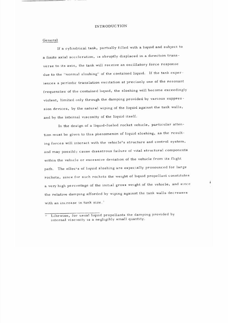
If a cylindrical tank, partially filled with a liquid and subject to
a finite axial acceleration, is abruptly displaced in a direction trans-
verse to its axis, the tank will receive an oscillatory force response
due to the normal sloshing of the contained liquid. If the tank exper-
iences a periodic translation excitation at precisely one of the resonant
frequencies of the contained hquid, the sloshing will become exceedingly
violent, limited only through the damping provided by various suppres-
sion devices, by the natural wiping of the liquid against the tank walls,
and by the internal viscosity of the liquid itself.
In the design of a liquid-fueled rocket vehicle, particular atten-
tion must be given to this phenomenon of liquid sloshing, as the result-
ing forces will interact with the vehicle's structure and control system,
and may possibly cause disastrous failure of vital structural components
within the vehicle or excessive deviation of the vehicle from its flight
path. The effects of hquid sloshing are especially pronounced for large
rockets, since for such rockets the weight of liquid propellant constitutes
a very high percentage of the in_t_al gross weight of the vehicle, and since
the relative damping afforded by wiping against the tank walls decreases
with an increase: in tank size_ _'
_,_:Likewise, for usual liquid propellants the damping provided by
internal viscosit_ Is a negligibly small quantity°
8/16/2019 Sloshing Nasa 2
http://slidepdf.com/reader/full/sloshing-nasa-2 8/81
Z
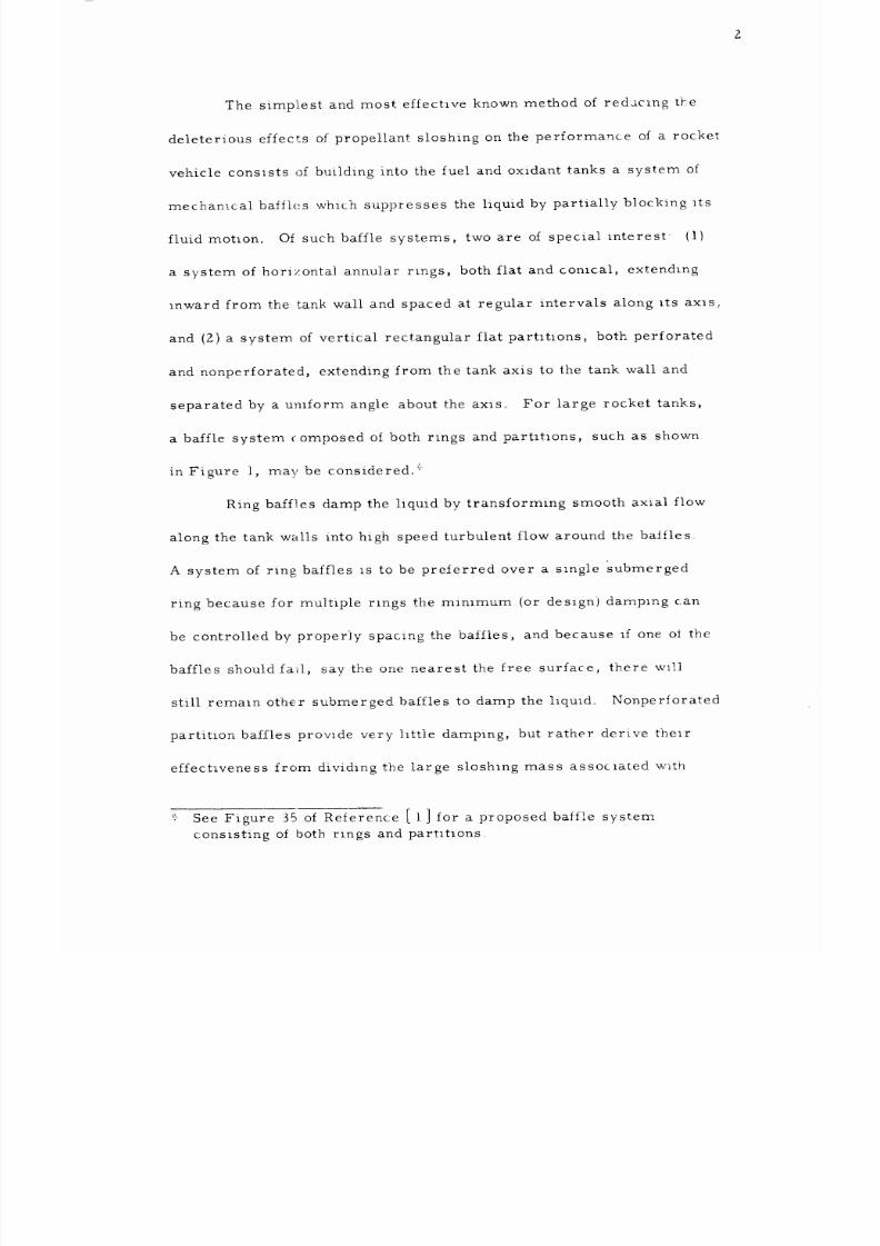
The simplest and most effectlve known method of redaclng the
deleterious effects of propellant sloshing on the performance of a rocket
vehicle consists of building into the fuel and oxidant tanks a system of
mecban_.cal baffles which suppresses the liquid by partially blocking its
fluid motlon. Of such baffle systems, two are of special interest {i)
a system of horizontal annular rings, both flat and conical, extending
inward from the tank wall and spaced at regular intervals along its axls;
and (Z) a system of vertical rectangular flat partltlons, both perforated
and nonperforated, extending from the tank axis to
the tank wall and
separated by a umform angle about the axiso For large rocket tanks,
a baffle system (_omposed oi both rlngs and parhtions, such as shown
in Figure I, may be consideredo _:_
Ring baffles damp the liquid by transforming smooth axial flow
along the tank walls into high. speed turbulent flow around the baliles_
A system of ring baffles is to be preferred over a single submerged
ring because for multiple rlngs the minimum (or design) damplng can
be controlled by properly spacing the baffles, and because if one ol the
baffles should fail, say the one nearest the free surface, there w11l
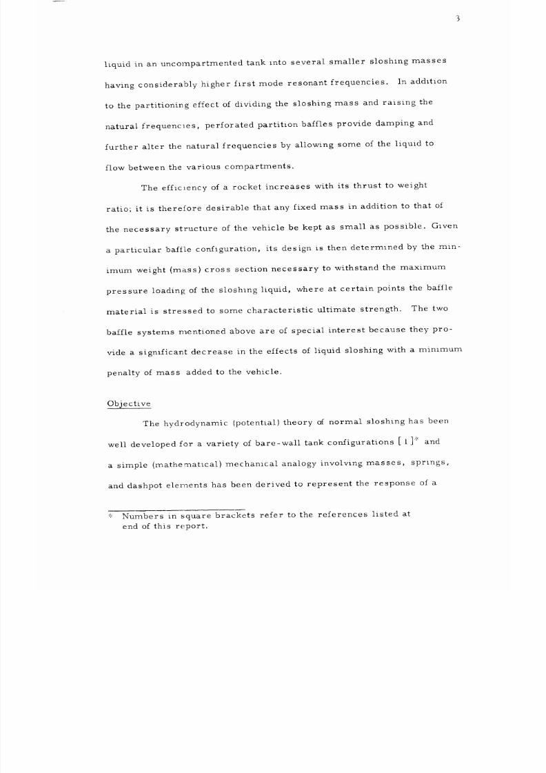
still remaln other submerged baffles to damp the liquld. Nonperforated
partition baffles provide very lltt]e damping, but rather derive thelr
effectiveness from dividing the large sloshing mass assoclated with
_'._-ee Figure 35 of Rel.erence [ I ] for a proposed baffle system
consisting of both rlngs and partltions
8/16/2019 Sloshing Nasa 2
http://slidepdf.com/reader/full/sloshing-nasa-2 9/81
8/16/2019 Sloshing Nasa 2
http://slidepdf.com/reader/full/sloshing-nasa-2 10/81
4
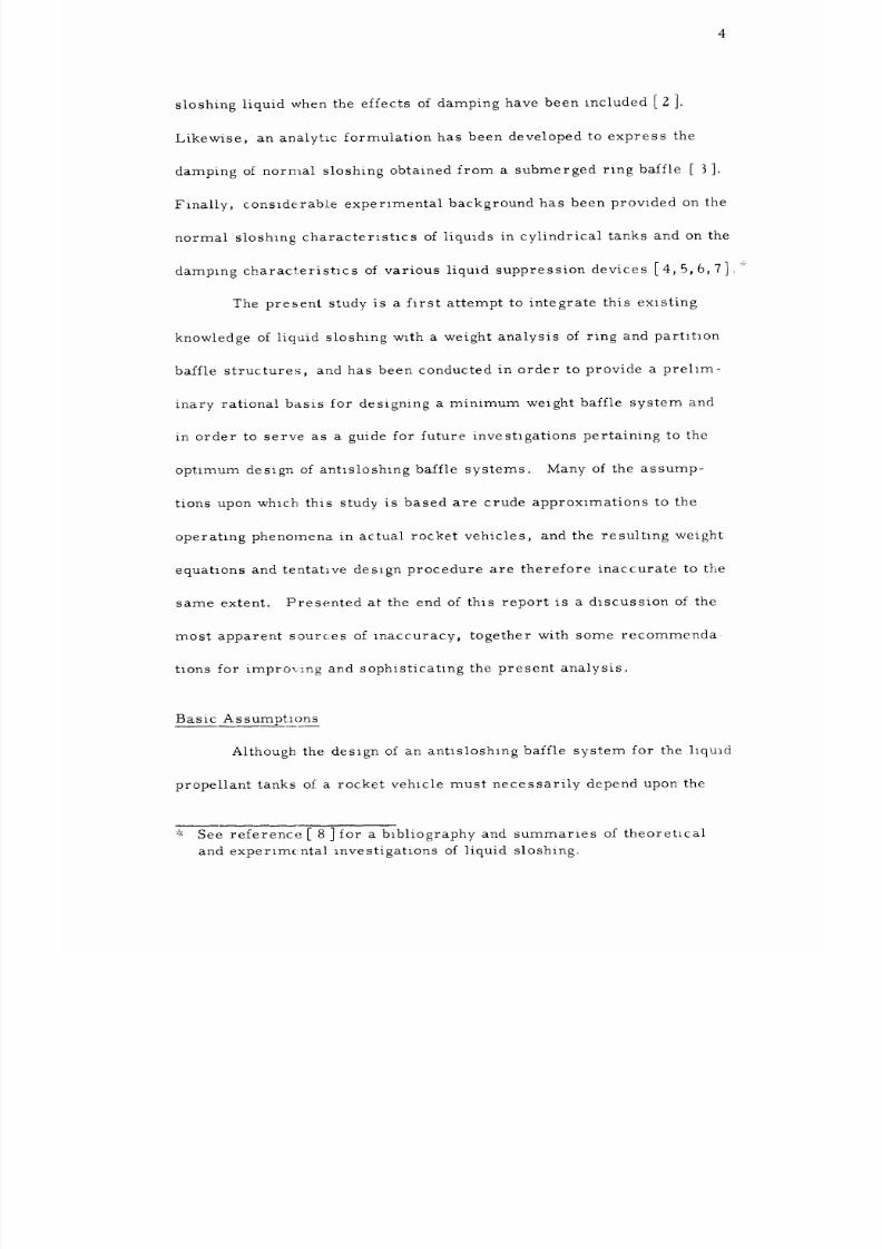
sloshing liquid when the effects of damping have been included [ 2 ]o
Likewise, an analytic formulation has been developed to express the
damping of normal sloshing obtained from a submerged ring baffle [ 3]0
Finally, conslderable experimental background has been provided on the
normal sloshlng characteristics of liquids in cylindrical tanks and on the
damping characteristics of various liquid suppression devices [4, 5, 6,7]o*
The present study is a first attempt to integrate this existing
knowledge of liquid sloshing with a weight analysis of ring and partitlon
baffle structures, and has been conducted in order to provide a prelim-
inary rational basis for designing a minimum weight baffle system and
in order to serve as a guide for future investigations pertaining to the
optimum design of antlsloshlng baffle systems. Many of the assump-
tions upon which this study is based are crude approximations to the
operating phenomena in actual rocket vehicles, and the resultlng weight
equations and tentative design procedure are therefore inaccurate to the
same extent. Presented at the end of this report is a discussion of the
most apparent sources of inaccuracy, together with some recommenda
tions for impro_.ng and sophisticating the present analysis.
Basic Assumptions
Although the design of an antisloshing baffle system for the llqu_d
propellant tanks of a rocket vehicle must necessarily depend upon the
_',_See reference [ 8 ]for a bibliography and summaries of theoretlcal
and experimental investigations of liquid sloshing.
8/16/2019 Sloshing Nasa 2
http://slidepdf.com/reader/full/sloshing-nasa-2 11/81
8/16/2019 Sloshing Nasa 2
http://slidepdf.com/reader/full/sloshing-nasa-2 12/81
semiempirically from a mathematical analogy consisting of mass-,
spring-, and dashpot-elements, referred to as an equivalent mechani-
cal model [2], the constants of whlch are adjusted to agree with avail-
able experimental data° The effects of damping on liquid sloshing are
adequately accounted for by the introduction of uniform linear dashpots
into the equivalent me'chanical model.
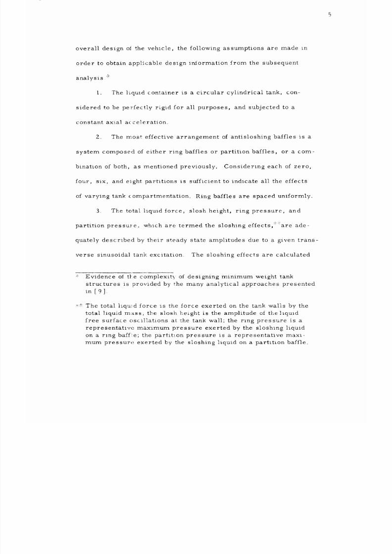
4. The tank excitation, being of random origin, is assumed to
have components of equal amplitude for each of the first mode liquid
resonant frequencies of the variously compartmented tanks. Further-
more, the sloshlng effects at each of these first resonances are always
the most severe, therefore the primary purpose of the proposed baffle
system is to suppress f_rst mode resonance sloshing effects, unless
there is an additlonal requlrement that liquid resonances belavOided
throughout some designated critical range of frequencies.
5. Liquid damping is the result exclusively of axial flow past
the ring baffles and of liquid exchange through perforations in the par-
tition baffles. Natural damping from wiping against the tank wall and
against the partitions, as well as that arising from the internal VlS-
cosity of the liquid are neglected° The minimum damping due to a
system of ring baffles is obtained from Miles' formula [ 3], in its
range of applicability, using the contribution of the first submerged
baffle to represent the damping for a multiple ring baffle system The
8/16/2019 Sloshing Nasa 2
http://slidepdf.com/reader/full/sloshing-nasa-2 13/81
7
damplng due to perforated partitions must be obtained from experlmental
data [4, 5] as there exists no analytic formula to express thls damping_
6. The minimum weight analysis is based upon the assumption
that the baffles behave as perfectly elastic thin plates, either solid or
composite, perforated or nonperforated_ of uniform thickness, which
derive their strength from resistance to bending. The baffles are as-
sumed to be sufficiently rigid that their deflections do not contribute to
the sloshing effects, and that a static stress analysis is valid for com-
puting the responses of the baffle structures to the hydrodynamic pres-
sure loadings. The pressure loadings and boundary condltions on the
baffles are assumed to be as shown in Figures 16 and 17.
8/16/2019 Sloshing Nasa 2
http://slidepdf.com/reader/full/sloshing-nasa-2 14/81
ANALYSIS OF LIQUID SLOSHING
Sloshing Analysis Approach
During the fhght of a typical rocket vehicle, various conditions
combine to produce transverse disturbances on the walls of its propel-
lant tanks° These disturbances may be conceived of as random in direc-
tion of application and in frequency distribution; however,
amplitude may usually be assigned to such disturbances°
these disturbances, the level of liquid in the propellant tanks, and there-
fore the principal resonant frequencies of the vehicle are constantly
changing with time. Presumably, for large tanks without liquid sup-
pression devices, normal sloshing of the liquid propellant will become
excessive at sonde point during the flight and the resulting forces applled
to the vehicle will cause disastrous Consequences to occur.
The two fundamental criteria for an antisloshing baffle system
are therefore_ (1) to prevent the total liquid force response from ex-
ceeding a certai1_ prescribed maximum value under all possible com-
binations of liquid level, tank orientation and acceleration, and external
tank excitation, and (2) to especially suppress the sloshing effects
throughout certalin designated frequency ranges in which the liquld
oscillations migLt reinforce the fundamental vibration modes of the
vehicle. Since knowledge of critical vibration frequencies depends
upon the specific design of each partlcular vehicle, and since thls
some maximum
In addition to
8/16/2019 Sloshing Nasa 2
http://slidepdf.com/reader/full/sloshing-nasa-2 15/81
report is intended to delineate a general design procedure, the Ioilow-
ing analysis is concerned primarily with the first of these criteria.
__SIoshinf[ Effects Derived from a Mechanical Model
In order to determine theoretically the effect of a sloshing liquid
on a vibrating tank system, a rigorous hydrodynamic analysis is reqmred
which takes into account the presence of the free liquid surface. Such an
analysis has been made for compartmented cylindrical tanks [1], as re-
quired for the present study; however, results from this analysis are
only partly available0 In the absence of such results, an equivalent
mechanical (mathematical) model for the sloshing liquid similar to that
presented in [2_, was developed and made to conform semi-empirical v
with available experimental data.
Figure 2 shows horizontal cross sections of compartmented tanks
having four, six_ and eight partJ.tions. The positions of the various com-
partments with respect to the direction of excitation are designated as
orientation 1 if ttae direction of excitation lies in the plane of one of the
partitions, and as orientation 2 is the direction of excitation hes in a
plane which bisects one of the compartments° _i VaIues of the nond_men-
• (coi)2
ional resonant _requency parameter, COi = a/g, are presented for
the lowest resonances associated with each of the compartments in the
particular orientations shown, as obtained experimentally from [4].
: ,': This distinction exists only for an even number of compartments.
8/16/2019 Sloshing Nasa 2
http://slidepdf.com/reader/full/sloshing-nasa-2 16/81
I0
F_gure 3 shows the higher harmonic frequencies correspondlng to these
first resonances and was obtained by passing smooth curves through a
plot of the natura] resonant frequencies presented in [5].
Figures 4_ 5_ and 6 present, respectively, the total force re-
sponse, the slosh height responses and the maximum partitlon (or wall)
pressure response_ ior a sloshing liquid in an uncompartmented tank.
These iigures show_ respectively, the correlatlon c__ the theoretlcal
results obtalned from the equivalent mechanical model for various
damping_ with the total force response data obtained from [4], unpub-
lished slosh height data, and wall pressure data obtained from [6].
Shown also in F_gure 6 (and likewise in Figures 7,8, 9) is the total force
response of the liquid mass that would be obtained if the hquid were
frozen solid.
Figures 7, 8, and 9 present the total undamped force responses
for cylindrlcal tanks compartmented with four, six, and eight partitlons,
respectively, and exclted in the directlons designated in Figure 2 as
orientation i0 The experimental data shown in Figure 7 for the four
partition tank _s that obtalned from [4] for a half tank, and the experi-
mental data shown in Figure 9 for the eight-partition tank was obtained
from [ 5]. The resonant frequencies for the six-partition tank were
obtained by interpolating between those for the four- and eight-partitlon
tanks, since there _s no experimental data available for the _orce response
in a six-partition tank, as shown in Figure 8
8/16/2019 Sloshing Nasa 2
http://slidepdf.com/reader/full/sloshing-nasa-2 17/81
iI
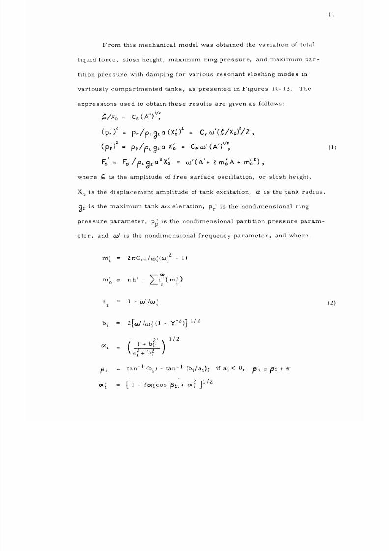
From th_s mechanical model was obtained the variation of tota]
liquid force, slosh height_ maximum ring pressure, and maximum par-
tition pressure with damping for various resonant sloshing modes In
variously compartmented tanks, as presented in Figures I0-13. The
expressions used to obtain these resu]ts are given as follows:
_/Xo = C_(A") '/',
(p')' = p,./io,_l,,:,(x;,)'- : c_o.,'(_/Xo)'/z,
,,)Z *
(P" = P,/e" g,° Xo -- c, _' (A')'';
' /io ' , ,,
= % . _,,:,_Xo = _' (A'+ z _o A + _o ),
where _ is the amphtude of free surface oscillation, or slosh height,
X o is the displacement amplitude of tank excitation, a is the tank radl.us,
_z is the maximum tank acceleration, Pr' is the nondimensional ring
pressure parameter_ pp is the nondi.mensional partitlon pressure param-
eter, and co' 1.sthe nondimenstonal frequency parameter, and where:
Z
z7
r_h i'(m')
'
o 1
a, = 1 uY/co
1 1
z)
bi = z[_'/w; il ..
Z' )
x i = 1 + bi_
\
y-z)] t/z
1/2
tan_l (b ij _ tan-1 (b i al);
if at< O,
119_.
= /9:
+,r
8/16/2019 Sloshing Nasa 2
http://slidepdf.com/reader/full/sloshing-nasa-2 18/81
o<_ sinai )
' tan -1 1 -o, cos_i ' if a. < 0 _'i _'i +'_
i = - I ' I ' =
A i =
o_im l,
A l=o_'i/a)i
A
A _
A TI
_I Ai cos /Bi
i J I A A II cos ( -_j
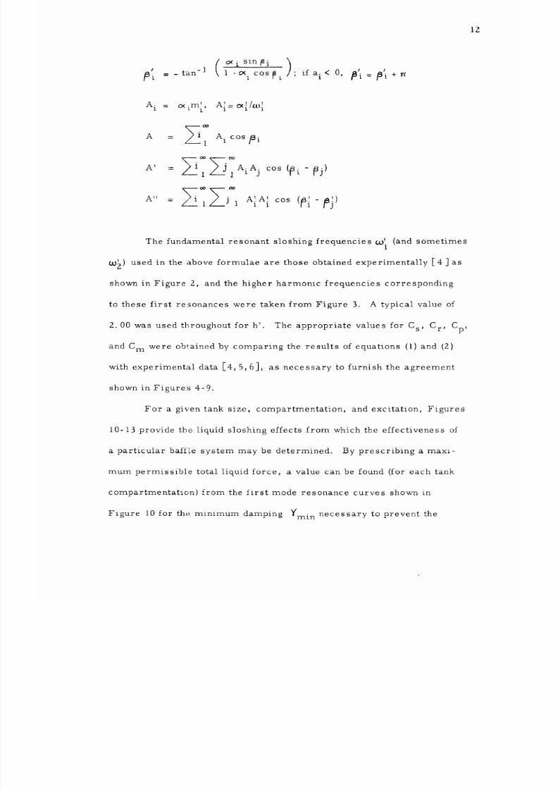
12
' (and sometimes
The fundamental resonant sloshing frequencies oJ 1
OJ_) used in the above formulae are those obtained experimentally [4 ]as
shown in Figure 2, and the higher harmonic frequencies corresponding
to these first resonances were taken from Figure 3. A typical value of
2. 00 was used throughout for h _. The appropriate values for C s, C r, Cp,
and C m were obtained by comparing the results of equations (I) and (2)
with experimental data [4, 5, 6], as necessary to furnish the agreement
shown in Figures 4-9.
For a given tank size, compartmentation, and excitation, Figures
10-13 provide the liquid sloshing effects from which the effectiveness of
a particular baffle system may be determined. By prescribing a maxi-
mum permissible total liquid force, a value can be found (for each tank
compartmentatton) from the first mode resonance curves shown in
Figure I0 for the minimum damping Ymin necessary to prevent the
8/16/2019 Sloshing Nasa 2
http://slidepdf.com/reader/full/sloshing-nasa-2 19/81
II
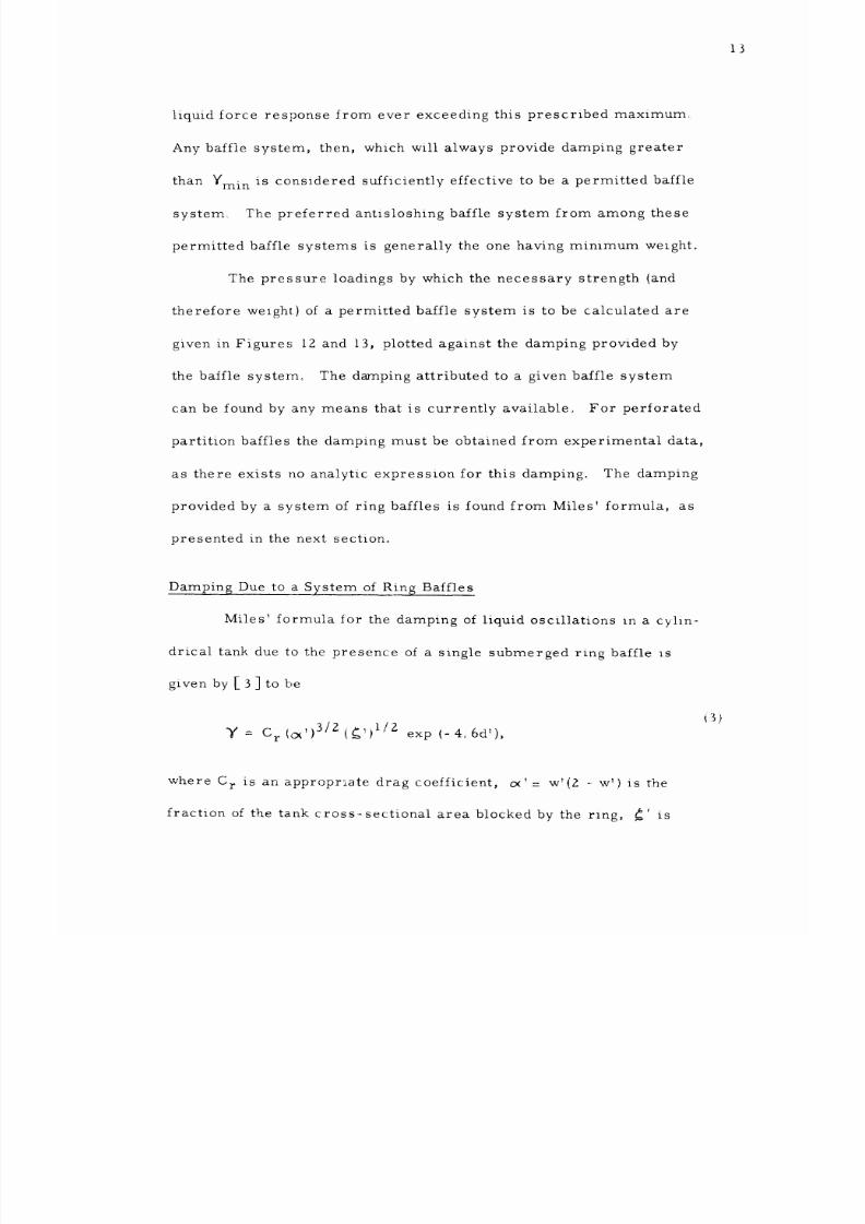
liquid force response from ever exceeding this prescribed maximum
Any baffle system, then, which will always provide damping greater
than Ymin is considered sufficiently effective to be a permitted baffle
system_ The preferred antisloshing baffle system from among these
permitted baffle systems is generally the one having minimum welght.
The pressure loadings by which the necessary strength (and
therefore we_gh_)of a permitted baffle system is to be calculated are
given in Figures 12 and 13, plotted against the damping provided by
the baffle system° The damping attributed to a given baffle system
can be found by any means that is currently available° For perforated
partition baffles the damping must be obtained from experimental data,
as there exists no analytic expression for this damping_ The damping
provided by a system of ring baffles is found from Miles' formula, as
presented in the next section.
Damping Due to a System of Ring Baffles
Miles '_formula for the damping of liquid oscillations In a cyl_n-
drical tank due to the presence of a single submerged ring baffle is
given by [ 3 ] to be
Y = Cr(o_')3/2(_'_) I/Z exp (-4o6d'),
where C r is an appropriate drag coefficient, o_' = w _(2 - w') is the
fraction of the tank cross_sectional area blocked by the ring, _' is
8/16/2019 Sloshing Nasa 2
http://slidepdf.com/reader/full/sloshing-nasa-2 20/81
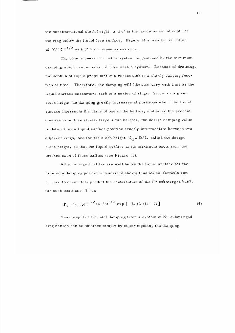
14
the nondimensional slosh height, and d_is the nondimens_onal depth of
the ring below the liquid free surface. Figure 14 shows the var_stlon
of y/( _)I/Z with d' for various values of w_o
The effectiveness oI a baffle system is governed by the mlnimum
damping which can be obtained from such a system° Because of draining,
the depth h of liquid propellant in a rocket tank is a slowly varying func-
tion of time. Therelore, the damping will likewise vary with time as the
liquid surface encounters each of a series of rings. Since for a given
slosh height the damping greatly increases at positions where the liquid
surface intersects the plane of one of the baffles, and since the present
concern is with relatively large slosh heights, the design damping value
Is defined for a liquid surface position exactly intermediate between two
adjacent rings, and for the slosh height _d = D/Z, called the design
slosh height, so that the liquid surface at its maximum excurs_.on just
touches each of these baffles (see Figure 15).
All submerged baffles are well below the liquld surface for the
minimum damping pos:t_ions described above; thus Miles _formula can
be used to accurately predict the contribution of the i th submerged baff]e
for' such positions [ 7 ] as
$/z _D,/Z)I/2
T i = Cr t_')
exp [- 2 3D:(21 - 1)].
Assuming that the total damping from a system of N" submerged
ring baffles can be obtained s_mply by superimposing the damping
(41
8/16/2019 Sloshing Nasa 2
http://slidepdf.com/reader/full/sloshing-nasa-2 21/81
]5
contributions of t_e individual baffles, the design damping for such a
system can be written as
Td/(_,)3/z = Z(D,)I/2 _-_ N
exp _-Zo 3D'_(2i - 1)],
where N" is the integer which lies between h'/D'-I and h'/D _. Figure
presents the _ar_at_on of Yd/(O¢') 3/2 with D'; this figure shows
5
also the damping contribution of the first submerged baffle versus D_o
The latter has been shown generally to be the better assumption for
expressing the damping due to a system of multiple ring baffles [ 7]_
Here, as before, a typical value of Z0 00 was used for h _, and 2. 83 was
used for C r.
(5)
8/16/2019 Sloshing Nasa 2
http://slidepdf.com/reader/full/sloshing-nasa-2 22/81
16
ANALYSIS OF BAFFLE STRUCTURES
Bending Moments in Rings and Partitions
Throughout this analysis the baffles are assumed to be thin plates
which derive thelr strength from resistance to bending. In particular, a
composite sandwich plate will be considered which has a significantly
lower specific weight {weight per unit area) ]'c than that of an ordinary
solid plate for an equivalent bending stiffness. In order to establish
limitlng bounds on strength-weight characteristics, the baffles would
have to be considered as large deflection membranes, which derive
thelr strength from resistance to extension and shear deformations and
exhibit negligible bending stiffness, and considered also from a plastic
analysis approach whereby a general collapse load can be predicted
Inclusion of these latter effects into the strength analysis was considered
beyond the scope of the present investigation°
A basic assumptlon of this preliminary study is that the walls of
the cylindrical tank are perfectly rigid, or equivalently, that deflectlons
of the internal balfles are independent of deflections of the tank,
verselyo Thls assumptlon provides two s_mplifications_ First, slnce a
given baffle does not contribute to the strength of the tank, the tank may
be disregarded _,_ computing and comparing the weights of various baffle
systems° Second, since deflections of the tank and baffle are completely
uncoupled, any convenient boundary conditions may be chosen for the
and c on-
8/16/2019 Sloshing Nasa 2
http://slidepdf.com/reader/full/sloshing-nasa-2 23/81
17
balfles at the tank wall. The most realistic edge conditions for plates
used as ring and partition baffle structures are as follows. The ring
baffles are assumed clamped around their outer edges {welded to the
tank wall_ and e:ther (1) free, or (Z) simply supported {by stringers)
around their inner edges° The partition baffles are assumed clamped
along the edges in contact with the cylinder wall and coincidlng with
the cylinder axis, and simply supported along the other two edges.
The functions representing the transverse pressure distribu-
tions applied to the baffle structures (see Figures 16 and 17) were
chosen so as to approximate as closely as possible those encountered
in practice and yet provide analytical solutions to the thin plate prob-
lems. For a ring baffle, the maximum pressure distribution will
vary in a way that is nearly sinusoidal around the ring circumference
[3]° However, since the strength analysis is based only on the maxi-
mum bending moment incurred, and since this maximum bending mo-
ment is dependei1t largely upon the local {maximum) pressures, it was
assumed that a uniform pressure distribution over the entire ring sur_
face would be accurate enough for the present purposes. _#_ The wall
pressure distrib_Ltions observed [ 6 ] for the first mode resonances in
an uncompartmented tank vary from nearly zero at the tank bottom to
_=_ This assumption is especially good for rings with small annular
width w'.
8/16/2019 Sloshing Nasa 2
http://slidepdf.com/reader/full/sloshing-nasa-2 24/81
18
a maximum value near the liquid free surface_, Due to the obvious
similarity, the pressure distributions on the partition baffles were
therefore assumed to vary hydrostatically°
R1.ngbafl]e. Using the basic equations for the symmetrlca]
bending of a circular plate having a centrally located hole, as given
in section 17, pages 63-68 of [i0], together with the simplified edge
conditions prescribed above and the uniform transverse pressure dis-
tribution Ppir, @I= Pp, as shown in Figure 16, the following expres-
sions are obtained for the nondimensional (maximum) bending too-
ment parameter :nr_.
(l Free around r = b
(2
(s+y)b 'z- (I-y)
cx = (v_y)b,_2+(J+_) , _ =
simply supported around r : b:
8' +2<z-,)b] ,
+
(I-'.-')Inb'
(f- y) b'-_+ (,+ _)
l ]
--j - o_ + , 'z ,_@-z/_ ,
m_
>_=
,
(I - b'a) z
,
I - b'_+ zb'LIn b'
cx = I_ b,2+ 2.1nb, _ /3 = I_ b,a+Zlnb ,
Partition bafl]e,, By a method similar to that used to obtain
equation (_), pag,-_ Zl0 of [I0], the following expression is obtained
for the bending moment distribution along tee edges r = 0, a, of a plate
subject to a hydrostatic transverse pressure loading Pp{r,z) = ppz/b,
as shown in Figare 17, and given the edge conditions prescribed above
(6)
(7
8/16/2019 Sloshing Nasa 2
http://slidepdf.com/reader/full/sloshing-nasa-2 25/81
19
and m '
P
=
e0s n T).
P
The nondimensiona]
maximum)
bending moment parameter mp _ is
therefore glven by
t) 2 2
= [M i(o,a),7t]mo /p,o i9:
Figures _6 and 17 show plots, respectively, of m r' versus w',
versus _' for h/I[-_ i.
Plate Perforation Relationships
In seeking to determine more eff ective, light weight baffle
structures, it is natural to consider perforation of the baffle plate
material as a means of reduclng overall baffle weight° Likewise,
preliminary tests [ 5] on small models show that certain perforation
improves the da:nplng effectiveness of partition baffles_ :_ Therefore_
the effects of perforation on the strength-_weight characteristics of a
baffle structure will be considered as follows,. Stress concentratl.ons_
due to the small radius holes are neglected,_ For holes of diameter
dp centered on a square ]attlce of spacing Dp_ as shown _n Figure 18,
the following relationships apply
.,i,The damping provided by nonperforated ring baffles is always greater
than that provided by equtvalent perforated ring baffles°
8/16/2019 Sloshing Nasa 2
http://slidepdf.com/reader/full/sloshing-nasa-2 26/81
2O
e o = (.r-r/4)(clt_/f_); ,
#
k 0 = I -- E 0
ko = _ . i/zz (e o/'r'r)
k d I - _o
k° = (ko') ''_- : [i- z(eo/_-)'"'Ll''" '
where ko_ is the perforation fraction, ko" is the minimum load bearing
area fraction, and k o is the plate perforation factor which appears in
all the subsequent weight, equations° G o is the percentage area remo_edo
For boles of diameter dp centered on an ec_uilateral-trian_ula,r
lattice of spacing Dp, the following relationships apply:
e, = (._/z.i2,1(cll,/D_) z ,
k"
i = I- EI_
#1
k, = I - (z_,/_)'i_,
k,' I - c-i
k, =
(k, )_ _ =
[I-(zJ_e,/"r)'"] ''_
'
The variation of k m with Era, where m is either 0 or l depend-
ing on the conventions established above, is shown in Figure 18; it is
seen from this figure tKat the k m are greater than 1 for all moderate
values of Em_ Therefore., contrary to widespread belief, there is no
distinct weight saving to be gained by perforation, except for the case
of very thin plates w£1ere the thirckness is restricted by manufacturing
tolerances rather than by optimum strength design° It may, neverthe-
less, be advantageous 1o use perforated partition baffles because of
the hydrodynamic: damping prowded by plate perforation,
1 0 )
1 1)
8/16/2019 Sloshing Nasa 2
http://slidepdf.com/reader/full/sloshing-nasa-2 27/81
Z1
Including the effects of elastic stress concentrations would
further degrade the strength-weight characteristics of perforated
plate so
Minimum Specific Weights Based on Optimum Bending Strength
Expressions for the maximum bending moments encountered
in ring and partition baffle structures due to the hydrodynamic pres-
sure loading of a sloshing liquid have been presented previously. These
bending moments are resisted by stresses induced in the baffle material,
depending upon the particular plate cross section used for the baffle. By
assigning a characteristic ultimate tensile strength S which the plate
material can withstand before failing, and by designing the plate cross
section such that the maximum induced tensile stresses are just equal
to S, an optimum weight design will be established for the particular
assumed plate cross section.
Solid plate. For a solid plate, the maximum stresses in terms
of the bending moments are given by equations (44) of [I0]. The maxi-
mum tensile stress condition due to bending, therefore becomes
/ "t (p ")( It/-ma x = S = G mk km
s
_ k/k.-, m_ )z
so that the optimum thickness is given by
• /
ts = mk(Gpk/ % S)
and the minimum specific weight (weight per unit area) of the solid
lz)
(1 _)
8/16/2019 Sloshing Nasa 2
http://slidepdf.com/reader/full/sloshing-nasa-2 28/81
22
plate can be wrltten as
J /_ • i p
f \
where K s = _= 2.45 is the cross section factor for a solid plate,
Simple composite sandwich plate. The weight of a baffle
sys-
tem can be significantly reduced by using a plate cross section with
a greater moment of inertia (bending stiffness) per unit cross sec-
tional area than that of a solid plate. Examples of such advantageous
cross sections are the accordion, corrugated, and sandwich type con-
structions. To demonstrate the weight saving that can be gained in
this manner, the strength-weight characteristics of a simple sandwich
plate will be developed as follows. ':_
Consider a simple composite sandwich plate, consisting of two
outer sheets of thickness to separated a distance T c by a vertical grid-
work of
square
cells of sides d c and thickness _Ktc, as shown in Figure
19. The critical strength criteria for determining the dimensions of
(14)
:_¢
Sandwich type construction has found only limited use in missile
shell designs primarily because of the inadequacy of welding tech-
niques to make full use of the material strength and because the
thermal stresses induced in the tank walls by cryogenic fuels tend
to separate the outer sheets of a sandwich plate (see pages 3-4 of
[9]). The use of sandwich type construction for baffles in large
rocket tanks Is attractive, however, since internal baffles are not
exposed to thermal stresses, and since the recent development of
high strength, low distortion aluminum welds [II] makes possible
the fabrication of high quality sandwich plates.
8/16/2019 Sloshing Nasa 2
http://slidepdf.com/reader/full/sloshing-nasa-2 29/81
23
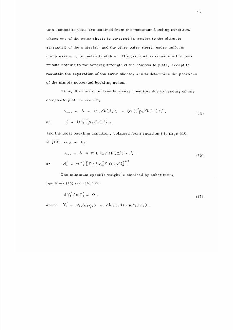
this composite plate are obtained from the maximum bending conditlon,
where one of the outer sheets is stressed in tension to the ultimate
strength S of the material, and the other outer sheet, under uniform
compression S, is neutrally stable. The gridwork is considered to con-
tribute nothing to the bending strength cf the composite plate, except to
maintain the separation of the outer sheets, and to determine the positions
of the simply supported buckling nodes.
Thus, the maximum tensile stress condition due to bending of this
composite plate is given by
,s / 2- //// r /
_,,o. = S = rnk/k_L_r_ = (mk)pk/K_t_tr_ .
2.
--' ( ') p ,
r Lc = mk k/l<:" [c
and the local buckling condition, obtained from equation (j), page 310,
of [i0], is given by
G_o,
= S _ _ZEt_/gk:d_(,-_') ,
_, IZ
or d" -- [E/Sk'o',S .
The mimmum specific welght is obtained by substituting
equations (15) and 16) into
dY//dt_ = 0 ,
where Yc
=
Y: , ,a = zk,:tc(,+KT,/dc).
(15)
(16
(17
8/16/2019 Sloshing Nasa 2
http://slidepdf.com/reader/full/sloshing-nasa-2 30/81
Z4
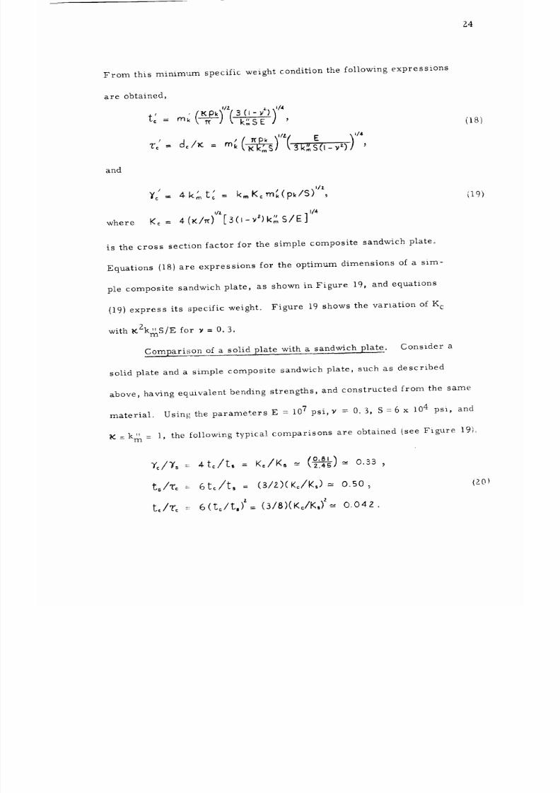
From this minimum specific
weight
condition the following expressions
are obtained,
f
£
'
3
(J-_*)
= mk k_g E '
and
, t x k "tz( E ),,,4
.
/
¥c 4k' ' K m_('pklS)z_-
tG ----" kvn C
Vz
114
where
Kc = 4(_/_) [S(I-_Z) kgS/E]
is the cross section factor for the simple composite sandwich plate°
Equations 18) are expressions for the optimum dimensions of a sim-
ple composite sandwich plate, as shown in Figure 19, and equations
19) express its specific weight° Figure 19 shows the variation of l{c
_2kmS/E for _ : 0. 3.
ith
Comparison of a solid plate with a sandwich plate. Consider a
solid plate and a simple composite sandwich plate, such as described
above, having eqaivalent bending strengths, and constructed from the same
material° Using the parameters E = 107 psi, y -- 0o 13,S =6 x 10⁴ psi, and
m --
,..
(o.81) ,..,
c/75 =
4to/t,
=
K_/K,_
_,2-:_# 0.33
ts/rc :-6to/t, = (s/z)(K,./K_)-= o.50,
t_/T_ 6 (t_/t,) z (3/8)(KJK,) z
-: = -- O.04Z .
(_8)
(19_
i, the following typical comparisons are obtained (see Figure 19).
{g0)
8/16/2019 Sloshing Nasa 2
http://slidepdf.com/reader/full/sloshing-nasa-2 31/81
25
It can be seen from the first of equations (20) that the theoretica]
specific weight of a simple sandwich plate is approximately one-third that
for a solid plate of the same (typical) material° Of course, the use of
sandwich plates is lestricted to those applications where the thickness of
the outer sheet material is large enough to be satisfactorily fabricated°
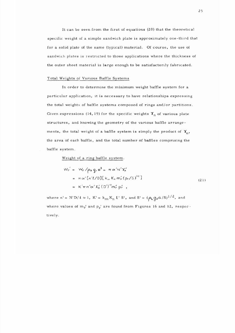
Total Weights of Various Baffle Systems
In order to determine the minimum weight baffle system for a
particular application, it is necessary to have relationships expressing
the total weights of baffle systems composed of rings and/or partitions°
Given expressions (14, 19) for the specific weights _'n of various plate
structures, and knowing the geometry of the various baffle arrange-
ments, the total weight of a baffle system is simply the product of _'n'
the area of each baffle, and the total number of baffles comprising the
baffle system°
Weight of a ring baffle system°
/
Wr
= K
'l'r
n'_' Xo ( D')-'m; p; ,
where n'= N'D/I[ _ l, K'= kmK n [' S', and S': (pug2Ct/S) 1/2, and
where values of m r ' and Pr are found from Figures 16 and 12, respec-
tivelyo
(2 i)
8/16/2019 Sloshing Nasa 2
http://slidepdf.com/reader/full/sloshing-nasa-2 32/81
26
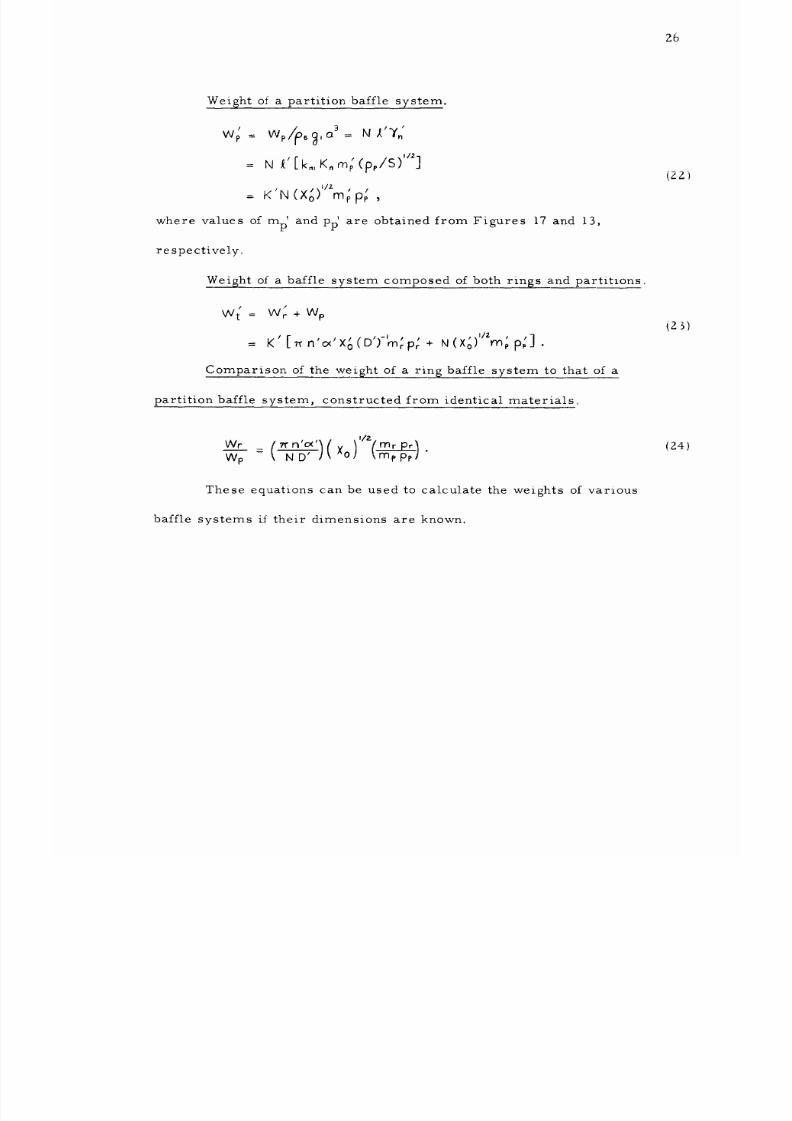
Weight of a partition baffle system.
wp = Wp ._,a 3= NX'Y£
=
N _' [ k., K, m; (p,/S)"_]
j _
\1/7.. I
= K N(AoJ mpp_ ,
where values of rap' and pp' are obtained from Figures 17 and 13,
respectively°
Weight of a baffle system composed of both rings and partitlons.
I /
W t
=
W r
+
Wp
t t p p ,I/2
,
= K
[_n o Xo D )- mrpr
+ N(Xo) mpp;].
Comparison of the wei__ht of a rin_ baffle system to that of a
partition baffle system, constructed from identical materials°
(22 ')
(25)
w,- __
n :'< l
( xo _''(_r P_/
Wp - ( N D' / ,' \mr, pp/ "
(24)
These equations can be used to calculate the weights of various
baffle systems i_ their dimensions are known.
8/16/2019 Sloshing Nasa 2
http://slidepdf.com/reader/full/sloshing-nasa-2 33/81
27
DESIGN OF A BAFFLE SYSTEM
Equations 21-Z4, together with the curves shown in Figures
10-19, are sufficient to determine the mlnimum weight baffle system
for a given rocket vehicle application within the limitations imposed
by the basic assumptions. The analysis may be simplified, however,
by determining algebraic approximations to these curves, and by sub-
stituting these approximations into the appropriate weight equations.
The following analysis determines the minimum weight of baffle sys-
tems composed of rings and/or 0,4,6, or 8 partitions.
Approximate Relationships
Liquid sloshing relationships. Considering only the first
resonant sloshing modes for each of the curves shown in Figures
10-13, since they are usually the most severe, the following approx-
imations are valid for sma]l damping (Y,_ 0. 0Z),
Fo'
=
C,./_. "¥(N)= c,./5'.
.4(N)/Xo --. Cz,.,/¥.
p,.(N) "- C _N/¥
#
.4'(N) --' (c2./c,.) Xo_,_
(c3,.,/C,.) %',
l .i//. -i/l] -
/'i/Z
pc(N)= C4.//(7J -_ [C4.1(C,.) j(r0),
where the coefficients CMN are given by the following table, and where
CrN, CpN, and CTIXT are fac.tors, involving products of the CMN, whlch
arise in the derivation of the weight equations to be presented later.
(ZS)
8/16/2019 Sloshing Nasa 2
http://slidepdf.com/reader/full/sloshing-nasa-2 34/81
28
N
0
4
6
8
CIN
1.33
0.60
0.43
0o17
C2N
0.81
0°60
0.52
0o 46
C3N
1.31
1.15
1,05
O. 99
C4N
0.81
O, 54
0.46
0.29
CrN
2.01
O.97
0.70
0.28
CpN
0
2.79
4.22
5°53
CTN
0
1.96
2.32
2. 04
TABLE I. Coefficients of the Approximate First Mode Sloshing
Relationships
Ring baffle damping relationships. Unfortunately, the curve
(obtained by superposition} for the design damping of a system of multi-
ple ring baffles shown in Figure 15 approaches infinity as the ring spac-
ing D' is decreased to zero, whereas in actuality the damping should
always remain finite and should, in fact, be zero for D' = 0. A prelim,-
inary experimental investigation [7 ] of multiple ring baffle arrangements
has shown that the damping for such baffle systems is approximately that
given by Miles' equation considering only the contribution of the first
submerged baffle Using this assumption, where _ = D_/Z, the following
relationships are obtained.
Y
=
C,- (cx')_/z(_')'/2exp ( -z.3 D') , cx"<< 1
or
D' '1_7 ' '
J_ o_ _.5, p .= e (C,NXo)'"'_o'/C,N.
,26_
8/16/2019 Sloshing Nasa 2
http://slidepdf.com/reader/full/sloshing-nasa-2 35/81
29
Total damping relationships° For a general baffle system
composed of both rings and partitions, the total damping is given by
Y' .-. %" + Cr (_'Yz(,,4')'/_exp (-z.3 D') ,
D' p, (+)[ ,.x0 1''
' - (I-
./,,)zj
where %t_ is a]] liquid damping other than that provided by ring baffles,
where the various contribut_ons to the damping are assumed to be
additive, and where ¥"= Y_/Y.
Maximum bending moment relationships. The curves shown
in Figures 16 and 17, for the maximum bending moment parameters
of ring and partition baffle structures, are closely approximated by
the following expresslons
/ #
mr N 0.34" _W ,
t
rnp _-- 0.2-63 - 0.09/1',
where _ = I for ling baffles simply supported around their inside
edges and _o = 2 for ring baffles whose inside edges are free, and
where the baffle width can be approximated by
W ' O_") '/z
O_
<< 1..
I
-
(i- "-' (cx'/2)(l+_Y4) "" _'2 _
.
(27
(28 ,'
29
Minimum Weight E_.quations
We}__ht o± a par'titlon baffle system. Combining equations (22 ,
(25d), and 28b), the fol]ow_.ng expression is obtained for the total
weight of a system of partit_or,_ baffles°
8/16/2019 Sloshing Nasa 2
http://slidepdf.com/reader/full/sloshing-nasa-2 36/81
3O
P K / t I/2 n s
Wp
=
N(×o) mppp
_. -- • I F I .llZ
K'Cp. (0. Z83 0 09/_.')(Xo o) ,
N)I/2
where CpN = NC4N/(C I can be obtained from Table i.
For a baffle system composed of perforated partition baffles
alone, which provide a maximum damping _p, the following formulas
apply,
FO'(p _--C,N //Yp ,
/ j . llz
Wp(p) ""
0.283
IK'KIC4N
(I
-
0,317/_,')(
Xo/YP) .
Minimum wei6ht of a tin 6 baffle system° Combining equations
(21), (25c), 26b), (28a), and (29), the following expression is obtained
for the total weight of a system of ring baffles,
Wr = K'I_ _"-' ' '
n_ Xo(U ; turF) r
=
K'_
'
' '
')(o.,__' )
n o( Xo (J. 5/In _#p _ )(FoC3N/CIN
p r p2
: 0.80 K'_ n'(C3N/C,N) XoF o (o_)/Inoc_'.
The value of o¢_for which W r' is a minimum is obtalned by
equating the first derivat_.ve to zero, as
dWr/dcx'= 0
=
from which
0.80K'__'(C,,/C,N)_FO'_Vl__'_')CZ'/_=_'),
(3
0
)
(31
D' : In o_'/I.5 : 0.33,
, ,,,/j_'
x = e : o,83 c,./r o'(c_.xo) '/'
'
'c (xo)'_
'
W r "" I.II K
_on rN FO ,
t32)
8/16/2019 Sloshing Nasa 2
http://slidepdf.com/reader/full/sloshing-nasa-2 37/81
:31
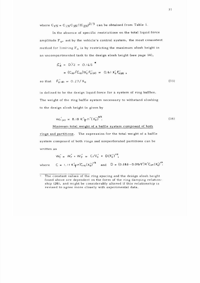
where CrN = CINC3N/(C2N )2/3 can be obtained from Table l0
In the absence of specific restrictions on the total liquid force
amplitude Fo, set by the vehicle's control system, the most consistent
method for limiting F o is by restricting the maximum slosh height in
an uncompartmented tank to the design slosh height (see page 14),
J P
(Czo/C,o)XoFo_d) = 0.6iXoFocd_,
/
so that Fo_a) _- O.Z7/X o
is defined to be the design liquid force for a system of ring baffles.
The weight of the ring baffle system necessary to withstand sloshing
to the design slosh height is given by
Wrcd]
=
8.18 K'_n'(X0 .
Minimum total weight of a baffle system composed of both
rings and partitions. The expression for the total weight of a baffle
system composed of both rings and nonperforated partitions can be
written as
c/to
( = w,: + wp =
where
C = I.
I,
K'_ n'CrN (Xo) '/3
/. I/2
+ D(F o) ,
and D = (o.za3 - o.o9/_')K'Cp. (x£) '/_.
The constant values of the ring spacing and the design slosh height
found above are dependent on the form of the ring damping relation-
ship (Z6), and might be considerably altered if this relationship is
revised to agree more closely with experimental data.
(33)
(:34)
8/16/2019 Sloshing Nasa 2
http://slidepdf.com/reader/full/sloshing-nasa-2 38/81
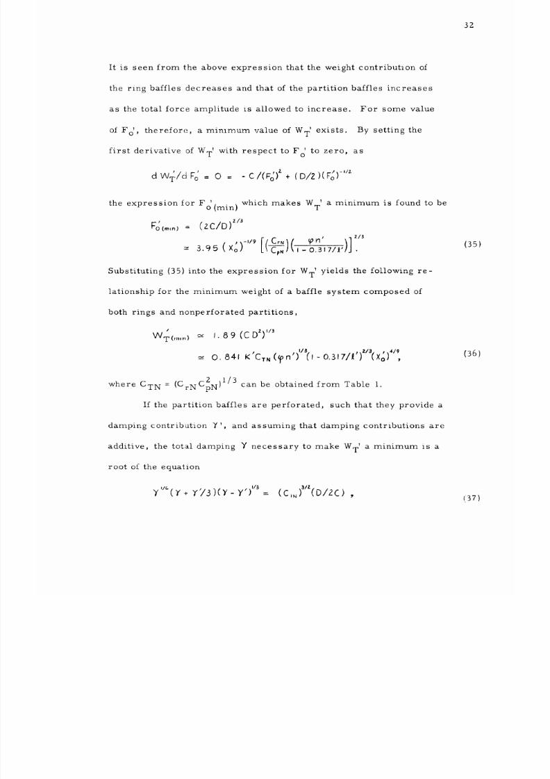
:32
It is seen from the above expression that the weight contribution of
the ring baffles decreases and that of the partition baffles increases
as the total force amplitude :s allowed to increase° For some value
of Fo' , therefore, a mimmum value of W T' exists. By setting the
first derivative of W T' with respect to F ' to zero, as
O
w,_/a%'= o = - c/(_-_#+(D/Z
)(
1
the expression for F ° (min)
_"0 (ml n ) =
Substituting (35) into the expression for WT' yields the following re-
lationship for the minimum weight of a baffle system composed of
both rings and nonperforated partitions,
/
WT(m,.) = I. 8 9 (C
DZ)'/3
p P )1/3 .Z/3. t _,1-/9
-_ O.841 K C-r,(_pn ('1-O.3W7/_) (%; ,
IC C 2 _1/3
where CTN = _ rN pN p can be obtained from Table I.
If the partition baffles are perforated, such that they provide a
damping contribL:tion YI, and assuming that damping contributions are
additive, the total damping Y necessary to make WTI a minimum is a
root of the equation
Y /_ Y
+
Y'/3)(Y-Y')
'/_ (C,, O/2C)
which makes W T' a minimum is found to be
(2C/D) _/_
)]'
.9s (Xo L_c,.,(,-o._,,/_' •
(35)
(36)
(37)
8/16/2019 Sloshing Nasa 2
http://slidepdf.com/reader/full/sloshing-nasa-2 39/81
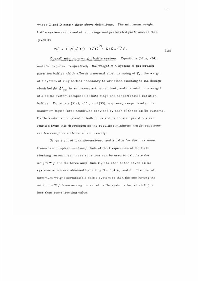
where C and D retain their above definitions° The minimum weight
baffle system composed of both rings and perforated partitions is then
given by
/ 4/3 . t/z..
W r = (C/C,.)Y(I-Y'/Y) + D(C,_) /Y.
Overall minimum weight baffle system° Equations (:lib), (34),
and (36) express, respectively: the weight of a system of perforated
partition baffles which affords a normal slosh damping of Yp ; the weight
of a system of ring baffles necessary to withstand sloshing to the design
slosh height _'(d> in an uncompartmented tank; and the minimum weight
of a baffle system composed of both rings and nonperforated partition
baffles. Equations (31a), (33), and (35), express, respectlvely, the
maximum liquid force amplitude provided by each of these baffle systems°
Baffle systems composed of both rings and perforated partlt_ons are
omitted from this discussion as the resulting minimum weight equations
are too comp ica_,ed to be solved exactly.
Given a set of tank dimensions._ and a value for the maximum
transverse dlsplacement amplitude at the frequencies of the f_rst
sloshing resonances_ these equations can be used to caicu].ate the
weight Wk' and the force amplitude F o' for each of the seven baffle
systems which are obtained by lett-_ng 1W = 0,4:,6, and 8. The overall
minimum weight permlssible baffle system is then the one having the
minimum W k' from among the set of baffle systems for wh_.ch F o zs
less than some imit',ng value.
{38)
8/16/2019 Sloshing Nasa 2
http://slidepdf.com/reader/full/sloshing-nasa-2 40/81
_4
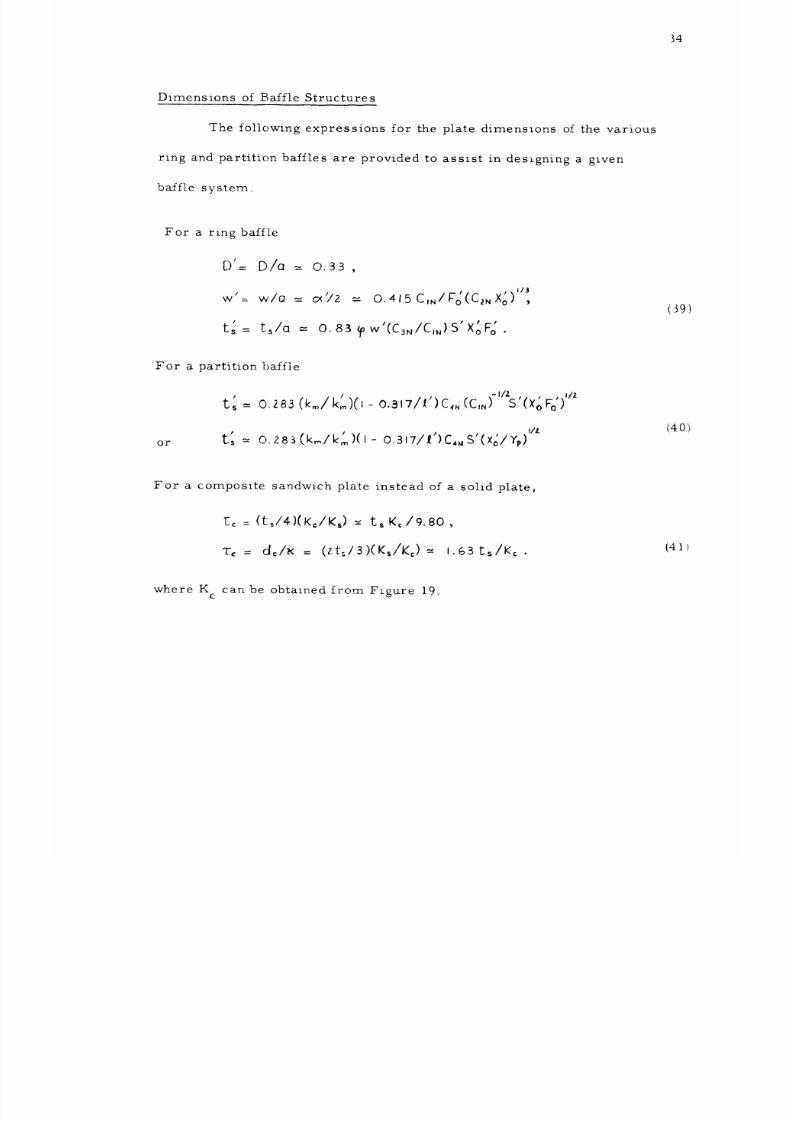
Dimensions of Baffle Structures
The following expressions for the plate dimensions of the various
ring and partition baffles are provided to assist in designing a glven
baffle system
For a ring baffle
D'= D/a = O.
33
,
l # #
w = w/a _- {_/Z = O,415CIN/Fo(C2NXo)
' XoF__/a = o.8B_ow (C_N/C,_}S'
' '
113
(39)
For a partition baffle
• -__ , _ )-,/_s, , ,.,1_
I/z
or t: -_ O,283(kmlI<_)(I- O.3171i')C4. S'(xolYp)
(40 ';
For a composite sandwich plate instead of a so].id plate,
t: = (toI4}(K:IK,)_-t_ K</9.80,
T_ = d:IK = (zt_I3)(K,/K:)-- i.G3r.s/K<.
(41
where K c can be obtained from Figure 19_
8/16/2019 Sloshing Nasa 2
http://slidepdf.com/reader/full/sloshing-nasa-2 41/81
35
ILLUSTRATIVE EXAMPLE
Problem Specifications
Consider the problem of designing a minimum weight baffle
system for the liquid propellant tanks shown in Figure Z0. _'_ The ap-
proximate dimensions of equivalent cylindrical tanks, as required for
this analysis, are _(I)--420 in for the fuel tank (i), _(Z)--- 720 in for
the oxidant tank (2), and a = 200 in for both tanks. Likewise, consid-
ering N' = 4 for the fuel tank,
n_,, : N/D/J_ = 4(66in)/(4ZO in) _- O._28 ,
and considering N' = 8 for the oxidant tank,
n_z ,
= 8(@6in)/(7Z0in)= 0.733,
Assume that the vehicle will undergo a range
of
axial accel-
erations from gl = 386 ips Z to gz = 3860 ips Z, that the range of ex-
citation frequencies (0_ 3_ f _ i. I cps) will include the first resonant
sloshing modes for the equivalent cylindrical tanks containing from
zero to eight partition baffles, and that the transverse displacement
amplitudes will never exceed X o = 2 in, which is equivalent to Xo'= 0.01.
Assume that the baffles are to be constructed from high-strength
aluminum alloy, having the properties E = 107psi, y = 0°3, S =6 x 10⁴psi,
This figure shows typical dimensions of the proposed S-IC booster
for the C-5 advanced Saturn space vehicle, as depicted on page 65
of[9].
8/16/2019 Sloshing Nasa 2
http://slidepdf.com/reader/full/sloshing-nasa-2 42/81
36
and _s= 259 x 10 -6 Ib-secZ/in 4, and that the liquid propellants have
the density of water,
rL =
93. 3 x 10 -6 lb-secZ/in 4. Because of the
considerable weight saving to be gained, assume that all baffles are
constructed from the type of composite sandwich plate described in
a previous section, for which
I/Z ,,
K_= 4(K/_:) [3(,-_)hmS/E] 'x"
Thus, for the fuel tank considered above,
K'c,_
where k m =
__ O. 81
p
= km (0.81)(Z..10)[(93.:3 x 10⁻⁶)(3860)(ZOO)/('6x 104 ) ]'/'
-" 0.0588 km ,
1 for nonperforated baffles, and where k m is obtained
from Figure 18 for perforated partition baffles having £ percentage
area removed° Similarly for the oxidant tank,
f
K(z )
--=0.1009 k m .
Assume, finally, that the ring baffles are simply supported
around their inside edges,
sloshing always occurs when h: = Zo 00.
propellant in eilher tank when h'= 2o 00,
h' 3
wL
=
[p,g,o ]
so that %o = I, and that the most severe
The total weight of liquid
is given by
= (3.14)(z.oo)[(93.3x lo9(38(,)(zoof]
= 1.81 x vO 6 lb.
8/16/2019 Sloshing Nasa 2
http://slidepdf.com/reader/full/sloshing-nasa-2 43/81
37
Weight Comparison of Various Baffle Systems
Basic weight equations. Substituting the values of the parame-
ters IZ', n _, K _, %0 , and Xo', specified above, into equations (30) and
(32c), the following expressions are obtained for the weights of the
various baffle systems which limit the first mode total force to some
maximum amp]it_de Fo_°
For the fuel tank_
/ t /31 f
Wr(i) = I,II
(io._,a") Ku)CrM _ n(,) (XO)'//F£
.
I/3 / _
"" I.II (8 x 10⁵)(0.0588)Cr-N(I)(O.6Z.8)(O.OI) /t- 0
' (Ib)
= 7000 CrN/Fo _
Wp(t)
t /
= o.za3(F,,,_,a")K(, ) Cp,,,(_- 0.317/l')(XoF/) '/_
--, 0. Z83 (8
x
I0s)(0.0588 km)CpN (0.849)(0.01Fo )'/'
/ I/Z
-.=
1130
k,.CpN
(F 0) ,
(Ib).
Similarly,
for the oxidant tank
w_(_)= 14, ooo C_./F o , (Ib),
Wp(z) --- 2_080 kmCpN(ro) '/z
(Ib)
•
Design weight of a ring baffle system°
liquid force amplitude to its design value,
or
By limitlng the total
as expressed by equation (33),
Fo*(d ) --- 0.27/X o ..-.- 0.27/0.01 : 27,
/ /
Fo(d) : (pL]zol 3) XoFg(a) _' (Z.88, IO")(O. Z7) "-"
778,000 Ib ,
8/16/2019 Sloshing Nasa 2
http://slidepdf.com/reader/full/sloshing-nasa-2 44/81
38
and by using Cr0 = Zo 01, obtained from Table l, the design weights of
plain (nonperforated) ring baffle systems for the two (uncom _artmented)
tanks specified above are found to be
Wrc, ) -- 7000 (2.01)/(27) - 521 lb ,
and
Wr(z} _- I042 lb.
The design damping provided by these ring baffles is determined from
equation (25a) to be
"_(d) = C,o/Fo --
1.33/27
=
0.049,
and the dimensions of these ring baffles are given by equations (39) as
D D 'a
= = 0.33 (ZOO) "-.' 66 in
,
W
t s =
tc
=
0.415ctC,o 0.415(zoo)(J.33) = 20.3 in
¢_ (CzoX_) '_3 = (z7)[(0.si)(o.ol)], /,
•
_ _ I/Z
, /
t
o8apw(c,olC,o)(p._2a/sJ %% = o.,6z rn,
tsKc/9.80
,-- (O.J6Z)(O.81)/9.80 --,
0.0134 in,
1.63
ts/Kc
= 1.63(0.16Z)/(0.81)= 0.,9,26 in.
Weights of perforated-partition baffle systems° Assume the
maximum damping that can be obtained from baffle systems composed
of 4, 6, and 8 perforated partitions when subjected to a maximum ex-
citation amplitude of X o' = 0. 01, is Yp= 0. 10,which agrees roughly
Thickness
oi
an equivalent strength solid plate.
Figure 19 shows the physical significance of these sandwich plate
dimensions.
8/16/2019 Sloshing Nasa 2
http://slidepdf.com/reader/full/sloshing-nasa-2 45/81
39
with data presented in [5] for N = 8 and E = 0o23. Figure 18 gives
k 1 = 1_ 09 corresponding to E = 0.23 for perforation holes centered
on an equilateral triangular lattice. Putting these values of dpand
k I into equation (25a} for the total iorce amplitude, into the weight
equations derived above, and into equations (40b) and (41) for tke plate
dimensions, the tol]owing table is obtained for each of N = 4, 6, and 8.
LIQUID FORCES WEIGHTS PLATE DIMENSIONS
N F o' F o ts tc T c ,dc
4
6
8
0
6.0
4°3
1.7
13o3
173, 000
124, 000
49, 000
383, 000
Wp (1) Wp (z)
8,420 15, 500
10,760 19,800
9,050 16,700
1,060 2, 120
0.976
0.830
0°524
0o171
0.081
O. O69
0_043
0,014
_': Equivalent damping ring baffle system (D = 66 in, w = 410 3 in)
Table 2o
Comparison of the liquid force amplitudes (lb), baffle
weights (lb), and plate dimensions (in), of perforated-
partition baffle s]{stems constructed from aluminum
alloy sandwich plates, necessary to withstand liquid
sloskir_g corresponding to Yv__.= 0. 10 and_X_ = 0.. 01
1.96
1.67
1.05
0.344
Weights of bai:fle systems composed_of bo_____th_ r_ ings and nonper ....
forated partitions. Equation 136) expresses the mimmum weight W T'
of a baffle system composed of both rings and nonperforated part_t_.ons_
necessary to witkstand liquid sloshing due to a maximum excitatlon
amplitude of Xo_ This value of minimum weight can be determ_ned
8/16/2019 Sloshing Nasa 2
http://slidepdf.com/reader/full/sloshing-nasa-2 46/81
4O
also by solving equation (35) for the liquid force amplitude F o'corres-
ponding to WT', and then substituting F o' into the above weight equations°
By so doing, and by using equations (39), (40), and (41) for the baffle
dimensions, _he io]lowlng tables are obtained for each of N = 4, 6, and 8.
TABLE 3: FUEL TANK (i)
N ¥
4
6
8
0 :_
0o 227
0. 266
0. 232
0.200
Fd
2°65
1.615
0.732
6.65
F o
76,3O0
46,500
21, i00
191,500
W r
2560
3030
2680
2120
Wp
5120
6060
535O
0
Wt
7680
9O9O
8030
2120
TABLE 4: OXIDANT TANK (2)
N ]' F o' F o W r Wp W%
4
6
8
0.214
0.252
0°200
0.200
2.80
1.706
0.774
6.65
80,600
49, 100
22,300
191,500
4850
5750
5060
424O
9,700
11, 500
10, 1ZO
0
Equivalent damping rlng baffle systems (D : 66 in)_
14, 550
17,250
15, 180
4,240
Tables 3 and 4,
Comparison of the liquid force amplitudes and
the minimum weights (ib) of ring/nonperforated-
partition baffle systems constructed from aluml-
hum alloy sandwich plate for X(_ : 0o 01.
8/16/2019 Sloshing Nasa 2
http://slidepdf.com/reader/full/sloshing-nasa-2 47/81
41
TABLE 5: FUEL TANK (i)
RING BAFFLES (N' = 4) PARTITION BAFFLES
N w ts tc Tc Tc
4
6
8
0 _
103. 3
127. 5
I16.0
82.6
0. 199
0. 209
0. 204
0.201
0,0165
0.0173
0.0161
0o0166
0.400
0.420
0. 392
O. 404
ts tc
0.457 0. 0378
0. 361 0. 0299
0.269 0.0206
0o919
0,725
0.413
TABLE 6: OXIDANT TANK (Z)
RING BAFFLES (N'= 8) PARTITION BAFFLES
N w ts tc Tc
98°0
121o0
II0.0
82.6
0. 196
O. 204
O. 190
0o 201
0. 0162
0. 0169
0. 0157
o. o166
0.394
0.410
0.382
0. 404
ts tc T c
0.505
0.400
0.264
:",,:Equivalent damping ring baffle
system
(D
=
66 in).
0.0417
0.0331
0,0218
Tables 5 and 6.
1..015
00 804
0. 530
Dimensions (in) of the minimum weight ring/non-
periorated-partition baffle structures,
The Overall Minimum Weight Baffle System
It is evident from the weight comparisons presented on the pre-
vious pages that for moderate suppression of the effects of liquid slosh-
ing, and for the partxcular parameters chosen in the present example,
8/16/2019 Sloshing Nasa 2
http://slidepdf.com/reader/full/sloshing-nasa-2 48/81
42
a baffle system composed exclusively of ring baffles (N = 0) will be far
lighter in weight than any of the systems which include partition baffles,
and thus would ordinarily be preferred over any of the partition baffle
systems° If only m_ld liquid suppression _s required, the overall mini-
mum weight baffle system is the plain "design" ring baffle system based
on the "design damping" defined on page 14, which for the present ex-
ample was found to be Yd = 0. 05. It should be noted, however, that the
liquid force amplitude, Fo'= 27, for this "design" ring baffle system,
resulting from an expected maximum first mode excitation amplitude of
Xo' = 0. 01, may be excessive, pending on the overall design requirements
of the rocket vehicle. If this is the case, the overall minimum weight
baffle system must be selected from the remaining baffle systems as
follows.
Both perforated-partition baffle systems and a plain ring baffle
system can be designed to provide damping of approximately Y= 0. 10,
which corresponds to moderate liquid suppression. Such a ring baffle
system was shown to be far lighter in weight (Wr:Wp_ l °10) than the
perforated-partition baffle systems (see Table Z). For the same
damping, however, the partition baffle systems result in significantly
less liquid force amplitude, particularly the eight-partition system
(Fr_Fp_ 8:1), and furthermore, the alterations in natural frequencies
provided by the partitions may compensate for the large differences
in baffle systems weight.
8/16/2019 Sloshing Nasa 2
http://slidepdf.com/reader/full/sloshing-nasa-2 49/81
45
If very strong suppression of liquid sloshing is required, a
baffle system composed of both rings and (nonperforated) partitions
should be considered. Tables 3 and 4 present comparisons of such
baffle systems, each of which provides the damping, _' -_0o20, nec-
essary to render its total weight WT a minimum. It is observed that
while the liquid force amplitudes resulting from the use of these ring/
nonperforated-partition baffle systems, are considerably less than for
any of the other baffle systems, their total weights are not excessive,
and are actually lighter than the perforated-partition baffles which
provide less liquid suppression. The arguments supporting the use
of perforated-partition baffles are therefore even more applicable for
the ring/nonperforated-partition baffle systems.
Baffle systems having six partitions weigh more in each instance
than those having four or eight partitions (due to the equivalent mechani-
cal model parameters used to represent the sloshing liquid for the various
baffle systems), and therefore are not to be recommended. Furthermore,
since the eight-partition baffle systems weigh approximately the same as
the four-partition baffle systems and yet provide considerably more llquid
suppression and considerably more control over liquid resonant frequen _
cies_ it is recommended that eight partitions be used whenever partltion-
ing is desirable, unless some other design requirement dictates the use
of four or six partitions.
8/16/2019 Sloshing Nasa 2
http://slidepdf.com/reader/full/sloshing-nasa-2 50/81
44
Since the dimensions of the sandwich plates are quite small,
particularly the skin thickness tc of the ring baffles, and therefore
difficult to manufacture, the use of solid plate baffle construction
might be preferred.
For baffles constructed from solid plate alumi-
num alloy, the corresponding weights would be approximately three
times those given in Tables Z, 3, and 4. It is interesting to note that
the thicknesses of the ring baffles remain essentially constant with
varying annular widths w, so that their weights are virtually in direct
proportion to w.
8/16/2019 Sloshing Nasa 2
http://slidepdf.com/reader/full/sloshing-nasa-2 51/81
45
CONCLUSIONS AND RECOMMENDATIONS
The foregoing analysis represents a preliminary investigation
of the problem of determining the optimum (sufficient damping - minimum
weight) baffle structure to be used in suppressing liquid sloshlng in the
propellant tanks of large rocket vehicles° For the typical propellant
tanks depicted in Figure 20, and for moderate liquid suppression, it
was shown that a plain ring baffle system will be far lighter in weight
than the baffle systems which include partition baffles. Since minimum
weight is the criterion for selecting a particular baffle system from
among those that provide sufficient damping, the plain ring baffle
system would ordinarily be selected for use in these tanks°
There are, however, three instances in which one of the per-
forated-partition baffle systems or one of the ring/nonperforated-
partition baffle systems (as compared in Tables 2-6) may possibly
be preferred ow_r a plain ring baffle system. (i) Partition baffles
may actually contribute to the axial buckling strength of the tank struc-_
ture -- an interaction neglected in the present analysis ..... and may
therefore result in a tank-baffle structure having less overall weight
than an uncompartmented tank with ring baffles. (2) The mimmum
weight ring- parl iti on baffle systems provide much stronger suppression
of liquid sloshing (smaller Fo') than is attainable with ring baffles alone,
and will therefore be preferred when such relatively strong hquid
8/16/2019 Sloshing Nasa 2
http://slidepdf.com/reader/full/sloshing-nasa-2 52/81
46
suppresslon is required. (3) Partitioning of a cylindrical tank consld-
erab]y alters the liquid natural frequencies. If the fundamental slosh-
ing frequency in an uncompartmented tank coincides with a critical
range of natural Jrequencies of the rocket structure or control system,
it may be possible to avoid liquid resonances in this critical frequency
range by the introduction of partition baffles°
Whenever the use of partition baffles is desired, a baffle sys-
tem having eight partitions is recommended over those having four or
six partitions, because the eight-partition system affords greater liquid
suppression and greater control of liquid resonant frequencies wlth very
little additional weight penalty. A baffle system composed exclusively
of nonperforated partition baffles is not to be recommended for use in
large rocket vehicles. Since the liquid damping is merely that pro-
vided by the viscous wiping of the liquid against the partitions and the
tank walls, and since for large propellant tanks (such as shown in
Fig-
ure Z0) this natural damping due to wiping is very small, the liquid
sloshing will necessarily become excessive for tank excitation at one
of the liquid resonant frequencles. Likewise, the use of perforated
ring baffles is not to be recommended, as the damplng effectiveness of
ring baffles decreases with increasing percentage perforation and as it
was shown that generally there is no weight saving to be gained by
perforation. _'_
_'.=See the discussion of strength-weight characteristics of perforated
plates presented on page 20°
8/16/2019 Sloshing Nasa 2
http://slidepdf.com/reader/full/sloshing-nasa-2 53/81
47
The analysis and results presented above are approximate to
the extent that certain of the functional relationships are not accurately
known, that some of the approximations used were extended beyond
their applicable ranges, and that certaln of the basic assumptions are
not strictly valid. It is suggested that future investigations pertaining
to the design of minimum weight antislosh baffle systems be concerned
with eliminating the existing inaccuracies and with generalizing the
present analysis to include a more liberal set of basic assumptions.
The principal inaccuracies in the present analysis are as follows_
Liquid sloshing anal_o The dependence of the sloshing ef-
fects (Fo', _', Pr', Pp') upon damping for liquid resonances in compart _-
mented tanks, as shown in Figures 10-13, was obtained in part from
experimental data, and in part by extrapolating from the known theoret.-
ical results for an uncompartmented tank. Expressions for these re-
lationships from the available theoretical hydrodynamic analysl.s [ 1 ]
would be valuab]eo Likewise, more complete experimental data for
compartmented tanks would be useful, especially _nvest_gatlons of the
six-partition tank and of'the slosh heights in compartmented tanks, for
which there is no existing experimental data. The first order approxi_
mations (25) used to represent the sloshing effects in the welght analy-
sis are valid only for small damping ( Y_ 0. 0Z), and should be replaced
by more accurate, higher order expressions, since the present concern
is with relatively large damping°
8/16/2019 Sloshing Nasa 2
http://slidepdf.com/reader/full/sloshing-nasa-2 54/81
48
Damping analysis° Further experimental studies are needed
for determining a more accurate relationship between the damping due
to a system of multiple ring baffles and the axial spacing of the rlngs0
Throughout the present analysis, the damping provided by a ring baffle
system is considered merely to be the contribution of the first sub-
merged baffle, as calculated from Miles' formula_ Damping calculated
by the above method appears to be in better agreement with experimen.
tal data than that obtained by superimposing the damping contributions
from each of the submerged ring baffles° Experimental results are
needed for determining analytic expressions for the damping provlded
by a system of perforated partition baffles and by a baffle system com-
posed of both rings and partitions. Likewise, tests are needed for de-
termining the influence of flexibility (finite deflections) of the tank and
baffle structures on the liquid damping, Finally, there is some question
as to whether the uniform damping introduced into the simple mechamcal
model used in this analysis is the same damping for each of the depend-
ent sloshing variables and for each of the various liquid resonances.
Bending moment analysis° The bending moment analysis could
be extended to include conical ring baffles, and the present analys_s
could be improved by using better approximatlons for the hydrodynamic
pressure loadings on the baffles at the various llquid resonances._ In
considering the strengths of the various baffle structures, the baiiles
8/16/2019 Sloshing Nasa 2
http://slidepdf.com/reader/full/sloshing-nasa-2 55/81
49
were assumed to be completely independent of deformations of the tank
wall, and vice versa. However, the baffles may actually tend to stiffen
the tank structure, as well as serving to damp the liquid sloshing. To
be more nearly correct, therefore, an analysis should be made which
includes the strength-weight characteristics of the entire tank-baffle
structures. A further interaction which should be investigated is the
mutual strengthening between the rings and partitions comprislng
ring/partition baffle systems such as shown in Figure I.
General. The present weight analysis is based on the assump-
tion that the baffles behave according to elastic thin plate theory. A
valuable contribution would be a weight analysis which assumes the
(ring) baffles to behave as large deflection membranes, and a strength
analysis based on plasticity theory. The present analysis could also
be extended to include additional tank compartmentation, such as the
inclusion of five, seven, nine, ten, and twelve partitions, and to in-
clude nonuniform spacing of the ring baffles. A suggested extension
of the present analysis is to consider a honeycomb baffle construction
consisting of perforated prismatic triangular or rectangular cells
repeated in each direction throughout the tank volume.
8/16/2019 Sloshing Nasa 2
http://slidepdf.com/reader/full/sloshing-nasa-2 56/81
5O
ACKNOWLEDGEMENTS
The writer wishes to extend thanks to Dr. H. N. Abramson
for his patient direction and encouragement of this work, to
Mro W. H. Chu for his assistance with mathematical details,
to Mr. Zuis R. Garza for providing and interpreting the ex-
perimental data, and to Mr. Gilbert F. Rivera and Mr0 David
DeArmond for preparing the figures. In addition, the writer
would also thank the personnel of the Southwest Research In-
stitute Computations Laboratory for their help in writing the
necessary computer programs, and to Mrs. Nancy Powell
for carefully typing the text.
8/16/2019 Sloshing Nasa 2
http://slidepdf.com/reader/full/sloshing-nasa-2 57/81
51
REFERENCES
I.
2_
o
.
,
a
7_
8_
9_
i0o
llo
Bauer, Ho F. , "Theory of Fluid Oscillations in Partially Filled
Cylindrical Containers", MTP-AERO-6Z-I, NASA Marshall
Space Flight Center, January 1962.
Abramson, Ho N., Chu, W. H., and Ransleben, G. E., Jr l,
"Representation of Fuel Sloshing in Cylindrical Tanks by an
Equivalent Mechanical Model", ARS Journal, 3_j_l,iZ, pp_ 1697-
1705, December 1961o
Miles, Jo W. _ "Ring Damping of Free Surface Oscillations in
a Circular Tank", Jo Applo Mecho, 24, ppo Z74-Z76 (1957)o
Abramson, Ho N°, Garza, Lo R,., and Kana, Do D0, "Liquid
Sloshing in Compartmental Cylindrical Tanks", ARS Journal,
32, ppo 978-980, June 1962o
Abramson, H. No, Chu, W. H., and Garza, Lo Ro, Liquid
Sloshing in 45 ° Sector Compartmented Cylindrical Tanks _ Tech_
Repro Noo 3, Contract Noo NAS8-1555, Southwest Research In-
stitute, November l, 1962o
Abramson, Ho No, and Ransleben, G. Eo, Jro, Wall Pressure
Distributions During Sloshing in Rigid Tanks , ARS Journal, 3_j_l_
pp. 545-547, April 1961.
Garza, Lo R., and Abramson, H. N., "Measurements of Liquid
Damping Provided by Ring Baffles in Cylindrical Tanks"_ Tech_
Repto No_ 5, Contract Noo NAS8-1555, Southwest Research In-
stitute, April I_ 1963o
Abramson, H_ No, "Theoretical and Experimental Studies of
Liquid Sloshing in Rigid Cylindrical Tanks", Final Report_ Con-
tract No. DA-23-072-ORD-1251, Southwest Research Institute,
May 15, 1961_
"Collected Papers on Instability of Shell Structures',' NASA Tech-
nical Note I)- 1510, Langley Research Center, December 196Zo
Timoshenko, So _ THEORY OF PLATES AND SHELLS, McGraw-
Hill Book Company, ]nc_, New York, (19401.
Stachiw, J. D._, "Welding of High Strength Aluminum Shells",
Undersea Technology, po 38, January 1963.
8/16/2019 Sloshing Nasa 2
http://slidepdf.com/reader/full/sloshing-nasa-2 58/81
52
Principal Variables
a
b
Cr
C m
CM N
Cp
C
s
d
d C
dp
Dp
D
E
E
m
F o
gl
gz
NOTATION
Radius of the cylindrical tank
Inside radius of a ring baffle
Hydrodynamic drag coefficient for normal sloshing
around a ring baffle
Coeflicient used in calculatlng the eqmvalent slosh _
ing masses from the resonant sloshing frequencies
Coefficients of the approximate relationships for
determining the sloshing effects
Coefflcient for adjusting the scale of the net pressure
across a partition baffle
Coefficient for adjusting the scale of the slosh helght
Depth of a single ring baffle beneath the liquid surface
Spacing between the square gridwork of a sandwlch
plate
Diameter of perforation holes in the baffle materlal
Spaclng between perloration holes in the baffle
material
Unlform axial spacing between rlng baffles
Young'_s elastic modulus for the baffle material
Percentage area of baffle material removed through
perforatlon
Total llquld force response due to transverse tank
excitatlon
Gr avitational acceleration
Maximum axial accel,erailon of the tank
8/16/2019 Sloshing Nasa 2
http://slidepdf.com/reader/full/sloshing-nasa-2 59/81
53
h
k
m
k =
m (km)l/2
k; = 1 -
m m
k _T
m
K n
M k
m k = (Mk)ma x
m T = _r_La2h
mi
m o
N
N _
Nil
Pk
Pk = (Pk)max
r, z, @
S
t c
t s
Average depth of liquid below the free surface
Plate perforation factor
Plate perforation fraction
Plate load bearing area ratio (due to perforation)
Plate cross-section coefficient
Length of the cylindrical tank
Bending moment distribution throughout a baffle
structure due to the maximum pressure loading Pk
Overall maximum bending moment occurring in a
baffle structure
Total mass of liquid contained in the cylindrical tank
Equivalent mass associated with the _th sloshing mode
Equivalent rigid liquid mass
Number of tank compartments (partitions)
Total number of ring baffles
Number of submerged ring baffles for a given h and D
Maximum instantaneous net pressure distribution over
a baffle system
Overall maximum net pressure actlng across a bafile
structure
Cylindrical coordinates
Characteristic ultimate strength of the baffle materlal
Skin thickness of a simple composite sandwich plate
Thickness of a solid plate
8/16/2019 Sloshing Nasa 2
http://slidepdf.com/reader/full/sloshing-nasa-2 60/81
54
Wk
w
X o
cxi,_i , etc.
cx_
Zn
eL
£B
(F'ma x
r_ C
V
W
co i
Kt c
Total weight of a baffle system
Annular width of a ring baffle
Displacement amplitude of the transverse tank
excitation
General variables used in various formulas
Fraction of the tank cross-sectional area blocked
by a ring baffle
Total damping factor (g = logarithmic decrement)
Design damping provided by a system of ring baffles,
where -_d = D/2
Specific weight (per unit area) of a plate material
Mass density of the contained liquid
Mass density of the baffle material
Maximum stress induced in a baffle structure by
the maximum bending moment m k
Overall thickness of a simple composite sandwich
plate
Poisson's ratio for the baffle material
Angular frequency of the transverse tank excitation
ith lowest natural sloshing (angular) frequency
Thickness of sandwich plate gridwork material
Amplitude of the liquid free surface oscillations at
the tank wall (slosh height)
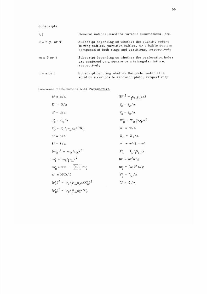
8/16/2019 Sloshing Nasa 2
http://slidepdf.com/reader/full/sloshing-nasa-2 61/81
55
Subscripts
i,j
k = r, p, or T
m:0or I
n=sorc
General indices; used for various summations_ etCo
Subscript depending on whether the quantity refers
to ring baffles, partition baffles, or a baffle system
composed of both rings and partitions, respective[_y
Subscript depending on whether the perioration holes
are centered on a square or a triangular lattice,
respectively
Subscript denoting whether the plate material is
solid or a composite sandwich plate, respectively
Convenient Nondimensional Parameters
b' = b/a
D: = D/a
d'= d/a
d'= dc/a
c
, 3 ,
F o = Fo/#)Lg2a X o
h' - h/a
f.'=
(m{<)2 = rnk/Pka2
m 1 = mi/_LaZ
m' = Trh' ,,- m
o l 1
n' = N'D/
(Pr) 2 = Pr/_Lg2a(Xo )2
(pp)2 = pp/fLgzaXo
(S') z
= ioLgZa/S
, = tc/ac
t' = t s/a
s
W{<= Wk/_._,a3
W _ _ w/a
X o = Xo/a
cx = w'(Z - w')
W' = mZal g
co = (Cui)2a/g
1
T' = T /a
c c
._'= Gla
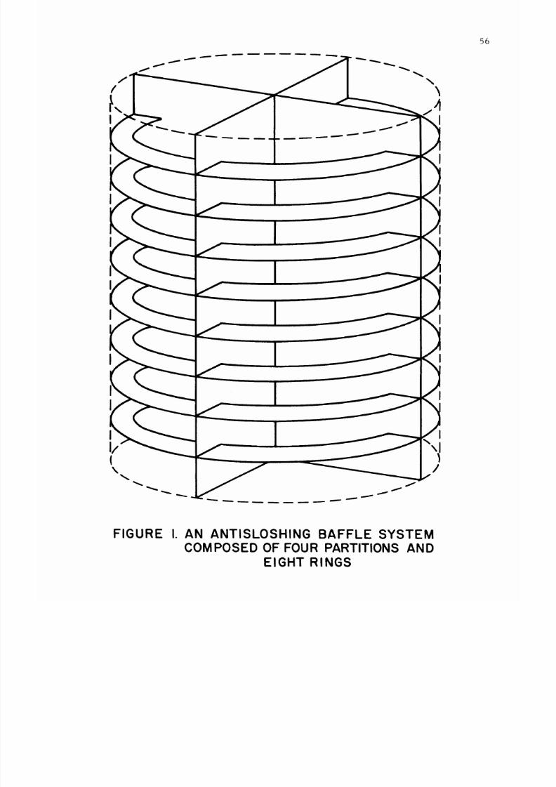
8/16/2019 Sloshing Nasa 2
http://slidepdf.com/reader/full/sloshing-nasa-2 62/81
\
I
56
I
(
\
FIGURE I. AN ANTISLOSHING BAFFLE SYSTEM
COMPOSED OF FOUR PARTITIONS AND
EIGHT RINGS
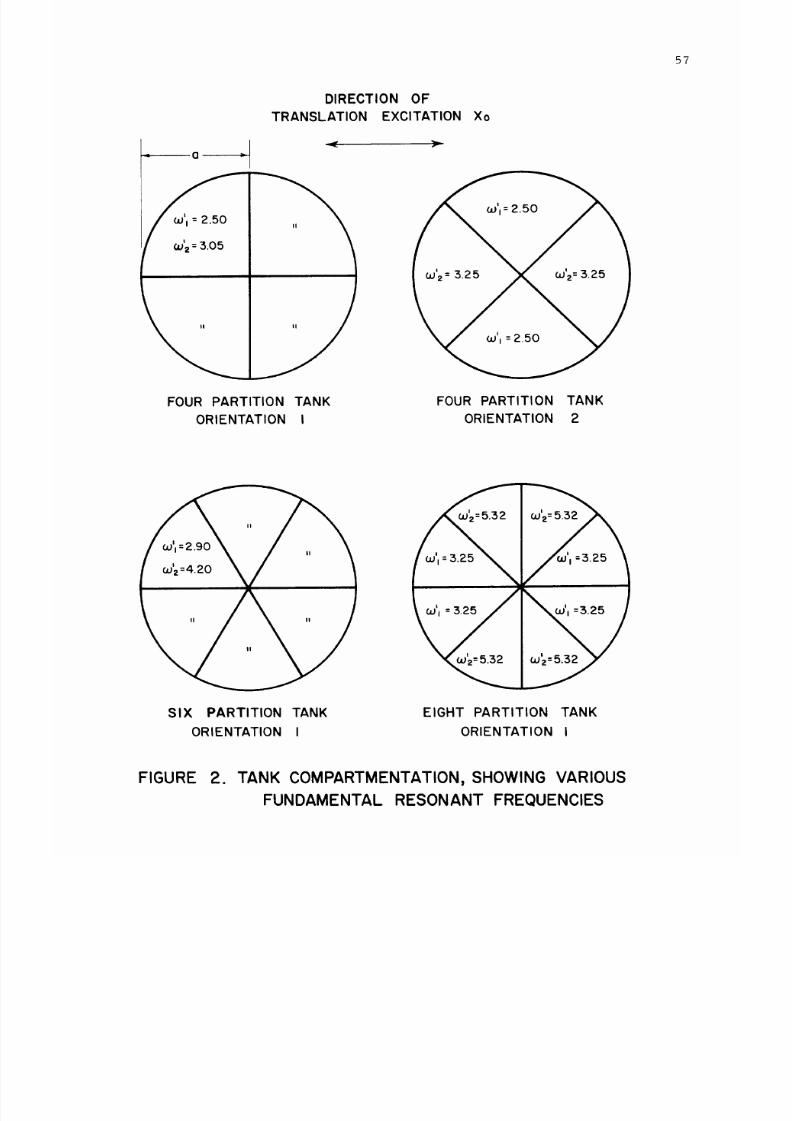
8/16/2019 Sloshing Nasa 2
http://slidepdf.com/reader/full/sloshing-nasa-2 63/81
5"7
DIRECTION OF
TRANSLATION EXCITATION Xo
_'z =
3.O
5
II
FOUR PARTITION TANK
ORIENTATION I
FOUR PARTITION TANK
ORIENTATION 2
SIX PARTITION TANK
ORIENTATION
I
O.Ill
EIGHT PARTITION TANK
ORIENTATION I
FIGURE
2.
TANK COMPARTMENTATION, SHOWING VARIOUS
FUNDAMENTAL RESONANT FREQUENCIES
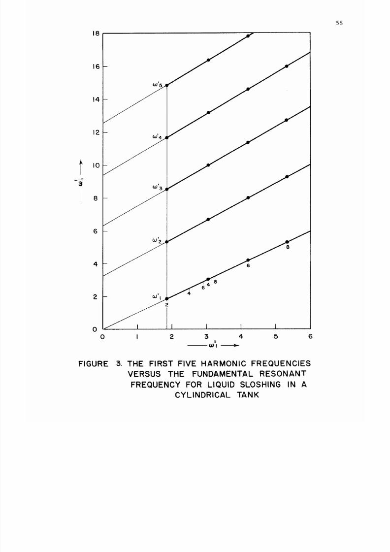
8/16/2019 Sloshing Nasa 2
http://slidepdf.com/reader/full/sloshing-nasa-2 64/81
18
16
14
12
I0
8
6
4
2
4
I I
1
0 I 2 3 4 5 6
I
58
FIGURE
5°
THE FIRST FIVE
HARMONIC FREQUENCIES
VERSUS THE FUNDAMENTAL RESONANT
FREQUENCY FOR LIQUID SLOSHING IN A
CYLINDRICAL TANK
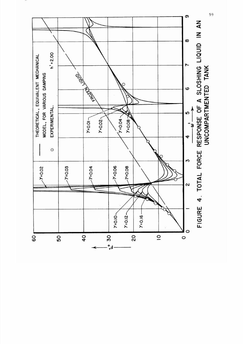
8/16/2019 Sloshing Nasa 2
http://slidepdf.com/reader/full/sloshing-nasa-2 65/81
0
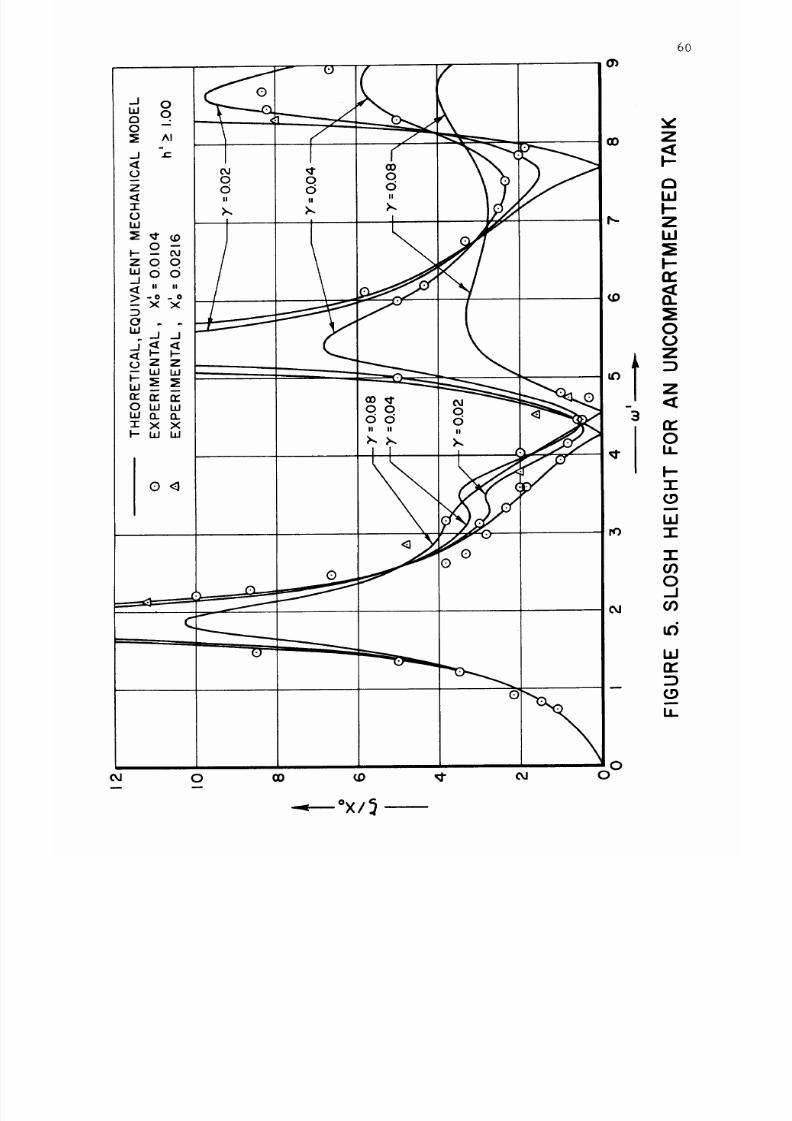
8/16/2019 Sloshing Nasa 2
http://slidepdf.com/reader/full/sloshing-nasa-2 66/81
o 0 . v
0 --
_AI i L
-- 12) 0
z d d .'--:
,i_ II II
,._o_
/
\
zoo
/
\
" "
/
\
5 x× / ____- '
.J<,<
_ w I..iJ __ it.)
0 W I..U
"rxx
i
I- la.J W
/
, 0 < W
, _-
60
0
oa 0
(.9
i
b_
-_--- °X/_
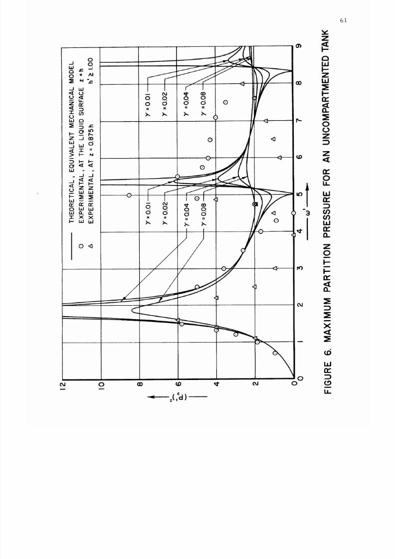
8/16/2019 Sloshing Nasa 2
http://slidepdf.com/reader/full/sloshing-nasa-2 67/81
61
v
Z
oJ 0 cO
D
_" oJ
d
= z(,¢l)--
0
0
W
OC
,(.9
B
LI..
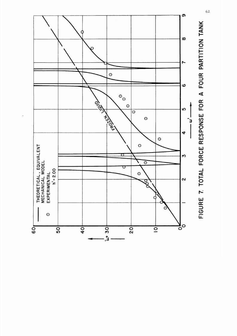
8/16/2019 Sloshing Nasa 2
http://slidepdf.com/reader/full/sloshing-nasa-2 68/81
\
\
\
%
=__
_ oo
:E
J
0
rr ._ rr
01"i,1
1,1 00.
-1-I,1x
o
\ o
(D
D-
QD
IV)
N
0
0
0
0
0
0 0
O-
D 6") _ IV) OJ --
t
-3
6Z
Z
Z
0
m
n-
n-
o
n-
o
u_
W
c_
Z
0
a.
c_
ILl
rr
W
(0
n-
O
U_
.J
0
D_
W
n-
b_
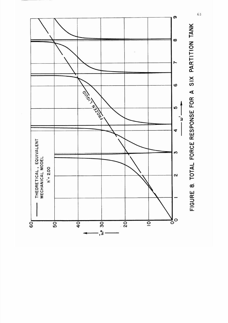
8/16/2019 Sloshing Nasa 2
http://slidepdf.com/reader/full/sloshing-nasa-2 69/81
i--
Z
u..I
J
>
:::D d
OrW
W_
I
_ _o _.,=
uJ Z
n-<[
0 1
uJO
I
uJ
O O O O O O
U) L'_ _I" rO oJ --
(n
(D
U)
ro
N
O
O
-3
Z
<[
Z
O
m
n-
<[
Cu
X
m
I)
<[
n-
O
U_
uJ
or)
Z
O
n
I)
i,i
n-
ILl
(D
n-
O
U_
.J
O
F-
tu
n-
(.9
U-
63
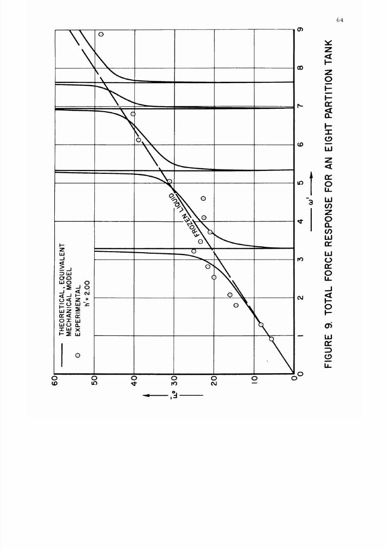
8/16/2019 Sloshing Nasa 2
http://slidepdf.com/reader/full/sloshing-nasa-2 70/81
O_
cO
v'
Z
I--
Z
0
k-
k-
I
_9
W
Z
64
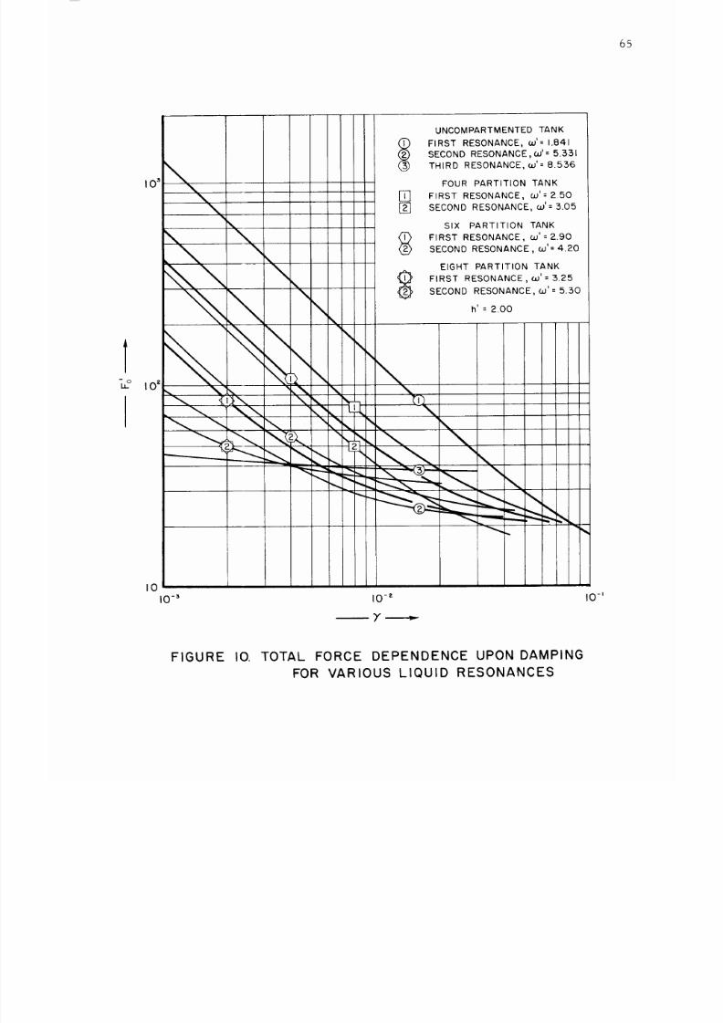
8/16/2019 Sloshing Nasa 2
http://slidepdf.com/reader/full/sloshing-nasa-2 71/81
65
I0
10-3
i0 -2
UNCOMPARTMENTED TANK
FIRST RESONANCE, w '= 1.841
I_
SECOND RESONANCE,CO - 5.531
THIRD RESONANCE, CO'= 8.556
FOUR PARTITION TANK
[] FIRST RESONANCE, w'= 2.50
[] SECOND RESONANCE, co'= 5.05
SIX PARTITION TANK
FIRST RESONANCE, co'= 2.90
SECOND RESONANCE, co' = 4.20
EIGHT PARTITION TANK
FIRST RESONANCE, co' = :5.25ECOND RESONANCE, co' = 5.:50
h' = 2.00
I0-'
FIGURE IO. TOTAL FORCE DEPENDENCE UPON DAMPING
FOR VARIOUS LIQUID RESONANCES
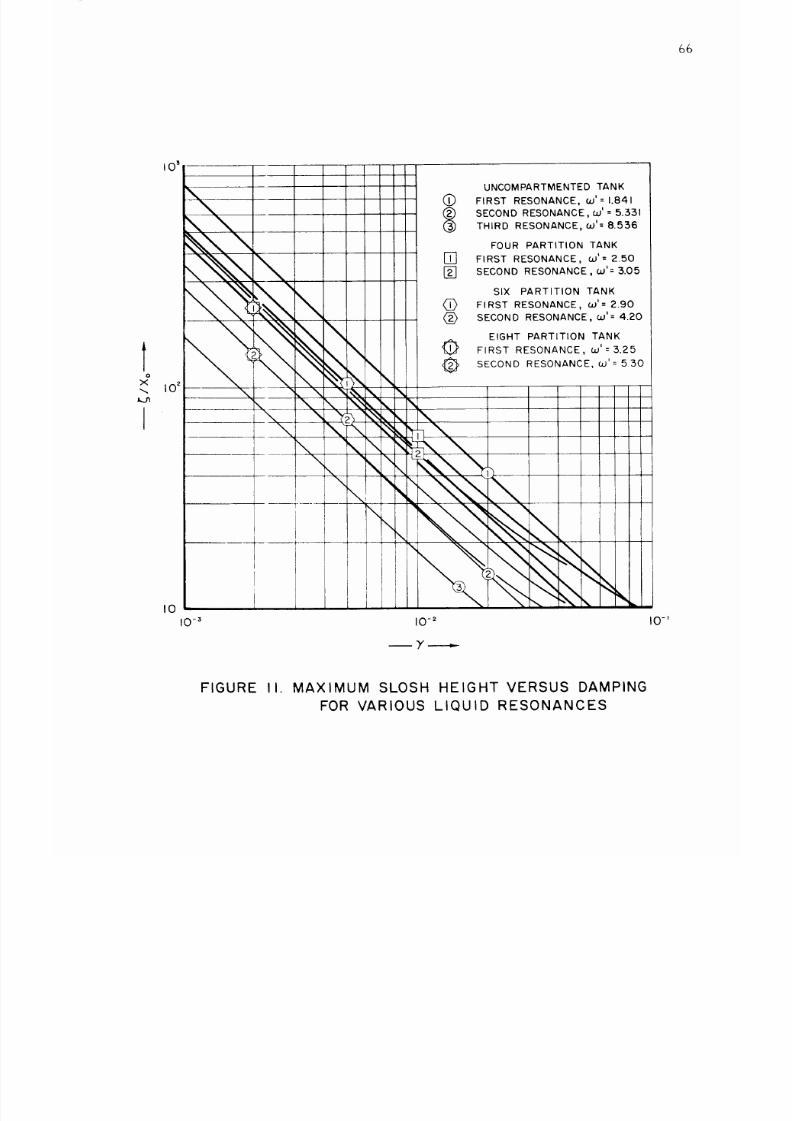
8/16/2019 Sloshing Nasa 2
http://slidepdf.com/reader/full/sloshing-nasa-2 72/81
66
o
x
J
UNCOMPARTMENTED TANK
(_ FIRST RESONANCE, co'=1.841
SECOND RESONANCE, co' = 5.331
HIRD RESONANCE, co'=8.536
FOUR PARTITION TANK
[] FIRST RESONANCE, oJ'= 2.50
[] SECOND RESONANCE,co'= 3.05
SIX PARTITION TANK
_> FIRST RESONANCE, co'= 2.90
(_ SECOND RESONANCE, co'= 4.20
EIGHT PARTITION TANK
FIRST RESONANCE, co'= 3.25
SECOND RESONANCE, co'= 550
FIGURE II. MAXIMUM SLOSH HEIGHT VERSUS DAMPING
FOR VARIOUS LIQUID RESONANCES
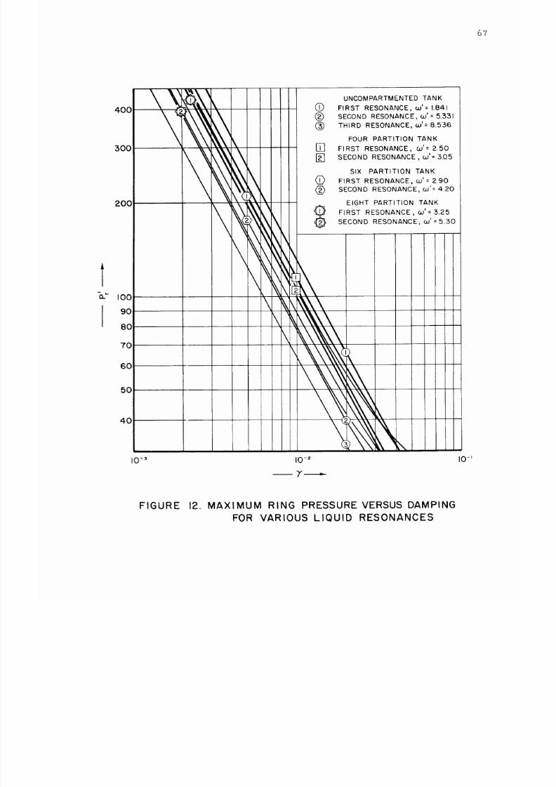
8/16/2019 Sloshing Nasa 2
http://slidepdf.com/reader/full/sloshing-nasa-2 73/81
67
I
4OO
300
2OO
I00
90
8O
7O
60
50
40
\
\
\
\
\
@
®
®
[]
[]
@
®
S
\
\%\\
_\\\\\
k\\\\\
_,\\\\\q
UNCOMPARTMENTED TANK
FIRST RESONANCE, co'= 1.841
SECOND RESONANCE, 6o'= 5.331
THIRD RESONANCE, co'= 8.536
FOUR PARTITION TANK
FIRST RESONANCE, co'= 2.50
SECOND RESONANCE, co'=5.05
SIX PARTITION TANK
FIRST RESONANCE, co' = 2.90
SECOND RESONANCE, co'= 4.20
EIGHT PARTITION TANK
FIRST RESONANCE, co'=3.25
SECOND RESONANCE, co' =5,30
I0 -3 I0 -2 I0-'
FIGURE 12. MAXIMUM RING PRESSURE VERSUS DAMPING
FOR VARIOUS LIQUID RESONANCES
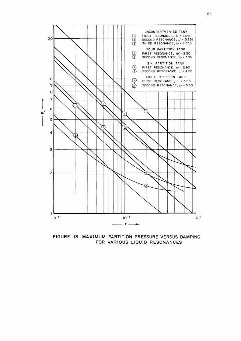
8/16/2019 Sloshing Nasa 2
http://slidepdf.com/reader/full/sloshing-nasa-2 74/81
68
20
I0
9
8
7
6
5
4
3
2
UNCOMPARTMENTED TANK
0 FIRST RESONANCE, co'= 1.841
(_ SECOND RESONANCE, co' = 5.331
(_) THIRD RESONANCE, co'= 8.536
FOUR PARTITION TANK
[] FIRST RESONANCE, co'= 2.50
[] SECOND RESONANCE, co'=3.05
SIX PARTITION TANK
(_ FIRST RESONANCE, co'= 2.90
<_ SECOND RESONANCE, co'= 4.20
EIGHT PARTITION TANK
FIRST RESONANCE, co'= 3.25
SECOND RESONANCE, co'= 5.50
I
10-3 I0 -2 IO-J
FIGURE 13. MAXIMUM PARTITION PRESSURE VERSUS DAMPING
FOR VARIOUS LIQUID RESONANCES
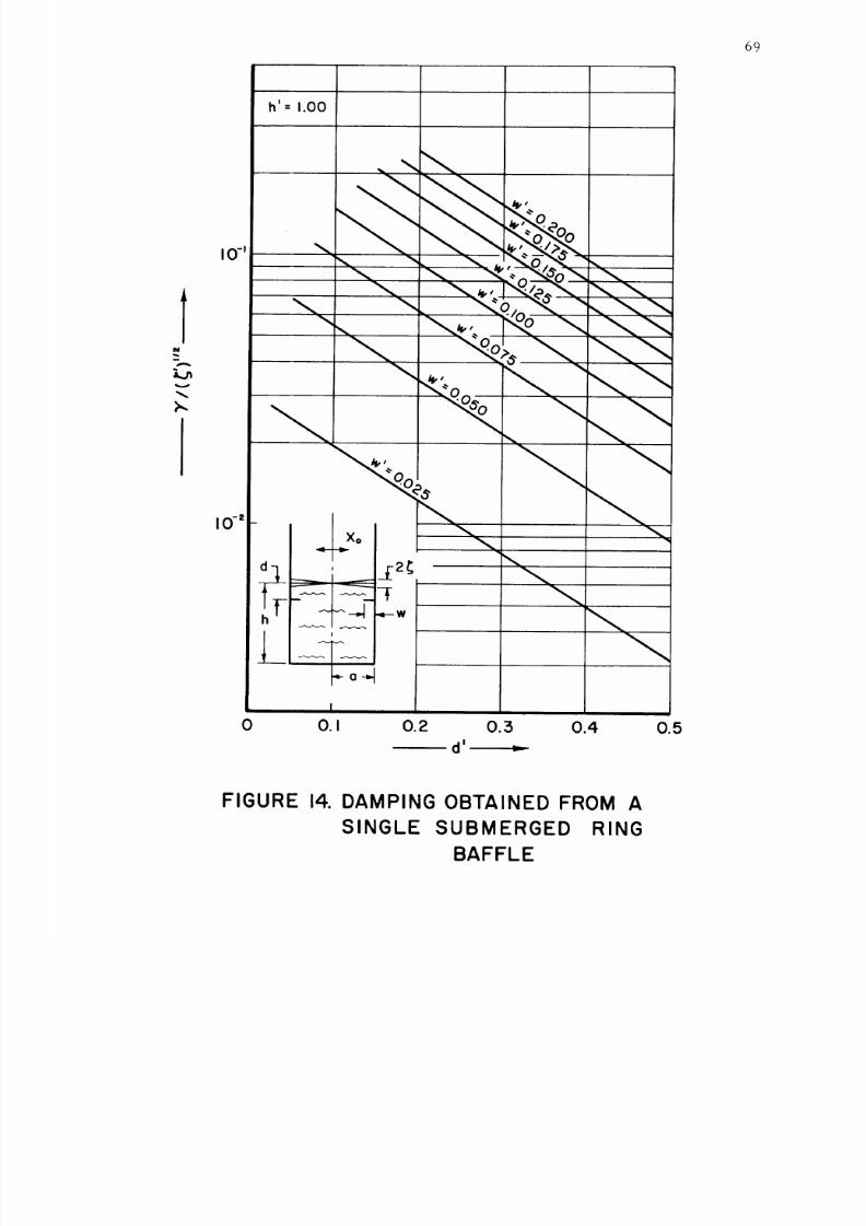
8/16/2019 Sloshing Nasa 2
http://slidepdf.com/reader/full/sloshing-nasa-2 75/81
69
h'=
1.00
N
I0 -
I0 -=
" \ \ \ "<Oo'<_o\'_
l I
I
0 0.1 0.2 0.3 0.4
d'
0.5
FIGURE 14. DAMPING OBTAINED FROM A
SINGLE SUBMERGED RING
BAFFLE
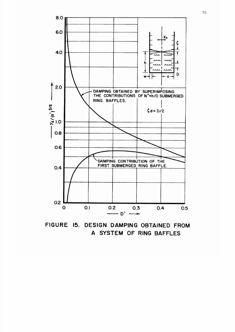
8/16/2019 Sloshing Nasa 2
http://slidepdf.com/reader/full/sloshing-nasa-2 76/81
8.0
7O
6.0
4..0
2.0
OJ
A
0.8
0.6
0.4
0.2_
0 0.1
-- Xo -
I
7-
_JL
_ i .__ F
*_t_ -°-'1°
I
-" DAMPING OBTAINED BY SUPERIMPOSING
THE CONTRIBUTIONS OF N h/D SUBMERGED
RING BAFFLES.
c_d=D/2
_,_PT'_O_;,_U,O_O_H_--_--
0.2 0.3 0.4 0.5
_D I
FIGURE 15.
DESIGN DAMPING OBTAINED FROM
A SYSTEM OF RING BAFFLES
8/16/2019 Sloshing Nasa 2
http://slidepdf.com/reader/full/sloshing-nasa-2 77/81
1
E
0.30
0.25
0.20
0.15
0.10
0.05
v=0.3
/
...=7
'
_1 _-/ z
_/ <_1 -- ° :-
14/ , _ t---- ..... ----. _,
I
_/ _--_-_-r , .:.--:
ll/,,,Ir_r , ,,_'
h'
0 I
0 0.2 0.4 0.6 0.8 1.0
I
W
FIGURE 16. MAXIMUM BENDING MOMENT FOR A
RING BAFFLE CLAMPED AROUND r=o,
AND SUBJECT TO A UNIFORM TRANSVERSE
PRESSURE LOADING
71
8/16/2019 Sloshing Nasa 2
http://slidepdf.com/reader/full/sloshing-nasa-2 78/81
0.:5
0.2
t
O.
m
E
0.1
0
I
FIGURE
/-
I
h_-X
5:5 4
I
I -----_
17. MAXIMUM BENDING MOMENT FOR
6
A PARTITION BAFFLE, CLAMPED AT
r=O, o AND SIMPLY SUPPORTED AT
z=O, £, AND SUBJECT TO A HYDRO-
STATIC TRANSVERSE PRESSURE
LOADING.
O0
72
8/16/2019 Sloshing Nasa 2
http://slidepdf.com/reader/full/sloshing-nasa-2 79/81
73
1.4
1.2
1.0
t 0.8
E
0.6
0.4
0.2
0
0
FIGURE 18.
ko (,SQUARE LATTICE OF HOLES)
_ .
-- Dp--,,
-
.°--4 _-
SQUARE LATTICE
OF HOLES
TRIANGULAR LATTICE
OF HOLES
I
0.1 0.2 0.3 0.4 0.5
PLATE PERFORATION FACTORS
VERSUS PERCENTAGE AREA
REMOVED
8/16/2019 Sloshing Nasa 2
http://slidepdf.com/reader/full/sloshing-nasa-2 80/81
74
0.9
0.8
0.7
0.2
0.1
0
0
/
tc
2 4 6 8 I0
2
Jl
K krn S/Ex10 3
FIGURE 19. CROSS SECTION FACTOR FOR A SIMPLE
COMPOSITE SANDWICH PLATE
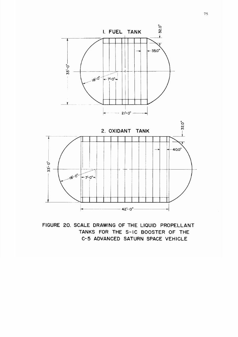
8/16/2019 Sloshing Nasa 2
http://slidepdf.com/reader/full/sloshing-nasa-2 81/81
?5
=o
_1
tO
tO
I. FUEL
TANK
0
I
tO
i
i . .. ..
_-7'-0'_
1
l
--- 2 ILo ....
2.
OXIDANT TANK
(M
°
(M
tO