slo-syn md808 & md808-128 microstep drive module ......to 1/100 microstep. the md808-128 can be...
TRANSCRIPT

www.DanaherMotion.com
SLO-SYN® MD808 & MD808-128 Microstep Drive Module Installation Instructions
Document Number: 400030-145
Rev E

Record of Manual Revisions ISSUE NO. DATE BRIEF DESCRIPTION OF REVISION
A 06/26/99 Initial release B 02/10/00 Revise corporate identity C 10/05/01 Revise corporate identity D 01/15/03 Updated contact information and revise corporate identity E 07/31/03 Updated corporate style
Copyright Information © Copyright 1997 - 2003 Danaher Motion - All rights reserved. Printed in the United States of America.
NOTICE: Not for use or disclosure outside of Danaher Motion except under written agreement. All rights are reserved. No part of this book shall be reproduced, stored in retrieval form, or transmitted by any means, electronic, mechanical, photocopying, recording, or otherwise without the written permission from the publisher. While every precaution has been taken in the preparation of the book, the publisher assumes no responsibility for errors or omissions. Neither is any liability assumed for damages resulting from the use of the information contained herein.
This document is proprietary information of Danaher Motion that is furnished for customer use ONLY. No other uses are authorized without written permission of Danaher Motion. Information in this document is subject to change without notice and does not represent a commitment on the part of Danaher Motion. Therefore, information contained in this manual may be updated from time-to-time due to product improvements, etc., and may not conform in every respect to former issues.
SAFETY The equipment described herein has been developed, produced, tested and documented in accordance with the corresponding standards. Use conforming with requirements means that the safety recommendations and warnings detailed in this manual are complied with and applicable regulations for safety (machine directives, etc.) and noise suppression (EMC Directives) are observed while operating the drive. Comply with the applicable European standards and Directives. At the end of its lifetime, dispose of or recycle the drive according to the applicable regulations.
This unit is designed for 20 to 80 VDC input only.
Installation and wiring of the drive must be completed only by qualified personnel having a basic knowledge of electronics, installation of electronic and mechanical components, and all applicable wiring regulations.
The "PWR ON" LED must be off for approximately 30 seconds before making or breaking the motor connections. Motors powered by this drive may develop extremely high torque. Be sure to disconnect power to this drive before doing any mechanical work.
Commissioning of the machine utilizing the drives must be done only by qualified personnel having a broad knowledge of electronics and motion control technology.
As the user or person applying this unit, you are responsible for determining the suitability of this product for the application. In no event is Danaher Motion responsible or liable for indirect or consequential damage resulting from the misuse of this product.

Danaher Motion Superior Electric Table of Contents
SLO-SYN MD808 & MD808-128 i
Table of Contents
1. INTRODUCTION..........................................................................1-1
1.1. IN THIS MANUAL....................................................................1-11.2. FEATURES...............................................................................1-2
2. EXPRESS START UP...................................................................2-1
3. INSTALLATION GUIDELINES..................................................3-1
3.1. MOUNTING ..........................................................................3-13.1.1. Mounting Dimensions ......................................................3-1
3.2. CONNECTORS AND PIN ASSIGNMENTS .......................3-23.2.1. MOTOR CONNECTIONS................................................3-33.2.2. POWER INPUT................................................................3-5
4. SPECIFICATIONS ........................................................................4-1
4.1. MECHANICAL SPECIFICATIONS.....................................4-14.2. ELECTRICAL SPECIFICATIONS.......................................4-14.3. ENVIRONMENTAL SPECIFICATIONS.............................4-14.4. MOTOR COMPATIBILITY .................................................4-24.5. PREFERRED MOTORS........................................................4-34.6. CURRENT AND STEP RESOLUTION SETTINGS ...........4-4
4.6.1. Current Settings (Switch Positions 1 – 5) ........................4-44.6.2. Step Resolution (Switch Positions 6 – 8)..........................4-5
4.7. AUTO REDUCE AND CONTROL FILTER SETTINGS.....................4-5
4.7.1. Auto Reduce (Switch Position 1)......................................4-54.7.2. Control Filter (Switch Positions 2 – 4) ............................4-6
4.8. SIGNAL SPECIFICATIONS.................................................4-64.8.1. Connector Pin Assignments .............................................4-64.8.2. Signal Descriptions ..........................................................4-74.8.3. Level Requirements ..........................................................4-84.8.4. Timing Requirements........................................................4-84.8.5. INDICATOR LIGHTS ....................................................4-10

Table of Contents Danaher Motion Superior Electric
ii SLO-SYN MD808 & MD808-128
5. TORQUE VERSUS SPEED CHARACTERISTICS.....................5-1
5.1. MOTOR PERFORMANCE...................................................5-1 5.2. TORQUE VERSUS SPEED CURVES..................................5-2
6. TROUBLESHOOTING.................................................................6-1
APPENDIX A.......................................................................................A-1
A.1 TROUBLESHOOTING ELECTRICAL INTERFERENCE PROBLEMS......................A-1 A.2 CUSTOMER SUPPORT/CONTACT INFORMATION .....................A-2

Danaher Motion Superior Electric Introduction
SLO-SYN MD808 & MD808-128 1-1
1. INTRODUCTION It is important that you understand how this SLO-SYN® MD808 Microstep Drive Module is installed and operated before you attempt to use it.
Read this manual completely before proceeding with the installation of this unit.
1.1. In This Manual This manual is an installation and operating guide to the SLO-SYN MD808 Microstep Drive Module. Section 1 gives an overview of the Drive and its features. Section 2 describes the steps necessary to place the drive into operation. General wiring guidelines as well as the physical mounting of the unit and connections to the drive portion are covered in Section 3.
Complete specifications, listed in Section 4, provide easily referenced information concerning electrical, mechanical, and environmental specifications. The procedure for setting the motor current level is also covered in this section.
Torque versus speed characteristics for the preferred SLO-SYN Stepper Motors are given in Section 5. Section 6, Troubleshooting, gives procedures to follow if the Microstep Drive Module fails to operate properly.
Appendix A provides procedures for troubleshooting electrical interference problems.

Introduction Danaher Motion Superior Electric
1-2 SLO-SYN MD808 & MD808-128
1.2. Features The SLO-SYN MD808 (MD808-128) is a bi-polar, speed-adjustable, two-phase PWM drive that uses power MOSFET devices. The MD808 can be set to operate a stepper motor in 8 step resolutions from full step to 1/100 microstep. The MD808-128 can be set to operate a stepper motor in 8 step resolutions from full step to 1/128 microsteps. The maximum running speed is 3,000 rpm. To reduce the possibility of electrical noise problems, the control signals are optically isolated from the drive circuit.
Active mid-range stabilization control
Switch selectable current levels of 3 through 8 amperes
Full short circuit protection (phase-to-phase and phase-to-ground)
Under-voltage and transient over-voltage protection
Thermal protection
Efficient thermal design
Optically isolated inputs
Reduce current input
Switch selectable automatic current reduction or externally activated current reduction
Windings off input
Switch selectable step resolution
Compact size
Sturdy all-aluminum case
Danaher Motion Superior Electric EXPRESS START UP
SLO-SYN MD808 & MD808-128 2-1
2. EXPRESS START UP The following instructions define the minimum steps necessary to make your Drive operational.
Always disconnect the power to the unit and be certain that the "PWR ON" LED is OFF before connecting or disconnecting the motor leads. FAILURE TO DO SO RESULTS IN A SHOCK HAZARD AND DAMAGES THE DRIVE.
Always operate the unit with the Motor and the Drive enclosure GROUNDED. Be sure to twist together the wires for each motor phase as well as those for the DC input. Six twists per foot is a good guideline.
1. Check to see that the motor used is compatible with the drive. Refer to Section 4.4 for a list of preferred motors.
2. Set the correct current level for the motor being used per the instructions in Section 4.6. Heat sinking is required if a current of 4 amperes or higher is used.
3. Select the appropriate step resolution and set the switches as described in Section 4.6.
4. Wire the motor per the "Motor Connections" description in Section 3.2.1.
5. Connect the power source to the DC input terminal strip. Be sure to follow the instructions for connecting the filter capacitor as described in Section 3.2.2, under Power Input.

EXPRESS START UP Danaher Motion Superior Electric
2-2 SLO-SYN MD808 & MD808-128
If the motor operates erratically, refer to Section 5, "TORQUE VERSUS SPEED CHARACTERISTICS."
Clockwise and counter-clockwise directions are properly oriented when viewing the motor from the end opposite the mounting flange.

Danaher Motion Superior Electric INSTALLATION GUIDELINES
SLO-SYN MD808 & MD808-128 3-1
3. INSTALLATION GUIDELINES
3.1. MOUNTING The SLO-SYN Drive is mounted by fastening its mounting brackets to a flat surface as shown in the next figure. If the Heat Sink Assembly (part number 221576-001) is mounted against a bulkhead, be sure to apply a thin coat of thermal compound between the heat sink and the mounting surface before fastening the unit in place. Do not use too much thermal compound. It is better to use too little than too much.
3.1.1. Mounting Dimensions
2.50
5.20 MAX0.07
5.25
0.66
1.36
0.313
0.219typical
4.84
Case temperature should not exceed +70° C (+158° F). A heat sink, such as Danaher Motion's Superior Electric Heat Sink Assembly (part number 221576-001) must be used when the drive is operated at a current setting of 4 amperes or more. In this case, the unit should be mounted upright (with the cooling fins vertical), or proper cooling will not occur. Airflow should not be obstructed. Forced air cooling may be required to maintain temperature within the stated limits.

INSTALLATION GUIDELINES Danaher Motion Superior Electric
3-2 SLO-SYN MD808 & MD808-128
When selecting a mounting location, it is important to leave at least two inches (51 mm) of space around the top, bottom and sides of the unit to allow proper airflow for cooling.
It is also important to keep the drive away from obvious sources of electrical noise. If possible, locate the drive in its own metal enclosure to shield it and its wiring from electrical noise sources. If this cannot be done, keep the drive at least three feet from any noise sources.
3.2. CONNECTORS AND PIN ASSIGNMENTS
The figure below shows the connector locations for the SLO-SYN MD808 Microstep Drive Module.

Danaher Motion Superior Electric INSTALLATION GUIDELINES
SLO-SYN MD808 & MD808-128 3-3
3.2.1. MOTOR CONNECTIONS
All motor connections are made via the 6-pin connector, part number 218397-006 (included). Pin assignments for this connector are given below. Motor connections are shown in the next figure.
PIN ASSIGNMENT
1 M1 (Phase A) 2 M3 (Phase A) 3 M4 (Phase B) 4 M5 (Phase B)
Motor phase A is M1 and M3 and motor phase B is M4 and M5. The motor frame must be grounded.
Cabling from the drive to the motor should be done with a shielded, twisted-pair cable. As a guideline, the wires for each motor phase should be twisted about six times per foot.
Danaher Motion offers the following motor cable configurations. These cables have unterminated leads on both ends.
Length Part Number
10 ft. (3 m) 216022-031 25 ft. (7.5 m) 216022-032 50 ft. (15.2 m) 216022-033
75 ft. (22.8 m) 216022-034
The next figure shows the possible motor wiring configurations.

INSTALLATION GUIDELINES Danaher Motion Superior Electric
3-4 SLO-SYN MD808 & MD808-128
D
F
B
H
5
4
1
3
WHITE/BLACK
BLACKWHITE/
RED
RED
GREEN
MOTOR TERMINAL "M" NUMBERSMOTORCONNECTOR PIN
MOTORCONNECTOR PIN
4-LEAD MOTORS
D
F
B
H
5
4
1
3
GREEN
WHITE/RED
RED
6-LEAD MOTORS
WHITE N.C.*E2G * N.C. BLACK
WHITE/GREEN
D
F
B
H
5
4
1
3
WHITE/BLACK
WHITE/RED
RED
8-LEAD MOTORS, SERIES CONNECTIONS
GBLACK
AWHITE
ORANGEE
GREEN
C
WHITE/GREEN
*6
2
7
8*
DRIVE PIN 1
DRIVE PIN 2
DRIVE PIN 1
DRIVE PIN 2
DRIVE PIN 1
DRIVE PIN 2
DRIVE PIN 4
DRIVE PIN 3
DRIVE PIN 4
DRIVE PIN 3
DRIVE PIN 4
DRIVE PIN 3
D
F
B
H
5
4
1
3WHITE/
RED
RED
8-LEAD MOTORS, PARALLEL CONNECTIONS
WHITE/BLACK
GBLACK
AWHITE
ORANGEE
C
6
2
7
8
GREEN
WHITE/GREEN
DRIVE PIN 4
DRIVE PIN 3
DRIVE PIN 1
DRIVE PIN 2
6
*These leads must be insulated and isolated from other leads or ground.
Circled letters identify terminals for connector motors; numbers identify those for terminal box motors.
Danaher Motion Superior Electric INSTALLATION GUIDELINES
SLO-SYN MD808 & MD808-128 3-5
3.2.2. POWER INPUT
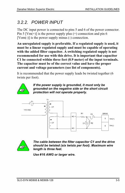
The DC input power is connected to pins 5 and 6 of the power connector. Pin 5 [Vm(+)] is the power supply plus (+) connection and pin 6 [Vom(-)] is the power supply minus (-) connection.
An unregulated supply is preferable. If a regulated supply is used, it must be a linear regulated supply and must be capable of operating with the added filter capacitor. A switching regulated supply is not recommended for use with this drive. It is important that capacitor C1 be connected within three feet (0.9 meter) of the input terminals. The capacitor must be of the correct value and have the proper current and voltage parameters (see list of components).
It is recommended that the power supply leads be twisted together (6 twists per foot).
If the power supply is grounded, it must only be grounded on the negative side or the short circuit protection will not operate properly.
115 VAC
F1T1
CT
CT
AC +
AC -
R1
C1+
R2
F2
5
6
DRIVE
Vm(+)
Vm(-)
The cable between the filter capacitor C1 and the drive should be twisted (six twists per foot). Maximum wire length is three feet.
Use #16 AWG or larger wire.

INSTALLATION GUIDELINES Danaher Motion Superior Electric
3-6 SLO-SYN MD808 & MD808-128
Components for circuit shown in previous figure:
5 ampere or lower setting
F1 3 amp time delay, Bussman MDA-3 or equivalent F2 15 amp very fast-acting, Bussman GBB-15 or
equivalent R1 5 Ω surge limiter, Phillips 2322-654-61508 or
equivalent R2 4.7 kΩ, 2 watt, ±5% T1 160 VA, Bicron Electronics BU216AS040D, Signal
Transformer 80-2 or equivalent BR1 General Instrument GBPC3502 or equivalent C1 4700 µf, 6.9 amp ripple current, 100 VDC United
ChemiCon 36DA472F100AL2A or equivalent
6 through 8 ampere setting
F1 6 amp time delay, Bussman MDA-6 or equivalent F2 15 amp very fast-acting, Bussman GBB-15 or
equivalent R1 4 Ω surge limiter, Phillips 2322-654-61408 or
equivalent R2 4.7 kΩ, 2 watt, ±5% T1 320 VA, Bicron Electronics BU233AS040D, Signal
Transformer 80-4 or equivalent BR1 General Instrument GBPC3502 or equivalent C1 6800 µf, 9.4 amp ripple current, 100 VDC United
ChemiCon 36DA682F100AD2A or equivalent

Danaher Motion Superior Electric SPECIFICATIONS
SLO-SYN MD808 & MD808-128 4-1
4. SPECIFICATIONS
4.1. MECHANICAL SPECIFICATIONS Size
(inches) 5.25 H x 1.36 W x 5.6 D (mm) 133 H x 35 W x 142 D
Weight 1.5 pounds (680 grams)
4.2. ELECTRICAL SPECIFICATIONS DC Input Range 20 VDC min., 80 VDC max. DC Current see Motor Table Drive Power Dissipation
(Worse Case) 40 watts
4.3. ENVIRONMENTAL SPECIFICATIONS Temperature
Operating +32° F to +122° F (0° C to +50° C) free air ambient, Natural Convection. Maximum heat sink temperature of +158° F (+70° C) must be maintained. Forced air cooling may be required.
Storage -40° F to +167° F (-40° C to +75° C) Humidity 95% max. non-condensing Altitude 6,562 feet (2000 m) max.

SPECIFICATIONS Danaher Motion Superior Electric
4-2 SLO-SYN MD808 & MD808-128
4.4. MOTOR COMPATIBILITY Motor Types Superior Electric M and KM Series
Frame Sizes M Series M061 (NEMA 23D) - M092 (NEMA 34) KM Series KML060 (NEMA 23) - KML093 (NEMA 34)
Number of Connections 4, 6, 8 Minimum Inductance 1 millihenry Maximum Resistance 0.25 x VDC Supply/I Setting Example:
VDC = 60 I Setting = 7
R max. = 0.25 x 60/7 = 2.1 Ω
Maximum resistance is total of motor plus cable.
Duty cycle limiting or external motor cooling may be required to keep the motor shell temperature below its rating.
Do not use larger frame size motor than those listed, or the drive may be damaged. If a larger frame size must be used, consult the factory for recommendations.

Danaher Motion Superior Electric SPECIFICATIONS
SLO-SYN MD808 & MD808-128 4-3
4.5. PREFERRED MOTORS Control Filter Switch Settings Power Supply Current
Motor
4
3
2
Current Setting (Amps)
Standstill (ADC)
Maximum (ADC)
KML060F05 DOWN UP UP 3 1.0 2.0
KML061F05 DOWN UP UP 3 1.0 2.0
KML062F07 DOWN UP UP 4 1.0 3.5
KML062F13 UP DOWN DOWN 8 1.5 4.5
KML063F07 DOWN UP UP 4 1.0 2.0
KML063F13* DOWN UP UP 8 2.0 4.5
KML091F07 DOWN UP UP 4 1.5 2.5
KML091F13* DOWN UP UP 8 1.5 4.0
KML092F13* DOWN UP UP 8 2.0 4.5
KML093F10 UP DOWN DOWN 7 2.0 4.5
KML093F14* UP DOWN DOWN 8 2.0 4.5
*Recommended motor
Power supply currents shown are measured at the output of the rectifier bridge.
Motors with windings other than those listed can be used as long as the current ratings listed on the motors are not exceeded.

SPECIFICATIONS Danaher Motion Superior Electric
4-4 SLO-SYN MD808 & MD808-128
4.6. CURRENT AND STEP RESOLUTION SETTINGS
4.6.1. Current Settings (Switch Positions 1 – 5) The proper current setting for each motor is shown on the torque vs. speed curves. Use this current level to obtain the torque shown. The access hole for the switches that set the motor current level is located on the back of the unit. Switches 1 through 5 are used to select a current level. Select the desired operating current by setting the appropriate switch. Only one switch should be Down at a time. If two or more switches are Down, the higher current level is the active level. The switch settings are:
Switch Position Peak Current (Amps) RMS Current (Amps)
All Up 3.0 2.1 1 Down 4.0* 2.8 2 Down 5.0* 3.5
3 Down 6.0* 4.2*
4 Down 7.0* 5.0* 5 Down 8.0* 5.6*
* Heat sinking is recommended at current settings of 4 amperes or higher. The drive case temperature MUST NOT exceed +70° C.

Danaher Motion Superior Electric SPECIFICATIONS
SLO-SYN MD808 & MD808-128 4-5
4.6.2. Step Resolution (Switch Positions 6 – 8) The number of pulses per revolution is selected using positions 6 through 8 of the switch. The following chart shows the correct switch settings for each available step resolution.
MD808 MD808-128
Switch* Position* Resolution Pulses/Ref Resolution Pulses/Ref
All Up Full 200 Full 200
7 Down 1/2 400 1/2 400
8 Down 1/5 1,000 1/4 800
7 & 8 Down 1/10 2,000 1/8 1,600
6 Down 1/20 4,000 1/16 3,200
6 & 7 Down 1/25 5,000 1/32 6,400
6 & 8 Down 1/50 10,000 1/64 12,800
6, 7, & 8 Down 1/100 20,000 1/128 25,600
* Switches not listed must be in the Up position
4.7. AUTO REDUCE AND CONTROL FILTER SETTINGS
4.7.1. Auto Reduce (Switch Position 1)
Refer to the next figure for the location of the Auto reduce switch.
Up - 50% Standstill current activated after 0.5 to 1.5 seconds. Down - Auto reduce inactive.
Reduce is controlled by an external signal.
1 2 3 4 5 6 7 8
4 3 2 1
Current Selection andStep Resolution Switches
Control Filter and AutoReduce Switches

SPECIFICATIONS Danaher Motion Superior Electric
4-6 SLO-SYN MD808 & MD808-128
4.7.2. Control Filter (Switch Positions 2 – 4)
Switch positions 2 through 4 set the control filter as indicated below:
SWITCH
4 3 2
FILTER FREQUENCY (Hz)
Down Down Down 1700
Down Down Up 850
Down Up Down 540
Down Up Up 420
Up Down Down 330
Up Down Up 270
Up Up Down 230
PO
SIT
ION
Up Up Up 200
Filter selection depends on the motor selected. See the list of recommended motors.
4.8. SIGNAL SPECIFICATIONS
4.8.1. Connector Pin Assignments All connections are made via the 5-pin connector, part number 221536-005.
Pin Assignment
1 OPTO
2 PULSE
3 DIR
4 AWO
5 RDCE

Danaher Motion Superior Electric SPECIFICATIONS
SLO-SYN MD808 & MD808-128 4-7
4.8.2. Signal Descriptions OPTO Opto-Isolator Supply. User supplied power for the opto-
isolators.
PULSE Pulse Input. A low to high transition on this pin advances the motor one step. Step size is determined by the Step Resolution switch setting.
DIR Direction Input. When this signal is high, motor rotation is clockwise. Rotation is counter-clockwise when this signal is low. Clockwise and counter-clockwise directions are properly oriented when viewing the motor from the end opposite the mounting flange.
AWO All Windings Off Input. When this signal is low, AC and DC current to the motor is zero.
There is no holding torque when the AWO signal is low.
RDCE Reduce Current Input. The motor current is 50% of the selected value when this signal is low.
Holding torque is also reduced when this signal is low.
If you are using the drive with an SS20001 or SS20001-V control, the READY input and the OPTO input on the control must be jumpered together.
SPECIFICATIONS Danaher Motion Superior Electric
4-8 SLO-SYN MD808 & MD808-128
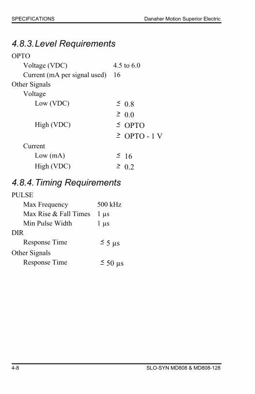
4.8.3. Level Requirements OPTO
Voltage (VDC) 4.5 to 6.0 Current (mA per signal used) 16
Other Signals Voltage
Low (VDC) < 0.8 > 0.0 High (VDC) < OPTO
> OPTO - 1 V Current
Low (mA) < 16 High (VDC) > 0.2
4.8.4. Timing Requirements PULSE
Max Frequency 500 kHz Max Rise & Fall Times 1 µs Min Pulse Width 1 µs
DIR Response Time < 5 µs
Other Signals Response Time < 50 µs

Danaher Motion Superior Electric SPECIFICATIONS
SLO-SYN MD808 & MD808-128 4-9
4.5 - 6.0 VDC, 16 mA PER SIGNALOPTO
PULSE
DRIVE
CONTROL SIGNAL
TTL
7406
5VOPTO
PULSE
DRIVE SWITCH
OPTO 5V GND
OPTO
PULSE
DRIVE
550 ohms
1/4 watt
12 VDC, 16 mA PER SIGNAL
CONTROL SIGNAL
CONTROL LOGIC COMMON
4.5 - 6.0 VDC, 16 mA PER SIGNALOPTO
PULSE
DRIVECONTROL SIGNAL
CONTROL LOGIC COMMON

SPECIFICATIONS Danaher Motion Superior Electric
4-10 SLO-SYN MD808 & MD808-128
4.8.5. INDICATOR LIGHTS "POWER" LED, Red
Lights when the drive logic power supply is present, indicating that the drive is energized.
"FAULT" LED, Red Lights to indicate over-current condition. This condition is a result of motor wiring errors or a ground fault. Lights to indicate the heat sink temperature has exceeded a safe level for reliable operation. Recovery from over-current or over-temperature condition requires removing and then reapplying the power.

Danaher Motion Superior Electric TORQUE VERSUS SPEED CHARACTERISTICS
SLO-SYN MD808 & MD808-128 5-1
5. TORQUE VERSUS SPEED CHARACTERISTICS
5.1. MOTOR PERFORMANCE All stepper motors exhibit instability at their natural frequency and harmonics of that frequency. Typically, this instability occurs at speeds between 50 and 1000 full steps per second and, depending on the dynamic motor load parameters, can cause excessive velocity modulation or improper positioning. The open area at the low end of each Torque vs. Speed curve represents this type of instability.
There are also other instabilities that may cause a loss of torque at stepping rates outside the range of natural resonance frequencies. One such instability is broadly defined as mid-range instability. Usually, the damping of the system and acceleration/deceleration through the resonance areas aid in reducing instability to a level that provides smooth shaft velocity and accurate positioning. If instability does cause unacceptable performance under actual operating conditions, the following techniques can be used to reduce velocity modulation.
1) Ensure that the control filter is set as shown in the motor table. If so, try changing the filter setting one or two frequency settings lower. If the results are worse, try setting the filter one or two frequency settings higher.
2) Avoid constant speed operation at the motor's unstable frequencies. Select a base speed that is above the motor's resonant frequencies and adjust acceleration and deceleration to move the motor through unstable regions quickly.
3) The motor winding current can be reduced. Lowering the current reduces torque proportionally. The reduced energy delivered to the motor can decrease velocity modulation.

TORQUE VERSUS SPEED CHARACTERISTICS Danaher Motion Superior Electric
5-2 SLO-SYN MD808 & MD808-128
4) Use microstepping to provide smoother operation and reduce the effects of mid-range instability.
Microstepping reduces the shaft speed for the given pulse input rate.
5.2. TORQUE VERSUS SPEED CURVES
The test conditions used when obtaining the torque versus speed data are listed in the lower left-hand corner of each curve.
70TORQUE - oz. in.
60
50
40
30
20
10
00 10 20 30 40 50
0
30 V
60 V
72 V
7.06
14.12
21.19
28.25
35.31
42.37
49.44Ncm
SPEED RPS
3.0 AMPS1/10 STEP0.262 lb-in**2
KML060F05 MOTOR, 3.0 Amp

Danaher Motion Superior Electric TORQUE VERSUS SPEED CHARACTERISTICS
SLO-SYN MD808 & MD808-128 5-3
150TORQUE - oz. in.
100
50
00 10 20 30 40 50
0
30 V
60 V
72 V
35.31
70.62
105.9
Ncm
SPEED RPS
3.0 AMPS1/10 STEP0.29 lb-in**2
KML061F05 MOTOR, 3.0 Amp

TORQUE VERSUS SPEED CHARACTERISTICS Danaher Motion Superior Electric
5-4 SLO-SYN MD808 & MD808-128
150
TORQUE - oz. in.
100
50
00 10 20 30 40 50
0
30 V
60 V
72 V
35.31
70.62
105.9
Ncm
SPEED RPS
200
250
141.2
176.6
4.0 AMPS1/10 STEP0.29 lb-in**2
KML062F07 MOTOR, 4.0 Amp

Danaher Motion Superior Electric TORQUE VERSUS SPEED CHARACTERISTICS
SLO-SYN MD808 & MD808-128 5-5
150
TORQUE - oz. in.
100
50
00 10 20 30 40 50
0
30 V
60 V
72 V
35.31
70.62
105.9
Ncm
SPEED RPS
200
250
141.2
176.6
8.0 AMPS1/10 STEP0.29 lb-in**2
KML062F13 MOTOR, 8.0 Amp

TORQUE VERSUS SPEED CHARACTERISTICS Danaher Motion Superior Electric
5-6 SLO-SYN MD808 & MD808-128
350TORQUE - oz. in.
300
250
200
150
100
50
00 5 10 15 20 25
0
30 V
60 V
72 V
35.31
70.62
105.9
141.2
176.6
211.9
247.29Ncm
SPEED RPS30
4.0 AMPS1/10 STEP0.29 lb-in**2
KML063F07 MOTOR, 4.0 Amp

Danaher Motion Superior Electric TORQUE VERSUS SPEED CHARACTERISTICS
SLO-SYN MD808 & MD808-128 5-7
350TORQUE - oz. in.
300
250
200
150
100
50
00 10 20 30 40 50
0
30 V
60 V
72 V
35.31
70.62
105.9
141.2
176.6
211.9
247.29Ncm
SPEED RPS
8.0 AMPS1/10 STEP0.29 lb-in**2
KML063F13 MOTOR, 8.0 Amp

TORQUE VERSUS SPEED CHARACTERISTICS Danaher Motion Superior Electric
5-8 SLO-SYN MD808 & MD808-128
350TORQUE - oz. in.
300
250
200
150
100
50
00 10 20 30 40 50
0
30 V
60 V
72 V
35.31
70.62
105.9
141.2
176.6
211.9
247.29Ncm
SPEED RPS
4.0 AMPS1/10 STEP0.29 lb-in**2
KML091F07 MOTOR, 4.0 Amp

Danaher Motion Superior Electric TORQUE VERSUS SPEED CHARACTERISTICS
SLO-SYN MD808 & MD808-128 5-9
350TORQUE - oz. in.
300
250
200
150
100
50
00 10 20 30 40 50
0
30 V
60 V
72 V
35.31
70.62
105.9
141.2
176.6
211.9
247.29Ncm
SPEED RPS
8.0 AMPS1/10 STEP0.29 lb-in**2
KML091F13 MOTOR, 8.0 Amp
800TORQUE - oz. in.
600
400
200
00 10 20 30 40 50
030 V
60 V
72 V
141.2
282.5
423.8
565.0Ncm
SPEED RPS
8.0 AMPS1/10 STEP0.29 lb-in**2
KML092F13 MOTOR, 8.0 Amp

TORQUE VERSUS SPEED CHARACTERISTICS Danaher Motion Superior Electric
5-10 SLO-SYN MD808 & MD808-128
1200TORQUE - oz. in.
800
400
00 5 10 20
030 V
60 V
72 V
282.5
565.0
847.4Ncm
SPEED RPS
7.0 AMPS1/2 STEP0.29 lb-in**2
200
600
1000
141.2
432.8
706.2
15
KML093F10 MOTOR, 7.0 Amp
TORQUE - oz. in.
800
400
00 5 10 20
030 V
60 V
72 V282.5
565.0
Ncm
SPEED RPS
7.0 AMPS1/2 STEP0.29 lb-in**2
200
600
1000
141.2
432.8
706.2
15
KML093F14 MOTOR, 8.0 Amp
Danaher Motion Superior Electric TROUBLESHOOTING
SLO-SYN MD808 & MD808-128 6-1
6. TROUBLESHOOTING
Motors connected to this drive can develop high torque and large amounts of mechanical energy.
Keep clear of the motor shaft and all parts mechanically linked to the motor shaft.
Turn off all power to the drive before performing work on parts mechanically coupled to the motor.
If installation and operating instructions have been carefully followed, this unit should perform correctly. If the motor fails to step properly, the following checklist will help locate and correct the problem.
General: ♦ Output motor short circuit protection line-to-line and line-to-neutral.
♦ Check to see that the proper voltage levels are being supplied to the unit. Be sure that the "POWER" LED lights when power is applied.
♦ Be sure that the motor is a correct model for use with this unit.
Specific: IF MOTOR DIRECTION (CW, CCW) IS REVERSED, Check For:
Reversed connection to the Motor Connector. Reversing the phase A or the phase B connections will reverse the direction of the motor rotation.
IF THE MOTOR MOTION IS ERRATIC, Check For: ♦ Supply voltage out of tolerance. ♦ Improper motion parameters (low speed,
acceleration/deceleration, jog speed, home speed and feed rate). Set parameters on controller supplying pulse input to drive.
♦ Filter capacitor missing or too low in value.
IF TORQUE IS LOW, Check For: ♦ All Windings Off active or Reduced Current active. ♦ Improper supply voltage.
IF "POWER" INDICATOR IS NOT LIT, Check For: ♦ Improper input wiring and voltage levels. ♦ Blown supply circuit fuse or tripped input circuit breaker.
TROUBLESHOOTING Danaher Motion Superior Electric
6-2 SLO-SYN MD808 & MD808-128
IF "FAULT" INDICATOR IS LIT, Check For: ♦ Improper motor wiring. ♦ Grounded or shorted wiring to the motor or shorted motor. ♦ Improper motor type or incorrect Current Select switch
setting. ♦ Ambient temperature around drive above 50° C (122° F). ♦ Heat sink temperature above 70° C (158° F). ♦ Restricted airflow around drive.
If a malfunction occurs that cannot be corrected by making the preceding checks, contact your local distributor.
Danaher Motion Superior Electric APPENDIX A
SLO-SYN MD808 & MD808-128 A-1
APPENDIX A
A.1 TROUBLESHOOTING ELECTRICAL INTERFERENCE PROBLEMS
Electrical interference problems are common with today's computer-based controls. Such problems are often difficult to diagnose and cure. If such a problem occurs with your system, it is recommended that the following checks be made to locate the cause of the problem.
1. Check the quality of the AC line voltage to the power supply using an oscilloscope and a line monitor. If line voltage problems exist, use appropriate line conditioning, such as line filters or isolation transformers.
2. Be certain proper wiring practices are followed for location, grounding, wiring, and relay suppression.
3. Double-check the grounding connections to be sure they are good electrical connections and are as short and direct as possible.
4. Try operating the drive with all suspected noise sources switched off. If the drive functions properly, switch the noise sources on again, one at a time and try to isolate the one(s) causing the interference problems. When a noise source is located, try re-routing wiring, suppressing relays or other measures to eliminate the problem.
APPENDIX A Danaher Motion Superior Electric
A-2 SLO-SYN MD808 & MD808-128
A.2 Customer Support/Contact Information Danaher Motion products are available nationwide through an extensive authorized distributor network. These distributors offer literature, technical assistance and a wide range of models off the shelf for fastest possible delivery.
Danaher Motion sales engineers are conveniently located to provide prompt attention to customers' needs. Call the nearest office listed for ordering and application information or for the address of the closest authorized distributor.
In the US and Canada 13500-J South Point Blvd. Charlotte, NC 28273 Phone: (704) 588-5693 Fax: (704) 588-5695 Email: [email protected] Website: www.DanaherMotion.com
In Europe Danaher Motion GmbH & Co. KG Robert-Bosch-Straße 10 64331 Weiterstadt, Germany Phone: +49 (0) 6151-8796-10 Fax: +49 (0) 6151-8796-123 Email: [email protected] Website: www.DanaherMotion.de