sl.no contents page no. - wordpress.com possible undesirable side effects are reduced because they...
TRANSCRIPT

Sl.No Contents Page No.
UNIT I CONCRETE TECHNOLOGY
1.1 Types of cement 3
1.2 Chemical admixtures for concrete 4
1.3 Manufacturing of cement 6
1.4 Concrete mix design concept 7
1.5 Manufacturing of concrete 9
1.6 Transportation of concrete 11
1.7 Placing of concrete 13
1.8 Compaction of concrete 14
1.9 Tests on concrete 151.9 Tests on concrete 15
UNIT II CONSTRUCTION PRACTICES
2.1 Sequences of activities and construction coordination planning 18
2.2 Marking and setting out of foundation 18
2.3 Excavation 19
2.4 Foundation 19
2.5 Stone masonary 23
2.6 Brick masonary 26
2.7 Damp proof course 28
2.8 Floors 32
2.9 Scaffolding 36
2.1 Trusses 39
2.11 Centering and Shuttering 41
CE6506 Construction Techniques Equipment Practices
SCE Dept of Civil

2.12 Roof finishing 43
2.13 Fire production 44
UNIT III SUB STRUCTURE CONSTRUCTION
3.1 Types of structures under jacking 46
3.2 Pipe Jacking 46
3.3 Diaphragm wall 47
3.4 Tunneling 47
3.5 Pile driving 48
3.6 Sheet piles 49
3.7 Dewatering 51
UNIT IV SUPER STRUCTURE CONSTRUCTIONUNIT IV SUPER STRUCTURE CONSTRUCTION
4.1 Bridge decks 52
4.2 Shell structures 53
4.3 Offshore platforms 54
4.4 Erecting light weight components in tall structures 54
UNIT V CONSTRUCTION EQUIPMENTS
5.1 Introduction to construction equipments 56
5.2 Selection of equipments 58
5.3 Excavators 59
5.4 Equipment for concrete mixing 60
5.5 Tunneling equipments 61
CE6506 Construction Techniques Equipment Practices
SCE Dept of Civil

CE6501 CONSTRUCTION TECHNIQUES, EQUIPMENT AND PRACTICES
OBJECTIVEThe main objective of this course is to make the student aware of the various constructiontechniques, practices and the equipment needed for different types of construction activities.At the end of this course the student shall have a reasonable knowledge about the variousconstruction procedures for sub to super structure and also the equipment needed forconstruction of various types of structures from foundation to super structure.
UNIT I CONCRETE TECHNOLOGYCements – Grade of cements - manufacture of cement – concrete chemicals and Applications –Mix design concept – mix design as per BIS & ACI methods – manufacturing of concrete –Batching – mixing – transporting – placing – compaction of concrete – curing and finishing.Testing of fresh and hardened concrete – quality of concrete - Non – destructive testing.
UNIT II CONSTRUCTION PRACTICESSpecifications, details and sequence of activities and construction co-ordination – Site Clearance– Marking – Earthwork - masonry – stone masonry – Bond in masonry - concrete hollow blockmasonry – flooring – damp proof courses – construction joints – movement and expansion joints– pre cast pavements – Building foundations – basements – temporary shed – centering andshuttering – slip forms – scaffoldings – de-shuttering forms – Fabrication and erection of steeltrusses – frames – braced domes – laying brick –– weather and water proof – roof finishes –acoustic and fire protection.
UNIT III SUB STRUCTURE CONSTRUCTIONTechniques of Box jacking – Pipe Jacking -under water construction of diaphragm walls andbasement-Tunneling techniques – Piling techniques - well and caisson - sinking cofferdam –cable anchoring and grouting-driving diaphragm walls, sheet piles - shoring for deep cutting –well points -Dewatering and stand by Plant equipment for underground open excavation.
UNIT IV SUPER STRUCTURE CONSTRUCTIONLaunching girders, bridge decks, off shore platforms – special forms for shells - techniques forheavy decks – in-situ pre-stressing in high rise structures, Material handling - erecting lightweight components on tall structures - Support structure for heavy Equipment and conveyors –Erection of articulated structures, braced domes and space decks.
UNIT V CONSTRUCTION EQUIPMENTSelection of equipment for earth work - earth moving operations - types of earthwork equipment- tractors, motor graders, scrapers, front end waders, earth movers – Equipment for foundationand pile driving. Equipment for compaction, batching and mixing and concreting - Equipmentfor material handling and erection of structures - Equipment for dredging, trenching, tunneling,
TEXT BOOKS
1. Peurifoy, R.L., Ledbetter, W.B. and Schexnayder, C., "Construction Planning, Equipmentand Methods", 5th Edition, McGraw Hill, Singapore, 1995.
CE6506 Construction Techniques Equipment Practices
SCE Dept of Civil
2. Arora S.P. and Bindra S.P., Building Construction, Planning Techniques and Method ofConstruction, Dhanpat Rai and Sons, 1997.
3. Varghese , P.C. Building construction, Prentice Hall of India Pvt. Ltd, New Delhi, 2007.4. Sheety, M.S, Concrete Technology, Theory and Practice, S. Chand and Company Ltd, New
Delhi, 2005.
REFERENCES
1. Jha J and Sinha S.K., Construction and Foundation Engineering, Khanna Publishers, 1993.2. Sharma S.C. “Construction Equipment and Management”, Khanna Publishers New Delhi,
1988.3. Deodhar, S.V. “Construction Equipment and Job Planning”, Khanna Publishers, New Delhi,
1988.4. Dr. Mahesh Varma, “Construction Equipment and its Planning and Application”,
Metropolitan Book Company, New Delhi-, 1983.5. Gambhir, M.L, Concrete Technology, Tata McGraw – Hill Publishing Company Ltd, New
Delhi, 2004
CE6506 Construction Techniques Equipment Practices
SCE Dept of Civil

UNIT I
CONCRETE TECHNOLOGY
1.1 TYPES OF CEMENT
Ordinary Portland cement
OPC33,OPC43 and OPC53 grade
Rapid hardening cement
Extra rapid hardening cement
Sulphate resisting cement
Portland slag cement
Quick setting cement
Low heat cement
Portland pazzolona cement
Air entraining cement
Colored cement
White cement
Hydrophobic cement Masonry cement
expansive cement
Oil well cement
Redi set cemnt
Concrete sleeper grade cement
High alumina cement
Very high strength cement
CE6506 Construction Techniques Equipment Practices
SCE Dept of Civil

1.2 CHEMICAL ADMIXTURES OF CONCRETE
Water-reducing admixture / Plasticizers:
These admixtures are used for following purposes:
1. To achieve a higher strength by decreasing the water cement ratio at the sameworkability as an admixture free mix.
2. To achieve the same workability by decreasing the cement content so as to reducethe heat of hydration in mass concrete.
3. To increase the workability so as to ease placing in accessible locations4. Water reduction more than 5% but less than 12%
Actions involved:
1. Dispersion:
Surface active agents alter the physic chemical forces at the interface. They are adsorbed onthe cement particles, giving them a negative charge which leads to repulsion between theparticles. Electrostatic forces are developed causing disintegration and the free water becomeavailable for workability.
2. Lubrication:
As these agents are organic by nature, thus they lubricate the mix reducing the frictionand increasing the workability.
3. Retardation:
A thin layer is formed over the cement particles protecting them from hydration andincreasing the setting time. Most normal plasticizers give some retardation, 30–90 minutes
Super Plasticizers:
These are more recent and more effective type of water reducing admixtures alsoknown as high range water reducer
The commonly used Super Plasticizers are as follows:
Sulphonated melamine formaldehyde condensates (SMF)Give 16–25%+ water reduction. SMF gives little or no retardation, which makes them veryeffective at low temperatures or where early strength is most critical.
However, at higher temperatures, they lose workability relatively quickly. SMF generally givea good finish and are colorless, giving no staining in white concrete.
They are therefore often used where appearance is important.
Sulphonated naphthalene formaldehyde condensates (SNF)
CE6506 Construction Techniques Equipment Practices
SCE Dept of Civil

Typically give 16–25%+ water reduction. They tend to increase the entrapment oflarger, unstable air bubbles. This can improve cohesion but may lead to more surfacedefects.
Retardation is more than with SMF but will still not normally exceed 90 minutes. SNF is avery cost-effective.
Polycarboxylate ether super plasticizers (PCE)
Typically give 20–35%+ water reduction. They are relatively expensive per liter but arevery powerful so a lower dose (or more dilute solution) is normally used.
In general the dosage levels are usually higher than with conventional water reducers, andthe possible undesirable side effects are reduced because they do not markedly lower thesurface tension of the water.
Accelerators:
An admixture which, when added to concrete, mortar, or grout, increases the rate of hydrationof hydraulic cement, shortens the time of set in concrete, or increases the rate of hardening orstrength development.
Accelerating admixtures can be divided into groups based on their performance and application:
1. Set Accelerating Admixtures,
Reduce the time for the mix to change from the plastic to the hardened
state. Set accelerators have relatively limited use, mainly to produce an
early set.
2. Hardening Accelerators,
Which increase the strength at 24 hours by at least 120% at 20ºC and at 5ºC by at least 130% at48 hours. Hardening accelerators find use where early stripping of shuttering or very earlyaccess to pavements is required.
They are often used in combination with a high range water reducer, especially incold conditions.
Set Retarders:
The function of retarder is to delay or extend the setting time of cement paste in concrete.These are helpful for concrete that has to be transported to long distance, and helpful inplacing the concrete at high temperatures.
When water is first added to cement there is a rapid initial hydration reaction, after which thereis little formation of further hydrates for typically 2–3 hours.
The exact time depends mainly on the cement type and the temperature. This is called the
CE6506 Construction Techniques Equipment Practices
SCE Dept of Civil

dormant period when the concrete is plastic and can be placed.
At the end of the dormant period, the hydration rate increases and a lot of calcium silicatehydrate and calcium hydroxide is formed relatively quickly. This corresponds to the settingtime of the concrete.
Retarding admixtures delay the end of the dormant period and the start of setting andhardening. This is useful when used with plasticizers to give workability retention. Used ontheir own, retarders allow later vibration of the concrete to prevent the formation of coldjoints between layers of concrete placed with a significant delay between them.
The mechanism of set retards is based on absorption. The large admixture anions andmolecules are absorbed on the surface of cement particles, which hinders further reactionsbetween cement and water i.e. retards setting.
Air Entrained Admixtures:
An addition for hydraulic cement or an admixture for concrete or mortar which causes air,usually in small quantity, to be incorporated in the form of minute bubbles in the concreteor mortar during mixing, usually to increase its workability and frost resistance.
Air-entraining admixtures are surfactants that change the surface tension of the water.Traditionally, they were based on fatty acid salts or vinsol resin but these have largelybeen replaced by synthetic surfactants or blends of surfactants to give improved stabilityand void characteristics to the entrained air.
Air entrainment is used to produce a number of effects in both the plastic and thehardened concrete. These include:
• Resistance to freeze–thaw action in the hardened concrete.• Increased cohesion, reducing thetendency to bleed and segregation in the plastic concrete.
• Compaction of low workability mixes including semi-dry concrete.
• Stability of extruded concrete.
1.3 MANUFACTURING OF CEMENT
Raw materials used
Calcareous Argillaceous
Calcareous materials used are
Cement rock Lime stone Marl Chalk
CE6506 Construction Techniques Equipment Practices
SCE Dept of Civil

Marine shell
Argillaceous materials used are
Clay shale slate blast furnace slag
Process manufacturing cement
Dry process Wet process
1.4.1 Dry processLime stone and clay are ground to fine powder separately and are mixed together Water
is added to make a thick paste which contains 14% of moisture. The paste format are dried andoff charged into a rotary kiln. The product obtained often calcinations in rotary kiln. The linkerI obtained as a result of incipient fusion and sintering at a temp about 1400◦c to 1500◦ c. Thelinker is cooled to preserve the meta stable compounds and there solid solutions Dispersion ofone solid with another solid which made the clinker again heated Clinker is again cooled andgrounded in tube mills where 2-3% gypsum is added. The purpose of adding gypsum is to coatthe cement particle by interfering the process of hydration of cement particles.
1.4.2 Wet process
The operations are Mixing Burning Grinding
ProcessThe crushed raw materials are fed in to a ball mill and a little water is added. The steel
balls in the ball mill pulverized the raw material which form a slurry with water. The slurry ispassed through storage tanks where the proportioning of compound is adjusted to ensuredesired chemical composition. The corrected slurry having moisture about 40%,is then fed intorotary kiln where it loses moisture and form on to lumps. These are finally burned at 1500◦ to1600 ◦c.
It becomes clinker at this stage, the clinker is cooled and then grounded in tube millsWhile grinding the clinker 3% gypsum I added this is stored in silos and packed.
1.4 Concrete Mix Design concept
Definition:
Mix design can be defined as the process of selecting suitable ingredients of concrete anddetermining their relative proportions with the object of producing concrete of certainminimum strength and durability as economically as possible.
One of the ultimate aims of studying the various properties of the materials of concrete,
CE6506 Construction Techniques Equipment Practices
SCE Dept of Civil

plastic concrete and hardened concrete is to enable a concrete technologist to design aconcrete mix for a particular strength and durability.
The design of concrete mix is not a simple task on account of the widely varying properties ofthe constituent materials, the conditions that prevail at the site of work, in particular theexposure condition, and the conditions that are demanded for a particular work for which themix is designed.
Design of concrete mix requires complete knowledge of the various properties ofthese constituent materials, these make the task of mix design more complex anddifficult.
Design of concrete mix needs not only the knowledge of material properties and propertiesof concrete in plastic condition; it also needs wider knowledge and experience ofconcreting.
Even then the proportion of the materials of concrete found out at the laboratoryrequires modification and re adjustments to suit the field conditions.
With better understanding of the properties, the concrete is becoming more and more anexact material than in the past.
The structural designer specifies certain minimum strength; and the concretetechnologist designs the concrete mix with the knowledge of the materials, site exposureconditions and standard of supervision available at the site of work to achieve thisminimum strength and durability.
Further, the site engineer is required to make the concrete at site, closely following theparameters suggested by the mix designer to achieve the minimum strength specified bythe structural engineer.
In some cases the site engineer may be required to slightly modify the mix proportions givenby the mix designer.
He also makes cubes or cylinders sufficient in numbers and tests them to confirm theachievements with respect to the minimum specified strength. Mix designer, earlier, mayhavemade trial cubes with representative materials to arrive at the value of standarddeviation or coefficient of variation to be used in the mix design.
American Concrete Institute Method of Mix Design 11.3 (ACI Concrete Mix Design)
This method of proportioning was first published in 1944 by ACI committee 613. In 1954 themethod was revised to include, among other modifications, the use of entrained air. In 1970,the method of ACI mix design became the responsibility of ACI committee 211. We shall nowdeal with the latest ACI Committee 211.1 method.
It has the advantages of simplicity in that it:
1. Applies equally well2. With more or less identical procedure to rounded or angular aggregate
CE6506 Construction Techniques Equipment Practices
SCE Dept of Civil

3. To regular or light weight aggregates4. To air entrained or non-air-entrained concretes.
1.5 Manufacturing of concrete
IntroductionProduction of concrete requires meticulous care at every stageThe ingredients of good and bad concrete are same but good rules are not
Observed it may becomebad
Manufacturing of concrete includes the following stages1. Batching2. Mixing3. Transporting4. Placing5. Compacting6. Curing7. Finishing
Batching
The measurement of materials for making concrete is known asbatching. Methods of batching
Volumebatching
Weigh batching
Volume batching
The required ingredients of conc. Are measured by volume basis
o Volume batching is done by various types of gauge boxeso The gauge boxes are made with comparatively deeper with narrow surface
o Some times bottomless gauge boxes are used but it should be avoided
Volume batching is not a good practice because of the difficulties it offers togranular material.
Some of the sand in loose condition weighs much less than the same volume ofdry compacted soil.
For un important concrete or any small job concrete may be batched by volume.
Weigh batching
It is the correct method of measuring materials for concrete.
Use of weight system in batching ,facilitates accuracy flexibility and simplicity
CE6506 Construction Techniques Equipment Practices
SCE Dept of Civil

The different types of weigh batching are there, they are used based on the different
situation. In small works the weighing arrangement consist of two weighing buckets
connected to thelevers of spring loaded dials which indicates the load,
The weighing buckets are mounted on a central spindle about which they rotate
On large works the weigh bucket type of weighing equipment used ,the materials arefed from the over head storage hopper and it discharges by gravity.
Mixing
Thorough mixing of materials is essential for the production of uniform concrete
The mixing should ensure that the mass becomes homogeneous uniform in colorand consistency. Types of mixing
Hand mixingMachine mixing
Hand mixing
It is practiced for small scale un important concrete works. Hand mixing should be doneover a impervious concrete or brick floor sufficiently large size take one bag of cement.Spread out and measure d out fine aggregates and course aggregate in alternative layers.Pour the cement on the top of it and mix them dry by showel, turning the mixture over andover again until the uniformity of color is achieved. The uniform mixture is spread out inthe thickness of about 20 cm. The water is taken and sprinkled over the mixture andsimultaneously turned over. The operation is continued till such time a good uniformhomogeneous concrete is obtained
Machine mixing
Mixing of concrete almost invariably carried ot by machine ,for reinforced concretework medium or large scale concrete works .
Machine mixing is not only efficient it is also economical when quantity of concrete tobe produced is large
Type of mixer for mixing concrete
Batch mixer Continuous mixer
CE6506 Construction Techniques Equipment Practices
SCE Dept of Civil
Concrete mixers are generally designed to run at a speed of 15 to 20 revolutions perminute
For proper mixing it is seen that about 25to 30 revolutions are required in a welldesigned mixer
It is important that a mixer should not stop in between concreting operations forthis requirement concrete mixer must be kept maintained
1.6 Transporting of concreteConcrete can be imported by variety of methods and equipments methods
adopted for transportation of concrete
Mortar pan] Wheel barrow Crane, bucket and rope way Truck mixers and dumpers Belt conveyors Chute Skip and hoist Transit mixer Pump and pipe line Helicopter
Mortar pan
This case concrete is carried out in small quantities. This method exposes greater surface areaof concrete for drying conditions. This results a geat loss of water particularly in hot weather.Mortar pan must be wetted to start with and must be kept clean.
Wheel barrow
Used for transporting concrete in ground level. This method is employed for hauling concretein longer distance in case of concrete road construction. If the distance is long or ground isrough it is likely that the concrete get segregated due to vibration. To avoid this, wheelbarrows are provided with pneumatic wheel.
Crane bucket and rope way
This is one of the right way for transporting concrete above the ground level. Crane canhandle concrete in high rise construction project and are becoming familiar sites in big cities.Rope way buckets of various sizes are used.
Rope way method is adopted forConcrete works in valleyConstruction work of the pier in the riverFor dam construction
CE6506 Construction Techniques Equipment Practices
SCE Dept of Civil

Truck mixer and dumpers
For large concrete works particularly for concrete to be placed at ground level. Theseare ordinary open steel tipping lorries Dumpers having 2-3 cubic meter capacity Beltconveyors also can be used.
Chutes
Provided for transporting concrete from ground to lower level. The surface should havesame slope not flatter than 1 vertical to 2 and a1/2 horizontal
CE6506 Construction Techniques Equipment Practices
SCE Dept of Civil

Skip and hoistAdopted method for transporting concrete vertically for 3 to 4 floors. Mortar pan with stagingand human ladder is used for transporting concrete.
Transit mixer
This is the equipment for transporting concrete over a big distance particularky readymix concrete. They are truck mounted having a capacity of 4 to 7 m3. The speed ofrotation of truck mixer is 4to16 rev/min. A small concrete pump is also mounted on thetruck carrying transit mixer.
Pumps and pipe lines
Universally accepted method Starts with the suction stroke for suck the concrete inside thepipe. It has a piston which moves forward and backward to have suction and delivery ofconcrete
Choosing a correct pump involves Length of horizontal pipe Length of vertical pipe Number of bends Diameter of pipe line Length of flexible hose Change in line diameter Slump of concrete
1.7 Placing of concrete
Concrete must be placed in a systematic manner to yield optimum results. Some situation herewe used provide concrete. Placing concrete within earth mould Placing concrete with largeearth mould or timber plank form work. Placing concrete in layers with in timber or steelshutter, Placing concrete with in usual form work,Placing concrete under water.
Placing concrete within earth mouldConcrete is invariably as foundation bed below the walls and columns Before placing
concreteo All loose earth must be removedo Roots of trees must be cuto If surface is dry must be made just dampo If it is too wet or rain soaked the water slush must be removed
Placing concrete with large earth mould or timber plank form workFor construction of road slabs,air field slabs and ground floor slabs in building conc os
placed in this method. The ground surface must be free from loose earth pool of water ,grassor roots or leaves. The earth must be compacted well Poly ethylene film is used in betweenconc ground to avoid absorption of moisture. Concrete is laid alternative layers to giveenough scope for shrinkage.
CE6506 Construction Techniques Equipment Practices
SCE Dept of Civil

Placing concrete in layers with in timber or steel shutter
This can be used in the following casesDam constructionConstruction of concrete abutmentsRaft for a high rise building
The thickness of layers depend on
Method of compactionSize of vibratorFrequency of vibrator used
It is good for laying 15 to 30 cm thick layer of concrete ,for mass concrete it may variefrom 35 to 45 cm. Its better to leave the top of the layer rough so that succeeding layer canhave the good bond.
Placing concrete with in usual form work
This can be adopt for Column ,beam and floors Rules that should be followed whileplacing the concrete.
Check the reinforcements are correctly tied and placed Check the reinforcement is having appropriate cover The joints between plywood’s or sheets properly plugged Mould releasing agent should be applied
The concrete must be placed very care fully a small quantity at a time so that they will notblock the entry of subsequent concrete
Placing concrete under water
Concrete is often required to be placed under water or I a trench filled with slurry. In such acases use of bottom slurry buckets or termic pipes are used. In the bottom bucket concrete istaken through water in a water tight box or bucket reaching final place of deposition. Thebottom is made to open by some mechanism and the whole concrete is dumped slowly.
1.8 Compaction of concrete
Compaction of concrete is the process adopted for expelling the entrapped air from theconcreteMethod for compacting concreteHand compaction
Compaction by vibratorCompaction by pressure and joltingCompaction by spinning
CE6506 Construction Techniques Equipment Practices
SCE Dept of Civil

Poking the concrete with about 2m long 16 mm dia rod to poke the concrete reinforcement
RammingShould be done with care Permitted in unreinforced foundation concrete in ground floorconstruction
TampingThe thickness of conc should be comparatively less. Consist of beating the op surface
bywooden cross beam The section of wooden beam is about 10x10 cm
1.8.1 Compaction by vibrators
We can place the concrete economically when compared to hand compaction
The use of vibrators may be essential for the production of good concrete Type
of vibrators
Internal vibrator
Formwork vibrator
Table vibrator
Platform vibrator
Surface vibrator
Vibratory rollers
Compaction by pressure and jolting
This is one of the effective method of compacting dry concrete. Often used for compactinghollow block ,cavity blocks concrete blocks.The stiff concrete is vibrated pressed and also givenjolts. With the combined action of the three the stiff conc gets compacted to an dense form togive good strength and volume
Compaction by spinning
This is one of the recent method of the compacting concrete. This is adopted for fabrication ofconcrete pipes. The plastic concrete when at every high speed get well compacted by centrifugalforce. Potential products such as spun pipes are compacted by spinning process
Vibratory rollers
This test is performed to check the consistency of freshly made concrete. The slump test is done
One of the recent methods of compacting very lean or dry concrete. The concrete compacted byrollers can be called as roller concrete1.9 Tests on concrete ConcreteSlump Test
CE6506 Construction Techniques Equipment Practices
SCE Dept of Civil

to make sure a concrete mix is workable. The measured slump must be within a set range, or
tolerance, from the target slump.Workability of concrete is mainly affected by consistency i.e.
wetter mixes will be more workable than drier mixes, but concrete of the same consistency may
vary in workability.
It can also be defined as the relative plasticity of freshly mixed concrete as indicative ofits workability.
Tools and apparatus used for slump test (equipment):
1. Standard slump cone (100 mm top diameter x 200 mm bottom diameter x 300 mm high)2. Small scoop3. Bullet-nosed rod (600 mm long x 16 mm diameter)4. Rule5. Slump plate (500 mm x 500 mm)
Procedure of slump test for concrete:
Clean the cone. Dampen with water and place on the slump plate. The slump plate shouldbe clean, firm, level and non-absorbent. Collect a sample of concrete to perform the slumtest
Stand firmly on the footpieces and fill 1/3 the volume of the cone with the sample.Compact the concrete by 'rodding' 25 times. Rodding means to push a steel rod in and outof the concrete to compact it into the cylinder, or slump cone. Always rod in a definitepattern, working from outside into the middle.
Now fill to 2/3 and again rod 25 times, just into the top of the first layer. Fill to overflowing, rodding again this time just into the top of the second layer. Top up
the cone till it overflows. Level off the surface with the steel rod using a rolling action. Clean any concrete from
around the base and top of the cone, push down on the handles and step off thefootpieces.
Carefully lift the cone straight up making sure not to move the
sample. Turn the cone upside down and place the rod across the up-
turned cone.
Take several measurements and report the average distance to the top of the sample.If thesample fails by being outside the tolerance (ie the slump is too high or too low), another must betaken.If this also fails the remainder of the batch should be rejected.
Compression Test
The compression test shows the compressive strength of hardened concrete. The compressiontest shows the best possible strength concrete can reach in perfect conditions. The compressiontest measures concrete strength in the hardened state. Testing should always bedone carefully. Wrong test results can be costly.
CE6506 Construction Techniques Equipment Practices
SCE Dept of Civil

The testing is done in a laboratory off-site. The only work done on-site is to make a concretecylinder for the compression test.
The strength is measured in Megapascals (MPa) and is commonly specified as a characteristicstrength of concrete measured at 28 days after mixing. The compressive strength is a measureof the concrete’s ability to resist loads which tend tocrush it.Apparatus for compression test
Cylinders (100 mm diameter x 200 mm high or 150 mm diameter x 300 mm high) (The smallcylinders are normally used for most testing due to their lighter weight)
1. Small scoop2. Bullet-nosed rod (600 mm x 16 mm)3. Steel float4. Steel plate
Procedure for compression test of concrete
Clean the cylinder mould and coat the inside lightly with form oil, then place on a clean,level and firm surface, ie the steel plate. Collect a sample.
Fill 1/2 the volume of the mould with concrete then compact by rodding 25 times. Cylindersmay also be compacted by vibrating using a vibrating table.
Fill the cone to overflowing and rod 25 times into the top of the first layer, then top up themould till overflowing.
Level off the top with the steel float and clean any concrete from around the mould. Cap, clearly tag the cylinder and put it in a cool dry place to set for at least 24 hours. After the mould is removed the cylinder is sent to the laboratory where it is cured and
crushed to test compressive strength
CE6506 Construction Techniques Equipment Practices
SCE Dept of Civil

UNIT II
CONSTRUCTION PRACTICES
2.1 Sequence of activities and construction co-ordination
Planning
Planning is considered as a precondition measures before attending any development program
Particularly planning is more important in the following area
When the fund available are
limited The total requirement is
much higher Sequence of
operation
It is always desirable to divide large projects into several construction stages
For prepare progress of construction each stage may be constructed under separate contractionIt should be carried out in the proper method and arrangementBefore starting to construct the structure we must go for the sequence of operation in the
project it is better way o arrange the labour material and equipment
Following are the sequence of operation in a highway project
Site clearanceEarth work for laying embankmentConstruction of drainage worksConstruction of pavement structures Installation
of light poles and road signals
2.2 MARKING, SETTING OUT OF FOUNDATION
Setting out is the process of laying down the excavation lines and centre lines on theground before excavation is started after the foundation design is done
For setting out the foundation of a small building the centre line of the longest outer wall ofthe building is first marked on the ground by stretching a string between wooden or mildsteel pegs driven at the ends
Two pegs one on either from the central peg are driven at the each end of the line
Each peg is equidistant from the central peg and the distance between the outer pegscorresponds to the width of foundation trench to be excavated. Each peg may be projectedabout 25 to 50 mm above ground level may be driven at a distance of
CE6506 Construction Techniques Equipment Practices
SCE Dept of Civil
2m from the edge of excavation
When the string is stretched joining the corresponding pegs at the two extremities of the linethe boundary of the trench to be excavated can be marked on the ground with dry limepowders
A right angle can be set out b forming 3, 4 and 5 units long
The centre line of the other wall which is perpendicular to the long wall can be marked bysetting out right angles
All the specifications are made by tape or prismatic compass may be used for setting outright angles
Similarly outer lines of the foundation trench of each cross wall can be set out
For big project reference pillars of masonry is constructed first, these pillars may be about20cm thick and 15cm wider than the width of the foundation
2.3 EXCAVATION
Excavation of foundation can be done by manually or with the help of specialmechanical equipments
Manually it can be done by the help of following equipments Spade Phawrah Pick axe Crowbar Rammer Wedge Boning rod Sledge hammer Basket Iron pan line and pins
Mechanically the excavation can be done by the help of following machineries
o Boom bucket dipper handleo Trencho Chain mounted bucketso Raking cuto Vertical cut
2.4 FOUNDATION
The foundation is he lower portion of the building, usually located below the ground level,which transmit the load of super structure to sub soilFunctions of foundation
CE6506 Construction Techniques Equipment Practices
SCE Dept of Civil

Reduction of load intensity Even distribution of load Provision of level surface Lateral stability Safety against undermining Protection against soil movementsTypes of foundation
Shallow foundation Deep foundation
2.4.1 Shallow foundation
If the depth of foundation is less than or equal to width of foundation it is called as shallowfoundation
Types of shallow foundation
Spread footing
Combined footing
Strap footing
Mat foundation
Spread footing
Spread footing is those which spread the super imposed load to of a wall or column over thelarge area
Spread footing support either a column or a wall
It has the following types
Single footing
Stepped footing
Sloped footing
Wall footing with out step
Stepped footing for wall
Grillage foundation
CE6506 Construction Techniques Equipment Practices
SCE Dept of Civil

Rectangular combined footing
Trapezoidal combined footing
Combined column wall footing
Trapezoidal footing
If the independent footings of two columns are connected by a beam it is called as strapfooting
A strap footing may be used where the distance between the columns is so great that acombined trapezoidal footing becomes quite narrow
The strap beam does not remains in contact with soil and thus does not transfer anypressure to the soil
2.4.2 Mat foundation
A raft or mat is a combined footing that covers the entire beneath a structure and supports allwalls and columns. It is used when the allowable soil pressure is low are the building loadsare heavy. It is used to reduce the settlement above highly compressible soil
Rafts may divided into three types
o Solid slabsystem o Beamslab system oCellular system
Deep foundation
If the depth of foundation is equal to or more than the width of the foundation is calleddeep foundation
Types
Deep strip rectangular or square footing
Pile foundation
Pier foundation or drilled caisson foundation
Well foundation or caissons
Deep strip footing
Whenever the depth of strip footing is more than the width it is called as deep strip footing
A spread footing which supports two are more columnsis termed as combined footing It hasthe following types
Combined footing
CE6506 Construction Techniques Equipment Practices
SCE Dept of Civil

Pile foundation
it is a type of deep foundation in which the loads are taken to a low level by means ofvertical members which may be timber or concrete or steel
Types of pile foundation
End bearing pile
Friction pile
Combined end bearing and friction pile Compaction pile
End bearing piles
End bearing piles are used to transfer load through water or soft soil to a suitable bearingstratum
Such piles are used to carry heavy loads to hard strata
Multi storied buildings are invariably founded on end bearing piles, so that the settlementsare minimized
Friction piles
Friction piles are used to transfer loads to a depth of a friction load carrying material bymeans of skin friction along the length of the pile
These piles mostly used in granular soil
Combined end bearing and friction pile
These are the piles which transfer the super imposed load both through side friction aswell as end bearing
Such piles are more common, especially the end bearing piles are passed through granular soil
Compaction piles
These piles are used o compact loose soil thus increasing there bearing capacityThe pile tube driven to compact the soil is gradually taken out and sand is filled in its placethus forming the sand pile
Pier foundation
A pier foundation consist of a cylindrical column of large diameter to support transferlarge super imposed loads to the firm strata below
Generally pier foundation is shallower in depth than the pile foundation
CE6506 Construction Techniques Equipment Practices
SCE Dept of Civil

It has two types
o Masonryo concrete pier
Drilled caissons
Well foundation or caissons are box like structures –circular or rectangular which are sunkfrom the surface of either land or water to the desired depth
Caisson foundations are used for major foundation work such as
Bridge pier and abutments in river
Wharves and quay walls docks
Large water front structures such as pump houses, subjected to heavy vertical andhorizontal loads
Well foundations are caissons are hollow from inside, which may filled withstand andare plugged at the bottom, the load is transferred to the perimeter wall called assteining
2.5 Stone Masonry
Definition:
The art of building a structure in stone with any suitable masonry is called stone masonry.
Types of Stone Masonry:
Stone masonry may be broadly classified into the following two types:
1. RubbleMasonry
2. AshlarMasonry
2.5.1 Rubble Masonry:
The stone masonry in which either undressed or roughly dressed stone are laid in asuitable mortar is called rubble masonry. In this masonry the joints are not of uniformthickness.
Rubble masonry is further sub-divided into the following three types:
Random rubble masonry Squared rubble masonry Dry rubble masonry
CE6506 Construction Techniques Equipment Practices
SCE Dept of Civil

1. Random rubble masonry: The rubble masonry in which either undressed orhammer dressed stones are used is called random rubble masonry. Further randomrubble masonry is also divided into the following three types:
a. Un coursed random rubble masonry: The random rubble masonry inwhich stones are laid without forming courses is known as un coursedrandom rubble masonry. This is the roughest and cheapest type of masonryand is of varying appearance. The stones used in this masonry are ofdifferent sizes and shapes. before lying, all projecting corners of stones areslightly knocked off. Vertical joints are not plumbed, joints are filled andflushed. Large stones are used at corners and at jambs to increase theirstrength. Once "through stone" is used for every square meter of the facearea for joining faces and backing.
Suitability: Used for construction of walls of low height in case ofordinary buildings.
b. Coursed random rubble masonry: The random rubble masonry in whichstones are laid in layers of equal height is called random rubble masonry. Inthis masonry, the stones are laid in somewhat level courses. Headers of onecoursed height are placed at certain intervals. The stones are hammer dressed.Suitability: Used for construction of residential buildings, go downs,boundary walls etc.
Squared rubble masonry:The rubble masonry in which the face stones are squaredon all joints and beds by hammer dressing or chisel dressing before their actuallaying, is called squared rubble masonry.
There are two types of squared rubble masonry.
c. Coursed Square rubble masonry: The square rubble masonry in whichchisel dressed stones laid in courses is called coarse square rubble masonry.This is a superior variety of rubble masonry. It consists of stones, which aresquared on all joints and laid in courses. The stones are to be laid in coursesof equal layers. and the joints should also be uniform.Suitability: Used for construction of public buildings, hospitals, schools,markets, modern residential buildings etc and in hilly areas where goodquality of stone is easily available.
d. Un coursed square rubble masonry: The squared rubble in masonrywhich hammer dressed stones are laid without making courses is called uncoursed square rubble masonry. It consists of stones which are squared onall joints and beds by hammer dressing. All the stones to be laid are ofdifferent sizes. Suitability: Used for construction of ordinary buildings inhilly areas where a good variety of stones are cheaply available.
2. Dry rubble masonry: The rubble masonry in which stones are laid without usingany mortar is called dry rubble masonry or sometimes shortly as "dry stones". It isan ordinary masonry and is recommended for constructing walls of height notmore than6m. In case the height is more, three adjacent courses are laid in squared rubble
masonry mortar at 3m intervals.
CE6506 Construction Techniques Equipment Practices
SCE Dept of Civil

2.5.2. Ashlar masonry:
The stone masonry in which finely dressed stones are laid in cement or lime mortar isknown as ashlars masonry. In this masonry are the courses are of uniform height, all thejoints are regular, thin and have uniform thickness. This type of masonry is much costly as itrequires dressing of stones.
Suitability: This masonry is used for heavy structures, architectural buildings, high piersand abutments of bridges.
Ashlars masonry is further sub divided into the following types:
Ashlars fine or coarse ashlar masonry Random coarse ashlars masonry Rough tooled ashlar masonry Rock or quarry faced ashlars masonry Chamfered ashlars masonry Block in coarse masonry Ashlar facing
Ashlar fine or coursed ashlar masonry: In this type of stonemasonry stone blocks of same height in each course are used. Everystone is fine tooled on all sides. Thickness of mortar is uniformthrough out. It is an
expensive type of stone masonry as it requires heavy labor andwastage of material while dressing. Satisfactory bond can be obtainedin this type of stone masonry.
Random coursed ashlar masonry: This type of ashlar masonryconsists of fine or coursed ashlar but the courses are of varying thicknesses, depending upon the character of the building
Rough tooled ashlar masonry: This type of ashlar masonry the sidesof the stones are rough tooled and dressed with chisels. Thickness ofjoints is uniform, which does not exceed 6mm.
Rock or quarry faced ashlar masonry: This type of ashlar masonryis similar to rough tooled type except that there is chisel-draftedmargin left rough on the face which is known as quarry faced.
Chamfered ashlar masonry: It is similar to quarry faced except thatthe edges are beveled or chamfered to 450 for depth of 2.5 cm ormore.
Block-in course masonry: It is the name given to a class of ashlarmasonry which occupies an intermediate place between rubble andashlars. The stones are all squared and properly dressed. It resemblesto coursed rubble masonry or rough tooled ashlar masonry.
Ashlar facing: Ashlar facing is the best type of ashlars masonry. Since this istype of masonry is very expensive, it is not commonly used throughout the wholethickness of the wall, except in works of great importance and strength. Foreconomy the facing are built in ashlars and the rest in rubble.
CE6506 Construction Techniques Equipment Practices
SCE Dept of Civil
2.6 Brick masonry
This bond is weak in strength but it is economical Brick masonry is made up of brickunits bonded together with mortar
Components of brick masonry
Brick Mortar
Types of mortar
Cement mortar Lime mortar Cement-lime mortar Lime surkhi mortar Mud mortar
Traditional bricks Modular bricks
2.6.1 Traditional bricksIt has not been standardize insize
Dimensions varies from place toplace
Thickness varies from varies from cm to 7.5cm,widthvaries from 10to13 cm and lengthvaries from 20to25 cm
2.6.2 Modular brick
Any brick which is the same uniform size as laid down by
bis The nominal size of the modular brick is 20cm
x10cmx10cm Actual size is 19x9x9
First class brick Second class brick Third class brick
Types ofbricks
Classes ofbrick
CE6506 Construction Techniques Equipment Practices
SCE Dept of Civil

Stretcher bond Header bond English bond Flemish bond Facing bond English crossing bond Brick on edge bond Dutch bond Racking bond Zigzag bond Garden wall bond
Stretcher bond
The length of the brick its along with the face of the wall. This pattern is used only forthose wall which have thickness of half brick
Header bond
The width of the bricks are thus along the direction of the wall
This pattern is used only when the thickness of the wall is equal to one brick
English bond
It is the most commonly used methodthis bond is considered to be the strongest
This bond consist of alternate course of stretchers and headers
Alternative courses will show either headers or stretchers in elevation
There is nop vertical joint
Every alternative header come centrally over the joint between two stretchers in corse inbelow
Since the number of vertical joint in the header course twice the number of vertical joints instretcher course ,the joints in the header course are made thinner than the joints in thestretcher courseFlemish bond
Inthis type of course is comprised of alternative headers and stretchers
Types of Flemish bond
Double Flemish bondSingle Flemish bond
Double Flemish bond
Every course consist of headers and stretchers placed alternatively
Bonds in brickworkCE6506 Construction Techniques Equipment Practices
SCE Dept of Civil

The facing and backing of the wall in each course have the same appearance
Single Flemish bond
Single Flemish bond is comprised of double Flemish bond facing an English bond backingand hearting in each course
Facing bond
This bond is used where the bricks of different thickness are to be used in the facingand backing of the wall
The nominal thickness of facing brick is 10 cm and that of backing bricks is 9 cm theheader course tis provided at a vertical interval of 90 cm
English cross bond
This is he modification of English bond to improve the appearance e of the wallBrick on edge bond
This type of bond uses stret dutch bond
2.7 DAMP PROOF COURSE
2.7.1 Materials for Damp Proof Course (DPC):
An effective damp proofing material should have the following properties;
1. It should be impervious.2. It should be strong and durable, and should be capable of withstanding both dead as
well as live loads without damage.3. It should be dimensionally stable.4. It should be free from deliquescent salts like sulphates, chlorides and nitrates.
The materials commonly used to check dampness can be divided into the followingthree categories:
1. Flexible Materials: Materials like bitumen felts (which may be hessian basedor fibre/glass fibre based), plastic sheeting (polythene sheets) etc.
2. Semi-rigid Materials: Materials like mastic, asphalt, or combination of materialsor layers.
3. Rigid Materials: Materials like first class bricks, stones, slate, cement concrete etc.
2.7.2 SELECTION OF MATERIALS FOR DAMP PROOF COURSE:
The choice of material to function as an effective damp proof course requires a judiciousselection. It depends upon the climate and atmospheric conditions, nature of structure andthe situation where DPC is to be provided. The points to be kept in view while makingselection of DPC materials are briefly discussed below:
CE6506 Construction Techniques Equipment Practices
SCE Dept of Civil

1. DPC above ground level: For DPC above ground level with wall thickness generallynot exceeding 40cm, any one of the type of materials mentioned above may be used.Cement concrete is however commonly adopted material for DPC at plinth level, 38to 50mm thick layer of cement concrete M15 (1:2:4 mix) serves the purpose undernormal conditions.
In case of damp and humid atmosphere, richer mix of concrete should be used. The concreteis further made dense by adding water proofing materials like Pudlo, Impermo, Waterlocketc in its ingredients during the process of mixing. It is used to apply two coats of hotbitumen over the third surface of the concrete DPC.
1. DPC Material for floors, roofs etc: For greater wall thickness or where DPC is tobe laid over large areas such as floors, roofs, etc, the choice is limited to flexiblematerials which provide lesser number of joints like mastic, asphalt, bitumen felts,plastic sheets etc.
The felts when used should be properly bonded to the surface with bitumen and laid withjoints properly lapped and sealed.
1. DPC Material for situations where differential thermal movements occur: Inparapet walls and other such situations, materials like mastic, asphalt, bitumen feltsand metal (copper or lead) are recommended. It is important to ensure that the DPCmaterial is flexible so as to avoid any damage or puncture of the material due todifferential thermal movement between the material of the roof and the parapet.
2. DPC material for Cavity Walls: In cavity wall construction, like cavity over thedoor or window should be bridged by flexible material like bitumen felt, strips or leadetc.
General principles to be observed while laying DPC are:
1. The DPC should cover full thickness of walls excluding rendering.2. The mortar bed upon which the DPC is to be laid should be made level, even and
free from projections. Uneven base is likely to cause damage to DPC.3. When a horizontal DPC is to be continued up a vertical face a cement concrete fillet
75mm in radius should be provided at the junction prior to the treatment.4. Each DPC should be placed in correct relation to other DPC so as to ensure complete
and continuous barrier to the passage of water from floors, walls or roof.
CE6506 Construction Techniques Equipment Practices
SCE Dept of Civil
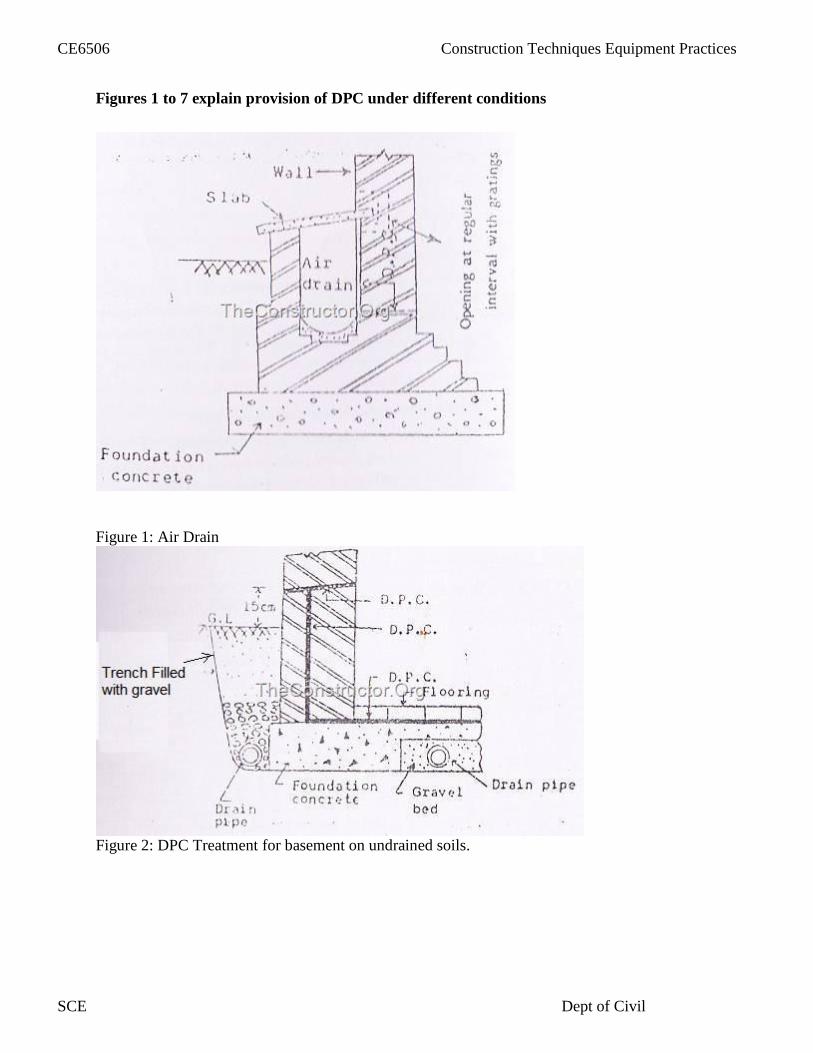
Figures 1 to 7 explain provision of DPC under different conditions
Figure 1: Air Drain
Figure 2: DPC Treatment for basement on undrained soils.
CE6506 Construction Techniques Equipment Practices
SCE Dept of Civil

Figure 3: Plan of building showing DPC
Figure 5: Asphalt tanking for basement
CE6506 Construction Techniques Equipment Practices
SCE Dept of Civil

Figure 6: DPC for flooring
2.8 FLOORS
The purpose of floor is to provide a level surface capable of supporting the occupants of thebuilding, furniture, equipment and some time interior wall
The floor must satisfy the following requirements
CE6506 Construction Techniques Equipment Practices
SCE Dept of Civil

Adequate strength and stability Adequate fire resistance Sound proof Damp resistance Thermal insulations
2.8.1 Components of a floor
Sub floor, basecourse or floor base
Floor covering or flooring
Selection of flooring materials
Factor that affect the choice of flooring
Initial cost Appearance Cleanliness Durability Damp resistance Sound insulation Thermal insulation Fire resistance Smoothness Hardness Maintenance
2.8.2 Types of flooring
Mud flooring and muram flooring Brick flooring Flag stone flooring cement concrete flooring Terrazzo flooring Mosaic flooring Tiled flooring Marble flooring timber flooring Asphalt flooring Rubber flooring Linoleum flooring Cork flooring
CE6506 Construction Techniques Equipment Practices
SCE Dept of Civil

Double are masons Glass flooring Plastic or pvc flooring
Mud flooring and muram flooring
This type of flooring is cheap, hard highly impervious
It is easy to construct and easy to maintain
It has good thermal insulation property due to which it remains cool in summer and warm inwinter
Over a well prepared ground 25 cm thick selected moist earth is spread and it rammed well tocompacted thickness of 15cm
In order to prevent cracks small quantity of chopped straw is mixed
Muram flooring
Muram is a form of disintegrated rock with binding material
To construct such a floor a 15 cm thick layer muram is laid over prepared sub grade over it 2.5cm thick powder layer of muram is spread and rammed
Brick flooring
The sub grade is compacted properly, to the desired leveland 7.5 cm thick layer is spread
Over this a course of brick is laid flat in mortar is built
Such flooring is used in cheap construction, especially where good bricks are available
Flag stone flooring
Flag stone is laminated sand stone available in 2cm to 4cm thickness in the form of stone slab of30X30 cm or 45X45cm and 60X60 cm
This type of works also called paving.The stones are laid on concrete base the subsoil is properly compacted over which 10 to of limeconcrete or lean cement concrete is laid
Cement concrete flooringThis is commonly used for residential, commercial even industrial building..
It is moderately cheap quite durable and easy to construct
CE6506 Construction Techniques Equipment Practices
SCE Dept of Civil

Double are masons
The floor consist of two components
Base concrete
Topping or wearing surface
The base course ma be 7.5 to 10 cm thick
The topping consist of 1:2:4 cement concrete
Terrazzo flooring
Terrazzo flooring is another type of floor finish that is laid in thin layer over concrete topping
It is very decorative and good wearing properties
Terrazzo is a specially prepare concrete surface containing cement and marble chips in theproportion to 1:1 1/4 to 1:2
When the surface has set the chips are exposed by grinding operation
Mosaic flooring
Mosaic flooring Is made of small pieces of broken tiles of china glazed or of cement or of marblearranged in different pattern
These pieces are cut to desired shape and sizes
a concrete base is prepare as in the case of concrete flooring over that 5to8 thick lime surkhimortar is spread over an area, over this 3mm thick cementing paste is layered and is left to dryabout 4 hours, there after small pieces of broken tiles or marble pieces of different colorsarranged definite pattern and hammered in different layers
Tiled flooring
Tiledflooring is constructed from square, hexagonal or other shapes made up of clay cementconcrete and terrazzo. These are available In various thicknessThes are commonly used in residential houses, schools, hospitals and other public buildings
Over the concrete base a 25 to 30 mm thick layr of lime mortar 1:3 to serve as a beddingThe bedding mortar is allowed to harden for 12 to 24 hours
Neat cement slurry is spread over it and the tiles are laid flat over it
Marble flooring
It is the superior type of flooring used in bathrooms and kitchens of residential building andhospitals ,sanitorium ,temples etc
After the preparation of base concrete 20 mm thick bed layer of 1:4 cement mix spread under the
CE6506 Construction Techniques Equipment Practices
SCE Dept of Civil

Double are masons
area of each individual slabs.
The marble layer is then laid over it and pressed with wooden mallet and leveled
Timber flooring
Timber flooring is used for carpentry halls ,dancing halls auditoriumEtcThese are not commonly usedin India because its costlier
But hilly area where wood is available and temperature drops very low timber flooring is quitecommon
The suspended type of wooden floor is supported above the ground
The solid type of wooden floor is fully supported on the ground
2.9 SCAFFOLDING
When te higt of wall or column or othet structural member of a building exceeding1.5 mtemporary structures needed to support trhe platforms over which the work man sit and carry othe work
These temporary structures constructed very close to the wall is in the form of imber o steelframe work commonly called as scaffoldings
Components of scaffoldings Ledgers
2.9.1 Single scaffoldings
This consists of a single frame work of standards, legers, put logs etcConstructed parallel to the wall at a distance of about 1.2 meters
The standards are placed at a distance of 2to2.5m interval
Braces Put logs Transoms Boarding Guard rail Toe board Single scaffolding or brick layer scaffolding Double scaffoldings or masons scaffoldings Cantilever or needle scaffoldings Suspended scaffoldings Trestle scaffolding Steel scaffolding Patented scaffoldings
Ledger connected with the standards, and are provided at a vertical distance of 1.2to 1.5 m
CE6506 Construction Techniques Equipment Practices
SCE Dept of Civil
Double are masons
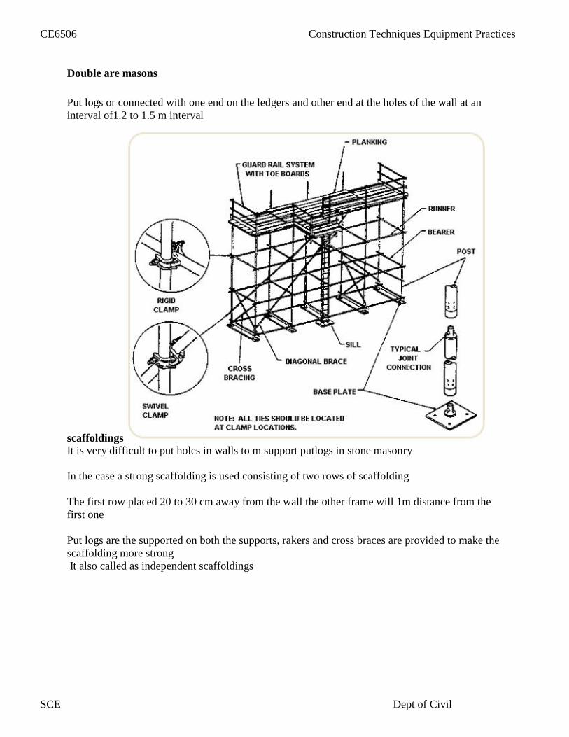
Put logs or connected with one end on the ledgers and other end at the holes of the wall at aninterval of1.2 to 1.5 m interval
scaffoldingsIt is very difficult to put holes in walls to m support putlogs in stone masonry
In the case a strong scaffolding is used consisting of two rows of scaffolding
The first row placed 20 to 30 cm away from the wall the other frame will 1m distance from thefirst one
Put logs are the supported on both the supports, rakers and cross braces are provided to make thescaffolding more strongIt also called as independent scaffoldings
CE6506 Construction Techniques Equipment Practices
SCE Dept of Civil

2.9.2Cantilever or needle scaffolding
Cantilever supports can be used under following circumctances
Ground is week to support standardsConstruction of the upper part of the wall is to be carried outIt is required to keep the ground near wall free for traffic etc i
It ha s two types
Single Frame
Te standards are supported on series of needle taken out through opening or through holes
Double frame
The needles are projecting beams are strutted inside the floors
2.9.3 Suspended scaffolding
It is the light weight scaffolding used for repair works such as pointing, painting etc
The working platforms are suspended from roofs by means of wire ropes or chains etc
CE6506 Construction Techniques Equipment Practices
SCE Dept of Civil

2.9.4 Trestle scaffolding
Such type of scaffoldings are used for painting and repairing work inside the room up to a heightof 5mThe working platform is supported over the top of movable contrivances such as tripods laddersetc
2.9.5 Steel scaffolding
Steel scaffolding is practically similar to the timber scaffolding, here wooden members arereplaced by steel couplets are fittings
Such scaffolding can be erected and dismantled rapidly
It has a greater strength and greater durability
2.9.6 Patented scaffolding
Many patented scaffolding made of steel are available in the marketThos scaffoldings are equipped with special couplings frames etc
2.10 TRUSSES
Trusses are the frame formed by number of straight members connected in the form of triangles
The embers are made by steel angles and they are joined by rivet or welding, these joints arecalled nodes
It is assumed that the external loads act at the nodes only and the members are subjected to onlytension or compression
The compression members are called as struts and the tension members are called as ties
Steel roof trusses are used under the following condition
Large spans are to be covered
Intermediate columns are to be avoided to have an unobstructed working area inside
There is a heavy rain or snow fall
CE6506 Construction Techniques Equipment Practices
SCE Dept of Civil
Types of roof trusses
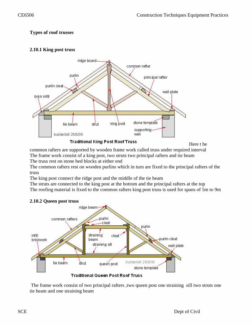
2.10.1 King post truss
Here t hecommon rafters are supported by wooden frame work called truss under required intervalThe frame work consist of a king post, two struts two principal rafters and tie beamThe truss rest on stone bed blocks at either endThe common rafters rest on wooden purlins which in turn are fixed to the principal rafters of thetrussThe king post connect the ridge post and the middle of the tie beamThe struts are connected to the king post at the bottom and the principal rafters at the topThe roofing material is fixed to the common rafters king post truss is used for spans of 5m to 9m
2.10.2 Queen post truss
The frame work consist of two principal rafters ,two queen post one straining sill two struts onetie beam and one straining beam
CE6506 Construction Techniques Equipment Practices
SCE Dept of Civil

The common matters rest on wooden purlins
The staining beam resist the horizontal thrust developed
The struts are connected to the queen post at the bottom and the principal rafters at the top
2.10.3 North light roof truss
North light or saw tooth roof truss is special type of roof trusses suitable for factories engaging inmanufacturing work
North light truss is sawtooth
Actual lighting is taken an advantage during day time by using the north light roof trussesIn this type of trusses vertical drops are provided this drops are covered with glasses so as topermit light in to the interior
2.11 Centering and shuttering
Shuttering is the temporary ancillary construction used as a mould for the structuresIn which the concrete is placed and allowed to hardened
These are classified as steel wooden plywood combined woods steel, reinforced concrete andplain concrete
Requirements of shutteringThe material should be cheap and should be suitable for re use several times
It should be practically water proof so that it should not observe water from concrete
It should be strong enough to with stand all loads coming on it
It should be stiff enough so that deflection is minimum
The surface of the formwork should smooth and it should afford easy stripping
CE6506 Construction Techniques Equipment Practices
SCE Dept of Civil

Loads on form work
Live load due to labour etcDead weight of wet concreteHydrostatic pressure of the fluid concreteImpact due t pouring concrete
Shuttering for columnComponents
Sheeting or column shutter all around the columnYokesWedgesbolt
Shuttering for beam and slab floor
The slab is continous over the beam
The slab is supported on 2.5 cm thick sheeting laid parallel to the main beam
CE6506 Construction Techniques Equipment Practices
SCE Dept of Civil

The boarding may be 4 to 5 cm thick for walls up to 3to 4m high
The boards are fixed to 5cmX10cm posts known as struts are soldiers
2.12 ROOF FINISHING
Roof finishing accessories include all types of accessory materials that are used to finish a roof.Flashing, drip edge, and roof drains are all examples of roofing accessories.
Roof finishing accessories are widely available for a range of applications and may be chosenfor functional, aesthetic, or budgetary reasons.
Roofing accessories are largely made from aluminum, steel, copper, or PVC vinyl. They includea range of products including
Rain gutters and Drains and guards
Flashing or weatherproofing materials
Roof caps
Drip edges
Ridges and shingles
Chimney caps
Leader boxes
Finials and turrets
Weathervanes.
Rain gutters and Drains and guards
Rain gutters, drains and guards are roof finishing accessories that collect and divert rainwateraway from the roof and building foundation.
These types of roof finishing accessories may also reduce erosion, prevent leaks in thefoundation or basement, reduce water exposure on painted surfaces, and collect water foradditional use.
Rain gutter, drain and guard roof finishing accessories may be available with screens, louvers, orhoods for additional protection.
Flashing or weatherproofing materials
Roof finishing accessories also include flashing, also known as weatherproofing.
Flashing refers to installing a thin, continuous piece of sheet material to prevent the passage ofwater into the structure from a joint or angle.
Flashing roof finishing accessories are commonly used around protruding objects in the roof,such as chimneys or pipes, to prevent water from reaching seams or joints.
CE6506 Construction Techniques Equipment Practices
SCE Dept of Civil

Roof caps, drip edges, ridges and shingles, and chimney caps
Roof caps, drip edges, ridges and shingles, and chimney caps are also common, functional rooffinishing accessories
. Roof caps provide ventilation via the rooftop. They are commonly made from copper orgalvanized steel, and often include an insect screen.
Drip edge roof finishing accessories are useful in stopping water from seeping under a roofdeck, which can prevent frame rot.
Roof ridge caps and shingles are also used as finishing accessories. Roof shingles are individual,overlapping elements used for water-resistance.
At the roof ridge, there is typically a copper, lead, or plastic cap to ensure water protection.
Ridge vents are also commonly used as roof finishing accessories to provide ventilation to atticor upper crawlspaces.
Leader boxes, Finials and turrets and Weathervanes.
Finishing accessories can also be decorative.
These accessories include leader boxes, finials and turrets, and weathervanes. Leader boxaccessories are used with gutter systems to hide or diminish the sight of leader elbows, and areavailable in a range of decorative styles, shapes, and designs.
Roof finials and turrets are caps or towers affixed to the highest point of the roof, largelyfor decoration. Turrets are often designed to hold clocks or bells.
Similarly, weathervanes are another type of roof finishing accessory often used for decorationat the highest point of the roof. Weathervanes are not solely used for decoration, however, asthey also point to the direction of the wind. Other, unlisted types of roof finishing accessoriesmay also be available.
2.12.1 ACOUSTICS
Acoustics is the science of sound ,which deals with origin ,propagation and auditory sensationof sound and also with design and construction of different building units to set optimumcondition for producing and listenig speech musi etc
2.13 FIRE PROTECION
No building material is perfectly fire proof
A wider interpretation of the fire safety may be deemed to cover the following aspectsFire prevention and reduction of number of out breaks offire
Spread of fire both internally andexternally
CE6506 Construction Techniques Equipment Practices
SCE Dept of Civil
Safe existence of any and all occupants in the event of an out breaks offire
Fire load
Fire load is the amount of heat in kilocalories which is liberated per square meter of floor areaof any combustible parts of the building itselfThe fire load is determined by multiplying the weight of all combustible materials bytheir calorific value and dividing the floor area under consideration
Grading of building according to fireresistanceThe national building code of India (sp:7-1970) divides building in to the following fourtypes
according to the fire load the building is designed to resist
Type 1 construction all structural components have 4 hours fire resistance
Type 2 construction all structural components have 3 fire resistance
Type 3construction all structural components have 2 hours fire resistance
Type 4 construction all structural components have 1 hour fire resistance
General fire safety requirements for buildings
All building and particularly building having more than one storey shall be provided withliberally designed and safe fire proof existence
The exist shall be so placed that they are always immediately accessible and each is capable oftaking all the persons on that floor a s alternative escape route
Escape route shall be well ventilated as persons using the escapes are likely to over come fromsmoke
Fire proof door shall conform rigidly to the fire safety requirements
Electrical and mechanical lifts while reliable undr normal condition may not always be relied onescape purpose
Lift shafts and stairways invariably serve as flues are tunnels thus increasing the fire byincreased draught
Floors are required to withstand the effect of fire for full period stated for the particular grading
Roofs of the various fire grades of the building shall be designed and constructed to withstandthe effect of fire for the maximum period
CE6506 Construction Techniques Equipment Practices
SCE Dept of Civil

UNIT III
SUB STRUCTURE CONSTRUCTION
3.1 Types of structures under jacking
Box jacking
Arch jacking
Pipe jacking
OPERATONSThe box shaped tunnel structures are pre fabricated units which are pushed into soil by hydraulicjack
Soil is excavated at the advancing face by manual means or by excavatorsTo avoid settlements of over laying roads or rail track soil is excavated after it enters the cuttingheads
Excavation ahead of the cutting is avoided the cutting head is moved forward in smallincrements to avoid any having of the road or rail track
In addition to that, without stabilizing the soil, the box technique would cause the super structureto settle the threatening structure failure so the ground ahead of tunnel boxes needed to be frozen
3.2 PIPE JACKINGIn tunnels of damages above 2m men and machines worked the tunnel phase exacting andproviding soil support to the excavator soil by erecting the lining. The tunnel diameter becomessmall it becomes difficult for workers to carry out soil excavation of in erect the tunnel liningsystem with in the tunnel shield
For diameter in the range of 0.5m to 1.5m it is more efficient to excavate the soil by drillingsystems controlled from a shaft or a pit to push the tunnel lining segment from the shaft or pitthese techniques are often referred to us pipe jacking or micro tunneling techniques andequipments
Pipe jacking refers to a technique in which a man in a sitting or crouch position, user’s epic andshovels to excavate tunnel face and the pipe is jacked forward from a shaft using hydraulicjacking system
Horizontal auguring refers to a similar technique in which the man is replaced by a horizontalcontinuous flight helical auger
INSTALATIONThe pipe sections are moved forward by hydraulic jacking and the miniature TBM derive itsreaction from these sectionPipe segments of length 1 to 3 diameters 0.5 to 2m can be jacked into the soil using reactionfrom the concrete wall erected at the rior of jacking pit.
CE6506 Construction Techniques Equipment Practices
SCE Dept of Civil

In structural engineering, a diaphragm is a structural system used to transfer lateral loads toshear walls or frames primarily through in-plane shear stress
. These lateral loads are usually wind and earthquake loads, but other lateral loads such as lateralearth pressure or hydrostatic pressure can also be resisted by diaphragm action.
The diaphragm of a structure often does double duty as the floor system or roof system in abuilding or the deck of abridge, which simultaneously supports gravity loads.
Diaphragms are usually constructed of plywood or oriented stand board in timber construction;
Metal deck or composite metal deck in steel construction; or concrete slab in concreteconstruction.
The two primary types of diaphragm are flexible and rigid. Flexible diaphragms resist lateralforces depending on the tributary area, irrespective of the flexibility of the members that they aretransferring force to. On the other hand, rigid diaphragms transfer load to frames or shear wallsdepending on their flexibility and their location in the structure.
Parts of a diaphragm include:
the membrane, used as a shear panel to carry in-plane shear the drag strut member, used to transfer the load to the shear walls or frames The chord, used to resist the tension and compression forces that develop in the
diaphragm, since the membrane is usually incapable of handling these loads alone.
3.4 TUNNELING
Process of making tunnels in order to reduce distance of travel or traffic congestion for highwayand railway is called tunneling
Tunneling is important for the following purpose
o Time saving and reduction in fuel oAvoid unwanted traffic congestion oMaintain a proper speedo Avoid tiredness of travelo Avoid unwanted accidentso To avoid deforestation and death of animal while crossingo To avoid land slide in hilly regiono To avoid the long route around the mountaino To reduce the length of highway and railway and it may be economicalo To have flatter gradient that is essential to maintain the speed of the vehicle
Tunneling types depending upon the shapes
Poly centric
Horse shoe
3.3 DIAPHRAGM WALL
CE6506 Construction Techniques Equipment Practices
SCE Dept of Civil

Size of the tunnel
It depends upon the number of track and the width and length of the mountain
Alignment of tunneling
o Identify the shortest routeo Height of mountain should be lesso Mark the points on the mountaino Transfer the tunnel inside the mountain by making of required deptho Checking the tunnel cross section whether equal every where
Methods of tunneling
Shaft tunneling
Pilot tunneling
Shaft tunnels
Vertical passages are created along the line o the tunnel then the tunnels can be excavated by thepassage of having distance half of the distance between adjacent passage openings are availableto take the excavated material ,shafts can also be used to pump out the water
Pilot tunneling
If the height of the mountain is more then we can exercise this method of tunneling but uf hehorizontal length is more, shaft tunneling is done
3.5 PILE DRIVING
This is the process of inserting the pile inside the soil
It is a process by way of which a pile is forced in to the ground with out excavating the soil
Pile driving an be done by two methods
Using hammering
Using pile driver
Hammering
Heavy bl0w is given by means of a hammer
Variety of hammers available to perform some of the acion
Drop hammer Single acting hammer Double acting hammer
CE6506 Construction Techniques Equipment Practices
SCE Dept of Civil

Diesel hammer and Vibrating hammer
Drop hammer
The hammer is lifted by a winch and dropped down
The hammer is connected to the rope by a hook
When it is lifted up after reaching a particular height it is dropped down
Single acting hammer
Hammer is lifted by stream and dropped then it will fell down in the top of the pile bygravitational force
Double acting hammer
It is the same as that of single acting but here both the lifting and dropping is done by steamengine
Diesel hammer
The process of lifting and dropping is done by diesel engine
Vibrators
If the soil condition is loose ,then using some vibrators the pile is inserted
3.6 SHEET PILES
It is the type of pile that is made of concrete, steel or wood
The thickness of the pile is very less when compared to the length and width of the pile
To prevent the entry water in construction the sheet piles are used, this is also used to separatethe vertical member of the building
The piles are inserted by some machine the depth of the piles can be increased by proper joints insuccessive installment
Functions
To enclose the site or part to prevent escape of loose soil
To retain the sides of trenches or excavation
To construct retaining wall in the marine structures
To prevent seepage below the dams or hydraulic structures to construct coastal defense work
To protect the foundation from scouring action of nearby river
CE6506 Construction Techniques Equipment Practices
SCE Dept of Civil

Concrete sheet piles
Reinforced precast unit having the width of 50 to 60 cm and thickness 2to 6cm and the depth canbe increased by further installment
Timber sheet piles
it is used only for temporary works ,the width of the pile varies from 225to 280 cm the thicknessshall not be less than 50mm
3.7 DEWATERING
DEFINITIONWhen water table exists at a shallow depth below ground surface, it is essential to lower thewater so as to carry out construction of foundation, basement, and metro tunnels etc.This isachieved by pumping out water from multiple wells installed at the site. The process is called asdewatering.
Types of dewatering method
Dewatering can be done by adopting one of the following four strategiesDewatering of soil by temporary lowering of water table using wells and pumps prior excavationas depleted in figure
Allowing water to reap into excavation area, collecting it in sumps and pumping it out. Beforethat adequate steps have to be taken to support the soil on sides of the excavated area, to preventwashing away of fines and have sufficient space for the work area.
Making the soil around excavated zone impermeable by technique such as grouting are freezingso that inflow of water is stop are minimized.
INSTALATION TECHNIQUE
Sufficient size and capacity of dewatering system is necessary to lower and maintain groundwater table and to allow material to be excavated in a reasonable dry condition.Excavation slopes to be stabilized where sheeting is not required
Dewatering system is to be operated continuously until backfill work has been completed.
CE6506 Construction Techniques Equipment Practices
SCE Dept of Civil

When construction operation have to be excited below the ground water table level. Dewateringof soil can be done by the following methods
Collecting water in sumps and pumping it out.
Installing well points small or deep wells and pumping out ground water
Using special technique in fine grained soils such as vaccum dewatering and electro-osmosis
WELL POINTSTo pump out the ground water small sized wells called well points are used for a more dryworking area the two methods used most often for lowering water table below the excavationlevel are the well point method and the deep well method.
WELL POINT METHOD:This is economical and useful for lowering the water table by 15m or less.Incase of well point method or deep well method it is based on the fact that removal of water bycontinuous pumping from a well causes the water table level to become depressed and result inthe formation of draw down.
When a series of wells are placed close to each other, the overall effect is lowering of the watertable level.
Well points, being smaller, are easy to install.Well points, can lower the water table by only 6.7m because the pump, is located at the ground
surface and connected to group of well points through a pipe, cannot lift water from greaterdepth.Beyond 7m, multistage well points are used.
DEEP WELL METHOD
This method is useful for lowering the water table by more than 15m.
Deep wells have larger diameter more depth and greater spacing.
The pump is located at the bottom of well and hence can pump out water from greater depth.
Deep wells become more economical if more points are required.
3.7.1DEWATERING WELLPOINTS
CE6506 Construction Techniques Equipment Practices
SCE Dept of Civil
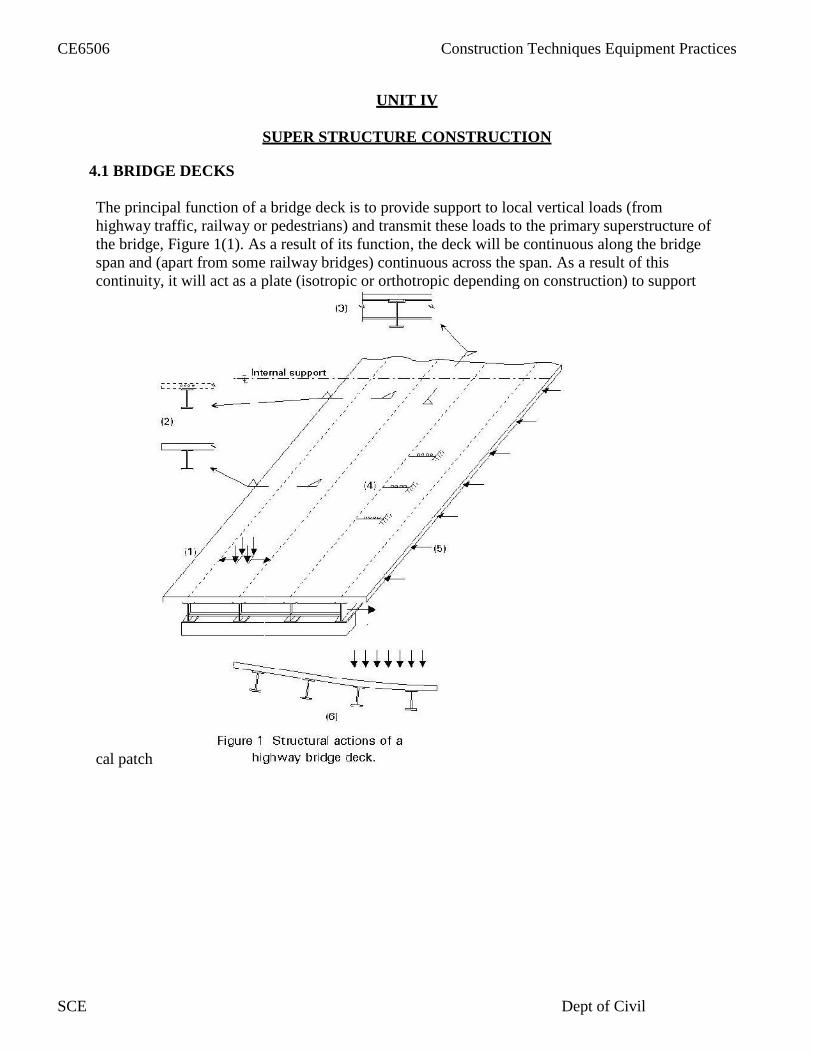
UNIT IV
SUPER STRUCTURE CONSTRUCTION
4.1 BRIDGE DECKS
The principal function of a bridge deck is to provide support to local vertical loads (fromhighway traffic, railway or pedestrians) and transmit these loads to the primary superstructure ofthe bridge, Figure 1(1). As a result of its function, the deck will be continuous along the bridgespan and (apart from some railway bridges) continuous across the span. As a result of thiscontinuity, it will act as a plate (isotropic or orthotropic depending on construction) to support
cal patch
CE6506 Construction Techniques Equipment Practices
SCE Dept of Civil

Continuity ensures that whether or not it has been designed to do so, it will participatein the overall structural action of the superstructure.
The overall structural actions may include:
Contributing to the top flange of the longitudinal girders, Figure 1(2). Contributing to the top flange of cross girders at supports and, where present
in twin girder and cross girder structures, throughout the span, Figure 1(3). Stabilising longitudinal and cross girders, Figure 1(4). Acting as a diaphragm to transmit horizontal loads to supports, Figure 1(5). Providing a means of distribution of vertical load between longitudinal girders,Figure 1(6).
It may be necessary to take account of these combined actions when verifying the designof the deck. This is most likely to be the case when there are significant stresses from theoverall structural actions in the same direction as the maximum bending moments fromlocal deck actions, e.g. in structures with cross girders where the direction of maximummoment is along the bridge.
The passage of each wheel load causes a complete cycle of local bending stresses. Thenumber of significant stress cycles is, therefore, very much higher for the deck than forthe remainder of the superstructure. In addition, some of the actions of the deck arisingfrom its participation in the overall behaviour are subject to full reversal;
an example is the transverse distribution of vertical load between girders. For both thesereasons, fatigue is more likely to govern the design of the bridge deck than the remainderof the superstructure.
4.2 SHELL STRUCTURES
Shells are 3d structures constructed on storage tanks or roof for large column area such asindoor stadiums, exhibition halls, theatres, complex churches etc
ClassificationSingly curved Doubl curved Cylindrical shells Singly curvedIt can be used for rectangular shape buildings, shells represents the roof of the building
Dome storage tank for water and petroleum is example for single curved
Doubly curved
For doubly curved structures the super structure should be in hexagonal or circular shape
Cylindrical shape
These ae just modification of pitched roof and frequently emloyed in modern ageconstruction
It has two types
CE6506 Construction Techniques Equipment Practices
SCE Dept of Civil

North light shell roof
Barell vault shell roof
Both are different to provide lighting effect in factories
In barell vault ventilation s provided in middle
4.3 Off shore platforms
Off shore platforms are self contained platforms with adequate facilities for drilling,derrick, drilling mud electric power, pumping equipment for the offshore construction theseare artificial facilities above the elevation of off shore platforms
Off shore platforms can be classified as
Fixed Off shore platforms
Bottom supported structuresCompliant platforms and floating platforms
Construction principles of offshore platformsSelection of operational criteria
Selection of environment
Environmental factors
like Storming wind
velocity Storming
wave height
Tidal conditionsBefore analysis and design of foundation it is necessary to determine the soil characters ofthe sea shore. Capacities of the available crains will influence the operational activities ofplatform constructions.
The fixed platforms can be classified intoJacket or template structuresGravity structures
4.4 ERECTING LIGHT WEIGHT COMPONENTS ON TALL STRUCTURES
Besides high raise buildings the usage of steel element is also popular withconstruction of hospital and commercial complexes
Instead of concrete beams and columns more than 6100 tonnes of steel have been used tobuild the main frames
CE6506 Construction Techniques Equipment Practices
SCE Dept of Civil
Light weight blocks are used for patricians to reduce the dead load building
The usage of permanent concrete form works and structural steel elements will be themain constituter for erecting light weight components on tall structures results rapidspeed of constructions.
Hence the erection of steel beams and columns as well as the installation of concrete formwork consumes only less time
Self drilling tapping screws are the most prevalent fasteners. Steel to steel connectionscan be carried out to connect struts or joist and track together
Entire can be erected manually with out the use of heavy equipment
All these structures require few battery powered screw gunes and some ropes and pulleys
No scaffoldings is require for assembly and disc assembly of the structures because thestructure itself provides the scaffoldings as it goes up or comes downAlmost any number of column sections can be added to make it any height we desire
During the construction of tall structures the following equipments areused for theaerial transporting and handling
CE6506 Construction Techniques Equipment Practices
SCE Dept of Civil
UNIT V
CONSTRUCTION EQUIPMENT
5.1 Introduction to construction equipments
Types of earth moving equipment
Classified into following types
Production equipment Equipment used for digging and moving Service equipment Dozers and motor girders
5.1.1 Tractors
Tractors are machine which change the engine energy into tractive energyThese are primarily used for pull or push the loads
They are also used for different purposes by mounting many types of accessories
Types of tractor
Crawler type or track typeRubber tired or wheel type
The tractor is multi purpose machine
Light models are used for agricultural or short haulage worksHeavy models are employed in earth moving works, cranes, shovels or special rigs
Wheeled types or employed in light but speedy jobs
Main constituents of tractor are engine ,clutch ,transmissonsystem,ground drive andcontrols
Factors should be considered while selecting a tractor dozer
Size of the dozer for given job the type expected from the track to dozer
The type and condition of haulroad distance to be move
5.1.2 BulldozersDozers are machine designed primarily for cutting and pushing the material over shortdistance
They consist with a front mounted blade controlled by hydraulic cylinder to vary the depth
CE6506 Construction Techniques Equipment Practices
SCE Dept of Civil
of cut and rate of leveling depending on the material and application
a dozer is frame mounted unit with a blade, curved in its section, extending in front ofthe tractor
Bulldozer is most versatile and most important equipment on construction project
Basically its pushing unit but its widely used as multipurpose equipment and canperform large number of operations with minor changes
5.1.3 Scrapers
Scrapers are the devices to scrap the ground and load it simultaneously, transport it forthe required distance and dump it and then spread it for the required area
The scrapers are designed to dig,load,haul,dump and spread
The scrapers are of three types
towed type conventional type self loading or elevating scrapers
Towed type
The towed type scrapers are provided with either cable or hydraulic controlIt can be operated in extremely adverse conditionConventional scrapers
These are generally manufactured from 10to 25cubicmetres
Self loading scrapers
These are twin engine scrapersIt can work completely independently of all other plants
It has the following parts
o Bowlo Cutting edgeo Aprono Tail gate or ejector
Following or three major operations of scrapers
Loading or diggingTransportingUnloading
CE6506 Construction Techniques Equipment Practices
SCE Dept of Civil

5.2 SELECTION OF EQUIPMENT
Proper selection of construction equipment place a vital role in the speedy and economicalcompletion of the construction
Following are the main points which should be considered while selection off theconstruction equipments
Suitable for job conditionThe equipment must meet the requirement of the work climate and working condition
Size of the equipmentSize of the equipment it should be such that must be able to be used with other equipments
If the equipment selected for larger size it will remain idle inmost of the time
Standardization
It is better to have same type and size of equipment in a construction then it is easy to havespare parts, and to understand its operations
Availability ofequipment
Availability of spareparts
Multi purpose equipments the selected equipments must be capable of performingvarious operations
Availability of know how
The equipments selected should be satisfactorily handled by the available operatorsand machine
Use in future projects The economical aspects Reliability of the equipments Service
support
Operating requirements
Past performance
Reputation of the manufacturer
Warranty and guaranty offered by the manufacturer
Adequacy of drive mechanism
CE6506 Construction Techniques Equipment Practices
SCE Dept of Civil

5.3 EXCAVATORS
Excavators are basically digging machines having three major components
An under carriage to give mobility
A super structure with operators cabin mounted on either a sloe ring to traverse through360◦or on a rigid frame
Hydraulically articulated boom or tipper arms with bucket
Types of excavatorsCrawler mounted excavatorsTruck mounted excavators
Self propelled excavators
Excavators mounted on barge or rail
Compactors
Compaction is the process where by material particles are constrained to pack more closelytogether through
a reduction of air void content generally by mechanical means
Types of compactors
static smooth wheeled rollers sheep foot and pad foot rollers pneumatic tired rollers vibratory rollers
Static compaction equipment
It has several types
towed static smooth compactors static sheep foot or pad foot compactors
static three wheel self propelled compactors static tandem compactors three axle static compactors
Towed static smooth compactors
Smooth rolls where the first type of rolling compaction equipment used
CE6506 Construction Techniques Equipment Practices
SCE Dept of Civil

These where pulled by men or horses and were first used by Romans to smoothen thereroads
Static sheep foot or pad foot compactors
When compacting the earth the feet penetrate deep in to th e loose material during the firstpasses and compact the soil from bottom up
The kneading effect of sheep foot compactors is used to break up theEarth lumps and reduce the air voids
Static three wheeled self propelled compactors
These have three rolls a small usually split steering role in the front
Two large drive rolls mounted on rear axle at both the end
Static tandem compactors
Tandem rolls have two equal sized rolls and are centered in line tandem
These are used for the compaction of bituminous layer as they leave a smooth surface
Vibratory compaction equipments
It can be divided in to following types
Tandem vibratory compactors Towed vibratory compactors Towed sheep foot and tamping foot vibratory compactors Self propelled vibratory compactors Hand guided vibratory compactors
5.4 Equipment for concrete mixing
Concrete mixersFor small jobs conc. mixers are used to mix the ingredients of the concreteFollowing type of concrete mixers are used in the construction
Hand felt tilting drum mixersThese are smaller capacity mixers ,aggregate cement and water fed in to the drum by hand
Loader fed tilting drum mixers
These are larger capacity as compared to hand fed mixers
These are fixed with the loading hopper operating by the wired rope for loading
CE6506 Construction Techniques Equipment Practices
SCE Dept of Civil

Reversing drum mixers
This type of mixer is used on comparatively larger works
The mixer drum is horizontal and it is non tilting type
It has blades which work alternatively
Roller pan mixersThese mixers are primarily used for mortars ,the rollers and mixer blades rotate in a pan andnot only mixing material but also kneading and crushing it
5.5 Tunneling equipment
Selection of equipment
Selection of equipment for tunneling depends upon quantum of work involved
So that the tunneling work is carried out economically,speedly and safely
Muck loading
Mucking is the operation of loading the broken rock or earth for removal from tunnelMucking process can be done by the following equipments
Power shovels Tractor
loader Mucking
machines
Tunnel boring machines
Tunneling is mostly done by conventional and drilling and blasting methods
Working principle of tunneling these machines perform the bring operation through the rotationof the front head against the rock face
The mole has circular cutter head in the front provided with fixed cutters of desired shapesThe cutter head while rotating is pressed against the rock to cut or pulverize it
The tunnel boring machines are two types
Single stage machine
These are recommended for small dia tunnels of 3 to 6 m
These machine are allowed to access change in bore hole diameter and this can be done withoutany change of machines
CE6506 Construction Techniques Equipment Practices
SCE Dept of Civil

A Course Material on
By
DEPARTMENT OF CIVIL ENGINEERING
SASURIE COLLEGE OF ENGINEERING
VIJAYAMANGALAM – 638 056
Assistant Professor
Mr. P. JAGATEESH
CONSTRUCTION TECHNIQUES, EQUIPMENT AND PRACTICES

QUALITY CERTIFICATE
This is to certify that the e-course material
being prepared by me and it meets the knowledge requirement of the university curriculum.
Signature of the Author
Signature of HD
Name: N.Sathish Kumar
SEAL
Designation: Assistant Professor
Class : IV Year CIVIL
Name: P.JAGATEESH
This is to certify that the course material being prepared by Mr. P.JAGATEESH is of adequate
quality. He has referred more than five books amount them minimum one is from aborad
author.
Subject Code : CE2404
Scubject : CONSTRUCTION TECHNIQUES, EQUIPMENTS AND PRACTICES

h h h h h[ T y pe here] [Ty pe here] [Ty pe here ]
Consruction Techniques, EquipmentAnd Practice
UNIT I - CONCRETE TECHNOLOGY
PART-A
1) What are all the types of cement?
o Ordinary Portland cement
o OPC33,OPC43 and OPC53 grade
o Rapid hardening cement
o Extra rapid hardening cement
o Sulphate resisting cement
o Portland slag cement
o Quick setting cement
o Low heat cement
o Portland pazzolona cement
o Air entraining cement
o Colored cement
2) Differentiate dry process and wet process of manufacturing cement?
Process
Lime stone and clay are ground to fine powder separately and are mixed together Water is added to make a thick paste which contains 14% of moisture The paste format are dried and off charged into a rotary kiln The product obtained often calcinations in rotary kiln
Process
o The crushed raw materials are fed in to a ball mill and a little water is addedo The steel balls in the ball mill pulverized the raw material which form a slurry with
watero The slurry is passed through storage tanks where the proportioning of compound is
adjusted to ensure desired chemical composition
P.JAGATEESH 1 2015-2016
Construction Techniques, Equipments and Practices IV Year/ VII Semester CIVIL ENGINEERING

h h h h h[ T y pe here] [Ty pe here ][Ty pe here ]
3) Define batching, what are all the methods of batching?
The measurement of materials for making concrete is known as batching.Methods of batching
Volume batchingWeigh batching
4) What are all the raw materials of the cement?
o Limeo Silicao Aluminao Calcium sulphateo Iron oxideo Magnesium oxideo Sulphar ti oxideo alkalis
5) Write notes on steam curing.
This approach is widely used in precast concrete units.here the precast units are kept underwarm and damp atmosphere of a steam chamber.
6) Define non destructive testing.Non destructive testing is done on haredend concrete in non destructive testing methods soe
properties of concrete are used to estimate strength durability ,elastic parameters,crack depth microcracks and progressive deteriotion of concrete.
7) What are all the types of concrete test?Slump testcompressive testsplit tensile strength
P.JAGATEESH 2 2015-2016
Construction Techniques, Equipments and Practices IV Year/ VII Semester CIVIL ENGINEERING

h h h h h[ T y pe here] [Ty pe here ][Ty pe here ]
PART-B
1) Explain the manufacturing of cement with neat sketches and flow chart
Raw materials used
CalcareousArgillaceous
Calcareous materials used areCement rockLime stoneMarlChalkMarine shell
Argillaceous materials used areClayshaleslateblast furnace slag
Process manufacturing cementDry processWet process
Dry process
General
Adopted when the raw materials are quite
hard The process is slow an the product is
costly Process
Lime stone and clay are ground to fine powder separately and are mixed togetherWater isadded to make a thick paste which contains 14% of moisture
The paste format are dried and off charged into a rotary kiln
The product obtained often calcinations in rotary kiln
The clinker I obtained as a result of incipient fusion and sintering at a temp about 1400◦cto1500◦ c
The clinker is cooled to preserve the meta stable compounds and there solid
solutions Dispersion of one solid with another solid which made the clinker again
P.JAGATEESH 3 2015-2016
Construction Techniques, Equipments and Practices IV Year/ VII Semester CIVIL ENGINEERING

h h h h h[ T y pe here] [Ty pe here ][Ty pe here ]
heated Clinker is again cooled and grounded in tube mills where 2-3% gypsum is
added
The purpose of adding gypsum is to coat the cement particle by interfering the processof hydration of cement particles
Wet process
The operations are
Mixing Burning Grinding
Process
The crushed raw materials are fed in to a ball mill and a little water is added
The steel balls in the ball mill pulverized the raw material which form a slurry with water
The slurry is passed through storage tanks where the proportioning of compound isadjusted to ensure desired chemical composition
The corrected slurry having moisture about 40%,is then fed into rotary kilnWhere it loses moisture and form on to lumps
These are finally burned at 1500◦ to 1600 ◦cIt becomes clinker at this stage, the clinker iscooled and then grounded in tube mills
While grinding the clinker 3% gypsum I added this is stored in silos and packed
P.JAGATEESH 4 2015-2016
Construction Techniques, Equipments and Practices IV Year/ VII Semester CIVIL ENGINEERING

h h h h h[ T y pe here] [Ty pe here ][Ty pe here ]
2) Explain briefly about the chemicals used in concrete and their advantages
Water-reducing admixture / Plasticizers:
These admixtures are used for following purposes:
1. To achieve a higher strength by decreasing the water cement ratio at the same workabilityas an admixture free mix.
2. To achieve the same workability by decreasing the cement content so as to reduce theheat of hydration in mass concrete.
3. To increase the workability so as to ease placing in accessible locations4. Water reduction more than 5% but less than 12%
Actions involved:
1. Dispersion:
Surface active agents alter the physic chemical forces at the interface. They are adsorbed on thecement particles, giving them a negative charge which leads to repulsion between the particles.Electrostatic forces are developed causing disintegration and the free water become available forworkability.
2. Lubrication:
As these agents are organic by nature, thus they lubricate the mix reducing the friction andincreasing the workability.
3. Retardation:
A thin layer is formed over the cement particles protecting them from hydration and increasingthe setting time. Most normal plasticizers give some retardation, 30–90 minutes
Super Plasticizers:
o These are more recent and more effective type of water reducing admixturesalso known as high range water reducer
o The commonly used Super Plasticizers are as follows:
Sulphonated melamine formaldehyde condensates (SMF) Give 16–25%+ water reduction. SMF gives little or no retardation, which makes them very
effective at low temperatures or where early strength is most critical.
However, at higher temperatures, they lose workability relatively quickly. SMF generallygive a good finish and are colorless, giving no staining in white concrete.
They are therefore often used where appearance is important.
P.JAGATEESH 5 2015-2016
Construction Techniques, Equipments and Practices IV Year/ VII Semester CIVIL ENGINEERING

h h h h h[ T y pe here] [Ty pe here] [Ty pe here ]
Sulphonated naphthalene formaldehyde condensates (SNF)
Typically give 16–25%+ water reduction. They tend to increase the entrapment oflarger, unstable air bubbles. This can improve cohesion but may lead to moresurface defects.
Retardation is more than with SMF but will still not normally exceed 90 minutes. SNF is avery cost-effective.
Polycarboxylate ether super plasticizers (PCE)
Typically give 20–35%+ water reduction. They are relatively expensive per liter butare very powerful so a lower dose (or more dilute solution) is normally used.
In general the dosage levels are usually higher than with conventional water reducers,and the possible undesirable side effects are reduced because they do not markedlylower the surface tension of the water.
Accelerators:
An admixture which, when added to concrete, mortar, or grout, increases the rate ofhydration of hydraulic cement, shortens the time of set in concrete, or increases the rate ofhardening or strength development.
Accelerating admixtures can be divided into groups based on their performance andapplication:
1. Set Accelerating Admixtures,
Reduce the time for the mix to change from the plastic to the hardened state.
Set accelerators have relatively limited use, mainly to produce an early set.
2. Hardening Accelerators,
Which increase the strength at 24 hours by at least 120% at 20ºC and at 5ºC by at least130% at
48 hours. Hardening accelerators find use where early stripping of shuttering or very earlyaccess to pavements is required.They are often used in combination with a high rangewater reducer, especially in cold conditions.
Set Retarders:
The function of retarder is to delay or extend the setting time of cement paste in concrete.These are helpful for concrete that has to be transported to long distance, and helpful inplacing the concrete at high temperatures.
When water is first added to cement there is a rapid initial hydration reaction, after whichthere is little formation of further hydrates for typically 2–3 hours.
P.JAGATEESH 6 2015-2016
Construction Techniques, Equipments and Practices IV Year/ VII Semester CIVIL ENGINEERING
h h h h h[ T y pe here] [Ty pe here] [Ty pe here ]
The exact time depends mainly on the cement type and the temperature. This is called thedormant period when the concrete is plastic and can be placed.
At the end of the dormant period, the hydration rate increases and a lot of calcium silicatehydrate and calcium hydroxide is formed relatively quickly. This corresponds to thesetting time of the concrete.
Retarding admixtures delay the end of the dormant period and the start of setting andhardening. This is useful when used with plasticizers to give workability retention. Usedon their own, retarders allow later vibration of the concrete to prevent the formation ofcold joints between layers of concrete placed with a significant delay between them.
The mechanism of set retards is based on absorption. The large admixture anions andmolecules are absorbed on the surface of cement particles, which hinders further reactionsbetween cement and water i.e. retards setting.
Air Entrained Admixtures:
An addition for hydraulic cement or an admixture for concrete or mortar which causesair, usually in small quantity, to be incorporated in the form of minute bubbles in theconcrete or mortar during mixing, usually to increase its workability and frostresistance.
Air-entraining admixtures are surfactants that change the surface tension of the water.Traditionally, they were based on fatty acid salts or vinsol resin but these have largelybeen replaced by synthetic surfactants or blends of surfactants to give improvedstability and void characteristics to the entrained air.
Air entrainment is used to produce a number of effects in both the plastic and thehardened concrete. These include:
• Resistance to freeze–thaw action in the hardened concrete.
• Increased cohesion, reducing the tendency to bleed and segregation in the plasticconcrete.
• Compaction of low workability mixes including semi-dry concrete.
• Stability of extruded concrete.
P.JAGATEESH 7 2015-2016
Construction Techniques, Equipments and Practices IV Year/ VII Semester CIVIL ENGINEERING

h h h h h[ T y pe here] [Ty pe here] [Ty pe here ]
3) Explain the procedure of compression test on concrete
The compression test shows the compressive strength of hardened concrete.
The compression test shows the best possible strength concrete can reach in perfect
conditions. The compression test measures concrete strength in the hardened state. Testing
should always be done carefully. Wrong test results can be costly.The testing is done in a
laboratory off-site. The only work done on-site is to make a concrete cylinder for the
compression test.
The strength is measured in Megapascals (MPa) and is commonly specified as acharacteristic strength of concrete measured at 28 days after mixing.
The compressive strength is a measure of the concrete’s ability to resist loads which tend tocrush it.
Apparatus for compression test
Cylinders (100 mm diameter x 200 mm high or 150 mm diameter x 300 mm high) (The smallcylinders are normally used for most testing due to their lighter weight)
1. Small scoop2. Bullet-nosed rod (600 mm x 16 mm)3. Steel float4. Steel plate
Procedure for compression test of concrete
Clean the cylinder mould and coat the inside lightly with form oil, then place on aclean, level and firm surface, ie the steel plate. Collect a sample.
Fill 1/2 the volume of the mould with concrete then compact by rodding 25 times.Cylinders may also be compacted by vibrating using a vibrating table.
Fill the cone to overflowing and rod 25 times into the top of the first layer, then top upthe mould till overflowing.
Level off the top with the steel float and clean any concrete from around the mould.
Cap, clearly tag the cylinder and put it in a cool dry place to set for at least 24 hours.
After the mould is removed the cylinder is sent to the laboratory where it is curedand crushed to test compressive strength
P.JAGATEESH 8 2015-2016
Construction Techniques, Equipments and Practices IV Year/ VII Semester CIVIL ENGINEERING

UNIT-II
CONSTRUCTION PRACTICES
PART A
1. What are the general specifications for first class building?Foundation and plinth.superstructure.damp-proof course.lintels.roofing.plastering.doors and windows.distempering and colour wasting.painting.
2. What are monolithic wall? write its classifications?Monolithic walls:-Walls built of a material requiring some kind of
shuttering in the initial stages.Masonry can be classified into the following types
stone masonry.brick masonry.hollow block concrete masonry.reinforced masonry.composite masonry.
3. Define plinth.Plinth:- It is the horizontal course of stone or brick provided at the base of thewall above ground level. It indicates the height of the ground floor level above thenatural ground level. It protects the building from dampness.
4. What are classifications of stone masonryThere are two types ,they are
rubber masonry.ashlar masonry.
5. What is rubber masonry and ashlar masonry?Rubber masonry:-
Stones of irregular sizes are used. stones may be undressed or roughlydressed. using hammer having wider joints.Ashlar masonry:-
This is a costlier, high grade and superior quality of masonry. The workbuilt from accurately dressed stones with uniform and very fine joints of about3mm. thickness is termed as ashlar masonry.
P.JAGATEESH 9 2015-2016
Construction Techniques, Equipments and Practices IV Year/ VII Semester CIVIL ENGINEERING
6. Compare English bond and Double Flemish bond.English bond double Flemish bond.
More compact and stronger for wallshaving thickness more than 1(1/2)bricks.
Not pleasing appearance of the facing.No strict supervision and skill required
for its construction.More in cost than Double Flemish
bond.
Less compact and stronger.
Better appearance in the facing.Good workmanship and careful
supervision is required.Cheaper in cost-because number of
bricks bats are used.
7. What are the defects in brick masonry.Defects in brick masonry:-
Sulphate attack.Crystallization of salts from bricks.Corrosion of embedded iron or steel.Shrinkage on drying.
8. Mention the common sizes of building blocks.The common sizes of building blocks are
390x190x300 mm- standard size hollow block.390x190x200 mm- hollow building tiles.390x190x100 mm- hollow concrete blocks for partition.
9. What the types of flooring commonly used.mud flooringmuram flooringcement concrete flooringmosaic flooringtiled flooringmarble flooring
10. Define damp proof course., what are its causes of dampness.Definition :-The courses which are laid to check the entry of water or moistureinto the building are called damp proof courses.
Causes:-faulty design of structurefaulty construction or poor workmanshipuse of poor quality materials in construction.
11. Define roofs.Roof:-A roof is defined as the uppermost part of the building which isconstructed in the form of a frame work to give protection to the buildingagainst rain , heat wind etc..
P.JAGATEESH 10 2015-2016
Construction Techniques, Equipments and Practices IV Year/ VII Semester CIVIL ENGINEERING

12. What are the uses of water proofing compounds.Uses:- When water proofing compounds is added to cement during construction it
prevents leakage. It is available in powder form. It is mixed with cement by hand beforecement is mixed with aggregate.
13. what are the condition for filters.Condition for filter:-
It should remove harmful particles from air.It should be workable under different velocity.It should have very low frictional resistance.It should not cause contamination of incoming air.it should be easy to clean.
14. Define fire resistanceFire Resistance:- It is the time during which an element of structure fulfilsits function in building safely in the event of fire of known intensity. Fireresistance is also defined as an index of fire safety of buildings.
15. Define acousticsAcoustics:-The term acoustics is defined as the science of sound, and it describes
the origin ,propagation and sensation of sound.
16. What are the conditions for good acoustics of an auditorium:-Conditions for good acoustics of an auditorium:-
The initial sound should be of adequate intensity or loudness.It is important for a speaker to be heard over a long distance.The sound produced should be evenly spread over the whole area covered by
audience. If the sound is not evenly distributed echoes will be established.the initial sound should be clear and distinct.For music hall ,the initial sound should reach the audience with same frequency
and intensity.All undesired sound should be reduced.
17. Define scaffolding:-Scaffolding:-It is defined as the temporary structure employed in the buildingconstruction for supporting workers, materials and tools etc., during itsconstruction alteration, demolition, painting and repair etc.,
18. Write the types of scaffolding.Types of scaffolding:-
Single scaffolding or Brick layer scaffolding.Double scaffolding or Masons scaffolding.Ladder scaffolding.Cantilever or Needle scaffolding.
P.JAGATEESH 11 2015-2016
Construction Techniques, Equipments and Practices IV Year/ VII Semester CIVIL ENGINEERING
19. Write any some materials used for joints.bituminous feltMetal stripsFibre board
these are some of the materials used for joints.
20. Define flooringFlooring:- The properly supported horizontal surfaces which divide the building intodifferent levels for providing accommodation one above the other within space arecalled floors.
P.JAGATEESH 12 2015-2016
Construction Techniques, Equipments and Practices IV Year/ VII Semester CIVIL ENGINEERING

1) Explain the various types of foundation with neat sketches
The foundation is he lower portion of the building, usually located below the ground level,which transmit the load of super structure to sub soilFunctions of foundation
Reduction of load intensity
Even distribution of load
Provision of level surface
Lateral stability
Safety against undermining
Protection against soil movementsTypes of foundation
Shallow foundation
Deep foundation
Shallow foundation
If the depth of foundation is less than or equal to width of foundation it is called asshallow foundation
Types of shallow foundation
Spread footing
Combined footing
Strap footing
Mat foundation
Spread footing
Spread footing is those which spread the super imposed load to of a wall or column overthe large area
Spread footing support either a column or a wall
It has the following types
P.JAGATEESH 13 2015-2016
Construction Techniques, Equipments and Practices IV Year/ VII Semester CIVIL ENGINEERING
Single footing
Stepped footing
Sloped footing
Wall footing with out step
Stepped footing for wall
Grillage foundation
Combined footing
A spread footing which supports two are more columnsis termed as combined footingIt has the following types
Rectangular combined footing
Trapezoidal combined footing
Combined column wall footing
Trapezoidal footing
If the independent footings of two columns are connected by a beam it is called as strapfooting
A strap footing may be used where the distance between the columns is so great that acombined trapezoidal footing becomes quite narrow
The strap beam does not remains in contact with soil and thus does not transfer anypressure to the soil
Mat foundation
A raft or mat is a combined footing that covers the entire beneath a structureAnd supports all walls and columns
It is used when the allowable soil pressure is low are the building loads are heavy
It is used to reduce the settlement above highly compressible soil
P.JAGATEESH 14 2015-2016
Construction Techniques, Equipments and Practices IV Year/ VII Semester CIVIL ENGINEERING

Rafts may divided into three typeso Solid slab systemo Beam slab system
o Cellular system
Deep foundation
If the depth of foundation is equal to or more than the width of the foundation is calleddeep foundationTypes
Deep strip rectangular or square footing
Pilefoundation
Pier foundation or drilled caisson foundation
Well foundation or caissons
Deep strip footing
Whenever the depth of strip footing is more than the width it is called as deep strip footing
Pile foundation
it is a type of deep foundation in which the loads are taken to a low level by means ofvertical members which may be timber or concrete or steel
Types of pile foundation
End bearing pile
Friction pile
Combined end bearing and friction pile
Compaction pile
End bearing piles
End bearing piles are used to transfer load through water or soft soil to a suitable bearingstratumSuch piles are used to carry heavy loads to hard strataMulti storied buildings are invariably founded on end bearing piles, so that thesettlements are minimized
P.JAGATEESH 15 2015-2016
Construction Techniques, Equipments and Practices IV Year/ VII Semester CIVIL ENGINEERING

Friction piles
Friction piles are used to transfer loads to a depth of a friction load carrying material bymeans of skin friction along the length of the pile
These piles mostly used in granular soil
Combined end bearing and friction pile
These are the piles which transfer the super imposed load both through side friction aswell as end bearingSuch piles are more common, especially the end bearing piles are passed through granularsoil
Compaction piles
These piles are used o compact loose soil thus increasing there bearing capacityThe pile tube driven to compact the soil is gradually taken out and sand is filled in its placethus forming the sand pile
Pier foundation
A pier foundation consist of a cylindrical column of large diameter to support transferlarge super imposed loads to the firm strata below
Generally pier foundation is shallower in depth than the pile foundation
It has two types
o Masonryo concrete pier
Drilled caissons
Well foundation or caissons are box like structures –circular or rectangular which are sunkfrom the surface of either land or water to the desired depth
Caisson foundations are used for major foundation work such as
Bridge pier and abutments in river
Wharves and quay walls docks
Large water front structures such as pump houses, subjected to heavy vertical andhorizontal loads
P.JAGATEESH 16 2015-2016
Construction Techniques, Equipments and Practices IV Year/ VII Semester CIVIL ENGINEERING
2) Make a comparison between stone masonry and brick masonry
Definition:
The art of building a structure in stone with any suitable masonry is called stone masonry.
Types of Stone Masonry:
Stone masonry may be broadly classified into the following two types:
1. RubbleMasonry2. AshlarMasonry
1. Rubble Masonry:
The stone masonry in which either undressed or roughly dressed stone are laid in asuitable mortar is called rubble masonry. In this masonry the joints are not of uniformthickness.
Rubble masonry is further sub-divided into the following three types:
Random rubble masonrySquared rubble masonryDry rubble masonry
1. Random rubble masonry: The rubble masonry in which either undressed orhammer dressed stones are used is called random rubble masonry. Furtherrandom rubble masonry is also divided into the following three types:
a. Un coursed random rubble masonry: The random rubble masonry inwhich stones are laid without forming courses is known as un coursedrandom rubble masonry. This is the roughest and cheapest type ofmasonry and is of varying appearance. The stones used in this masonryare of different sizes and shapes. before lying, all projecting corners ofstones are slightly knocked off. Vertical joints are not plumbed, joints arefilled and flushed. Large stones are used at corners and at jambs toincrease their strength. Once "through stone" is used for every squaremeter of the face area for joining faces and backing.
P.JAGATEESH 17 2015-2016
Construction Techniques, Equipments and Practices IV Year/ VII Semester CIVIL ENGINEERING
Suitability: Used for construction of walls of low height in case ofordinary buildings.
b. Coursed random rubble masonry: The random rubble masonry in whichstones are laid in layers of equal height is called random rubble masonry.In this masonry, the stones are laid in somewhat level courses.
Headers of one coursed height are placed at certain intervals. The stones arehammer dressed.
Suitability: Used for construction of residential buildings, godowns, boundary walls etc.
Squared rubble masonry:The rubble masonry in which the face stones aresquared on all joints and beds by hammer dressing or chisel dressing before theiractual laying, is called squared rubble masonry
There are two types of squared rubble masonry.c. Coursed Square rubble masonry: The square rubble masonry in which chiseldressed stones laid in courses is called coarse square rubble masonry. This is a superiorvariety of rubble masonry. It consists of stones, which are squared on all joints and laidin courses. The stones are to be laid in courses of equal layers. and the joints shouldalso be uniform.
Suitability: Used for construction of public buildings, hospitals, schools,markets, modern residential buildings etc and in hilly areas where goodquality of stone is easily available.
d. Un coursed square rubble masonry: The squared rubble in masonrywhich hammer dressed stones are laid without making courses is calledun coursed square rubble masonry. It consists of stones which aresquared on all joints and beds by hammer dressing. All the stones to belaid are of different sizes. Suitability: Used for construction of ordinarybuildings in hilly areas where a good variety of stones are cheaplyavailable.
2. Dry rubble masonry: The rubble masonry in which stones are laid withoutusing any mortar is called dry rubble masonry or sometimes shortly as "drystones". It is an ordinary masonry and is recommended for constructing wallsof height not more than6m. In case the height is more, three adjacent courses are laid in squared rubblemasonry mortar at 3m intervals.
2. Ashlar masonry:
The stone masonry in which finely dressed stones are laid in cement or lime mortar isknown as ashlars masonry. In this masonry are the courses are of uniform height, all thejoints are regular, thin and have uniform thickness. This type of masonry is much costlyas it requires dressing of stones.
P.JAGATEESH 18 2015-2016
Construction Techniques, Equipments and Practices IV Year/ VII Semester CIVIL ENGINEERING

Suitability: This masonry is used for heavy structures, architectural buildings, highpiers and abutments of bridges.
Ashlars masonry is further sub divided into the following types:
Ashlars fine or coarse ashlar masonryRandom coarse ashlars masonryRough tooled ashlar masonryRock or quarry faced ashlars masonryChamfered ashlars masonryBlock in coarse masonryAshlar facing
Ashlar fine or coursed ashlar masonry: In this type of stonemasonry stone blocks of same height in each course are used.Every stone is fine tooled on all sides. Thickness of mortar isuniform through out. It is anexpensive type of stone masonry asit requires heavy labor and wastage of material while dressing.Satisfactory bond can be obtained in this type of stone masonry.Random coursed ashlar masonry: This type of ashlar masonryconsists of fine or coursed ashlar but the courses are of varyingthick nesses, depending upon the character of the buildingRough tooled ashlar masonry: This type of ashlar masonry thesides of the stones are rough tooled and dressed with chisels.Thickness of joints is uniform, which does not exceed 6mm.Rock or quarry faced ashlar masonry: This type of ashlarmasonry is similar to rough tooled type except that there is chisel-drafted margin left rough on the face which is known as quarryfaced.Chamfered ashlar masonry: It is similar to quarry faced exceptthat the edges are beveled or chamfered to 450 for depth of 2.5 cmor more.Block-in course masonry: It is the name given to a class of ashlarmasonry which occupies an intermediate place between rubble andashlars. The stones are all squared and properly dressed. Itresembles to coursed rubble masonry or rough tooled ashlarmasonry.
Ashlar facing: Ashlar facing is the best type of ashlars masonry. Since this istype of masonry is very expensive, it is not commonly used throughout thewhole thicknessof the wall, except in works of great importance and strength. For economy thefacing are built in ashlars and the rest in rubble.
P.JAGATEESH 19 2015-2016
Construction Techniques, Equipments and Practices IV Year/ VII Semester CIVIL ENGINEERING

Brick masonry
This bond is weak in strength but it is economical Brick masonry is made up of brickunits bonded together with mortar
Components of brick masonry
BrickMortar
Types of mortar
Cement mortarLime mortarCement-lime mortarLime surkhi mortarMud mortarTypes of bricks
Traditional bricksModular bricks
Traditional bricksIt has not been standardize inSzeDimensions varies from place toplace
Thickness varies from varies from cm to 7.5cm,widthvaries from 10to13 cm and lengthvaries from 20to25 cmModular brick
Any brick which is the same uniform size as laid down by
bis The nominal size of the modular brick is 20cm
x10cmx10cm Actual size is 19x9x9
Classes of brick
First class brickSecond class brickThird class brick
Bonds in brick work
Stretcher bond
P.JAGATEESH 20 2015-2016
Construction Techniques, Equipments and Practices IV Year/ VII Semester CIVIL ENGINEERING

Header bondEnglish bondFlemish bondFacing bondEnglish crossing bondBrick on edge bondDutch bondRacking bondZigzag bondGarden wall bond
Stretcher bond
The length of the brick its along with the face of the wall\
This pattern is used only for those wall which have thickness of half brickHeader bond
The width of the bricks are thus along the direction of the wall
This pattern is used only when the thickness of the wall is equal to one brick
English bond
It is the most commonly used methodthis bond is considered to be the strongest
This bond consist of alternate course of stretchers and headers
Alternative courses will show either headers or stretchers in
elevation There is nop vertical jointEvery alternative header come
centrally over the joint between two stretchers in corse in below
Since the number of vertical joint in the header course twice the number of vertical jointsin stretcher course ,the joints in the header course are made thinner than the joints in thestretcher courseFlemish bond
Inthis type of course is comprised of alternative headers and stretchers
Types of Flemish bond
Double Flemish bondSingle Flemish bond
P.JAGATEESH 21 2015-2016
Construction Techniques, Equipments and Practices IV Year/ VII Semester CIVIL ENGINEERING

Double Flemish bond
Every course consist of headers and stretchers placed alternatively
The facing and backing of the wall in each course have the same appearance
Single Flemish bond
Single Flemish bond is comprised of double Flemish bond facing an English bond backingand hearting in each courseFacing bond
This bond is used where the bricks of different thickness are to be used in the facingand backing of the wall
The nominal thickness of facing brick is 10 cm and that of backing bricks is 9 cm theheader course tis provided at a vertical interval of 90 cm
English cross bond
This is he modification of English bond to improve the appearance e of the wallBrick on edge bond
P.JAGATEESH 22 2015-2016
Construction Techniques, Equipments and Practices IV Year/ VII Semester CIVIL ENGINEERING
UNIT III
SUB STRUCTURE CONSTRUCTIONPART A
1. What are the techniques used in Box/Pipe Jacking?Techniques used in Box/Pipe jacking requires the construction of just two pits:
The TrustReception pits
Dimensions of the pits vary according to site conditions.Excavation of soil can be bymanual or mechanical means depending on the type of machines used.
2. Give the applications of Box Jacking?The applications of Box Jacking are:
Underground PipesDucks and culverts
3. Give the advantages of Box/Pipe Jacking?The advantages of Box/Pipe Jacking are:
Environmentally friendly with minimal damage to the surface.Highly accurate and cost effective.Suitable for all kinds of profiles for a wide variety of soil conditions.Traffic congestion and additional pollution will not cause.Extremely suitable for all kinds of underground utility infrastructure.
4. List the disadvantages of Box/Pipe Jacking?The disadvantages of Box/Pipe Jacking are:
Limited tunnel run resulting in more required shafts (approximately every 1000 ft).Relatively straight alignment required (minimum radius of curvature approximately400ft).Difficulty in replacing damaged pipe.
5. When is Diaphragm walls used?A diaphragm wall is basically a deep trench excavated in soil in to which reinforced concrete isplaced.Diaphragm walls are used in permanent and temporary foundation walls for deepbasements in earth retention schemes for highway and tunnel projects,as permanent walls fordeep shafts for tunnel access,and as permanent cut-off walls through the care of earth dams.
6. Give the uses of diaphragm walls?To provide structural support for the construction of building basements withunderground parking.To provide stability to landslide ,highway cuts,and deep building excavations includingshafts.To provide retaining walls in areas where severe limitations may be posed bynoise,vibration,geology,water table and schedule.
7. What is a tunnel?Give the advantages?A tunnel is defined as an underground passage for transport ofpassengers,water,sewage,minerals,gas,etc.Advantages:-
The society of tunnel construction is increased by the improved modern methods ofconstruction.It is more economical than open cuts beyond certain depths.
P.JAGATEESH 23 2015-2016
Construction Techniques, Equipments and Practices IV Year/ VII Semester CIVIL ENGINEERING

8. What are the factors you will consider while selection of route in tunneling?a) Geological conditionsb) Right of way
9. Give the various methods of tunneling through rock .The various method of tunneling through the rocks are:
Full face methodHeading and bench methodCantilever car pump methodDrift systemPilot tunnel method
10. Give the various methods of tunneling through soft ground.The various methods of tunneling through the soft ground are:
a) Fore paling methodb) Needle beam methodc) Five piece set methodd) Linear plates methode) Other methods
• Casting methods• Square sets and logging method• Horse cups method
11. What is cofferdam?A cofferdam is defined as a temporary structure which is constructed.So,as to remove water/soilfrom an area and make it possible to carry on the construction work under reasonably dryconditions.
12. What are the uses of cofferdams?To facilitate pile driving operations.To place grillage and raft foundations.To construct foundations for piers and abutments of bridges,dams,locks,etc,
13. What are the factors you will consider while selecting cofferdams?The factors considered while selecting cofferdams are:
The area to be protected by a cofferdam.The depth of coater to be dealt with i.e, shallow depth of deep depth.The possibility of overtopping by floods,tides,etc.The nature of bed on which the cofferdam is to test,(i.e;) previous layer or an imperviouslayer.
14. What are the types of cofferdams?The types of cofferdams are:
DikesSingle wall constructionDouble wall constructionCellular cofferdamRock-filled Concretecofferdam Suspendedcofferdam
15. Give the different types of piling?Rotary board techniqueContinuous flight Augur pilingLow head room continuous Augur pile
P.JAGATEESH 24 2015-2016
Construction Techniques, Equipments and Practices IV Year/ VII Semester CIVIL ENGINEERING

16. What is grouting?
Grouting is an engineering and art combined to fill up the voids or cavities in rock or soilmasses with fluid that will increase the overall strength and impermeability of the mass.
17. Give the types of grouting.ChemicalCementJet grouting
18. Give the characteristics of grouting materials.The characteristics of grouting materials are:
The grouting material has high permeability.No vibrations are used.Application requires no additional structure used.The properties are measurable.It has high strength and low deformability.
19. What is caisson ?The word caisson is derived from the French word ‘caisse’ meaning a box. In civil Engineering,a caisson is defined as a structure which is sunk through ground or water. They exclude waterand semi fluid material during the process of excavations of foundations and whichsubsequently becomes an integral part of the substructure.
20. Give the uses of caissons.The uses of caissons are:
To reach the hard bearing structure for transferring the load coming on support forbridge piers and building columns.To serve as an impervious core wall of earth dams.When placed adjacent to each other.To provide an access to a deep shaft or a tunnel.
21. What is the difference between cofferdams and caissons?The difference between cofferdams and caissons are:
The main difference between a cofferdam and a caisson is that the former is a temporarystructure while the latter forms the part of the permanent work.A cofferdam becomes uneconomical in cases where the place of the foundation workand small as compared to the depth of water under such circumstances ,caissons aremost suitable.The places at which cofferdam cannot be dewatered successfully,caissons are used.
22. What are the materials used for the construction of caissons?Cast ironReinforced Cement concreteSteelTimber
P.JAGATEESH 25 2015-2016
Construction Techniques, Equipments and Practices IV Year/ VII Semester CIVIL ENGINEERING

23. Give the classification of caissons?
24. What are the uses of sheet pile?The uses of sheet pile are:
To protect river banks.To retain the sides of foundation trenches.To resist flow of underground or loose soil or of both.To resist bending abrasion or other stresses which may arise in use.
25. Give the different types of sheet piles?The types of sheet piles are:
Concrete sheet pileSteel sheet pileTimber sheet pile
26. What is shoring?Why is it provided?Shoring is the construction of a temporary structure to support temporarily an unsafe structure.
27. Why is shoring provided in foundation?When a wall cracks due to unequal settlement of foundation and the cracked wall needsrepair.So,shoring is provided in foundation.
28. Give the types of shoring in foundation.Types of shoring foundation are:
Sheet pilingStay BracingsBox sheetingVertical sheeting
P.JAGATEESH 26 2015-2016
Construction Techniques, Equipments and Practices IV Year/ VII Semester CIVIL ENGINEERING

29. What is dewatering?The process of removal of water from an area where the ground water table is high .
30. Give the methods of dewatering.DitchesWell point systemShallow well systemDeep wall systemVacuum method (forced flow method)Electro osmosis method
P.JAGATEESH 27 2015-2016
Construction Techniques, Equipments and Practices IV Year/ VII Semester CIVIL ENGINEERING

PART-B
1) Explain under water construction of diaphragm walls with neat sketches.
Diaphragm Wall
In structural engineering, a diaphragm is a structural system used to transfer lateral loads to shear wallsor frames primarily through in-plane shear stress
. These lateral loads are usually wind and earthquake loads, but other lateral loads such as lateral earthpressure or hydrostatic pressure can also be resisted by diaphragm action.
The diaphragm of a structure often does double duty as the floor system or roof system in a building orthe deck of abridge, which simultaneously supports gravity loads.
Diaphragms are usually constructed of plywood or oriented stand board in timber construction; Metal deck
or composite metal deck in steel construction; or concrete slab in concreteconstruction.
The two primary types of diaphragm are flexible and rigid. Flexible diaphragms resist lateral forces dependingon the tributary area, irrespective of the flexibility of the members that they are transferring force to. On theother hand, rigid diaphragms transfer load to frames or shear walls depending on their flexibility and theirlocation in the structure.
Parts of a diaphragm include:
the membrane, used as a shear panel to carry in-plane shearthe drag strut member, used to transfer the load to the shear walls or frames
The chord, used to resist the tension and compression forces that develop in the diaphragm, sincethe membrane is usually incapable of handling these loads alone.
P.JAGATEESH 28 2015-2016
Construction Techniques, Equipments and Practices IV Year/ VII Semester CIVIL ENGINEERING

02) Explain the various types of sheet piles.
Sheet Piles
It is the type of pile that is made of concrete, steel or wood
The thickness of the pile is very less when compared to the length and width of the pile
To prevent the entry water in construction the sheet piles are used, this is also used to separate the verticalmember of the building
The piles are inserted by some machine the depth of the piles can be increased by proper joints in successiveinstallment
Functions
To enclose the site or part to prevent escape of loose soil
To retain the sides of trenches or excavation
To construct retaining wall in the marine structures
To prevent seepage below the dams or hydraulic structures to construct coastal defense work
To protect the foundation from scouring action of nearby river
Concrete sheet piles
Reinforced precast unit having the width of 50 to 60 cm and thickness 2to 6cm and the depth can be increasedby further installment
Timber sheet piles
it is used only for temporary works ,the width of the pile varies from 225to 280 cm the thickness shall not beless than 50mm
P.JAGATEESH 29 2015-2016
Construction Techniques, Equipments and Practices IV Year/ VII Semester CIVIL ENGINEERING

3) Explain the methods of pilingPile Driving
This is the process of inserting the pile inside the soil
It is a process by way of which a pile is forced in to the ground with out excavating the soil
Pile driving an be done by two methods
Using hammering Using pile
driver Hammering
Heavy bl0w is given by means of a hammer
Variety of hammers available to perform some of the acionDrop hammerSingle acting hammerDouble acting hammerDiesel hammer andVibrating hammer
Drop hammer
The hammer is lifted by a winch and dropped down
The hammer is connected to the rope by a hook
When it is lifted up after reaching a particular height it is dropped down
Single acting hammer
Hammer is lifted by stream and dropped then it will fell down in the top of the pile by gravitationalforce
Double acting hammer
It is the same as that of single acting but here both the lifting and dropping is done by steam engine
Diesel hammer
The process of lifting and dropping is done by diesel engine
P.JAGATEESH 30 2015-2016
Construction Techniques, Equipments and Practices IV Year/ VII Semester CIVIL ENGINEERING

Vibrators
If the soil condition is loose ,then using some vibrators the pile is inserted
04) Write notes on Dewatering and stand by Plant equipment for underground open excavation.
Dewatering
DefinitionWhen water table exists at a shallow depth below ground surface, it is essential to lower the water so as tocarry out construction of foundation, basement, and metro tunnels etc.This is achieved by pumping out waterfrom multiple wells installed at the site. The process is called as dewatering.
Types of dewatering method
Dewatering can be done by adopting one of the following four strategiesDewatering of soil by temporary lowering of water table using wells and pumps prior excavation as depletedin figure
Allowing water to reap into excavation area, collecting it in sumps and pumping it out. Before that adequatesteps have to be taken to support the soil on sides of the excavated area, to prevent washing away of fines andhave sufficient space for the work area.
Making the soil around excavated zone impermeable by technique such as grouting are freezing so thatinflow of water is stop are minimized.
Instalation Technique
Sufficient size and capacity of dewatering system is necessary to lower and maintain ground water tableand to allow material to be excavated in a reasonable dry condition.Excavation slopes to be stabilized where sheeting is not required
Dewatering system is to be operated continuously until backfill work has been completed.Then, the structure tobe constructed at the excavated area has to be finished
The complete stand by have to be available for immediate operation as may be required, to adequatelymaintain dewatering on continuous basis and in the event that all or any other part of the system may becomeinadequate or fail
The water removed from the excavation to be disposed in such a manner as will not endanger portions ofwork under construction or completed.
For dewatering purpose, well points deep well, caissons and tunnels are used.
P.JAGATEESH 31 2015-2016
Construction Techniques, Equipments and Practices IV Year/ VII Semester CIVIL ENGINEERING
When construction operation have to be excited below the ground water table level. Dewatering of soil can bedone by the following methods
Collecting water in sumps and pumping it out.
Installing well points small or deep wells and pumping out ground water
Using special technique in fine grained soils such as vaccum dewatering and electro-osmosis
Well PointsTo pump out the ground water small sized wells called well points are used for a more dryworking area the two methods used most often for lowering water table below the excavation level are thewell point method and the deep well method.
Well Point Method:This is economical and useful for lowering the water table by 15m or less.Incase of well point method or deep well method it is based on the fact that removal of water by continuouspumping from a well causes the water table level to become depressed and result in the formation of drawdown.
When a series of wells are placed close to each other, the overall effect is lowering of the water table level.
Well points, being smaller, are easy to install.
Well points, can lower the water table by only 6.7m because the pump, is located at the ground surface andconnected to group of well points through a pipe, cannot lift water from greater depth.Beyond 7m, multistage well points are used.
Deep Well Method
This method is useful for lowering the water table by more than 15m. Deep wells have
larger diameter more depth and greater spacing.
The pump is located at the bottom of well and hence can pump out water from greater depth. Deep wells
become more economical if more points are required.
P.JAGATEESH 32 2015-2016
Construction Techniques, Equipments and Practices IV Year/ VII Semester CIVIL ENGINEERING

UNIT IV
SUPER STRUCTURE CONSTRUCION
PART A
1.What are the uses of offshore platform? The uses of offshore platform are:
Connect the offshore pipeline grid. Provide an efficient means to platform maintenance Locate compression,separation,production handling and other facilities. Conduct drilling operations during the initial development phase of an oil and
natural gas property. Oil & gas exploration Navigation aid towers. Bridges and causeways Ship loading & unloading facilities.
2. What are the types of offshore platforms? The types of offshore platforms are:
Converted jackup barges Fixed tower structures Tension leg platforms (TLP’s) Stationary floating SPAR’s
3. What are the classifications of bridge? Segmental bridges are in two general categories.They are:
Precast bridge Cable bridge A cable stayed bridge is suspended by multiple cables.Main component of cable
stayed bridge are inclined cables,towers,piers and the deck.The cable stayed deckis in compression,pulled towards the towers,and has to be stiff at all stages ofconstruction and use.
4. What are skyscrapers? Skyscrapers are the multistoried building.The construction of multi-storied building
dependenton availability of materials,technology and the availability of services like elevators.5. Give the uses of silos.
Silos are used to store large quantities of granular bulk solids and to store the green cropsand converting them into sillage.
6. What are the types of cooling tower?The types of cooling tower are :
Mechanical draft cooling tower Natural draft cooling tower
7. What is Transmission Tower? Transmission tower is a steel structure constructed to transmit the signals.Generally ,it is
used as towers for Television,Radio & Cell phones.
P.JAGATEESH 33 2015-2016
Construction Techniques, Equipments and Practices IV Year/ VII Semester CIVIL ENGINEERING

1) Explain the types of bridge decks with sketch
Bridge Decks
The principal function of a bridge deck is to provide support to local vertical loads(from highway traffic, railway or pedestrians) and transmit these loads to the primarysuperstructure of the bridge, Figure 1(1). As a result of its function, the deck will becontinuous along the bridge span and (apart from some railway bridges) continuousacross the span. As a result of this continuity, it will act as a plate (isotropic ororthotropic depending on construction) to support
Continuity ensures that whether or not it has been designed to do so, it will participatein the overall structural action of the superstructure.
P.JAGATEESH 34 2015-2016
Construction Techniques, Equipments and Practices IV Year/ VII Semester CIVIL ENGINEERING

[Ty pe here ][Ty pe here ]
2) What are all the types of off shore platforms?
Off shore platforms
Off shore platforms are self contained platforms with adequate facilities for drilling,derrick, drilling mud electric power, pumping equipment for the offshore constructionthese are artificial facilities above the elevation of off shore platforms
Off shore platforms can be classified as
Fixed Off shore platforms
Bottom supported structures
Compliant platforms and floating platforms
Construction principles of offshore platforms Selection of operational criteriaSelection of environment Environmental factors like
Storming wind velocity Storming wave height
Tidal conditionso Before analysis and design of foundation it is necessary to determine the soil
characters of the sea shore. Capacities of the available crains will influence theoperational activities of platform constructions.
The fixed platforms can be classified into Jacket or template structures Gravity structures
P.JAGATEESH 35 2015-2016
Construction Techniques, Equipments and Practices IV Year/ VII Semester CIVIL ENGINEERING

[Ty pe here ][Ty pe here ]
03) What are all the light weight components of tall structures?
Erecting Light Weight Components On Tall Structures
Besides high raise buildings the usage of steel element is also popular withconstruction of hospital and commercial complexes
Instead of concrete beams and columns more than 6100 tonnes of steel have been usedto build the main frames
Light weight blocks are used for patricians to reduce the dead load building
The usage of permanent concrete form works and structural steel elements will bethe main constituter for erecting light weight components on tall structures resultsrapid speed of constructions.
Hence the erection of steel beams and columns as well as the installation of concreteform work consumes only less time
Self drilling tapping screws are the most prevalent fasteners. Steel to steelconnections can be carried out to connect struts or joist and track together
Entire can be erected manually with out the use of heavy equipment
All these structures require few battery powered screw gunes and some ropes and pulleys
No scaffoldings is require for assembly and disc assembly of the structures because thestructure itself provides the scaffoldings as it goes up or comes down
Almost any number of column sections can be added to make it any height we desire
During the construction of tall structures the following equipments areused for theaerial transporting and handling
Aerial cable way Helicopter
P.JAGATEESH 36 2015-2016
Construction Techniques, Equipments and Practices IV Year/ VII Semester CIVIL ENGINEERING

UNIT V
CONSTRUCTION EQUIPMENT
PART A
1. On what basis you will select the equipment for the construction? Volume of the material to be removed Size of the machine used Depth of excavation Height to be lifted Soil type Duration of period Rented or purchased Production cost Spares availability Skilled operation
2. List some excavation equipment?Tractor
a) Crawler or track typeb) Wheel or pneumatic type
Bull dozer & Angle dozersGraderScraper
a) Crawler-drawn scraperb) Two-axle scraperc) Three-axle scraper
Power shovels3. Bring out some difference between crawler and pneumatic type of wheels?
Crawler Pneumatic type wheels
1.The crawler moves on an endless chain.
2.They are slow speed.
3.They are used for uneven & rough ground.
4.They have a speed of about 12 Km/h.
1.It moves on pneumatic tyres.
2.They are faster in speed.
3.They operate best on smooth roads.
4.They have a speed of about 50 Km/h.
4. What are the three types of scraper? Crawler-drawn scraper Two-axle scraper Three-axle scraper
P.JAGATEESH 37 2015-2016
Construction Techniques, Equipments and Practices IV Year/ VII Semester CIVIL ENGINEERING

5. What is the power shovel? It is used to excavate the earth of all classes and load it into wagons.They are mounted on
crawler tracks.It consist of a mountain ,cab,boon,dipper ,stric,hoist line.
6. Name some compaction equipment? Towed static smooth compactors Static sheep foot or pad foot compactors Static three wheel self propelled compactors Static tandem compactors Three axle static compactors Rubber tyred compactors Vibrator compactors
a) Tandem vibrator compactorsb) Towed vibrator compactorsc) Sheep foot & tamping foot vibrator compactorsd) Self-propelled vibrator compactorse) Hand guided vibrator compactors
7. What are the types of conveyors? Belt conveyors Roller conveyors Chain conveyors Pipe conveyors Elevating conveyors
8. Give some advantages of belt conveyor? Its suitable levels eliminate a good deal of lifting and lowering of material. It require no stopping or standing but is continuous operation. Transportation is affected by friction between material being transported and the belt. It largely saves labor cost. No noise Carry the material horizontal,vertical,inclined. It can withstand 1600 C.
9. How do you calculate the output of the scraper? Size & Mechanical condition of the scraper Hauling device Condition of the haul road Characteristics of soil & work area Efficiency Output of scraper in bank volume/hr =Optimum loose volume loaded/trip x S x
60/t x efficiencyo Where ,S= Swell factor
T =cycle time/trip in miniutes.
P.JAGATEESH 38 2015-2016
Construction Techniques, Equipments and Practices IV Year/ VII Semester CIVIL ENGINEERING
10. What are the uses of excavators? It have various earthmoving jobs,like laying pipes,removing trees,excavation of drains,general
earth moving jobs of cleaning area,loading,etc,It is also used for excavation of houses &building foundation,trenches for irrigation,sewage,cables,gas & oil pipe lines.Maintenance &cleaning of rivers,cannals,irrigation.It is also used for loading of material likeearth,coal,aggregate,etc.
11. What are the types of excavators? Crawler mounted excavators Truck mounted excavators Self propelled excavators Excavators mounted on barge or rail Hydraulic excavators Excavators loader Bucket wheel excavators
12. Give the advantages of elevating scraper? Better loading ability It is self loading one in addition to self propelled capabilities. The chain rotated by power independent of the travel of the scraper. It has a variable speed It has a very good finishing ability. Pusher not required It gives uniform compaction They are capable of loading most materials except rock and boulders.
13. List the factors which will affect the output of the scraper? When working in hard ground the surface should be pre broken by a ripper or
scarifier and assistance in cutting should be given by a pushing
vehicle. Where possible the cutting operation should take place down hill to take full
advantage of the weight of the unit. Haul roads should be kept smooth to enable the machine to obtain maximum speed. Recommended tyre pressure should be maintained. Size, distance,Road condition,soil type,Efficiency of engine.
14. What is grader?Give its uses? It is used for leveling and smoothening the earth work.Spreading and leveling the base
course in the construction of roads and air fields.This blade can be rotated at 3600 and alsoused as
ditching and trenchingoperation.
Gravel road repairing Ditch filling or digging Level or sloped ground finishing Snow clearance Land clearance Base course of spreading and leveling
P.JAGATEESH 39 2015-2016
Construction Techniques, Equipments and Practices IV Year/ VII Semester CIVIL ENGINEERING

15. What are the types of tractors?
Crawler type Wheel type Two wheeled
Four wheeled
16.What is grad ability?The maximum slope of the tractor that can work
K= 11660 x T x G _ NR x W 40
K=GradabilityG=Clear reductionW=Wt. of vehicleT=TorqueR=really radianN=Rolling vehicle
17.What is the application of dozer? Road cleaning Stripping Back filling Ditching Spreading Side fills & cuts
18.What does the output of dozer depend on? The output of the dozer depends on:
Size & condition of the dozer. Distance travelled by the dozer. Speed of operation. Characteristics of soil being handled. Surface on which dozer is operating, soil condition, etc Efficiency
19.Give some importance of excavators? Excavators are basically used for soil, it is a digging machine. The hydraulic system is very productive and efficient. It is rotated at 3600
This can be fitted with various multipurpose attachments for various works likelaying pipe, removing trees, excavating drain, clearing, loading, etc.
20.Give the application of trenchers? Trenchers are the equipment used for excavating trenches or ditching of variable depth.
It is used to trench the water lines, pipe lines, oil line cables, drainage and sewer. Theseare usefull for digging canal works.
P.JAGATEESH 40 2015-2016
Construction Techniques, Equipments and Practices IV Year/ VII Semester CIVIL ENGINEERING

1) Types of earth moving equipment
Classified into following types
Production equipment
Equipment used for digging and moving
Service equipment
Dozers and motor girders
Tractors
PART-B
Tractors are machine which change the engine energy into tractive energy These are primarily used for pull or push the loads They are also used for different purposes by mounting many types of accessories
Types of tractor
Crawler type or track type Rubber tired or wheel type
The tractor is multi purpose machine
Light models are used for agricultural or short haulage works Heavy models are employed in earth moving works, cranes, shovels or special rigs
Wheeled types or employed in light but speedy jobs
Main constituents of tractor are engine ,clutch ,transmissonsystem,ground drive and controls
Factors should be considered while selecting a tractor dozer
Size of the dozer for given job the type expected from the track to dozer
The type and condition of haul
distance to be move
P.JAGATEESH 41 2015-2016
Construction Techniques, Equipments and Practices IV Year/ VII Semester CIVIL ENGINEERING
Bulldozers Dozers are machine designed primarily for cutting and pushing the material over short
Distance.
They consist with a front mounted blade controlled by hydraulic cylinder to vary the depth of cut and rateof leveling depending on the material and application a dozer is frame mounted unit with a blade, curvedin its section, extending in front of the tractor
Bulldozer is most versatile and most important equipment on construction project
Basically its pushing unit but its widely used as multipurpose equipment and can perform largenumber of operations with minor changes
Scrapers
Scrapers are the devices to scrap the ground and load it simultaneously, transport it for the requireddistance and dump it and then spread it for the required area
The scrapers are designed to dig,load,haul,dump and spread
The scrapers are of three types
towed type conventional type self loading or elevating scrapers
Towed type
The towed type scrapers are provided with either cable or hydraulic controlIt can be operated in extremely adverse conditionConventional scrapers
These are generally manufactured from 10to 25cubicmetres
Self loading scrapers
These are twin engine scrapers It can work completely independently of all other plants
It has the following parts
Bowl Cutting edge Apron
P.JAGATEESH 42 2015-2016
Construction Techniques, Equipments and Practices IV Year/ VII Semester CIVIL ENGINEERING

Tail gate or ejector
Following or three major operations of scrapers
Loading or digging TransportingUnloading
Selection Of Equipment
Proper selection of construction equipment place a vital role in the speedy and economical completion ofthe construction
Following are the main points which should be considered while selection off the constructionequipments
Suitable for job condition The equipment must meet the requirement of the work climate and working condition
Size of the equipment Size of the equipment it should be such that must be able to be used with other equipments If the
equipment selected for larger size it will remain idle inmost of the time Standardization
It is better to have same type and size of equipment in a construction then it is easy to have spare parts,and to understand its operations
Availability of equipment
Availability of spare parts
Multi purpose equipments the selected equipments must be capable of performing various operations
Availability of know how
The equipments selected should be satisfactorily handled by the available operators and machine
Use in future projects The economical
aspects Reliability of the equipments
Service support
Operating requirements
Past performance
Reputation of the manufacturer
P.JAGATEESH 43 2015-2016
Construction Techniques, Equipments and Practices IV Year/ VII Semester CIVIL ENGINEERING
Warranty and guaranty offered by the manufacturer
Adequacy of drive mechanism
Excavators
Excavators are basically digging machines having three major components
An under carriage to give mobility
A super structure with operators cabin mounted on either a sloe ring to traverse through 360◦or on a rigid frame
Hydraulically articulated boom or tipper arms with bucket
Types of excavators Crawler mounted excavators Truck mounted excavators Self propelled excavators Excavators mounted on barge or rail
Compactors
Compaction is the process where by material particles are constrained to pack more closely togetherthrough a reduction of air void content generally by mechanical means
Types of compactors
static smooth wheeled rollers
sheep foot and pad foot rollers
pneumatic tired rollers
vibratory rollersStatic compaction equipment
It has several types
towed static smooth compactors
static sheep foot or pad foot compactors
static three wheel self propelled compactors
P.JAGATEESH 44 2015-2016
Construction Techniques, Equipments and Practices IV Year/ VII Semester CIVIL ENGINEERING

static tandem compactors
three axle static compactors
Towed static smooth compactors
Smooth rolls where the first type of rolling compaction equipment usedThese where pulled by men orhorses and were first used by Romans to smoothen there roads
P.JAGATEESH 45 2015-2016
Construction Techniques, Equipments and Practices IV Year/ VII Semester CIVIL ENGINEERING