sliding mode control of induction motor using …paper.ijcsns.org/07_book/200910/20091013.pdfijcsns...
TRANSCRIPT
IJCSNS International Journal of Computer Science and Network Security, VOL.9 No.10, October 2009
93
Manuscript received October 5, 2009 Manuscript revised October 20, 2009
Sliding Mode Control of Induction Motor using Simulation Approach
R.SaravanaKumar† K.Vinoth Kumar† Dr. K.K.Ray†† VIT University,vellore,INDIA, Karunya University, Coimbatore, INDIA, VIT University,vellore,INDIA Summary The main objectives of this paper is aimed to control the position of a field oriented Induction Servo motor drive for a given reference input signal in a very efficient way and to compare the two control schemes using Matlab/Simulink. To design a total sliding-mode control system which is insensitive to uncertainties, including parameter variations and external disturbances in the whole control process. To design an adaptive sliding-mode control system which adjusts the bound of uncertainities in real time and also reduces the chattering phenomena in the control effort using a simple adaptive algorithm? The simulation result of the control schemes for a given Induction Motor is discussed below. Key words:
Field oriented induction servo motor, sliding mode control system, adaptive sliding mode control system.
1. Introduction 1.1 Induction motor With the well known merits of reliability, simple construction and low weight, Induction Motors have been gradually utilized in place of DC Motors which suffer from the draw backs of spark, corrosion and necessity of maintenance. Induction Motor due to their ruggedness, ease of maintenance and low cost are widely used in domestic applications and industrial sectors with wide range in rating from a few hundred watts to few mega watts. The torque control in an Induction Motor is a basic problem due to its non linear characteristics. In order to achieve both high dynamic performance and high power efficiency, squared rotor flux has to be precisely controlled with the motor speed and torque because the power efficiency in Induction Motors in steady state operation is related to the squared rotor flux. Due to the advances in power electronics and microprocessors, Induction Motor drives used in variable speed and position control have become more attractive in industrial processes such as robot manipulates, factory automations and transportation applications.
1.2 Proportional Integral Derivative Controller (PID Controller) A proportional-integral-derivative controller (PID controller) is shown in figure 1, it is a common feedback loop component in industrial control systems. The controller takes a measured value from a process or other apparatus and compares it with a reference set point value. The difference (or "error" signal) is then used to adjust some input to the process in order to bring the process' measured value to its desired set point. Unlike simpler controllers, the PID can adjust process outputs based on the history and rate of change of the error signal, which gives more accurate and stable control. In contrast to more complex algorithms such as optimal control theory, PID controllers can often be adjusted without advanced mathematics. However, pushing robustness and performance to the limits requires a good understanding of the theory and controlled process.
Fig. 1. Block diagram of PID Controller
1.3 Feedback Linearization In the case of linearization methods some plants, especially robots, have provided very interesting applications, but unfortunately the same is not true for most commonly encountered nonlinear plants which usually do not fulfil the conditions for linearisability and are further more so complex that the corresponding nonlinear controller would never be implementable. Using feedback linearization, moreover, introduces an intermediate step into the design of the control system: The plant is first linearized and then a linear controller is added to the feedback linearized system to achieve the desired control goals. It is evident that this two-step

IJCSNS International Journal of Computer Science and Network Security, VOL.9 No.10, October 2009
94
approach may have a price in terms of optimality if compared, e.g., with the approximate solution of the corresponding Hamilton-Jacobin-Bellman equation for the original nonlinear system, even if the linear controller is optimal for the feedback linearized system. 1.3.1Control of Induction Motor by Feedback Linearization The control of Induction Motor constitutes a theoretically challenging problem since its dynamical system is nonlinear, the electric rotor variables are not measurable, and the physical parameters are most often imprecisely known. The control of the induction motor has attracted much attention in the last decade. One of the most significant developments in this area has been the field oriented control. Partial feedback linearization together with a proportional-integral (PI) controller is used to regulate the motor states. This technique is very useful except that it is very sensitive to parameter variation. To improve the field-oriented control, full linearizing state feedback control, based on differential geometric theory has been proposed. These methods require relatively complicated and nonlinear calculation in the control algorithm. To entirely linearize and to decouple the Induction Motor, nonlinear control techniques can be used. 1.3.2 Drawbacks of Feedback Linearization Although the theory of feedback linearization is well known, its application to the control of Induction Motors raises a number of specific implementation problems which have to be solved. • An observer to be used since a part of the state, the rotor flux, is not measurable in industrial applications. • The nonlinear controller is developed in continuous time. It is implemented in discrete time, and the delay introduced has to be taken into account. • The power inverter must be protected by limiting the stator current. This is taken into account in the development of control algorithm. 1.4 Need for Sliding Mode Control Scheme Computed torque or inverse dynamics technique is a special application of feedback linearization of nonlinear systems. The computed torque controller is utilized to linearize the nonlinear equation of robot motion by cancellation of some, or all, nonlinear terms. Then, a linear feedback controller is designed to achieve the desired closed-loop performance. Consequently, large control gains are often required to achieve robustness and ensure local stability. Thus, it is natural to explore other nonlinear controls that can circumvent the problem of uncertainties in the computed torque approach and to achieve better compensation and global stability.
1.4.1 Control Principle of Sliding Mode Control
Fig 2. Block diagram of Sliding mode control for Second order system.
Consider a simple second order under damped linear system with variable plant gain K. It can be easily be seen that the system is unstable in either negative or positive feedback mode. However, by switching back and forth between the negative and positive feedback modes, the system cannot only be made stable, but its response can be made independent to plant parameter K. The block diagram of sliding mode control of second order system is shown in figure 2. The Phase plane trajectory for negative feedback and positive feedback is shown in figure 3.
Fig. 3. Phase plane trajectories for negative feedback
And positive feedback
Fig.4. Sliding mode control in phase plane
1.4.2 Sliding Mode Control Variable Structure Control (VSC) with sliding mode, or sliding mode control (SMC), is one of the effective
IJCSNS International Journal of Computer Science and Network Security, VOL.9 No.10, October 2009
95
nonlinear robust control approaches since it provides system dynamics with an invariance property to uncertainties once the system dynamics are controlled in the sliding mode. The first step of SMC design is to select a sliding surface that models the desired closed-loop performance in state variable space. Then the control should be designed such that system state trajectories are forced toward the sliding surface and stay on it. The system state trajectory in the period of time before reaching the sliding surface is called the reaching phase. Once the system trajectory reaches the sliding surface, it stays on it and slides along it to the origin. The system trajectory sliding along the sliding surface to the origin is the sliding mode. The insensitivity of the control system to the uncertainties exists in the sliding mode, but not during the reaching phase. Thus the system dynamics in the reaching phase is still influenced by uncertainties. The idea of sliding mode is shown in figure 4 and 5.
Fig. 5. Idea of Sliding Mode
In variable structure control with Sliding mode, the system structure is switched and the system state crosses the predetermined hyper-plane, so that the system slides along the reference trajectory. The resultant characteristic of the system may become far different from those of the original system and it has been known that the system becomes to be immune to the parameter variations and disturbances. In an ideal system, the switching frequency can be very high and the state slides smoothly on the reference trajectory. In real systems however, such as digital control systems the switching rate should be limited. Accordingly the system state chatters around the sliding line and the limit cycle occurs even in the steady state. SMC is robust with respect to matched internal and external disturbances.SMC techniques are applicable to any minimum phase systems with relative degree less than the system order. The control algorithm is based on the model of the motor in a frame rotating with stator current vector, which is rarely used in the field oriented control.
2. Total Sliding Mode 2.1 Need for Total Sliding Mode The insensitivity of the controlled system to the uncertainties exists in the sliding mode, but not during the reaching phase. Thus the system dynamic in the reaching phase is still influenced by unceratainities.That is, the system robustness cant be maintained in the whole control process. To overcome this problem, one effective way is to speed up the period of reaching phase via the larger control gain. To keep robustness in the whole sliding-mode control system, several researches have focused on eliminating the effect of the reaching phase. The common drawback is the complicated design of a specific sliding curve, and it may lead to heavy computation burden or increase the switching frequency such that the system responses are still subjected to system uncertainties. Therefore, we go for a total sliding mode control, to get a sliding motion through the entire state trajectory. Thus the control system through the whole control process is not influenced by system uncertainties. 2.2 Total Sliding Mode In total sliding mode, no reaching phase exists in the control process. Compared with the previous Variable structure controlled system, this study has to distinguishing features. First, the sliding surface is with an additional integral term. It is emphasized that the proposed use of an integral term is significantly different from integral terms used by other researchers. In this study, no boundary layer is being considered. The special integral term is designed to eliminate the reaching phase, not to reduce steady state error due to continuous control. Secondly, the equivalent control dynamics in the sliding mode is the second order dynamics. This feature makes it easy to assign the system performance based on overshoot, rise time and settling time specifications. 2.3 Designing of Total Sliding Mode Controller The control system block diagram of an induction servo motor drive with the implementation of field-oriented control can be simplified as shown in Fig. 6.
2.1
2.2
2.3
IJCSNS International Journal of Computer Science and Network Security, VOL.9 No.10, October 2009
96
Fig.6. Simplified block diagram of an induction servomotor drive
The proposed total sliding mode control system is depicted in Fig. 7. The presentation of total sliding-mode control for the uncertain induction servomotor drive system is divided into two main parts. • Base Line Model Design • Curbing Controller Design The first part addresses performance design. The objective is to specify the desired performance in terms of the nominal model, and it is referred to as base line model design.
Fig. 7. Block diagram of Total Sliding Mode Control
System
2.3.1 Baseline Model Design In base line model design, two controllers are designed in the control effort. The first controller which is a computed toque controller is used to compensate for the nonlinear effects and attempts to cancel the nonlinear terms in the model. After the nonlinear model is linearized, the second controller is used to specify the desired the system performance. Moreover, the stability of the controlled system may be destroyed. To ensure the system performance as desired, despite the existence of the uncertain system dynamics, a new sliding-mode controller is proposed.
2.3.2 Curbing Controller Design In the curbing controller design an additional controller is designed using a new sliding surface to ensure the sliding motion through the entire state trajectory, which totally eliminates the unpredictable perturbations effect from the parameter variations and external load disturbances. Therfore, in the total sliding-mode control system the controlled system has a total sliding motion without a reaching phase. The objectives of the curbing controller are twofold. The first is to keep the controlled system dynamics on the sliding surface. That is, curb the system dynamics on to the sliding surface for all time. Thus it is called a curbing controller. Accordingly, the second objective is to guarantee that the closed loop perturbed system has the same performance as the base line model design. 3. Adaptive Siding Mode 3.1 Need for Adaptive Sliding Mode The assumption of known uncertainty bounds is necessary to design the proposed total sliding mode system. The disadvantages of these structures are complex network structure and inference mechanism. To overcome the problems in the design of sliding mode controller, which are the assumption of known uncertainty bounds and the chattering phenomena in the controlled effort and to simplify the controlled scheme, an adaptive sliding mode control system is designed. 3.2 Adaptive Sliding Mode To overcome the problems in the design of a total sliding mode controller, which have the assumption of known uncertainty bounds and the chattering phenomena in the control effort, an adaptive sliding mode control system is developed for the rotor position control of the indirect field oriented induction servo motor drive. First, a new total sliding mode control system is introduced. In the proposed total sliding mode control system, the upper bounds of uncertainties are assumed to be known, and the stability analysis is established in the Lyapunov sense. Then a simple adaptive algorithm is utilized to adjust the bound of uncertainties in real time. The major advantage of sliding mode controller is its insensitivity to parameter variations and eternal load disturbance once on the switching surface. Although using conservative constant control gain results in a simple implementation of the sliding mode controller, it will yield unnecessary deviations from the switching surface causing a large amount of chattering. Therefore, an adaptive sliding mode control system is proposed in which an adaptive algorithm is used to estimate the upper bound of lumped uncertainty.

IJCSNS International Journal of Computer Science and Network Security, VOL.9 No.10, October 2009
97
3.3 Design of Adaptive Sliding Mode Control The proposed adaptive sliding mode control system is depicted in figure 8. Its design is similar to that of total sliding mode controller. It also has a base line model and a curbing controller blocks which perform the same action as in the total sliding mode controller. Along with the two blocks there is an additional adaptive algorithm block which is used to estimate the upper bound of lumped uncertainities.This algorithm gives a control gain that is related to the magnitude of uncertainities required to keep the trajectory on the sliding surface, by using an adaptation gain. The algorithm adapts itself with the variations in the parameters and the external load disturbance and hence varies the control gain accordingly.
Fig.8. Block diagram of Adaptive Sliding Mode Control Scheme
4. Simulation Results The parameters of the proposed control system are given as Kv = 40, Kp = 400 ,ρ = 5, λ = 0.1 All the parameters in the proposed control system are chosen to achieve the best transient control performance in the simulation and also considering the requirement of stability. It should be noted that the fixed bound of lumped uncertainty ρ can be determined roughly owing to the limitation of control effort, and to the possible perturbed range of parameter variation and external load disturbance. Three simulation cases including parameter variations and including external load disturbance in the shaft due to periodic sinusoidal command are addressed as follows: Case 1: J = J*, B = B*, Tl = 0 Nm Case 2 : J = J*, B = B*, Tl = 3 Nm Case 3 : J = 3 x J*, B = 3 x B*, Tl = 0 Nm
4.1 Simulation using MATLAB 4.1.1 Simulation of Total Sliding Mode Controller
Fig. 9. Total Sliding Mode Control Design in SIMULINK
4.1.2 Simulation Results for Case 1
Fig.10. Simulation Results showing Input, Output and Control Effort

IJCSNS International Journal of Computer Science and Network Security, VOL.9 No.10, October 2009
98
Fig. 11 Simulation Results showing Error and Sliding Surface
4.2.3 Simulation Results for Case 2
Fig. 12 Simulation Results showing Input, Output and Control Effort
Fig. 13. Simulation Results showing Error and Sliding Surface
4.2.4 Simulation Results for Case 3
Fig.14. Simulation Results showing Input, Output and Control Effort
IJCSNS International Journal of Computer Science and Network Security, VOL.9 No.10, October 2009
99
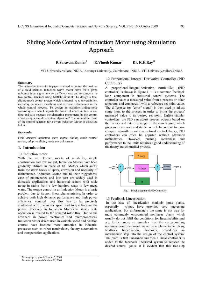
Fig. 15. Simulation Results showing Error and Sliding Surface
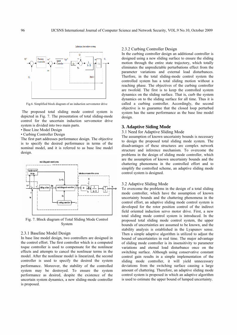
4.1.5 Simulation of Adaptive Sliding Mode Controller
Fig.16 Adaptive Sliding Mode Control Design in SIMULINK
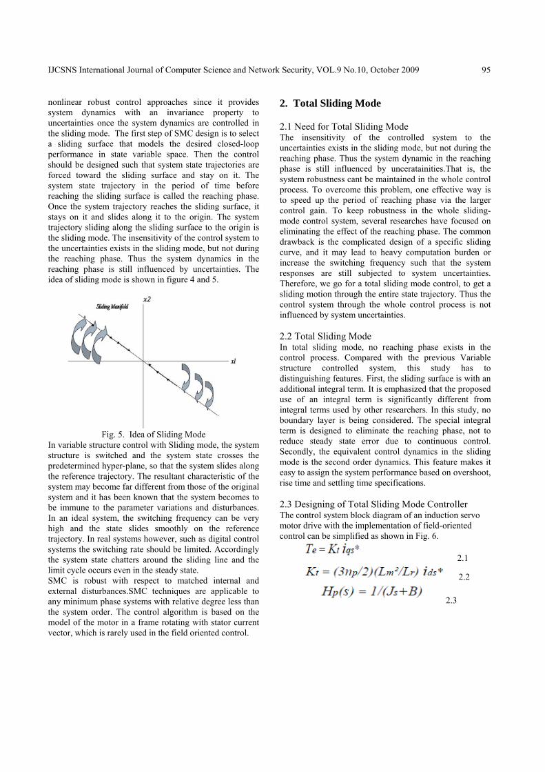
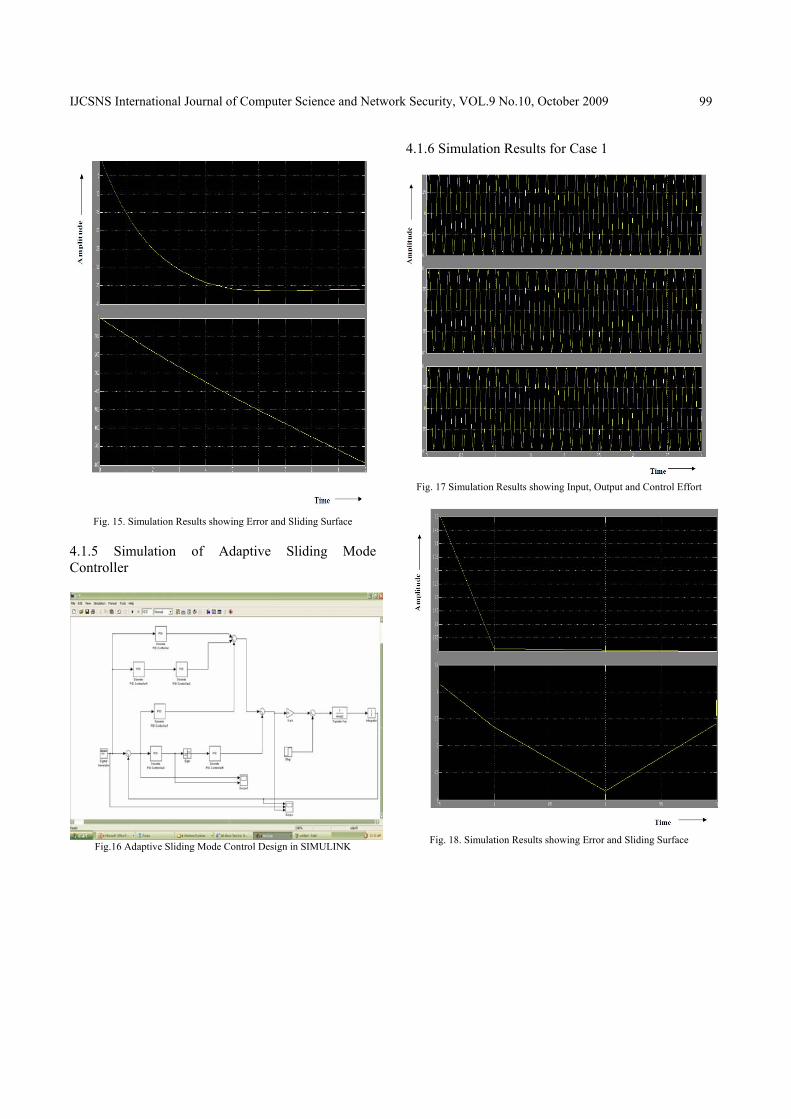
4.1.6 Simulation Results for Case 1
Fig. 17 Simulation Results showing Input, Output and Control Effort
Fig. 18. Simulation Results showing Error and Sliding Surface
IJCSNS International Journal of Computer Science and Network Security, VOL.9 No.10, October 2009
100
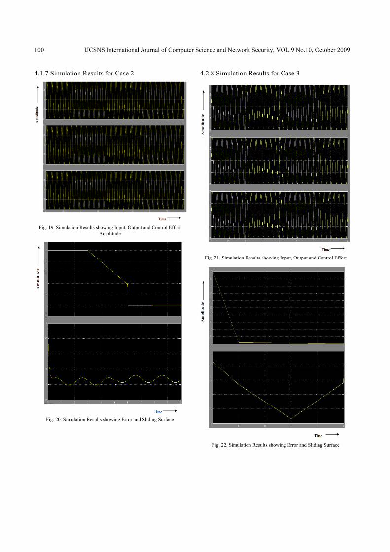
4.1.7 Simulation Results for Case 2
Fig. 19. Simulation Results showing Input, Output and Control Effort
Amplitude
Fig. 20. Simulation Results showing Error and Sliding Surface
4.2.8 Simulation Results for Case 3
Fig. 21. Simulation Results showing Input, Output and Control Effort
Fig. 22. Simulation Results showing Error and Sliding Surface

IJCSNS International Journal of Computer Science and Network Security, VOL.9 No.10, October 2009
101
4.2 Simulation using LABVIEW 4.2.1 Simulation of Total Sliding Mode Controller
Fig 23. Total Sliding Mode Control Design in LABVIEW
4.2.2 Simulation Results for Case 1
Fig.24. Simulation Results showing Input, Output, Control effort, Error
and Sliding surface
4.3.3 Simulation Results for Case 2
Fig.25. Simulation Results showing Input, Output, Control effort, Error
and Sliding surface
4.3.4 Simulation Results for Case 3
Fig.26. Simulation Results showing Input, Output, Control effort, Error
and Sliding surface
IJCSNS International Journal of Computer Science and Network Security, VOL.9 No.10, October 2009
102
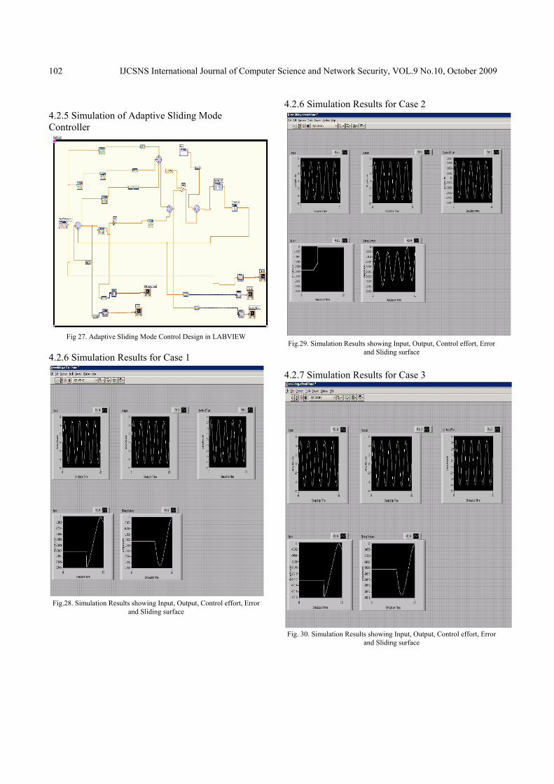
4.2.5 Simulation of Adaptive Sliding Mode Controller
Fig 27. Adaptive Sliding Mode Control Design in LABVIEW
4.2.6 Simulation Results for Case 1
Fig.28. Simulation Results showing Input, Output, Control effort, Error
and Sliding surface
4.2.6 Simulation Results for Case 2
Fig.29. Simulation Results showing Input, Output, Control effort, Error
and Sliding surface
4.2.7 Simulation Results for Case 3
Fig. 30. Simulation Results showing Input, Output, Control effort, Error
and Sliding surface
IJCSNS International Journal of Computer Science and Network Security, VOL.9 No.10, October 2009
103
4.3 Comparison between the two Control Schemes In the simulation, first the proposed total sliding mode control system shown in the Figs. 16 and 27 is considered. The responses of the rotor positions, the controlled effort, the error and the sliding surface trajectory due to the periodic sinusoidal command for case1, case2 and case3 are depicted in Figs.17-22 and 22-30. From the simulated results, perfect tracking responses and robust characteristics are obtained. Moreover, the total sliding motions shown in Figs.15, 18 and 22 confirm the absence of the reaching phase in the total sliding mode control system. The proposed adaptive sliding mode control system shown in Figs. 10 and 12 is now applied to control the system for comparison with the total sliding mode control system. The responses of the rotor position, the control effort, the error and the sliding surface trajectory due to the periodic sinusoidal command for case1, case2 and case3 are depicted in Figs. 23-28 and 29-30. From the simulated results, perfect tracking responses and robust characteristics are obtained for the adaptive sliding mode control system. In addition, the control efforts of the adaptive sliding-mode control system are smaller than that of the total sliding-mode control system. Two conditions of rotor inertia are tested here: One is the nominal inertia and the other is the increasing of rotor inertia to approximately three times the nominal value. Moreover, the simulation results with a 3Nm step-load disturbance occurring at five seconds are depicted in Figs 17, 18 and 29, 30. From simulation results • The tracing errors converge quickly and the robust control characteristics of the adaptive sliding mode control system under the occurance of uncertainities are clearly observed. • The control effort of the adaptive sliding mode control system is smaller than that of the total sliding-mode control system. • The error tries to become zero in the adaptive sliding-mode control system whereas it is constant in total sliding mode control system. • The sliding surface trajectory tries to reach the equilibrium position in the adaptive sliding mode control system whereas it linearly shifts from the equilibrium position in the total sliding mode control system. 5.5 Results A total Sliding mode control system which is insensitive to uncertainties including parameter variations and external disturbances in the whole control process was designed. An adaptive sliding mode control system which adjusts the bound of uncertainties in real time in the control effort using a simple adaptive algorithm was
designed. Both the control schemes for a given induction motor were simulated using MATLAB and LABVIEW. 5. Conclusion The position of a field oriented induction servomotor drive for a given reference input signal was controlled using the total Sliding-Mode Control Schemes and Adaptive Sliding Mode Control Scheme and by comparing the two, it is concluded that the adaptive sliding mode control scheme is more robust and efficient. References [1] Astrom, K.J., and Wittenmark, B., ‘Adaptive control”
(Addison-Wesley, New York, 1995). [2] Benchaib .A, A. Raichid and E. Audrezet, ‘Sliding mode
input-output linearization and field orientation for real-time control of induction motors’ IEEE transactions on power Electronics, vol 14, issue 1, January 1999.
[3] Chern, T.L., and Wu, Y.C., ‘An optimal variable structure control with integral compensation for electro-hydraulic servo control system’. IEEE.Trans.IE39, pp.460-463, 1992.
[4] Imura, J., Sugie, T., and Yoshikawa, T., ‘Adaptive control of robot manipulators – theory and experiment’, IEEE. Trans., RA – IO, pp.705-710, 1994.
[5] T. G. Par and K. S. Lee., ‘SMC-based adaptive input-output linear control of induction motors’ IEE Proc. Contr. Theory Applica., vol.145, no. 1, pp. 55-62, 1998
[6] V. I. Utkin, ‘Sliding mode control design principle and application to electric drives’, IEEE Trans.on Ind. Electron., vol.40, no.1, pp.23-36,1993.
[7] Subhasis Nandi, Hamid A. Toliyat, "Novel Frequency Domain Based Technique to Detect Incipient Stator Inter-Turn Faults in Induction Machines" proceedings of industry application conference, Page(s): 367-374 vol.1 2000,
[8] Weibing Gao., and James C. Hung., ‘Variable Structure Control of Non linear Systems: A New Approach’. IEEE. Trans. IMO, pp.2-22, 1993.
[9] Bimal.K.Bose .,”Modern Power Electronics and AC Drives” ,Pearson Education Ltd. New Delhi., 2003
[10] R.-J.WAI .,”Sliding-mode control for induction servomotor drive” .
[11] Martin Ansbjerg KJÆR .,“Sliding Mode Control “
R.Saravanakumar received his B.E. Degree in Electrical and Electronics Engineering from Thiyagarajar College of Engineering , Madurai, Tamilnadu India in 1996.He obtained M.E., in Power Electronics and Drives from College of Engineering Guindy ,Tamilnadu ,India in 1998.Since 1999,He is with the Vellore
Institute of Technology (VIT)University Tamilnadu ,India working in the School of Electrical Science. Presently he is working as a research scholar for PhD degree in the School of Electrical Science at the VIT University. His present research interests are Condition Monitoring of Industrial Drives, Modeling and simulation of Electrical system, Special machines, Application of Soft computing Technique.
IJCSNS International Journal of Computer Science and Network Security, VOL.9 No.10, October 2009
104
K.Vinoth Kumar is a member of IEEE. He is received his B.E. Degree in Electrical and Electronics Engineering from Anna University , Chennai, Tamilnadu India in 2006.He obtained M.Tech., in Power Electronics and Drives from VIT University, Vellore ,Tamilnadu ,India in 2008. Now he is with the Karunya University Coimbatore, India working in the School
of Electrical science. His present research interests are Condition Monitoring of Industrial Drives, Modeling and simulation of Electrical system, Special machines, Neural Networks and fuzzy logic.
K.K.Ray received his B.E. Degree in Electrical Engineering from Jabalpur University, Calcutta India in 1967.He obtained M.Tech from Indian Institute of Technology Kanpur, Kanpur ,India ,in 1977. From 1967 to 2002, Dr Ray was with the Indian School of Mines University, Dhanbad (Jharkhand), India working in the Department of Engineering and Mining . He received his
PhD degree from the Indian Institute of Technology Delhi, New Delhi,India in 1991. Since 2003 he is with the School of Electrical sciences, VIT University Tamilnadu, India. His present research interests are Power Electronics and Drives, Instrumentation and machines, Reactive Power Compensation, Switchgear Protection.